JP5257609B2 - Optical module and lighting fixture - Google Patents
Optical module and lighting fixture Download PDFInfo
- Publication number
- JP5257609B2 JP5257609B2 JP2009050874A JP2009050874A JP5257609B2 JP 5257609 B2 JP5257609 B2 JP 5257609B2 JP 2009050874 A JP2009050874 A JP 2009050874A JP 2009050874 A JP2009050874 A JP 2009050874A JP 5257609 B2 JP5257609 B2 JP 5257609B2
- Authority
- JP
- Japan
- Prior art keywords
- light
- light source
- lens
- optical module
- led light
- Prior art date
- Legal status (The legal status is an assumption and is not a legal conclusion. Google has not performed a legal analysis and makes no representation as to the accuracy of the status listed.)
- Expired - Fee Related
Links
- 230000003287 optical effect Effects 0.000 title claims description 96
- 238000005286 illumination Methods 0.000 claims description 24
- 239000000758 substrate Substances 0.000 claims description 11
- 230000001154 acute effect Effects 0.000 claims description 4
- 230000001678 irradiating effect Effects 0.000 claims description 3
- 230000000052 comparative effect Effects 0.000 description 4
- 229910001507 metal halide Inorganic materials 0.000 description 4
- 150000005309 metal halides Chemical class 0.000 description 4
- 230000004313 glare Effects 0.000 description 3
- 239000000463 material Substances 0.000 description 3
- 230000005855 radiation Effects 0.000 description 3
- NIXOWILDQLNWCW-UHFFFAOYSA-N acrylic acid group Chemical group C(C=C)(=O)O NIXOWILDQLNWCW-UHFFFAOYSA-N 0.000 description 2
- 230000015572 biosynthetic process Effects 0.000 description 2
- 238000009434 installation Methods 0.000 description 2
- 239000011347 resin Substances 0.000 description 2
- 229920005989 resin Polymers 0.000 description 2
- DGAQECJNVWCQMB-PUAWFVPOSA-M Ilexoside XXIX Chemical compound C[C@@H]1CC[C@@]2(CC[C@@]3(C(=CC[C@H]4[C@]3(CC[C@@H]5[C@@]4(CC[C@@H](C5(C)C)OS(=O)(=O)[O-])C)C)[C@@H]2[C@]1(C)O)C)C(=O)O[C@H]6[C@@H]([C@H]([C@@H]([C@H](O6)CO)O)O)O.[Na+] DGAQECJNVWCQMB-PUAWFVPOSA-M 0.000 description 1
- XUIMIQQOPSSXEZ-UHFFFAOYSA-N Silicon Chemical compound [Si] XUIMIQQOPSSXEZ-UHFFFAOYSA-N 0.000 description 1
- 230000001771 impaired effect Effects 0.000 description 1
- 238000012423 maintenance Methods 0.000 description 1
- 229910052710 silicon Inorganic materials 0.000 description 1
- 239000010703 silicon Substances 0.000 description 1
- 229910052708 sodium Inorganic materials 0.000 description 1
- 239000011734 sodium Substances 0.000 description 1
- 230000005469 synchrotron radiation Effects 0.000 description 1
Images


Classifications
-
- Y—GENERAL TAGGING OF NEW TECHNOLOGICAL DEVELOPMENTS; GENERAL TAGGING OF CROSS-SECTIONAL TECHNOLOGIES SPANNING OVER SEVERAL SECTIONS OF THE IPC; TECHNICAL SUBJECTS COVERED BY FORMER USPC CROSS-REFERENCE ART COLLECTIONS [XRACs] AND DIGESTS
- Y02—TECHNOLOGIES OR APPLICATIONS FOR MITIGATION OR ADAPTATION AGAINST CLIMATE CHANGE
- Y02B—CLIMATE CHANGE MITIGATION TECHNOLOGIES RELATED TO BUILDINGS, e.g. HOUSING, HOUSE APPLIANCES OR RELATED END-USER APPLICATIONS
- Y02B20/00—Energy efficient lighting technologies, e.g. halogen lamps or gas discharge lamps
- Y02B20/72—Energy efficient lighting technologies, e.g. halogen lamps or gas discharge lamps in street lighting
Landscapes
- Non-Portable Lighting Devices Or Systems Thereof (AREA)
Description
本発明は光学モジュール及び照明用灯具に係り、特に道路照明灯具、街路灯具、歩行者灯具、駐車場灯具、埋め込み灯具、又は看板照明灯具等の照射範囲が設定された照明用灯具に使用される光学モジュール及びその照明用灯具に関する。 The present invention relates to an optical module and an illumination lamp, and is particularly used for an illumination lamp in which an irradiation range is set, such as a road illumination lamp, a street lamp, a pedestrian lamp, a parking lot lamp, an embedded lamp, or a signboard lamp. The present invention relates to an optical module and an illumination lamp.
道路や公園などの屋外には、灯具高さの高い照明用灯具が設置されている。この照明用灯具は、広い範囲を照明することが要求されていることから、照明用の光源としてメタルハライドランプや蛍光ランプなどの光出力の高い光源が一般的に使用されている。 Lighting lamps with a high lamp height are installed outside roads and parks. Since this illumination lamp is required to illuminate a wide range, a light source with high light output such as a metal halide lamp or a fluorescent lamp is generally used as a light source for illumination.
しかしながら、メタルハライドランプや蛍光ランプは消費電力が大きく、また、電球交換などの維持費が嵩むという欠点があるため、最近ではこの欠点を解消できる光源としてLED(Light Emitting Diode)光源を使用した照明用灯具が提案されている。 However, metal halide lamps and fluorescent lamps have the disadvantages of high power consumption and high maintenance costs such as bulb replacement. Recently, LED (Light Emitting Diode) light sources can be used for lighting. A light fixture has been proposed.
特許文献1には、LED光源を使用した道路照明灯具が開示されている。 Patent Document 1 discloses a road illumination lamp using an LED light source.
この道路照明灯具は、面発光するLED光源及び集光レンズからなる光学モジュールと、複数の光学モジュールを取り付けるための基板と、この基板を支持するための支持部材とを備えており、基板に取り付けられた複数の光学モジュールからの光が複数の異なる向きに指向せしめられるように、基板を複数段階に屈曲させて構成されている。 This road illumination lamp includes an optical module including a surface emitting LED light source and a condenser lens, a substrate for mounting a plurality of optical modules, and a support member for supporting the substrate, and is attached to the substrate. The substrate is bent in a plurality of stages so that light from the plurality of optical modules is directed in a plurality of different directions.
特許文献1に開示された道路照明灯具の配光に関する考え方は、所望の配光パターンを複数の区画に分割し、各区画を1個の光学モジュールが照射するように、複数の光学モジュールを基板に角度を変えて取り付けたことにある。 The concept regarding the light distribution of the road illumination lamp disclosed in Patent Document 1 is that a desired light distribution pattern is divided into a plurality of sections, and a plurality of optical modules are mounted on the substrate so that each section is irradiated with one optical module. This is because it was installed at a different angle.
また、図11に示すように道路照明灯具100の照射性能は、灯体設置高さをhとした時、灯体間隔pを3hから3.5hをカバーするような拡がりをもつ照射が必要になり、その配光パターンはセミカットオフ形配光パターンが最適と言われている。この道路照明灯具100は、灯体設置高さh=10m、灯体間隔p=35mである。
Moreover, as shown in FIG. 11, the irradiation performance of the
なお、JIS Z9111「道路照度基準」の規格におけるセミカットオフ形配光パターンとは、ランプの光束1000ルーメン当たりの光度が、水平角90°の場合においては、鉛直角80°のときに120カンデラ以下であって、鉛直角90°のときに30カンデラ以下であり、鉛直角65°の場合においては、水平角が65°から95°の範囲で190カンデラ以上(ただし低圧ナトリウム灯器具および蛍光灯器具の場合は170カンデラ以上)の値が存在する配光パターンをいう。 The semi-cut-off light distribution pattern in the standard of JIS Z9111 “Road Illuminance Standard” means that when the luminous intensity per 1000 lumens of the lamp has a horizontal angle of 90 °, the vertical angle is 80 °, and 120 candela. When the vertical angle is 90 °, it is 30 candela or less. When the vertical angle is 65 °, the horizontal angle ranges from 65 ° to 95 ° and is over 190 candela (however, a low-pressure sodium lamp and a fluorescent lamp) In the case of an appliance, it means a light distribution pattern having a value of 170 candela or more.
一方、特許文献2には、LEDを光源として使用し、LED光源から放射される光を、LED光源に近接配置されたレンズによって、LED光源の中心軸に対し直交方向に反射、屈折させて照射する光学モジュールが開示されている。この光学モジュールは、セミカットオフ形配光パターンを得るための光学指向性は有しておらず、道路照明灯具としては不向きである。 On the other hand, in Patent Document 2, an LED is used as a light source, and light emitted from the LED light source is reflected and refracted in a direction orthogonal to the central axis of the LED light source by a lens disposed close to the LED light source. An optical module is disclosed. This optical module does not have optical directivity for obtaining a semi-cut-off light distribution pattern, and is not suitable as a road illumination lamp.
前述したように、夜間において道路や歩道を照射する照明用灯具の光源はメタルハライドランプや蛍光ランプが広く用いられ、いずれも大光量光源である。これに対してLED灯具の光源光量は未だ小光量のため、現状のメタルハライド光源灯具が持つ明るい照明性能と同等にするには、面発光するLED光源とレンズとからなる光学モジュールを多数個集合させることにより光量加算する必要がある。 As described above, metal halide lamps and fluorescent lamps are widely used as light sources for illumination lamps that illuminate roads and sidewalks at night, and both are large light sources. On the other hand, since the light quantity of the light source of the LED lamp is still small, in order to make it equivalent to the bright illumination performance of the current metal halide light source lamp, a large number of optical modules composed of LED light sources and lenses that emit surface light are assembled. Therefore, it is necessary to add the amount of light.
そこで、前記光学モジュールのサイズを光学性能優先で設計すると、個々の光学モジュールを並設した際に灯具サイズが大型化してしまうため、光学モジュールのサイズと光学性能のバランスを考慮したコンパクトな光学設計が必要となる。 Therefore, if the size of the optical module is designed with priority on optical performance, the lamp size will increase when the individual optical modules are installed side by side, so a compact optical design that takes into account the balance between the optical module size and the optical performance Is required.
このため、レンズの焦点距離を短焦点としてコンパクトな外形としているが、この構造ではLED光源の発光面のサイズに対し、焦点距離が短いレンズの組み合わせとなるので、相対的にLED光源の発光面のサイズがレンズよりも大きくなる傾向にある。全反射光学を活用したレンズを想定して設計する場合、基本光学設計はLED光源の原点から放射された光が、所望照射角度方向に屈折するレンズ設計となるが、原点から離れたLED光源からの放射光は、放射角度が次第に大きくなるに従って所望照射角度からずれてくる。更に、LED光源の両端部付近からの放射光は、放射角度が更に大きくなるため制御不能になり、所望照射角度から大きく外れるばかりでなく、有効利用できない雑光も発生し、これがグレアなどの漏れ光となって品質が低下する。これらの問題は、LED光源の発光面サイズよりもレンズサイズを大きくできれば解決できるが、光学モジュールの小型化の要求からレンズサイズを大型化することは好ましくない。 For this reason, the lens has a short focal length and a compact outer shape, but this structure is a combination of lenses with a short focal length relative to the size of the light emitting surface of the LED light source. Tends to be larger than the lens. When designing with the assumption of a lens utilizing total reflection optics, the basic optical design is a lens design in which the light emitted from the origin of the LED light source is refracted in the desired irradiation angle direction, but from the LED light source far from the origin The emitted light deviates from the desired irradiation angle as the radiation angle gradually increases. Furthermore, the emitted light from the vicinity of both ends of the LED light source becomes uncontrollable because the radiation angle is further increased, and not only greatly deviates from the desired irradiation angle, but also miscellaneous light that cannot be used effectively is generated. It becomes light and the quality deteriorates. These problems can be solved if the lens size can be made larger than the light emitting surface size of the LED light source, but it is not preferable to increase the lens size because of the demand for downsizing the optical module.
一方で特許文献1の照明用灯具は、技術開発によりLED光源の光量が増大し、光学モジュールの個数を削減しようとした場合、各々の光学モジュールは、セミカットオフ形配光パターンのなかの指定された区画を照明しているため、削減した光学モジュールが担う区画が暗くなり、セミカットオフ形配光パターンに欠落現象が生じるという問題がある。このような問題は、各々の光学モジュールにセミカットオフ形配光パターンを得るための光学指向性を持たせれば解消できる。 On the other hand, in the illumination lamp of Patent Document 1, when the light quantity of the LED light source increases due to technological development and the number of optical modules is to be reduced, each optical module is designated in a semi-cut-off light distribution pattern. Since the divided sections are illuminated, the sections of the reduced optical module are darkened, and there is a problem in that a missing phenomenon occurs in the semi-cut-off light distribution pattern. Such a problem can be solved if each optical module has optical directivity for obtaining a semi-cut-off light distribution pattern.
しかしながら、LED光源の発光面のサイズがレンズに対して大きい光学モジュールの場合、凸レンズでは屈折角に限界があるため、広角に照射できずセミカットオフ形配光パターンの全範囲を照射することができない。 However, in the case of an optical module in which the size of the light emitting surface of the LED light source is larger than that of the lens, the refractive angle of the convex lens is limited, so that it is not possible to irradiate a wide angle and the entire range of the semi-cutoff light distribution pattern can be irradiated. Can not.
本発明は、このような事情に鑑みてなされたもので、面発光するLED光源を使用した光学モジュールであって、LED光源の発光面サイズがレンズに対して大きい光学モジュールにおいて、グレアなどの漏れ光に起因するLED光源の両端部から放射される光を有効利用して、所望の配光パターンを得ることができる光学モジュール及び照明用灯具を提供することを目的とする。 The present invention has been made in view of such circumstances, and is an optical module using an LED light source that emits surface light, and in an optical module in which the light emitting surface size of the LED light source is larger than that of a lens, leakage of glare and the like. An object of the present invention is to provide an optical module and an illumination lamp capable of obtaining a desired light distribution pattern by effectively using light emitted from both ends of an LED light source caused by light.
本発明は、前記目的を達成するために、レンズ及び該レンズの焦点位置にその原点が略配置された面発光するLED光源を有し、前記LED光源の発光面端部と光軸と入射面の交点との角度が大きく、前記LED光源の発光面サイズに対してレンズ焦点距離が略同等か、若しくは、前記発光面サイズの方がレンズ焦点距離よりも長い光学モジュールにおいて、前記レンズの表面には、前記LED光源の前記原点を通る中心軸の両側の所定の領域に反射部が形成されるとともに、該反射部の両側の領域に凸レンズ部が形成され、前記凸レンズ部は、前記LED光源の原点から放射された光を屈折で、前記両反射部の中央線と直角な方向に第1の角度範囲を持つ拡散光を照射し、前記反射部は、前記LED光源の原点から放射された光を全反射と屈折で、前記両反射部の中央線と直角な方向に第2の角度範囲を持つ拡散光を照射し、更に前記反射部は、前記LED光源の端部から放射される鋭角で、かつ、高輝度な光を全反射と屈折で、前記両反射部の中央線と直角な方向に前記第1の角度範囲及び第2の角度範囲よりも広角な第3の角度範囲を持つ拡散光を照射し、所望のセミカットオフ形配光パターンを形成することを特徴とする光学モジュールを提供する。 In order to achieve the above object, the present invention has a lens and a surface-emitting LED light source whose origin is substantially arranged at the focal position of the lens, and the light emitting surface end, the optical axis, and the incident surface of the LED light source. In the optical module, the lens focal length is substantially equal to the light emitting surface size of the LED light source, or the light emitting surface size is longer than the lens focal length. Is formed with a reflective portion in a predetermined region on both sides of the central axis passing through the origin of the LED light source, and a convex lens portion is formed on a region on both sides of the reflective portion. The light emitted from the origin is refracted, and the diffused light having the first angle range is irradiated in a direction perpendicular to the center line of the two reflecting parts, and the reflecting part is the light emitted from the origin of the LED light source. The total reflection and The diffused light having a second angle range is irradiated in a direction perpendicular to the center line of the two reflection portions, and the reflection portion has an acute angle radiated from an end portion of the LED light source and a high height. Bright light is totally reflected and refracted and irradiated with diffused light having a third angle range wider than the first angle range and the second angle range in a direction perpendicular to the center line of the two reflecting portions. An optical module is provided that forms a desired semi-cut-off light distribution pattern.
本発明によれば、レンズの凸レンズ部によって、LED光源の原点から放射された光を屈折で、両反射部の中央線と直角な方向に第1の角度範囲を持つ拡散光を照射する。そして、反射部は、LED光源の原点から放射された光を全反射と屈折で、両反射部の中央線と直角な方向に第2の角度範囲を持つ拡散光を照射し、更に反射部は、LED光源の端部から放射される鋭角で、かつ、高輝度な光を全反射と屈折で、両反射部の中央線と直角な方向に前記第1の角度範囲及び第2の角度範囲よりも広角な第3の角度範囲を持つ拡散光を照射する。これによって、所望のセミカットオフ形配光パターンを形成することができる。これにより、LED光源の両端部から放射された光は、制御不能な雑光とならず、所望の配光パターンの形成に寄与する。よって、本発明の光学モジュールによれば、面発光するLED光源を使用した光学モジュールであって、LED光源の発光面サイズがレンズに対して大きい光学モジュールにおいて、グレアなどの漏れ光に起因するLED光源の両端部から放射される光を有効利用して、所望の配光パターンを得ることができる。 According to the present invention, the light radiated from the origin of the LED light source is refracted by the convex lens portion of the lens, and the diffused light having the first angle range is irradiated in a direction perpendicular to the center line of both reflection portions. The reflection unit irradiates light emitted from the origin of the LED light source with total reflection and refraction, and diffusing light having a second angle range in a direction perpendicular to the center line of both reflection units. From the first angle range and the second angle range in a direction perpendicular to the center line of both reflection portions by the total reflection and refraction of the acute angle and high-intensity light emitted from the end of the LED light source Also irradiates diffuse light having a wide third angle range. As a result, a desired semi-cutoff light distribution pattern can be formed. Thereby, the light radiated | emitted from the both ends of the LED light source does not become uncontrollable miscellaneous light, but contributes to formation of a desired light distribution pattern. Therefore, according to the optical module of the present invention, an optical module that uses an LED light source that emits surface light, and the light source surface size of the LED light source is larger than that of the lens. A desired light distribution pattern can be obtained by effectively using light emitted from both ends of the light source.
また、本発明の前記反射部は、前記反射部は、前記中心軸に対して左右両側に形成されるとともに断面三角形状に形成されていることが好ましい。 Moreover, it is preferable that the said reflection part of this invention is formed in the cross-sectional triangle shape while the said reflection part is formed in both right-and-left both sides with respect to the said central axis.
更に、本発明によれば、前記第1の角度範囲は片側約65°以内であり、前記第2の角度範囲は片側約45°〜65°であり、前記第3の角度範囲は片側約65°〜74°の範囲であることが好ましい。 Further in accordance with the present invention, the first angular range is within about 65 ° on one side, the second angular range is about 45 ° to 65 ° on one side, and the third angular range is about 65 on one side. It is preferable that it is in the range of ° to 74 °.
現行規格のセミカットオフ形配光パターンを形成する際、凸レンズ部では片側約0°から片側約65°の範囲(第1の角度範囲)まで有効光を出射することができ、片側約65°から片側74°の範囲に有効光を出射することができないが、反射部によって、片側約65°から片側74°の範囲(第3の角度範囲)に有効光を出射することができる。よって、本発明によれば、LED光源の両端部から放射される光を有効利用して、現行規格のセミカットオフ形配光パターンを得ることができる。 When forming a semi-cut-off light distribution pattern of the current standard, the convex lens portion can emit effective light from about 0 ° on one side to about 65 ° on one side (first angle range), and about 65 ° on one side. Effective light cannot be emitted in a range of 74 ° from one side to 74 ° on one side, but effective light can be emitted from a range of about 65 ° on one side to 74 ° on one side (third angle range) by the reflecting portion. Therefore, according to the present invention, the light emitted from both ends of the LED light source can be effectively used to obtain a semi-cut-off light distribution pattern of the current standard.
また、本発明の光学モジュールが基板に複数個配設され、光学モジュールは少なくとも1組の灯体に組み付けられ、照射対象面に対して平行若しくは上方斜めに傾斜して取り付けられることを特徴とする照明用灯具を提供する。 In addition, a plurality of optical modules of the present invention are disposed on a substrate, the optical modules are assembled to at least one set of lamps, and are mounted parallel to the irradiation target surface or inclined obliquely upward. Provide lighting fixtures.
本発明の光学モジュールは、所望の配光パターンを得ることができる光学指向性を有しているため、特許文献1の如く光学モジュールの中心軸を区画に向ける必要はなく、道路などの照射対象面に対して直交方向に向けて配置すればよい。すなわち、本発明の照明用灯具によれば、複数個配設された光学モジュールの基板を、照射対象面に対して平行若しくは上方斜めに傾斜して取り付けるだけで照明用灯具を構成することができる。 Since the optical module of the present invention has optical directivity capable of obtaining a desired light distribution pattern, it is not necessary to direct the central axis of the optical module to a section as in Patent Document 1, and an irradiation target such as a road What is necessary is just to arrange | position toward the orthogonal direction with respect to a surface. That is, according to the lighting lamp of the present invention, the lighting lamp can be configured by simply mounting a plurality of optical module substrates arranged parallel or obliquely upward with respect to the irradiation target surface. .
また、本発明の光学モジュールは、各々の光学モジュールが所望の配光パターンを得ることができる光学指向性を有しているので、LED光源の光量増加に伴う光学モジュールの個数を削減しても、配光パターンに欠落現象は生じず、良好な配光パターンを得ることができる。 Moreover, since the optical module of the present invention has an optical directivity that allows each optical module to obtain a desired light distribution pattern, the number of optical modules can be reduced as the light quantity of the LED light source increases. In this case, no omission phenomenon occurs in the light distribution pattern, and a good light distribution pattern can be obtained.
一方、レンズの反射部は、LED光源の中心軸に対して左右約30°以上の範囲に形成されていることが好ましい。また、このレンズは、LED光源から放射される全光量を光学制御して、半球状の有効発光領域から出射することができる。更に、LED光源とレンズとの間は空気層でもよく、屈折率が約1.5の樹脂(シリコン樹脂)をLED光源とレンズとの間に充填してもよい。 On the other hand, the reflecting portion of the lens is preferably formed in a range of about 30 ° or more on the left and right with respect to the central axis of the LED light source. In addition, this lens can optically control the total amount of light emitted from the LED light source and emit the light from a hemispherical effective light emitting region. Further, an air layer may be provided between the LED light source and the lens, and a resin (silicon resin) having a refractive index of about 1.5 may be filled between the LED light source and the lens.
以上説明したように本発明の光学モジュール及び照明用灯具によれば、面発光するLED光源を使用した光学モジュールであって、LED光源の発光面サイズに対してレンズ焦点距離が発光面サイズより同等若しくは短い光学モジュールにおいて、グレアなどの漏れ光に起因するLED光源の両端部から放射される光を有効利用して、所望の配光パターンを得ることができる。 As described above, according to the optical module and the illumination lamp of the present invention, the optical module uses a surface-emitting LED light source, and the lens focal length is equal to the light-emitting surface size of the LED light source. Alternatively, in a short optical module, a desired light distribution pattern can be obtained by effectively using light emitted from both ends of the LED light source due to leakage light such as glare.
以下、添付図面に従って本発明に係る光学モジュール及び照明用灯具の好ましい実施の形態について詳説する。 Hereinafter, preferred embodiments of an optical module and an illumination lamp according to the present invention will be described in detail with reference to the accompanying drawings.
図1には、本発明の第1の実施の形態の光学モジュール10であって、道路照明灯具に好適な光学モジュール10の外観図が示されている。図2は光学モジュール10の平面図、図3(A)は、図2に示した光学モジュール10をA−A線で切断した断面図、図3(B)は、図2に示した光学モジュール10をB−B線で切断した断面図である。
FIG. 1 is an external view of an
光学モジュール10は図3(A)、(B)に示すように、レンズ12及びLED光源14から構成される。LED光源14は面発光の光源であり、レンズ12の焦点位置にその原点Pが略配置されている。原点Pとは、LED光源14の中心軸Z上のLED光源14の上面位置である。また、レンズ12の焦点距離とは、原点Pから原点Pの直上にあるレンズ入射面までの距離である。この光学モジュール10は、レンズ12の焦点距離を短焦点としたコンパクトな外形であるが、LED光源14の発光面15のサイズがレンズ12に対して大きい光学モジュールに構成されている。
The
ところで、車両が通行する道路を照らし出す路側帯に設置された道路照明灯具を、LED光源14で灯具構成をした場合、求められる配光パターンは、図11に示したセミカットオフ形配光パターンである。また、路面を均一な明るさで照明するために光学軸直上は指向性を弱め、側方60°方向の指向性を強める必要がある。LED光源14の配光指向特性は図4に示すように、路面に対して垂直な面直上に指向性が高いランバシアン分布である。このランバシアン分布の配光パターンを、図11に示したセミカットオフ形配光パターンに対応した指向性に整えるために、レンズ(材料:アクリル、屈折率n=1.492)12によって配光分布設計により調整している。
By the way, when the road illumination lamp installed in the roadside zone that illuminates the road on which the vehicle passes is configured by the
配光分布設計によりLED光源14の発光面15のサイズに対してレンズ焦点距離が短くなると、必然的に意図しない方向へ照射されてしまう雑光の光量が増加していく。LED光源14の発光面15のサイズは、レンズ焦点距離に対する比率で以下のように表現できる。
When the lens focal length becomes shorter than the size of the
この場合、発光面サイズに対して、レンズ焦点距離が長いので、発光面端部付近からの放射光のレンズへの入射角度は小さいため、レンズからの照射角度は所望角度に近くなり、雑光が発生するようなことはない。しかし、図4のランバシアン分布を見ても分かるように、レンズに入射するLED光源からの放射光の有効角度範囲は狭くなるため、LED光源の光利用率は悪くなり照射される光量は少なくなる。また、焦点距離が長いので光学系も長尺化し、小型化には有効な手段とは言えないことは明らかである。 In this case, since the focal length of the lens is longer than the size of the light emitting surface, the incident angle of the emitted light from the vicinity of the end of the light emitting surface to the lens is small. Will not occur. However, as can be seen from the Lambertian distribution of FIG. 4, the effective angle range of the emitted light from the LED light source incident on the lens is narrowed, so the light utilization rate of the LED light source is deteriorated and the amount of light irradiated is reduced. . In addition, since the focal length is long, the optical system is lengthened, and it is obvious that it is not an effective means for miniaturization.
また、短焦点距離になるに従い見た目の発光面15のサイズが大きく比率が逆転する場合もある。
In addition, as the focal length becomes shorter, the apparent size of the
図12の(A)、(B)、(C)で示した比較例の光学モジュール110では、
発光面サイズ:レンズ焦点距離=4mm:4mm
であり、双方は同一寸法である。
In the
Light emitting surface size: Lens focal length = 4 mm: 4 mm
Both have the same dimensions.
セミカットオフ形配光パターンの形成により、LED光源114の原点Pからの放射光を所望の方向(例えば左右60°方向)へ向うように配光設計をするが、発光面115のサイズに対して短焦点距離のためにLED光源114の両端部からの光は必然的に見た目の光源サイズ角度分±15°を含め拡大された投影像を形成する(60°を狙うと左右15°方向へ向う光もある)。結果、0°方向近傍である灯具真下に照射する光量が多過ぎて分散し難い状況となり、路面照度均一性を損なう。
By forming a semi-cut-off light distribution pattern, the light distribution is designed so that the emitted light from the origin P of the LED
そこで、比較例のレンズ112では、全反射を用いた反射部118、118をレンズ112の表面に形成し、屈折レンズである凸レンズ部116、116と合成したレンズ設計を行う。
Therefore, in the
それでも発光面115のサイズに対する短焦点距離が与える悪影響は大きく、LED光源114の両端部付近から放射された光は、制御された方向(狙った主光軸から±15°以内)に有効出射できず、内部損失や180°以上の方向に向う雑光になる。
Nevertheless, the short focal length has a bad influence on the size of the
LED光源114の両端部からの発光も含め雑光を発生させず、LED光源14の一般指向特性である図4のランバシアン分布の配光パターンから、図11のセミカットオフ形配光パターンに変更するレンズが図1〜図3に示したレンズ12である。
The light distribution pattern including the light emitted from both ends of the LED
比較例の光学モジュール110を踏まえて、図1に示した実施の形態の光学モジュール10では、レンズ12は全体として略半球形状に形成され、その表面には、LED光源14の中心軸Zの両側の所定の領域に反射部18、18が形成されるとともに、これらの反射部18、18の両側の領域に凸レンズ部16が形成されている。凸レンズ部16は、LED光源14の原点Pから放射される左右30°を超える放射光を主に屈折で、両反射部18、18の中央線と直角な方向に第1の角度範囲を持つ拡散光を照射して、図11に示したセミカットオフ形配光パターンの一部を形成する。また、反射部18は、LED光源14の原点Pから放射される左右30°以下の放射光を全反射と屈折で、両反射部18、18の中央線と直角な方向に第2の角度範囲を持つ拡散光を照射するとともに、LED光源14の端部付近から放射される鋭角で、かつ、高輝度な放射光を全反射と屈折で、両反射部18、18の中央線と直角な方向に、前述した第1の角度範囲、及び第2の角度範囲よりも広角な第3の角度範囲を持つ光を照射して、セミカットオフ形配光パターンを形成する。第1〜第3の角度範囲については後述する。
In consideration of the
現行規格のセミカットオフ形配光パターンを形成する際、図5に示すように凸レンズ部16では、LED光源14の原点Pから放射された光を、片側約0°から約65°の範囲(第1の角度範囲)まで有効光を出射することができ、片側約65°から片側74°の範囲に有効光を出射することができない。なお、図5では、原点Pから放射された光の光線が示され、そのなかには片側80°近傍まで出射された光線が示されているが、片側約65°を超えた光線の照度は非常に低く有効光として利用できない。つまり、凸レンズ部16では、セミカットオフ形配光パターンのうち片側約0°から片側約65°までの配光パターンしか得ることができない。
When forming the semi-cut-off light distribution pattern of the current standard, as shown in FIG. 5, the
そこで、一部重複するが片側約45°から片側74°まで範囲(第2の角度範囲、第3の角度範囲)の配光パターンを、反射部18、18によって得るようにしている。
In view of this, the light distribution patterns in the range (second angle range, third angle range) from about 45 ° on one side to 74 ° on one side are obtained by the
すなわち、反射部18は、図6(A)、(B)、(C)に示すように、中心軸Zに対して左右両側に形成されるとともに断面三角形状に形成されている。また、反射部18は図1の如く、略半球形状のレンズ12の表面において円周方向に円弧状に形成されている。以下、図6において左側の反射部18について説明する。
That is, as shown in FIGS. 6A, 6 </ b> B, and 6 </ b> C, the
反射部18の対向する一対の面18A、18Bのうち一方面18Aは、図6(A)で示すように、中心軸Zに対して左方に22°の角度に傾斜して形成され、LED光源14の中央から左右30°に放射された光を中心軸Zに対し、主として左側に約45°の方向に反射する。反射部18の傾斜角度は、原点Pから端部までの発光面15から放射される光が傾斜面に当たった時全反射されるような角度であればよい。このため、レンズ12の材料であるアクリルの全反射角度は42°なので、反射部18の傾斜角度は48°以下であればよいが、原点Pから左右30°の放射光を45°以上の出射光に反射する必要があるため、下限の角度は約20°になる。レンズの材質が変更され、また、発光面サイズとレンズ焦点距離の比率が変更されれば、その傾斜角度範囲が変更されるのは言うまでもない。また、一方面18Aは、図6(B)で示すように、LED光源14の左端から放射された高輝度の光を中心軸Zに対し、主として左側に約74°の方向に反射する。この放射光は中央から30°以内の強い光のため、凸レンズ部16で得られる74°の出射光に比べて、明るい有効光として利用できる。一方、他方面18Bは、中心軸Zに対して平行か、若しくは、若干量右方に所定角度傾斜して形成され、図6(C)で示すように、LED光源14の右端から放射された光を中心軸Zに対し、主として右側に約45°〜65°の方向に反射する。なお、右側の反射部18は、左側の反射部18に対して左右対象方向にLED光源14からの光を反射する。
As shown in FIG. 6 (A), one
この反射部18、18によって反射された光により、図11に示したセミカットオフ形配光パターンの片側約0°〜片側約65°の範囲(第1の角度範囲)の照射光は主にLED光源14の原点Pから放射される左右30°以上の放射光で形成され、片側約45°から片側約65°までの範囲(第2の角度範囲)の照射光はLED光源14の端部付近から放射される左右30°を超える放射光で形成され、片側約65°から片側約74°までの範囲(第3の角度範囲)の照射光はLED光源14の端部付近から放射される左右30°以下の高輝度の放射光で形成される。
The light reflected by the reflecting
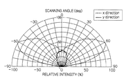
よって、第1の実施の形態の光学モジュール10によれば、LED光源14の両端部から放射される鋭角な左右30°以下の高輝度の光を有効利用して、現行規格のセミカットオフ形配光パターンを得ることができる。なお、図7は、光学モジュール10による配光指向特性が示され、両側60°近傍に光量のピークを有している。
Therefore, according to the
図8は、第2の実施の形態の光学モジュール20の断面図であり、図6に示した第1の実施の形態の光学モジュール10と同一又は類似の部材については同一の符号を付し、その説明は省略する。
FIG. 8 is a cross-sectional view of the
この光学モジュール20は、レンズ22及びLED光源14から構成されている。レンズ22は、凸レンズ部16と反射部28とから構成されている。
The
反射部28は、図8(A)、(B)、(C)に示すように、中心軸Zに対して左右両側に形成されており、片側それぞれ連続した2段の断面三角形状に形成されている。以下、図8において左側の反射部28について説明する。
As shown in FIGS. 8A, 8 </ b> B, and 8 </ b> C, the
この反射部28は、片側2段目(中心軸に対して近いものを片側1断面、遠いものも片側2段目目を規定する)の断面三角形の垂直線と凸レンズ部16の表面が交わる点と原点Pが通る直線と中心軸Zのなす角度は約30°である。また、片側2段目の断面三角形の垂直面と片側1段目の断面三角形の傾斜面を延長して交わる点と、片側2断面の断面三角形の垂直面と凸レンズ16が交わる点と、中心軸Zがレンズ22の表面で交わる点の3点を結んで形成される三角形は、図3(A)で示したレンズ12の片側の断面三角形の反射部18と略同じ形状となる。
This reflecting
反射部28は、図8(A)で示すように、LED光源14の中央から放射された光を中心軸Zに対し、主として左側に約45°の方向に反射する。また、反射部28は、図8(B)で示すように、LED光源14の左端から放射された高輝度の光を中心軸Zに対し、主として左側に約65°から約74°の方向に反射する。そして、反射部28は、図8(C)で示すように、LED光源14の右端から放射された光を中心軸Zに対し、主として右側約45°から約65°までの方向に反射する。なお、右側の反射部28は、左側の反射部28に対して左右対象方向にLED光源14からの光を反射する。
As shown in FIG. 8A, the
この反射部28、28によって反射された光により、図11に示したセミカットオフ形配光パターンの片側約45°の照射光は、主にLED光源14の原点Pから放射される左右30°以下の放射光で形成され、片側約45°から片側約65°までの照射光は、主にLED光源14の端部付近から放射される左右30°を超える放射光で形成され、片側約65°から片側約74°までの照射光は、主にLED光源14の端部付近から放射される左右30°以下の高光度の放射光で形成される。
With the light reflected by the
よって、第2の実施の形態の光学モジュール10によれば、LED光源14の両端部から放射される光を有効利用して、現行規格のセミカットオフ形配光パターンを得ることができる。また、この光学モジュール20によれば、指向特性を中心軸Zより最高指向角度を微細に制御する場合に、光損失が少なく有効に働く。なお、図9は、光学モジュール20による配光指向特性が示され、両側56°近傍に光量のピークを有している。
Therefore, according to the
なお、レンズ22の反射部28において、片側2段目の断面三角形の高さが片側1段目の断面三角形の高さと同じ程度であれば、LED光源14の発光面15の端部からの放射光が片側1段目の断面三角形に反射、屈折して60°〜74°方向に出射した場合、片側2段目の断面三角形の傾斜面で反射されるという問題がある。この問題を解消するため、片側2段目の断面三角形の高さを片側2段目の断面三角形の高さよりも低くして、片側1段目の断面三角形から出射した60°〜74°方向の光を、片側2段目の三角形状で遮ることなく照射することが好ましい。
In addition, in the
図10(A)は、図1に示した光学モジュール10、10…が基板30上に縦横方向に並列配置されて構成された灯具ユニット32が示されている。
FIG. 10A shows a
この灯具ユニット32を図10(B)に示す道路照明灯具34の灯体36のランプ傘38に、基板30が路面に対して平行若しくは傾くように取り付ける。この道路照明灯具34が照明する道路が、図11の如く二車線通行道路であれば、灯具ユニット32の傾斜角度を上向きに約20°傾けた方が効率よく二車線通行道路全体を照らすことができるが、中央分離帯や駐車場などの照射したい場所が中央に位置している場合、灯体36もその場所の中央に設置するため、灯具ユニット32の傾斜角度は路面に平行に取り付けた方がよい。また、道路斜線の数によっては最適な傾斜角度が変わるため、灯具ユニット32の傾斜角度は約0°〜約20°が適正な範囲となる。灯具ユニット32は、各々の光学モジュール10、10…がセミカットオフ形配光パターンを得ることができる光学指向性を有しているので、LED光源14の光量増加に伴う光学モジュール10の個数を削減しても、セミカットオフ形配光パターンに欠落現象は生じず、良好なセミカットオフ形配光パターンを得ることができる。
The
以上述べた実施の形態では、所望の配光パターンをセミカットオフ形配光パターンに例えて説明したが、配光パターンはセミカットオフ形配光パターンに限定されるものではない。 In the embodiments described above, the desired light distribution pattern is described as being a semi-cutoff light distribution pattern, but the light distribution pattern is not limited to the semi-cutoff light distribution pattern.
すなわち、本発明の光学モジュールの特徴は、凸レンズ部16によって、LED光源14の原点Pから放射された光を屈折で、両反射部18、18の中央線と直角な方向に第1の角度範囲(片側約0°から片側約65°)を持つ拡散光を照射する。そして、反射部18、18は、LED光源14の原点Pから放射された光を全反射と屈折で、両反射部18、18の中央線と直角な方向に第2の角度範囲(片側約45°から片側約65°)を持つ拡散光を照射し、更に反射部18、18は、LED光源14の端部から放射される鋭角で、かつ、高輝度な光を全反射と屈折で、両反射部18、18の中央線と直角な方向に前記第1の角度範囲及び第2の角度範囲よりも広角な第3の角度範囲(片側約65°から片側約74°)を持つ拡散光を照射する。これによって、図11に示したセミカットオフ形配光パターンを形成することにある。
That is, the optical module of the present invention is characterized in that the light radiated from the origin P of the
これにより、LED光源14の両端部から放射された光は、制御不能な雑光とならず、所望の配光パターンの形成に寄与する。よって、本発明の光学モジュールによれば、面発光するLED光源を使用した光学モジュールであってLED光源の発光面サイズに対してレンズ焦点距離が発光面サイズより同等若しくは短い光学モジュールにおいて、グレアなどの漏れ光に起因するLED光源の両端部から放射される光を有効利用して、所望の配光パターンを得ることができる。
Thereby, the light radiated | emitted from the both ends of the
上述した実施の形態においては、光学モジュール10を道路照明灯具に適用した例を説明したが、街路灯具、歩行者灯具、駐車場灯具、埋め込み灯具、又は看板照明灯具等の照射範囲が設定された照明用灯具に光学モジュール10を適用することができる。
In the above-described embodiment, the example in which the
10…光学モジュール、12…レンズ、14…LED光源、15…発光面、16…凸レンズ部、18…反射部、20…光学モジュール、22…レンズ、28…反射部、30…基板、32…灯具ユニット、34…道路照明灯具、36…灯体、38…ランプ傘
DESCRIPTION OF
Claims (4)
前記レンズの表面には、前記LED光源の前記原点を通る中心軸の両側の所定の領域に反射部が形成されるとともに、該反射部の両側の領域に凸レンズ部が形成され、
前記凸レンズ部は、前記LED光源の原点から放射された光を屈折で、前記両反射部の中央線と直角な方向に第1の角度範囲を持つ拡散光を照射し、
前記反射部は、前記LED光源の原点から放射された光を全反射と屈折で、前記両反射部の中央線と直角な方向に第2の角度範囲を持つ拡散光を照射し、更に前記反射部は、前記LED光源の端部から放射される鋭角で、かつ、高輝度な光を全反射と屈折で、前記両反射部の中央線と直角な方向に前記第1の角度範囲及び第2の角度範囲よりも広角な第3の角度範囲を持つ拡散光を照射し、所望のセミカットオフ形配光パターンを形成することを特徴とする光学モジュール。 A lens and a surface-emitting LED light source whose origin is substantially arranged at the focal position of the lens, and the angle between the light emitting surface end of the LED light source and the intersection of the optical axis and the incident surface is large; In the optical module, the lens focal length is substantially equal to the light emitting surface size, or the light emitting surface size is longer than the lens focal length.
On the surface of the lens, a reflection portion is formed in a predetermined region on both sides of the central axis passing through the origin of the LED light source, and a convex lens portion is formed in a region on both sides of the reflection portion,
The convex lens unit refracts light emitted from the origin of the LED light source, and irradiates diffused light having a first angle range in a direction perpendicular to the center line of the two reflecting units,
The reflection unit irradiates light emitted from the origin of the LED light source with total reflection and refraction, irradiates diffuse light having a second angle range in a direction perpendicular to the center line of the both reflection units, and further reflects the reflection The acute angle radiated from the end of the LED light source and the high-brightness light are totally reflected and refracted, and the first angle range and the second angle in a direction perpendicular to the center line of the two reflective portions. An optical module characterized by irradiating diffused light having a third angle range wider than the angle range to form a desired semi-cut-off light distribution pattern.
Priority Applications (1)
| Application Number | Priority Date | Filing Date | Title |
|---|---|---|---|
| JP2009050874A JP5257609B2 (en) | 2009-03-04 | 2009-03-04 | Optical module and lighting fixture |
Applications Claiming Priority (1)
| Application Number | Priority Date | Filing Date | Title |
|---|---|---|---|
| JP2009050874A JP5257609B2 (en) | 2009-03-04 | 2009-03-04 | Optical module and lighting fixture |
Publications (2)
| Publication Number | Publication Date |
|---|---|
| JP2010205605A JP2010205605A (en) | 2010-09-16 |
| JP5257609B2 true JP5257609B2 (en) | 2013-08-07 |
Family
ID=42966891
Family Applications (1)
| Application Number | Title | Priority Date | Filing Date |
|---|---|---|---|
| JP2009050874A Expired - Fee Related JP5257609B2 (en) | 2009-03-04 | 2009-03-04 | Optical module and lighting fixture |
Country Status (1)
| Country | Link |
|---|---|
| JP (1) | JP5257609B2 (en) |
Families Citing this family (12)
| Publication number | Priority date | Publication date | Assignee | Title |
|---|---|---|---|---|
| JP5580707B2 (en) * | 2010-09-29 | 2014-08-27 | 日立マクセル株式会社 | Lighting device |
| WO2012042833A1 (en) * | 2010-09-29 | 2012-04-05 | マクセルファインテック株式会社 | Light source device, light source lens, and lighting device |
| JP4746152B1 (en) * | 2010-12-17 | 2011-08-10 | 光電気通信システム株式会社 | Illumination device for display |
| KR101177760B1 (en) | 2011-05-31 | 2012-08-30 | 한국광기술원 | Illumination device for street light |
| JP6028412B2 (en) * | 2012-06-25 | 2016-11-16 | 岩崎電気株式会社 | Light source unit and lighting apparatus |
| JP6119166B2 (en) * | 2012-09-28 | 2017-04-26 | 岩崎電気株式会社 | Light emitting element unit and lighting apparatus |
| JP6454938B2 (en) * | 2014-10-24 | 2019-01-23 | パナソニックIpマネジメント株式会社 | lighting equipment |
| JP6655807B2 (en) * | 2015-03-04 | 2020-02-26 | パナソニックIpマネジメント株式会社 | Lens unit and lighting equipment |
| KR101643290B1 (en) * | 2015-05-13 | 2016-07-28 | (주)링크옵틱스 | LED lamp for preventing ligt pollution |
| CN106594580B (en) * | 2016-10-21 | 2019-08-13 | 众普森科技(株洲)有限公司 | A kind of LED street lamp combining light distribution, high heat dissipation |
| JP2017162836A (en) * | 2017-05-15 | 2017-09-14 | 東芝ライテック株式会社 | lighting equipment |
| JP7280126B2 (en) * | 2019-06-28 | 2023-05-23 | コイト電工株式会社 | optical lens |
Family Cites Families (8)
| Publication number | Priority date | Publication date | Assignee | Title |
|---|---|---|---|---|
| JPH10275507A (en) * | 1997-03-31 | 1998-10-13 | Matsushita Electric Works Ltd | Road lamp |
| US6679621B2 (en) * | 2002-06-24 | 2004-01-20 | Lumileds Lighting U.S., Llc | Side emitting LED and lens |
| JP4182784B2 (en) * | 2003-03-14 | 2008-11-19 | 豊田合成株式会社 | Light emitting device and manufacturing method thereof |
| KR100688767B1 (en) * | 2004-10-15 | 2007-02-28 | 삼성전기주식회사 | Lens for LED Light Source |
| KR100661261B1 (en) * | 2005-05-23 | 2006-12-26 | 주식회사 세코닉스 | LED diffused lens |
| JP2007173322A (en) * | 2005-12-19 | 2007-07-05 | Enplas Corp | Light emitting device |
| JP2008258007A (en) * | 2007-04-05 | 2008-10-23 | Matsushita Electric Ind Co Ltd | Street light |
| ATE483939T1 (en) * | 2007-04-05 | 2010-10-15 | Koninkl Philips Electronics Nv | LIGHT BEAM SHAPER |
-
2009
- 2009-03-04 JP JP2009050874A patent/JP5257609B2/en not_active Expired - Fee Related
Also Published As
| Publication number | Publication date |
|---|---|
| JP2010205605A (en) | 2010-09-16 |
Similar Documents
| Publication | Publication Date | Title |
|---|---|---|
| JP5257609B2 (en) | Optical module and lighting fixture | |
| US10295150B2 (en) | Asymmetrical optical system | |
| RU2137978C1 (en) | Lighting fixture with asymmetric distribution of light flux relative to optical axis | |
| US7652300B2 (en) | Apparatus for forming an asymmetric illumination beam pattern | |
| KR101209696B1 (en) | Led light system | |
| CN100570207C (en) | Vehicle Lamps | |
| US20100073927A1 (en) | Lens for Solid-State Light-Emitting Device | |
| WO2017104678A1 (en) | Vehicle light fixture and substrate | |
| US6599002B2 (en) | LED signal light | |
| JP5241015B2 (en) | Optical lens and road lighting | |
| WO2010092834A1 (en) | Lighting device and lighting apparatus using said lighting device | |
| US10612752B2 (en) | Downwardly directing spatial lighting system | |
| KR20120127213A (en) | Led roadway luminaire | |
| US8419215B2 (en) | LED lamp and street lamp using the same | |
| WO2013190979A1 (en) | Lighting device | |
| JP5409595B2 (en) | Lighting device | |
| US20190170927A1 (en) | Indirect luminaire | |
| US20100309676A1 (en) | Vehicular lighting device | |
| CN104736928A (en) | Optical cover for a light emitting module | |
| JP2018049748A (en) | Optical element | |
| KR101394476B1 (en) | Led lens for flood light of sign board | |
| TWI670448B (en) | Light source module | |
| KR20080049347A (en) | Lighting using white light emitting diode | |
| KR20200101773A (en) | Lighting equipment to suppress light-pollution | |
| KR101340679B1 (en) | Reflector with a structure of guide matrix reflecting surface for use of light device of high intensity discharge |
Legal Events
| Date | Code | Title | Description |
|---|---|---|---|
| A621 | Written request for application examination |
Free format text: JAPANESE INTERMEDIATE CODE: A621 Effective date: 20120203 |
|
| A977 | Report on retrieval |
Free format text: JAPANESE INTERMEDIATE CODE: A971007 Effective date: 20130319 |
|
| TRDD | Decision of grant or rejection written | ||
| A01 | Written decision to grant a patent or to grant a registration (utility model) |
Free format text: JAPANESE INTERMEDIATE CODE: A01 Effective date: 20130327 |
|
| A61 | First payment of annual fees (during grant procedure) |
Free format text: JAPANESE INTERMEDIATE CODE: A61 Effective date: 20130409 |
|
| FPAY | Renewal fee payment (event date is renewal date of database) |
Free format text: PAYMENT UNTIL: 20160502 Year of fee payment: 3 |
|
| R150 | Certificate of patent or registration of utility model |
Ref document number: 5257609 Country of ref document: JP Free format text: JAPANESE INTERMEDIATE CODE: R150 Free format text: JAPANESE INTERMEDIATE CODE: R150 |
|
| R250 | Receipt of annual fees |
Free format text: JAPANESE INTERMEDIATE CODE: R250 |
|
| R250 | Receipt of annual fees |
Free format text: JAPANESE INTERMEDIATE CODE: R250 |
|
| R250 | Receipt of annual fees |
Free format text: JAPANESE INTERMEDIATE CODE: R250 |
|
| R250 | Receipt of annual fees |
Free format text: JAPANESE INTERMEDIATE CODE: R250 |
|
| R250 | Receipt of annual fees |
Free format text: JAPANESE INTERMEDIATE CODE: R250 |
|
| R250 | Receipt of annual fees |
Free format text: JAPANESE INTERMEDIATE CODE: R250 |
|
| R250 | Receipt of annual fees |
Free format text: JAPANESE INTERMEDIATE CODE: R250 |
|
| R250 | Receipt of annual fees |
Free format text: JAPANESE INTERMEDIATE CODE: R250 |
|
| LAPS | Cancellation because of no payment of annual fees |