JP5246968B2 - Metered inhaler - Google Patents
Metered inhaler Download PDFInfo
- Publication number
- JP5246968B2 JP5246968B2 JP2010501422A JP2010501422A JP5246968B2 JP 5246968 B2 JP5246968 B2 JP 5246968B2 JP 2010501422 A JP2010501422 A JP 2010501422A JP 2010501422 A JP2010501422 A JP 2010501422A JP 5246968 B2 JP5246968 B2 JP 5246968B2
- Authority
- JP
- Japan
- Prior art keywords
- wheel
- dose counter
- rotary gear
- actuator
- dose
- Prior art date
- Legal status (The legal status is an assumption and is not a legal conclusion. Google has not performed a legal analysis and makes no representation as to the accuracy of the status listed.)
- Active
Links
- 229940071648 metered dose inhaler Drugs 0.000 claims abstract description 17
- 230000004044 response Effects 0.000 claims abstract description 12
- 239000003814 drug Substances 0.000 claims description 33
- 229940079593 drug Drugs 0.000 claims description 29
- 238000001647 drug administration Methods 0.000 claims description 2
- 230000003213 activating effect Effects 0.000 claims 1
- 238000006073 displacement reaction Methods 0.000 abstract description 2
- 239000000443 aerosol Substances 0.000 description 10
- 230000007246 mechanism Effects 0.000 description 5
- 230000006835 compression Effects 0.000 description 4
- 238000007906 compression Methods 0.000 description 4
- 239000011295 pitch Substances 0.000 description 4
- 239000003380 propellant Substances 0.000 description 4
- LRFVTYWOQMYALW-UHFFFAOYSA-N 9H-xanthine Chemical compound O=C1NC(=O)NC2=C1NC=N2 LRFVTYWOQMYALW-UHFFFAOYSA-N 0.000 description 2
- CSCPPACGZOOCGX-UHFFFAOYSA-N Acetone Chemical compound CC(C)=O CSCPPACGZOOCGX-UHFFFAOYSA-N 0.000 description 2
- KUVIULQEHSCUHY-XYWKZLDCSA-N Beclometasone Chemical compound C1CC2=CC(=O)C=C[C@]2(C)[C@]2(Cl)[C@@H]1[C@@H]1C[C@H](C)[C@@](C(=O)COC(=O)CC)(OC(=O)CC)[C@@]1(C)C[C@@H]2O KUVIULQEHSCUHY-XYWKZLDCSA-N 0.000 description 2
- 239000004677 Nylon Substances 0.000 description 2
- 230000009471 action Effects 0.000 description 2
- XAGFODPZIPBFFR-UHFFFAOYSA-N aluminium Chemical compound [Al] XAGFODPZIPBFFR-UHFFFAOYSA-N 0.000 description 2
- 229910052782 aluminium Inorganic materials 0.000 description 2
- -1 buasondo Chemical compound 0.000 description 2
- 238000010586 diagram Methods 0.000 description 2
- 238000004519 manufacturing process Methods 0.000 description 2
- 239000000463 material Substances 0.000 description 2
- 238000005259 measurement Methods 0.000 description 2
- 238000000034 method Methods 0.000 description 2
- 238000012544 monitoring process Methods 0.000 description 2
- 229920001778 nylon Polymers 0.000 description 2
- 239000004033 plastic Substances 0.000 description 2
- 239000000843 powder Substances 0.000 description 2
- 229940014063 qvar Drugs 0.000 description 2
- ZFXYFBGIUFBOJW-UHFFFAOYSA-N theophylline Chemical compound O=C1N(C)C(=O)N(C)C2=C1NC=N2 ZFXYFBGIUFBOJW-UHFFFAOYSA-N 0.000 description 2
- JWZZKOKVBUJMES-UHFFFAOYSA-N (+-)-Isoprenaline Chemical compound CC(C)NCC(O)C1=CC=C(O)C(O)=C1 JWZZKOKVBUJMES-UHFFFAOYSA-N 0.000 description 1
- XWTYSIMOBUGWOL-UHFFFAOYSA-N (+-)-Terbutaline Chemical compound CC(C)(C)NCC(O)C1=CC(O)=CC(O)=C1 XWTYSIMOBUGWOL-UHFFFAOYSA-N 0.000 description 1
- LSLYOANBFKQKPT-DIFFPNOSSA-N 5-[(1r)-1-hydroxy-2-[[(2r)-1-(4-hydroxyphenyl)propan-2-yl]amino]ethyl]benzene-1,3-diol Chemical compound C([C@@H](C)NC[C@H](O)C=1C=C(O)C=C(O)C=1)C1=CC=C(O)C=C1 LSLYOANBFKQKPT-DIFFPNOSSA-N 0.000 description 1
- CPELXLSAUQHCOX-UHFFFAOYSA-M Bromide Chemical compound [Br-] CPELXLSAUQHCOX-UHFFFAOYSA-M 0.000 description 1
- 206010013975 Dyspnoeas Diseases 0.000 description 1
- ZCVMWBYGMWKGHF-UHFFFAOYSA-N Ketotifene Chemical compound C1CN(C)CCC1=C1C2=CC=CC=C2CC(=O)C2=C1C=CS2 ZCVMWBYGMWKGHF-UHFFFAOYSA-N 0.000 description 1
- 229940121948 Muscarinic receptor antagonist Drugs 0.000 description 1
- GIIZNNXWQWCKIB-UHFFFAOYSA-N Serevent Chemical compound C1=C(O)C(CO)=CC(C(O)CNCCCCCCOCCCCC=2C=CC=CC=2)=C1 GIIZNNXWQWCKIB-UHFFFAOYSA-N 0.000 description 1
- NDAUXUAQIAJITI-UHFFFAOYSA-N albuterol Chemical compound CC(C)(C)NCC(O)C1=CC=C(O)C(CO)=C1 NDAUXUAQIAJITI-UHFFFAOYSA-N 0.000 description 1
- 229960003556 aminophylline Drugs 0.000 description 1
- FQPFAHBPWDRTLU-UHFFFAOYSA-N aminophylline Chemical compound NCCN.O=C1N(C)C(=O)N(C)C2=C1NC=N2.O=C1N(C)C(=O)N(C)C2=C1NC=N2 FQPFAHBPWDRTLU-UHFFFAOYSA-N 0.000 description 1
- 230000003110 anti-inflammatory effect Effects 0.000 description 1
- 239000000043 antiallergic agent Substances 0.000 description 1
- NBMKJKDGKREAPL-DVTGEIKXSA-N beclomethasone Chemical compound C1CC2=CC(=O)C=C[C@]2(C)[C@]2(Cl)[C@@H]1[C@@H]1C[C@H](C)[C@@](C(=O)CO)(O)[C@@]1(C)C[C@@H]2O NBMKJKDGKREAPL-DVTGEIKXSA-N 0.000 description 1
- 229940092705 beclomethasone Drugs 0.000 description 1
- 238000005452 bending Methods 0.000 description 1
- 229940124748 beta 2 agonist Drugs 0.000 description 1
- 239000000812 cholinergic antagonist Substances 0.000 description 1
- 230000008878 coupling Effects 0.000 description 1
- 238000010168 coupling process Methods 0.000 description 1
- 238000005859 coupling reaction Methods 0.000 description 1
- 229940109248 cromoglycate Drugs 0.000 description 1
- IMZMKUWMOSJXDT-UHFFFAOYSA-N cromoglycic acid Chemical compound O1C(C(O)=O)=CC(=O)C2=C1C=CC=C2OCC(O)COC1=CC=CC2=C1C(=O)C=C(C(O)=O)O2 IMZMKUWMOSJXDT-UHFFFAOYSA-N 0.000 description 1
- 230000000994 depressogenic effect Effects 0.000 description 1
- 238000011161 development Methods 0.000 description 1
- 229960001022 fenoterol Drugs 0.000 description 1
- 229960000676 flunisolide Drugs 0.000 description 1
- 229960002714 fluticasone Drugs 0.000 description 1
- MGNNYOODZCAHBA-GQKYHHCASA-N fluticasone Chemical compound C1([C@@H](F)C2)=CC(=O)C=C[C@]1(C)[C@]1(F)[C@@H]2[C@@H]2C[C@@H](C)[C@@](C(=O)SCF)(O)[C@@]2(C)C[C@@H]1O MGNNYOODZCAHBA-GQKYHHCASA-N 0.000 description 1
- 229960002848 formoterol Drugs 0.000 description 1
- BPZSYCZIITTYBL-UHFFFAOYSA-N formoterol Chemical compound C1=CC(OC)=CC=C1CC(C)NCC(O)C1=CC=C(O)C(NC=O)=C1 BPZSYCZIITTYBL-UHFFFAOYSA-N 0.000 description 1
- 230000006872 improvement Effects 0.000 description 1
- 238000003780 insertion Methods 0.000 description 1
- 230000037431 insertion Effects 0.000 description 1
- 229960001361 ipratropium bromide Drugs 0.000 description 1
- KEWHKYJURDBRMN-ZEODDXGYSA-M ipratropium bromide hydrate Chemical compound O.[Br-].O([C@H]1C[C@H]2CC[C@@H](C1)[N@@+]2(C)C(C)C)C(=O)C(CO)C1=CC=CC=C1 KEWHKYJURDBRMN-ZEODDXGYSA-M 0.000 description 1
- 229960001317 isoprenaline Drugs 0.000 description 1
- 229960004958 ketotifen Drugs 0.000 description 1
- 239000007788 liquid Substances 0.000 description 1
- 238000012986 modification Methods 0.000 description 1
- 230000004048 modification Effects 0.000 description 1
- 229960002744 mometasone furoate Drugs 0.000 description 1
- WOFMFGQZHJDGCX-ZULDAHANSA-N mometasone furoate Chemical compound O([C@]1([C@@]2(C)C[C@H](O)[C@]3(Cl)[C@@]4(C)C=CC(=O)C=C4CC[C@H]3[C@@H]2C[C@H]1C)C(=O)CCl)C(=O)C1=CC=CO1 WOFMFGQZHJDGCX-ZULDAHANSA-N 0.000 description 1
- RLANKEDHRWMNRO-UHFFFAOYSA-M oxtriphylline Chemical compound C[N+](C)(C)CCO.O=C1N(C)C(=O)N(C)C2=C1[N-]C=N2 RLANKEDHRWMNRO-UHFFFAOYSA-M 0.000 description 1
- 238000003825 pressing Methods 0.000 description 1
- MIXMJCQRHVAJIO-TZHJZOAOSA-N qk4dys664x Chemical compound O.C1([C@@H](F)C2)=CC(=O)C=C[C@]1(C)[C@@H]1[C@@H]2[C@@H]2C[C@H]3OC(C)(C)O[C@@]3(C(=O)CO)[C@@]2(C)C[C@@H]1O.C1([C@@H](F)C2)=CC(=O)C=C[C@]1(C)[C@@H]1[C@@H]2[C@@H]2C[C@H]3OC(C)(C)O[C@@]3(C(=O)CO)[C@@]2(C)C[C@@H]1O MIXMJCQRHVAJIO-TZHJZOAOSA-N 0.000 description 1
- 230000001105 regulatory effect Effects 0.000 description 1
- 229960002720 reproterol Drugs 0.000 description 1
- WVLAAKXASPCBGT-UHFFFAOYSA-N reproterol Chemical compound C1=2C(=O)N(C)C(=O)N(C)C=2N=CN1CCCNCC(O)C1=CC(O)=CC(O)=C1 WVLAAKXASPCBGT-UHFFFAOYSA-N 0.000 description 1
- 230000000241 respiratory effect Effects 0.000 description 1
- 230000029058 respiratory gaseous exchange Effects 0.000 description 1
- 208000023504 respiratory system disease Diseases 0.000 description 1
- 229960002052 salbutamol Drugs 0.000 description 1
- 229960004017 salmeterol Drugs 0.000 description 1
- 150000003431 steroids Chemical class 0.000 description 1
- 239000000021 stimulant Substances 0.000 description 1
- 229960000195 terbutaline Drugs 0.000 description 1
- 229960000278 theophylline Drugs 0.000 description 1
- LERNTVKEWCAPOY-DZZGSBJMSA-N tiotropium Chemical compound O([C@H]1C[C@@H]2[N+]([C@H](C1)[C@@H]1[C@H]2O1)(C)C)C(=O)C(O)(C=1SC=CC=1)C1=CC=CS1 LERNTVKEWCAPOY-DZZGSBJMSA-N 0.000 description 1
- 229940110309 tiotropium Drugs 0.000 description 1
- 238000011282 treatment Methods 0.000 description 1
- 238000004804 winding Methods 0.000 description 1
- 229940075420 xanthine Drugs 0.000 description 1
Images


Classifications
-
- A—HUMAN NECESSITIES
- A61—MEDICAL OR VETERINARY SCIENCE; HYGIENE
- A61M—DEVICES FOR INTRODUCING MEDIA INTO, OR ONTO, THE BODY; DEVICES FOR TRANSDUCING BODY MEDIA OR FOR TAKING MEDIA FROM THE BODY; DEVICES FOR PRODUCING OR ENDING SLEEP OR STUPOR
- A61M15/00—Inhalators
- A61M15/009—Inhalators using medicine packages with incorporated spraying means, e.g. aerosol cans
-
- A—HUMAN NECESSITIES
- A61—MEDICAL OR VETERINARY SCIENCE; HYGIENE
- A61M—DEVICES FOR INTRODUCING MEDIA INTO, OR ONTO, THE BODY; DEVICES FOR TRANSDUCING BODY MEDIA OR FOR TAKING MEDIA FROM THE BODY; DEVICES FOR PRODUCING OR ENDING SLEEP OR STUPOR
- A61M15/00—Inhalators
-
- A—HUMAN NECESSITIES
- A61—MEDICAL OR VETERINARY SCIENCE; HYGIENE
- A61J—CONTAINERS SPECIALLY ADAPTED FOR MEDICAL OR PHARMACEUTICAL PURPOSES; DEVICES OR METHODS SPECIALLY ADAPTED FOR BRINGING PHARMACEUTICAL PRODUCTS INTO PARTICULAR PHYSICAL OR ADMINISTERING FORMS; DEVICES FOR ADMINISTERING FOOD OR MEDICINES ORALLY; BABY COMFORTERS; DEVICES FOR RECEIVING SPITTLE
- A61J7/00—Devices for administering medicines orally, e.g. spoons; Pill counting devices; Arrangements for time indication or reminder for taking medicine
- A61J7/02—Pill counting devices
-
- A—HUMAN NECESSITIES
- A61—MEDICAL OR VETERINARY SCIENCE; HYGIENE
- A61M—DEVICES FOR INTRODUCING MEDIA INTO, OR ONTO, THE BODY; DEVICES FOR TRANSDUCING BODY MEDIA OR FOR TAKING MEDIA FROM THE BODY; DEVICES FOR PRODUCING OR ENDING SLEEP OR STUPOR
- A61M15/00—Inhalators
- A61M15/0065—Inhalators with dosage or measuring devices
- A61M15/0068—Indicating or counting the number of dispensed doses or of remaining doses
- A61M15/007—Mechanical counters
- A61M15/0071—Mechanical counters having a display or indicator
- A61M15/0078—Mechanical counters having a display or indicator on a strip
-
- G—PHYSICS
- G06—COMPUTING; CALCULATING OR COUNTING
- G06M—COUNTING MECHANISMS; COUNTING OF OBJECTS NOT OTHERWISE PROVIDED FOR
- G06M1/00—Design features of general application
- G06M1/04—Design features of general application for driving the stage of lowest order
-
- G—PHYSICS
- G06—COMPUTING; CALCULATING OR COUNTING
- G06M—COUNTING MECHANISMS; COUNTING OF OBJECTS NOT OTHERWISE PROVIDED FOR
- G06M1/00—Design features of general application
- G06M1/08—Design features of general application for actuating the drive
-
- Y—GENERAL TAGGING OF NEW TECHNOLOGICAL DEVELOPMENTS; GENERAL TAGGING OF CROSS-SECTIONAL TECHNOLOGIES SPANNING OVER SEVERAL SECTIONS OF THE IPC; TECHNICAL SUBJECTS COVERED BY FORMER USPC CROSS-REFERENCE ART COLLECTIONS [XRACs] AND DIGESTS
- Y10—TECHNICAL SUBJECTS COVERED BY FORMER USPC
- Y10T—TECHNICAL SUBJECTS COVERED BY FORMER US CLASSIFICATION
- Y10T74/00—Machine element or mechanism
- Y10T74/15—Intermittent grip type mechanical movement
- Y10T74/1526—Oscillation or reciprocation to intermittent unidirectional motion
Landscapes
- Health & Medical Sciences (AREA)
- Engineering & Computer Science (AREA)
- Life Sciences & Earth Sciences (AREA)
- Veterinary Medicine (AREA)
- Public Health (AREA)
- General Health & Medical Sciences (AREA)
- Animal Behavior & Ethology (AREA)
- Anesthesiology (AREA)
- Biomedical Technology (AREA)
- Heart & Thoracic Surgery (AREA)
- Hematology (AREA)
- Pulmonology (AREA)
- Bioinformatics & Cheminformatics (AREA)
- Physics & Mathematics (AREA)
- Theoretical Computer Science (AREA)
- General Physics & Mathematics (AREA)
- Biophysics (AREA)
- Medicinal Preparation (AREA)
- Infusion, Injection, And Reservoir Apparatuses (AREA)
- Steroid Compounds (AREA)
- Medical Preparation Storing Or Oral Administration Devices (AREA)
- Containers And Packaging Bodies Having A Special Means To Remove Contents (AREA)
- Measurement Of Distances Traversed On The Ground (AREA)
- Measuring Fluid Pressure (AREA)
- Measurement Of Unknown Time Intervals (AREA)
- Pharmaceuticals Containing Other Organic And Inorganic Compounds (AREA)
- Medicines Containing Plant Substances (AREA)
- Acyclic And Carbocyclic Compounds In Medicinal Compositions (AREA)
- Medicines That Contain Protein Lipid Enzymes And Other Medicines (AREA)
Abstract
Description
本発明は、計量式吸入器に関し、特に、計量式吸入器のための投与量カウンタに関する。投与量カウンタは、アクチュエータと、ロータリーギアと、アクチュエータの移動に応答して段階的にロータリーギアを駆動するためのドライバと、を備える。ロータリーギアは、スピンドルに設けられたホイールを備え、ホイールは、周囲に複数のラチェット歯を備える。投与量カウンタは、ロータリーギアの逆回転を制止するための歯止めと、ロータリーギアに連結されたディスプレイと、を備える。ディスプレイは、ロータリーギアの段階的回転移動の各ステップに応答する単一整数でインデックス可能(indexable)なように、表面に個数が増加する整数の一覧列挙を備える。そして、歯止めは、放射状に間隔を置いて少なくとも二つのラチェット歯を備えており、この歯の一つが、ロータリーギアの段階的回転移動の各ステップに追随するホイールのラチェット歯に係合するようになっている。 The present invention relates to metered dose inhalers, and more particularly to a dose counter for metered dose inhalers. The dose counter includes an actuator, a rotary gear, and a driver for driving the rotary gear in stages in response to the movement of the actuator. The rotary gear includes a wheel provided on a spindle, and the wheel includes a plurality of ratchet teeth around the wheel. The dose counter includes a pawl for stopping the reverse rotation of the rotary gear, and a display connected to the rotary gear. The display comprises a list of integers that increase in number on the surface so that they are indexable with a single integer that responds to each step of the rotary rotation of the rotary gear. The pawl is provided with at least two ratchet teeth spaced radially, one of the teeth engaging with the ratchet teeth of the wheel following each step of the stepwise rotational movement of the rotary gear. It has become.
計量式吸入器は、加圧計量式吸入器(手動操作及び吸引作動タイプ)及びドライパウダー吸入器を含む。このような計量式吸入器は、一般に、薬剤キャニスター、及び薬剤排出口を有するアクチュエータ本体を備える。 Metered inhalers include pressurized metered inhalers (manually operated and suction actuated type) and dry powder inhalers. Such metered dose inhalers typically include a drug canister and an actuator body having a drug outlet.
薬剤キャニスターは、薬剤と推進剤とを混合して収容する加圧キャニスターでもよい。このようなキャニスターは、一般に、深絞りアルミニウムカップから形成され、計量バルブ組立部を保持する圧着蓋を備える。計量バルブ組立部は、使用の際に、アクチュエータ本体における所謂「ステムブロック(stem block)」に強く押込んで嵌め込まれた突出バルブ軸を備える。 The drug canister may be a pressurized canister that contains a drug and a propellant mixed together. Such canisters are typically formed from a deep drawn aluminum cup and include a crimp lid that holds a metering valve assembly. In use, the metering valve assembly includes a protruding valve shaft that is pushed into a so-called “stem block” in the actuator body and is fitted.
従来の手動操作式吸入器を作動するために、使用者は、圧縮力をキャニスターの閉端部に加える。計量バルブ組立部の内部構成は、スプリングで負荷されており、それによって、装置を作動するのに、約15〜30Nの圧縮力を必要とする。 In order to operate a conventional manually operated inhaler, the user applies a compressive force to the closed end of the canister. The internal configuration of the metering valve assembly is spring loaded, thereby requiring a compressive force of about 15-30 N to operate the device.
圧縮力に応答して、キャニスターは、バルブ軸の軸方向に約2〜4mmの量ずつ移動する。この軸移動の範囲は、計量バルブを作動し、計量された定量の薬剤及び推進剤を、ステムブロックを通じて放出するのに十分である。その後、これが、ステムブロックのノズルを介してマウスピースに放出する。この時に、装置の薬剤排出口を通じて吸引する使用者は、計量薬剤を投与される。 In response to the compressive force, the canister moves by an amount of about 2-4 mm in the axial direction of the valve shaft. This range of axial movement is sufficient to actuate the metering valve and release metered doses of drug and propellant through the stem block. This then discharges to the mouthpiece through the nozzle of the stem block. At this time, the user who sucks through the medicine discharge port of the apparatus is administered the metered medicine.
上記した計量式吸入器は、要求するときにはいつでも、正確に計量された薬剤を投与し、特に、突然呼吸困難が生じた使用者にとって便利である。現在世界中で使用されるほどこれらの装置は成功している。 The metered dose inhaler described above is convenient for a user who administers a precisely metered drug whenever required, and in particular for users who suddenly have difficulty breathing. These devices are so successful that they are currently used worldwide.
更に最近の開発は、所謂「吸引作動アクチュエータ」があり、使用者による吸引に応答して、マウスピースを通じて計量薬剤を搬送するものである。このタイプの装置は、使用者の吸引とエアロゾルキャニスターの手動押下げとの協調動作が不完全である状況において、特に便利である。例えば、子供は、時々、自己投与を行う際に必要な協調動作を失敗し、呼吸困難の際には、大人も強調動作に失敗することがある。 A more recent development is the so-called “suction actuating actuator”, which delivers metered medication through the mouthpiece in response to suction by the user. This type of device is particularly useful in situations where the coordination of user aspiration and manual depression of the aerosol canister is incomplete. For example, children sometimes fail the coordination required when performing self-administration, and adults may also fail to emphasize when breathing is difficult.
吸入器による自己投与の欠点の一つは、薬剤収容の内容物が、一般に、使用者には見えないので、いつ薬剤キャニスターの充填物がなくなるか測ることが難しいことである。エアロゾルキャニスターにおいて、この困難の理由の一つは、薬剤供給がもうすぐなくなるにも拘らず、キャニスターに推進剤の残余が存在することである。あるいは、もうすぐなくなるという状況が、結果として推進薬剤の残余になることである。キャニスターに液体が収容されているという理由だけで、吸入器でまだ有効な計量薬剤を供給できる、という誤解を生じる。ほとんどの使用者が予備装置を決まって持っているわけではないので、投与が信頼できなくなり、この誤解は使用者にとって潜在的に危険である。 One disadvantage of self-administration by an inhaler is that it is difficult to determine when the drug canister is filled because the contents of the drug containment are generally not visible to the user. In aerosol canisters, one of the reasons for this difficulty is the presence of a propellant residue in the canister, even though the drug supply will soon be exhausted. Alternatively, the situation that will soon disappear will result in a residual propellant. The misunderstanding is that just because the canister contains liquid, the inhaler can still deliver a valid metered drug. Since most users do not always have a spare device, administration is unreliable and this misunderstanding is potentially dangerous to the user.
多くの使用者は、様々な体調の処置のためにいくつかの異なる吸入器を有する。他の使用者は、例えば、学校、家庭、職場などの複数の異なる場所に吸入器を置いている。これらの状況において、使用者が、それぞれ個々の吸引装置から排出された使用量の情報を監視することは特に困難である。 Many users have several different inhalers for various physical condition treatments. Other users place inhalers in a number of different locations, for example at school, home, work. In these situations, it is particularly difficult for the user to monitor information on the amount of usage discharged from each individual suction device.
見えないキャニスター内にどのくらいの投与量が残っているかを使用者に判断可能とするカウンタ機構は、明らかに必要である。このようなカウンタは、吸入器がもうすぐ空になる時を使用者に確実に警告し、薬剤ぎれを回避するために妥当な処置を施すことができる。更に、投与量カウンタが一回の投与量を判読しやすければ、病院監視下、又は両親や教師が治療中の子供達ごとの順守を判断する際に、順守監視のために使用できる。更に、計量式吸入器が複数の国で投与量カウンタを備えるためには規則上の要件がある。 There is clearly a need for a counter mechanism that allows the user to determine how much dose remains in an invisible canister. Such a counter can reliably warn the user when the inhaler is about to empty and can take reasonable steps to avoid drug breakage. Furthermore, if the dose counter is easy to read a single dose, it can be used for compliance monitoring under hospital monitoring or when parents or teachers determine compliance for each child being treated. In addition, there are regulatory requirements for metered dose inhalers to have dose counters in multiple countries.
WO98/28033は、上記した計量式吸入器を使用するのに適した投与量カウンタが開示されている。WO98/28033から複写した図1及び図2は、計量式吸入器の下部を示す。吸入器は、薬剤排出口4を有するアクチュエータ本体2を備える。エアロゾルキャニスター6は、アクチュエータ2の下部に延設する。エアロゾルキャニスター6は、深絞りアルミニウムカップ8から形成され、蓋10が圧着されている。
WO 98/28033 discloses a dose counter suitable for using the metered dose inhaler described above. FIGS. 1 and 2 copied from WO 98/28033 show the lower part of a metered dose inhaler. The inhaler includes an
蓋10は、突出バルブ軸12を有する計量バルブ組立部を支持し、この端部が、アクチュエータ本体2におけるステムブロック14に強く押込んで嵌め込まれるように収容される。ステムブロック14は、薬剤排出口4に伝達するノズル16を備え、計量バルブ組立部の作動の際に、一回分の薬剤が、ノズル16を通じて薬剤排出口4へ排出される。計量バルブ組立部は、アクチュエータ本体2に関してエアロゾルキャニスター6を下方移動することによって作動する。エアロゾルキャニスター6の上向きベース(不図示)に対して使用者が行ったり、呼吸作動式の吸入器で使用者の吸入に応答して、エアロゾルキャニスター6が自動で押下げることによって、手動加圧が行われ、上記の作動を実行できる。呼吸作動の機構は、WO98/28033又は本願発明の一部を形成するものではなく、さらに詳細には記載しない。エアロゾルキャニスター6が押下げられると、薬剤排出口4を通じて吸入する使用者は、計量された投与量の薬剤を投与される。
The
カウンタ機構18は、例えばナイロンのようなプラスチック材料で形成されたアクチュエータ20を備え、アクチュエータ20は、ベースに一体化して形成されたボス22を備える。
The
ボス22の下側は、止まり穴が形成されており、止まり穴は、カウンターシャシの下部エレメントに形成された立設差込口26に設けられた圧縮バネ24を受ける。
A blind hole is formed on the lower side of the
ラチェット歯ホイール30の形式からなるロータリーギアを駆動するためのドライバ28は、アクチュエータ20のボス22に一体化して形成されており、2本のアーム(図2に1本だけ示す)の間に設けられた横フック(不図示)を備え、そのベースがボス22に結合される。横フックは、ラチェット歯ホイール30の周囲に形成されたラチェット歯32に係合する寸法及び方向となっており、それを正方向に回転する。
A
ラチェット歯ホイール30は、第1中空軸34に一体化して形成されている。第1中空軸34は、シャシサブエレメント38から横に突出した第1スピンドル36に回転可能に支持されている。シャシサブエレメント38は、横に突出した第2スピンドル40を備え、第2中空軸42が回転可能に支持されている。フレキシブルテープ44は、供給スプールとしての第2中空軸42に巻かれており、巻取スプール(ストックスプール)としての第1中空軸34に渡される。シャシサブエレメント38の一部に形成されたガイドプレート46は、テープ44を供給スプールから巻取スプールへ滑らかに渡すように導く。テープ44の表面は、エアロゾルキャニスターに残る投与量の回数を示す下降数字の列の目盛が付けられている。一般に、初期カウントは200であり、テープの連続目盛が一つずつ減じている。連続目盛の間隔は、調和ホイール30のインデックス移動(indexing motion)に一致しており、各連続作動ごとに、新たな数字が、吸入器ハウジング2に設けられたウインドウ48に表れる。
The
ラチェット歯ホイール30及び一体化して形成された第1中空軸34は、中空軸34におけるラチェット歯ホイール30から離れた端部を取り巻くラップスプリングクラッチ50(wrap-spring clutch)によって逆回転を制止する。ラップスプリングクラッチ50の一端(不図示)は、カウンターシャシを支えにして安定する。第1中空軸34の正方向の回転をスプリングコイルで制止しないように、ラップスプリングクラッチ50の巻き方は方向付けられている。しかし、中空軸34の逆回転が生じるとスプリングコイルがきつく締め付けられ、これによって、第1中空軸34はラップスプリングクラッチ50の内面によって堅く締められて、逆回転を制止する。
The
図3は、WO98/28033に記載された発明の好ましい実施形態を示す。投与量カウンタ18は、一体化して形成されたボス22を有するアクチュエータ20と、ボス22に結合されたドライバ28とを備える。ボス22の下側は、圧縮バネ24を受ける止まり穴が形成される。圧縮バネ24は、吸引装置(不図示)が作動する間、押下げ後のアクチュエータ20を静止位置に戻すようにする。
FIG. 3 shows a preferred embodiment of the invention described in WO 98/28033. The
ドライバ28は、横フック52を備え、横フック52は、ウェブ(不図示)でベースに結合された一対のアーム54,56の間に設けられる。ウェブは、アクチュエータ20のボス22に連結される。アクチュエータとドライバとの結合組立部は、例えばナイロンのようなプラスチック材料で一体化して形成できる。
The
使用中、横フック52は、ラチェット歯ホイール30のラチェット歯32に係合し、ラチェット歯ホイール30は、フレキシブルテープディスプレイ44のための巻取スプールとして機能する中空軸34に設けられる。ラチェット歯ホイール30から離れた中空軸34の端部はフリクションクラッチ50を備え、クラッチ50は、軸34を逆回転しないようにし、カウンタテープ44の逆移動を防止する。
In use, the
コントロール面58は、透明なエレメントとして示され、投与量カウンタの動作が明瞭に見えるようになっている。コントロール面58は、アクチュエータ20の移動方向に平行に延設し、ラチェット歯ホイール30付近でホイールの一方面に渡って弦方向に投影する位置に配置される。ドライバ28の一つのサポートアーム56は、コントロール面58に接触してスライドする。このスライド接触は、ラチェット歯ホイール30の回転軸に向けて半径方向内側に曲がろうとするドライバ28の自然性質を制止する。このような半径方向内側のたわみを防止することによって、コントロール面58は、ラチェット歯ホイール30に対するドライバ28の係合及び非係合を制限し、ラチェット歯ホイール30は、各歯のピッチに制限された距離ごとに回転する。この状況は、アクチュエータ20の直線移動又はストロークの範囲に関係なく見られる。
The
図4は、WO98/28033に記載された投与量カウンタで使用される従来のラチェットギア及びドライブ歯止め装置を示す概略図である。この装置は、押下げ方向に駆動する往復ドライバ28を用いて、矢印Aで示す方向にラチェット歯ホイール30を回転する。固定歯止め60は、ラチェット歯32の後縁62に係合することで、ラチェット歯ホイール30の逆回転を防止する。しかし、矢印Aの方向におけるラチェット歯ホイール30の正回転では、固定歯止め60は、ラチェット歯32の前縁63に押し付けられて、径方向外側に変形可能になっている。
FIG. 4 is a schematic diagram showing a conventional ratchet gear and drive pawl device used in the dose counter described in WO 98/28033. This device rotates the
この装置では、ラチェット歯ホイール30が、ドライバ28の各往復移動ごとに、一つの歯ピッチ以上で二つの歯ピッチ以下で回転させられると、歯止め60が、ラチェット歯32の後縁62(前縁63の反対側)に係合するまで、ある程度の逆回転がある。従って、ラチェット歯ホイール30の回転は、「ステップされる(stepped)」と言われることがある。
In this device, when the
計量式吸入器の部品は、高度な技術仕様書で製作される。しかし、部品における許容誤差の必然的な変動が、様々な状況によって、WO98/28033に記載されたタイプの投与量カウンタの不成功を引き起こす。一般的ではないが、投与量カウンタの不成功が、WO98/28033に記載されたタイプの投与量カウンタをいくつかの装置に不適合とする。従って、本分野において、不成功率を減少した投与量カウンタが要求される。 The parts of the metered inhaler are manufactured with advanced technical specifications. However, the inevitable variations in tolerances in the parts cause unsuccessful dose counters of the type described in WO 98/28033 in various situations. Although uncommon, unsuccessful dose counters make dose counters of the type described in WO 98/28033 incompatible with some devices. Accordingly, there is a need in the art for a dose counter with a reduced unsuccess rate.
従って、本発明は、計量式吸入器のための投与量カウンタを提供する。投与量カウンタは、
アクチュエータと、
ロータリーギアと、
アクチュエータの移動に応答して段階的にロータリーギアを駆動するためのドライバと、を備える。
ロータリーギアは、スピンドルに設けられたホイールを備え、ホイールは、周囲に複数のラチェット歯を備える。
投与量カウンタは、ロータリーギアの逆回転を制止するための歯止めと、
ロータリーギアに連結されたディスプレイと、を備える。
ディスプレイは、ロータリーギアの段階的回転移動の各ステップに応答する単一整数でインデックス可能なように、表面に個数が増加する整数の一覧列挙を備える。
そして、歯止めは、放射状に間隔を置いて少なくとも二つのラチェット歯を備えており、この歯の一つが、ロータリーギアの段階的回転移動の各ステップに追随するホイールのラチェット歯に係合するようになっている。
Accordingly, the present invention provides a dose counter for a metered dose inhaler. The dose counter
An actuator,
Rotary gear,
And a driver for driving the rotary gear stepwise in response to the movement of the actuator.
The rotary gear includes a wheel provided on a spindle, and the wheel includes a plurality of ratchet teeth around the wheel.
The dose counter has pawls to stop the reverse rotation of the rotary gear,
A display coupled to the rotary gear.
The display comprises a list of integers that increase in number on the surface so that they can be indexed by a single integer in response to each step of the rotary rotational movement of the rotary gear.
The pawl is provided with at least two ratchet teeth spaced radially, one of the teeth engaging with the ratchet teeth of the wheel following each step of the stepwise rotational movement of the rotary gear. It has become.
これによって、本発明に係るカウンタは、少なくとも二つの歯を有する歯止めを提供する。ホイールの段階的回転移動の間に、同一の歯が、ホイールの連続するラチェット歯に係合して、ホイール(即ちロータリーギア)の逆回転を防止する。ホイールのラチェット歯を係合するための代替位置を提供することによって、収容可能な吸入器の様々な部品の製作において、歯止めの許容誤差の範囲を増加する。これは、特に、数え落しのような投与量カウンタの不成功率を著しく減少させる。明らかに、数え落しは、患者に、吸入器に残っている投与量を実際よりも多いと信じさせるので、特に望ましくない。 Thereby, the counter according to the present invention provides a pawl having at least two teeth. During the gradual rotational movement of the wheel, the same tooth engages the successive ratchet teeth of the wheel to prevent reverse rotation of the wheel (ie rotary gear). By providing alternative positions for engaging the ratchet teeth of the wheel, the range of pawl tolerances is increased in the fabrication of the various components of the retractable inhaler. This significantly reduces the unsuccessful rate of dose counters, especially counting down. Obviously, counting down is particularly undesirable because it makes the patient believe that the dose remaining in the inhaler is higher than it actually is.
本発明の投与量カウンタは、歯止め60が改良された点を除いて、上記した図3及び図4に記載されたものに基づく。歯止めの改良は、吸入器の全ての部品の詳細な研究に伴って起きたものである。これにより、図5に示すように、本発明の投与量カウンタ18は、アクチュエータ20と、ロータリーギア(図5に全部は示されていない)と、アクチュエータ20の移動に応答して段階的にロータリーギアを駆動するためのドライバ28と、を備える。ロータリーギアは、スピンドル(不図示)に設けられたホイール30を備え、ホイール30は、周囲に複数のラチェット歯32を備える。投与量カウンタは、ロータリーギアの逆回転を制止するための歯止め60と、ディスプレイと、を備える。ディスプレイは、ロータリーギアの段階的回転移動の各ステップに応答する単一整数でインデックス可能なように、表面に個数が増加する整数の一覧列挙を備える。
The dose counter of the present invention is based on that described in FIGS. 3 and 4 above, except that the
ホイール30は、複数のラチェット歯32を備え、好ましくは、8〜14(即ち、8,9,10,11,12,13又は14)の歯、更に好ましくは9,10,11又は12の歯、そして最も好ましくは11の歯を備える。ホイール30の中心から歯32の先端で測定されるホイール30の半径は、吸入器の部品の大きさに依存する。好ましくは、半径は、1.5〜3.5mm、更に好ましくは2.0〜3.0mm、最も好ましくは2.80±0.05mmである。
The
WO98/28033の投与量カウンタのように、本発明の投与量カウンタ18は、好ましくは更に、ドライバ28とホイール30との間の係合及び非係合の位置を調整するためのコントロール面を備える。加えて、ドライバ28は、ラチェットドライブ歯止めを備え、好ましくは、ラチェットドライブ歯止めは、ストラドルドライブ(straddle drive)形式であり、ホイールのラチェットはを係合する構成部分が、離れた一対のサポートアーム間で支持される。
Like the dose counter of WO 98/28033, the
歯止め60は、少なくとも二つのラチェット歯64,66を備える。好ましくは、図5に示すように、歯止め60は、二つのラチェット歯64,66だけを備える。少なくとも二つのラチェット歯64,66は、ラチェット歯ホイール30に関して放射状に間隔を置いており、同一の歯が、ロータリーギアの段階的回転移動の各ステップに追随するホイールのラチェット歯32に係合するようになっている。一般に、歯止め60のラチェット歯64,66の一方及びただ一つが、常にラチェット歯に係合する。
The
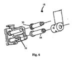
図6は、投与量カウンタ18の分解図を示し、前記した部品に加えて、スプリットハブ(split hub)70の作用によって緊張保持されるストックボビン68を示す。スプリットハブ70は、WO98/28033に記載されたようなクラッチスプリングを不要とする。クラッチスプリングは、スプリットハブ70の代替又は追加として使用され得るが、好ましい実施形態では、本発明の投与量カウンタは、クラッチスプリングを備えていない。ディスプレイは、好ましくは長いカウンタテープ44であり、投与量カウントが印刷又は書き込まれている。更に好ましくは、カウンタテープ44は、インデックススプールに配置されており、投与量カウンタは、更にストックボビンを備え、インデックススプールが段階的に前進する時にカウンタテープを収納する。
FIG. 6 shows an exploded view of the
使用中における、投与量カウンタ18の作動は次の通りである。
The operation of the
使用者は、アクチュエータ20の移動を生じさせるエアロゾルキャニスター6を押下げる。本実施形態では、アクチュエータ20は、薬剤キャニスター6のリムに係合するように構成される。アクチュエータ20は、第一位置から第二位置そして第一位置へ戻る直線移動によって作動し、第一位置から第二位置へアクチュエータが移動する間、又は第二位置から第一位置へアクチュエータが移動する間において、ロータリーギアの移動が生じる。図5に示す実施形態では、第一位置から第二位置へアクチュエータが移動する間に、ロータリーギアの移動が生じる。実施形態に示すように、アクチュエータ20は、スプリングで負荷されたプランジャ22,24を備え、薬剤投与を搬送するためにアクチュエータを起動させるとき、スプリング負荷の戻り力に反してプランジャを押下げ可能になっている。
The user pushes down the
第一位置から第二位置へ移動する間、アクチュエータ20は、ドライバ28をホイール30のラチェット歯32の後縁62に係合させる。アクチュエータ20とドライバ28が下降すると、ラチェット歯ホイール30が回転する。
While moving from the first position to the second position, the
ロータリーギアのスピンドルは、カウンタテープ44を移動して次の数を示す。カウンタテープ44は、ストックボビン68が設けられたスプリットハブ70の作用で緊張保持される。
The spindle of the rotary gear moves the
歯止め60が半径方向外側に変形すると、ホイール30が一つの歯32ごとに回転可能になる。歯止め60の少なくとも二つの歯64,66は、本質的に弾性を有しており、必要な半径方向外側の変形及び復帰を可能とする。代替的又は追加的に、歯止め60は、半径方向外側に変形可能な弾性サポートに設けられることができ、例えば、弾性サポートは、投与量カウンタ18のシャシに組み込まれた弾性フランジとすることができる。
When the
ラチェット歯ホイール30が歯止め60と係合した後、ドライバ28は、ラチェット歯ホイール30を解放する。吸入器をリセットすると、キャニスター6は、初期位置(第一位置)へ戻ることができる。圧縮バネ24は、キャニスターに続くためにアクチュエータ20を押す。アクチュエータ20が第一位置から第二位置へ移動するとき、アクチュエータ20上のドライバ28は、曲がって、ラチェット歯ホイール30の歯を通り過ぎる。
After the
ホイール30の歯32に係合した少なくとも二つの歯64,66は、ロータリーギアの逆回転を防止する。
At least two
WO98/28033及び本発明に関して記載されたタイプのカウンタ機構は、アクチュエータが押下げられるたびに、正確な一つの歯のスペースごとにロータリーギアのホイール30を回転しなければならない。歯のスペースごととは、一つの歯のピッチ、即ち、ラチェット歯ホイール30における二つの近接する歯32の同一仮想ポイントの間での放射距離、を意味している。ロータリーギアをインデックスするために利用可能なストロークは、アクチュエータ2の全ストロークに等しい。計量式吸入器が加圧式吸入器の場合、カウントするために利用可能なストロークは、薬剤キャニスター6の全ストロークに等しい。しかし、投与量カウンタをインデックスするため、全行程で完了しなければならない3つの運動(又は移動)がある。3つの移動を図7で概略的に示す。
A counter mechanism of the type described with respect to WO 98/28033 and the present invention must rotate the
図7は、キャニスター移動の総量、そして3つの重要な移動が生じる前に利用可能な余分のストロークについての、グラフ表示を示す。第一に、キャニスター移動は、垂直方向における製作部品の許容誤差の総量であるスタートギャップを縮める。第二に、ストロークは、例えば、旋回移動における歯止めの屈曲及びドライブ歯止めの円弧運動のような空動きを縮める。第三に、所謂「カウントのためのストローク」があり、一つの歯の間隔ごとにロータリーギアのインデックスを導く移動である。 FIG. 7 shows a graphical representation of the total amount of canister movement and the extra stroke available before three significant movements occur. First, canister movement shortens the start gap, which is the total amount of tolerance of manufactured parts in the vertical direction. Secondly, the stroke reduces idle movements such as pawl bending and drive pawl arcing in swiveling movements, for example. Thirdly, there is a so-called “stroke for counting”, which is a movement for guiding the index of the rotary gear at intervals of one tooth.
カウントに利用可能なストロークは、明らかに、使用される計量式吸入器のタイプに依存する。例えば、好適な吸入器として、Qvar(登録商標)のキャニスターを用いたEasiBreathe(登録商標)の加圧計量式吸入器がある。この吸入器におけるキャニスターストロークは、3.04±0.255mmと測定される。この許容誤差は、±3標準偏差で表され、全キャニスターストロークの99.7%が、これらの範囲内となる。測定は、Qvar(登録商標)のキャニスターにおける力対変位の分析結果から得られた。150のキャニスターが、寿命の初期、中期及び末期において測定され、総計450ストロークの測定結果を提供する。 The stroke available for counting obviously depends on the type of metered inhaler used. For example, a suitable inhaler is an EasiBreathe® pressurized metered dose inhaler using a Qvar® canister. The canister stroke in this inhaler is measured as 3.04 ± 0.255 mm. This tolerance is expressed as ± 3 standard deviations, and 99.7% of all canister strokes fall within these ranges. Measurements were obtained from the analysis of force versus displacement in a Qvar® canister. 150 canisters are measured at the beginning, middle and end of life, providing a total of 450 stroke measurements.
スタートギャップは、垂直方向における許容誤差の積み重ねであって、ホイール30に係合するドライバ28の部分とロータリーギアのホイール30の好適なラチェット歯32との間の第一の距離と、アクチュエータ20の頂面とキャニスター6との間の第二の距離と、を含む。垂直方向における許容誤差は、±0.47mmと確認された。EasiBreathe(登録商標)の吸入器における公称スタートギャップは、0.85mmで設定されるので、許容誤差を含むスタートギャップは、0.85±0.47mmである。
The start gap is a stack of tolerances in the vertical direction, the first distance between the portion of the
従って、スタートギャップが0.85±0.47mmであるので、最大スタートギャップ(3標準偏差を加えるという意味)は、1.32mm(0.85+0.47)である。このようなスタートギャップが生じるとき、短ストロークのキャニスター(例えば、2.79mm)では、最大の歯のスペースによって、ロータリーギアのホイール30を回転しない。これは、投与量カウンタの不成功を導く。しかし、歯止め60における第一及び第二のラチェット歯64,66を提供することで、ロータリーギアのホイール30のラチェット歯32が、第二の歯66に留まるようにできる。本実施形態では、第二の歯66は、第一の歯64から0.6mm離れている。従って、次の駆動のために、スタートギャップは、0.72mm(1.32−0.60)に減少される。従って、ストロークは、ホイール30を回転するのに十分であり、完全なインデックス(full index)がこの点から開始する。その後、ホイール30の段階的回転が、歯止め60の第二の歯66に係合されたロータリーギアのホイール30のラチェット歯32から開始及び終了して、全ての連続駆動を続ける。
Therefore, since the start gap is 0.85 ± 0.47 mm, the maximum start gap (meaning adding 3 standard deviations) is 1.32 mm (0.85 + 0.47). When such a start gap occurs, a short stroke canister (eg 2.79 mm) does not rotate the
図8は、ロータリーギアの逆回転を防止するためのロータリーギアのホイール30、ドライバ28及び歯止め60を更に詳細に示す。図8(a)では、ホイール30のラチェット歯32aが、歯止めの第1のラチェット歯64に係合する。図8(b)では、ホイール30の同一歯32aが、歯止め60の第二のラチェット歯66に係合する。スタートギャップは、図8(a)における同一距離と比較して図8(b)での配置では、減少されていることが理解できる。従って、歯止め60の第二の歯66は、スタートギャップの第一の距離S(ホイール30に係合するドライバ28の部分とホイール30の好適な歯32との間)を減少させ、これによって、キャニスターストロークにおけるより大きな許容誤差を調整する。
FIG. 8 shows the
上記で説明したように、第一及び第二の歯64,66は、ロータリーギアのホイール30に対して異なるスタート位置を提供し、吸入器の部品における異なる許容誤差レベルを調整する。従って、歯64,66は、ホイール30に関して放射方向に分離されている。間隔は、吸入器において使用される部品の特質に依存しているので、正確な数値を提供することは不適切である。しかし、機構から明らかなように、放射間隔は、ロータリーギアのホイール30における近接する歯32間の放射距離より短い。
As explained above, the first and
ここで示す実施形態において、本発明の投与量カウンタ18は、二つの歯64,66を有する歯止め60を組み込み、歯止め60は、実質的に二つの歯64,66からなる。しかし、ホイール30のスタート位置に対する精度を増加、即ち第一の距離Sにおける精度を増加するために、追加歯を組み込むことができる。例えば、歯止めは、2〜6、好ましくは、2,3又は4本の歯、更に好ましくは2又は3、最も好ましくは2本の歯を有することができる。
In the embodiment shown, the
本発明の特に好ましい実施形態では、投与量カウンタは、3.041±0.256mmのキャニスターストロークが提供され、ロータリーギアのホイールは、ホイールの中心から歯の先端までの距離として規定される2.80±0.05mmの半径と、周囲に11のラチェット歯とを有し、歯止めは、0.6mmの放射距離を有する二つのラチェット歯を備える。この実施形態では、カウントを保障する全ストロークは、2.372±0.115mmである。カウントの不成功又は部品の寸法誤差(製作許容誤差)による不快感の可能性は、1000万分の1より小さい。 In a particularly preferred embodiment of the invention, the dose counter is provided with a canister stroke of 3.041 ± 0.256 mm, and the wheel of the rotary gear is defined as the distance from the center of the wheel to the tooth tip. With a radius of 80 ± 0.05 mm and 11 ratchet teeth around the perimeter, the pawl comprises two ratchet teeth with a radial distance of 0.6 mm. In this embodiment, the total stroke ensuring the count is 2.372 ± 0.115 mm. The potential for discomfort due to unsuccessful counting or part dimensional errors (manufacturing tolerances) is less than 1 in 10 million.
本発明は、更に、図9に示すような計量式吸入器を提供する。吸入器は、薬剤キャニスター6と、キャニスターを収容すると共に薬剤排出口を有するアクチュエータ本体74と、上記した投与量カウンタとを備える。吸入器は、テープ44上の数字を見るためのウインドウ76を備える。好ましい実施形態では、アクチュエータ本体74は、サンプ(sump)、好ましくは滑らかな曲面のサンプからなる。一般に、曲面サンプは、実質円筒状の上部と、実質半球状の下部とを備える。一般に、滑らかとは、通常の使用時において、薬剤が実質的に付着しない程度に表面が突出していないことを意味する。
The present invention further provides a metered dose inhaler as shown in FIG. The inhaler includes a
発明の一実施形態において、容器は、エアロゾル形式の薬剤を収容する。また、発明の他の実施形態では、容器は、ドライパウダー形式の薬剤を収容する。 In one embodiment of the invention, the container contains an aerosol-type drug. In another embodiment of the invention, the container contains a drug in the form of a dry powder.
薬剤は、吸入器を介して患者に搬送されるのに適した薬剤が可能である。特に、広範囲の様々な呼吸器疾患を治療するための薬剤が、抗アレルギー薬(例えば、クロモグリケイト、ケトチフェン及びネドクロシル)、抗炎症薬ステロイド(例えば、ベクロメタゾン・ニプロピオン酸塩、フルチカゾン、ブアソンド、フルニソリド、シクレソンド、トリアムミノロンアセトンド及びモメタゾンフロ酸エステル)、気管支援拡張剤、例えば、β2アゴニスト(例えば、フェノテロール、ホルモテロール、ピルブテロール、レプロテロール、サルブタモール、サルメテロール及びテルブタリン)、非選択的なβ興奮剤(例えば、イソプレナリン)、及びキサンチン気管支援拡張剤(例えば、テオフィリン、アミノフィリン及びコリンテオフィリン)、そして、抗コリン剤(例えば、臭化イプラトロピウム、臭化キシトロピウム及びチオトロピウム)を含む方法で搬送される。 The drug can be a drug suitable for delivery to a patient via an inhaler. In particular, drugs for treating a wide variety of respiratory diseases include antiallergic drugs (eg cromoglycate, ketotifen and nedocrosyl), anti-inflammatory steroids (eg beclomethasone nipropionate, fluticasone, buasondo, Flunisolide, ciclesond, triamminolone acetone and mometasone furoate), bronchial support dilators, such as β2 agonists (eg fenoterol, formoterol, pyrbuterol, reproterol, salbutamol, salmeterol and terbutaline), non-selective β stimulants (Eg, isoprenaline), and xanthine bronchial assisting dilators (eg, theophylline, aminophylline and choline theophylline), and anticholinergic agents (eg, ipratropium bromide, xytropio bromide) And it is conveyed by a method comprising tiotropium).
本発明の更なる側面では、計量式吸入器72の投与量カウンタにおいて、ミスカウントを防止するための少なくとも二つのラチェット歯64,66を備える歯止め60の使用を提供する。本発明の更なる側面では、計量式吸入器72のカウンタにおいて、数え落としを防止するための少なくとも二つのラチェット歯64,66を備える歯止め60の使用を提供する。
In a further aspect of the present invention, the use of
好ましい実施形態では、カウンタは、アクチュエータ20と、ロータリーギアと、アクチュエータの移動に応答して段階的にロータリーギアを駆動するためのドライバ28と、を備える。ロータリーギアは、スピンドル36に設けられたホイール30を備え、ホイール30は、周囲に複数のラチェット歯32を備える。カウンタは、ロータリーギアに連結されたディスプレイ44を備え、ディスプレイは、ロータリーギアの段階的回転移動の各ステップに応答する単一整数でインデックス可能なように、表面に個数が増加する整数の一覧列挙を備える。好ましくは、歯止め60は、ロータリーギアの逆回転を防止する。
In a preferred embodiment, the counter comprises an
本発明について個々の実施形態に基づいて記載したが、これらの実施形態は、本発明の単なる原理及び応用の説明であることが理解される。従って、種々の変形例が、実施形態として説明され、その他の装置が、請求の範囲に規定される本発明の精神と範囲を逸脱することなく発明され得ることが理解される。 Although the invention has been described with reference to particular embodiments, it will be understood that these embodiments are merely illustrative of the principles and applications of the invention. Accordingly, it will be understood that various modifications are described as embodiments, and that other devices may be invented without departing from the spirit and scope of the invention as defined in the claims.
Claims (17)
アクチュエータ(20)と、
ロータリーギア(30)と、
前記アクチュエータ(20)の移動に応答して段階的に前記ロータリーギア(30)を駆動するためのドライバ(28)と、を備え、前記ロータリーギア(30)は、スピンドルに設けられたホイールを備え、前記ホイールは、周囲に複数のラチェット歯(32)を備え、
前記カウンタは、さらに、
前記ロータリーギア(30)の逆回転を制止するための歯止め(60)と、
前記ロータリーギア(30)に連結されたディスプレイ(44)と、を備え、前記ディスプレイ(44)は、その表面に個数が増加する整数の一覧列挙を備え、
前記ディスプレイ(44)は、さらに、前記ロータリーギア(30)の段階的回転移動の各ステップに応答する単一整数でインデックス可能になっており、
前記歯止め(60)は、放射状に間隔を置いて少なくとも二つのラチェット歯(64,66)を備えており、前記歯(64,66)のいずれか一つであって、そのいずれか一つの歯(64又は66)に、前記ロータリーギアの段階的回転移動の各ステップに追随するホイールのラチェット歯が係合するようになっており、
前記計量式吸入器は、薬剤キャニスターと、前記キャニスターを収容すると共に薬剤排出口を有するアクチュエータ本体と、前記投与量カウンタと、を備えることを特徴とする。 In a dose counter for a metered dose inhaler, the counter is
An actuator (20) ;
Rotary gear (30) ;
Comprising a driver (28) for driving stepwise the rotary gear (30) in response to movement of said actuator (20), said rotary gear (30) comprises a wheel provided on the spindle , the wheel is provided with ratchet teeth (32) a plurality of surrounding,
The counter further includes:
Pawl for arresting the reverse rotation of said rotary gear (30) and (60),
Wherein the concatenated display (44) to the rotary gear (30), wherein the display (44) is provided with a list integer enumeration number increases to its front surface,
The display (44) is further indexable by a single integer responsive to each step of the stepwise rotational movement of the rotary gear (30);
The pawl (60) includes at least two ratchet teeth (64, 66) spaced radially from each other, and is any one of the teeth (64, 66). (64 or 66), and the ratchet teeth of the wheel to follow the steps of the stepwise rotational movement of the rotary gear adapted to be engaged,
The metering inhaler includes a drug canister, an actuator body that houses the canister and has a drug discharge port, and the dose counter .
Applications Claiming Priority (5)
| Application Number | Priority Date | Filing Date | Title |
|---|---|---|---|
| US92132007P | 2007-04-02 | 2007-04-02 | |
| US60/921,320 | 2007-04-02 | ||
| GBGB0706999.0A GB0706999D0 (en) | 2007-04-11 | 2007-04-11 | Metered-dose inhaler |
| GB0706999.0 | 2007-04-11 | ||
| PCT/EP2008/002590 WO2008119552A1 (en) | 2007-04-02 | 2008-04-01 | Metered-dose inhaler |
Publications (2)
| Publication Number | Publication Date |
|---|---|
| JP2010523184A JP2010523184A (en) | 2010-07-15 |
| JP5246968B2 true JP5246968B2 (en) | 2013-07-24 |
Family
ID=38091187
Family Applications (1)
| Application Number | Title | Priority Date | Filing Date |
|---|---|---|---|
| JP2010501422A Active JP5246968B2 (en) | 2007-04-02 | 2008-04-01 | Metered inhaler |
Country Status (18)
| Country | Link |
|---|---|
| US (1) | US8132712B2 (en) |
| EP (1) | EP2135199B1 (en) |
| JP (1) | JP5246968B2 (en) |
| KR (1) | KR101475968B1 (en) |
| CN (1) | CN101657829B (en) |
| AT (1) | ATE556386T1 (en) |
| AU (1) | AU2008234098B2 (en) |
| BR (1) | BRPI0809477A2 (en) |
| CA (1) | CA2682528C (en) |
| DK (1) | DK2135199T3 (en) |
| EA (1) | EA016831B1 (en) |
| ES (1) | ES2404818T3 (en) |
| GB (1) | GB0706999D0 (en) |
| HK (1) | HK1141349A1 (en) |
| IL (1) | IL201256A (en) |
| MX (1) | MX2009010600A (en) |
| PT (1) | PT2135199E (en) |
| WO (1) | WO2008119552A1 (en) |
Families Citing this family (26)
| Publication number | Priority date | Publication date | Assignee | Title |
|---|---|---|---|---|
| JP4423457B2 (en) * | 1998-01-16 | 2010-03-03 | トルーデル メディカル インターナショナル | Dispenser and administration device display device |
| FR2854878B1 (en) * | 2003-05-15 | 2006-03-31 | Valois Sas | FLUID PRODUCT DISPENSER. |
| GB0425518D0 (en) | 2004-11-19 | 2004-12-22 | Clinical Designs Ltd | Substance source |
| GB0518400D0 (en) | 2005-09-09 | 2005-10-19 | Clinical Designs Ltd | Dispenser |
| GB0904040D0 (en) | 2009-03-10 | 2009-04-22 | Euro Celtique Sa | Counter |
| GB0904059D0 (en) | 2009-03-10 | 2009-04-22 | Euro Celtique Sa | Counter |
| GB0910537D0 (en) | 2009-06-18 | 2009-07-29 | Ivax Pharmaceuticals Ireland | Inhaler |
| EP2705868B8 (en) * | 2009-07-30 | 2015-11-25 | Ivax International B.V. | Dose counter for a metered-dose inhaler |
| US9216261B2 (en) | 2009-07-30 | 2015-12-22 | Ivax International B.V. | Dose counter for a metered-dose inhaler |
| CN105903111B (en) * | 2010-05-18 | 2019-06-25 | 艾瓦克斯医药爱尔兰公司 | Dose counter, inhalator and its axis for inhalator |
| AU2013231211B2 (en) * | 2010-05-18 | 2015-11-19 | Ivax Pharmaceuticals Ireland | Dose counters for inhalers, inhalers and shafts thereof |
| EA024597B1 (en) * | 2010-05-18 | 2016-10-31 | Ивакс Фармасьютикалз Аэрлэнд | Method for designing incremental dose counter for inhaler, computer method for designing the same and method for mass production thereof |
| FR2974410B1 (en) * | 2011-04-22 | 2015-05-29 | France Etat | PASSIVE AND REVERSIBLE DEFORMATION SENSOR |
| US8746241B2 (en) | 2011-10-03 | 2014-06-10 | Sabrina B. Cavendish | Combination MDI and nebulizer adapter for a ventilator system |
| GB2502791B (en) | 2012-06-06 | 2014-08-20 | Consort Medical Plc | Dose indicator device |
| GB201406046D0 (en) * | 2014-04-03 | 2014-05-21 | 3M Innovative Properties Co | Dose indicator or dose counter |
| DE102014118325A1 (en) * | 2014-12-10 | 2016-06-16 | Alfred Von Schuckmann | counter |
| KR101651264B1 (en) * | 2015-04-07 | 2016-09-06 | 주식회사 디복스 | Drive Apparatus Of Volatile Organic Compound Combustion System |
| CN106051795A (en) * | 2015-04-07 | 2016-10-26 | 株式会社德福喜 | Drive device for volatile organic compound combustion system |
| GB201702408D0 (en) | 2017-02-14 | 2017-03-29 | Norton (Waterford) Ltd | Inhalers and related methods |
| GB201702406D0 (en) | 2017-02-14 | 2017-03-29 | Norton (Waterford) Ltd | Inhalers and related methods |
| GB201702407D0 (en) | 2017-02-14 | 2017-03-29 | Norton (Waterford) Ltd | Inhalers and related methods |
| GB201801309D0 (en) | 2018-01-26 | 2018-03-14 | Norton Waterford Ltd | Breath actuated inhaler |
| CN111605875A (en) * | 2020-06-04 | 2020-09-01 | 重庆工业职业技术学院 | Logistics safety box |
| WO2023094551A1 (en) | 2021-11-24 | 2023-06-01 | Norton (Waterford) Limited | Drug delivery device with electronics |
| CN114558210B (en) * | 2022-03-04 | 2023-11-07 | 上海华瑞气雾剂有限公司 | Driver with spraying frequency indication and method |
Family Cites Families (17)
| Publication number | Priority date | Publication date | Assignee | Title |
|---|---|---|---|---|
| US4445404A (en) * | 1981-12-09 | 1984-05-01 | Bob Barber, Jr. | Reversible ratchet wrench |
| JP2574488Y2 (en) * | 1992-09-07 | 1998-06-11 | 芦森工業株式会社 | Seat belt retractor |
| US5489143A (en) * | 1993-09-06 | 1996-02-06 | Suncall Corporation | Arm rest device |
| JP3436432B2 (en) * | 1995-01-27 | 2003-08-11 | 株式会社東海理化電機製作所 | Reverse movement prevention device |
| US5490749A (en) * | 1995-02-22 | 1996-02-13 | Arbues; Jose L. A. | Winch construction for cargo tie-down straps |
| EP0809950B1 (en) * | 1996-05-30 | 2002-04-17 | Bauer Italia S.p.A. | A device for adjusting and clamping the toothed strap of a fastening for sports footwear |
| GB2320489A (en) | 1996-12-20 | 1998-06-24 | Norton Healthcare Ltd | Inhaler dose counter |
| JPH1184515A (en) * | 1997-07-18 | 1999-03-26 | Fuji Photo Film Co Ltd | Counter mechanism for sheet film pack |
| US6226627B1 (en) * | 1998-04-17 | 2001-05-01 | Fuji Xerox Co., Ltd. | Method and system for constructing adaptive and resilient software |
| US6070502A (en) * | 1998-12-31 | 2000-06-06 | Chang; Jui-Ling | Ratchet box wrench |
| GB2347900A (en) * | 1999-03-15 | 2000-09-20 | Breed Automotive Tech | Seat Belt Retractor |
| GB2364649A (en) * | 2000-05-17 | 2002-02-06 | Orion Corp | Inhaler with Dose Counter |
| JP4241613B2 (en) * | 2002-06-12 | 2009-03-18 | ベーリンガー インゲルハイム マイクロパーツ ゲゼルシャフト ミット ベシュレンクテル ハフツング | Counting device for counting metered delivery of liquid, pasty or solid products and device for metering and delivering such products |
| FR2858867B1 (en) * | 2003-08-12 | 2005-11-04 | Valois Sa | DOSING INDICATOR FOR FLUID PRODUCT DISPENSING DEVICE |
| WO2005114563A1 (en) | 2004-04-29 | 2005-12-01 | Valois Sas | Indicator for a device for dispensing a liquid or powdery product |
| US7252065B1 (en) * | 2006-05-11 | 2007-08-07 | Husqvarna Outdoor Products Inc. | Energy storing starting device |
| US20110220450A1 (en) * | 2010-03-09 | 2011-09-15 | Joy Industrial Co., Ltd. | Hub ratchet driving device for bicycles |
-
2007
- 2007-04-11 GB GBGB0706999.0A patent/GB0706999D0/en not_active Ceased
-
2008
- 2008-04-01 US US12/532,762 patent/US8132712B2/en active Active
- 2008-04-01 JP JP2010501422A patent/JP5246968B2/en active Active
- 2008-04-01 EP EP08734940A patent/EP2135199B1/en active Active
- 2008-04-01 MX MX2009010600A patent/MX2009010600A/en active IP Right Grant
- 2008-04-01 PT PT87349403T patent/PT2135199E/en unknown
- 2008-04-01 AT AT08734940T patent/ATE556386T1/en active
- 2008-04-01 CN CN2008800108377A patent/CN101657829B/en not_active Expired - Fee Related
- 2008-04-01 WO PCT/EP2008/002590 patent/WO2008119552A1/en active Application Filing
- 2008-04-01 BR BRPI0809477-2A patent/BRPI0809477A2/en not_active Application Discontinuation
- 2008-04-01 EA EA200970907A patent/EA016831B1/en not_active IP Right Cessation
- 2008-04-01 CA CA2682528A patent/CA2682528C/en active Active
- 2008-04-01 KR KR1020097022883A patent/KR101475968B1/en active IP Right Grant
- 2008-04-01 AU AU2008234098A patent/AU2008234098B2/en not_active Ceased
- 2008-04-01 DK DK08734940.3T patent/DK2135199T3/en active
- 2008-04-01 ES ES08734940T patent/ES2404818T3/en active Active
-
2009
- 2009-09-30 IL IL201256A patent/IL201256A/en active IP Right Grant
-
2010
- 2010-08-16 HK HK10107779.0A patent/HK1141349A1/en not_active IP Right Cessation
Also Published As
| Publication number | Publication date |
|---|---|
| IL201256A0 (en) | 2010-05-31 |
| EA016831B1 (en) | 2012-07-30 |
| CN101657829B (en) | 2013-05-29 |
| MX2009010600A (en) | 2009-12-16 |
| AU2008234098B2 (en) | 2012-06-07 |
| BRPI0809477A2 (en) | 2014-09-09 |
| ES2404818T3 (en) | 2013-05-29 |
| HK1141349A1 (en) | 2010-11-05 |
| EP2135199B1 (en) | 2012-05-02 |
| GB0706999D0 (en) | 2007-05-16 |
| CA2682528A1 (en) | 2008-10-09 |
| PT2135199E (en) | 2013-03-27 |
| ATE556386T1 (en) | 2012-05-15 |
| JP2010523184A (en) | 2010-07-15 |
| KR20090127376A (en) | 2009-12-10 |
| CN101657829A (en) | 2010-02-24 |
| WO2008119552A1 (en) | 2008-10-09 |
| IL201256A (en) | 2014-11-30 |
| US20100078490A1 (en) | 2010-04-01 |
| CA2682528C (en) | 2014-09-02 |
| EA200970907A1 (en) | 2010-04-30 |
| KR101475968B1 (en) | 2014-12-23 |
| US8132712B2 (en) | 2012-03-13 |
| AU2008234098A1 (en) | 2008-10-09 |
| DK2135199T3 (en) | 2013-04-02 |
| EP2135199A1 (en) | 2009-12-23 |
Similar Documents
| Publication | Publication Date | Title |
|---|---|---|
| JP5246968B2 (en) | Metered inhaler | |
| JP5657659B2 (en) | Dose counter for metered dose inhalers | |
| AU2013224758B2 (en) | Dose counter for a metered-dose inhaler |
Legal Events
| Date | Code | Title | Description |
|---|---|---|---|
| A621 | Written request for application examination |
Free format text: JAPANESE INTERMEDIATE CODE: A621 Effective date: 20110203 |
|
| A977 | Report on retrieval |
Free format text: JAPANESE INTERMEDIATE CODE: A971007 Effective date: 20120726 |
|
| A131 | Notification of reasons for refusal |
Free format text: JAPANESE INTERMEDIATE CODE: A131 Effective date: 20120801 |
|
| A521 | Request for written amendment filed |
Free format text: JAPANESE INTERMEDIATE CODE: A523 Effective date: 20121017 |
|
| TRDD | Decision of grant or rejection written | ||
| A01 | Written decision to grant a patent or to grant a registration (utility model) |
Free format text: JAPANESE INTERMEDIATE CODE: A01 Effective date: 20130403 |
|
| A61 | First payment of annual fees (during grant procedure) |
Free format text: JAPANESE INTERMEDIATE CODE: A61 Effective date: 20130408 |
|
| R150 | Certificate of patent or registration of utility model |
Free format text: JAPANESE INTERMEDIATE CODE: R150 |
|
| FPAY | Renewal fee payment (event date is renewal date of database) |
Free format text: PAYMENT UNTIL: 20160419 Year of fee payment: 3 |
|
| R250 | Receipt of annual fees |
Free format text: JAPANESE INTERMEDIATE CODE: R250 |
|
| R250 | Receipt of annual fees |
Free format text: JAPANESE INTERMEDIATE CODE: R250 |
|
| R250 | Receipt of annual fees |
Free format text: JAPANESE INTERMEDIATE CODE: R250 |
|
| R250 | Receipt of annual fees |
Free format text: JAPANESE INTERMEDIATE CODE: R250 |