JP5243034B2 - Tissue removal device - Google Patents
Tissue removal device Download PDFInfo
- Publication number
- JP5243034B2 JP5243034B2 JP2007536970A JP2007536970A JP5243034B2 JP 5243034 B2 JP5243034 B2 JP 5243034B2 JP 2007536970 A JP2007536970 A JP 2007536970A JP 2007536970 A JP2007536970 A JP 2007536970A JP 5243034 B2 JP5243034 B2 JP 5243034B2
- Authority
- JP
- Japan
- Prior art keywords
- tissue
- exfoliation
- nerve
- needle
- tissue removal
- Prior art date
- Legal status (The legal status is an assumption and is not a legal conclusion. Google has not performed a legal analysis and makes no representation as to the accuracy of the status listed.)
- Expired - Fee Related
Links
- 238000000034 method Methods 0.000 claims abstract description 234
- 238000005520 cutting process Methods 0.000 claims abstract description 59
- 230000001537 neural effect Effects 0.000 claims abstract description 53
- 238000012986 modification Methods 0.000 claims abstract description 18
- 230000004048 modification Effects 0.000 claims abstract description 18
- 210000001519 tissue Anatomy 0.000 claims description 1167
- 210000005036 nerve Anatomy 0.000 claims description 436
- 238000004299 exfoliation Methods 0.000 claims description 254
- 230000000638 stimulation Effects 0.000 claims description 59
- 210000000988 bone and bone Anatomy 0.000 claims description 40
- 210000004872 soft tissue Anatomy 0.000 claims description 20
- 238000002679 ablation Methods 0.000 claims description 19
- 230000001050 lubricating effect Effects 0.000 claims description 2
- 230000004888 barrier function Effects 0.000 abstract description 199
- 230000001681 protective effect Effects 0.000 abstract description 56
- 238000001356 surgical procedure Methods 0.000 abstract description 54
- 230000002792 vascular Effects 0.000 abstract description 17
- 238000005299 abrasion Methods 0.000 abstract description 8
- 230000004224 protection Effects 0.000 description 188
- 230000006835 compression Effects 0.000 description 69
- 238000007906 compression Methods 0.000 description 69
- 230000000324 neuroprotective effect Effects 0.000 description 59
- 230000007383 nerve stimulation Effects 0.000 description 49
- 210000002517 zygapophyseal joint Anatomy 0.000 description 44
- 239000000523 sample Substances 0.000 description 43
- 238000013459 approach Methods 0.000 description 39
- 230000006378 damage Effects 0.000 description 38
- 210000003041 ligament Anatomy 0.000 description 36
- 238000009434 installation Methods 0.000 description 35
- 210000004749 ligamentum flavum Anatomy 0.000 description 35
- 238000012544 monitoring process Methods 0.000 description 32
- 230000003040 nociceptive effect Effects 0.000 description 30
- 238000007634 remodeling Methods 0.000 description 30
- 210000003484 anatomy Anatomy 0.000 description 25
- 230000008569 process Effects 0.000 description 25
- 238000012800 visualization Methods 0.000 description 25
- 238000000576 coating method Methods 0.000 description 23
- 239000000463 material Substances 0.000 description 23
- 210000001032 spinal nerve Anatomy 0.000 description 22
- 239000011248 coating agent Substances 0.000 description 21
- 230000004807 localization Effects 0.000 description 21
- 241001269524 Dura Species 0.000 description 19
- 239000013307 optical fiber Substances 0.000 description 19
- 230000007838 tissue remodeling Effects 0.000 description 19
- 230000008859 change Effects 0.000 description 18
- 239000003814 drug Substances 0.000 description 17
- 208000005198 spinal stenosis Diseases 0.000 description 17
- 230000009545 invasion Effects 0.000 description 16
- 238000002271 resection Methods 0.000 description 16
- 238000011282 treatment Methods 0.000 description 16
- 239000000835 fiber Substances 0.000 description 15
- 239000012530 fluid Substances 0.000 description 15
- 238000012360 testing method Methods 0.000 description 15
- 210000004204 blood vessel Anatomy 0.000 description 14
- 230000004927 fusion Effects 0.000 description 14
- 230000007246 mechanism Effects 0.000 description 14
- 230000000763 evoking effect Effects 0.000 description 13
- 238000003780 insertion Methods 0.000 description 13
- 230000037431 insertion Effects 0.000 description 13
- 230000033001 locomotion Effects 0.000 description 13
- 230000001575 pathological effect Effects 0.000 description 13
- 230000004044 response Effects 0.000 description 13
- 229940079593 drug Drugs 0.000 description 12
- 230000037361 pathway Effects 0.000 description 12
- 230000001953 sensory effect Effects 0.000 description 12
- 238000012790 confirmation Methods 0.000 description 11
- 230000000916 dilatatory effect Effects 0.000 description 11
- 230000009977 dual effect Effects 0.000 description 10
- 230000006870 function Effects 0.000 description 10
- 238000004080 punching Methods 0.000 description 10
- 238000002604 ultrasonography Methods 0.000 description 10
- 238000004891 communication Methods 0.000 description 9
- 230000006837 decompression Effects 0.000 description 9
- 238000002594 fluoroscopy Methods 0.000 description 9
- 230000023597 hemostasis Effects 0.000 description 9
- 230000000926 neurological effect Effects 0.000 description 9
- 210000000278 spinal cord Anatomy 0.000 description 9
- 208000008558 Osteophyte Diseases 0.000 description 8
- 230000001010 compromised effect Effects 0.000 description 8
- 210000001951 dura mater Anatomy 0.000 description 8
- 230000003447 ipsilateral effect Effects 0.000 description 8
- -1 poly (tetrafluoroethylene) Polymers 0.000 description 8
- 210000003594 spinal ganglia Anatomy 0.000 description 8
- 208000024891 symptom Diseases 0.000 description 8
- 208000002847 Surgical Wound Diseases 0.000 description 7
- 238000006243 chemical reaction Methods 0.000 description 7
- 230000005611 electricity Effects 0.000 description 7
- 230000004112 neuroprotection Effects 0.000 description 7
- 229920000642 polymer Polymers 0.000 description 7
- 229920001343 polytetrafluoroethylene Polymers 0.000 description 7
- 230000002633 protecting effect Effects 0.000 description 7
- 150000003431 steroids Chemical class 0.000 description 7
- 239000004593 Epoxy Substances 0.000 description 6
- 208000028389 Nerve injury Diseases 0.000 description 6
- 208000002193 Pain Diseases 0.000 description 6
- 239000004020 conductor Substances 0.000 description 6
- 229910003460 diamond Inorganic materials 0.000 description 6
- 239000010432 diamond Substances 0.000 description 6
- 230000010339 dilation Effects 0.000 description 6
- 239000012634 fragment Substances 0.000 description 6
- 230000035876 healing Effects 0.000 description 6
- 230000001965 increasing effect Effects 0.000 description 6
- 210000001503 joint Anatomy 0.000 description 6
- 230000008764 nerve damage Effects 0.000 description 6
- 230000036407 pain Effects 0.000 description 6
- 230000036961 partial effect Effects 0.000 description 6
- 230000003238 somatosensory effect Effects 0.000 description 6
- 230000000451 tissue damage Effects 0.000 description 6
- 231100000827 tissue damage Toxicity 0.000 description 6
- 230000000007 visual effect Effects 0.000 description 6
- 208000003098 Ganglion Cysts Diseases 0.000 description 5
- 206010061218 Inflammation Diseases 0.000 description 5
- 208000031481 Pathologic Constriction Diseases 0.000 description 5
- 208000005400 Synovial Cyst Diseases 0.000 description 5
- 230000000740 bleeding effect Effects 0.000 description 5
- 230000008468 bone growth Effects 0.000 description 5
- 235000013351 cheese Nutrition 0.000 description 5
- 238000003486 chemical etching Methods 0.000 description 5
- 238000004140 cleaning Methods 0.000 description 5
- 238000013461 design Methods 0.000 description 5
- 238000010586 diagram Methods 0.000 description 5
- 238000000227 grinding Methods 0.000 description 5
- 230000004054 inflammatory process Effects 0.000 description 5
- 239000011159 matrix material Substances 0.000 description 5
- 229910052751 metal Inorganic materials 0.000 description 5
- 239000002184 metal Substances 0.000 description 5
- 210000003205 muscle Anatomy 0.000 description 5
- 210000000944 nerve tissue Anatomy 0.000 description 5
- 229910001000 nickel titanium Inorganic materials 0.000 description 5
- 239000013641 positive control Substances 0.000 description 5
- 230000002285 radioactive effect Effects 0.000 description 5
- 231100000241 scar Toxicity 0.000 description 5
- 230000035807 sensation Effects 0.000 description 5
- 239000007787 solid Substances 0.000 description 5
- 210000000273 spinal nerve root Anatomy 0.000 description 5
- 230000036262 stenosis Effects 0.000 description 5
- 208000037804 stenosis Diseases 0.000 description 5
- 239000000126 substance Substances 0.000 description 5
- 229940124597 therapeutic agent Drugs 0.000 description 5
- 238000007794 visualization technique Methods 0.000 description 5
- 230000001755 vocal effect Effects 0.000 description 5
- 238000005406 washing Methods 0.000 description 5
- 229910045601 alloy Inorganic materials 0.000 description 4
- 239000000956 alloy Substances 0.000 description 4
- 238000005452 bending Methods 0.000 description 4
- 230000009286 beneficial effect Effects 0.000 description 4
- 230000015572 biosynthetic process Effects 0.000 description 4
- 239000003795 chemical substances by application Substances 0.000 description 4
- 238000001804 debridement Methods 0.000 description 4
- 238000003745 diagnosis Methods 0.000 description 4
- 238000002674 endoscopic surgery Methods 0.000 description 4
- 239000004744 fabric Substances 0.000 description 4
- 239000003292 glue Substances 0.000 description 4
- 239000000017 hydrogel Substances 0.000 description 4
- 230000006872 improvement Effects 0.000 description 4
- 208000015181 infectious disease Diseases 0.000 description 4
- 208000014674 injury Diseases 0.000 description 4
- 230000000670 limiting effect Effects 0.000 description 4
- 230000007774 longterm Effects 0.000 description 4
- 239000000314 lubricant Substances 0.000 description 4
- 210000004705 lumbosacral region Anatomy 0.000 description 4
- 210000000653 nervous system Anatomy 0.000 description 4
- 230000035515 penetration Effects 0.000 description 4
- 238000005498 polishing Methods 0.000 description 4
- 239000004810 polytetrafluoroethylene Substances 0.000 description 4
- 229940058401 polytetrafluoroethylene Drugs 0.000 description 4
- 239000012781 shape memory material Substances 0.000 description 4
- 230000004936 stimulating effect Effects 0.000 description 4
- 239000004753 textile Substances 0.000 description 4
- 241001631457 Cannula Species 0.000 description 3
- 206010020880 Hypertrophy Diseases 0.000 description 3
- 239000004677 Nylon Substances 0.000 description 3
- 208000007103 Spondylolisthesis Diseases 0.000 description 3
- 208000027418 Wounds and injury Diseases 0.000 description 3
- 230000009471 action Effects 0.000 description 3
- 230000004075 alteration Effects 0.000 description 3
- 239000002260 anti-inflammatory agent Substances 0.000 description 3
- 229940121363 anti-inflammatory agent Drugs 0.000 description 3
- 230000000975 bioactive effect Effects 0.000 description 3
- 150000001875 compounds Chemical class 0.000 description 3
- 230000007850 degeneration Effects 0.000 description 3
- 230000004064 dysfunction Effects 0.000 description 3
- 238000005516 engineering process Methods 0.000 description 3
- 201000010934 exostosis Diseases 0.000 description 3
- 238000003384 imaging method Methods 0.000 description 3
- 208000028867 ischemia Diseases 0.000 description 3
- 210000000281 joint capsule Anatomy 0.000 description 3
- 238000002684 laminectomy Methods 0.000 description 3
- 239000007788 liquid Substances 0.000 description 3
- 230000014759 maintenance of location Effects 0.000 description 3
- VNWKTOKETHGBQD-UHFFFAOYSA-N methane Chemical class C VNWKTOKETHGBQD-UHFFFAOYSA-N 0.000 description 3
- 230000004118 muscle contraction Effects 0.000 description 3
- 210000000118 neural pathway Anatomy 0.000 description 3
- 230000010004 neural pathway Effects 0.000 description 3
- HLXZNVUGXRDIFK-UHFFFAOYSA-N nickel titanium Chemical compound [Ti].[Ti].[Ti].[Ti].[Ti].[Ti].[Ti].[Ti].[Ti].[Ti].[Ti].[Ni].[Ni].[Ni].[Ni].[Ni].[Ni].[Ni].[Ni].[Ni].[Ni].[Ni].[Ni].[Ni].[Ni] HLXZNVUGXRDIFK-UHFFFAOYSA-N 0.000 description 3
- 239000000041 non-steroidal anti-inflammatory agent Substances 0.000 description 3
- 229940021182 non-steroidal anti-inflammatory drug Drugs 0.000 description 3
- 229920001778 nylon Polymers 0.000 description 3
- 229920003023 plastic Polymers 0.000 description 3
- 239000004033 plastic Substances 0.000 description 3
- 239000004814 polyurethane Substances 0.000 description 3
- 229920002635 polyurethane Polymers 0.000 description 3
- 238000003825 pressing Methods 0.000 description 3
- 230000000750 progressive effect Effects 0.000 description 3
- 230000001012 protector Effects 0.000 description 3
- 238000012552 review Methods 0.000 description 3
- 238000003860 storage Methods 0.000 description 3
- BSYNRYMUTXBXSQ-UHFFFAOYSA-N Aspirin Chemical compound CC(=O)OC1=CC=CC=C1C(O)=O BSYNRYMUTXBXSQ-UHFFFAOYSA-N 0.000 description 2
- 229920000049 Carbon (fiber) Polymers 0.000 description 2
- 102000008186 Collagen Human genes 0.000 description 2
- 108010035532 Collagen Proteins 0.000 description 2
- 108010037462 Cyclooxygenase 2 Proteins 0.000 description 2
- 229920004934 Dacron® Polymers 0.000 description 2
- 206010061818 Disease progression Diseases 0.000 description 2
- 239000004812 Fluorinated ethylene propylene Substances 0.000 description 2
- 206010019909 Hernia Diseases 0.000 description 2
- 206010021143 Hypoxia Diseases 0.000 description 2
- 206010022562 Intermittent claudication Diseases 0.000 description 2
- 102000001776 Matrix metalloproteinase-9 Human genes 0.000 description 2
- 108010015302 Matrix metalloproteinase-9 Proteins 0.000 description 2
- 206010029174 Nerve compression Diseases 0.000 description 2
- 239000004696 Poly ether ether ketone Substances 0.000 description 2
- 229920000954 Polyglycolide Polymers 0.000 description 2
- 239000004743 Polypropylene Substances 0.000 description 2
- 102100038280 Prostaglandin G/H synthase 2 Human genes 0.000 description 2
- FAPWRFPIFSIZLT-UHFFFAOYSA-M Sodium chloride Chemical compound [Na+].[Cl-] FAPWRFPIFSIZLT-UHFFFAOYSA-M 0.000 description 2
- 229920002125 Sokalan® Polymers 0.000 description 2
- 229910000639 Spring steel Inorganic materials 0.000 description 2
- 239000004098 Tetracycline Substances 0.000 description 2
- XLOMVQKBTHCTTD-UHFFFAOYSA-N Zinc monoxide Chemical compound [Zn]=O XLOMVQKBTHCTTD-UHFFFAOYSA-N 0.000 description 2
- 229960001138 acetylsalicylic acid Drugs 0.000 description 2
- 239000013543 active substance Substances 0.000 description 2
- 238000004873 anchoring Methods 0.000 description 2
- 208000037873 arthrodesis Diseases 0.000 description 2
- TZCXTZWJZNENPQ-UHFFFAOYSA-L barium sulfate Chemical compound [Ba+2].[O-]S([O-])(=O)=O TZCXTZWJZNENPQ-UHFFFAOYSA-L 0.000 description 2
- 230000008901 benefit Effects 0.000 description 2
- 239000002775 capsule Substances 0.000 description 2
- 239000004917 carbon fiber Substances 0.000 description 2
- 210000004027 cell Anatomy 0.000 description 2
- 210000001175 cerebrospinal fluid Anatomy 0.000 description 2
- 208000024980 claudication Diseases 0.000 description 2
- 229920001436 collagen Polymers 0.000 description 2
- 229920001940 conductive polymer Polymers 0.000 description 2
- 230000003412 degenerative effect Effects 0.000 description 2
- 230000036425 denaturation Effects 0.000 description 2
- 238000004925 denaturation Methods 0.000 description 2
- 230000001066 destructive effect Effects 0.000 description 2
- 238000011161 development Methods 0.000 description 2
- XEYBRNLFEZDVAW-ARSRFYASSA-N dinoprostone Chemical compound CCCCC[C@H](O)\C=C\[C@H]1[C@H](O)CC(=O)[C@@H]1C\C=C/CCCC(O)=O XEYBRNLFEZDVAW-ARSRFYASSA-N 0.000 description 2
- 229960002986 dinoprostone Drugs 0.000 description 2
- 230000008034 disappearance Effects 0.000 description 2
- 201000010099 disease Diseases 0.000 description 2
- 230000005750 disease progression Effects 0.000 description 2
- 208000037265 diseases, disorders, signs and symptoms Diseases 0.000 description 2
- 238000001839 endoscopy Methods 0.000 description 2
- 230000008014 freezing Effects 0.000 description 2
- 238000007710 freezing Methods 0.000 description 2
- 230000001146 hypoxic effect Effects 0.000 description 2
- 230000001976 improved effect Effects 0.000 description 2
- CGIGDMFJXJATDK-UHFFFAOYSA-N indomethacin Chemical compound CC1=C(CC(O)=O)C2=CC(OC)=CC=C2N1C(=O)C1=CC=C(Cl)C=C1 CGIGDMFJXJATDK-UHFFFAOYSA-N 0.000 description 2
- 239000003112 inhibitor Substances 0.000 description 2
- 230000005764 inhibitory process Effects 0.000 description 2
- 238000002347 injection Methods 0.000 description 2
- 239000007924 injection Substances 0.000 description 2
- 230000000266 injurious effect Effects 0.000 description 2
- 238000012966 insertion method Methods 0.000 description 2
- 239000011810 insulating material Substances 0.000 description 2
- 239000010410 layer Substances 0.000 description 2
- 150000002739 metals Chemical class 0.000 description 2
- 239000000203 mixture Substances 0.000 description 2
- 239000013642 negative control Substances 0.000 description 2
- 230000008904 neural response Effects 0.000 description 2
- 230000002232 neuromuscular Effects 0.000 description 2
- 230000001473 noxious effect Effects 0.000 description 2
- 230000003287 optical effect Effects 0.000 description 2
- 230000002669 organ and tissue protective effect Effects 0.000 description 2
- 229920009441 perflouroethylene propylene Polymers 0.000 description 2
- 239000004584 polyacrylic acid Substances 0.000 description 2
- 229920000728 polyester Polymers 0.000 description 2
- 229920002530 polyetherether ketone Polymers 0.000 description 2
- 239000004633 polyglycolic acid Substances 0.000 description 2
- 229920001155 polypropylene Polymers 0.000 description 2
- 229920001296 polysiloxane Polymers 0.000 description 2
- 230000002265 prevention Effects 0.000 description 2
- 239000003805 procoagulant Substances 0.000 description 2
- 230000001737 promoting effect Effects 0.000 description 2
- XEYBRNLFEZDVAW-UHFFFAOYSA-N prostaglandin E2 Natural products CCCCCC(O)C=CC1C(O)CC(=O)C1CC=CCCCC(O)=O XEYBRNLFEZDVAW-UHFFFAOYSA-N 0.000 description 2
- 238000011084 recovery Methods 0.000 description 2
- 230000011514 reflex Effects 0.000 description 2
- 238000007790 scraping Methods 0.000 description 2
- 229910001285 shape-memory alloy Inorganic materials 0.000 description 2
- 238000010008 shearing Methods 0.000 description 2
- 230000035939 shock Effects 0.000 description 2
- 239000011780 sodium chloride Substances 0.000 description 2
- 230000002966 stenotic effect Effects 0.000 description 2
- 239000000725 suspension Substances 0.000 description 2
- 238000003786 synthesis reaction Methods 0.000 description 2
- 229960002180 tetracycline Drugs 0.000 description 2
- 229930101283 tetracycline Natural products 0.000 description 2
- 235000019364 tetracycline Nutrition 0.000 description 2
- 150000003522 tetracyclines Chemical class 0.000 description 2
- 230000001225 therapeutic effect Effects 0.000 description 2
- 230000005641 tunneling Effects 0.000 description 2
- 210000005166 vasculature Anatomy 0.000 description 2
- DSUFPYCILZXJFF-UHFFFAOYSA-N 4-[[4-[[4-(pentoxycarbonylamino)cyclohexyl]methyl]cyclohexyl]carbamoyloxy]butyl n-[4-[[4-(butoxycarbonylamino)cyclohexyl]methyl]cyclohexyl]carbamate Chemical compound C1CC(NC(=O)OCCCCC)CCC1CC1CCC(NC(=O)OCCCCOC(=O)NC2CCC(CC3CCC(CC3)NC(=O)OCCCC)CC2)CC1 DSUFPYCILZXJFF-UHFFFAOYSA-N 0.000 description 1
- 206010002091 Anaesthesia Diseases 0.000 description 1
- 206010002329 Aneurysm Diseases 0.000 description 1
- 208000036490 Arterial inflammations Diseases 0.000 description 1
- 208000008035 Back Pain Diseases 0.000 description 1
- 235000008733 Citrus aurantifolia Nutrition 0.000 description 1
- 206010010356 Congenital anomaly Diseases 0.000 description 1
- 229910052691 Erbium Inorganic materials 0.000 description 1
- 229920000219 Ethylene vinyl alcohol Polymers 0.000 description 1
- 206010016717 Fistula Diseases 0.000 description 1
- HEFNNWSXXWATRW-UHFFFAOYSA-N Ibuprofen Chemical compound CC(C)CC1=CC=C(C(C)C(O)=O)C=C1 HEFNNWSXXWATRW-UHFFFAOYSA-N 0.000 description 1
- 206010061217 Infestation Diseases 0.000 description 1
- 208000003618 Intervertebral Disc Displacement Diseases 0.000 description 1
- 102000005741 Metalloproteases Human genes 0.000 description 1
- 108010006035 Metalloproteases Proteins 0.000 description 1
- 229910001182 Mo alloy Inorganic materials 0.000 description 1
- ZOKXTWBITQBERF-UHFFFAOYSA-N Molybdenum Chemical compound [Mo] ZOKXTWBITQBERF-UHFFFAOYSA-N 0.000 description 1
- 206010061296 Motor dysfunction Diseases 0.000 description 1
- 229920002302 Nylon 6,6 Polymers 0.000 description 1
- 206010030113 Oedema Diseases 0.000 description 1
- 206010033425 Pain in extremity Diseases 0.000 description 1
- 206010033799 Paralysis Diseases 0.000 description 1
- 244000208734 Pisonia aculeata Species 0.000 description 1
- 229920002614 Polyether block amide Polymers 0.000 description 1
- 239000004642 Polyimide Substances 0.000 description 1
- 239000004721 Polyphenylene oxide Substances 0.000 description 1
- 229910000691 Re alloy Inorganic materials 0.000 description 1
- 206010039897 Sedation Diseases 0.000 description 1
- 208000006045 Spondylarthropathies Diseases 0.000 description 1
- 108090000190 Thrombin Proteins 0.000 description 1
- 108010064129 Thrombogen Proteins 0.000 description 1
- 235000011941 Tilia x europaea Nutrition 0.000 description 1
- RTAQQCXQSZGOHL-UHFFFAOYSA-N Titanium Chemical compound [Ti] RTAQQCXQSZGOHL-UHFFFAOYSA-N 0.000 description 1
- HCHKCACWOHOZIP-UHFFFAOYSA-N Zinc Chemical compound [Zn] HCHKCACWOHOZIP-UHFFFAOYSA-N 0.000 description 1
- HZEWFHLRYVTOIW-UHFFFAOYSA-N [Ti].[Ni] Chemical compound [Ti].[Ni] HZEWFHLRYVTOIW-UHFFFAOYSA-N 0.000 description 1
- 208000002223 abdominal aortic aneurysm Diseases 0.000 description 1
- 230000003187 abdominal effect Effects 0.000 description 1
- 230000002159 abnormal effect Effects 0.000 description 1
- 239000002253 acid Substances 0.000 description 1
- 150000007513 acids Chemical class 0.000 description 1
- 230000003213 activating effect Effects 0.000 description 1
- 230000004913 activation Effects 0.000 description 1
- 125000001931 aliphatic group Chemical group 0.000 description 1
- 230000037005 anaesthesia Effects 0.000 description 1
- 230000036592 analgesia Effects 0.000 description 1
- 238000004458 analytical method Methods 0.000 description 1
- 230000001028 anti-proliverative effect Effects 0.000 description 1
- 229940030225 antihemorrhagics Drugs 0.000 description 1
- 208000007474 aortic aneurysm Diseases 0.000 description 1
- 206010003246 arthritis Diseases 0.000 description 1
- 230000003190 augmentative effect Effects 0.000 description 1
- 238000011888 autopsy Methods 0.000 description 1
- WMWLMWRWZQELOS-UHFFFAOYSA-N bismuth(III) oxide Inorganic materials O=[Bi]O[Bi]=O WMWLMWRWZQELOS-UHFFFAOYSA-N 0.000 description 1
- 206010007821 cauda equina syndrome Diseases 0.000 description 1
- 229940047495 celebrex Drugs 0.000 description 1
- RZEKVGVHFLEQIL-UHFFFAOYSA-N celecoxib Chemical compound C1=CC(C)=CC=C1C1=CC(C(F)(F)F)=NN1C1=CC=C(S(N)(=O)=O)C=C1 RZEKVGVHFLEQIL-UHFFFAOYSA-N 0.000 description 1
- 229920002301 cellulose acetate Polymers 0.000 description 1
- 210000003169 central nervous system Anatomy 0.000 description 1
- 239000000788 chromium alloy Substances 0.000 description 1
- 210000004439 collateral ligament Anatomy 0.000 description 1
- 230000000295 complement effect Effects 0.000 description 1
- 239000002131 composite material Substances 0.000 description 1
- 230000008602 contraction Effects 0.000 description 1
- 238000007796 conventional method Methods 0.000 description 1
- 229940111134 coxibs Drugs 0.000 description 1
- 239000013078 crystal Substances 0.000 description 1
- 239000003260 cyclooxygenase 1 inhibitor Substances 0.000 description 1
- 239000003255 cyclooxygenase 2 inhibitor Substances 0.000 description 1
- 230000002559 cytogenic effect Effects 0.000 description 1
- 239000000824 cytostatic agent Substances 0.000 description 1
- 230000001085 cytostatic effect Effects 0.000 description 1
- 231100000433 cytotoxic Toxicity 0.000 description 1
- 230000001472 cytotoxic effect Effects 0.000 description 1
- 238000000354 decomposition reaction Methods 0.000 description 1
- 230000007423 decrease Effects 0.000 description 1
- 238000012217 deletion Methods 0.000 description 1
- 230000037430 deletion Effects 0.000 description 1
- 229940039227 diagnostic agent Drugs 0.000 description 1
- 239000000032 diagnostic agent Substances 0.000 description 1
- 230000003205 diastolic effect Effects 0.000 description 1
- 229910000701 elgiloys (Co-Cr-Ni Alloy) Inorganic materials 0.000 description 1
- 230000008030 elimination Effects 0.000 description 1
- 238000003379 elimination reaction Methods 0.000 description 1
- 238000004049 embossing Methods 0.000 description 1
- 210000003989 endothelium vascular Anatomy 0.000 description 1
- UYAHIZSMUZPPFV-UHFFFAOYSA-N erbium Chemical compound [Er] UYAHIZSMUZPPFV-UHFFFAOYSA-N 0.000 description 1
- LYCAIKOWRPUZTN-UHFFFAOYSA-N ethylene glycol Natural products OCCO LYCAIKOWRPUZTN-UHFFFAOYSA-N 0.000 description 1
- 239000004715 ethylene vinyl alcohol Substances 0.000 description 1
- 230000003890 fistula Effects 0.000 description 1
- 239000013305 flexible fiber Substances 0.000 description 1
- 239000002783 friction material Substances 0.000 description 1
- 238000002695 general anesthesia Methods 0.000 description 1
- 238000007429 general method Methods 0.000 description 1
- PCHJSUWPFVWCPO-UHFFFAOYSA-N gold Chemical compound [Au] PCHJSUWPFVWCPO-UHFFFAOYSA-N 0.000 description 1
- 229910052737 gold Inorganic materials 0.000 description 1
- 239000010931 gold Substances 0.000 description 1
- 238000010438 heat treatment Methods 0.000 description 1
- 239000002874 hemostatic agent Substances 0.000 description 1
- 230000002439 hemostatic effect Effects 0.000 description 1
- RZXDTJIXPSCHCI-UHFFFAOYSA-N hexa-1,5-diene-2,5-diol Chemical compound OC(=C)CCC(O)=C RZXDTJIXPSCHCI-UHFFFAOYSA-N 0.000 description 1
- WGCNASOHLSPBMP-UHFFFAOYSA-N hydroxyacetaldehyde Natural products OCC=O WGCNASOHLSPBMP-UHFFFAOYSA-N 0.000 description 1
- 229960001680 ibuprofen Drugs 0.000 description 1
- 229960003444 immunosuppressant agent Drugs 0.000 description 1
- 239000003018 immunosuppressive agent Substances 0.000 description 1
- 238000002513 implantation Methods 0.000 description 1
- 238000001727 in vivo Methods 0.000 description 1
- 229960000905 indomethacin Drugs 0.000 description 1
- 230000006698 induction Effects 0.000 description 1
- 230000028709 inflammatory response Effects 0.000 description 1
- 239000004615 ingredient Substances 0.000 description 1
- 239000011229 interlayer Substances 0.000 description 1
- 238000001990 intravenous administration Methods 0.000 description 1
- 238000011835 investigation Methods 0.000 description 1
- 230000002262 irrigation Effects 0.000 description 1
- 238000003973 irrigation Methods 0.000 description 1
- 230000007794 irritation Effects 0.000 description 1
- 238000013532 laser treatment Methods 0.000 description 1
- 230000003902 lesion Effects 0.000 description 1
- 239000004571 lime Substances 0.000 description 1
- 239000004973 liquid crystal related substance Substances 0.000 description 1
- 238000002690 local anesthesia Methods 0.000 description 1
- 230000013011 mating Effects 0.000 description 1
- HYYBABOKPJLUIN-UHFFFAOYSA-N mefenamic acid Chemical compound CC1=CC=CC(NC=2C(=CC=CC=2)C(O)=O)=C1C HYYBABOKPJLUIN-UHFFFAOYSA-N 0.000 description 1
- 229960003464 mefenamic acid Drugs 0.000 description 1
- 229910052750 molybdenum Inorganic materials 0.000 description 1
- 239000011733 molybdenum Substances 0.000 description 1
- 230000001338 necrotic effect Effects 0.000 description 1
- 230000007433 nerve pathway Effects 0.000 description 1
- 230000001590 oxidative effect Effects 0.000 description 1
- 230000010412 perfusion Effects 0.000 description 1
- 229920002463 poly(p-dioxanone) polymer Polymers 0.000 description 1
- 239000000622 polydioxanone Substances 0.000 description 1
- 229920000570 polyether Polymers 0.000 description 1
- 229920001721 polyimide Polymers 0.000 description 1
- 239000004800 polyvinyl chloride Substances 0.000 description 1
- 239000011148 porous material Substances 0.000 description 1
- 230000002980 postoperative effect Effects 0.000 description 1
- 238000012545 processing Methods 0.000 description 1
- 238000004393 prognosis Methods 0.000 description 1
- 108090000623 proteins and genes Proteins 0.000 description 1
- 238000011002 quantification Methods 0.000 description 1
- 239000012857 radioactive material Substances 0.000 description 1
- 229940099538 rapamune Drugs 0.000 description 1
- 230000009467 reduction Effects 0.000 description 1
- 230000002829 reductive effect Effects 0.000 description 1
- 238000011160 research Methods 0.000 description 1
- 230000002441 reversible effect Effects 0.000 description 1
- DECCZIUVGMLHKQ-UHFFFAOYSA-N rhenium tungsten Chemical compound [W].[Re] DECCZIUVGMLHKQ-UHFFFAOYSA-N 0.000 description 1
- RZJQGNCSTQAWON-UHFFFAOYSA-N rofecoxib Chemical compound C1=CC(S(=O)(=O)C)=CC=C1C1=C(C=2C=CC=CC=2)C(=O)OC1 RZJQGNCSTQAWON-UHFFFAOYSA-N 0.000 description 1
- 230000036573 scar formation Effects 0.000 description 1
- 230000036280 sedation Effects 0.000 description 1
- 230000020341 sensory perception of pain Effects 0.000 description 1
- 238000000926 separation method Methods 0.000 description 1
- QFJCIRLUMZQUOT-HPLJOQBZSA-N sirolimus Chemical compound C1C[C@@H](O)[C@H](OC)C[C@@H]1C[C@@H](C)[C@H]1OC(=O)[C@@H]2CCCCN2C(=O)C(=O)[C@](O)(O2)[C@H](C)CC[C@H]2C[C@H](OC)/C(C)=C/C=C/C=C/[C@@H](C)C[C@@H](C)C(=O)[C@H](OC)[C@H](O)/C(C)=C/[C@@H](C)C(=O)C1 QFJCIRLUMZQUOT-HPLJOQBZSA-N 0.000 description 1
- 210000003625 skull Anatomy 0.000 description 1
- 239000000243 solution Substances 0.000 description 1
- 201000005671 spondyloarthropathy Diseases 0.000 description 1
- 230000007480 spreading Effects 0.000 description 1
- 238000003892 spreading Methods 0.000 description 1
- 229910001220 stainless steel Inorganic materials 0.000 description 1
- 239000010935 stainless steel Substances 0.000 description 1
- 229910001256 stainless steel alloy Inorganic materials 0.000 description 1
- 238000010561 standard procedure Methods 0.000 description 1
- 239000000758 substrate Substances 0.000 description 1
- 230000002459 sustained effect Effects 0.000 description 1
- 229910052715 tantalum Inorganic materials 0.000 description 1
- GUVRBAGPIYLISA-UHFFFAOYSA-N tantalum atom Chemical compound [Ta] GUVRBAGPIYLISA-UHFFFAOYSA-N 0.000 description 1
- 210000002435 tendon Anatomy 0.000 description 1
- 230000008719 thickening Effects 0.000 description 1
- 229960004072 thrombin Drugs 0.000 description 1
- 230000009772 tissue formation Effects 0.000 description 1
- 229910052719 titanium Inorganic materials 0.000 description 1
- 239000010936 titanium Substances 0.000 description 1
- 238000003325 tomography Methods 0.000 description 1
- 230000007704 transition Effects 0.000 description 1
- 230000008733 trauma Effects 0.000 description 1
- 230000000472 traumatic effect Effects 0.000 description 1
- 230000008016 vaporization Effects 0.000 description 1
- 238000009834 vaporization Methods 0.000 description 1
- 210000003556 vascular endothelial cell Anatomy 0.000 description 1
- 229940087652 vioxx Drugs 0.000 description 1
- 229910052725 zinc Inorganic materials 0.000 description 1
- 239000011701 zinc Substances 0.000 description 1
- 239000011787 zinc oxide Substances 0.000 description 1
Images


Classifications
-
- A—HUMAN NECESSITIES
- A61—MEDICAL OR VETERINARY SCIENCE; HYGIENE
- A61B—DIAGNOSIS; SURGERY; IDENTIFICATION
- A61B17/00—Surgical instruments, devices or methods
- A61B17/32—Surgical cutting instruments
- A61B17/3205—Excision instruments
- A61B17/3207—Atherectomy devices working by cutting or abrading; Similar devices specially adapted for non-vascular obstructions
- A61B17/320758—Atherectomy devices working by cutting or abrading; Similar devices specially adapted for non-vascular obstructions with a rotating cutting instrument, e.g. motor driven
-
- A—HUMAN NECESSITIES
- A61—MEDICAL OR VETERINARY SCIENCE; HYGIENE
- A61B—DIAGNOSIS; SURGERY; IDENTIFICATION
- A61B1/00—Instruments for performing medical examinations of the interior of cavities or tubes of the body by visual or photographical inspection, e.g. endoscopes; Illuminating arrangements therefor
- A61B1/313—Instruments for performing medical examinations of the interior of cavities or tubes of the body by visual or photographical inspection, e.g. endoscopes; Illuminating arrangements therefor for introducing through surgical openings, e.g. laparoscopes
- A61B1/3135—Instruments for performing medical examinations of the interior of cavities or tubes of the body by visual or photographical inspection, e.g. endoscopes; Illuminating arrangements therefor for introducing through surgical openings, e.g. laparoscopes for examination of the epidural or the spinal space
-
- A—HUMAN NECESSITIES
- A61—MEDICAL OR VETERINARY SCIENCE; HYGIENE
- A61B—DIAGNOSIS; SURGERY; IDENTIFICATION
- A61B17/00—Surgical instruments, devices or methods
- A61B17/14—Surgical saws
- A61B17/149—Chain, wire or band saws
-
- A—HUMAN NECESSITIES
- A61—MEDICAL OR VETERINARY SCIENCE; HYGIENE
- A61B—DIAGNOSIS; SURGERY; IDENTIFICATION
- A61B17/00—Surgical instruments, devices or methods
- A61B17/16—Instruments for performing osteoclasis; Drills or chisels for bones; Trepans
- A61B17/1659—Surgical rasps, files, planes, or scrapers
-
- A—HUMAN NECESSITIES
- A61—MEDICAL OR VETERINARY SCIENCE; HYGIENE
- A61B—DIAGNOSIS; SURGERY; IDENTIFICATION
- A61B17/00—Surgical instruments, devices or methods
- A61B17/16—Instruments for performing osteoclasis; Drills or chisels for bones; Trepans
- A61B17/1662—Instruments for performing osteoclasis; Drills or chisels for bones; Trepans for particular parts of the body
- A61B17/1671—Instruments for performing osteoclasis; Drills or chisels for bones; Trepans for particular parts of the body for the spine
-
- A—HUMAN NECESSITIES
- A61—MEDICAL OR VETERINARY SCIENCE; HYGIENE
- A61B—DIAGNOSIS; SURGERY; IDENTIFICATION
- A61B17/00—Surgical instruments, devices or methods
- A61B17/28—Surgical forceps
- A61B17/29—Forceps for use in minimally invasive surgery
-
- A—HUMAN NECESSITIES
- A61—MEDICAL OR VETERINARY SCIENCE; HYGIENE
- A61B—DIAGNOSIS; SURGERY; IDENTIFICATION
- A61B17/00—Surgical instruments, devices or methods
- A61B17/32—Surgical cutting instruments
- A61B17/320016—Endoscopic cutting instruments, e.g. arthroscopes, resectoscopes
-
- A—HUMAN NECESSITIES
- A61—MEDICAL OR VETERINARY SCIENCE; HYGIENE
- A61B—DIAGNOSIS; SURGERY; IDENTIFICATION
- A61B17/00—Surgical instruments, devices or methods
- A61B17/32—Surgical cutting instruments
- A61B17/320016—Endoscopic cutting instruments, e.g. arthroscopes, resectoscopes
- A61B17/32002—Endoscopic cutting instruments, e.g. arthroscopes, resectoscopes with continuously rotating, oscillating or reciprocating cutting instruments
-
- A—HUMAN NECESSITIES
- A61—MEDICAL OR VETERINARY SCIENCE; HYGIENE
- A61B—DIAGNOSIS; SURGERY; IDENTIFICATION
- A61B17/00—Surgical instruments, devices or methods
- A61B17/32—Surgical cutting instruments
- A61B17/3205—Excision instruments
- A61B17/32053—Punch like cutting instruments, e.g. using a cylindrical or oval knife
-
- A—HUMAN NECESSITIES
- A61—MEDICAL OR VETERINARY SCIENCE; HYGIENE
- A61B—DIAGNOSIS; SURGERY; IDENTIFICATION
- A61B17/00—Surgical instruments, devices or methods
- A61B17/34—Trocars; Puncturing needles
- A61B17/3401—Puncturing needles for the peridural or subarachnoid space or the plexus, e.g. for anaesthesia
-
- A—HUMAN NECESSITIES
- A61—MEDICAL OR VETERINARY SCIENCE; HYGIENE
- A61B—DIAGNOSIS; SURGERY; IDENTIFICATION
- A61B17/00—Surgical instruments, devices or methods
- A61B17/34—Trocars; Puncturing needles
- A61B17/3403—Needle locating or guiding means
-
- A—HUMAN NECESSITIES
- A61—MEDICAL OR VETERINARY SCIENCE; HYGIENE
- A61B—DIAGNOSIS; SURGERY; IDENTIFICATION
- A61B17/00—Surgical instruments, devices or methods
- A61B17/34—Trocars; Puncturing needles
- A61B17/3417—Details of tips or shafts, e.g. grooves, expandable, bendable; Multiple coaxial sliding cannulas, e.g. for dilating
- A61B17/3421—Cannulas
-
- A—HUMAN NECESSITIES
- A61—MEDICAL OR VETERINARY SCIENCE; HYGIENE
- A61B—DIAGNOSIS; SURGERY; IDENTIFICATION
- A61B17/00—Surgical instruments, devices or methods
- A61B17/34—Trocars; Puncturing needles
- A61B17/3494—Trocars; Puncturing needles with safety means for protection against accidental cutting or pricking, e.g. limiting insertion depth, pressure sensors
- A61B17/3496—Protecting sleeves or inner probes; Retractable tips
-
- A—HUMAN NECESSITIES
- A61—MEDICAL OR VETERINARY SCIENCE; HYGIENE
- A61B—DIAGNOSIS; SURGERY; IDENTIFICATION
- A61B18/00—Surgical instruments, devices or methods for transferring non-mechanical forms of energy to or from the body
- A61B18/04—Surgical instruments, devices or methods for transferring non-mechanical forms of energy to or from the body by heating
- A61B18/12—Surgical instruments, devices or methods for transferring non-mechanical forms of energy to or from the body by heating by passing a current through the tissue to be heated, e.g. high-frequency current
- A61B18/14—Probes or electrodes therefor
- A61B18/1487—Trocar-like, i.e. devices producing an enlarged transcutaneous opening
-
- A—HUMAN NECESSITIES
- A61—MEDICAL OR VETERINARY SCIENCE; HYGIENE
- A61B—DIAGNOSIS; SURGERY; IDENTIFICATION
- A61B90/00—Instruments, implements or accessories specially adapted for surgery or diagnosis and not covered by any of the groups A61B1/00 - A61B50/00, e.g. for luxation treatment or for protecting wound edges
- A61B90/04—Protection of tissue around surgical sites against effects of non-mechanical surgery, e.g. laser surgery
-
- A—HUMAN NECESSITIES
- A61—MEDICAL OR VETERINARY SCIENCE; HYGIENE
- A61B—DIAGNOSIS; SURGERY; IDENTIFICATION
- A61B18/00—Surgical instruments, devices or methods for transferring non-mechanical forms of energy to or from the body
- A61B18/04—Surgical instruments, devices or methods for transferring non-mechanical forms of energy to or from the body by heating
- A61B18/12—Surgical instruments, devices or methods for transferring non-mechanical forms of energy to or from the body by heating by passing a current through the tissue to be heated, e.g. high-frequency current
- A61B18/14—Probes or electrodes therefor
- A61B18/1477—Needle-like probes
-
- A—HUMAN NECESSITIES
- A61—MEDICAL OR VETERINARY SCIENCE; HYGIENE
- A61B—DIAGNOSIS; SURGERY; IDENTIFICATION
- A61B17/00—Surgical instruments, devices or methods
- A61B17/00234—Surgical instruments, devices or methods for minimally invasive surgery
- A61B2017/00238—Type of minimally invasive operation
- A61B2017/00261—Discectomy
-
- A—HUMAN NECESSITIES
- A61—MEDICAL OR VETERINARY SCIENCE; HYGIENE
- A61B—DIAGNOSIS; SURGERY; IDENTIFICATION
- A61B17/00—Surgical instruments, devices or methods
- A61B17/00234—Surgical instruments, devices or methods for minimally invasive surgery
- A61B2017/00287—Bags for minimally invasive surgery
-
- A—HUMAN NECESSITIES
- A61—MEDICAL OR VETERINARY SCIENCE; HYGIENE
- A61B—DIAGNOSIS; SURGERY; IDENTIFICATION
- A61B17/00—Surgical instruments, devices or methods
- A61B17/00234—Surgical instruments, devices or methods for minimally invasive surgery
- A61B2017/00292—Surgical instruments, devices or methods for minimally invasive surgery mounted on or guided by flexible, e.g. catheter-like, means
- A61B2017/003—Steerable
-
- A—HUMAN NECESSITIES
- A61—MEDICAL OR VETERINARY SCIENCE; HYGIENE
- A61B—DIAGNOSIS; SURGERY; IDENTIFICATION
- A61B17/00—Surgical instruments, devices or methods
- A61B2017/00831—Material properties
- A61B2017/00867—Material properties shape memory effect
-
- A—HUMAN NECESSITIES
- A61—MEDICAL OR VETERINARY SCIENCE; HYGIENE
- A61B—DIAGNOSIS; SURGERY; IDENTIFICATION
- A61B17/00—Surgical instruments, devices or methods
- A61B2017/00831—Material properties
- A61B2017/00902—Material properties transparent or translucent
- A61B2017/00907—Material properties transparent or translucent for light
-
- A—HUMAN NECESSITIES
- A61—MEDICAL OR VETERINARY SCIENCE; HYGIENE
- A61B—DIAGNOSIS; SURGERY; IDENTIFICATION
- A61B17/00—Surgical instruments, devices or methods
- A61B17/32—Surgical cutting instruments
- A61B2017/320004—Surgical cutting instruments abrasive
-
- A—HUMAN NECESSITIES
- A61—MEDICAL OR VETERINARY SCIENCE; HYGIENE
- A61B—DIAGNOSIS; SURGERY; IDENTIFICATION
- A61B17/00—Surgical instruments, devices or methods
- A61B17/32—Surgical cutting instruments
- A61B2017/320044—Blunt dissectors
-
- A—HUMAN NECESSITIES
- A61—MEDICAL OR VETERINARY SCIENCE; HYGIENE
- A61B—DIAGNOSIS; SURGERY; IDENTIFICATION
- A61B17/00—Surgical instruments, devices or methods
- A61B17/32—Surgical cutting instruments
- A61B2017/32006—Surgical cutting instruments with a cutting strip, band or chain, e.g. like a chainsaw
-
- A—HUMAN NECESSITIES
- A61—MEDICAL OR VETERINARY SCIENCE; HYGIENE
- A61B—DIAGNOSIS; SURGERY; IDENTIFICATION
- A61B17/00—Surgical instruments, devices or methods
- A61B17/34—Trocars; Puncturing needles
- A61B17/3417—Details of tips or shafts, e.g. grooves, expandable, bendable; Multiple coaxial sliding cannulas, e.g. for dilating
- A61B17/3421—Cannulas
- A61B2017/3445—Cannulas used as instrument channel for multiple instruments
- A61B2017/3447—Linked multiple cannulas
-
- A—HUMAN NECESSITIES
- A61—MEDICAL OR VETERINARY SCIENCE; HYGIENE
- A61B—DIAGNOSIS; SURGERY; IDENTIFICATION
- A61B18/00—Surgical instruments, devices or methods for transferring non-mechanical forms of energy to or from the body
- A61B18/04—Surgical instruments, devices or methods for transferring non-mechanical forms of energy to or from the body by heating
- A61B18/12—Surgical instruments, devices or methods for transferring non-mechanical forms of energy to or from the body by heating by passing a current through the tissue to be heated, e.g. high-frequency current
- A61B18/14—Probes or electrodes therefor
- A61B2018/1405—Electrodes having a specific shape
- A61B2018/1407—Loop
-
- A—HUMAN NECESSITIES
- A61—MEDICAL OR VETERINARY SCIENCE; HYGIENE
- A61B—DIAGNOSIS; SURGERY; IDENTIFICATION
- A61B18/00—Surgical instruments, devices or methods for transferring non-mechanical forms of energy to or from the body
- A61B18/04—Surgical instruments, devices or methods for transferring non-mechanical forms of energy to or from the body by heating
- A61B18/12—Surgical instruments, devices or methods for transferring non-mechanical forms of energy to or from the body by heating by passing a current through the tissue to be heated, e.g. high-frequency current
- A61B18/14—Probes or electrodes therefor
- A61B2018/1405—Electrodes having a specific shape
- A61B2018/1425—Needle
-
- A—HUMAN NECESSITIES
- A61—MEDICAL OR VETERINARY SCIENCE; HYGIENE
- A61B—DIAGNOSIS; SURGERY; IDENTIFICATION
- A61B90/00—Instruments, implements or accessories specially adapted for surgery or diagnosis and not covered by any of the groups A61B1/00 - A61B50/00, e.g. for luxation treatment or for protecting wound edges
- A61B90/06—Measuring instruments not otherwise provided for
- A61B2090/061—Measuring instruments not otherwise provided for for measuring dimensions, e.g. length
-
- A—HUMAN NECESSITIES
- A61—MEDICAL OR VETERINARY SCIENCE; HYGIENE
- A61B—DIAGNOSIS; SURGERY; IDENTIFICATION
- A61B90/00—Instruments, implements or accessories specially adapted for surgery or diagnosis and not covered by any of the groups A61B1/00 - A61B50/00, e.g. for luxation treatment or for protecting wound edges
- A61B90/08—Accessories or related features not otherwise provided for
- A61B2090/0801—Prevention of accidental cutting or pricking
- A61B2090/08021—Prevention of accidental cutting or pricking of the patient or his organs
-
- A—HUMAN NECESSITIES
- A61—MEDICAL OR VETERINARY SCIENCE; HYGIENE
- A61B—DIAGNOSIS; SURGERY; IDENTIFICATION
- A61B90/00—Instruments, implements or accessories specially adapted for surgery or diagnosis and not covered by any of the groups A61B1/00 - A61B50/00, e.g. for luxation treatment or for protecting wound edges
- A61B90/36—Image-producing devices or illumination devices not otherwise provided for
- A61B90/361—Image-producing devices, e.g. surgical cameras
-
- A—HUMAN NECESSITIES
- A61—MEDICAL OR VETERINARY SCIENCE; HYGIENE
- A61F—FILTERS IMPLANTABLE INTO BLOOD VESSELS; PROSTHESES; DEVICES PROVIDING PATENCY TO, OR PREVENTING COLLAPSING OF, TUBULAR STRUCTURES OF THE BODY, e.g. STENTS; ORTHOPAEDIC, NURSING OR CONTRACEPTIVE DEVICES; FOMENTATION; TREATMENT OR PROTECTION OF EYES OR EARS; BANDAGES, DRESSINGS OR ABSORBENT PADS; FIRST-AID KITS
- A61F2/00—Filters implantable into blood vessels; Prostheses, i.e. artificial substitutes or replacements for parts of the body; Appliances for connecting them with the body; Devices providing patency to, or preventing collapsing of, tubular structures of the body, e.g. stents
- A61F2/0004—Closure means for urethra or rectum, i.e. anti-incontinence devices or support slings against pelvic prolapse
- A61F2/0031—Closure means for urethra or rectum, i.e. anti-incontinence devices or support slings against pelvic prolapse for constricting the lumen; Support slings for the urethra
- A61F2/0036—Closure means for urethra or rectum, i.e. anti-incontinence devices or support slings against pelvic prolapse for constricting the lumen; Support slings for the urethra implantable
- A61F2/0045—Support slings
-
- A—HUMAN NECESSITIES
- A61—MEDICAL OR VETERINARY SCIENCE; HYGIENE
- A61N—ELECTROTHERAPY; MAGNETOTHERAPY; RADIATION THERAPY; ULTRASOUND THERAPY
- A61N1/00—Electrotherapy; Circuits therefor
- A61N1/02—Details
- A61N1/04—Electrodes
- A61N1/05—Electrodes for implantation or insertion into the body, e.g. heart electrode
- A61N1/0551—Spinal or peripheral nerve electrodes
-
- A—HUMAN NECESSITIES
- A61—MEDICAL OR VETERINARY SCIENCE; HYGIENE
- A61N—ELECTROTHERAPY; MAGNETOTHERAPY; RADIATION THERAPY; ULTRASOUND THERAPY
- A61N1/00—Electrotherapy; Circuits therefor
- A61N1/18—Applying electric currents by contact electrodes
- A61N1/32—Applying electric currents by contact electrodes alternating or intermittent currents
- A61N1/36—Applying electric currents by contact electrodes alternating or intermittent currents for stimulation
- A61N1/36014—External stimulators, e.g. with patch electrodes
- A61N1/36017—External stimulators, e.g. with patch electrodes with leads or electrodes penetrating the skin
Landscapes
- Health & Medical Sciences (AREA)
- Life Sciences & Earth Sciences (AREA)
- Surgery (AREA)
- Engineering & Computer Science (AREA)
- Veterinary Medicine (AREA)
- Public Health (AREA)
- Nuclear Medicine, Radiotherapy & Molecular Imaging (AREA)
- Biomedical Technology (AREA)
- Heart & Thoracic Surgery (AREA)
- Medical Informatics (AREA)
- Molecular Biology (AREA)
- Animal Behavior & Ethology (AREA)
- General Health & Medical Sciences (AREA)
- Pathology (AREA)
- Orthopedic Medicine & Surgery (AREA)
- Oral & Maxillofacial Surgery (AREA)
- Dentistry (AREA)
- Physics & Mathematics (AREA)
- Plasma & Fusion (AREA)
- Vascular Medicine (AREA)
- Neurology (AREA)
- Biophysics (AREA)
- Optics & Photonics (AREA)
- Otolaryngology (AREA)
- Radiology & Medical Imaging (AREA)
- Ophthalmology & Optometry (AREA)
- Anesthesiology (AREA)
- Surgical Instruments (AREA)
- Prostheses (AREA)
Abstract
Description
関連出願の相互参照
本出願は、2004年10月15日に出願した米国仮出願第60/619、306号、2004年10月28日に出願した米国出願第60/622、865号、2005年5月16日に出願した米国出願第60/81、719号、2004年5月16日に出願した米国出願第60/681、864号、および2004年5月27日に出願した米国出願第60/685、190号の便益を請求し、それぞれは、参照によってそのままここに組み入れられる。
This application is related to US Provisional Application No. 60 / 619,306, filed October 15, 2004, US Application No. 60 / 622,865, filed October 28, 2004, 2005. US Application No. 60 / 81,719 filed May 16, US Application No. 60 / 681,864 filed May 16, 2004, and US Application No. 60 filed May 27, 2004. No. 685,190, each of which is incorporated herein by reference in its entirety.
本発明は、側窩、神経孔、および中心脊柱管内の組織の選択的切除、削摩およびリモデリングによる脊椎神経および神経血管の侵害の治療、特に、脊椎の側窩および神経孔の拡張を安全に実施する等の、外科手術による組織の選択的除去のための方法および器具に関する。 The present invention treats spinal nerve and neurovascular invasion by selective excision, abrasion and remodeling of tissue in the fovea, nerve tract, and central spinal canal, and in particular, safe extension of the vertebral fovea and nerve tract To a method and instrument for selective removal of tissue by surgery.
特に、本発明は、神経および神経血管構造に隣接して安全な作業空間を作り出し、続いて組織を選択的に除去することによって、脊椎内の神経および神経血管侵害を治療することに関する。本発明は経皮的および開放的外科手術の実施例の両方を開示する。 In particular, the present invention relates to treating nerve and neurovascular infestations in the spine by creating a safe working space adjacent to nerves and neurovascular structures, followed by selective removal of tissue. The present invention discloses both percutaneous and open surgical embodiments.
脊椎神経および神経血管構造の病的な圧迫は、ほとんどが退行性の、加齢に関連したプロセスから生じ、高齢者集団ほど有病率および重傷度が高く、先天的な解剖学的要素が関係する可能性があり、神経根の疼痛、および神経的(たとえば感覚)および機械的(例えば運動)機能障害を起こす。有病率は、先天的な脊椎の解剖学的構造にも影響される。疾患の進行は、神経刺激、神経および神経血管侵害、ならびに虚血を悪化させ、痛みが進行性に強まることが多く、反射、感覚および運動神経の機能障害と関係することが多い。 Pathological compression of the vertebral and neurovascular structures results from a mostly degenerative, age-related process, with a higher prevalence and severity in the older population, and related innate anatomical elements Cause nerve root pain and neurological (eg sensory) and mechanical (eg motor) dysfunction. Prevalence is also affected by the anatomy of the congenital spine. Disease progression exacerbates neural stimulation, nerve and neurovascular invasion, and ischemia, often with progressive progressive pain and is often associated with reflex, sensory and motor dysfunction.
米国では、脊椎管狭窄症は50歳以上の成人の4〜6%に起こっており、60歳以上の患者における背の手術の原因として、最も多く挙げられる理由である。 In the United States, spinal stenosis occurs in 4-6% of adults over the age of 50 and is the most common reason for back surgery in patients over the age of 60.
脊椎管狭窄症は、神経および/または神経血管侵害を含むことが多く、これらは中心脊柱管、脊柱管の側窩、または脊椎神経孔に起こることがある。脊椎での神経圧迫の最も一般的な原因は、脊椎板疾患(虚脱、隆起、ヘルニア);黄色靱帯隆起、肥厚および/または肥大;脊椎関節突起(椎間小関節面)肥大;骨棘形成;ならびに脊椎すべり症である。 Spinal stenosis often involves nerve and / or neurovascular invasion, which can occur in the central spinal canal, the lateral fossa of the spinal canal, or the spinal nerve canal. The most common causes of nerve compression in the spine are spinal disc disease (collapse, protuberance, hernia); yellow ligament protuberance, thickening and / or hypertrophy; hypertrophy of the spinal joint process (facet facet); osteophyte formation; As well as spondylolisthesis.
疾患の進行は、神経刺激、侵害および虚血を高め、しばしば進行性に高まる疼痛を伴い、反射、感覚および運動神経性の変化(例えば欠機能障害)と関係することが多い。 Disease progression increases neural stimulation, nociception and ischemia, often with progressively increasing pain, and is often associated with reflex, sensory and motor neurological changes (eg, dysfunction).
現在の脊椎管狭窄症の外科的治療としては、癒合術あり、または無しの、椎弓切除術(通常は部分切除であるが、完全切除の場合もある)、椎弓切開術、および/または脊椎関節突起切除術(通常は部分切除であるが、完全切除の場合もある)が挙げられる。標準的な手術の手順(例えば脊椎減圧術)は、約60%の症例で6ヶ月間以上、症状を改善するが、許容できない頻度で長期の合併症および病的状態が存在する:患者の約40%は、現在の手術による減圧では、持続的な改善が得られない。 Current surgical treatments for spinal stenosis include laminectomy (usually partial but sometimes complete) with or without fusion, laminectomy, and / or Spine arthrotomy (usually a partial resection but may be a complete resection). Standard surgical procedures (eg spinal decompression) improve symptoms for more than 6 months in about 60% of cases, but there are long-term complications and pathological conditions that are unacceptable: Forty percent of the current surgical decompression does not provide continuous improvement.
複数の企業が、外科医が椎骨板、黄色靱帯、脊椎関節突起、骨棘、および/または椎間板物質の除去することで、侵害された神経構造を除圧できるようにするために、神経侵害が起こっていると思われる脊椎領域への外科的アクセスを容易にするツールを販売している。これら外科的切除は、癒合術(関節固定術)を伴うことが多い(即ち症例の15〜20%で起こる)。脊椎関節固定術は、隣接する椎骨を癒合し、構成物が互いに関係して動くのを阻止するように実施される。癒合は、上記のように、一般的には、板または椎間小関節面の連結部を起源と推定される疼痛;重篤な脊椎すべり症;脊椎不安定症と推定されるもの;および手術による除圧処置によって「不安定化」した脊椎のための治療である。「脊椎不安定症」の定義は、現在文献において論争中である。 Nerve invasion occurs to allow multiple companies to decompress the injured nerve structure by removing surgeries from vertebral discs, ligamentum flavum, spinal joint processes, osteophytes, and / or disc material Sells tools that facilitate surgical access to the suspected spinal region. These surgical resections often involve fusion (joint fusion) (i.e. occur in 15-20% of cases). A spinal arthrodesis is performed to fuse adjacent vertebrae and prevent the components from moving relative to each other. As mentioned above, fusion is generally presumed to originate from the joint of the disc or facet joint; severe spondylolisthesis; presumed spinal instability; and surgery Treatment for spines that have been "stabilized" by decompression with The definition of “spine instability” is currently controversial in the literature.
脊椎関節固定術は、様々な外科的技術により達成できる。外科的癒合を達成するために、生体適合金属ハードウエアおよび/または自己移植骨もしくは同種移植骨を、脊柱の前部および/または後部に配置(固定)することが一般的である。これらの材料は、(椎骨の高さを復元し、椎間板物質を交換するための)椎骨本体に沿って、その間に、および/または後部構成要素、典型的には椎弓根スクリュー固定術を用いて固定される。自己移植骨は、患者の腸骨稜から採取されることが多い。死体同種移植片は、癒合処置において、椎間板交換については、長骨を円板型の区分に切断したものであることが多い。 Spinal arthrodesis can be accomplished by various surgical techniques. In order to achieve surgical fusion, it is common to place (fix) biocompatible metal hardware and / or autograft bone or allograft bone at the front and / or back of the spinal column. These materials can be used along, between and / or posterior components, typically pedicle screw fixation (to restore vertebral height and exchange disc material). Fixed. Autograft bone is often taken from a patient's iliac crest. A cadaveric allograft is often a long bone cut into disc-shaped sections for intervertebral disc replacement in a fusion procedure.
椎間板切除術および癒合法は、神経侵害の症状を短期間改善することは多いものの、いずれの方法も極めて破壊的な方法であり、脊椎の機能を損ね、正常な解剖を大きく破壊し、長期の罹病率を未治療の患者に見られるレベルより高くすると、しばしば批判されている。 While discectomy and fusion often improve symptoms of neurological instinct for a short period of time, both methods are extremely destructive, impairing spinal function, greatly disrupting normal anatomy, It is often criticized that morbidity is higher than that found in untreated patients.
椎間板切除術に伴う高い罹病率は、いくつかの要因によるものと思われる。第一に、椎間板切除術は、椎間板の高さを減じるが、これが椎間小関節面にかかる圧を押し上げる。この圧迫が椎間関節炎および椎間関節肥大を引き起こし、さらにこれが神経圧迫を引き起こす。手術による椎間板の高さの減少は、神経孔の上部と下部の境界を形成している椎弓根が接近し合うような神経孔の狭窄を引き起こすこともある。椎間板の高さが失われると、靱帯が弛緩することもあり、これが脊椎すべり症、脊椎不安定症、または仮説が立てられているように、靱帯がさらに「骨に似よう」と石灰化して骨増殖体もしくは「骨棘」の形成を引き起こすことがある。これに加えて椎間板切除術は、椎間板輪を切開し、さらには損傷を起こすこともある。これが、手術による椎間板環の開口または拡張を通じて、しばしば髄核物質のヘルニアを再発させる。これが黄色靱帯を更に収縮させることもある。癒合術に伴う高い罹病率は、いくつかの要因に関係する。第一は、嵩高のハードウエアの埋込みが、破断、弛緩、神経傷害、感染症、拒絶または瘢痕組織形成による合併症をもたらすことがある。これに加えて、自己移植骨の提供側部位(典型的には患者の腸稜骨)が、感染症、変形、長期の疼痛といった合併症の源になることが多い。おそらくは、脊椎癒合術を原因とする長期罹病率にとって最も重要な理由は、脊椎の癒合セグメントが可動性を失っていることである。不動性の脊椎セグメントは機能的な制限をもたらすだけでなく、隣接する脊椎構造への圧迫も高め、それにより脊椎内の他の椎間板、関節、骨およびその他軟組織の退化が、しばしば加速される。 The high morbidity associated with discectomy may be due to several factors. First, discectomy reduces the height of the disc, which pushes up the pressure on the facet of the facet. This compression causes facet arthritis and facet joint hypertrophy, which in turn causes nerve compression. The reduction in disc height due to surgery may cause stenosis of the nerve tract so that the pedicles forming the boundary between the upper and lower nerve tracts are close together. Loss of the intervertebral disc may cause the ligaments to relax, which further calcifies to “resemble bone”, as spondylolisthesis, spinal instability, or hypotheses have been hypothesized. May cause formation of bone growths or “osteophytes”. In addition, discectomy may incise the disc annulus and even cause damage. This often causes relapse of nucleus pulposus hernia through surgical opening or dilation of the disc annulus. This may further shrink the ligamentum flavum. The high morbidity associated with fusion surgery is related to several factors. First, the implantation of bulky hardware can lead to complications due to rupture, relaxation, nerve injury, infection, rejection or scar tissue formation. In addition, the donor site of autograft bone (typically the patient's iliac crest) is often a source of complications such as infection, deformity, and long-term pain. Perhaps the most important reason for long-term morbidity due to spinal fusion is that the spinal fusion segment has lost mobility. Immobile spine segments not only provide functional limitations, but also increase compression on adjacent spinal structures, which often accelerates the degeneration of other intervertebral discs, joints, bones, and other soft tissues within the spine.
最近、侵襲性の低い、椎間板切除および癒合の経皮的なアプローチが試みられ、ある程度成功をおさめている。これらの低侵襲性技術には、回復がより早く、処置中の組織破壊が小さいという利点があるものの、侵襲性の低い椎間板切除または癒合技術であっても、本質的には破壊的な方法であり、後天的な脊椎狭窄を発生しやすくし、重篤な長期の予後をもたらす。 Recently, a less invasive, discectomy and fusion percutaneous approach has been attempted with some success. Although these minimally invasive techniques have the advantage of faster recovery and less tissue destruction during the procedure, even less invasive discectomy or fusion techniques are essentially destructive. Yes, it tends to cause acquired spinal stenosis, resulting in a severe long-term prognosis.
その他の脊椎内神経侵害の低侵襲性治療法としては、髄核板物質の経皮的除去、および熱性の椎間板損傷し、椎間板のサイズおよび容積を減少させる方法が挙げられる。これら経皮的方法は、組織への傷害は小さいものの、それらの有効性はまだ証明されていない。 Other minimally invasive treatments for intravertebral nerve invasion include percutaneous removal of nucleus pulposus material and thermal disc damage, reducing the size and volume of the disc. Although these transcutaneous methods have little tissue damage, their effectiveness has not yet been proven.
ごく最近、病的椎間板をプロテーゼで置き換える試みがなされている。プロテーゼ椎間板の置換は回復的な方法であるが、極めて侵襲的かつ複雑な手術である。大きな機械的応力に耐えるための合成腰椎板が必要とされ、開発には数年を要するだろう。現時点の合成椎間板の設計は、望まれる寿命を達成していない。さらには、合成椎間板は、深在性の脊椎関節症およびその他の変化が椎間板の交換をより複雑にすると思われる重傷の退行性脊椎にとっては、適切な治療法ではない可能性がある。ほとんどのプロテーゼ関節と同様に、合成椎間板も寿命には限界があり、椎間板交換の必要性を遅らせる、最低限の侵襲的な技術が必要となり続けるだろう。 More recently, attempts have been made to replace pathological discs with prostheses. Prosthetic disc replacement is a restorative method, but it is a very invasive and complex operation. Synthetic lumbar discs are needed to withstand large mechanical stresses, and development will take years. Current synthetic disc designs do not achieve the desired lifetime. In addition, synthetic discs may not be an appropriate treatment for severely injured degenerative spines where deep spondyloarthropathies and other changes may make disc replacement more complex. Like most prosthetic joints, synthetic discs have limited life spans and will continue to require minimally invasive techniques that delay the need for disc replacement.
仮にプロテーゼ椎間板が有効な解決策になった場合でも、プロテーゼ椎間板は患者にとって、見直しは極めて困難であろう。それ故にプロテーゼは、多くの例では、回避したほうがよいだろう。脊椎における神経侵害の治療では、より簡単で侵襲性の低い、機能的な脊椎の解剖学的構造を回復させ、重要な役割を果たすだろう。第一世代のプロテーゼを用いた、米国での臨床試験では、人工椎間板は多くの例で失敗しており、患者が見直すことは非常に困難であろう。それゆえに、多くの例においては、プロテーゼは避けた方がよいだろう。全世界において、数カ国で腰部椎間板プロテーゼが利用されている。 Even if the prosthetic disc is an effective solution, the prosthetic disc may be extremely difficult for the patient to review. Prostheses should therefore be avoided in many cases. In the treatment of nerve invasion in the spine, it will play an important role in restoring the functional and simpler anatomy of the spine, which is simpler and less invasive. In clinical trials in the United States using first generation prostheses, artificial discs have failed in many instances and will be very difficult for patients to review. Therefore, in many instances, prostheses should be avoided. Throughout the world, lumbar disc prostheses are used in several countries.
脊椎の神経および神経血管侵害に関する、上記先行技術の限界を考慮すると、これらの限界を減ずる、または克服する、組織の選択的の外科的除去のための方法および器具を提供することが望まれる。 In view of the limitations of the prior art relating to spinal nerves and neurovascular infringement, it is desirable to provide methods and instruments for selective surgical removal of tissue that reduce or overcome these limitations.
前記を考慮し、本発明は組織、例えば軟組織および骨を、好ましくは最低限の侵襲的な様式で選択的に除去するための器具および方法を提供する。本発明は、硬膜外腔内に手術用具を安全かつ選択的に送入するための器具および方法;および軟組織および骨の安全かつ選択的な、好ましくは最小限の侵襲的様式で、硬膜外腔内に器具を送入して、外科的除去、削摩、およびリモデリングを可能にする器具および方法を提供する。方法および器具の重要で好適な実施例は、病的に狭い脊椎神経孔、侵害された側窩、および中心脊椎管を安全かつ選択的に拡張する新規のアプローチを通して、脊椎内の神経および神経血管侵害を治療するのに用いられる。 In view of the foregoing, the present invention provides instruments and methods for selectively removing tissue, such as soft tissue and bone, preferably in a minimally invasive manner. The present invention provides an instrument and method for the safe and selective delivery of surgical tools into the epidural space; and the dura mater in a safe and selective, preferably minimally invasive manner of soft tissue and bone. Instruments and methods are provided that allow instruments to be delivered into the external lumen for surgical removal, abrasion, and remodeling. An important and preferred embodiment of the method and instrument is the use of a novel approach to safely and selectively dilate pathologically narrow vertebral foramen, compromised lateral pits, and central vertebral canals, and nerves and neurovascular in the spine. Used to treat infringement.
本発明は、手術的なアクセスを得るために、非侵害組織を切除する必要性の多く、または全てを排除する。好適な実施例では、方法および器具は、病的に狭い脊椎神経孔、および侵害された側窩を安全に拡張する新規のアプローチを通して脊椎内の神経および神経血管侵害の治療に用いられる。組織の除去は、部分的または完全な解放術式、または低侵襲性もしくは最小侵襲性の経皮的様式で行うことができる。いくつかの実施例では、発明は、保護された作業空間を提供し、安全な組織のリモデリングもしくは除去を助長するための、神経刺激、限局化、および/または保護を提供する。 The present invention eliminates many or all of the need to excise non-infringing tissue to gain surgical access. In a preferred embodiment, the methods and instruments are used to treat intravertebral nerve and neurovascular invasion through a novel approach that safely dilates pathologically narrow spinal nerve holes and compromised lateral fossa. Tissue removal can be performed in a partial or complete release procedure, or in a minimally invasive or minimally invasive percutaneous manner. In some embodiments, the invention provides neural stimulation, localization, and / or protection to provide a protected workspace and to facilitate safe tissue remodeling or removal.
器具および方法は、標的外の組織の除去を回避し、かつ隣接する神経および血管構成物への外傷を最小限および/または完全に防止するように設計される。方法および器具は、脊椎内の神経および神経血管侵害の治療、例えば病的に侵害された側窩および狭まった脊椎神経孔を安全に拡張するのに用いることができる。神経周囲組織は、部分的または完全な開放手術様式、あるいは侵襲性が低いか、侵襲性を最小限にとどめる経皮的様式によって、安全かつ選択的に除去できる。本明細書に記載する器具および方法は、側窩および神経孔を拡張して適切な骨および軟組織の切除を提供するのに利用できる。本明細書に記載する器具および方法は、切除対象となる組織へのアクセスを得るための、機能的な骨、靭帯、または筋肉の不必要破壊を減じることができる。 The instruments and methods are designed to avoid removal of off-target tissue and to minimize and / or completely prevent trauma to adjacent nerve and vascular components. The methods and devices can be used to treat nerves and neurovascular invasion in the spine, such as safely dilating pathologically compromised fovea and narrowed spinal nerve holes. Perineural tissue can be removed safely and selectively by partial or complete open surgical modalities, or percutaneous modalities that are less invasive or minimally invasive. The instruments and methods described herein can be used to dilate the lateral fossa and nerve tunnel to provide appropriate bone and soft tissue resection. The instruments and methods described herein can reduce unnecessary destruction of functional bone, ligaments, or muscles to gain access to the tissue to be excised.
本発明は、例えば、非外傷性の、薄い組織の除去装置を神経孔から硬膜外腔の側方に通すことによるような、脊椎の神経血管を除圧するための解放および経皮的方法の両方を包含する。好ましくは、本発明の実施例は、アクセス、神経保護、および/または除圧を提供する。 The present invention relates to a release and percutaneous method for decompressing spinal neurovasculature, such as by passing an atraumatic, thin tissue removal device from the nerve hole to the side of the epidural space. Includes both. Preferably, embodiments of the present invention provide access, neuroprotection, and / or decompression.
脊椎内の神経および神経血管構成物を病的に侵害している組織を選択的かつ安全に改変することによる、脊椎側窩、神経孔、および/または中心管を拡張するための方法および器具を開示する。本明細書に記載されている方法および器具を用いて、脊椎の中心管、側窩、および神経孔から除去されるか、またはリモデリングされる侵害組織としては、黄色靱帯;骨棘または靱帯石灰部;椎間板の局所的突出;拡張した椎管関節複合体;骨;瘢痕組織または癒着;および骨増殖体を挙げることができる。 A method and apparatus for dilating a spinal fossa, nerve hole, and / or central canal by selectively and safely modifying tissue that is pathologically injurious to nerves and neurovascular components in the spine Disclose. Nociceptive tissue that is removed or remodeled from the central canal, lateral fossa, and nerve tunnel of the spine using the methods and instruments described herein includes the yellow ligament; osteophyte or ligament lime Can include: part; local protrusion of the disc; expanded vertebral joint complex; bone; scar tissue or adhesions;
開放式の実施例では、アクセスは、カニューレ式プローブを含むアクセス部材によって達成され、これは現在用いられている、先球、Woodson Elevator、または「Hockey Stick」プローブのような神経孔器械に類似した形態であってもよい。プローブは、外科的切開を通して硬膜外腔内に配置できる。次に、湾曲した非外傷性針をプローブのカニューレの中を進め、側方に動かして神経孔の中にカニューレ挿入する。次に、真っ直ぐで可撓性のある好適なガイドワイヤもしくは針を湾曲した針の中を進めて、患者の背の皮膚から、後方に動かす。代替的に、孔のいずれか一側を外科的に切開し、ガイドワイヤをこの第二切開部から引いてもよい。 In the open embodiment, access is achieved by an access member that includes a cannulated probe, which is similar to a currently used neurosphere instrument, such as the tip ball, Woodson Elevator, or “Hockey Stick” probe. Form may be sufficient. The probe can be placed in the epidural space through a surgical incision. The curved atraumatic needle is then advanced through the probe cannula and moved laterally to be cannulated into the nerve hole. Next, a straight, flexible, suitable guidewire or needle is advanced through the curved needle and moved back out of the patient's back skin. Alternatively, either side of the hole may be surgically incised and a guide wire may be pulled from this second incision.
別の好ましい開放式の外科的アプローチは、上記と同様にカニューレ式のプローブを利用し、その先端を神経孔に隣接またはその中の、側窩の中に配置する。次に、湾曲した非外傷性のガイドワイヤを進めてカニューレ式プローブの末端管腔の外に出し、神経孔の横を通り、椎骨関節嚢の側方、次に後方を回り、ワイヤの先端部を外科的開口部に戻す。この時点で、外科医はガイドワイヤの両端部を手にしており、ガイドワイヤを用いて組織除去装置を引く、または進めることができる。ガイドワイヤは、複数ある、使用可能な手段のいずれかにより組織除去装置に取り付けることができる。ガイドワイヤを用いて組織除去装置を引くための、一つの単純な方法は、基部に小穴をもうけることであり、組織除去装置はその中を通すことができる。開放式のアクセスは、画像誘導法、硬膜内視鏡、上記のカニューレ式プローブに加えられた内視鏡チャネル、またはその他任意の視覚化技術の助けを借りてもよい。 Another preferred open surgical approach utilizes a cannulated probe as described above and places its tip in the lateral flanks adjacent to or within the nerve hole. Next, advance the curved atraumatic guidewire out of the distal lumen of the cannulated probe, pass beside the nerve hole, go to the side of the vertebral joint capsule, then posteriorly, and the tip of the wire Return to the surgical opening. At this point, the surgeon has both ends of the guidewire in hand and can use the guidewire to pull or advance the tissue removal device. The guide wire can be attached to the tissue removal device by any of several available means. One simple way to pull a tissue removal device with a guidewire is to make a small hole in the base, which can be passed therethrough. Open access may be aided by image guidance, a dural endoscope, an endoscopic channel added to the above cannulated probe, or any other visualization technique.
経皮的実施例では、アクセスは、硬膜外針もしくはプローブを含むアクセス部材によって、または作業チャネルを有する硬膜外内視鏡によって達成できる。アクセス部材は、硬膜腔内に配置することができ、次にこの針、プローブまたは作業チャネルの中に、湾曲した非外傷性の針を前進させ、横に動かして神経孔にカニューレ挿入できる。開放式実施例と同様に、湾曲した針の中を、真っ直ぐで可撓性のある好適なガイドワイヤまたは針を進め、患者の背の皮膚を通して後方に動かす。経皮的アクセスは、画像による手引き、硬膜内視鏡、またはその他任意の視覚化技術の助けを借りてもよい。 In the percutaneous embodiment, access can be achieved by an access member that includes an epidural needle or probe, or by an epidural endoscope having a working channel. The access member can be placed in the dural cavity, and a curved atraumatic needle can then be advanced into the needle, probe or working channel and moved laterally to cannulate the nerve hole. Similar to the open embodiment, a straight, flexible, suitable guidewire or needle is advanced through the curved needle and moved backward through the skin on the patient's back. Percutaneous access may be assisted by image guidance, dural endoscope, or any other visualization technique.
好適な実施例では、方法および器具は、硬膜外腔または神経孔内、組織を変更するために配置された用具と隣接する易損性神経または血管構造との間に逆行防止装置またはバリアを設置して、手術中の神経または血管の損傷防止を助ける。さらに好適な実施例では、方法および器具は、作業の安全性を向上させる手段として、神経刺激技術を利用し神経の局在を可能にする。 In a preferred embodiment, the method and instrument includes an anti-retrograde device or barrier between an epidural space or a nerve tract, a tool positioned to alter tissue, and an adjacent vulnerable nerve or vasculature. Install to help prevent nerve or blood vessel damage during surgery. In a further preferred embodiment, the method and instrument allow for the localization of nerves using neural stimulation techniques as a means of improving work safety.
本発明の一つの実施例では、脊椎組織を切除またはリモデリングするために硬膜針を、本明細書に記載する方法および器具の使用により可能となる作業用具に変えられる。 In one embodiment of the present invention, a dural needle is converted to a working tool that is enabled by the use of the methods and instruments described herein to resect or remodel spinal tissue.
硬膜外針を硬膜外腔内に設置した後、針を通して特殊な硬膜カテーテルを硬膜外腔内に入れる。このカテーテル器具は、その先端に針先端カバーを含み、このカバーは、硬膜外腔内で開放状態にしてから、カテーテルの基部を引くことによって引き戻され、針先端を覆う。カテーテルをベースとしたカバーは先端を鈍らせ、それによって硬膜外のような脊椎の易損性の構造を、鋭利な硬膜外針先端部から保護する。硬膜外針の先端がカバーされることで、針は硬膜外腔の中を、硬膜外とほぼ平行に、反対側または同側の側窩および神経孔に向けて、より安全に前進させることができる。針は、盲目的;画像誘導法を用いて;または内視鏡誘導法を利用して進めることができる。 After placing the epidural needle in the epidural space, a special dural catheter is placed through the needle into the epidural space. The catheter device includes a needle tip cover at its tip, which is opened in the epidural space and then pulled back by pulling the base of the catheter to cover the needle tip. The catheter-based cover blunts the tip, thereby protecting the fragile structure of the spine, such as epidural, from the sharp epidural needle tip. The tip of the epidural needle is covered, allowing the needle to move more safely through the epidural space, approximately parallel to the epidural space, toward the opposite or ipsilateral fovea and nerve hole Can be made. The needle can be advanced blindly; using image guidance; or using endoscopic guidance.
硬膜外針用のキャップまたはカバーを具えた硬膜外カテーテルは、硬質または可撓性の光ファイバケーブルを含んでも含まなくともよい。カテーテルに光ファイバ部材および透明な先端を付けて、硬膜外針を、硬膜外内視鏡または「ニードルスコープ」に変換することもできる。 Epidural catheters with caps or covers for epidural needles may or may not include rigid or flexible fiber optic cables. An epidural needle can also be converted to an epidural endoscope or “needlescope” with an optical fiber member and a transparent tip attached to the catheter.
硬膜外針の一つの好適な実施例は、2つの隣接する管腔(「二重バレル」)を含み、作業用チャネルが硬膜外針に隣接する。作業チャネルは固定された永久的なものでも、またはレールおよび軌道接続のような取り外し可能なものでもよい。一つの実施例では、取り外し可能な作業チャネルは、硬膜外針の先端を硬膜外腔内に残したまま挿入または除去できる。好適な実施例では、作業チャネルの末端にある斜めの開口部は、硬膜外針管腔内を通して光ファイバ部材を配置した時に、作業チャネル用具が見やすくなるように、針に隣接するか、または同側に、硬膜外針先端の斜めの開口部と同じ方向を向いて配置される。 One preferred embodiment of an epidural needle includes two adjacent lumens (“double barrel”), with a working channel adjacent to the epidural needle. The working channel may be fixed and permanent or removable such as rail and track connections. In one embodiment, the removable working channel can be inserted or removed while leaving the epidural needle tip in the epidural space. In a preferred embodiment, the beveled opening at the end of the working channel is adjacent to the needle so that the working channel tool is easier to see when the fiber optic member is placed through the epidural needle lumen, or On the same side, it is arranged facing the same direction as the oblique opening at the tip of the epidural needle.
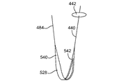
硬膜外針または硬膜外針の作業チャネルは、逆行防止装置またはバリアを挿入するための運搬手段、硬膜外腔内での軟組織の切除およびリモデリングを容易にする別の器具ともなる。バリアは、針もしくは作業管を通し、または内視鏡もしくは切開口を通して、硬膜外腔または神経孔内に、またはそれらに隣接して送入できる薄くて平らな装置である。このような逆行防止装置は、可撓性の、湾曲した、薄く平らな材料片から成る。このバリアは、削摩、切除、刺激、処置またはリモデリングの対象組織と、易損性神経および血管構造または硬膜外との間に配置されるために、組織の処置および切除中の損傷から神経および神経血管構造を保護する役割を果たす。組織を切除および削摩するための用具は易損性神経および血管構成物とは反対側で用いられ、構成物は不注意による損傷から安全に保護される。 The epidural needle or epidural needle working channel also serves as a vehicle for inserting a retrograde device or barrier, another instrument that facilitates resection and remodeling of soft tissue within the epidural space. A barrier is a thin, flat device that can be passed through a needle or working tube, or through an endoscope or incision, into or adjacent to the epidural space or nerve tunnel. Such a retrograde device consists of a flexible, curved, thin and flat piece of material. This barrier is placed between the target tissue to be abraded, resected, stimulated, treated or remodeled and from vulnerable nerves and vascular structures or epidural to prevent damage during tissue treatment and resection. It plays a role in protecting nerves and neurovascular structures. Tools for excising and ablating tissue are used on the opposite side of the vulnerable nerve and vascular components, and the components are safely protected from inadvertent damage.
アクセスするだけでなく、神経の保護および/または神経の位置決定、確立、除圧または選択的組織の除去もしくはリモデリングも行うことができる。組織除去装置は、組織除去面を伴ったまま、例えば、神経保護部材の中、それに沿って、その上を、またはそれを利用して、例えば神経保護部材のレールまたはチャネルによって、またはガイドワイヤに沿って所定位置内に前進させるか;あるいはガイドワイヤまたは神経保護部材等を用いて所定位置内に引き入れられる。組織除去面が適切に配置されると、組織除去面は、除去するために選択された侵害組織に接触する。 In addition to access, nerve protection and / or nerve localization, establishment, decompression, or selective tissue removal or remodeling can also be performed. The tissue removal device remains with the tissue removal surface, for example, in, along, on or using the neuroprotective member, for example, by a rail or channel of the neuroprotective member, or on a guide wire Or advanced into a predetermined position along; or withdrawn into a predetermined position using a guide wire or a nerve protection member or the like. When the tissue removal surface is properly positioned, the tissue removal surface contacts the infringing tissue selected for removal.
剥脱装置としては、例えば、剥脱、削除、および/または切断面を持った薄いベルトまたはリボンが挙げられ、神経孔を通して配置され、切除対象となる組織に対ししっかりと保持される。ベルトを保護シースまたはカバーの中に、少なくとも部分的に配置して、装置の剥脱面に対し曝される領域が、組織の剥脱および除去が望まれる領域にある程度限定されるようにすることもできる。剥脱部材は、平坦なものから曲がったものまで;狭いものから広いもの;または中実のものから中空のものまで、一または複数の、様々な潜在的に互換的な形状を取ることができる。剥脱面は様々な機能付与的な設計、または表面パターン、あるいは剥脱材料の粗さを持つこともできる。器具は、医師が作業できるように、剥脱部材の両自由端だけでなく、随意選択の保護スリーブまたはカバーの端部も患者の外に置かれる。 Exfoliation devices include, for example, thin belts or ribbons with exfoliation, deletion, and / or cutting surfaces that are placed through the nerve holes and held firmly against the tissue to be excised. The belt can also be placed at least partially within the protective sheath or cover so that the area exposed to the exfoliation surface of the device is limited to some extent to the area where tissue exfoliation and removal is desired. . The exfoliation member can take one or more of a variety of potentially compatible shapes, from flat to bent; narrow to wide; or solid to hollow. The exfoliation surface can have various functional designs, or surface patterns, or roughness of exfoliation material. The instrument is placed outside the patient not only on the free ends of the exfoliation member but also on the end of the optional protective sleeve or cover so that the physician can work.
選択的な保護スリーブまたはシースを具備するときは、スリーブの両端は患者の外側に引っ張り保持し、隣接する組織に有意な摩擦および/または損傷を与えることなくスリーブを通して剥脱ベルトまたはリボンを引き戻し、進められるようにする。まず、剥脱リボンの両端を同時に引っ張り、装置を後方および/または側方に引き、それによって脊椎組織をリボンの剥脱面および/または切断面に接触させる。リボンの一端を他端よりも強く引くと、リボンはより強く引かれた方向に動くと同時に、引く力が小さい反対側の力は維持されて、剥脱面と切除対象組織との間の運動に伴って摩擦を生じる。 When equipped with an optional protective sleeve or sheath, both ends of the sleeve are pulled out of the patient and the exfoliation belt or ribbon is pulled back and advanced through the sleeve without significant friction and / or damage to adjacent tissue. To be able to. First, pull both ends of the exfoliating ribbon simultaneously, pulling the device posteriorly and / or laterally, thereby bringing the spinal tissue into contact with the exfoliation and / or cutting surface of the ribbon. When one end of the ribbon is pulled harder than the other end, the ribbon moves in the stronger pulling direction, and at the same time, the force on the opposite side is kept small and the movement between the exfoliated surface and the tissue to be excised is maintained. Accompanied by friction.
開放式手術の実施例では、リボンもしくはベルト、および/またはカバーもしくはスリーブは、外科的切開を通して配置できる。経皮的実施例では、装置は、ワイヤにかぶせられた針を通して挿入できる。経皮的な方法と同様に、画像誘導法および/または硬膜内視鏡を利用して配置を補助することができる。 In an open surgical embodiment, the ribbon or belt and / or the cover or sleeve can be placed through a surgical incision. In the percutaneous embodiment, the device can be inserted through a needle over the wire. Similar to the percutaneous method, placement can be assisted using image guidance and / or dural endoscopes.
ひとたび外科的器具が設置されると、医師は剥脱によって、即ち切除対象組織を横切るように剥脱面を滑らせることによって、側窩および神経孔を拡張できる。剥脱の標的となる侵害組織としては、側黄色靱帯、前部および中央椎骨関節、および骨増殖体が挙げられるが、これらに限定されない。医師は、除去対象組織に対する剥脱面の力および速度を制御すると同時に、任意のカバーで剥脱部材にさらされる組織を画定する。 Once the surgical instrument is in place, the physician can dilate the fossa and nerve tunnel by exfoliation, i.e., by sliding the exfoliation surface across the tissue to be excised. Nociceptive tissues targeted for exfoliation include, but are not limited to, the lateral ligamentum flavum, the anterior and central vertebral joints, and bone proliferators. The physician defines the tissue that is exposed to the exfoliation member with an optional cover while simultaneously controlling the force and speed of the exfoliation surface against the tissue to be removed.
剥脱部材カバーの一つの実施例は、組織の剥脱を意図しない領域の剥脱面およびベルトもしくはリボンの裏側を包む。神経刺激装置を、剥脱面および/または保護カバーもしくはスリーブ内に組み入れ、設置が正確であることを確認し、医師が確実に神経組織を意図しない剥脱に供しないようにすることで、安全性を高めることもできる。 One example of an exfoliation member cover wraps the exfoliation surface in areas not intended for exfoliation of tissue and the back side of a belt or ribbon. Incorporate a nerve stimulator into the exfoliation surface and / or protective cover or sleeve to ensure correct installation and to ensure that the physician does not subject the nerve tissue to unintentional exfoliation. It can also be increased.
一つの実施例では、方法および器具は、外科的方法の後に圧迫包帯を置くことを含む。神経孔および側窩を拡張した後、外科的包帯としてベルト、またはリボンを剥脱した組織表面にしっかりと引いて当てて残すことは有用である。圧迫包帯は、神経孔をより広く開いた状態で止血を強化し、治癒を促進し、続く組織のリモデリングを促進することが期待される。さらには、外科的包帯は、神経または神経血管構造から組織の破壊物片を捕捉するバリアを提供すると同時に、手術部位に薬物を、おそらくはデポー剤として送入するための任意の技術も提供する。最後に、圧迫包帯は手術直後の間、神経根に向けて平滑面も提示するだろう。 In one embodiment, the method and instrument includes placing a compression bandage after the surgical method. After dilating the nerve holes and lateral fossa, it is useful to leave the belt or ribbon as a surgical bandage firmly pulled against the exfoliated tissue surface. Compression bandages are expected to enhance hemostasis, promote healing, and promote subsequent tissue remodeling with more wide open nerve openings. Furthermore, surgical bandages provide a barrier to capture tissue debris from nerves or neurovascular structures, while at the same time providing any technique for delivering drugs, possibly as a depot, to the surgical site. Finally, the compression bandage will also present a smooth surface towards the nerve root immediately after surgery.
本発明はまた、組織切除または剥脱後に、圧迫包帯として用いることができる方法および器具についても記載する。圧迫包帯の一つの実施例は、図49に描かれているように、神経孔を通して、椎骨関節および黄色靱帯の周囲がしっかりと包まれた位置に置かれる。治療組織表面にしっかり押しつけることによって、このような装置は所望組織のリモデリングを促進する;浮腫が、治癒初期に神経または血管組織を侵害して破壊片を含むのを予防し;手術後の止血を促進し;生組織表面と隣接する神経および血管構成物との間の瘢痕形成を阻止し;隣接する切除組織表面との接触に起因する、神経および血管構成物への炎症または刺激を避け;手術後の持続的薬物(例えばステロイド、凝血促進物、接着バリア)送入のためのメカニズムとして機能する。 The present invention also describes a method and instrument that can be used as a compression bandage after tissue resection or exfoliation. One example of a compression bandage is placed in a tightly wrapped position around the vertebral joint and the ligamentum flavum through the nerve hole, as depicted in FIG. By pressing firmly against the surface of the treated tissue, such a device promotes remodeling of the desired tissue; prevents edema from injuring nerve or vascular tissue and containing debris early in healing; postoperative hemostasis Preventing scar formation between the living tissue surface and adjacent nerve and vascular components; avoiding inflammation or irritation to nerve and vascular components due to contact with the adjacent resected tissue surface; Serves as a mechanism for the delivery of sustained drugs (eg, steroids, procoagulants, adhesion barriers) after surgery.
この神経孔圧迫包帯は、例えば任意の保護シースを含み、剥脱した面に対して経皮的にしっかりと固定させて保持してよい。代替的または任意で、組織剥脱後に別の経皮的に取り外せる圧迫包帯を、生分解性成分と共に、またはなしに設置できる。更に別の実施例では、完全な生分解性圧迫包帯は、圧迫包帯が作業後に完全に埋め込まれて残るようにして、剥脱した面に対してしっかりと置くことができる。 The nerve hole compression bandage may include, for example, an optional protective sheath, and may be held firmly and percutaneously fixed to the peeled surface. Alternatively or optionally, another percutaneously removable compression bandage after tissue exfoliation can be placed with or without the biodegradable component. In yet another embodiment, the complete biodegradable compression bandage can be placed securely against the exfoliated surface so that the compression bandage remains fully embedded after work.
選択的組織除去の間に、神経損傷のリスクを下げるために、本発明の実施例は、組織除去中に神経保護を供してもよい。一つの実施例では、神経保護部材、例えばシース、シールド、または逆行防止装置が、神経保護部材が神経孔内の侵害組織を、その下にある靭帯、隣接する神経根、脊髄神経節、およびまたは神経血管系から分離するように配置される(例えば、ガイドワイヤを用いて所定位置上に進める、または引き込む)。次に、組織除去装置を侵害組織と神経保護部材の間の位置に進めて、組織の除去を進める。神経保護部材は、非外傷性のプロフィルを好適に有し、組織損傷を減らす。例えば、部材は、丸みのついた縁部を具備できる。さらには、組織除去部材またはシールド上の低摩擦材料、コーティング、または親水性コーティングは、硬膜外腔および神経孔を通して、傷付けることなくこれらの装置を挿入することに役立つだろう。 To reduce the risk of nerve damage during selective tissue removal, embodiments of the present invention may provide neuroprotection during tissue removal. In one embodiment, a neuroprotective member, such as a sheath, shield, or anti-retroversion device, where the neuroprotective member removes the nociceptive tissue within the nerve tunnel, the underlying ligament, adjacent nerve root, spinal ganglion, and / or Positioned to separate from the neurovasculature (eg, advanced or retracted into position using a guide wire). Next, the tissue removal device is advanced to a position between the infringing tissue and the nerve protection member to proceed with tissue removal. The neuroprotective member preferably has an atraumatic profile and reduces tissue damage. For example, the member can comprise a rounded edge. Furthermore, low friction materials, coatings, or hydrophilic coatings on tissue removal members or shields may help insert these devices through the epidural space and nerve holes without injury.
神経保護部材は、患者組織に対し露出する組織除去装置を、開口部局所領域だけに制限する窓または局所開口部を含むことができる。開口部は、それが除去したい組織の領域の真下にくるように、例えば神経孔および侵害組織の真下に来るように配置できる。例えば、破壊片を除去するために、窓を通して洗浄および/または吸引を行うこともできる。窓を通して吸入を行い、侵害組織を嵌入し、かつ/または標的組織に密封を提供することもできる。任意で、シース窓は、組織除去装置と協働する切断部材を含んでもよい。さらに、組織除去装置は、その切断部材を窓に提供してもよい。窓は、医師によって、任意で、望むように開き、閉じ、または大きさを変更できる。例えば、窓は、送入中は閉じ、組織除去中は開き、そしてシース回復中は閉じることができる。神経保護部材が、裏面シールドを具える場合は、組織除去装置は、シールド縁部内、またはシールドと連結しているレールを通り送入できる。 The neuroprotective member can include a window or local opening that limits the tissue removal device exposed to the patient tissue to only the opening local area. The opening can be positioned so that it is directly below the area of tissue that it wants to remove, for example, directly below the nerve holes and nociceptive tissue. For example, cleaning and / or aspiration can be performed through the window to remove debris. Inhalation can also be performed through the window to insert the infringing tissue and / or provide a seal to the target tissue. Optionally, the sheath window may include a cutting member that cooperates with the tissue removal device. Further, the tissue removal device may provide the cutting member to the window. The window can optionally be opened, closed, or resized as desired by the physician. For example, the window can be closed during delivery, open during tissue removal, and closed during sheath recovery. If the neuroprotective member comprises a back shield, the tissue removal device can be fed into the shield edge or through the rail connected to the shield.
神経保護は、組織除去中に提供でき、例えば選択的組織除去中の神経学的損傷のリスクを下げることができる。神経保護部材は、針先端を神経孔に隣接させて、またはその中に置いた後に配置できる。神経保護部材は、シース、シールド、逆行防止装置、またはこれらの組合せでよい。 Neuroprotection can be provided during tissue removal, for example, reducing the risk of neurological damage during selective tissue removal. The neuroprotective member can be placed after placing the needle tip adjacent to or in the nerve hole. The neuroprotective member may be a sheath, a shield, a retrograde prevention device, or a combination thereof.
追加の安全予防装置として、本発明の実施例は、任意で神経位置決定部材を含み、神経保護部材および/または組織除去装置を、確実に、適切な場所に配置できるようにする。神経位置決定部材は、神経保護部材および/または組織除去装置とは別の部材でも、それらと一体化してもよい。一つの実施例では、神経保護部材は、一体化された神経位置決定部材を持つシースを含む。別の実施例では、神経保護部材は、一体化された神経位置決定部材を持つシールドを含む。さらに別の実施例では、神経保護部材は、組織除去中に静止状態を保つための、運動中の組織除去部材に隣接して置かれる組織除去器具の一部分を含んでよい。伝導性の神経位置決定部材を用いて、神経構造およびそれらに隣接する血管構造が、非作業域にまたは神経保護部材の裏側に在ることを確認することができる。 As an additional safety prevention device, embodiments of the present invention optionally include a nerve locating member to ensure that the neuroprotective member and / or tissue removal device can be placed in place. The nerve locating member may be a member separate from or integrated with the nerve protection member and / or the tissue removal device. In one embodiment, the neuroprotective member includes a sheath having an integrated nerve locating member. In another embodiment, the neuroprotective member includes a shield with an integrated nerve locating member. In yet another example, the neuroprotective member may include a portion of a tissue removal instrument that is placed adjacent to the moving tissue removal member to remain stationary during tissue removal. A conductive nerve locating member can be used to confirm that the nerve structures and the vascular structures adjacent to them are in the non-working area or on the back side of the nerve protection member.
神経保護部材の裏面にある神経位置決定部材は(即ち適切に配置された時には、神経根と接触するか、それに隣接する神経位置推定部材の側)を、刺激波形を用いて活性化して神経根を刺激し、それによって裏面が神経根に近接して配置されていることを確認する積極的な制御を提供できる。適切な低強度の電気刺激を裏面表面に加えると、患者の四肢の感覚および/または運動神経が刺激される。同様に、神経保護部材の作業側または組織除去部材上(即ち神経保護部材、または除去対象に選ばれた侵害組織に面する組織除去部材の側)にある神経位置決定部材を、負の反応または神経刺激なしであることを予想しながら刺激波形を用いて作動させ、作業側が神経根に接触していないこと、および組織除去を安全に進めることができることを確認する。神経位置決定部材は、神経保護部材および/または組織除去部材の任意の側または表面に具備できる。 The nerve positioning member on the back surface of the nerve protection member is activated by using the stimulation waveform to activate the nerve root (that is, the side of the nerve position estimation member that is in contact with or adjacent to the nerve root when properly placed). Can be positively controlled, thereby providing positive control to ensure that the back surface is positioned close to the nerve root. Appropriate low intensity electrical stimulation applied to the back surface stimulates the sensation and / or motor nerves of the patient's limbs. Similarly, the nerve locating member on the working side of the neuroprotective member or on the tissue removal member (i.e., the side of the tissue removal member facing the injured tissue selected for removal) or negative response or Operate with a stimulus waveform, expecting no nerve stimulation, and verify that the working side is not in contact with the nerve root and that tissue removal can proceed safely. The nerve localization member can be provided on any side or surface of the nerve protection member and / or the tissue removal member.
これらの方法および装置を用いた安全な組織の除去、削摩およびリモデリングは、正確な神経位置決定を補助する補完的方法および器具によってさらに可能になる。神経位置決定は、キャップをされた硬膜外針先端内;変更対象組織と接触する硬膜外用具内;または作業バリアの一側または両側に配置された伝導性材料を通して神経を刺激することによって実施される。神経刺激は、電気刺激に対する感覚および/または運動性の反応について、患者をモニタリングすることと関連して行われるだろう。 Safe tissue removal, ablation and remodeling using these methods and devices is further enabled by complementary methods and instruments that assist in accurate nerve localization. Nerve positioning is accomplished by stimulating the nerve through a capped epidural needle tip; in an epidural device that contacts the tissue to be modified; or through a conductive material placed on one or both sides of the working barrier. To be implemented. Neural stimulation may be performed in conjunction with monitoring the patient for sensory and / or motor responses to electrical stimulation.
前記逆行防止装置もまた、作業側および/非作業側に、伝導性部材を包含する神経位置決定能力を含むことができる。伝導性部材を用いて、神経およびそれらに隣接する血管構成物がバリアの非作業側に在ることを証明できる。バリアを側窩または神経孔を通して設置すると、非作業域表面への適切な、低強度の電気刺激は患者の四肢の感覚および運動神経を刺激するが、一方作業表面では、適切な電気伝導性により神経刺激は起きない。 The anti-reverse device can also include a nerve localization capability that includes a conductive member on the working side and / or the non-working side. Conductive members can be used to prove that nerves and vascular components adjacent to them are on the non-working side of the barrier. When the barrier is placed through a foveal or nerve hole, appropriate low-intensity electrical stimulation to the non-working area surface stimulates the sensation and motor nerves of the patient's limbs, while at the working surface, due to proper electrical conductivity Nerve stimulation does not occur.
神経刺激は、体感覚性誘発電位(SSEP)、運動誘発電位(MEP)をモニタリングすること、および/または四肢の筋収縮の視覚的兆候を探すことによって、モニタリングできる。(体感覚性誘発電位(SSEP)は、感覚神経、または混合感覚運動神経を、繰り返し、準最大に電気的刺激することで非侵襲性に試験できる。脳は神経刺激に反応して脳活動電位(電気波)を発するが、これは、表面電極を用いて頭蓋および脊椎全体について測定および記録することができる。典型的には、必要とされる電流が小さく、アーチファクトが低いことから、術中SSEPモニタリングには針電極が用いられる。記録された反応は、神経構造の活性化を表す一連の波である。)SSEP、SEP、MEP、またはEMGのフィードバックは、視覚的にモニタリングおよび/または記録することができ、あるいは聴覚的にモニタリングでき、聴覚信号の大きさまたは周波数に関係する定量的なフィードバック(例えば、ガイガーカウンタタイプの定量的聴覚フィードバック)に変換できる可能性もある。信号または刺激の強度をモニタリングし、これを用いて設置時の神経の位置を決定することもできる。 Neural stimulation can be monitored by monitoring somatosensory evoked potentials (SSEP), motor evoked potentials (MEP), and / or looking for visual signs of limb muscle contraction. (Somatosensory evoked potentials (SSEPs) can be tested non-invasively by repeatedly stimulating sensory nerves or mixed sensorimotor nerves to submaximal electrical stimulation. (Electrical waves), which can be measured and recorded for the entire skull and spine using surface electrodes, typically because of the small current required and low artifacts, so intraoperative SSEP Needle electrodes are used for monitoring, and the recorded response is a series of waves representing activation of the neural structure.) SSEP, SEP, MEP, or EMG feedback is visually monitored and / or recorded Can be audibly monitored or quantitative feedback related to the magnitude or frequency of the auditory signal (eg, Geigerka There is a possibility that can be converted into quantitative auditory feedback) of Ntataipu. The intensity of the signal or stimulus can be monitored and used to determine the location of the nerve at placement.
例えば、外科医は神経刺激装置を用いて、バリアの作業側の易損性神経が刺激されていないことを、作業用具を用いた組織処理を開始するまえに確認することができる。例えば、側窩または神経孔内にバリアを配置すると、外科医は最初にバリアの作業側に沿って、次にバリアの裏面に沿って電流を送ることができる。作業側の低レベルの刺激は、神経を刺激しないと予想されるが、一方バリア裏面への同じ刺激は背根、神経根、または神経節を刺激すると予想される。 For example, the surgeon can use a nerve stimulator to confirm that the vulnerable nerves on the working side of the barrier are not stimulated before starting tissue processing with the work implement. For example, when a barrier is placed in a fovea or nerve hole, the surgeon can send current first along the working side of the barrier and then along the back side of the barrier. A low level of stimulation on the working side is expected not to stimulate the nerve, while the same stimulation on the backside of the barrier is expected to stimulate the dorsal root, nerve root, or ganglion.
神経位置決定は、外科的機器(例えば焼灼装置、把握器、カミソリ、バー、プローブ等)を追加することによって、さらに可能にできる。電流を選択的に送りながら、患者を神経刺激についてモニタリングし、電流を選択的に送りながら(例えば電気的に刺激しながら)同時に患者を同様の電気刺激についてモニタリングして、例えば神経の位置をさらに決定するといった神経位置のさらなる決定を可能にする外科的機器を用いることができる。刺激を定量化することで、神経の位置を決定することが可能になる。例えば、使用者は、装置が神経構成物に接近するより強い刺激を感知し、または神経構成物に接近し、または遠ざかる刺激体を区別できるように較正されたセンサ入力を用いることができる。安全性を高めるために、外科装置は、組織除去前または除去(例えば切除)中に自動的に刺激を加えるように設計でき、かつ神経刺激が感知された時には組織除去(例えば切除)を自動的に停止するように設計できる。 Nerve localization can be further enabled by adding surgical instruments (eg, cautery devices, graspers, razors, bars, probes, etc.). While selectively sending current, the patient is monitored for neural stimulation, while selectively sending current (eg, electrically stimulated) and simultaneously monitoring the patient for similar electrical stimuli, for example, to further determine the location of the nerve Surgical instruments that allow further determination of the nerve location, such as determining, can be used. By quantifying the stimulus, it is possible to determine the position of the nerve. For example, the user can use sensor inputs that are calibrated so that the device can sense stronger stimuli as they approach the neural component, or distinguish stimuli that approach or move away from the neural component. To increase safety, the surgical device can be designed to automatically stimulate before or during tissue removal (eg, ablation) and automatically remove tissue (eg, ablation) when nerve stimulation is sensed. Can be designed to stop at any time.
組織除去装置(例えば組織剥脱装置)は、経皮的、または開放手術のいずれかによって、脊椎の神経孔を通り、かつ少なくとも一部が椎間関節の前方境界の周囲、黄色靱帯の後方に位置するように配置できる。代替的または任意で、除去装置(例えば剥脱装置)を、椎間関節前方の神経孔を通して黄色靱帯そのものの中に、もしくは貫通させ、またはその後方に配置することができる。脊椎神経孔に配置した後、装置を用いて椎間関節の前方、側窩および神経孔内の神経血管構成物を侵害している組織を除去または選択的に除去し、選択的な組織の除去によって側窩および神経孔を拡張することができる。除去対象となる侵害組織としては、黄色靱帯、前方および中央椎間嚢、椎間骨棘、および/または骨増殖体が挙げられるが、これらに限定されない。別の実施例では、組織除去装置は、中央狭窄を除去するために配置できる。 A tissue removal device (eg, a tissue exfoliation device) is placed either through the perforation of the spine and at least partially around the anterior boundary of the facet joint, behind the ligamentum flavum, either percutaneously or by open surgery. Can be arranged. Alternatively or optionally, an ablation device (eg, an exfoliation device) can be placed through, or penetrate, the ligamentum flavum itself through the anterior ostium of the facet joint. After placement in the spinal nerve foramen, the device is used to remove or selectively remove tissue that is invading the anterior face of the facet joint, the fovea and the neurovascular components in the nerve hole, and selective tissue removal Can expand the fovea and nerve holes. Nociceptive tissue to be removed includes, but is not limited to, the ligamentum flavum, anterior and central discs, intervertebral spines, and / or bone growths. In another example, the tissue removal device can be positioned to remove the central stenosis.
組織除去装置の組織除去面は、侵害組織の全て、または一部を選択的に除去するための各種組織除去部材を含むことができる。一つの実施例では、組織除去面は、一つまたは複数の、例えば緊張した状態で、侵害組織を横切って牽引または引っ張られ、切断、削除等によって組織を除去する、非動力式の組織除去機械部材を含む。 The tissue removal surface of the tissue removal device can include various tissue removal members for selectively removing all or part of the infringing tissue. In one embodiment, the tissue removal surface is one or more non-powered tissue removal machines that are pulled or pulled across the infringing tissue, eg, in tension, to remove the tissue by cutting, deleting, etc. Includes members.
組織除去中、組織除去装置は侵害組織を横切って、単一方向に牽引しても、または交互に牽引してもよい。機械部材は、ブレード、帯鋸、または糸鋸のような切断部材を含むことができる。ブレードは、所望の様々な形(例えば鋸歯型)、サイズ、および構成を含んでよい。代替的に、機械部材は、ダイヤモンドまたは酸化物コーティングのような研磨剤を含んでよい。さらには、協働するブレードを具備させ、ギロチン型またはハサミ型の切断動作を得ることができる。ブレードは、組織除去装置に取り付けることができ、または押抜き、破砕、または型押しし、その後、任意で装置を用いて押抜きした縁部を研削して作ることができる。代替的に、ブレードは化学的エッチング工程によっても形作ることができる。ブレードは切断を容易にする3次元プロフィルを含み、例えば弓形または波形、または「チーズおろし」プロフィルを含むことができる。さらには、ブレードは、組織を除去する方向に対し、一または複数の角度で設置できる。ブレードの切断面は、単一方向に向けることも、複数の方向に向けることもできる。これに加えて、ブレードは鋸歯型にできる。別の代替物としては、機械部材は、切断ワイヤまたは糸鋸、例えば一または複数のギグリー鋸を含むことができる。複数または切断ワイヤもしくはギグリー鋸を一つに連結または組立てるか、あるいは平坦にして実質的に平らな切断面を形作ることができる。さらには、糸鋸またはギグリー鋸には、リボンの裏張りが取り付けられ、前記リボンは組織切除装置の貫通深度を制限する(「深さ止めリボン」)。 During tissue removal, the tissue removal device may be pulled unidirectionally or alternately across the infringing tissue. The mechanical member can include a cutting member such as a blade, band saw, or yarn saw. The blade may include various desired shapes (eg, sawtooth), sizes, and configurations. Alternatively, the mechanical member may include an abrasive such as a diamond or oxide coating. Furthermore, a cooperating blade can be provided to obtain a guillotine-type or scissors-type cutting operation. The blade can be attached to a tissue removal device, or can be made by punching, crushing, or embossing, and optionally grinding the punched edges using the device. Alternatively, the blade can also be shaped by a chemical etching process. The blade includes a three-dimensional profile that facilitates cutting, and may include, for example, an arcuate or corrugated, or “cheese grated” profile. Furthermore, the blade can be placed at one or more angles to the direction of tissue removal. The cutting surface of the blade can be oriented in a single direction or in multiple directions. In addition, the blade can be serrated. As another alternative, the mechanical member can include a cutting wire or a yarn saw, such as one or more Gigly saws. Multiple or cutting wires or Gigly saws can be connected or assembled together or flattened to form a substantially flat cutting surface. In addition, the yarn or Gigly saw is fitted with a ribbon backing that limits the penetration depth of the tissue excision device ("depth stop ribbon").
別の実施例では、組織除去面は、一または複数の動力式の組織除去機械部材を含む。動力式組織除去機械部材は、例えば、帯鋸、ベルトシェーバ、回転式バー、またはブレード、レシプロ式バーまたはブレード等を含むことができる。 In another embodiment, the tissue removal surface includes one or more powered tissue removal machine members. The powered tissue removal machine member can include, for example, a band saw, belt shaver, rotating bar, or blade, reciprocating bar or blade, and the like.
組織除去面は、組織の削摩、気化、破壊、またはモジュラスを変更する、例えば組織除去を支援する、エネルギー送入システムを有することができる。組織除去システムは、一または複数種類のエネルギーを送入して組織の除去を促進できる。エネルギーは、電気、超音波、熱、マイクロ波、レーザ、冷気、またはこれらの組合せでよい。別の実施例では、組織除去面は、一または複数の、組織除去/削摩のための電気外科手術部材を含む。付加的または代替的に、電気外科手術部材は、止血を達成し、かつ/または神経位置決定を促進するのにも利用できる。単極または双極性のRF部材は、例えば、熱波または実質的な非熱波を用いて、利用および実現できる。 The tissue removal surface may have an energy delivery system that alters tissue ablation, vaporization, destruction, or modulus, eg, assists in tissue removal. The tissue removal system can deliver one or more types of energy to facilitate tissue removal. The energy can be electricity, ultrasound, heat, microwave, laser, cold, or a combination thereof. In another embodiment, the tissue removal surface includes one or more electrosurgical members for tissue removal / abrasion. Additionally or alternatively, the electrosurgical member can be utilized to achieve hemostasis and / or facilitate nerve localization. Monopolar or bipolar RF members can be utilized and implemented using, for example, thermal waves or substantially non-thermal waves.
その他の公知組織除去部材を、たとえばレーザ、高圧流体、熱部材、放射性部材等を含む組織除去装置とともに利用してもよい。各種組織除去部材は、所要であれば、様々な組み合わせで用いることができると理解すべきである。 Other known tissue removal members may be utilized with tissue removal devices including, for example, lasers, high pressure fluids, thermal members, radioactive members, and the like. It should be understood that the various tissue removal members can be used in various combinations if desired.
設置、診断、治療、および/または除去中の摩擦を減らすために、アクセス部材、神経保護部材、および/または組織除去装置は、潤滑性コーティング、例えば親水性コーティング、ポリ(テトラフルオロエチレン)コーティング等を有するか、または含むことができる。コーティングは、設置、診断、治療、および/または除去中の摩擦を減らすことができる。さらには、組織除去装置、アクセス部材、および/または神経保護部材は、生体適合性および/または非脆弱性でよい。破砕片除去部材が提供されてもよい。 To reduce friction during installation, diagnosis, treatment, and / or removal, the access member, neuroprotective member, and / or tissue removal device can be lubricated, eg, hydrophilic coating, poly (tetrafluoroethylene) coating, etc. Can be included or included. The coating can reduce friction during installation, diagnosis, treatment, and / or removal. Further, the tissue removal device, access member, and / or neuroprotective member may be biocompatible and / or non-fragile. A fragment removal member may be provided.
方法は、硬膜外腔内に挿入された硬膜針を通して行うことができる。硬膜外針は、経皮的、または開口切開により、または標準的な後部正中傍(層間)または正中線(棘突間)法を利用して、当技術分野の通常の技術レベルを有する者に公知である抵抗消失技術を用いて、挿入することができる。 The method can be performed through a dural needle inserted into the epidural space. Epidural needles are those with ordinary skill in the art, percutaneously or by open incision or using standard posterior midline (interlayer) or midline (interspinous) methods Can be inserted using a known resistance disappearance technique.
次に、カテーテルを針に通して硬膜外腔内に入れることができる。カテーテルの遠位先端部には、例えば、針先端を覆うように設計できる保護フード、カバー、または針キャップを備えることができる。カテーテル遠位先端を硬膜外腔内に配置すると、使用者は保護フードカバーを開くことができる。保護カバーを開いた後、保護フードカバーが硬膜針先端領域内にある鋭利縁部または尖頭をしっかり封じ込めるまで、カテーテルを針の中に滑らせ収納できる。保護フードカバーが針先端をしっかり保護している時、カテーテルを針に固定できる。針先端に保護フードカバーが付いた針は、針先の鈍い機器として配列することができる。 The catheter can then be passed through the needle and into the epidural space. The distal tip of the catheter can be provided with a protective hood, cover, or needle cap that can be designed to cover the needle tip, for example. When the catheter distal tip is placed in the epidural space, the user can open the protective hood cover. After opening the protective cover, the catheter can be slid into the needle and stored until the protective hood cover securely encloses the sharp edge or tip within the dural needle tip region. When the protective hood cover securely protects the needle tip, the catheter can be secured to the needle. A needle with a protective hood cover at the tip of the needle can be arranged as a dull instrument.
次に針は、針の遠位端が神経孔に隣接する側窩内に入るまで進めることができる。使用者は、針からのフィードバックの触覚、画像誘導法(例えばX線透視検査)、またはこれらの組合せを利用して、針遠位端を側窩に配置することができる。 The needle can then be advanced until the distal end of the needle enters the lateral fovea adjacent to the nerve hole. The user can place the needle distal end in the fovea using tactile feedback feedback from the needle, image guidance (eg, fluoroscopy), or a combination thereof.
組織除去装置は、除去対象の侵害組織と神経保護部材の間に配置できる。湾曲した可撓性のスタイレットをカテーテル内に挿入できる。次に、カテーテルを、針の中を前進させることができる。カテーテルの先端を、例えば椎骨関節の下位境界線に沿って、神経および神経血管構成物に向けて、神経孔を通し横に動かすことができる。 The tissue removal device can be disposed between the infringing tissue to be removed and the nerve protection member. A curved flexible stylet can be inserted into the catheter. The catheter can then be advanced through the needle. The tip of the catheter can be moved laterally through the nerve hole, for example along the lower boundary of the vertebral joint, towards the nerve and neurovascular components.
非外傷性の湾曲した針を硬膜外カテーテルの中を進めて、神経孔、さらには切除対象の組織と保護された神経組織の間を通して動かすことができる。 An atraumatic curved needle can be advanced through the epidural catheter and moved through the nerve hole and even between the tissue to be excised and the protected nerve tissue.
硬膜外針の中を湾曲した薄いシールドを前進させて、神経孔を通して動かすことができ、さらには切除対象の組織と保護された神経組織の間に配置することもできる。 A curved thin shield can be advanced through the epidural needle and moved through the nerve hole, and can also be placed between the tissue to be excised and the protected nerve tissue.
カテーテル、湾曲した針、またはシールドは、例えば除去対象の組織と神経および神経血管構成物との間のバリアとして利用できる。カテーテル、湾曲した針、またはシールドは、例えば除去対象の組織と神経および神経血管構成物との間へのバリアの送入を補助できる。カテーテル、湾曲した針、またはシールドは、神経孔内で拡張して、例えば除去対象の組織と神経および神経血管構造物との間のバリアとして利用することができる。神経保護部材は、非外傷性のプロフィルを有し、例えば組織への損傷を減らすことができる。神経保護部材は、丸みのついた縁部を有することができる。 A catheter, curved needle, or shield can be used, for example, as a barrier between the tissue to be removed and the nerve and neurovascular components. A catheter, curved needle, or shield can assist in delivering the barrier between the tissue to be removed and the nerve and neurovascular components, for example. A catheter, curved needle, or shield can be expanded within the nerve hole and utilized, for example, as a barrier between the tissue to be removed and the nerve and neurovascular structures. The neuroprotective member has an atraumatic profile and can reduce, for example, tissue damage. The neuroprotective member can have a rounded edge.
使用者は、例えば、遠位の透明な先端で覆うことができる光ファイバ部材を用いて、硬膜外腔を見ることができる。光ファイバ部材は、硬膜カテーテル内を送入できる。光ファイバ部材は、硬膜針の中または隣接する作業チャネルを用いて送入できる。 The user can view the epidural space using, for example, an optical fiber member that can be covered with a distal transparent tip. The optical fiber member can be fed through the dural catheter. The fiber optic member can be delivered using a working channel in or adjacent to the dural needle.
開放式手術の実施例では、アクセスは、カニューレ式のボールチッププローブのようなカニューレ式プローブ、Woodsonエレベータ、またはホッケースティックハイブリッド(Hockey Stick hybrid)を含むアクセス部材を用いて実現できる。プローブは、外科的切開を通し、硬膜外腔内に配置できる。非外傷性針のような湾曲部材を、次にプローブのカニューレの中を前進させて、横方向に動かし、神経孔にカニューレ挿入することができる。直接目で見ること、および触覚のフィードバックに加え、開放式のアクセスは、画像誘導法、硬膜外内視鏡、またはその他の視覚化技術を用いて補助することができる。 In open surgical embodiments, access can be achieved using an access member that includes a cannulated probe, such as a cannulated ball tip probe, a Woodson elevator, or a Hockey Stick hybrid. The probe can be placed through the surgical incision and into the epidural space. A curved member, such as an atraumatic needle, can then be advanced through the probe cannula, moved laterally, and cannulated into the nerve hole. In addition to direct visual and tactile feedback, open access can be assisted using image guidance, epidural endoscopes, or other visualization techniques.
神経保護部材がシースを含むときは、組織除去装置は、シースの中またはシースに沿って、またはシースと共に送入できる。シースは、窓または局所開口部を有することができ、これらは患者組織への組織除去装置の露出を開口部の局所領域にだけ限定している。開口部は、除去を所望する組織の領域の真下、例えば神経孔および中心管、側窩の中、および/または神経孔内の侵害組織の真下に配置できる。 When the neuroprotective member includes a sheath, the tissue removal device can be delivered in or along the sheath or with the sheath. The sheath may have a window or local opening, which limits the exposure of the tissue removal device to patient tissue only to the local area of the opening. The opening can be placed directly under the region of tissue that is desired to be removed, eg, in the nerve tunnel and central canal, lateral fossa, and / or directly under the nociceptive tissue within the nerve hole.
窓を通して、例えば破砕片を除去するために、洗浄および/または吸引を行うことができる。窓を通して吸入し、侵害組織を嵌合し、および/または標的組織に対し密封を供し、および/または組織破砕片を取り除き、および/または流体を取り除くことができる。シースの窓は、組織除去装置と協働する切断または削摩部材を有することができる。組織除去装置は、窓に組織除去部材を提供することができる。所要であれば、窓は任意で、医師によって開放、閉鎖、または大きさの変更ができる。例えば、窓は、送入中は閉鎖し、組織除去中は開放し、次にシース格納中は閉鎖することができる。 Washing and / or aspiration can be performed through the window, for example to remove debris. It can be inhaled through the window, fitted with infringing tissue, and / or provided a seal against the target tissue, and / or tissue debris removed and / or fluid removed. The sheath window may have a cutting or ablation member that cooperates with the tissue removal device. The tissue removal device can provide a tissue removal member in the window. If desired, the window is optional and can be opened, closed, or resized by the physician. For example, the window can be closed during delivery, open during tissue removal, and then closed during sheath storage.
神経位置決定部材を用い、神経保護部材および/または組織除去装置の位置決定を向上させることができる。神経位置決定部材は分離部材を有することができるか、または神経保護部材および/または組織除去装置と一体化できる。一つの実施例では、神経保護部材は、神経位置決定部材が一体化されたシースまたはその他部材を有することができる。伝導性神経位置決定部材を用いて、神経構成物が非作業域またはバリアの裏側にあることを確認できる。神経保護部材裏側(即ち、適切に配置された時に神経根と接触する神経保護部材の側)の神経位置決定部材は、裏側の電流(例えば波形として送られる)によって作動させることができる。裏側電流は、神経根または他の神経構成物を刺激することができ、例えば神経根に隣接して裏側が位置取りされている使用者に信号を送ることができる。裏側表面の低強度電流は、患者の四肢の感覚または運動神経を刺激できる。神経保護部材の作業側(即ち除去対象の侵害組織に対向する神経保護部材の側)にある神経位置決定部材は、正面側の電流(例えば波形、例えば裏側の電流の波形とは異なる特徴を持った波形として送られる)によって作動できる。電流は負の反応を刺激できるか、または全く神経を刺激せず、例えば作業側が神経根と接触していないか、組織が安全に除去できている使用者に信号を送ることができる。神経位置決定部材は、神経保護部材の任意の側、または全ての側に提供することができる。 A nerve localization member can be used to improve the localization of the nerve protection member and / or the tissue removal device. The nerve locating member can have a separating member or can be integrated with the neuroprotective member and / or the tissue removal device. In one embodiment, the neuroprotective member may have a sheath or other member with an integrated nerve locating member. A conductive nerve locating member can be used to confirm that the nerve component is behind the non-working area or barrier. The nerve positioning member on the back side of the nerve protection member (ie, the side of the nerve protection member that contacts the nerve root when properly placed) can be actuated by a current on the back side (eg, sent as a waveform). The backside current can stimulate nerve roots or other neural components, for example, can signal a user whose backside is located adjacent to the nerve root. The low intensity current on the back surface can stimulate the sensation or motor nerve of the patient's limb. The nerve locating member on the working side of the nerve protection member (that is, the side of the nerve protection member facing the infringing tissue to be removed) has characteristics different from the current on the front side (for example, the waveform of the current on the back side, for example, the waveform of the current on the back side). Sent as a waveform). The current can stimulate a negative response or not stimulate the nerve at all, for example, to signal a user whose working side is not in contact with the nerve root or where the tissue can be safely removed. The nerve locating member can be provided on any or all sides of the neuroprotective member.
任意で神経保護および/または神経位置決定を含めてアクセスを確立させ、組織除去装置を、組織除去面が除去対象となる侵害組織に接触するように配置して、使用者は組織を選択的に除去できる。組織の除去は、神経および/または神経血管を除圧するだろう。侵害組織の弾性モジュラスを変更して、例えば、組織の除去を促進できる。例えば、軟組織のモジュラスを上げて、軟組織に組織除去部材の手がかりを得ることができる。このようなモジュラスの変更は、例えば圧迫、変性、電気手術提示、熱リモデリング(高温または低温)、化学的変化、エポキシもしくはグルー、またはヒドロゲル、あるいはこれらの組合せによって実現できる。モジュラス変更中または変更後の組織のリモデリングは侵害を軽減し、組織除去の必要性を回避または減ずることができる。 Access is optionally established, including neuroprotection and / or nerve localization, and the tissue removal device is positioned so that the tissue removal surface contacts the infringing tissue to be removed, and the user selectively selects the tissue. Can be removed. Removal of the tissue will decompress the nerve and / or neurovascular. The elastic modulus of the infringing tissue can be changed, for example, to facilitate tissue removal. For example, the modulus of the soft tissue can be increased to obtain a clue to the tissue removal member in the soft tissue. Such a change in modulus can be achieved, for example, by compression, denaturation, electrosurgical presentation, thermal remodeling (high or low temperature), chemical change, epoxy or glue, or hydrogel, or combinations thereof. Tissue remodeling during or after the modulus change can reduce infringement and avoid or reduce the need for tissue removal.
エネルギー送入システムと組み合わせるか、または単独で、組織除去手段である、一つまたは複数の非動力式の組織除去機械部材(例えばブレードまたは鋸のような剥脱または切断部材)を、侵害組織を横断するように引いて、切断、削除、薄切、はさみ切り、断裁、破砕、剪断、剥脱、またはこれらの組合せによって組織を除去できる。ブレードは、侵害組織を、一方向に横断して引くこと、および/または前後に引くことができる。組織除去機械部材は、ダイヤモンドまたは酸化コーティング剤のような研磨剤を有してよい。 Crossing the infringing tissue with one or more non-powered tissue removal mechanical members (eg, exfoliating or cutting members such as blades or saws) that are combined with the energy delivery system or alone, the tissue removal means The tissue can be removed by cutting, deleting, slicing, scissor cutting, cutting, crushing, shearing, exfoliation, or a combination thereof. The blade can pull the infringing tissue across in one direction and / or back and forth. The tissue removal mechanical member may have an abrasive such as diamond or an oxidative coating.
ブレードは、様々な形状、サイズおよび構成を有することができる。ブレードは、例えばギロチン型またはハサミ型の切断動作で協働できる。ブレードは、組織除去装置に取り付けるか、または一体化できる。ブレードは、組織除去装置によって研削、押抜き、または型押しによって形成することができる。ブレードは、組織除去装置の押抜き、または型押しされた縁部を研削することによって形成することができる。ブレードは、化学的エッチング工程によって形作ることができる。ブレードは切断を容易にする3次元プロフィルを有し、例えば弓形または波形、または「チーズおろし」プロフィルを持つことができる。ブレードは、組織を除去する方向に対し、一または複数の角度で設置できる。ブレードは、組織を横断して切断するブレード(即ち帯鋸のような)を用いて作ることができる。ブレードは切断面を持つことができる。切断面は、一方向または複数の方向に向けることができる。ブレードは鋸歯とすることが可能である。 The blade can have various shapes, sizes and configurations. The blades can cooperate in a guillotine-type or scissor-type cutting action, for example. The blade can be attached to or integrated with the tissue removal device. The blade can be formed by grinding, punching or stamping with a tissue removal device. The blade can be formed by grinding a punched or embossed edge of a tissue removal device. The blade can be shaped by a chemical etching process. The blade has a three-dimensional profile that facilitates cutting, for example, it can have an arcuate or corrugated, or “cheese grated” profile. The blade can be placed at one or more angles to the direction of tissue removal. The blade can be made using a blade that cuts across the tissue (ie, like a band saw). The blade can have a cutting surface. The cutting plane can be oriented in one direction or multiple directions. The blade can be a saw blade.
鋸は、糸鋸または鋸でよい。糸鋸はギグリー鋸でよい。複数の糸鋸またはギグリー鋸を一つに連結または組み立てることができ、または平板にして実質的に平坦な切断面を形作ることができる。糸鋸は、平らなリボンの上に装着できる。リボンは、例えば鋸の貫通を制限する深止め装置でよい。 The saw may be a yarn saw or a saw. The thread saw can be a Gigly saw. Multiple yarn saws or Gigly saws can be connected or assembled together, or can be flattened to form a substantially flat cut surface. The yarn saw can be mounted on a flat ribbon. The ribbon may be, for example, a deep stop device that limits saw penetration.
組織除去面は、一または複数の動力式の組織除去機械部材を有することができる。動力式組織除去機械部材は、例えば帯鋸、ベルトシェーバ、回転バーまたはブレード、レシプロ式バーまたはブレード、あるいはこれらの組合せでよい。 The tissue removal surface can have one or more powered tissue removal machine members. The powered tissue removal machine member may be, for example, a band saw, a belt shaver, a rotating bar or blade, a reciprocating bar or blade, or a combination thereof.
当該器具および方法により、病的な脊椎組織の選択的除去を容易にして、脊椎狭窄を煩う患者の症状緩和を可能にする。 The instruments and methods facilitate selective removal of pathological spinal tissue and allow relief of patients suffering from spinal stenosis.
脊椎の解剖を変更するための方法を開示する。この方法は、手術器具を硬膜外腔に送ること、および脊椎の側窩、神経孔または中心管内の神経または血管構成物を侵害している組織を、器具を使って手術的に変更することを含む。組織の外科的な変更は、組織を削摩すること、組織を切除すること、組織を除去すること、組織を剥脱すること、組織を収縮させること、組織にステント移植すること、組織を保持すること、または組織を熱縮小させることを包含する。外科的な組織の変更は、これに加えて、脊椎の側窩、神経孔、または中心管を拡張することも含む。 A method for altering spinal anatomy is disclosed. This method involves sending a surgical instrument to the epidural space and surgically altering tissue invading nerves or vascular components in the lateral fovea, nerve hole or central canal of the spine using the instrument including. Surgical changes in tissue include ablating tissue, excising tissue, removing tissue, exfoliating tissue, shrinking tissue, stenting tissue, retaining tissue Or heat shrinking the tissue. Surgical tissue alterations additionally include dilating the spinal fossa, nerve hole, or central canal.
手術器具を硬膜外腔に送入することは、硬膜外針を硬膜腔に送入することを含み、脊椎の側窩、神経孔または中心管を拡張することは、硬膜外針を通して送入された用具を用いて、焦点をあてた組織の変更を含むことができる。また、手術器具の硬膜外腔への送入は、硬膜外針を硬膜外腔に送入することを含み、脊椎の側窩、神経孔または中心管の拡張は、硬膜外針に隣接して配置された作業チャネルを通して送られた用具によって、焦点をあてた組織を変更することを含むことができる。 Delivering the surgical instrument into the epidural space includes delivering the epidural needle into the epidural space, and dilating the lateral fovea, nerve hole or central canal of the spine Using a tool delivered through, a focused tissue change can be included. Also, delivery of the surgical instrument into the epidural space includes delivering an epidural needle into the epidural space, and dilation of the spinal fossa, nerve hole or central canal includes epidural needles. Altering the focused tissue with a tool sent through a working channel positioned adjacent to.
手術器具の送入は、硬膜針を硬膜腔内で内視鏡に変換することを含むことができる。また、硬膜腔への手術器具の送入は、硬膜腔への作業用内視鏡の送入を含み、脊椎の側窩、神経孔または中心管の拡張には、作業用内視鏡を通して送られた用具によって、焦点をあてた組織を変更することを含むことができる。また、手術器具の送入は、硬膜腔内に針の先端を設置した後に、先端を鈍らせた器具に硬膜針を変換することを含むことができる。また、硬膜針の変換は、硬膜針を通して硬膜カテーテルを硬膜腔内に通し、カテーテルを介して送られた硬膜針カバー付きの針先端を覆うことを含むことができる。 Delivery of the surgical instrument can include converting the dural needle into an endoscope within the dural cavity. In addition, the delivery of the surgical instrument to the dural cavity includes the delivery of a working endoscope to the dural cavity, and the working endoscope is used to expand the lateral fovea, nerve hole or central canal of the spine. With the tool sent through, it can include changing the focused tissue. Also, delivery of the surgical instrument can include converting the dural needle into an instrument with a blunted tip after placing the tip of the needle in the dural cavity. Also, the conversion of the dural needle can include passing the dural catheter through the dural needle into the dural cavity and covering the needle tip with the dural needle cover sent through the catheter.
手術器具の送入はまた、硬膜外カテーテル内に配置された視覚化部材を用いて、硬膜外針を内視鏡に変換することを含むことができる。手術器具の送入は、硬膜外腔に流体を注入して視覚化を向上させることを含むことができる。手術器具の送入は、手術器具に並べて、取り出し可能な作業チャネルを挿入することを含むことができる。手術器具の送入は、二重管腔硬膜外針の遠位先端を硬膜外腔内に挿入し、二重管腔の少なくとも一つを硬膜外腔に器械を送るための作業チャネルとして用いることを含むことができる。手術器具の送入は、組織焼灼用具、組織レーザ装置、高周波送入装置、骨鉗子、組織研磨器、プローブ、骨ドリル、組織シェーバ、バー、組織送器、およびこれらの組み合わせからなる群より選ばれた機器を、手術器具に挿入することを含むことができる。 Delivery of the surgical instrument can also include converting the epidural needle to an endoscope using a visualization member disposed within the epidural catheter. Delivery of the surgical instrument can include injecting fluid into the epidural space to improve visualization. Delivery of the surgical instrument can include inserting a removable working channel alongside the surgical instrument. Surgical instrument delivery is a working channel for inserting the distal tip of a dual lumen epidural needle into the epidural space and delivering at least one of the dual lumens to the epidural space Can be used as Surgical instrument delivery is selected from the group consisting of tissue ablation tools, tissue laser devices, high frequency delivery devices, bone forceps, tissue polishers, probes, bone drills, tissue shavers, bars, tissue feeders, and combinations thereof Inserted into the surgical instrument.
硬膜外針の送入は、硬膜外針を、針先端が治療を行おうとする場所付近の位置まで挿入することを含むことができる。硬膜外針の送入は、硬膜外針を治療を行おうとする脊椎の高さより低い間空に挿入することを含むことができる。 Delivery of the epidural needle can include inserting the epidural needle to a position near the location where the needle tip is about to be treated. Delivery of the epidural needle can include inserting the epidural needle into a space below the height of the spine to be treated.
手術器具の送入は、開放された手術経路を通る器具の送入を含むことができる。硬膜外針の送入は、後方の、層間を通る経皮経路による針の送入を含むことができる。硬膜外針の送入は、後方の、層を貫通する経皮的経路による針の送入を含むことができる。硬膜外針の送入は、後方、正中の、棘突間の経皮的経路による針の送入を含むことができる。硬膜外針の送入は、神経腔を、その側方から通る経皮的経路による針の送入を含むことができる。拡張は、機械的バリアまたは逆行防止装置を切除対象組織と隣接する神経もしくは血管構成物との間に置くことを含むことができる。バリアは操作することができる。 Surgical instrument delivery can include delivery of the instrument through an open surgical path. Delivery of epidural needles can include needle delivery by a posterior, percutaneous route through the layers. Delivery of epidural needles can include delivery of the needles through a percutaneous route, posterior, through the layers. Delivery of epidural needles can include delivery of the needle by a percutaneous pathway between the posterior, midline, and spinous processes. Delivery of the epidural needle can include delivery of the needle by a percutaneous route through the nerve cavity from its side. Dilation can include placing a mechanical barrier or anti-retroversion device between the tissue to be resected and the adjacent nerve or vascular component. The barrier can be manipulated.
脊椎の解剖を変更する方法は、手術器具が正しく設置されていることの確認を含むことができる。適切な設置の確認は、神経刺激装置を用いた適切な設置の確認を含むことができる。神経刺激装置を用いた適切な設置の確認はさらに、手術器具の組織リモデリング側に設置された刺激線を用いた適切な設置の確認を含む。脊椎の解剖を変更する方法は、刺激線をバリアの組織リモデリング側、またはバリアの裏側に設置した刺激線を持つ神経刺激装置を用いて、手術器具またはバリアの適切な設置を確認することを含むことができる。 The method of altering the spinal anatomy may include confirmation that the surgical instrument is correctly installed. Confirmation of proper installation can include confirmation of proper installation using a neurostimulator. Confirmation of proper installation using the neurostimulator further includes confirmation of proper installation using stimulation lines installed on the tissue remodeling side of the surgical instrument. The method of altering the anatomy of the spine involves using a neurostimulator with a stimulus line placed on the tissue remodeling side of the barrier or on the back side of the barrier to confirm proper placement of the surgical instrument or barrier. Can be included.
脊椎の解剖を変更する方法は、体性感覚誘発電位(SSEP)を利用する、神経刺激装置を用いた神経刺激のモニタリングを含むことができる。脊椎の解剖を変更する方法は、運動誘発電位(MEP)を利用する、神経刺激装置を用いた神経刺激のモニタリングを含むことができる。脊椎の解剖を変更する方法は、運動神経が誘発する患者の動きを利用する、神経刺激装置を用いた神経刺激のモニタリングを含むことができる。脊椎の解剖を変更する方法は、神経刺激装置に対する患者の言語感覚反応を利用した、神経刺激のモニタリングを含むことができる。 The method of altering the spinal anatomy can include monitoring nerve stimulation using a nerve stimulator that utilizes somatosensory evoked potentials (SSEP). A method for altering the anatomy of the spine can include monitoring nerve stimulation using a nerve stimulator that utilizes motor evoked potentials (MEP). The method of altering the anatomy of the spine can include monitoring nerve stimulation using a nerve stimulator that utilizes patient movement induced by motor nerves. The method of altering the anatomy of the spine can include monitoring nerve stimulation utilizing a patient's verbal sensory response to the nerve stimulator.
脊椎の解剖を変更する方法は、画像化を利用した拡張のモニタリングを含むことができる。脊椎の解剖を変更する方法は、X線画像、MRI画像、CT画像、超音波画像、放射線画像、外科的三角法、赤外線またはRFによる外科的三角法の下に行われる、組織の外科的変更を含むことができる。 The method of altering the anatomy of the spine can include dilation monitoring utilizing imaging. Methods for altering the anatomy of the spine can be performed under X-ray images, MRI images, CT images, ultrasound images, radiographic images, surgical triangulation, surgical triangulation with infrared or RF, and surgical changes in tissue Can be included.
脊椎の解剖を変更する方法は、手術後に神経経路または神経孔を拡張するために、手術でリモデリングした組織または骨表面に組織の圧迫を加える部材を設置することを含むことができる。脊椎の解剖を変更する方法は、神経経路または神経孔を生体内で拡張するために、組織または骨表面をリモデリングするための、組織を圧迫し、かつ保持する部材を設置することを含むことができる。部材の設置は、経皮的技術を用いて、硬膜外腔を経て、神経孔を通り、治療する脊椎狭窄の高さ、および椎間関節複合体の周囲、または椎間関節複合体に隣接する椎弓板に部材を設置することを含むことができる。脊椎の解剖を変更する方法は、部材を所定の張力まで締め付けることを含むことができる。部材の設置は、直近の椎骨の頭側椎弓板に開けられた穴を通して輪をつくるコードまたはヒモである後方アンカーを有する部材を設置することを含むことができる。脊椎の解剖を変更する方法は、張力計または、リモデリング対象の組織に対し張力を保持するその他の計測装置部材を使って、所定のレベルに部材に張力を加えることを含むことができる。 The method of altering the anatomy of the spine can include placing a member that applies tissue compression on the surgically remodeled tissue or bone surface to dilate the neural pathway or nerve hole after surgery. A method of altering the anatomy of a spine includes installing a member that compresses and retains tissue to remodel the tissue or bone surface to dilate a nerve pathway or nerve hole in vivo Can do. The placement of the member, using percutaneous techniques, through the epidural space, through the nerve hole, the height of the spinal stenosis to be treated, and around or adjacent to the facet joint complex Placing a member on the lamina. The method of altering the anatomy of the spine can include tightening the member to a predetermined tension. Placing the member can include placing a member having a posterior anchor that is a cord or string that loops through a hole drilled in the cranial lamina of the immediate vertebra. The method of altering the anatomy of the spine can include applying tension to the member at a predetermined level using a tensiometer or other measuring device member that maintains tension against the tissue to be remodeled.
脊椎の解剖を変える方法は、炎症を軽減することを目的とするか、または部材からの軟組織のリモデリングもしくは骨の成長を促進することを目的とする生物学的な活性物質を放出することを含むことができる。 Methods for altering the anatomy of the spine aim to reduce the inflammation or release biologically active substances aimed at promoting soft tissue remodeling or bone growth from the member. Can be included.
本明細書では、病巣組織を変更するための器具を開示する。器具は、硬膜外腔内部の設置のために形成された部材、前記部材を通して硬膜外腔内に送られ、神経、神経血管または腱構成物を侵害している脊椎の解剖をリモデリングするために形成された手術用具を有する。部材は、硬膜外針を含むことができ、このとき手術用具は、硬膜外針を介して設置するために形成された組織リモデリング装置をさらに含む。 Disclosed herein is an instrument for modifying lesion tissue. The instrument is a member formed for placement within the epidural space, passed through the member into the epidural space, and remodels the anatomy of the spine infringing nerves, neurovascular or tendon components A surgical tool formed for the purpose. The member can include an epidural needle, wherein the surgical tool further includes a tissue remodeling device configured for placement via the epidural needle.
硬膜外針は、後方脊椎間正中法(posterior interspinal midline approach)、後方近正中椎弓板間法(posterior paramedian interlaminar approach)、椎弓板の穴を通る後方経椎弓板近正中法(posterior translaminar paramedian approach)、椎間関節の前方境界周囲での神経孔法(neural foramia approach)、およびこれらの組合せからなる群より選んだ方法によって、硬膜外腔内に配置するよう形成することができる。硬膜外針は、近接する二つの管腔を含むことができ、第二管腔は硬膜外腔内に手術用具を送り込むための作業チャネルとして機能するように形成される。 Epidural needles can be used in the posterior interspinous midline approach, the posterior paramedian interlaminar approach, and the posterior transvertebral arch medial method through the hole in the vertebral plate. It can be configured to be placed in the epidural space by a method selected from the group consisting of translaminar paramedian approach, neural foramen approach around the anterior boundary of the facet joint, and combinations thereof. . The epidural needle can include two adjacent lumens, and the second lumen is configured to function as a working channel for delivering a surgical tool into the epidural space.
器具は、いったん開いてから引き戻して針の先端を覆うことができる硬膜外針先端カバーを使って、針先を鈍らせた機器に硬膜外針を変換するように形成された硬膜外カテーテルを有することができる。硬膜外カテーテルは、視覚化のための光ファイバケーブルを有することができる。器具は、針と並んで設置のために形成されたアクセス用具のための挿入可能かつ可動式の作業チャネルを有することができる。 The instrument is epidural shaped to convert the epidural needle into a blunted instrument using an epidural needle tip cover that can be opened and then pulled back to cover the needle tip Can have a catheter. The epidural catheter can have a fiber optic cable for visualization. The instrument can have an insertable and movable working channel for an access tool configured for installation alongside the needle.
組織リモデリング装置は、組織焼灼用具、組織レーザ装置、高周波送入装置、骨鉗子、組織把握器、プローブ、骨ドリル、組織シェーバ、バー、組織送器、およびこれらの組み合わせから成る群より選ぶことができる。 The tissue remodeling device should be selected from the group consisting of tissue ablation tools, tissue laser devices, high frequency delivery devices, bone forceps, tissue graspers, probes, bone drills, tissue shavers, bars, tissue feeders, and combinations thereof Can do.
手術用具は、神経刺激を発生することができる。器具は、神経刺激をモニタリングして、手術用具の作業面が組織リモデリング中に易損性の神経組織に接近したことを知るための装置を有することができる。 The surgical tool can generate neural stimulation. The instrument can have a device for monitoring nerve stimulation to know that the working surface of the surgical tool has been approached to vulnerable nerve tissue during tissue remodeling.
神経、神経血管または靱帯構成物を侵害する脊椎の解剖をリモデリングしている間に、隣接する構成物を保護する器具を開示する。器具は、切除対象組織と隣接構成物との間に配置できるよう形成された機械的バリアを有する。機械的バリアは、開放切開部から挿入できるように形作ることができる。機械的バリアは、内視鏡作業チャネルを通して挿入するように形成することができる。 Disclosed is an instrument that protects adjacent components while remodeling the anatomy of the spine that compromises a nerve, neurovascular, or ligament component. The instrument has a mechanical barrier configured for placement between the tissue to be excised and adjacent components. The mechanical barrier can be shaped for insertion through an open incision. The mechanical barrier can be formed for insertion through the endoscopic working channel.
器具は、視覚化部材と共に使用するように形成することができる。視覚化部材は、硬膜外内視鏡、透視装置、超音波、X線、MRI、およびこれらの組合せから成る群より選択できる。器具は神経刺激装置を有することができ、バリアを容易に適切に設置できる。伝導性部材は神経刺激装置をバリアの組織変更側またはバリアの裏面に設けて、神経位置決定を容易にすることができる。組織リモデリング装置の作業面は、神経刺激能力を備えることができ、それにより組織除去前に神経組織の位置決定の陽性および陰性コントロールをすることが可能となる。 The instrument can be configured for use with a visualization member. The visualization member can be selected from the group consisting of epidural endoscopes, fluoroscopy devices, ultrasound, X-rays, MRI, and combinations thereof. The instrument can have a nerve stimulator and the barrier can be easily and properly installed. The conductive member can be provided with a nerve stimulator on the tissue modification side of the barrier or on the back side of the barrier to facilitate nerve localization. The work surface of the tissue remodeling device can be equipped with a nerve stimulation capability, which allows positive and negative control of neural tissue positioning prior to tissue removal.
器具は、電気的神経刺激をモニタリングするためのモニタリング技術を含むことができる。モニタリング技術は、SSEP(体性感覚誘発電位);MEP(運動誘発電位);EMG:電気刺激に対する患者の感覚経験についての言語による質問;神経筋肉の刺激と運動をモニタリングする視覚技術、機械的技術、触覚技術、およびこれらの組合せから成る群より選択できる。 The instrument can include a monitoring technique for monitoring electrical nerve stimulation. Monitoring technology includes SSEP (somatosensory evoked potential); MEP (motor evoked potential); EMG: verbal questions about the patient's sensory experience to electrical stimulation; visual and mechanical techniques for monitoring neuromuscular stimulation and movement , Tactile technology, and combinations thereof.
器具は、神経経路または拡張後の神経孔の中の、手術によりリモデリングされた組織または骨表面に対し組織を圧迫できるように形成された部材を含むことができる。前記部材は、硬膜外腔を介して、脊椎狭窄治療が行われるレベルの神経孔を通し、椎間関節複合体または椎間関節複合体に隣接する板を回りに、経皮的に設置できるように形成されている。部材は、炎症を軽減し、軟組織のリモデリングまたは骨の成長を促進する目的の、生物学的な活性物質を放出するように形成されている。 The instrument can include a member configured to compress tissue against a surgically remodeled tissue or bone surface within a neural pathway or dilated nerve hole. The member can be placed percutaneously through the epidural space, through the nerve hole at the level where spinal stenosis treatment is performed, and around the facet joint complex or a plate adjacent to the facet joint complex. It is formed as follows. The member is configured to release biologically active substances for the purpose of reducing inflammation and promoting soft tissue remodeling or bone growth.
器具は、脊椎狭窄を緩和することを目的として、所定の張力まで締め付けられるように形成することができる。部材は、椎骨の頭側の椎弓板に開けられた穴を通して、輪をつくるコードまたはヒモを有する後方アンカーを含むことができる。部材の張力は、張力計または、リモデリング対象の組織に対し張力を保持するその他計測装置部材を使って、所定のレベルになるよう設定されている。 The instrument can be configured to be tightened to a predetermined tension for the purpose of alleviating spinal stenosis. The member can include a posterior anchor having a cord or string that creates a loop through a hole drilled in the lamina on the vertebra's head side. The tension of the member is set to a predetermined level using a tensiometer or other measuring device member that holds the tension to the tissue to be remodeled.
器具は、侵害された神経および血管構造に加わる圧力を解除し、組織のリモデリングを促進するために、引っ張られた時に、脊椎組織を引き入れて圧力をかけ続けるように形成された神経孔圧迫部材を有することができる。器具は、神経孔圧迫部材を引っ張るための装置であって、部材の一方の端部を所望する張力レベルで一つにロッキングする前に、部材を前記張力レベルまで引っ張ることによって部材の両端を椎弓板の後方で一つにして固定するように形成された装置を有することができる。 The instrument is designed to relieve pressure on the compromised nerves and vasculature and promote remodeling of the tissue, as it is pulled to retract the spinal tissue and continue to apply pressure Can have. The instrument is a device for pulling a nerve hole compression member, wherein both ends of the member are vertebralized by pulling the member to said tension level before locking one end of the member together at the desired tension level. There can be a device configured to be secured together behind the bow plate.
器具は、神経孔圧迫部材によって、椎弓板の側面に、椎間関節複合体を囲むようにかけられたループを締め付けるように形成され、かつロッキングまたはクランピング部材を通して圧迫部材を指定された張力まで締め付け、黄色靱帯を脊椎管、側窩および神経孔の後方に引っ張るように形成された、牽引引っ張り装置を有することができる。 The instrument is configured to clamp a loop placed around the facet joint complex on the side of the lamina by means of a nerve hole compression member, and through the locking or clamping member, the compression member to a specified tension. There may be a traction pull device configured to tighten and pull the ligamentum flavum back to the spinal canal, lateral fossa and nerve ostium.
器具は、神経孔圧迫部材によって椎弓板を囲むように形成されたループを、椎間関節複合体の近く、椎弓板の側部の範囲で締めつけ、かつ圧迫部材をロッキングまたはクランピング部材を通して指定された張力まで締め付け、黄色靱帯を脊椎管内、側窩および神経孔内の後方に引っ張るように形成された引っ張り装置を有することができる。 The instrument tightens a loop formed to surround the lamina by a foramen oppressor member, near the facet joint complex, in the region of the side of the lamina, and the compression member through the locking or clamping member It can have a tensioning device configured to tighten to a specified tension and pull the ligamentum flavum posteriorly in the spinal canal, lateral fossa and nerve tunnel.
神経孔圧迫部材の自由端の少なくとも一つは、皮下に置かれ、その後の部材の除去を容易にするように作ることができる。圧迫部材は生体分解性でよい。 At least one of the free ends of the nerve hole compression member can be placed under the skin to facilitate subsequent removal of the member. The compression member may be biodegradable.
圧迫部材は、薬物、生物活性化合物、ステロイド、デポーステロイド、抗炎症剤、およびこれらの組合せから成る群から選ばれる治療薬を含んでよい。薬剤は、即時放出するように作ることができる。薬剤は、持続的に局所送入するように作ることができる。 The compression member may include a therapeutic agent selected from the group consisting of drugs, bioactive compounds, steroids, depot steroids, anti-inflammatory agents, and combinations thereof. The drug can be made to release immediately. Drugs can be made for continuous local delivery.
患者の骨または軟組織を変更する方法を開示する。この方法は、組織剥脱装置を変更しようとする組織を貫通して設置すること、組織剥脱装置に張力を加えて固定し、装置の剥脱面を変更しようとする組織にしっかり押し当てること、および剥脱部材の剥脱表面を変更しようとする組織に対し滑動させ、それによって剥脱面直近の骨または軟組織を変更することを含む。変更例には、剥脱、除去またはリモデリングを含めてもよい。 A method for modifying a patient's bone or soft tissue is disclosed. This method involves placing the tissue exfoliation device through the tissue to be modified, securing the tissue exfoliation device with tension, pressing firmly against the tissue to be exfoliated, and exfoliation. Sliding the exfoliated surface of the member relative to the tissue to be altered, thereby altering the bone or soft tissue proximate to the exfoliated surface. Modifications may include exfoliation, removal or remodeling.
組織剥脱装置を変更する組織を貫通して設置することは、患者の脊椎内にある神経、神経血管、または靱帯構成物を侵害している脊椎組織を貫通して装置を設置することを含むことができる。組織剥脱装置を設置することは、患者の脊椎内にある神経、神経血管、または靱帯の経路を貫通して組織剥脱装置を設置すること、組織剥脱装置に張力を加えて保持し、経路内の組織に剥脱面を押しつけることを含み、かつ滑動させることは、組織を摩擦により削り経路を拡張することを含む。経路を貫通して組織剥脱装置を設置することは、組織剥脱装置を患者脊椎の神経孔を通して、椎間関節の前方境界の周囲に設置することを含むことができる。患者脊椎の神経孔を通して、椎間関節の前方境界の周囲への組織剥脱装置の設置は、装置を、開放手術による経路、経皮的な経路、後方からの経皮的な経路、脊椎管からの経皮的な経路、脊椎管を経る経皮的な経路、脊椎内からの経皮的な経路、神経孔を通り側方向に向かう経路、およびこれらの組合せから成る群より選択される経路からの装置の設置を含むことができる。組織剥脱装置の設置は、保護シースまたはカバー内に装置を置くことを含むことができる。 Placing the tissue exfoliating device through the tissue to be modified includes installing the device through the spinal tissue invading the nerves, neurovascular, or ligamentous structures in the patient's spine. Can do. Placing a tissue exfoliation device means installing the tissue exfoliation device through a nerve, neurovascular, or ligament pathway in the patient's spine, holding the tissue exfoliation device under tension, Sliding the exfoliated surface against the tissue and sliding includes expanding the path of the tissue by friction. Placing the tissue exfoliation device through the pathway can include installing the tissue exfoliation device through a nerve hole in the patient spine and around the anterior boundary of the facet joint. The placement of a tissue exfoliation device through the nerve ostium of the patient's spine and around the anterior boundary of the facet joint can be achieved by removing the device from the open surgical route, percutaneous route, posterior percutaneous route, spinal canal A route selected from the group consisting of a percutaneous route, a percutaneous route through the spinal canal, a percutaneous route from within the spine, a route through the nerve hole, and a combination thereof. Installation of other devices. Placing the tissue exfoliation device can include placing the device within a protective sheath or cover.
前記方法は、患者の脊椎内の神経、神経血管または靱帯構成物を侵害している脊椎組織を変更することを含むことができる。 The method can include altering spinal tissue that is invading a nerve, neurovascular or ligament component in the patient's spine.
経路の拡張は、患者の脊椎内にある疾患状態の経路を拡張することを含むことができる。 The expansion of the pathway can include expanding the pathway of the disease state within the patient's spine.
経路内の組織に圧力を加えて組織剥脱装置を保持することは、椎間関節嚢の前面、椎間関節嚢の中央面、椎間関節の上部関節突起、黄色靱帯、黄色靱帯に結合している組織、突出した脊椎板物質、瘢痕組織、およびこれらの組合せから成る群より選択される組織に対し組織剥脱装置の剥脱表面を設置することを含むことができる。 Holding the tissue exfoliation device by applying pressure to the tissue in the pathway is bound to the front face of the facet joint capsule, the middle face of the facet joint capsule, the upper joint process of the facet joint, the yellow ligament, the yellow ligament Placing the exfoliation surface of the tissue exfoliation device against a tissue selected from the group consisting of: living tissue, protruding spinal disc material, scar tissue, and combinations thereof.
組織に対して組織剥脱装置を滑動させることは、組織剥脱装置の剥脱面を、側窩、神経孔、または中心脊椎管を、摩擦により削り拡張することを含むことができる。剥脱面を滑動させることは、摩擦により削ることで側窩、神経孔または中心脊椎管を拡張することを含むことができる。剥脱面を滑動させることは、神経または血管構成物を侵害している、黄色靱帯、骨棘、椎間関節嚢、上部関節突起、突出した脊椎板物質、瘢痕組織、およびこれらの組合せからなる群より選択される組織を優先的に剥脱することを含むことができる。 Sliding the tissue exfoliation device relative to the tissue can include frictionally scraping and expanding the exfoliation surface of the tissue exfoliation device in the lateral fossa, nerve hole, or central spinal canal. Sliding the exfoliated surface can include dilating the lateral fossa, nerve hole or central spinal canal by scraping with friction. Sliding the exfoliated surface is a group of the ligamentum flavum, osteophyte, intervertebral joint capsule, upper joint process, protruding spinal disc material, scar tissue, and combinations thereof that violate nerve or vascular components More preferentially exfoliating more selected tissue can be included.
前記方法は、組織剥脱装置の適切な設置を確認することを含むことができる。装置の適切な設置の確認は、神経刺激装置を用いて適切な設置を確認することを含むことができる。刺激装置を用いた適切な設置の確認は、組織剥脱装置の非剥脱側、組織剥脱装置に被せられた保護スリーブまたはカバーの裏側、組織剥脱装置の剥脱側、組織剥脱装置の作業面、およびこれらの組合せから成る群より選択された位置に刺激リード線を設置した神経刺激装置を用いた適切な設置の確認を含むことができる。適切な設置の確認は、透視装置、MRI、CT、赤外線、超音波画像、手術による三角法、およびこれらの組合せから成る群より選択される様式を用いた設置の確認を含むことができる。 The method can include confirming proper installation of the tissue exfoliation device. Confirmation of proper installation of the device can include confirming proper installation using a neurostimulator. Confirmation of proper installation using the stimulator includes the non-exfoliation side of the tissue exfoliation device, the back of the protective sleeve or cover over the tissue exfoliation device, the exfoliation side of the tissue exfoliation device, the work surface of the tissue exfoliation device, and these Confirmation of proper placement using a nerve stimulator with a stimulation lead placed at a location selected from the group consisting of: Confirmation of proper installation may include confirmation of installation using a format selected from the group consisting of fluoroscopy, MRI, CT, infrared, ultrasound images, surgical triangulation, and combinations thereof.
前記方法は、神経刺激装置を用いた体感覚誘発電位(SSEP)による神経刺激のモニタリングを含むことができる。この方法は、神経刺激装置を用いた運動誘発電位(MEP)による神経刺激のモニタリングを含むことができる。この方法は、神経刺激装置に対する患者の言語的感覚反応による神経刺激のモニタリングを含むことができる。 The method can include monitoring nerve stimulation by somatosensory evoked potentials (SSEP) using a nerve stimulator. The method can include monitoring nerve stimulation by a motor evoked potential (MEP) using a nerve stimulator. The method can include monitoring nerve stimulation by a patient's verbal sensory response to the nerve stimulator.
前記方法は、圧迫部材を用いて、変化した組織または骨に対し組織剥脱装置の取替えることを含むことができる。 The method can include replacing a tissue exfoliation device for a changed tissue or bone using a compression member.
患者の軟組織または骨への侵害を除去するための器具を開示する。この器具は、侵害を受けている組織経路を貫通して設置するように構成された組織剥脱装置を具えることができる。組織剥離装置は、侵害組織に隣接して設置するように作られた剥脱面を有することができる。侵害された組織経路は、神経経路、神経血管経路、靱帯経路、およびこれらの組合せから成る群から選択された経路を有することができる。組織剥脱装置は、患者内の神経または神経血管組織を侵害する脊椎構成物の除去するよう構成され、組織剥脱装置は、患者の脊椎の神経孔を通り、椎間関節の前方境界の周囲に設置するように構成することができる。 Disclosed is an instrument for removing invasion of a patient's soft tissue or bone. The instrument can include a tissue exfoliation device configured to be installed through a compromised tissue pathway. The tissue ablation device can have an exfoliation surface designed to be placed adjacent to the infringing tissue. The compromised tissue pathway can have a pathway selected from the group consisting of a neural pathway, a neurovascular pathway, a ligament pathway, and combinations thereof. The tissue ablation device is configured to remove spinal structures that invade nerves or neurovascular tissue in the patient, and the tissue ablation device passes through the nerve hole in the patient's spine and is placed around the anterior boundary of the facet joint Can be configured to.
前記器具は、組織剥脱装置付近に配置される保護カバーを具えることができ、保護カバーは、組織の除去が望まれる領域へ露出する装置の剥脱面を限定するように構成される。器具は、組織剥脱装置と通信する装置の適切な設置を促す神経刺激装置を有してよい。 The instrument can include a protective cover disposed near the tissue exfoliation device, the protective cover configured to limit the exfoliation surface of the device exposed to an area where tissue removal is desired. The instrument may include a nerve stimulation device that facilitates proper placement of a device in communication with the tissue exfoliation device.
前記器具は、装置の剥脱面上に伝導性部材を配置し、伝導性部材を通じて低電流を送ることによって神経の位置決定が可能となる。 The instrument can locate a nerve by placing a conductive member on the exfoliated surface of the device and sending a low current through the conductive member.
前記器具は硬膜外針を具えることができ、組織剥脱装置は硬膜外針を通り設置するように構成される。 The instrument can comprise an epidural needle and the tissue exfoliation device is configured to be placed through the epidural needle.
前記器具は、神経孔を直接見るための視覚化部材を具えることができる。この器具は、神経孔圧迫部材を具えてもよい。 The instrument may comprise a visualization member for directly viewing the nerve hole. The instrument may comprise a nerve hole compression member.
圧迫部材は、治癒中の止血および望ましい組織のリモデリングを促進するように構成することができる。前記部材は、組織剥脱装置で剥脱された組織に適切な張力を加えて固定し、所定位置に残るように構成することができる。圧迫部材は、装置で剥脱された組織面を保護するように構成することができる。圧迫部材は、治癒中の癒合を阻止するように構成することができる。圧迫部材は、組織剥脱装置で剥脱された組織に隣接する易損性構成物を、組織剥脱が誘発する炎症反応から守るように構成することができる。 The compression member can be configured to promote hemostasis during healing and desirable tissue remodeling. The member can be configured to be fixed by applying an appropriate tension to the tissue exfoliated by the tissue exfoliation device and remain in a predetermined position. The compression member can be configured to protect the tissue surface exfoliated with the device. The compression member can be configured to prevent fusion during healing. The compression member can be configured to protect a fragile component adjacent to the tissue exfoliated with the tissue exfoliation device from an inflammatory reaction induced by tissue exfoliation.
組織剥脱装置は、元々在るかまたは人工的に作製した解剖学的な孔または組織経路等を通して、剥脱対象となる組織の正面、それから横断して後方に設置できるように作ることができる。剥脱表面は、組織剥脱装置の一側の全体または一部に配置できる。剥脱表面は、ある長さを持つリボン、ストラップ、ケーブル、ベルト、コード、ストリング、縫合糸、ワイヤ、およびこれらの組合せからなる群から選択される部材の上に配置できる。装置の端部は、手で把握できるように構成することができる。器具は、手で装置の端部が把握できるようにするためのハンドルを備えることができる。装置は、電気機械式動力駆動装置に取り付けるように構成することができる。 The tissue exfoliation device can be constructed so that it can be placed in front of and then across the tissue to be exfoliated, such as through an anatomical hole or tissue path that is originally or artificially created. The exfoliation surface can be disposed on all or part of one side of the tissue exfoliation device. The exfoliation surface can be disposed on a member selected from the group consisting of a length of ribbon, strap, cable, belt, cord, string, suture, wire, and combinations thereof. The end of the device can be configured to be grasped by hand. The instrument can include a handle to allow the end of the device to be grasped by hand. The device can be configured to attach to an electromechanical power drive.
装置は、剥脱表面を除去対象となる組織に接触させるために、張力によって設置されるように構成することができる。剥脱表面は、除去対象となる組織に対し引っ張られるように構成することができる。剥脱装置は、相互交換できるように構成された、異なる剥脱面を持つ複数の剥脱部材を有することができる。複数の剥脱部材は、異なる等級の剥脱物質を有することができる。複数の剥脱部材は、剥脱面に異なる溝、溝のパターン、または物質パターンを有し、望まれた局所にある組織を優先的に剥脱できるようにすることができる。溝のパターンは、剥脱部材を一方向に引いた時に、剥脱部材を剥脱対象となる面の上を一方向に優先的に動かし、かつ第二方向に剥脱部材を引いた時に逆方向に向かって優先的に動かす、対角の平行な溝を有してよい。複数の剥脱部材は、組織除去の範囲と位置を案内する様々な形状を有してよい。 The device can be configured to be placed in tension to bring the exfoliated surface into contact with the tissue to be removed. The exfoliated surface can be configured to be pulled against the tissue to be removed. The exfoliation device can have a plurality of exfoliation members with different exfoliation surfaces configured to be interchangeable. The plurality of exfoliation members can have different grades of exfoliation material. The plurality of exfoliation members may have different grooves, groove patterns, or material patterns on the exfoliation surface to allow preferential exfoliation of tissue at the desired location. The groove pattern is such that when the exfoliation member is pulled in one direction, the exfoliation member moves preferentially in one direction on the surface to be exfoliated, and when the exfoliation member is pulled in the second direction, the reverse direction You may have diagonally parallel grooves that move preferentially. The plurality of exfoliation members may have various shapes that guide the extent and position of tissue removal.
器具は、組織除去部位から出た組織片を運搬するように構成することができる。 The instrument can be configured to carry a piece of tissue exiting the tissue removal site.
組織剥脱装置は、その長さに沿って、プロフィルを変えることができる。組織剥脱装置は、組織片の保存または除去するための装置後方への移動を容易にする開口部を有してよい。 The tissue exfoliation device can vary its profile along its length. The tissue exfoliation device may have an opening that facilitates backward movement of the device for storage or removal of tissue fragments.
器具は、神経刺激装置を用いた電気的神経刺激をモニタリングするためのモニターを具えることができる。モニターは、SSEP、MEP、EMG、患者感覚の言語コミュニケーション、視覚的なモニタリング、機械的モニタリング、触覚的手段、神経筋肉刺激および運動のモニタリング、ならびにこれらの組合せから成る群から選択されるフィードバックをモニタリングするように構成することができる。 The instrument can include a monitor for monitoring electrical nerve stimulation using a nerve stimulator. The monitor monitors feedback selected from the group consisting of SSEP, MEP, EMG, patient-sense language communication, visual monitoring, mechanical monitoring, tactile means, neuromuscular stimulation and motor monitoring, and combinations thereof Can be configured to.
圧迫部材は、生体分解性でよい。圧迫部材は、剥脱された組織または隣接する神経および神経血管構成物に送入されるように作られた治療薬を含むことができる。治療薬は、薬物、生体活性化合物、ステロイド、デポーステロイド、抗炎症剤、癒着バリア、凝固促進化合物、またはこれらの組合せでよい。 The compression member may be biodegradable. The compression member can include a therapeutic agent that is designed to be delivered to the exfoliated tissue or adjacent nerve and neurovascular components. The therapeutic agent can be a drug, bioactive compound, steroid, depot steroid, anti-inflammatory agent, adhesion barrier, procoagulant compound, or combinations thereof.
保護カバーを患者の外側から懸架システムに取り付けることができ、前記懸架システムは、前記カバーの各端部をしっかりかつ個別に把握し、前記カバーの開口部が剥脱対象の組織の真上で剥脱部材を露出するように剥脱対象となる組織面に対し張力を加えてカバーを固定する部材を具える。保護カバーは、組織剥脱装置の非剥脱面を保護するように構成することができる。保護カバーは、組織剥脱装置を挿入し滑動させるための導管を、その側面に持つことができる。保護カバーは、組織剥脱装置の剥脱面と、剥脱面によって剥脱される組織に隣接する組織との間に設置するように構成された第二保護カバーを挿入し、滑動するための導管を、その側面に持つことができる。 A protective cover can be attached to the suspension system from outside the patient, the suspension system grasping each end of the cover firmly and individually, and the opening of the cover is an exfoliation member directly above the tissue to be exfoliated A member for fixing the cover by applying tension to the tissue surface to be exfoliated so as to expose. The protective cover can be configured to protect the non-exfoliation surface of the tissue exfoliation device. The protective cover can have a conduit on its side for inserting and sliding the tissue exfoliation device. The protective cover inserts a second protective cover configured to be placed between the exfoliation surface of the tissue exfoliation device and the tissue adjacent to the tissue exfoliated by the exfoliation surface, and a conduit for sliding the Can have on the side.
組織を選択的に外科的除去するための器具を開示する。器具は、アクセス部材、神経保護部材、および組織除去装置を具えることができる。器具は、神経位置を決定する部材を持つことができる。神経位置決定部材は、神経保護部材に統合できる。器具は、組織片除去部材を有することができる。器具は、止血部材を有することができる。 An instrument for selective surgical removal of tissue is disclosed. The instrument can include an access member, a nerve protection member, and a tissue removal device. The instrument can have a member that determines the nerve location. The nerve localization member can be integrated into the nerve protection member. The instrument can have a tissue piece removal member. The instrument can have a hemostatic member.
アクセス部材は、カニューレ式プローブ、ボールチッププローブ、エレベータ、硬膜外針、硬膜外プローブ、硬膜外内視鏡、湾曲チューブ、湾曲カニューレ、ガイドワイヤ、直線ガイドワイヤ、湾曲ガイドワイヤ、およびこれらの組合せとすることができる。 Access members include cannulated probes, ball tip probes, elevators, epidural needles, epidural probes, epidural endoscopes, curved tubes, curved cannulas, guide wires, linear guide wires, curved guide wires, and these Can be combined.
神経保護部材は、アクセス部材を介して送入するように構成された部材とすることができる。神経保護部材は、侵害組織と神経根の間に、神経孔から設置するように構成することができる。神経保護部材は、窓を有するシースを具備できる。組織除去装置は、装置の組織除去面に配置された組織除去部材が窓の中で局所的に露出するように、シースの中に設置されるように構成することができる。窓は、神経孔から設置できるように構成することができる。 The neuroprotective member can be a member configured to be delivered via an access member. The nerve protection member can be configured to be installed from the nerve hole between the nociceptive tissue and the nerve root. The nerve protection member can include a sheath having a window. The tissue removal device can be configured to be placed in a sheath such that a tissue removal member disposed on the tissue removal surface of the device is locally exposed in the window. The window can be configured so that it can be placed from a nerve hole.
組織除去装置は、神経孔から神経保護部材と侵害組織の間に設置できるように構成することができる。組織除去装置は、侵害組織を除去するように構成された組織除去部材を有する組織除去面とすることができる。組織除去部材は、動力式の組織除去部材、非動力式組織除去部材、機械式組織除去部材、切断型組織除去部材、剥脱型組織除去部材、電動手術式組織除去部材、ブレード、押抜き造形物、スタンプ造形物、エッチング造形物、研削造形物、鋭利造形物、電極、単極電極、双極電極、またはこれらの組合せとすることができる。 The tissue removal device can be configured so that it can be placed between the nerve protection member and the infringing tissue from the nerve hole. The tissue removal device can be a tissue removal surface having a tissue removal member configured to remove infringing tissue. Tissue removal members are powered tissue removal members, non-powered tissue removal members, mechanical tissue removal members, cut tissue removal members, exfoliation tissue removal members, electrosurgical tissue removal members, blades, punched objects , Stamped shaped objects, etched shaped objects, ground shaped objects, sharp shaped objects, electrodes, monopolar electrodes, bipolar electrodes, or combinations thereof.
組織を手術により選択的に除去するための方法を開示する。この方法は、侵害組織を有する脊椎神経孔にアクセスすること、侵害組織とその下にある神経根との間に神経保護部材を経皮的に設置すること、侵害組織と神経保護部材との間に神経除去装置を経皮的に設置すること;ならびに組織除去装置を用いて侵害組織を選択的に除去することを含むことができる。 A method for selectively removing tissue by surgery is disclosed. This method involves accessing a spinal nerve tunnel having a nociceptive tissue, placing a neuroprotective member percutaneously between the nociceptive tissue and the underlying nerve root, and between the nociceptive tissue and the neuroprotective member. Percutaneously installing the nerve removal device; and selectively removing the noxious tissue using the tissue removal device.
脊椎神経孔へのアクセスは、開放手術法によって神経孔にアクセスすることを含むことができる。脊椎神経孔へのアクセスは、経皮的方法によって神経孔へアクセスすることを含むことができる。脊椎神経孔へアクセスすることは、ガイドワイヤを経皮的に設置することを含むことができる。 Access to the spinal nerve canal can include accessing the nerve canal by open surgery. Access to the spinal nerve canal can include accessing the nerve canal by a percutaneous method. Accessing the spinal nerve canal can include placing a guidewire percutaneously.
神経保護部材を経皮的に設置することは、ガイドワイヤを使って神経保護部材を設置することを含むことができる。組織除去装置を経皮的に設置することは、神経保護部材を介して組織除去装置を設置することを含むことができる。 Placing the nerve protection member percutaneously can include installing the nerve protection member using a guide wire. Installing the tissue removal device percutaneously can include installing the tissue removal device via a nerve protection member.
侵害組織を選択的に除去することは、機械的に組織を切断することを含むことができる。侵害組織を選択的に除去することは、組織を機械的に剥脱することを含むことができる。侵害組織を選択的に除去することは、電気手術的に組織を除去することを含むことができる。 Selectively removing the infringing tissue can include mechanically cutting the tissue. Selectively removing the infringing tissue can include mechanically exfoliating the tissue. Selectively removing the infringing tissue can include removing the tissue electrosurgically.
前記方法は、侵害組織を選択除去する前に、神経保護部材および組織除去装置の適切な設置を確認することを含むことができる。適切な設置を確認することは、刺激波を使って神経根の位置を決定することを含むことができる。 The method can include confirming proper placement of the neuroprotective member and tissue removal device prior to selective removal of the infringing tissue. Confirming proper placement can include using a stimulation wave to determine the location of the nerve root.
前記方法は、選択的な組織除去の間に生じた組織片を除去することを含むことができる。当該方法は、選択的な組織除去部位からの出血を止めることを含むことができる。当該方法は、神経孔から神経保護部材および組織除去装置を除去することを含むことができる。 The method can include removing tissue fragments that have arisen during selective tissue removal. The method can include stopping bleeding from a selective tissue removal site. The method can include removing the nerve protection member and the tissue removal device from the nerve tunnel.
手術による組織の選択的な除去のための方法を開示する。この方法は、侵害組織にアクセスすること、侵害組織とその下にある神経根との間に神経保護部材を経皮的に設置すること、侵害組織と神経保護部材との間に組織除去装置を設置すること;ならびに組織除去装置を用いて侵害組織を選択的に除去することを含むことができる。 A method for selective removal of tissue by surgery is disclosed. The method includes accessing the infringing tissue, placing a nerve protection member percutaneously between the infringing tissue and the underlying nerve root, and placing a tissue removal device between the infringing tissue and the nerve protecting member. Installing; and selectively removing the infringing tissue using a tissue removal device.
第二組織に隣接する第一組織を選択的に除去するための器具を開示する。器具は、組織除去装置および組織保護装置を有することができ、組織保護装置は第一側部および第二側部を有することができ、前記第一側部は第一電気刺激を送るように構成され、前記第二側部は第二電気刺激を送るように構成される。器具は、非外傷性のアクセス装置を有することができる。 An instrument for selectively removing a first tissue adjacent to a second tissue is disclosed. The instrument can have a tissue removal device and a tissue protection device, the tissue protection device can have a first side and a second side, wherein the first side is configured to deliver a first electrical stimulus. And the second side is configured to deliver a second electrical stimulus. The instrument can have an atraumatic access device.
組織保護装置は、第二組織の除去を防ぐように構成することができる。組織除去装置は、RF装置を有することができる。組織除去装置は、電気伝導性の織物を有することができる。組織除去装置は、削摩針を有することができる。組織除去装置は、伝導性ワイヤループを有することができる。組織除去装置は、機械式の組織除去装置を有することができる。組織除去装置は、組織保護装置に滑動式に取り付けることができる。組織除去装置は、組織保護装置に、レールを用いて取り付けることができる。機械式組織除去装置は、往復して組織を除去するように構成することができる。 The tissue protection device can be configured to prevent removal of the second tissue. The tissue removal device can have an RF device. The tissue removal device can have an electrically conductive fabric. The tissue removal device can have an abrading needle. The tissue removal device can have a conductive wire loop. The tissue removal device can have a mechanical tissue removal device. The tissue removal device can be slidably attached to the tissue protection device. The tissue removal device can be attached to the tissue protection device using rails. The mechanical tissue removal device can be configured to reciprocately remove tissue.
第二組織に隣接する第一組織を選択的に除去するための器具を開示する。この器具は、第一組織除去部材および第二組織除去部材を含む組織除去装置を有することができ、第一組織除去部材は、第一方向の組織を除去するように構成され、第二組織除去部材は第二方向の組織を除去するように構成されており、かつ第一方向は第二方向と実質的に反対にある。第一組織除去部材は、第一前縁および第一スコップを有し、前記第一前縁は前記第一スコップに隣接するか一体化することができ、かつ前記第一前縁はエネルギーを送るように構成することができる。エネルギーはRFを有してよい。前記第一前縁は斜角構造を有することができる。 An instrument for selectively removing a first tissue adjacent to a second tissue is disclosed. The instrument can have a tissue removal device that includes a first tissue removal member and a second tissue removal member, the first tissue removal member configured to remove tissue in a first direction and a second tissue removal The member is configured to remove tissue in the second direction, and the first direction is substantially opposite to the second direction. The first tissue removal member has a first leading edge and a first scoop, the first leading edge can be adjacent to or integral with the first scoop, and the first leading edge delivers energy. It can be constituted as follows. The energy may have RF. The first leading edge may have a bevel structure.
第二組織に隣接する第一組織を選択的に除去するための器具を開示する。この器具は、第一組織除去部材を含む組織除去装置を具えることができ、前記第一組織除去部材は、第一前縁および第一スコップを具え、前記第一前縁は前記第一スコップに隣接するか一体化することができ、かつ前記第一前縁はエネルギーを送るように構成することができる。第一前縁は、鈍縁部を具えることができる。 An instrument for selectively removing a first tissue adjacent to a second tissue is disclosed. The instrument may comprise a tissue removal device including a first tissue removal member, the first tissue removal member comprising a first leading edge and a first scoop, wherein the first leading edge is the first scoop. Can be adjacent to or integral with the first leading edge and can be configured to deliver energy. The first leading edge can comprise a blunt edge.
エネルギーは、RFを有することができる。エネルギーは、機械式振動を有することができる。エネルギーは音響エネルギーを有することができる。エネルギーは超音波エネルギーを有することがでる。第一組織および第二組織は、脊椎組織とすることができる。 The energy can have RF. The energy can have mechanical vibrations. The energy can have acoustic energy. The energy can have ultrasonic energy. The first tissue and the second tissue can be spinal tissue.
前記器具は、第一側部および第二側部を含む組織保護装置を有することができ、前記第一側部は、第一電気刺激を送るように構成し、かつ第二側部は、第二電気刺激を送るように構成することができる。 The instrument can have a tissue protection device that includes a first side and a second side, wherein the first side is configured to deliver a first electrical stimulus, and the second side is a first side. It can be configured to send two electrical stimuli.
組織除去装置は、組織保護装置に滑動式に取り付けることができる。 The tissue removal device can be slidably attached to the tissue protection device.
第一脊椎組織を損傷し、かつ前記第一脊椎組織に隣接する第二脊椎組織を保護するための器具を開示する。この器具は、第一先端および本体を含む組織除去装置を有することができ、前記先端部は第一脊椎組織にエネルギーを伝達するように構成することができ、かつ前記本体はエネルギーを伝達しないように構成することができる。エネルギーはRFを有することができる。 An instrument for damaging a first spinal tissue and protecting a second spinal tissue adjacent to the first spinal tissue is disclosed. The instrument can have a tissue removal device that includes a first tip and a body, the tip can be configured to transmit energy to the first spinal tissue, and the body does not transmit energy. Can be configured. The energy can have RF.
第一脊椎組織を損傷し、かつ前記第一脊椎組織に隣接する第二脊椎組織を保護するための方法を開示する。この方法は、第一脊椎組織を通して本体と先端とを有することができる針を挿入すること、前記本体が第二脊椎組織内にある状態で前記先端を第二脊椎組織内に設置すること、および先端からエネルギーを放射することを含むことができる。 A method for damaging a first spinal tissue and protecting a second spinal tissue adjacent to the first spinal tissue is disclosed. The method includes inserting a needle that can have a body and a tip through the first spinal tissue, placing the tip in the second spinal tissue with the body in the second spinal tissue, and Radiating energy from the tip can be included.
方法は、先端から吸入することを含むことができる。本体は、エネルギーが放射しないようにできる。第二組織は組織表面を具えることができる。エネルギーは、電気エネルギーを有することができる。エネルギーは、RFエネルギーを有することができる。エネルギーは、音響エネルギーを有することができる。エネルギーは、超音波エネルギーを有することができる。 The method can include inhaling from the tip. The body can prevent energy from radiating. The second tissue can comprise a tissue surface. The energy can have electrical energy. The energy can have RF energy. The energy can have acoustic energy. The energy can have ultrasonic energy.
標的脊椎組織を損傷するための方法を開示する。この方法は、標的脊椎組織に隣接して組織保護バリアを配置させることを含むことができ、組織保護バリアは、第一側部および第二側部を有することができる。この方法は、第一側部に対する電気信号をモニタリングすること、裏側から電気信号を送ること、および組織除去装置を脊椎組織に対し往復運動することを含むことができる。 A method for damaging a target spinal tissue is disclosed. The method can include placing a tissue protection barrier adjacent to the target spinal tissue, wherein the tissue protection barrier can have a first side and a second side. The method can include monitoring electrical signals for the first side, sending electrical signals from the back side, and reciprocating the tissue removal device relative to the spinal tissue.
組織保護バリアは、窓を具えることができ、前記方法は、この窓を標的脊椎組織に隣接して配置することを含むことができる。窓は、第一側部に設けることができる。組織保護バリアは、潤滑コーティングを有することができる。 The tissue protection barrier can comprise a window, and the method can include positioning the window adjacent to the target spinal tissue. The window can be provided on the first side. The tissue protection barrier can have a lubricious coating.
組織除去装置は、組織保護バリア内に設けることができる。組織除去装置は、組織保護バリアに滑動式に取り付けることができる。組織除去装置は潤滑コーティングを具える。組織除去装置は、エネルギーを放射できる。エネルギーは、RFを有することができる。組織除去装置は、スコップを有することができる。組織除去装置は、スプリングを有することができる。前記方法は、スプリングを通して標的組織にエネルギーを配置させることを含むことができる。 A tissue removal device can be provided within the tissue protection barrier. The tissue removal device can be slidably attached to the tissue protection barrier. The tissue removal device includes a lubricious coating. The tissue removal device can emit energy. The energy can have RF. The tissue removal device can have a scoop. The tissue removal device can have a spring. The method can include placing energy in a target tissue through a spring.
最後に、本発明はまた、組織リモデリングを促進し、組織の切除または剥脱から分離する方法および器具を説明する。これらの装置は、張力を用いて、棘上の後方部材内の所定の位置に侵害組織をしっかりと巻き、収納し、または固定する。 Finally, the present invention also describes methods and instruments that facilitate tissue remodeling and separate from tissue excision or exfoliation. These devices use tension to securely wind, store or secure the infringing tissue in place in the posterior member on the barb.
本発明の器具および方法により、病的な脊椎組織を選択的に排除し、これにより、侵襲を最小限に止め、脊椎狭窄の患者の苦しみを軽減する取り組みを容易にすることが期待される。 The instruments and methods of the present invention are expected to facilitate the effort to selectively eliminate pathological spinal tissue, thereby minimizing invasion and reducing the suffering of patients with spinal stenosis.
本発明の上記ならびにその他の目的および利点は、以下の詳細な説明を参考として、特徴を好ましい形で参照している添付の図面と共に検討することで明らかになるだろう。 These and other objects and advantages of the present invention will become apparent upon review of the following detailed description and considered in conjunction with the accompanying drawings, in which preferred features are referenced.
本発明は、脊椎神経または血管構造物を侵害している組織を、特に患部の、もしくは隣接する神経、血管および神経血管構成物を傷害および/または損傷しないように特に注意しながら、手術により選択的に変更(例えば除去およびリモデリング)するための方法および器具に関する。より具体的には、本発明は、神経血管侵害例において、病的に狭窄している脊椎神経孔、侵害されている側窩108および/または犠牲になっている脊椎中心管を選択的かつ安全に拡張する新規の方法を通して、脊椎の側窩108および神経孔110を拡張する、ならび脊椎の中心管を拡張するための方法および器具に関する。方法は、脊椎の神経および神経血管構成物を病的に侵害する組織の変更を含む。脊椎の中心管、側窩108、および神経孔110から除去される、またはリモデリングされる侵害組織は、黄色靱帯10;骨棘もしくは石灰化した靱帯;局所的な椎間板突出;肥大した脊椎関節複合体12、脊椎関節嚢、上部後方突起;骨増殖体、および瘢痕組織もしくは癒着が挙げられるが、これらに限定されない。
The present invention surgically selects tissues that invade spinal nerves or vascular structures, especially with particular care not to damage and / or damage the affected nerves or adjacent nerves, blood vessels and neurovascular components Relates to methods and instruments for mechanical modification (eg, removal and remodeling). More specifically, the present invention selectively and safely protects pathologically constricted spinal nerve holes, compromised
このパラグラフでは、脊椎狭窄を治療するよう設計された発明の実施例を手短に述べ、より詳細は続くパラグラフに記載する。方法は硬膜外針器具2の挿入で始まり、器具は硬膜外腔内に設置された後に、鋭利な先端部を持つ用具から鈍い先端を持つ用具に変換される。鈍用具は、画像による案内;付属の硬膜外内視鏡を用いた目視により;または機器そのものに内視鏡機能を与えられている場合に、直接目視のいずれかの下で、硬膜外腔42内で操作される。同じ鈍端硬膜外機器には、固定式または可動式の作業チャネルを取り付けることができる。本発明の追加の器具、即ち操作中に隣接する易損性構成物を保護するのに役立つ作業逆行防止装置またはバリア134を、続けて硬膜外腔42内に挿入し、神経孔110を通し、針または内視鏡、あるいは隣接する作業チャネル内を通過させることができる。任意で、硬膜外機器内の神経刺激機能を通して利用できる位置決定のための電気的神経刺激およびモニタリング、;針または作業チャネルを通して用いる作業用具;および/あるいは作業逆行防止装置を発明に組み入れることによって、さらに確実に切除、後引、およびリモデリングを安全に行うことができる。最終的に、装置および方法のさらなる実施例は、脊椎の後部部材内にある易損性の神経および神経血管構造物から離して解剖学的構成物を保持、後引または維持するための装置を設置することによって、外科医が組織切除後の作業または独立した作業として、狭窄した脊椎解剖をリモデリングできるようにする。
In this paragraph, an embodiment of the invention designed to treat spinal stenosis is briefly described, and more details are described in the following paragraph. The method begins with the insertion of the
図1は、脊椎の後部部材の軸面の断面図である。脊椎の硬膜外腔42は、多くの面で、常に後部からのアクセスの方が容易であり、脂肪に満たされた領域は硬膜外針2を、硬膜46の後方に、安全に設置するのに最も一般的な場所である。硬膜46は、脊髄、神経根、および髄液を含む脊椎の中心神経部材を覆い、かつ含んでいる。
FIG. 1 is a cross-sectional view of the axial surface of the posterior member of the spine. The spinal
図2は、脊椎の矢状断面図である。脊椎は、それぞれが棘突起80、横方向の突起、椎間関節複合体12、および神経孔110を有する椎骨を複数含んでいる。椎骨弓は、神経孔110の上下境界線を形作り、かつ椎弓板によって棘突起に接続している。椎間靱帯78は、隣接する棘状突起80の間から伸びており、一方黄色靱帯10は隣接する椎弓板122に接続し、硬膜46および脊髄(図示せず)とは硬膜外腔42によって隔てられている。硬膜46は脊椎管を下に向かって走行しながら脊髄を包み、同時に神経根62は側窩108および神経孔110を通り外に出る。椎体および脊椎板が脊髄の前方に配置されている。
FIG. 2 is a sagittal cross-sectional view of the spine. The spine includes a plurality of vertebrae each having a
図1および2は、脊椎狭窄における神経および神経血管組織の侵害に関係する最も重要な二つの解剖学的構成物−黄色靱帯10および椎間関節複合体12を示している。
FIGS. 1 and 2 show the two most important anatomical structures involved in the invasion of nerves and neurovascular tissue in spinal stenosis—the
側窩108および神経孔110へ後方からアプローチする場合は、針2は、組織の剥脱および除去が望まれる脊椎境界面またはそれより一つ低い高さに挿入される。硬膜外針2は、治療の対象となる脊椎管、側窩108および/または神経孔の狭窄あるいは侵害が在る領域の、正中、同側、または対向側の硬膜外腔42に挿入できる。次に図3を見ると、そこには硬膜外針2の挿入に関する従来の方法が示されており、方法は標準的な抵抗消失技術を含んでいる。針をベースとする装置の設置は、神経孔110の中央または側方のいずれかから行ってもよい。図3には、後方硬膜外腔42に対する正中線棘状突起間法が描かれている。この技術を用い、大口径(例えば12〜18ゲージ)の硬膜外針2を棘状突起間靱帯内に挿入し、後方硬膜外腔42に向け、注射に抵抗感を感じるまでシリンジ60内に流体(例えば無菌食塩水)または空気を圧縮する。針先端が硬膜外腔42内に、おそらくは黄色靱帯10を通り入ると、シリンジのプランジャーを押し続けていた「抵抗が消失する」のを手が感知し、圧縮された流体または空気は抵抗なしに硬膜外腔42に容易に入るが、これは針先端の位置(設置)が正しいことを表している。硬膜外腔42は若干陰圧である。図4には、硬膜外針2を硬膜外に設置することを目的として神経孔110の中央位置にアプローチするのに好適である、近正中または正中棘状突起間技術を含む別の後方から硬膜外針2を硬膜外腔42に入れる方法が描かれている。針を椎弓板122の孔を通して設置する、別の後方経椎弓板的なアプローチは示していない。硬膜外腔42へは、図74に示すような、より側方の神経孔を介して針を設置する方法に入ることもできる。椎弓板間へのアクセスが不可能な場合(例えば椎弓板6が非常に接近していた、背部湾曲を伴うような異常なケース)、硬膜外腔42へは、硬膜外に安全に進入できるように設計されたドリルを用いて、椎弓板バー孔から入ることもできる。各アプローチにより、硬膜外針の先端を硬膜外腔42の後方に設置することが可能となる。論じられたように、経皮的な側窩108および神経孔110へのアクセスは、硬膜外腔から達成できる。
When approaching the
無菌プレップアンドドレープ(prep AND drape)後に、任意の経皮的硬膜外アプローチにより、硬膜外針2の鋭利端を皮膚に挿入して通し、抵抗消失技術を実施する。
Following aseptic prep AND drape, the sharp end of the
硬膜外針2の鋭利端は、それが棘状突起間靱帯78に嵌合しはじめるまで皮膚に挿入して通す。続いて、流体または空気を満たした(抵抗が消失した)シリンジ60を押し、黄色靱帯10を貫通して、実際には若干の陰圧を持つ硬膜外腔42に進入するまで、針先端を前に進めると、注射に抵抗感を感じるだろう。シリンジ60の加圧された中身に対する「抵抗の消失」は明瞭であり、それは硬膜外腔42に進入した時に起こり、針先が正しく設置されたことを表す。
The sharp end of
棘状突起間へアクセスできない場合(例えば椎弓板が非常に接近していた、背部湾曲を伴うような異常なケース)、硬膜外腔42へは、硬膜外に安全に進入できるように設計されたドリルを用いて、椎弓板バー孔から入ることができる。各アプローチにより、硬膜外針2の先端を、側窩108および神経孔110へアクセスする準備が整っている硬膜外腔42の後方に設置することが可能となる。
If access between the spinous processes is not possible (for example, an unusual case where the lamina is very close, with back curvature), the
図5に示すように、現在の神経孔狭窄治療の標準的な外科的治療は、手術によって切断して狭窄した側窩108および神経孔110にアクセスして開放減圧を行うことを含む。アクセスを得るために、棘状突起80または椎間関節複合体12の全て、または一部を除去してもよい。その後、側窩108および神経孔110から骨および/または靱帯を、骨鉗子494を用いて除去することができる。ウッドソン(Woodson)エレベータまたはボールチッププローブを用いて、減圧が適切であるか決定することができる。
As shown in FIG. 5, the standard surgical treatment of current nerve hole stenosis treatment involves accessing the
従来の手術方法は不正確であり、全ての孔110にアクセスできないために適切な減圧を提供できないことがある。さらには、神経を保護していないために、神経根62を傷めるリスクがある。これに加え、この方法に起因する不安定さのために脊椎の癒合が必要となることが多い。
Conventional surgical methods are inaccurate and may not provide adequate decompression due to inaccessibility of all
硬膜外針2の先端を後方硬膜外腔42内に設置した後、特別に設計された硬膜外カテーテル24を針2の中に通す。ひとたび硬膜外腔42に通されると、硬膜外カテーテル24(被覆力のある針先端を持つ)の遠位端に配置された、硬膜外カテーテル特有の硬膜外針先端カバー36が開いて引き戻され、鋭利な硬膜外針2の先端を覆って、その位置にロックし、それによって針を非鋭利な機器に変換する。こうして変換された針は、硬膜外腔の中でより安全に操作および進めることができる。鈍針は、硬膜、神経または血管を損傷しないように注意しながら、硬膜46と平行な方向に、穏やかな形で更に進められる。図7、9、10、11、12、13、および14を参照すると、硬膜外針2の鋭利端を、挿入後に保護し、被覆し、鈍らせるための、および任意選択的に硬膜外針2を硬膜外内視鏡38に変換するための方法および器具が記載されている。カテーテル器具24は、図7b、9b、10a、11b、12b、13aおよび14cのように、針2の中に挿入されて、硬膜外腔42の中に入れる。カテーテル先端は、例えば図6に描かれている空気または液体を注入するためのポート34を有するカテーテルの様な複数のメカニズムの一つによって開放状態に変換でき、このメカニズムはカテーテルの(針)先端(カバー)用アクチュエータを駆動(例えば開く)する。空気または流体を硬膜外カテーテル24のポート34内に強制的に送り込むことによって、カテーテルの先端36の一部が、図7b、9c、10b、12c、13bまたは14eのように針保護カバーまたはキャップ36を膨張、さもなければ開放するために拡張してもよい。別の実施例では、硬膜外カテーテルのキャップシステムを作動させる別の手段は、キャップを引いて新たな形にするワイヤまたはストリングでよい。例えば、図13には硬膜外カテーテルを基礎とする針先端カバー36を作動するための、滑動式の傘型メカニズムが描かれている。図10Bは、開放状態の硬膜外「針キャップ」または「ファイバキャップ」を示す。ある実施例では、次にカテーテルは、図10Cに示すように、硬膜外針カバー36が遠位側の針の先端上に嵌合するまで針2を通して基部方向に引き戻される必要があり、こうして針2の鋭利部分がもはや露出しなくなり、硬膜46、神経、および血管構造物を針2の鋭利部分から保護する。カテーテル上に付けられた印は外科医にカテーテルが正しい位置にあることを知らせ、鈍硬膜外機器を安全に進めることができる。
After the tip of the
ひとたび硬膜外針2の先端が鈍化またはキャップされ、もはや鋭利でなくなれば、針は硬膜外腔の中に、好ましくは硬膜46と平行方向に、より安全に進めることができる。一つの実施例では、硬膜外針の先端は、カテーテルを基礎とする装置によってカバーされてから、画像誘導法(例えば蛍光透視法、CT、X線、MRI、超音波等)組織の切除、削摩またはリモデリングを行う領域に進められる。
Once the tip of
方法および装置の別の実施例では、図9、10、12、および14に示すように、硬膜外カテーテル24は針先端カバーだけでなく光ファイバケーブル38を含み、硬膜外針2の硬膜外内視鏡38への変換を可能にしている。カテーテルの光ファイバコンポーネント38によって、外科医は硬膜外腔42を直接見ることができるようになる。方法の更なる実施例では、光ファイバによる視覚化と画像による案内の両方を同時に用いることができる。
In another embodiment of the method and apparatus, the
硬膜外腔の中で器具を安全に操作できるようにするこの器具および方法では、硬膜外針2はまず、上記と同様の様式で、後方硬膜外腔42に設置される。硬膜外腔42内の針先端を使って、硬膜外カテーテル24器具を用い、鋭利な硬膜外針先端にカバー36を送り、器具を硬膜外腔42の中に非外傷的にさらに進めるために、図7、10、12、および13に示すように針を鈍い機器に変換する。カテーテル24を、図8a及び10aに示すように、硬膜外針2を通過させて硬膜外腔42内に進めた後、カテーテルの遠位部を、図7bに示すように硬膜外針の先端を覆う形に変換する。カテーテルの一つの実施例では、カテーテル先端の新たな形への変換は、カテーテルチップ内(図7b、c)のアクチュエータに流体または空気を注入することで開始される。先端カバー36の別の実施例はワイヤまたはストリングによって、これを引いて先端を新たな形状、例えば標準的な傘型のメカニズムにする(図13a、b、及びc)。
In this instrument and method that allows the instrument to be safely operated within the epidural space, the
硬膜外カテーテル24内のカバー36が開いたら、針の先端が覆われて鈍くなるまで、カテーテル24はゆっくりと引き戻される。キャップされた針は次に、硬膜外腔42の中を黄色靱帯10と硬膜46の間を、両者とほぼ平行に、神経孔110の一方に向かって注意しながら進められ、不注意による硬膜穿孔のリスクは遙かに小さい。さらに容易に、キャップをした針を硬膜外腔42の中を安全に前進させるために、画像による案内を用いることができる。これに加えて、またはこれに替えて、硬膜外針2を硬膜外内視鏡に変換することもできる。内視鏡への変換は、硬膜外針2を内視鏡に直接変換する(「針内視鏡」)か、または硬膜外針2を利用して、針2と交換される内視鏡カニューレもしくはポータル56を設置できるようにするかのいずれかで実施できる。針2は、硬膜外針先端をカバー、鈍化、または「安全化」するのに用いられるカテーテル24を利用して直接内視鏡に変換できる。硬膜外カテーテルは、任意で硬質または可撓性の光ファイバ部材38を含んでよく、それを通して外科医は硬膜外腔42を見ることができ、それにより硬膜外針2を硬膜外内視鏡に変換する。光ファイバカテーテル38の先端は、このような場合は透明であろう。
Once the
器具および方法の更なる実施例では、硬膜外ポータル56は、使用する硬膜外内視鏡を相互交換可能にして、硬膜外腔内を見るか、または硬膜外腔内での作業に使用できるようにする。硬膜外針2は、次の3つの一般的な方法の一つを用いて内視鏡ポータル56を設置できる:(a)一つの実施例では、ポータルは硬膜外針2の中をカテーテルとして送られる拡張可能なカテーテルである;(b)別の好適な実施例では、硬膜外針2は、今日用いられているIVカテーテルを用いた標準的な静脈内カニューレ挿入の方法および器具と同様の、前もってその上に正しく被せられた薄い壁で囲まれた硬膜外カニューレまたはポータル56と共に、硬膜外腔内に挿入することができる。この技術は硬膜外針の方法および器具と共に理想的に用いられ、針を十分遠くまで、硬膜外針2の遠位先端に隣接するカニューレ56のネックもしくはポータル56を硬膜外腔内に進めることができる。ポータル56を硬膜外腔内に安全に進めることができるように、上記のように、図13に示すような光ファイバ部材を含まないカテーテルを用いて、針にカバーをするか鈍らせることもできる。鋭利な先端部をカバーすることで、針は数ミリメートル、実質的に前進させ、ポータルの遠位先端が硬膜外腔42に進入するまで進めることができる;(c)方法および器具の第三の実施例では、一般的な「セルディンガー(Seldinger)技術」(血管へアクセスするための、標準的なカニューレ被覆針(cannula over needle)挿入法)と同様にして、ポータル56を硬膜外針2の中に設置された、先端が軟質である可撓性ガイドワイヤの上にはめ込むことができる。
In a further embodiment of the instrument and method, the
図15を参照すると、図10の器具の追加の実施例が記載され、追加の手術用具と共に器具を安全に利用する方法が描かれている。安全な用具のアクセスは、例えば、硬膜外内視鏡56に作業チャネルを組み入れるか、または硬膜外カニューレまたは「ニードルスコープ」56上のレール52およびスロット58インターフェイスに沿って用具を滑動させることによって、容易になる。図15Aは、硬膜外内視鏡56のスロット58に嵌合するレール52を備え、内視鏡/針56に沿った作業チャネル50を必要とせずに、硬膜外腔42の中に直接挿入して「安全域」44内に設置できる用具54(把握器として描かれている)を示している。
Referring to FIG. 15, an additional embodiment of the instrument of FIG. 10 is described and a method for safely utilizing the instrument with additional surgical tools is depicted. Secure tool access may include, for example, incorporating a working channel into
図15Bでは、作業チャネル50は、硬膜外針2、「ニードルスコープ」、または内視鏡56に沿って配置されており、例えば内視鏡と一体式に形成されているか、またはレールおよびスロットとの嵌合もしくは類似の可動式の固定メカニズムによって内視鏡と共に位置取りされている。図15Bは、用具の端部が「安全領域」44に隣接した状態の、カニューレ、針、または内視鏡に接続した、所定位置にある硬膜外作業チャネル50を示している。
In FIG. 15B, working
硬膜外腔42内での作業をさらに容易にするために、硬膜外ポータルまたはカニューレは、好ましくはその遠位先端近くに、前記器具が誤って硬膜外腔の外に滑り出すのを防ぐための、図8に描くようなアンカーシステム40を有することができる。アンカー40は、黄色靱帯10の前で、カニューレまたはポータル56の遠位先端側と嵌合できる。ポータル56はまた、硬膜外腔の外、例えば患者の皮膚70、または図8に描かれているように、棘状突起間78または棘突起靱帯の中に固定してもよい。
To further facilitate work within the
図16を参照すると、組織変更部材を設置するための追加の方法および器具が描かれている。硬膜外針に隣接して作業チャネル50を含む、二重管腔硬膜外針84が描かれている。第2管腔50は、作業チャネルとして機能するか、または用具を硬膜外腔内、またはその近くに送る役割を果たす。作業チャネルの遠位の斜角状開口が硬膜外針先端近くに在り、かつ硬膜針では、硬膜外斜角側で開口していることに注意する。
Referring to FIG. 16, an additional method and instrument for installing a tissue modification member is depicted. A dual lumen
次に図17〜20および45〜48を参照すると、組織の選択的な手術による除去またはリモデリングのための組織剥脱器具を設置するために追加の方法および器具が記載されている。図17では、二重管腔硬膜外針器具84は、硬膜外腔42の中に進もうとする位置にある。図18および19は、カバーされた硬膜外針2、二重管腔硬膜外針84の鈍端、または硬膜外内視鏡38の鈍端を、どうやって神経孔110に向けて、隣接する黄色靱帯10と硬膜46の両方に平行な方向で、同側または対側の側窩108の中に進めるかを示している。図18の器具および方法で描かれた例では、光ファイバ部材38が硬膜外針2の内部に配置されており、光ファイバを使って硬膜外腔42を視覚化するための手段、および針を鈍くする手段の両方を提供し、それによって針先端が硬膜46または神経もしくは血管構成物を損傷しないようにしている。図19では、内視鏡は黄色靱帯10(視覚的には「黄色をした靱帯」)に沿って、側窩108に進められていた。「安全域」44は、医師が組織を安全に切除、削摩、または変更でき、光ファイバ部材を通して組織の変更域を直接見ることができる領域を指す。二重管腔針84の第二管腔50または内視鏡は、作業チャネルとして用いることができ、または剥脱部材14および/もしくはその保護スリーブ(図43〜48)、あるいは本明細書の参照されている一次特許に記載の作業バリア134(図20)を施与することができる。神経孔110に鋭利でない湾曲針22またはカテーテル(図43)をカニューレ挿入してから、湾曲針22の中に可撓性の、鋭利な、直針またはワイヤ2を、その先端が患者の背の皮膚を貫通して進むまで通した後(図43)、剥脱器具14および/またはそのスリーブもしくはカバー36を、図45〜48に示すように神経孔110を通して引く。湾曲針22またはチューブは、例えば、バネ鋼、ニチノール(Nitinol)、またはその他の直針内に挿入することができるが、直線状の硬膜外針2または作業チャネル50を出ると定められた湾曲状態に復帰できる形状記憶材料から作ることができる。湾曲針16は、任意で操縦可能であってもよい。湾曲針先端は、神経または血管の損傷リスクを下げるために、鋭利でないことが好ましく、丸められるか、または組織を切断しにくいその他形式に設計される。
Referring now to FIGS. 17-20 and 45-48, additional methods and instruments are described for installing a tissue exfoliation instrument for selective surgical removal or remodeling of tissue. In FIG. 17, the dual lumen
さらに追加の発明の実施例では(「硬膜外針に被せるポータル」の実施例)、硬膜外ポータル56は、今日用いられている標準的な静脈カテーテルの設置に関する設計と同様に、硬膜外針2を覆うカテーテルとして硬膜外腔の中に挿入できる(図13)。このようなアプローチでは、鈍針(鋭利端をカバーされた)を数ミリメートル進めればポータルの遠位端も硬膜外腔42の中に運ばれる。続いて外科医は、一方の手でポータルを所定位置に固定しながら針をポータルから引抜き、硬膜外腔42の中に、作業チャネルまたは内視鏡ガイドとして硬膜外ポータルを残すことができる。
In yet additional inventive embodiments (“portal over epidural needle” embodiment), the
一つの実施例では、硬膜外針2、針を基本とした内視鏡、可撓性もしくは硬質の内視鏡、またはポータル56(硬膜外針の上に被せるための)は、好ましくはその遠位先端近くに、膨張することができるか、または開くことができる(遠位部)アンカーメカニズム40を有して、装置が硬膜外腔42から誤って除去されるのを防ぐのを助けることができる。アンカーを、黄色靱帯10の前、またはその中に利用すると、ポータルが黄色靱帯10から誤って引き抜かれるのを防ぎ、かつ硬膜外へのアクセスの信頼性および安全性を高めて侵襲的な内視鏡手術を最小限に留めることが期待される。図8は、遠位部硬膜外アンカー40を示している。図8はまた、ポータル、針、または内視鏡が、経皮的装置が望む以上に硬膜外腔の中に進出するのを防止するのを助けるために、装置の基端部(皮膚側)から進めることができる基部アンカーまたはロック28を(例えば、皮膚上のアンカーに)含むことができることも示している(図8b)。
In one embodiment, the
図15は、鈍硬膜外器具を、追加の手術用具と共に安全に利用する、追加の方法を示している。安全な用具のアクセスは、例えば、図16のような固定式の作業チャネル50、あるいは図15bに示すように、用具または硬膜外内視鏡、カニューレ、もしくは「ニードルスコープ」56の上に、レール52もしくはスロット58インターフェイスを作ることのいずれかによって容易になる。図15aは、硬膜外内視鏡56のスロット58と嵌合するレール52が取り付けられており、硬膜外腔42の中に直接挿入した後、内視鏡/針に沿った作業チャネルを必要とせずに、「安全域」44(例えば、硬膜外組織の反対側に在る、組織の切除または変更のための領域)に設置されるまで進めることができる用具54(把握器として描かれている)を示している。外科医が変更を望む侵害脊椎組織と直接接すると思われる硬膜外用具の部分は、神経刺激装置のリード線の設置130のために理想的な位置を提供する。図15aに描かれた例では、絶縁された用具シャフトは把握用具54の先端で、神経刺激に用いられる伝導面130と一つになっている。(注記:神経位置決定のための、感覚運動モニタリングを用いた神経刺激と本発明とを共に利用する例については、本明細書のなかで後述する)
FIG. 15 illustrates an additional method for safely utilizing blunt epidural instruments with additional surgical tools. Secure tool access is, for example, on a fixed working
一つの実施例では、硬膜外針はその遠位端に向かって湾曲しており、例えばホッケーのスティック形をしている。湾曲した形状の場合、管腔は斜角から、遠位側、針の遠位シャフト曲部の凹側から出て行く。このような形状の場合、「安全域」44は、針斜角の反対側(曲部の凸側)を硬膜46と直接接触させ、かつ曲部凹側にあるルーメンを黄色靱帯10に向けて挿入することで創られる。この形状は、用具または作業チャネル51を、硬膜46の反対側にある針側に確実に設置できる「安全域」44を提供する。
In one embodiment, the epidural needle is curved toward its distal end, for example in the shape of a hockey stick. For curved shapes, the lumen exits from the bevel, distally, from the concave side of the distal shaft curvature of the needle. In the case of such a shape, the “safety zone” 44 is such that the opposite side of the needle bevel (the convex side of the curved portion) is in direct contact with the
図15bでは、除去可能な作業チャネル51が硬膜外針2/内視鏡56に沿って配置され、例えば内視鏡と一体的に形成されるか、またはレール52およびスロット58式に内視鏡56と嵌合して配置する。図15bには、所定位置に作業チャネル51を持つ硬膜外「ニードルスコープ」56または内視鏡カニューレが、その用具を表す端部が「安全域」近くにある形で描かれている。図16では、硬膜外針に隣接して固定された作業チャネル50を含む二重バレル硬膜外針164が描かれている。針164は、第1管腔2および第2管腔50を含む。第1管腔2は、第2管腔50より遠位に伸び、鋭利な遠位先端で終わっている。針の二つの実施例が図16に描かれている。
In FIG. 15b, a removable working
次に図17〜20を参照すると、組織を手術によって選択的に除去するための追加の方法および器具が描かれている。図17では、二重管腔硬膜外針器具は、硬膜外腔42の中に進めようとする位置(例えば、硬膜外針先端の挿入が最も確実に、安全に実施できる、硬膜外腔の最後部にある領域である安全トライアングル)にある。図18では、カテーテルを基本とする光ファイバ部材132を硬膜外針内に設置して、光ファイバを使って硬膜外腔42を視覚化する手段、および針を鈍らせて、硬膜46または神経もしくは血管構成物の損傷から針の先端を保護する手段の両方を提供している。図19では、内視鏡は黄色靱帯10(視覚的には「黄色をした靱帯」)に沿って、側窩108に進められている。「安全域」44は、医師が組織を安全に切除、削摩、または変更でき、直接眼で見ることができる領域を指す。二重バレル針84の第2バレルもしくは管腔50、または内視鏡は、作業チャネルとして用いるか、あるいは組織変更バリアまたは作業バリアもしくは逆行停止装置134を施与することができる。
Referring now to FIGS. 17-20, additional methods and instruments for selectively removing tissue by surgery are depicted. In FIG. 17, the dual lumen epidural needle device is positioned in a position to be advanced into the epidural space 42 (eg, the dura mater where insertion of the epidural needle tip is most reliably and safely performed). The safety triangle is the area at the end of the outer cavity. In FIG. 18, a catheter-based
硬膜外針を通した、または隣接する作業チャネル50を通した用具の挿入に加えて、同一のチャネルを利用してバリア134、または「作業逆行停止装置」134(図20、21b、22b、23、24、25)を脊椎内に挿入することができる。本発明のさらなる実施例では、可撓性の、平らで薄い機械式バリア(「作業逆行停止装置」)134を切除対象の組織と隣接する、未変性または無傷のまま残したい易損性の神経もしくは血管構成物との間に設置する。バリアは、硬膜46、神経根62、背根神経節、および/または血管を、用具とこれら易損性構成物とが、組織操作、切除、剥脱またはリモデリング中に直接接触するのを遮断および/または防止することによって保護する。保護バリアは、針を基本とする用具または内視鏡を用いて送られた用具と脊椎中心管;側窩108の中の硬膜46との間に;あるいは用具と神経孔内の神経および神経血管構成物との間に設置してもよい。バリア134は、椎嵌関節12前方の神経孔を通し、黄色靱帯10の前方(硬膜外腔)または黄色靱帯10の中もしくは後方(硬膜外腔の後方)のいずれかに設置できる。このバリアと共に用いることができる用具としては、焼灼器(単極または双極)、レーザ(エルビウム等)、ラスプ、骨鉗子、把握器、バー、ヤスリ、ドリル、シェーバ、またはプローブが挙げられるが、これらに限定されない。
In addition to the insertion of tools through epidural needles or through adjacent working
バリアまたは逆行防止装置134は、針2、内視鏡38、または二重バレル針84を用いて、経皮的に設置できる。硬膜外内視鏡に加えて、バリアまたは逆行防止装置134を適切に設置するために画像案内を直線、湾曲、または操縦可能なガイドワイヤを組み合わせることもできる。開放手術の実施例では、バリアまたは逆行防止装置134は、手術切開によって設置できる。
The barrier or
バリア134は、複数の可能な材料の一つから合成することができ、例えばそれは、バネ鋼、ニチノール、ポリマー、またはその他の、薄く平らなバリアに形作ることができる形状記憶の材料から、直針の中を通せるようにより圧縮された形態にし(図24d)、その後針2を出たところで所望の形状に復帰する(図24c)ように一部を形成することができる。バリア134は任意で操縦可能にしてもよい。
The
図25に描くように、逆行防止装置134が解剖学的に正しく設置されたかは、バリア装置134を通した電気的な神経刺激をモニタリングすることによって検証できる。電気的神経刺激機能は、二重伝導部材を用いて器具に付加できるが、第1の部材は、組織リモデリングおよび切除が行われる逆行防止装置の作業側(または作業側で用いる用具に)に設置される。図24に描かれた例では、バリアの作業側にある作業神経刺激装置は、レール128と一体化でき、組織を変更するためにレールの上を用具またはスリーブを滑動させる前に神経刺激を試験することができる。伝導性部材(例えば、神経刺激のための)はまた、逆行防止装置130の非作業側に設置することもできる。神経の位置を正確に決定するために、装置の刺激リード線は、逆行防止材料の中では絶縁物質によって隔てられている。
As depicted in FIG. 25, whether or not the
患者はこの作業の間、脳脊髄麻酔および全身無痛覚を用いることなく、覚醒した状態および反応性を保つことができる。このようにして、医師は、組織変更装置を設置している間、および/または組織を除去もしくはリモデリングしている間に神経根に圧が加わることに伴う激しい痛みを、神経損傷前に素早く、確実に認識することができるよう、言葉による質問を利用して患者の反応を引き出すことができる。または、深い鎮静状態にある患者、または全身麻酔がかけられた患者については、神経刺激はSSEPまたはSEPによって;視覚的に(四肢の運動);MEPにより;および/またはEMG(運動刺激)によってモニタリングできる。装置の一つの実施例では、較正されたセンサを、コンピューター分析装置と組み合わせて用い、異なる場所の神経刺激を正確に定量化し、より正確に神経構成物の位置を決めることができる。 The patient can remain awake and responsive during this task without using cerebrospinal anesthesia and general analgesia. In this way, physicians can quickly experience severe pain associated with pressure applied to nerve roots while installing tissue modification devices and / or while removing or remodeling tissue prior to nerve injury. In order to ensure recognition, verbal questions can be used to elicit patient responses. Alternatively, for patients who are in deep sedation or who are under general anesthesia, neural stimulation is monitored by SSEP or SEP; visually (limb movement); by MEP; and / or by EMG (motor stimulation) it can. In one embodiment of the device, a calibrated sensor can be used in combination with a computer analysis device to accurately quantify neural stimulation at different locations and more accurately locate neural components.
図25に描かれているように、組織変更用具を設置する前に、絶縁された作業バリアの作業側に配置された絶縁電極か適切な弱電流を流した時に、組織を変更しようとしている正にその場所については、神経根または背根神経節刺激があってはならない。組織変更用具とバリアに対する正確な神経の位置決定は、外科機器を随伴する、焦点を当てた神経刺激機能を追加することによって更に確実となる。例えば、探索、組織切除、組織焼灼、熱処理、組織レーザ処理、組織操作、組織後引、および組織剥脱に用いる用具は、神経位置決定のための伝導性部材を含むことができる。神経刺激能力を用いて、神経部材が危険なほど接近していないことを確認することができるか、またはそれらを用いてより正確な神経位置決定を補助できる。例えば、その先端に神経刺激能力を持つ適したプローブを用いて、感覚または運動刺激をモニタリングすることによって、神経構成物を突きとめることができる。しかしながら、作業バリアの非作業面の電気刺激は、それが神経構成物と直接または間接的に接触している場合には、上記のようにしてモニタリングできる運動および/または感覚活動電位を発生させ、それにより陽性コントロールを提供し、適切なバリアの設置が保証される。安全性を高めるために、手術装置は、切除前または切除中に自動的に刺激を加えるように設計でき、かつ神経刺激が感知されたときは自動的に切除を阻止するようにさえも設計できる。 As shown in FIG. 25, before installing the tissue change tool, the positive electrode which is going to change the tissue when the insulated electrode placed on the work side of the insulated work barrier or an appropriate weak current is applied. In addition, there should be no nerve root or dorsal root ganglion stimulation. Accurate nerve positioning relative to the tissue modification tool and barrier is further assured by adding a focused nerve stimulation function that is accompanied by surgical instruments. For example, a tool used for exploration, tissue ablation, tissue ablation, heat treatment, tissue laser treatment, tissue manipulation, tissue traction, and tissue exfoliation can include a conductive member for nerve localization. Neural stimulation capabilities can be used to confirm that the nerve members are not dangerously approached or they can be used to assist in more accurate nerve location. For example, the nerve composition can be located by monitoring sensory or motor stimuli using a suitable probe with a neural stimulation capability at its tip. However, electrical stimulation of the non-working surface of the working barrier generates motor and / or sensory action potentials that can be monitored as described above when it is in direct or indirect contact with a neural component, This provides positive control and ensures proper barrier installation. To increase safety, the surgical device can be designed to automatically stimulate before or during ablation, and can even be designed to automatically prevent ablation when nerve stimulation is sensed .
好適な実施例では、侵害脊椎組織は、組織剥脱器具および方法を用いて除去される。器具および方法の実施例は、開放手術中;内視鏡手術中;または経皮的(針を送入する)手術中に利用できる。神経孔剥脱組織除去装置を設置のための、針を基本とする後方椎弓板間または棘間アプローチ、後側方神経孔アプローチ、または侵襲性が最小な外科的アプローチの使用は、不要な組織の切除を回避し、組織損傷を最小限に留める。これに加え、装置の更なる実施例は、神経刺激およびモニタリング能力を含み、これらを脊椎組織変更装置に追加すれば外科医は作業をより安全に実施できる。 In a preferred embodiment, the nociceptive spinal tissue is removed using a tissue exfoliation instrument and method. Examples of instruments and methods are available during open surgery; during endoscopic surgery; or during percutaneous (needle delivery) surgery. Use of a needle-based posterior intervertebral or interspinous approach, a posterior lateral nerve hole approach, or a minimally invasive surgical approach to install a denervated tissue removal device is unnecessary tissue Avoid excision and minimize tissue damage. In addition, further embodiments of the device include neural stimulation and monitoring capabilities that can be added to the spinal tissue modification device to allow the surgeon to perform the task more safely.
前に論じられたように、本発明の実施例は、脊椎狭窄治療のための、アクセス、神経保護、および/または除圧を好適に提供する。図26および27を参照すると、本発明の、開放手術の実施例を利用した神経孔へのアクセスを得るための方法および器具が記載されている。図26Aは、二つのアクセス部材184の実施例を示している。第1実施例(26A‐1)では、アクセス部材184は、第1および第2管腔188および190を有するエレベータープローブとして描かれているカニューレ式プローブ186を含む。硬膜外内視鏡のような視覚化部材192を、管腔188の中を進め、または管腔と連結してプローブ186の遠位先端での視覚化を提供する。
As previously discussed, embodiments of the present invention suitably provide access, neuroprotection, and / or decompression for the treatment of spinal stenosis. Referring to FIGS. 26 and 27, a method and instrument for gaining access to a nerve tunnel utilizing the open surgical embodiment of the present invention is described. FIG. 26A shows an example of two
第2実施例(図26A‐2)では、アクセス部材184のプローブ186は、単一管腔188'を含む。視覚化部材192、および後述するカニューレ194もしくは湾曲ガイドワイヤ4を、単一管腔の中を同時にまたは逐次的に通すことができる。これに代わって、視覚化部材は省かれるか、またはプローブに直接取り付けることもできる。明らかなように、アクセス部材184は、任意の所望数の管腔を含むことができる。
In the second embodiment (FIG. 26A-2), the
図26Bでは、部材192からの光学視覚化の下に、切開手術または切断によってアクセス部材184の二重管腔ルーメン変形が神経孔110の近くに設置されている。視覚化により、完全開放式のアプローチに対し、侵襲性が小さいかまたは鍵穴手術を用いた切断によるアクセスが容易になる。これに代わって、またはこれに追加して直接目視を利用することもできる。
In FIG. 26B, under optical visualization from
図26Cに見られるように、プローブ186を適切に配置して、非外傷性の湾曲チューブ、イントロデューサ、またはカニューレ194をプローブの管腔188'の中を進め、側方に動かして神経孔110にカニューレ挿入することができる。カニューレ194は、任意で、カニューレを用いた神経孔カニューレ挿入の間、神経根隣接部をモニタリングするために、その遠位先端に、またはその近くに刺激波形を送るように作ることができる。次に、カニューレ194の中に、好ましい直線、可撓性の、必要であれば鋭利な先端部を含むガイドワイヤ4または針を通し、後方に動かして図26Dに示すように患者の背の皮膚を貫通させてもよい。または、第2の切開手術または切断を神経孔の出口、またはその近くで行って、そこを通してガイドワイヤを把握し引っ張ることもできる。図26Eに示すように、プローブ186は、神経孔を貫通し横切って配置されたアクセスガイドワイヤを用いて除去できる。この場合、ガイドワイヤ4はその位置に残り、例えば後述するような神経保護および組織除去器具にアクセスを提供する。
As seen in FIG. 26C, the
図27を参照すると、開放アクセスを得るための別の方法が記載されている。図27Aに見られるように、湾曲ガイドワイヤ22は、ガイドワイヤ22が神経孔110を通過し、椎間関節12の回りを一周して、再度手術野に出てくるようにプローブ186のルーメン188'の中を進めることができる。ガイドワイヤ22は、ワイヤが神経孔110を通る間に神経根付近をモニタリングするために、任意で、その遠位先端またはその近くに刺激波形を送るように作ることもできる。針は、例えば遠位先端以外の領域を絶縁してもよい。次に、図27Bに示すように、椎間関節12を一周しているワイヤを用いてプローブ186を取り除き、アクセスガイドワイヤ22をその場に残し、侵害組織の選択的除去のためのアクセスを提供することができる。
Referring to FIG. 27, another method for obtaining open access is described. As seen in FIG. 27A, the
アクセスはまた、経皮的な様式でも達成できる。例えば、アクセスは、硬膜外腔に配置された、硬膜外針またはプローブを含むアクセス部材によって、あるいは作業チャネルを有する硬膜外内視鏡によって達成できる。一つの実施例では、湾曲した非外傷性針またはカニューレを経皮的アクセス部材の中を前進させて、側方に動かし神経孔にカニューレ挿入することができる。次に、湾曲針の中に好ましい直線、可撓性のガイドワイヤまたは針を通し、後方に動かして患者の背の皮膚を貫通させてもよい。別の実施例では、湾曲ガイドワイヤを経皮的アクセス部材の中を前進させ、神経孔を通過させることができる。経費的アクセスは、画像案内、硬膜外内視鏡、またはその他視覚化技術を用いた支援を受けることもできる。 Access can also be achieved in a transcutaneous manner. For example, access can be achieved by an access member comprising an epidural needle or probe disposed in the epidural space, or by an epidural endoscope having a working channel. In one embodiment, a curved atraumatic needle or cannula can be advanced through the percutaneous access member and moved laterally to cannulate the nerve hole. A preferred straight, flexible guidewire or needle may then be passed through the curved needle and moved backward to penetrate the patient's dorsal skin. In another example, the curved guidewire can be advanced through the percutaneous access member and through the nerve tunnel. Expensive access can also be assisted with image guidance, epidural endoscopy, or other visualization techniques.
図28は、手術によって組織を選択的に除去するためのアクセスを得るための経皮的な方法および器具を示している。アクセス部材は、硬膜外腔42の中に配置される。アクセス部材は、例えば硬膜外針2、硬膜外トロカール、硬膜外内視鏡等を含んでよい。針先端は、黄色靱帯10の後方に位置するが、それでも後部硬膜外腔42の中の硬膜46に対してはさらに後方に位置する。
FIG. 28 illustrates a percutaneous method and instrument for gaining access to selectively remove tissue by surgery. The access member is disposed in the
図29は、神経孔にカニューレ挿入する好ましい方法を示しているが、この場合、真っ直ぐな硬膜外針2の中に非外傷性の湾曲チューブまたはカニューレ16(例えば、形状記憶材料でできた鈍針湾曲)を通し(あるいは、この段階では、硬質の硬膜外カテーテル、または操縦可能なガイドワイヤを針に挿入する)、神経孔NFにカニューレ挿入する。湾曲針16は、真っ直ぐな硬膜外針2を通過できる程度に可撓性があるが、組織内を通過すると元の湾曲形状に復帰できる形状記憶材料で作られている。第2針16(または操縦可能な、硬質カテーテルまたはガイドワイヤ)を硬膜外腔42の中を通して進め、恐らくは黄色靱帯10の一部を通過して同側または反対側の神経孔110に向かい、次にそこを通過する。外科医は、触感、画像誘導法、直接目視、および/または光ファイバによる視覚化を任意に組み合わせ、湾曲部材16を神経孔を通過させて、椎間(関節突起)関節複合体12の前方、かつ神経根62または神経節の後方に動かす。前述したように、カニューレは、神経孔カニューレ挿入中の安全対策として、神経根を刺激し、反応をモニタリングするように作ることができる。
FIG. 29 shows a preferred method of cannulating the neural foramen, in which a non-traumatic curved tube or cannula 16 (eg, blunt made of shape memory material) is placed in a straight
湾曲部材を神経孔を通し所定位置に置いたならば、次に外科医は、図30の様に、神経孔110を通し設置されている大型の湾曲針の管腔の中に、より小さいゲージの、直線の、鋭利な可撓性ガイドワイヤ4(あるいは針)を、それが神経孔を出て側方の組織内に入るまで進める(図30)。この真っ直ぐなワイヤ4、または直針は、湾曲部材から、その先端を後方または後側方に向けて出る。それは、図30に示すように、その方向にさらに進められ、患者の背の皮膚70に向かって、次にこれを通過する。その後、図31に示すように、アクセス部材2およびカニューレ16を取り除くことができ、アクセスガイドワイヤ4をその場所に残し、側窩および神経孔への経皮的なアクセスを提供できる。
Once the bending member is in place through the nerve hole, the surgeon then moves the smaller gauge into the lumen of the large bending needle installed through the
アクセス部材2を通してカニューレ16を配置する別の方法として、カニューレ16を、アクセス部材の上に被せて送ることができる。さらに別の方法としては、アクセス部材を硬膜外腔内に設置した後、アクセス部材の管腔の中に硬質ロッドを通してからアクセス部材を取り除くこともできる。次にカニューレ16をこの硬質ロッド上に配置し、それから硬質ロッドをカニューレの管腔から取り除き、ガイドワイヤ4と交換することもできる。
As another way of placing the
図36に見られるように、操縦可能な針またはワイヤ18は、神経孔110の側方から中心側に向かって神経孔110を通し設置される。この側方から中心に向かう神経孔アプローチは、湾曲した鈍ワイヤを直針に通すか(前述の技術のようにして)、または湾曲針技術、操縦可能ガイドワイヤ技術、ニードルスルーニードル(needle‐through‐needle:針に針を通す)技術、もしくは一般的なそれらの実施例技術を用いて始めることができる。抵抗消失技術は、前述した硬膜外腔42への後方アプローチであるために、硬膜外腔42への経皮的アプローチとしては役に立たないが、この方法は、その他の多くの観点において、図28〜35に描かれている方法に類似している。
As can be seen in FIG. 36, the steerable needle or
研究および試験を実施して、経皮的に設置された器具が神経根62または神経節と椎間関節複合体12の間に適切に設置されているか確かめることができる。例えば、剥脱部材および脊椎の解剖の画像化(蛍光透視法、またはその他の画像化様式);器具を使った神経刺激のモニタリング;または直接的な(内視鏡または肉眼)視覚化が利用できる。
Research and testing can be performed to ascertain whether the percutaneously placed instrument is properly placed between the
適切な設置が確認された後、最初に神経孔へのカニューレ挿入に用いられた湾曲部材16が、硬膜外針2のハブの外に引き抜かれて、図31に描かれているように、経神経孔ワイヤ4をその場所に残したまま取り除かれる。次の硬膜外針2も必要であれば、また神経孔を通して、ワイヤをその場所に残したまま取り除かれる。図に示すように、部材4の両端は患者の外に留まり、皮膚の外(経皮的方法)または外科的創傷(開放的方法)から組織の外に出ている。
After proper installation has been confirmed, the
神経孔を通して所定位置にワイヤを配置することで、複数の方法を用いてワイヤを剥脱器具と交換することができるようになる。一つの方法を図45〜48に示すが、この方法では、以下詳しく説明するように、ワイヤ4を用いて剥脱部材14;剥脱部材のスリーブもしくはカバー6;または剥脱部材14およびカバー6を共に所定位置に引き込む。または、図32および33に示すように、経神経孔ワイヤ4の基端部および遠位端の両方の上に別々の保護スリーブまたはカバー36を被せることができる。各スリーブまたはカバーは、神経孔まで進められる。次に、神経孔に設置されたワイヤ4を、遠位部または基部で剥脱部材14と、反対側が剥脱面となるように接続する。経神経孔ワイヤ4の一端に接続された剥脱部材14を、図34および35に示すように、剥脱部材が完全に最初に設置したワイヤ4(または針)と置き換わるまで、神経孔、および保護シースもしくはカバー6を通して引っ張る。スリーブ設置の前または後に経神経孔ワイヤ4または針の上に組織拡張器を通すことが役立つことがある。例示の保護スリーブ6は、装置の剥脱部または切断部を所定位置に引き込む際に、これらから手術対象外の組織を保護するために、経神経孔ワイヤ4の両端に被せられる。または、図85に描かれているような拡張可能な保護スリーブをワイヤの端部に取り付け、神経孔を通して引っ張り、それにより最初に経皮的に設置された部材4と交換することもできる。
By placing the wire in place through the nerve hole, the wire can be exchanged for a stripping instrument using multiple methods. One method is shown in FIGS. 45-48, in which the stripping
別の好適な実施例では、剥脱部材14は、神経孔を通して剥脱部材を所定の位置に設置する前、または設置した後に、保護スリーブカバー6の中に入れられる。用語「保護スリーブ」および「保護カバー」は、易損性組織を剥脱器具から保護するための器具および方法についての、これら複数の例の説明においては相互交換的に用いられることに注意が必要である。保護の方法および器具の実施例は、図85〜88に描かれている。剥脱部材14が保護器具94/96の中に既に在る場合、保護カバー96は、組織剥脱が実施される剥脱表面の上に展開しているか否かに関わらず、その中に既に挿入されている剥脱器具14と共に、神経孔110を通して所定の位置にとどまっている針またはガイドワイヤ4の一端に接続できる。この好ましい方法では、次に一つになった保護スリーブ6および剥脱部材14は、事前に設置された神経孔部材4を取り出す際に除去されるとはいえ、その対向端から引っ張ることによって神経孔を通して同時に引っ張られる(図46、47、48)。
In another preferred embodiment, the
剥脱器具が神経孔110を通して適切に配置され、同時に保護カバーを所定位置6に配置したら、それが適切な位置にあることを確認するためにすぐに試験を行うことができる。次に器具を利用して、詳しく後述するように組織の剥脱、組織の除去、および組織の変更を行う。しかしながら、組織のリモデリングを詳述する前に、我々は神経孔を通して剥脱装置を所定位置に設置するための別のアプローチについて記載する。図36〜39を参照すると、図28〜35の方法および器具の実施例が、組織変更装置を設置する別のアプローチを含む形で記載されており、この実施例では器具14は神経孔110の側方から設置される。図36に見られるように、操縦可能なカニューレ18をアクセス部材2を通して進め、側方から神経孔中心側に向かって神経孔のカニューレ挿入が行われる。(または、神経孔を通し、その中心部からガイドワイヤを通過させるための上記の方法と同様にして、直線ガイドワイヤ4を湾曲カニューレ16の中に通し、後方に動かし、椎間関節の中心から患者の背の外に進めることもできる。)
Once the exfoliation device is properly placed through the
例示の神経保護部材6は、神経孔を横切り所望する選択的な組織除去の位置に設置される開口部、または窓を有するシースを含んでいる。患者の外側に配置される神経保護部材6の末端域は、任意で一つにまとめるか、または留めて部材を安定化させ、医師の手を自由にすることもできる。
The exemplary
図57〜63に描かれているように組織除去装置は、侵害組織と安全で選択的に侵害組織を除去するための神経保護部材との間に置くことができる。例えば、組織除去装置14は、神経保護部材6を通るか、それに沿って、またはそれと共に、神経孔を横切って、侵害組織と神経保護部材との間に、装置の組織除去面が神経保護部材6の窓の中で侵害組織に対し局所的に露出するように送ることができる。図60では、組織除去装置14は、アクセスガイドワイヤ4に連結されている。図61では、組織除去装置は、ガイドワイヤを一部、または全て除去することによって、所定位置に引き入れられる。または、組織除去装置14は、神経保護部材6と共に、または同時に神経孔を横切り配置することができ、それらは任意でガイドワイヤ4に連結して所定位置に引き入れることもできる。さらには、神経保護部材6および組織除去装置14は、単一の装置に統合することもできる。さらに別の実施例では、組織除去装置は、ガイドワイヤ4の上を進めることができる。
As depicted in FIGS. 57-63, the tissue removal device can be placed between the infringing tissue and a neuroprotective member for safe and selective removal of the injurious tissue. For example, the
図62および63では、一時的な停止装置112を神経保護部材6に取り付け、部材の位置を維持して、例えば組織除去装置14を操作するために、医師の手を自由にしている。停止装置は、引っ張った状態で部材14のシース6の窓を侵害組織に押しつけることもできる。停止装置112は、望まれる場合には、任意の時間に、設置もしくは拡張、または除去もしくは折りたたむこと等ができる;例えば、停止装置は、組織除去装置14を設置する前に経皮的に設置してよい。停止装置112は、選択的な組織除去作業の間、アクセス部材/ガイドワイヤの位置、神経保護部材、および/または組織除去装置を一時的に固定する任意の部材を含んでよい。前述したように、神経保護部材6の末端領域には、これに替わるかまたは追加して、部材を安定化して医師の手を自由にする別のものを取り付けるか、または留めることができる。
62 and 63, a
追加の安全対策として、本発明の実施例は、任意で神経位置決定部材を含み、アクセス部材またはガイドワイヤ、神経保護部材、ならびに/または組織除去装置が適切に設置されていることを確認できる。神経位置決定部材は、分離部材を含み、またはアクセス部材、神経保護部材、および/もしくは組織除去装置と一体化されてもよい。 As an additional safety measure, embodiments of the present invention can optionally include a nerve locating member to ensure that the access member or guidewire, the nerve protection member, and / or the tissue removal device are properly installed. The nerve positioning member may include a separation member or may be integrated with the access member, the nerve protection member, and / or the tissue removal device.
図64に見られるように、例示の神経保護部材は、神経根62に対向するシース裏面上に配置された神経位置決定部材を含む。部材は、ワイヤ120によって発電器114に電気的に連結している伝導性部材を含む。例示の部材は、端極様式で接続されており、これにより部材120は活動電極として機能し、一方ワイヤによって発電器114につながれている設置電極116は患者外面に取り付けられる。しかしながら、これに替わって、双極性神経位置決定部材を提供できることを理解するべきである。さらに神経位置決定部材は神経保護部材の作業側、または神経保護部材もしくは組織除去装置の他の任意の側に配置してもよい。
As seen in FIG. 64, the exemplary neuroprotective member includes a nerve locating member disposed on the sheath back surface facing the
神経位置決定部材を用いて、神経構成物および近接する血管構成物が神経保護部材6の非作業面または裏側に在ることを確認できる。シースの裏側(即ち適切に設置された時、神経根と接触するシースの側)に在る神経位置決定部材は、刺激波形によって活性化され、神経根を刺激し、それによって裏側の神経根近くに設置されたことを確認する陽性コントロールを提供できる。裏側表面への適切な低強度の電気刺激は、患者の四肢の感覚または運動神経を刺激するだろう。同様に、シースの作業面(即ち、その後除去される侵害組織に対向するシースの側)に随意に置かれた神経位置決定部材を刺激波形で活性化することができ、この場合は負の反応または神経刺激がないことが予想されるが、これによって作業側が神経根とは接触していないこと、および組織除去が安全に行えることが確認できる。神経位置決定部材は、シース6の複数の側に備えることもできる。
Using the nerve positioning member, it can be confirmed that the nerve component and the adjacent blood vessel component are on the non-working surface or the back side of the
神経刺激は体感覚性誘発電位(SSEP)、運動誘発電位(MEP)、および/または四肢の筋肉収縮の視覚的兆候によって監視できる。SSEP、SEP、MEP、またはEMGフィードバックは、視覚的にモニタリングおよび/または記録でき、あるいは聴覚的にモニタリングし、聴覚信号の量または周波数に関係する定量的なフィードバック(例えばガイガーカウンター形の定量的な聴覚フィードバック)に潜在的に変換できる。信号または刺激の強度はモニタリングでき、これを用いて神経保護部材等を設置している間に、神経位置を決定することができる。 Neural stimulation can be monitored by somatosensory evoked potential (SSEP), motor evoked potential (MEP), and / or visual signs of limb muscle contraction. SSEP, SEP, MEP, or EMG feedback can be visually monitored and / or recorded, or audibly monitored, and quantitative feedback related to the amount or frequency of the auditory signal (eg, Geiger counter type quantitative feedback). Can potentially be converted to auditory feedback). The intensity of the signal or stimulus can be monitored, and this can be used to determine the nerve position while installing a nerve protection member or the like.
さらには、神経位置決定は、同様の様式で神経刺激をモニタリングしながら、選択的な電気刺激が可能な手術機器(例えば焼灼器、把握器、シェーバ、バー、プローブ等)を追加することによって、さらに実施可能にできる。刺激の定量化は、神経位置の決定を可能にする。例えば、強い刺激ほど装置が神経構造物に近づいていると認識される較正済みのセンサ入力を利用できるだろう。追加の安全対策として、組織除去装置114は、組織を除去する前、またはその間に自動的に刺激を加えるように設計でき、かつ神経刺激が感知された場合には、組織の除去を自動的に停止させるように設計することさえできる。
Furthermore, nerve localization can be performed by adding surgical equipment (eg, cauterizers, graspers, shavers, bars, probes, etc.) capable of selective electrical stimulation while monitoring nerve stimulation in a similar manner, Further, it can be implemented. Stimulus quantification allows the determination of nerve location. For example, a calibrated sensor input that recognizes that the stronger the stimulus is, the closer the device is to the neural structure, may be used. As an additional safety measure, the
図40a〜40eを参照すると、図28〜35の方法および器具の別の実施例が記載されている。図40aでは、器具20は、例示では近正中的な同側(即ち中央から側方)アプローチによって椎弓板間:経椎弓板、棘状突起間;または経神経孔的に挿入され、設置される。器具は硬膜外プローブでもよく、それは、例えば作業チャネルを有する硬膜外内視鏡を含む。器具は、神経孔中央部に隣接して進めることができる。これに替わって、同型の器具を用いた側方から中央に向かう経神経孔的アプローチを用いてもよい。器具20の鈍化もしくは丸められた遠位先端は、任意で設置を容易にするために若干鋭利であってもよい。器具20よりもガイドワイヤ、拡張期、または針イントロデューサが先行してもよい(できる限り拡張可能シースが共にまたは後に続く)。
Referring to FIGS. 40a-40e, another embodiment of the method and instrument of FIGS. 28-35 is described. In FIG. 40a, the
図40bに示す、器具および方法のこの実施例は、硬質の、湾曲したワイヤまたは針22を含み、これらは操作可能であってよく、機器20の先端から、側方から神経孔を通り後方に抜け、椎間関節複合体12の周囲を回り、器具20に戻るように動かして、針を器具によってもう一度受け取ることができる。湾曲ガイドワイヤ22は、プローブの中を、それが神経孔を通り、椎間関節12を完全に一周した後プローブ20に再度嵌合するように進めることができる。前述したように、ガイドワイヤ22は、経神経孔通過中に神経根を刺激してその反応をモニタリングし、ワイヤが適切に設置されていることを確認するように作ることができる。図40dに見られるように、次にプローブ200は患者から引き抜かれ、ガイドワイヤ22はそのまま残されて、経神経孔的なアクセスを提供する。
This embodiment of the instrument and method shown in FIG. 40b includes a rigid, curved wire or
図41には、戻ってきた針または硬質ガイドワイヤの遠位端を器具で受けやすくする造形を含む器具のために例示的構造を示している。別の構造も明らかである。戻された遠位端を器具20で受けると、ワイヤ22は、図40c、dに示すように椎間関節12の回りを完全に一周する。図41および42では、ガイドワイヤ22は、組織剥脱装置30、例えばベルト、ストラップ、またはリボンと、好ましくは保護シースまたはカバー32の中で、装置の剥脱面が前中脊椎関節複合体と接触するようにして交換される。器具20は引き戻され、操作者が制御する圧を受けて、機器の作業面(露出している剥脱部分)組織除去が起こるであろう表面と密着する。側窩および神経孔内で、剥脱面30が椎間関節複合体前方中央部に対する動くことで、神経孔の拡張が始まる。
FIG. 41 shows an exemplary structure for an instrument that includes features that facilitate receiving the distal end of a returned needle or rigid guidewire with the instrument. Other structures are also apparent. Upon receiving the returned distal end with the
図41を参照すると、器具20の機械部分の拡大図が描かれている。組織剥脱部材の内側に沿って剥脱面30が配置されている。剥脱装置は、例えば器具20内のギア106を回転させることによって作動できる。組織片は器具20内に捕捉でき、シャフトおよび/またはハンドル内に蓄え、または作業中に連続的に排除できる。いくつかの実施例では、装置20の組織除去面30は、一または複数の動力機械式組織除去部材を含む。動力機械式組織除去部材としては、例えば帯鋸、ベルトシェーバ、回転バーまたはブレード、往復運動バーもしくはブレードが挙げられる。図41は、動力または手動で運転できる組織除去装置の回転式の実施例を描いており、それらは一方向または往復運動様式に組織を除去することができる。図41では、組織除去装置20は、駆動ホイール106に連結されたベルトを含んでいる。駆動ホイールは、手またはモーターによって、いずれかの方向に動かすことができ、装置20を神経保護部材32および窓に向かって前進、または後退させ、選択的に組織を除去することができる。
Referring to FIG. 41, an enlarged view of the mechanical portion of the
任意で、部材20の洗浄管腔324を介して、部材20を通して洗浄を行うことができる。任意で、部材20の吸引管腔326を介して、部材20を通して吸引を行うこともできる。吸引および/または洗浄は、医師が望む通りに間欠的または連続的に提供できる。
Optionally, cleaning can be performed through
次に図42を参照すると、剥脱が行われる組織に相当する領域を除く全域で、装置20の剥脱部材14の一または複数の側を覆う追加の保護カバー32を含む、図41の器具の実施例が描かれている。このカバーは神経刺激を可能にし、および/または神経位置の決定を容易にするための伝導性部材を含んでよい。装置剥脱部材の内部剥脱面30、および/または装置の外側(非組織剥脱側)には、追加の安全手段として神経刺激能力が存在してよい。例えば、使用者は、装置が神経孔を通り設置されている場合には神経刺激が得られることを期待し、一方同様の電気衝撃が装置の剥脱側の一部を横切る場合には神経刺激が得られないことを期待して、伝導性部材を通して装置の裏側(外面)に電気衝撃を送ることもできる。この方法では、神経刺激のモニタリングからの情報によって、剥脱装置が適切に設置されていることを確認でき、誤って神経または神経周辺の血管を剥脱するリスクを下げることができる。
Referring now to FIG. 42, the implementation of the device of FIG. 41 including an additional protective cover 32 covering one or more sides of the
図43では、直線ワイヤまたは針4は、二重バレル硬膜外針の作業チャネル50内に配置された湾曲針16を通して動かされる。この直線ワイヤまたは針4は、それが皮膚を貫通し、患者の体外にでるまで進められる。直線ワイヤは鋭利な先端部を持つことが好ましい。図44では、湾曲針16は、作業チャネル50から引き抜かれて、直線ワイヤまたは針4は所定位置に残される。次に、図45に見られるように、硬膜外針および作業チャネルを患者から引き抜くか、または、別の実施例(図15b)では、取り外し可能な作業チャネル50を用いている場合には、作業チャネルのみを患者から引き抜いて、直線ワイヤ4を所定位置に残してもよい。図46では、直線ワイヤ4は、剥脱装置14および/または剥脱装置の保護スリーブ6に引っ掛けられる。図47では、剥脱装置14および/または剥脱装置の保護スリーブは、ワイヤを取り除く時にワイヤ4によって所定位置に引き込まれる。図48では、ワイヤ4は完全に取り除かれ、剥脱装置14およびその保護スリーブ6は、前方の椎間関節12および黄色靱帯10に向かう組織切除に合わせて適切に配置される。
In FIG. 43, the straight wire or
開放手術の実施例では、剥脱部材14およびそのカバー6は、手術による切開を介して、椎弓板間、経椎弓板、または神経孔的なアプローチによって設置できる。視覚化および設置は、部分的または完全な椎弓板切除、椎間関節切除、または靱帯切除によって補助できる。神経孔を通すための方法としては、ワイヤ、鈍針、プローブ、内視鏡または縫合糸を用いる方法が挙げられるが、これらに限定されない。脊椎神経孔へ設置した後、剥脱装置14を用いて、側窩108および神経孔110内、椎間関節12の前方にある神経構成物を侵害している組織を選択的に除去する。開放式のアプローチでは、経皮的アプローチと同様にして、任意で画像誘導法の下、または硬膜外内視鏡の助けを借りて、装置を針の中に通すことができる。脊椎の神経孔110を通し、椎間関節12の前方境界線の周囲、黄色靱帯10の前方に設置されると、医師は摩擦剥脱によって、即ち切除対象となる組織を横切るように剥脱面を滑動させることによって(例えば横に出すぎた黄色靱帯、前方および中央の椎間関節、骨棘)、側窩および神経孔を拡張できる。剥脱装置は、その代わりにまたは追加として黄色靱帯10を貫通するか、または後方に置かなければ、神経孔110を通し椎間関節12の前方に設置することができる。医師は、随意の保護カバー、チューブまたはスリーブ6を利用して治療のための剥脱部材に曝される領域を限定しながら、除去対象となる組織に加わる剥脱面の力、および速度を制御する。
In the open surgical embodiment, the
次に図49〜64を参照すると、剥脱装置を設置するための別の好ましいアプローチを含む、図43〜48の方法および器具の実施例が描かれている。このシリーズは図49から始まり、ここでは二重管腔の、先端が鈍な硬膜外装置84が、図19と類似の技術を用いて側窩108まで既に進められている。次に図50は、作業チャネル50(図16)を介して神経孔110を通して進められた、好ましくは非外傷性の先端を持つ湾曲した可撓性針16を示している。図51は、湾曲針22を通され、背側の皮膚を突き出るまで後方に進められた直線的な、可撓性の、先端が鋭利なワイヤ4aを示している。図52では、直線ワイヤ4aを所定位置に残して湾曲針は引き抜かれる。図53では、二重管腔硬膜外器具84は、患者から僅かに引き抜かれており、作業チャネル50は椎間関節複合体の中央側に向けられている。図54は、再び作業チャネルの中を、最初のワイヤ4aの近くまで進められた湾曲針16と、この場合は同じ、または別の湾曲した可撓性の針16が椎間関節複合体12の反対側方向に進められることを示している。図55は、第2直線可撓性ワイヤ4bが、第2の湾曲針16の設置場所を通り進められる、この場合には、椎間関節の中央側の場所を示している。第2の、鋭利な可撓性の直線ワイヤ4bは、この第2湾曲針を通され、続いてワイヤ4bの鋭利な先端部が皮膚70の外にでるまで後方に進められる。次の図56は、ワイヤ4aおよび4bを所定位置に残したまま取り除かれた湾曲針および二重管腔器具の両方を示している。
49-64, the embodiment of the method and instrument of FIGS. 43-48 is depicted, including another preferred approach for installing an exfoliation device. The series begins in FIG. 49, where a dual lumen, blunt tip
図57は、両ワイヤが剥脱部材14および/または剥脱部材のカバー6の二つの端部に取り付けられるところを示す。アクセスが確立すると、経皮的または開放的アプローチ(またはその組合せ)を用いて、安全かつ選択的に組織を除去するために、アクセスを介して神経保護および/または組織除去部材が導入される。以下に記載する方法および器具は、開放および経皮的なアプローチの両方に等しく適用できることを了解するものとする。明瞭を目的として、それらは経皮的または開放的アクセスだけを用いて描かれているが、これはいかなる形でも限定と解釈してはならない。
FIG. 57 shows that both wires are attached to the two ends of the
組織の選択的な除去の間の神経学的損傷のリスクを下げるために、本発明の実施例は、任意で、組織除去の間、神経保護を提供できる。一つの実施例では、シース、シールド、または逆行防止装置のような神経保護部材を、神経保護部材が神経孔内の侵害組織をその下にある神経根と分離するように設置される。次に、組織除去装置を神経孔と神経保護部材の間に進めることによって、組織を除去することができる。狭窄領域へのアクセスを開放手術法で行う場合は、医師は、神経保護部材を手で設置することができる。あるいは、開放または経皮的アクセスのいずれかを用いる場合は、神経保護部材は、前述したように設置されたアクセスガイドワイヤを用いて、所定位置の上まで進めるか、または中に引き入れてもよい。 In order to reduce the risk of neurological damage during selective removal of tissue, embodiments of the present invention can optionally provide neuroprotection during tissue removal. In one embodiment, a neuroprotective member, such as a sheath, shield, or anti- retrograde device, is placed so that the neuroprotective member separates the nociceptive tissue in the nerve hole from the underlying nerve root. The tissue can then be removed by advancing the tissue removal device between the nerve hole and the nerve protection member. When accessing the stenosis region by an open surgical method, the doctor can manually install the nerve protection member. Alternatively, if either open or percutaneous access is used, the neuroprotective member may be advanced over or pulled into place using an access guidewire installed as described above. .
あるいは、2本のワイヤ4a及び4bは、剥脱部材14向けのカバー6がワイヤ4の中央部に既にかぶせられている同一の連続ワイヤの反対の端部でもよい。あるいは、剥脱部材14がすでに前記カバー6の内側に置かれており、その両端部をワイヤ4aおよび4bに取り付けてもよい。図58および59は、引っ張られた状態の2本のワイヤ4a及び4bを示しており、これらは剥脱部材カバーを、可能なかぎり前記カバー6の中に既に設置されている剥脱部材14と共に、神経孔を通過する位置まで運搬する。図60は、剥脱部材カバー6だけを設置する場合の段階を示している。図60では、剥脱部材カバー6の内側の所定位置にあるワイヤ4によって剥脱部材14がワイヤの端部に取り付けられているのが分かる。次に、カバー6は把握装置によって、各端部に開いた状態で固定されるが、把握装置は同時にカバー6を剥脱対象となる組織に対して引っ張った状態で固定する。このようにしてカバーを固定しながら剥脱部材14をワイヤ4a/bにより所定位置に引き入れ、図61および62のようにしてワイヤを交換する。剥脱部材を設置し、かつ剥脱部材カバー6を開いた状態で剥脱対象組織に固定しながら、図62に示すように、剥脱部材14を剥脱対象組織に対して引っ張った状態で前後することができる。あるいは、剥脱部材を、剥脱対象組織を、一方向に横切るように引いてもよい。図63は、剥脱部材を取り外した後のカバー6を示している。前記カバーは、止血を促進し、組織リモデリングを促進し、かつ手術で生じた組織片を捕捉するために、剥脱されたばかりの面に対して引っ張った状態で圧縮包帯として所定位置に留めてもよい。
Alternatively, the two
正しく設置されたか検証し、確実に医師が神経組織を誤って剥脱しないようにすることで安全性を高めるために、神経刺激装置を剥脱部材の剥脱面に組み入れ、かつ/または剥脱部材向けの保護カバーまたはシースに組み入れてもよい。図64は、神経刺激器具を示している。図64はまた、シースまたはカバー6の内側に配置され、かつ張力保持部材112によって所定位置に固定されている剥脱部材14を示している。
Incorporate a nerve stimulator on the exfoliation surface of the exfoliation member and / or protection for the exfoliation member to verify safety and to increase safety by ensuring that the physician does not accidentally exfoliate the nerve tissue It may be incorporated into a cover or sheath. FIG. 64 shows a nerve stimulation device. FIG. 64 also shows the
刺激器具114は、硬膜外腔、剥脱部材14、および/または剥脱部材の保護カバー6の中に用いられているいずれかの用具の作業面および/または非作業面(裏側)から低電流を送る。一つの電極120を、側窩、中心管、または神経孔の中において、組織の剥脱が計画されている全長にわたって装置およびシース複合体全体の両側(剥脱側および非剥脱側)に接続することが好ましい。神経刺激は、覚醒または弱い鎮静状態にある患者では、刺激に対する言語での反応を介して、あるいは睡眠中または鎮静状態の患者では、SSEP、MEP、EMG、または運動誘発筋肉運動によってモニタリングできる。不注意による神経損傷を回避するための、一つの可能なメカニズムは、装置の作業面を刺激した時に神経刺激がないことを確認することであろう。装置の非作業面(裏側)、または、好ましくは装置カバーもしくはシース6の裏側(例えばロックメカニズムの最初の部分)を刺激したときに、陽性コントロールが側窩および神経孔で得られなければならない。
The
剥脱部材、および可能であればその保護シースもしくはカバー6を、神経孔110を通して設置した後、剥脱部材の両端を同時に引っ張って剥脱面を剥脱対象組織にしっかり接触させる。剥脱部材14の両端部を同時に引っ張ると、装置の剥脱面は引っ張られて動き、椎間関節複合体の前方および中央側にある脊椎侵害組織としっかり接するようになる。続いて、剥脱部材の一端部を、他端部より強く引っ張って、標的組織を横切るように剥脱面を滑動させる。剥脱部材の一端部が他端部より強く引っ張られると、リボンがより強く引っ張られた方向に動き、同時に引く力が小さい反対側の端部では力は一定に保たれるため、剥脱面と切除対象組織との間に運動による摩擦が生ずる。随意の保護カバー6またはシースを備えている場合は、一つの実施例では、その両端部は、剥脱部材14が、隣接する組織に対する有意な摩擦、および/または損傷を起こすことなしに、カバー6またはシースを通り、いずれ一方向もしくは両方向に引っ張られるように牽引され、所定位置で固定される。
After the exfoliation member and possibly the protective sheath or
あるいは、剥脱部材14は、一方向に組織を横切るように引いてもよい。剥脱ベルト、ストラップまたはリボンは単一の長さでも、各方向に交互に引いても、または図65aのようなスプールもしくは図65bのようなリールからリール構成物に引き出してもよく、かつ剥脱対象組織を横切り両方向に引っ張っても、または単一方向に引っ張ってもよい。器具および方法の別の実施例は、電気機械的なベルト駆動式剥脱用具、例えば図41および42において既に記載したような用具を利用する。
Alternatively, the
発明の一つの実施例では、上記の組織の除去、削摩、およびリモデリング作業の直後に、組織保持または圧迫包帯(図63、73、75)法および器具が利用される。例えば、神経孔および側窩を拡張した後に、手術ドレッシングのような、薄く平らな部材150を、切除、剥脱、またはリモデリングされた組織の表面(例えば椎間関節複合体の回りに)に押しつけて、しっかり引っ張った状態で残すことは有益である。この性質を持つ圧迫包帯は、止血を強化し、治癒を早め、かつその後の、広く開かれた神経孔による組織のリモデリングを促進する。また、手術包帯150は、神経または神経血管構成物から剥がれた組織片を捕捉するバリアを提供すると同時に、手術部位に医薬品、可能であればデポー剤として送入するための随意の技術も提供する。包帯150はまた、手術直後の期間、神経根に向けて平滑な面を提示するだろう。
In one embodiment of the invention, the tissue retention or compression bandage (FIGS. 63, 73, 75) method and instrument are utilized immediately after the tissue removal, ablation, and remodeling operations described above. For example, after dilating the nerve hole and lateral fossa, a thin
図63のように、この神経孔圧迫包帯は、経皮的に、切除、剥脱、またはその他リモデリングされた表面12(例えば関節突起間(椎間)関節)に押しつけて、所定の位置にしっかりと保持できる。ある実施例では、圧迫包帯は、神経孔を通して包帯を引っ張るかして経皮的に除去するか(図63および73に示すように)、または包帯に生体分解性の中心成分を加え、中央部の生体分解性部分で包帯が分離して両端部を取り去れるようにしてもよい。別の実施例では、圧迫包帯は、図75aまたはbに示すような、全体が埋め込まれる、完全な生体分解性包帯を含んでよい。 As shown in FIG. 63, this nerve hole compression bandage is percutaneously pressed against the excised, exfoliated, or other remodeled surface 12 (eg, an inter-articular (intervertebral joint) joint) and firmly in place. And can hold. In some embodiments, the compression bandage can be removed percutaneously by pulling the bandage through the nerve hole (as shown in FIGS. 63 and 73), or by adding a biodegradable central component to the bandage, The biodegradable part may separate the bandage so that both ends can be removed. In another example, the compression bandage may include a fully biodegradable bandage that is fully implanted, as shown in FIG. 75a or b.
図49〜59および63、ならびに図66〜73は、椎間関節複合体の周囲を包み、神経孔後部を後引し、神経および血管構成物が利用できる空間を効率的に拡張する神経孔圧迫装置(例えば経皮的保持圧迫包帯もしくは組織リモデリングストラップ)150を経皮的に設置する、正中線または近正中的なアプローチを示している。図74a及びbは、圧迫部材を設置するための、後側方からの神経孔アプローチの第一段階を示している(これに続く段階は、図49〜59および63に描かれたアプローチに類似している)。把握器、ループまたはフック146は、ガイドワイヤの端部を掴むためのものでよい。 49-59 and 63, and FIGS. 66-73 show nerve hole compression that wraps around the facet joint complex, pulls back the posterior nerve hole, and effectively expands the space available for nerve and vascular components. A midline or near-midline approach is shown in which a device (eg, a percutaneous holding compression bandage or tissue remodeling strap) 150 is placed percutaneously. 74a and b show the first stage of the posterior lateral nerve hole approach for placement of the compression member (the subsequent stages are similar to the approach depicted in FIGS. 49-59 and 63). doing). The grasper, loop or hook 146 may be for grasping the end of the guidewire.
方法および器具の追加の実施例は、図76および77に示すように、作業逆行防止装置134と圧迫部材150の両方を組み合わせることができる。これらの図面では、圧迫部材150は、作業バリア134を適切な位置に保持するのに役立つ。続いて、画像誘導法を用いて、神経孔および側窩を拡張する開放または経皮的作業アプローチで使用する用具を導くことができる。図77の例は、画像により導かれた、侵害されている椎間関節複合体の一部を取り除いているドリルを示している。所定位置にあるバリアで、可能であれば神経刺激/位置決定能力の助けを借りて用いれば、選択的かつ安全な組織の除去がより簡単に実施できる。
Additional examples of methods and instruments can combine both the work
図78〜81は、幾つかの圧迫部材の態様150を示している。図79はまた、圧迫部材150が後引した組織に送る薬剤を貯蔵するための領域162(例えば、保持ストラップまたは圧迫包帯内に貯蔵された薬物)も含んでいる。圧迫部材は、第2部分を貫通して差し込むことができる第1部分172を持つことができるロッキングメカニズムを有することができ、かつ第1部分172を受けることができる第2部分174を有することができるロッキングメカニズムを持つことができる。
78-81 show several
図82および83は、後部の脊椎解剖を、特に黄色靱帯10内の解剖を更に後ろ方向に後引して(図79および80は、黄色靱帯の椎弓板からの後引を示している)、硬膜46、馬尾140、神経根62、および背根神経節から離すことによって、脊椎中心管および側窩を拡張するための追加の方法および器具を示している。このような装置は、脊椎組織を後方に後引すること、および後方部材、特に黄色靱帯10が、前方に縮み脊椎管または側窩の中に曲がらないようにする両方の役割を果たすだろう。図82は、黄色靱帯前方またはその中にアンカー126を、椎弓板124の後方の第2(例えば椎弓板)アンカー(例えば後引するための)、および組織を後方、椎弓板22方向に引っ張るために張力を維持するためのメカニズムを持つ器具を示している。図83は、椎弓板124を通し開けられた穴を通し設置される、リベットタイプの装置を描く。このようなリベットは黄色靱帯10の前方に設置されるアンカー126を有し、これを後方に引いて脊椎中心管および/または側窩を拡張する。脊椎内視鏡を、黄色靱帯後引システムを設置するため、または正確な設置と効力を確認するための用具として用いてもよい。
FIGS. 82 and 83 further retrograde the posterior spinal anatomy, particularly the anatomy within the
本明細書に記載の方法および器具に関係する殆どの安全上の問題は、例えば感染症および/または出血といった外科的処置に伴う問題と同様である。幾つかの安全上の問題は、脊椎または脊髄の中および周囲においてより特異的であり、それ故に以下のような特別な配慮を行う。これらは、一般的には脊椎神経の損傷に関係する。病的状態は、硬膜外腔進入時に機器を誤って硬膜に突き通し、脳脊髄液の漏洩および/または馬尾(尾側からT12‐L1)もしくは脊髄(頭側からT12‐L1)の損傷した結果ということができる。損傷を受ける可能性のある構成物としては、神経根、隣接する血管、または背根神経節等がある。 Most of the safety issues associated with the methods and instruments described herein are similar to those associated with surgical procedures such as infections and / or bleeding. Some safety issues are more specific in and around the spine or spinal cord and therefore give special consideration as follows. These are generally associated with spinal nerve damage. The pathological condition is that the device accidentally penetrates the dura upon entry into the epidural space and leaks cerebrospinal fluid and / or damages to the tail (T12-L1 from the caudal side) or spinal cord (T12-L1 from the cranial side) It can be said that. Components that can be damaged include nerve roots, adjacent blood vessels, or dorsal root ganglia.
図84は、中心管または側窩の神経または神経血管侵害の潜在的メカニズムである、黄色靱帯の前方への突出(「バックリング」)を示す、腰部脊椎(Wolfgang Rauchning, MDの好意による)の矢状、正中凍結切片である。黄色靱帯は、本明細書に記載した方法および器具を用いた組織切除の潜在的標的である。 FIG. 84 is an illustration of the lumbar spine (in favor of Wolfgang Rauching, MD) showing an anterior protrusion (“buckling”) of the ligamentum flavum, a potential mechanism of central or lateral nerve or neurovascular invasion. Sagittal and midline frozen sections. The ligamentum flavum is a potential target for tissue resection using the methods and instruments described herein.
図85、86、87、88、90は、剥脱面を覆い94、剥脱部材の裏面もまた遮蔽でき96、組織剥脱を意図しない領域の組織損傷を防ぐ剥脱部材用保護カバーまたはシースの好適な実施例を示している。剥脱部材の保護カバーは、易損性組織に対し最適な保護を提供すると同時に、狭窄を起こした神経孔の通過を容易にするための非常に小さなプロフィルと;装置の設置、使用または除去中に神経、血管、またはその他組織を切断または傷つけないために非外傷性の縁部の両方を保持するように、理想的形状に作られる。例えば、ある好適な実施例では、剥脱装置は、剥脱対象組織に一致する開口部を持つ管;または剥脱部材、剥脱面カバー、またはその他機器の通過を容易にする、非外傷性のレールまたはトラックを持った平坦物でよい(図86、87、88、90)。剥脱部材の縁部を支持するが、横方向へは自由に滑動できるようにする側面チャネルは、非外傷性の形状82をしているだろう。前記側面チャネルはまた剥脱部材14の剥脱側向けの保護カバー94も保持できる。神経刺激および位置決定は、裏カバー96、正面カバー94、または剥脱部材そのもの14の剥脱側にある伝導性部材を通して実施できることに注意を向ける。装置の自由端、ならびに随意の保護シースまたはカバー6の端部は、医師が操作するために患者の外部に配置される。
85, 86, 87, 88, 90 cover the
図87は、図86に記載したものに類似の保護カバーおよび剥脱部材構造を示すが、ここでは保護カバーの非剥脱側には神経刺激部材92だけが描かれている。これに加えて、図87eおよび87fは、剥脱部材14が薬物を貯蔵するため88、および/または手術後に、部材を剥脱面に押しつけて引っ張った状態で放置した場合に、圧迫包帯の一部として機能する別の部材に置き換えられていることを示す。
87 shows a protective cover and exfoliation member structure similar to that described in FIG. 86, but here only the
図88は、保護カバー94および96を持つ剥脱部材14の更なる同様の実施例を示している。ここでは神経刺激部材は描かれていない。
FIG. 88 shows a further similar embodiment of the
次に図89および90を参照すると、剥脱器具の断面図が描かれている。剥脱部材14は、保護カバー内に納められているのが分かる。神経保護部材6および組織除去装置の幾つかの実施例では、神経保護部材6および組織除去装置14は、部材内の装置の進行を容易にする嵌合造形を含んでよい。図89では、部材14は装置の突起部330と嵌合するトラック220を含む。図89および90の実施例では、神経保護部材6は、装置14と部材裏面との間に配置された凹空間230も含む。組織または組織片は、この空間を通して除去または捕捉がなされる。例えば、組織除去部材は、押抜き、型押し、切断、エッチング等された造形を含み、装置14により除去された組織は押抜き造形を通り落下し、空間230の中に集められる。この空間は、作業中に、洗浄および/または吸引により組織片を空にすることもできるが、それに替わって作業終了時に除去するために組織片を集めておくリザーバーとして用いてもよい。
Referring now to FIGS. 89 and 90, a cross-sectional view of the exfoliation device is depicted. It can be seen that the
示すように、剥脱部材は、その一側に剥脱面および/または切断面を持つ、例えば薄いベルトまたはリボン14のような構造でよい。剥脱部材14は、平坦なものから湾曲したもの;狭いものから広いもの;中実のものから孔の開いたものまで様々な形で存在できる。剥脱部材14の剥脱面は、一つの実施例では、作業側から組織片を移動させるための深溝118または穿孔を含むことができる。あるいは、剥脱パターンを、剥脱対象組織を横断する表面の運動の方向および速度を制御するように設計できる(例えば、ストラップ縁部に対し斜め方向の深溝は、剥脱部材の横方向の運動を容易にするのに用いることができる)。剥脱部材の幅および形状もまた、切除対象組織の面積を制御するために変えることができる。最後に、一つの好適な実施例では、より積極的に組織を取り除くために、外科医は粗い剥脱材料から始めるだろう。神経血管構成物と接する非外傷性の表面を作ることを目的として、より粗さの小さい表面を連続的に使用すれば、剥脱組織表面は滑らかになるだろう。
As shown, the exfoliation member may be a structure such as a thin belt or
保護スリーブ6を通して選択的な組織除去の位置に組織剥脱装置14を設置すると、剥脱表面14は除去対象組織と接触するようになる。医師は、患者の外部にある装置14の端部を往復運動または一方向に動かすことによって、剥脱面に接触している組織を除去できる(図90a、b、c)。一つの実施例では、スプールまたはリールを巻出した時に、粗い剥脱材料から始まり徐々に粗さの小さい剥脱材料に移行していくように、スプールまたはリールツーリールの構造を設計できる。
When the
図90a〜90cは、組織除去部材のさらなる機械的実施例を示している。図90aおよび90bは、代替となるブレードまたは鋸構造を示している。ブレードは、望ましい場合は、様々な形状、サイズ、および構造を含んでよい。さらには、ブレードは組織除去装置に取り付けることができ、または装置から押抜きまたは型押しし、続いて押抜かれた縁部を必要に応じて研削することによって形成される。あるいは、ブレードは化学的エッチング工程によって形成もされる。ブレードは、例えば弓形または波形、または“チーズすりおろし器”形のような、切断を容易にする立体造形を含んでよい。さらには、ブレードは、組織除去の方向に対し関して、一つ以上の角度で設置することもできる。ブレードの切断面は、一方向にむけても、または複数の方向に向けることができる。これに加えて、ブレードは鋸歯でもよい。別の代替物として、機械部材は細い切断ワイヤまたはギグリー鋸を含むことができる。複数の切断ワイヤまたはギグリー鋸を一つに結合または組み立てるか、あるいは平板にして連続する平坦な切断面を形作ることもできる。図90cは、部材14の剥脱またはヤスリ形の実施例を示している。
90a-90c show a further mechanical embodiment of the tissue removal member. Figures 90a and 90b show an alternative blade or saw structure. The blade may include various shapes, sizes, and structures, if desired. Further, the blade can be attached to a tissue removal device or formed by punching or stamping from the device, followed by grinding the punched edges as required. Alternatively, the blade is also formed by a chemical etching process. The blade may include a three-dimensional shape that facilitates cutting, such as an arcuate or corrugated, or “cheese grinder” shape. Furthermore, the blade can be placed at one or more angles with respect to the direction of tissue removal. The cutting surface of the blade can be oriented in one direction or in multiple directions. In addition, the blade may be a saw blade. As another alternative, the mechanical member can include a thin cutting wire or a Gigly saw. Multiple cutting wires or Gigly saws can be combined or assembled together, or can be flattened to form a continuous flat cutting surface. Fig. 90c shows an exfoliated or filed embodiment of the
図91を参照すると、神経保護部材6および組織除去装置14がより詳細に記載されている。図91Aに見られるように、神経保護部材のシース6の窓204は、シースの後面または作業面側に配置されている。幾つかの実施例では、窓200の縁205は鋭利に形作られ、組織除去装置14と共動する。これは、組織除去装置がブレードを使って組織を除去する場合に特に有効である。別の実施例では、縁205またはその一部分を、例えば付勢して、神経位置決定のための陰性コントロールを提供し、侵害組織を削摩または変性し、かつ/または止血を行うことができる。よりさらなる実施例では、縁205は付勢されるように鋭利にされ形作られる。
Referring to FIG. 91, the
窓204は、組織除去装置14の組織除去面の露出を、選択的な組織除去が望まれる患者組織の局所にのみ制限している。図91Dの断面図に見られるように、神経保護部材14は、窓204以外の領域の組織除去装置6を完全に取り囲んでもよい。しかし、図91Eの断面図に見られるように、組織除去面302は、窓の中では露出している。窓204は、図61〜64に見られるように、神経孔および侵害組織の直下でこれらと向合うように配置できる。例えば組織片を取り除くために、窓204を通して洗浄および/または吸引を任意で行うことができる。吸引はまた、窓を通して侵害組織を束縛し、かつ/または組織を密封するためにも行うことができる。神経保護部材6のいくつかの実施例では、窓は、医師が望む通りに任意で開き、閉じ、またはサイズ変更できる。例えば、窓は送入中は閉じ、侵害組織を選択的に除去している間は開き、次にシースに引き入れる間は閉じることができる。
The
神経保護部材6は、設置または後退中の組織損傷を減らすような非外傷的なプロフィルを含むことが好ましい。例えば、部材は、図91D及び91Eに見られるような丸みを付けた縁82を含むことができる。装置は、その高さに比べ幅が広い低プロフィルを含むことが好ましい。幅は所望の幅でよい;例えば、神経孔の中で用いる場合は、幅は、最大、神経孔内の隣接する椎弓根間の距離までよい。一つの実施例では、幅は約7mm未満と規定できる。高さは、侵害組織と神経根62との間に、部材を安全に設置できる高さであることが好ましい。一つの実施例では、高さは約2mm未満と規定できる。一つの実施例では、部材は十分な長さを有し、部材の経神経孔通過を可能にするだけでなく、患者の外側に部材の端部を配置できる。
The
図91Bに見られるように、組織除去装置14は、組織除去部材を有する組織除去面302を含む。組織除去部材は、例えば、多様な剥脱部材、切断部材、電気的削摩部材、またはこれらの組合せから選ぶことができる。図91では、組織除去部材は、組織および/または骨を切断するための鋭利なブレード縁118を含むように描かれている。縁118は、例えば、組織除去装置14を押抜き、必要ならば押抜かれた縁を、研削工程により研ぐことで形成される。
As seen in FIG. 91B, the
図91Cに見られるように、組織除去装置は、組織除去面302上の組織除去部材が、部材の窓204内に限定されて露出するように神経保護部材6の中に設置できる。窓204の縁205を鋭利に研いで、組織除去装置の鋭利縁100と窓の縁205との間にギロチン型の切断を付与してもよい。これにより、軟組織の切断に最適な、高い剪断力を提供できる。
As seen in FIG. 91C, the tissue removal device can be placed in the
再度、図61〜64を図91と共に参照すると、脊椎神経孔に設置した後、装置の組織除去部材302を用いて、椎間関節の前方、側窩および神経孔内の神経血管構成物を侵害している組織を選択的に除去することができ、その結果、選択的な組織の除去により側窩および神経孔を拡張できる。切除の標的となる侵害組織としては、側方の黄色靱帯、前方および中央の椎間関節、および骨棘が挙げられるが、これらに限定されない。組織の除去はさまざまな方法で達成できる。
Referring again to FIGS. 61-64 in conjunction with FIG. 91, after placement in the spinal nerve canal, the
図92は、機械的組織除去部材の追加の実施例を示している。図92Aでは、組織除去部材304は、組織を横断するように引かれてハサミ型の切断動作を達成する共動するブレード340および342の共動作業を含む。部材200の窓204の縁部205は鋭利に研がれ、組織切断に寄与できる。図92Bでは、一つながりのブレード344および346が交差し、両方向または往復運動するハサミタイプの切断に合わせて両側が鋭利に研がれる。図92Cはv字型のブレードまたはハサミタイプの切断実施例を描いており、ここではブレードは鋭利な窓縁部と共動する装置を通して形成される。図92Dは、組織除去面302のダイヤモンド切断パターンを示している。図92Eは、より密に固まった切断パターンを示している。図92Fは、切断面が同じ方向に沿って角度が付けられている実施例を示している。図92Gは、押抜きされた組織切除部材、およびスカラップで縁取りされたまたは切断された、随時選択的にその縁部を鋭利に研いでもよい装置300の縁部を含む変形を示している。図92Hは、スカラップで縁取りされたまたは切断されたハサミ型の切断実施例を示している。その他の機械的組織切除部材は明らかであろう。
FIG. 92 illustrates an additional embodiment of a mechanical tissue removal member. In FIG. 92A,
組織除去装置の別の実施例では、組織除去部材304は、組織除去/削摩用の電気外科部材を一つまたはそれ以上含む。これに加え、またはこれに替わって電気外科部材を用いて止血を達成、および/または神経の位置決定を容易にすることができる。例えば、単極または双極のRF部材は、熱性または実質的に非熱性の波形と共に利用でき、かつそれによって作動させることができる。
In another embodiment of the tissue removal device, the
図93は、組織除去部材304の役割を果たす複数のワイヤループ電極350を含む電気外科実施例を示している。ワイヤループ電極350は、装置300の組織除去面上302に配置されている。装置300は、例えば、ワイヤループ電極350を有する電子テキスタイルまたは可撓性のプリント回路基板を含んでよい。電極を侵害組織と接触させてから作動させて、組織を除去、焼灼、変性、またはその他リモデリングすることができる。電気外科的に処理された組織は、組織を除去するために、電気外科的処理の後で任意で剥がし落としてもよい。図93の実施例では、装置300は、組織除去中は、任意で静止状態を保つと好都合である。装置は、ワイヤループ電極が保護部材の作業面上に形作られるように、神経保護部材200と一体化することもできる。図93Cでは、装置300は、ワイヤループ電極350が窓204の中に位置するように神経保護部材200内に配置されていることを示している。
FIG. 93 illustrates an electrosurgical embodiment that includes a plurality of
図94は、装置300の組織除去面302に配置され、組織除去部材304としての役割を果たす双極電極対360を含む電気外科実施例を示している。装置300は、例えば電極対360を有する電子テキスタイルまたは可撓性のプリント回路基板を含む。電極を侵害組織に接触させてから作動させ、組織を除去することができる。図94では、装置300は、組織除去中は静止状態を任意で保つと好都合である。装置は、双極電極対が保護部材の作業面上に形成されるように神経保護部材200と一体化することができる。例えば、双極電極対を窓204の端から端までくるように形作ることができ、かつ電気外科的に除去する前に、吸引またはその他の手段によって侵害組織を、任意で窓の中に引き込むことができる。
FIG. 94 illustrates an electrosurgical embodiment that includes a
図95は、組織除去面302が、双極電極対として例示されている電気外科組織除去部材370を複数含む、装置300の別の電気外科的実施例を示している。双極電極は、同時または所望する順序のいずれかで作動または付勢でき、その間に装置300の表面302が引かれて侵害組織を横切り、組織を切除する。
FIG. 95 illustrates another electrosurgical embodiment of the
図96は、機械および電気外科が組み合わされた組織除去装置300を示している。組織除去面302は、双極電極対で例示されている電気外科的組織除去部材370が点在する、型押しまたは切上がりシェーバブレードで例示されている機械的組織除去部材380を含む。
FIG. 96 shows a
図97は、組織除去装置の電気外科的実施例を用いた例示的方法を示している。図97では、神経保護部材200は、例示的に、前述のアクセス部材180によって送入される。この実施例では、部材200は、患者の外に出ない局所逆行防止装置を例示的に含んでいる。組織除去装置300は、部材200と侵害組織との間に設置され、かつ任意で一時的組織アンカー390によって固定して装置を引っ張り、侵害組織と接触させるためのテコ装置を提供できる。次に電気外科的組織除去部材304を作動させて、侵害組織を除去、および/または止血等を行うことができる。部材200および装置300は、図97の電気外科的実施例では、例示的に、患者の外には広がらないが、他の電気外科的実施例では、部材は、前述したように患者の皮膚を通り外に向かって広がることができる。
FIG. 97 illustrates an exemplary method using an electrosurgical embodiment of a tissue removal device. In FIG. 97, the
次に図98を参照すると、組織除去装置300の別の実施例が記載されている。図98Aに見られるように、組織除去装置300は、例えば神経保護部材200を通るかまたは沿って配置できる、あるいは神経保護部材と一体化できる、可撓性支持物400を含むことができる。図98Bに見られるように、支持物400の少なくとも一部分は、支持物と連結し、かつ装置300の作業面上に配置された組織除去部材304として機能するワイヤソー410を含む。ワイヤソーは侵害組織を横断するように引き、または往復させることができ、このように鋸410は組織を局所的に除去する。支持物400は、ワイヤソー410よりも幅が広いため、支持物はワイヤソー410による切断深度を制限している。
Referring now to FIG. 98, another embodiment of the
医師は、切除する組織領域の幅を拡大するために、組織を横切るようにワイヤソーを引くか、または往復運動しながら、支持物400を側方に動かすことができる。支持物400は、このように切断領域を側方へ拡張している間、切断深度を制限できる。側方の拡張が支持物400の幅を超えた場合、所望されるようにより深く切断することができる。図98Cに見られるように、複数のワイヤソー410を利用することによって、組織除去領域の幅を、これに替わって、またはこれに加えて拡大または拡張することができる。最初に複数の鋸を前進させることも、または図98Bのような、単一の鋸を使って最初の切断を作成した後に進めることもできる。組織の選択的除去のために、図98の実施例を用いるその他の方法は明らかであろう。
The physician can move the
図99を参照すると、図98の組織除去装置の実施例が記載されている。図99に見られるように、支持物400は、組織除去のための窓の配置によって、切除された組織の通過を容易にするための窓配置402を含んでよい。図99Aは、ワイヤソーのない支持物400の区域を示しているが、一方図99Bはワイヤソーのある区域を示している。ワイヤソー410は、支持物に連結するか、または任意で支持物に沿って所定位置に進め、次に支持物が鋸による切断の深度を制限するように、支持物とともに往復運動または動かすことができる。窓配置を持つ支持物400を有する組織除去装置300を神経保護部材200内に配置すると、窓配置402は除去された組織またはその他組織片の窓の通過を容易にし、組織片は神経保護部材と組織除去装置との間の神経保護部材内に捕捉されて、患者から取り除かれる。
Referring to FIG. 99, an embodiment of the tissue removal device of FIG. 98 is described. As seen in FIG. 99, the
図100を参照すると、組織除去装置300の別の実施例が示されている。図100では、組織除去装置300は、神経保護部材200の中に組み込まれている。組織除去装置は、鋭利な縁部部を持つカップブレードとして描かれているブレード420を有する組織除去部材304を含む。ブレード420は、組織を除去するために、高速でブレードを回転させる駆動軸422と連結している。駆動軸422は、組織を除去するためにブレード420を神経保護部材200の窓204を横切って前進および/または後退させるのに利用できる(個別または同時に)。装置300は、複数のブレード420および駆動軸422を含むように描かれているが、装置は、これに代わって単一のブレードおよび駆動軸を、または複数のブレードを回転させる単一の駆動軸を含んでよいことを了解するものとする。
Referring to FIG. 100, another embodiment of a
その他任意の組織除去部材304が、レーザビームを送るための1本またはそれ以上の光ファイバを含むレーザ、高圧流体、熱部材、放射性部材等を含むが、これらに限定されないさまざまな組織除去装置300とともに利用することができる。さまざまな組織除去部材を、所望の場合には、任意の組み合わせで用いてよいことを了解するものとする。
Various other
一つの実施例では、装置300は、手動または動力により往復運動して組織を切断、剥脱、または除去できる。図101は、手動による往復運動に適合した組織除去装置300を示している。図101では、装置300は、例示的にハンドル308を含んでおり、その一つまたは両方は、装置の設置および/または修正のために外すことができる。医師はハンドルを掴み、装置300を往復運動して神経保護部材200の窓204にある侵害組織を選択的に除去できる。
In one embodiment, the
別の実施例では、装置300は一方向に、手動または動力で引っ張り、組織を除去することができる。図102は、手動または動力を用いた、一方向の組織除去に適した措置300の実施例を示している。図102では、装置300はリールツーリール構造を含む。組織除去部材304は、装置の組織除去面302上に剥脱域310を含むように描かれている。剥脱域は、例えば表面302上のダイヤモンドまたは酸化物コーティングを含んでよい。剥脱域310a、310b、310c、310d等は、リール312とリール314の間で、漸次剥脱性が低くなる。この様式では、組織が選択的に除去される場所は、表面302はリール314からリール312に向かって一方向に組織を横断して動かして、漸次細かくなる「グリット」により平滑化または磨くことができる。
In another example, the
組織除去装置300は、装置がリールの間に巻かれた時に、装置の幅が増して漸進的な圧迫を付与できるように先細にすることができる。装置は、圧迫の有効性を判定して、これによりリールを進めることができる際の指標を医師に提供するためのセンサまたは徐々に音量が大きくなるような測定部材316を随時選択的に含むことができる。組織除去面302は、選択的に組織を除去した後に、骨蝋、トロンビンのような止血剤、抗増殖剤、ステロイド、非ステロイド系抗炎症剤、またはその他治療薬を送入するために組織表面と接触する区域316を、任意で含むことができる。
The
一つの実施例では、装置は、上記した図63および64の経皮的実施例で例示した圧迫包帯を含む。神経孔および側窩を拡張した後、外科用包帯、ベルトまたはリボンを引き、剥脱した組織の表面にしっかり押し付けて残すことが有利である。圧迫包帯は、神経孔を広く開けて、止血を促進し、治癒を速め、その後の組織リモデリングを促進することが期待される。さらには、外科的包帯は、神経または神経血管構成物から出た組織片を捕捉するバリアとなると同時に手術部位に薬物、可能であれば貯蔵場所として送るための随意の技術も提供するだろう。包帯はまた、手術直後の間、神経根に向けて平滑な面を提示するだろう。 In one embodiment, the device includes the compression bandage illustrated in the percutaneous embodiment of FIGS. 63 and 64 described above. After dilating the nerve holes and fossa, it is advantageous to pull a surgical bandage, belt or ribbon and press firmly against the exfoliated tissue surface. A compression bandage is expected to widen the nerve hole, promote hemostasis, accelerate healing, and promote subsequent tissue remodeling. In addition, the surgical bandage may provide an optional technique for delivering a drug, possibly as a storage location, to the surgical site while at the same time serving as a barrier to capture tissue fragments from nerves or neurovascular components. The bandage will also present a smooth surface towards the nerve root immediately after surgery.
一つの好ましい実施例では、神経孔圧迫包帯は、剥脱器具をその管腔から取り出した後、一定期間、剥脱表面に対して所定位置にしっかり経皮的に固定される、随意の保護シースを含んでよい。これに代わって、またはこれに加えて、組織剥脱後に、別の系皮的に除去可能な圧迫包帯を設置してもよい。剥脱材の後に、同一リールもしくはスプール、または次のリールもしくはスプール上にある一定長さの圧迫包帯材が続いてよい。あるいは、圧迫包帯は、分離した部材として神経孔を通して送ることもできる。圧迫部材はまた、薬物またはその他生物活性成分(例えばステロイド、生体分解性接着バリア等)を手術部位に送るのにも用いることができる。圧迫包帯材は、一つの実施例では、部分的または完全に生体分解性でよい。全体が生体分解性である圧迫包帯は、剥脱表面にしっかり押しつけて設置し、作業後完全に埋め込まれた状態で放置できる。 In one preferred embodiment, the nerve hole compression bandage includes an optional protective sheath that is securely percutaneously secured in place against the exfoliation surface for a period of time after the exfoliation device is removed from its lumen. It's okay. Alternatively or in addition, another systemically removable compression bandage may be placed after tissue exfoliation. The exfoliation material may be followed by a length of compression dressing on the same reel or spool, or the next reel or spool. Alternatively, the compression bandage can be delivered through the nerve hole as a separate member. The compression member can also be used to deliver drugs or other bioactive ingredients (eg, steroids, biodegradable adhesion barriers, etc.) to the surgical site. The compression dressing may be partially or fully biodegradable in one embodiment. The compression bandage, which is entirely biodegradable, can be placed firmly against the exfoliated surface and left in a fully embedded state after work.
硬膜外針2を使って器具を設置するか;硬膜外針50の作業チャネルを通して器具を設置するか;硬膜外内視鏡を使って器具を設置するか;または開放手術中に行うかに関わらず;安全かつ正確な設置を容易にするために画像誘導法が利用できる。硬膜外針2を内視鏡に交換するか、または変換すれば、硬膜外腔42を直接眼で見ることができる。この場合は、図103〜104に描かれているような光ファイバスコープの透明な先端が、硬膜外腔42内に存在する脂肪を通しての視覚化を容易にするだろう。光ファイバケーブルは硬質でも可撓性でもよく、その遠位先端66の平坦面は垂直(0°、直視型)でも角度(例えば30°、45°、または60°)が付いていてもよい。カニューレは、図103〜114に示すようにその端部で閉じられ、透明な先端74を持つ光ファイバケーブルの遠位端を覆い、保護することができ、透明先端は、潜在的に、固体、液体または気体を充填させて大きさおよび形を変え、脂肪で満ちている硬膜外腔42の中の視野を広げることができる。これに加えて、内視鏡または「ニードルスコープ」は、視野の中で、視覚化を容易にし、視覚化のための空間を作り出し、かつ/または、静脈圧に対向して圧を加えるか、またはそれを超えて圧力を上げることで出血を減らすために、硬膜外腔に流体を注入するための追加のチャネルまたは空間を含んでよい。
Install instrument using
図103〜114は、硬膜外光ファイバ視覚化のための閉鎖先端ポータルの幾つかの実施例を示している。これらポータルの幾つかについては既に説明した。基本的には、ポータルは硬膜外腔に存在する脂肪を通しての視覚化を可能にする、複数の、好ましい設計の実施例を示す。ポータルの透明な先端は固体が透明でよく、または空気もしくは透明な液体を含んでよい。先端の容積は、視覚化時の展望を改善するための空間を創り出す。 103-114 show several examples of closed tip portals for epidural optical fiber visualization. Some of these portals have already been explained. Basically, the portal represents a number of preferred design embodiments that allow visualization through the fat present in the epidural space. The transparent tip of the portal may be transparent in solids or contain air or a transparent liquid. The tip volume creates a space to improve the vision during visualization.
図103を参照すると、ホッケースティック形のポータルは、装置を回転させることによりポータルの操縦を容易にする。このような設計は、可撓性、一部可撓性、または硬質の光ファイバ部材64を用いることができる。ポータル先端を操縦することに加えて、角度の付いたスコープ先端(例えば30°、45°、60°)を用いる場合には、光ファイバ部材を別々に回転させて直接見ることができる。図107に描かれているような別の実施例では、機器の先端を操縦することができる。図109〜111、113および114は、硬膜外内視鏡ポータルとともに用具を送るための手段を示している。最後に、図112は、視覚化および中心管、側窩、神経孔および脊椎後輪へのアクセスの改善に役立つであろう、多くの可能な実施例のうちの三つを示している。
Referring to FIG. 103, a hockey stick portal facilitates portal maneuvering by rotating the device. Such a design can use a flexible, partially flexible, or rigid
図115は、経皮的アクセス部材、例えば硬膜外針2が、硬膜外腔42の中で配置できることを示している。針464は、鋭利な遠位針先端466を持つことができる。針464は、本明細書に記載されている経皮的または開放的な操作によって配置することができる。針464は、側窩および神経孔110に経皮的にアクセスすることによって配置できる。針464は、組織の除去が望まれている脊椎間空の位置、またはそれより一つ低い間空に挿入できる。針464は、硬膜外腔42に、正中的、処置対象となる脊椎管、側窩および/または神経腔の狭窄または侵害がある領域と同側または反対側から挿入できる。経皮的アクセスは、画像誘導法、硬膜外内視鏡、その他の視覚化技術、またはこれらの組合せの助けを借りることができる。
FIG. 115 illustrates that a percutaneous access member, such as
針464は、複数のバレルまたは管腔、例えば第1管腔および第2管腔(図示せず)を持つことができる。第1管腔は、第2管腔より先に延びてよい。第1管腔および/または第2管腔は、針先端466において、開放していても閉鎖していてもよい。
次に、図116は、矢印が示すように、カテーテル24は、針464に通して硬膜外腔42の中に配置できることを示している。カテーテルの遠位先端は、針先端466の上に保護フード460、または針キャップを持つことができる。
Next, FIG. 116 illustrates that the
図117は、カテーテル24を硬膜外腔42の中に設置した時に、使用者が矢印が示すように、フード460を開くことができることを示している。
FIG. 117 shows that when the
図118は、フード460を開いた後、カテーテル24を、フード460が針先端466をしっかり覆うまで針464の中を滑動的に後引できることを示している。フード460が針先端466をしっかりと覆ったら、カテーテル24を針464に固定できる。針先端466を覆うフードを具える針464は、鋭利でない機器である。
FIG. 118 illustrates that after opening the
図119は、矢印が示すように、針464を、針先端466が神経孔110に隣接する側窩108の中に入るまで進めることができることを示している。使用者は、針464からの触感フィードバック、画像誘導法(例えば蛍光透視法)またはその組み合わせを用いて、針先端466を、側窩108近くに設置できる。
FIG. 119 shows that the
図120は、神経刺激および位置決定装置114をカテーテル24および/または針464に、または針またはカテーテルの中の装置、例えば組織保護バリア(図示せず)に取り付けることができることを示している。神経刺激および位置決定装置114は、制御装置を有してよい。神経刺激および位置決定装置114は、電流を選択的に送り出し、かつ/または感知するように作ることができる。
FIG. 120 illustrates that neural stimulation and
使用者は、硬膜外腔42を、例えば光ファイバ部材(図示せず)を介して見ることができる。光ファイバ部材は、透明な遠位先端により覆うことができる。光ファイバ部材はカテーテル24の一部として、またはカテーテルの中にあるが、それとは別に硬膜外腔42に配置できる。光ファイバ部材は、針464の一部として、または針の中にあるが、それとは別に硬膜外腔42に配置できる。光ファイバ部材は、針464に隣接する作業空間を介して硬膜外腔42に配置できる。使用者は、硬膜外内視鏡を、例えば側窩108および神経孔110を含む硬膜外腔42を見るために配置できる。
The user can view the
カニューレ挿入ボールチッププローブ、ウッドソン(Woodson)エレベータ、またはホッケースティック(Hockey Stick)ハイブリッドのようなカニューレ挿入プローブを有するアクセス部材を硬膜外腔42の中に設置できる。非外傷性針のような湾曲部材を、プローブのカニューレの中を通して神経孔110の中に進めることができる。湾曲部材は、神経腔110にカニューレ挿入できる。
An access member having a cannulated probe, such as a cannulated ball tip probe, a Woodson elevator, or a Hockey Stick hybrid can be placed in the
図121は、組織保護部材またはバリア528が、矢印で示すように、針464、および/もしくはカテーテル24、および/もしくは補助の湾曲針(図示せず)、および/もしくはシールド(図示せず)を通すか、あるいはこれとともに配置できることを示している。組織保護バリア528は、組織除去器具の一部であってもよい。組織除去器具はさらに、針および/またはフードの中に含むことができる。
FIG. 121 illustrates that a tissue protection member or
組織保護バリアは、側窩108および/または神経孔110の中に配置できる。組織保護バリア528は、除去する組織、例えば侵害組織424と、保護する組織、例えば硬膜46ならびに付属の神経(例えば脊髄、神経根、背根神経節)および神経血管構成物との間に配置できる。組織保護バリア528は、収縮した形態と拡張した形態とを持つことができる。展開中、組織保護バリア528は収縮させた形態または拡張した形態を有することができる。組織保護バリア528は、カテーテル24および/または針464から分離していても、または一体化していてもよい。収縮形態の組織保護バリア528は、カテーテル24および/または針464に滑動的に取り付けることができる。
A tissue protection barrier can be placed in the
組織保護バリア528は、非外傷性のプロフィルを有することができる。組織保護バリア528は、丸みのある縁部を持つことができる。組織保護バリア528は、カテーテル、湾曲針もしくは直針、湾曲もしくは直線状のシールド、シース、逆行防止装置、ステント、ネット、スクリーン、メッシュもしくは織物、パネル、ファン、コイル、プレート、バルーン、アコーディオンパネル、またはこれらの組合せでよい。組織保護バリア528は、先細の形態を取ることができる。
The
組織保護バリア528は、正面側(即ち作業側)および裏側(即ち神経保護側)を持つことができる。正面側456は、裏側428と電気的に隔絶されることができる。正面側456は、電気的伝導面を持つことができる。裏側428は、電気的伝導面を持つことができる。神経刺激および位置決定装置114は、正面側456および/または裏側428と電気的に連絡できる。
The
神経刺激は、脊椎体感覚性誘発電位(SSEP)、運動誘発電位(MEP)を介して、および/または四肢の筋肉収縮の視覚的兆候を探すことによってモニタリングできる。SSEP、SEP、MEPまたは筋電図(EMG)のフィードバックは、視覚的にモニタリングおよび/または記録でき、ならびに/あるいは音響的にモニタリングでき、音響信号の大きさまたは周波数に関係する定量的なフィードバック(例えば定量的音響フィードバック)を伝達できる可能性もある。信号または刺激の強度は、設置中にモニタリングすることができ、これを用いて神経の位置を決定できる。 Neural stimulation can be monitored via vertebral body sensory evoked potentials (SSEP), motor evoked potentials (MEP), and / or by looking for visual signs of limb muscle contraction. SSEP, SEP, MEP or electromyogram (EMG) feedback can be visually monitored and / or recorded and / or acoustically monitored, with quantitative feedback related to the magnitude or frequency of the acoustic signal ( For example, there is a possibility that quantitative acoustic feedback) can be transmitted. The intensity of the signal or stimulus can be monitored during installation and can be used to determine the location of the nerve.
神経刺激および位置決定装置114は、正面側462に電流を送ることができる。神経系の反応があった場合には、組織保護バリア528を収縮し、正面側と裏側とを交換してから再配置することができる。次に神経刺激および位置予測装置114は、正面側456に送られた電流から神経反応がなくなるまで電流を再度正面側456に送り、組織保護バリア528を再び調整および配置することができる。
Neural stimulation and
神経刺激および位置決定装置114は、裏側428に電流を送ることができる。神経系の反応がない場合は、組織保護バリア528を収縮させて、正面側と裏側とを交換してから再配置することができる。次に神経刺激および位置決定装置114は、裏側428に送られた電流から神経反応が得られるまで電流を再度裏側428に送り、組織保護バリア528を再び調整および配置することができる。
Neural stimulation and
神経刺激および位置決定装置114は、裏側428および正面側456に電流を送ることができ、裏側428に送られた電流から神経系の反応が見られ、かつ正面側456から神経系の反応がなくなるまで、組織保護バリア528を再び調整および配置することができる。
Neural stimulation and
使用者は、神経孔110および/または側窩108に、神経刺激をモニタリングしながら選択的に電気刺激ができる外科的刺激およびモニタリング機器(例えば焼灼装置、把握器、シェーバ、バー、プローブ、これらの組合せ)を一つまたはそれ以上配置できる。外科医は、刺激を定量化して神経組織の位置を決定できる(例えば硬膜、脊髄、脊椎根、背根神経節)。例えば、使用者は、より強い刺激を装置が神経構成物により接近したことと認識する、較正されたセンサ入力を利用することができる。
The user can use the surgical stimulation and monitoring equipment (eg, cautery device, grasper, shaver, bar, probe, and the like) that can selectively stimulate the
図122は、組織保護バリア528が、矢印で示すように、拡張形態に変換できることを示している。フード460は針464に向けて引っ込めることができる。バルーン(図示せず)を組織保護バリア528内で膨張させることができる。組織保護バリア528は、それ自体を捻ることができる。電流および/または熱を、例えば形状記憶合金から作ることができる組織保護バリア528に加えることができる。フードを後退させること、および/またはバルーンを膨張させること、および/または組織保護バリア528そのものを捻ること、および/または熱を加えることで、組織保護バリア528を拡張することができる。
FIG. 122 shows that the
組織保護バリア528の内部には、スプリングが存在できる。組織保護バリアは、例えば組織保護バリア528が自動拡張式のステントまたはメッシュであるか、またはそれを有する場合には、それ自体がスプリングでもよい。スプリングは、組織保護バリア528が収縮形態にあるときは、圧縮された固定状態から解放できる。解放されると、スプリングは組織保護バリア528を拡張できる。スプリングは引き金機構によって解放できる。
A spring can be present within the
組織保護バリア528の拡張は、神経枝62に非損傷的な圧力を加えることができる。組織保護バリア528は、窓536を持つことができる。窓536は、組織保護バリア528が収縮形態および/または拡張形態にあるときに開いてよい。
Expansion of the
図123は、組織除去装置300は、針464および/またはカテーテル24に取り付けることができ、かつ/またはそれに沿って、それを通り、それを回って、またはその上に滑動的に配置できる。組織除去装置300は、侵害組織424および組織保護バリア528の間に配置できる。組織除去装置300は、針464の基端部から伸びる制御ハンドルを有することができる。組織除去装置300は、窓536(例えば針ポート472)から侵害組織を露にすることができる。
FIG. 123 shows that the
組織除去装置300は、エネルギー送入システム(図示せず)を有することができる。エネルギー送入システムは、一または複数のエネルギーを、エネルギー送入システムに近接する組織に送るように作ることができる。エネルギーは、組織を削摩、蒸発、破壊、それを組み合わせて実施できるように作ることができ、または組織の弾性率を変えることができる。組織除去装置300は、電気、超音波、熱、マイクロ波、レーザ、低温(即ち熱エネルギーを取り除く)、またはこれらの組合せを送るように作ることができる。
The
組織除去装置300は、一またはそれ以上の電気外科部材を有することができる。電気外科的部材は、組織を除去および/または削摩するように作ることができる。電気外科的部材は、電気外科的部材に隣接する組織を止血し、および/または神経位置を決定できる。電気外科的部材は、単極または双極RF部材を有することができる。RF部材は、熱性または実質的に非熱性の波形によって作動させることができる。
The
組織除去装置300は、組織接触物(例えば削摩針)、スプリング、オープンおよび/またはスプリングワイヤ織り、その上に伝導性金属を化学的に付与させた伝導性ポリマー、あるいはこれらの組合せに用いるように作られたレーザ、高圧流体、熱部材、放射性部材、テキスタイル電気伝導体、伝導性ワイヤループ、および/または針を有するか、またはそのものでよい。
The
図124は、組織除去装置300、例えばエネルギー送入システムが、エネルギー44を除去する組織、例えば侵害組織424に送ることができることを示している。エネルギー44は、侵害組織424の圧迫、変性、電気外科的暴露、熱リモデリング(高温または低温)、化学的変化、エポキシもしくはグルーもしくはヒドロゲル、弾性係数、またはそれらの任意の組み合わせを変えることができる。例えば、軟侵害組織424の弾性係数を上げることができる。弾性係数の上昇は、組織除去装置300による軟侵害組織424への足がかりを改善できる。弾性係数変更中に組織をリモデリングすることで、侵害を緩和でき、組織除去を回避するか、またはその必要性を減らすことができる。
124 illustrates that a
組織除去装置300は、組織除去前または除去中に、組織除去部位を自動的に刺激するか、または神経刺激および位置決定装置114に組織除去部位を刺激させるように設計できる。組織除去装置300は、神経刺激を正面側456が感知し、かつ/または神経刺激を裏側428が感知しない時に、組織除去を自動的に停止するように作ることができる。
The
図125は、組織除去装置300が、一つまたはそれ以上の非動力の機械的組織除去部材を持てることを示している。非動力の機械的組織除去部材は、剥脱ベルトもしくはリボンのような剥脱物、ブレード、ナイフ、はさみもしくは鋸のような切断部材、骨鉗子、粉砕機、やすり、壊死組織切除器、スクレーパー、すりおろし器、フォーク、ピック、バー、ラスプ、シェーバ、またはこれらの組合せでよい。
FIG. 125 illustrates that the
例えば、矢印530(組織を除去する)が示すようなハンドルに加えられた外部の作動力は、矢印530(組織除去装置の運転)が示すように組織除去装置300を作動させることができる。機械的組織除去部材は、エネルギー送入装置と組み合わせても、組み合わせなくとも用いることができる。機械的組織除去部材は、侵害組織424を横断するように押し、かつ/または引き、切断、削り、スライス、切り取り、断頭、はぎ取り、剪断、剥脱、壊死組織切除、ポーキング、ミューチレート、またはこれらの組合せによって組織を除去する。機械的組織除去部材(例えばブレード)は、侵害組織424を一方向に横切り引くことができ、かつ/または往復することもできる。機械的組織除去部材は、手動で制御でき、かつ/または電気、空圧、もしくは油圧によって動かすことができる。機械的組織除去部材は、剥脱式に埋め込み、かつ/またはダイヤモンドもしくは酸化物コーティングのような剥脱式コーティングを施すことができる。
For example, an external actuation force applied to the handle as indicated by arrow 530 (removes tissue) can activate
ブレードはさまざまな形状、サイズ、および構成を有することができる。ブレードは共動して、例えばギロチン型またはハサミ型の切断動作を行える。ブレードは組織除去装置に取り付けることも、一体化することもできる。ブレードは、組織除去装置を研磨、押抜き、または型抜きして形成できる。ブレードは、組織除去装置の押抜きまたは型抜きした縁部の研磨によって形成できる。ブレードは化学的エッチング工程によって形成できる。ブレードは、例えば弓形または波形、または“チーズすりおろし器”形のような、切断を容易にする立体造形を有することができる。ブレードは、組織除去の方向に関して、一つまたはそれ以上の角度で設置できる。ブレードは、組織を横断して切断するブレード(即ち帯鋸に似た)を用いて形成できる。ブレードは切断面を有することができる。切断面は、単一方向または複数の方向に向けることができる。ブレードは、鋸歯でよい。 The blade can have a variety of shapes, sizes, and configurations. The blades can cooperate to perform, for example, a guillotine-type or scissors-type cutting operation. The blade can be attached to or integrated with the tissue removal device. The blade can be formed by polishing, punching, or punching the tissue removal device. The blade can be formed by punching or polishing the punched edge of the tissue removal device. The blade can be formed by a chemical etching process. The blade can have a three-dimensional shape that facilitates cutting, such as an arcuate or corrugated, or “cheese grate” shape. The blade can be placed at one or more angles with respect to the direction of tissue removal. The blade can be formed using a blade that cuts across the tissue (ie, similar to a band saw). The blade can have a cut surface. The cutting plane can be oriented in a single direction or multiple directions. The blade may be a saw blade.
鋸は一つまたは複数のワイヤソーでよい。ワイヤソーはギグリーソーでよい。複数のワイヤソーまたはギグリーソーを一つに連結または織るか、または平坦化して、実質的に平らな切断面を形成できる。ワイヤソーは、平らなリボンの上に取り付けることができる。リボンは、例えば鋸の貫通を制限によって形成できる、深さの停止装置でよい。 The saw may be one or more wire saws. The wire saw may be a Gigly saw. Multiple wire saws or gigglesaws can be joined or woven together or flattened to form a substantially flat cut surface. The wire saw can be mounted on a flat ribbon. The ribbon may be a depth stop, for example, with limited saw penetration.
組織除去装置300は、一つまたはそれ以上の動力式の機械的組織除去部材を有することができる。動力式の機械的組織除去は、例えば帯鋸、ベルトシェーバ、回転式バーもしくはブレード、往復式バーもしくはブレード、またはこれらの組合せを有することができる。
The
当技術分野の通常のスキルを有する者に公知である装置および部材を用いて、側窩108および神経孔110を含む硬膜外腔42から出る組織片を取り除き、硬膜外腔ならびに/あるいは組織除去装置そのものを洗浄および/または吸引することができる。組織片を除去するための装置および部材は、針464および/またはカテーテル24と一体化できる。組織片の除去、および/または吸引、および/または洗浄は、医師の望むように間歇的または連続的に行うことができる。組織屑除去は、吸引および/または洗浄を含んでよい。組織除去装置300は、組織片を捕捉できる。組織除去装置300での洗浄および/または吸引は、例えば針464および/またはカテーテル24に沿って組織片を出すことによって組織除去装置300から組織片を取り除くことができる。
Using devices and members known to those having ordinary skill in the art, the tissue pieces exiting the
図126は、組織除去装置300が侵害組織を十分除去して、神経(例えば神経根、脊髄、背根神経節)および神経血管組織に加わる圧力を下げたならば、組織保護バリア528および/または針464、および/またはカテーテル24から組織除去装置300を取り外せることを示している。組織除去装置は、図127に示すように、皮膚70から外すことができる。
FIG. 126 illustrates that if the
図128は、組織保護バリア528が、矢印が示すように収縮形態の変換できることを示している。図129は針の先端が、矢印が示すように並進的に神経孔110および側窩108から引き戻せることを示している。図130は、針が脊椎510および皮膚70から並進的に引き抜けることを示している。
FIG. 128 illustrates that the
図131は、組織保護バリア528は、組織除去装置300に滑動可能に取り付けられることを示している。組織除去装置300は、一つまたはそれ以上の針束468を持つことができる。針束468は、組織除去装置300の中で、個別に滑動できるように形成できる。針束468は、それぞれが針束先端474を有してよい。針束先端474はカバーまたはコーティングすることができ、あるいは電気的伝導性材料の表面を有するか、かつ/または全てを電気的伝導性材料で作ることができる。針束468は、例えば針束先端474以外の部分は、カバー、コーティングするか、または電気抵抗性または絶縁材料でできた表面を持つことができる。針束先端474の表面は伝導性でよい。針束先端474は電極でよい。針束468の先端部位以外の表面は、電気抵抗性および/または絶縁性でよい。
FIG. 131 shows that the
組織除去装置300は、神経刺激および位置決定装置114および針束先端を含む、エネルギー送入システムを有することができる。エネルギー送入システムは、一またはそれ以上のエネルギーを、エネルギー送入システムに隣接する組織に送るように作ることができる。エネルギーは、組織を削摩、蒸発、破壊、それらを組み合わせて実施できるように作ることができ、または組織の弾性係数を変えることができる。組織除去装置300は、例えば針束先端474から電気、超音波、熱、マイクロ波、レーザ、低温(即ち熱エネルギーを取り除く)、またはこれらの組合せエネルギー44を送るように作ることができる。
The
組織除去装置300は、一またはそれ以上の電気外科的部材、例えば針束先端474を有することができる。電気外科的部材は、組織を除去および/または削摩するように作ることができる。電気外科的部材は、電気外科的部材に隣接する組織を止血し、および/または神経位置を決定できる。電気外科的部材は、単極または双極RF部材を有することができる。RF部材は、熱性または実質的に非熱性の波形によって作動させることができる。
The
組織除去装置300、例えば針束先端474は、組織接触物(例えば削摩針)、スプリング、オープンおよび/またはスプリングワイヤウィーブ、その上に伝導性金属を化学的に付与させた伝導性ポリマー、あるいはこれらの組合せに用いるように作られたレーザ、高圧流体、熱部材、放射性部材、テキスタイル電気伝導体、伝導ワイヤループ、および/または針を有するか、またはこれらであってもよい。
The
図132および133は、針束468が組織除去装置300になることを例示している。針束468は、組織保護バリア528に滑動可能に直接取り付けることができる。組織保護バリア528(および/または組織除去装置300)は、一つまたはそれ以上の窓、例えば針束ポート472を持つことができる。針束468は、針束ポート472を通り滑動可能に伸びるように作ることができる。針束ポート472は、正面側456に在ってよい。針束ポート472は、組織保護バリア528(例示のように)または組織除去装置の作業面538に在ってよい。
132 and 133 illustrate that the
組織保護バリア528(および/または組織除去装置300)は、針束導管470を有してよい。針束は、針束導管470に滑動可能に取り付けられる。針束468は中実でよい。針束468は中空でよい。針束468は、そこを貫通して伸びる伝導ワイヤ(図示せず)を持つことができる。針束先端474は鋭利でも鈍くともどちらでもよい。
The tissue protection barrier 528 (and / or the tissue removal device 300) may have a
図134は、針束先端474が、おろし器またはシュレッダーのような形削り器またはスコップ496を具備できることを示している。スコップ496は、組織進入ポート524を具備できる。スコップ496は開放して中空の針束468と流体連絡してよい。スコップ496は、例えば組織侵入ポート524を一部または完全に取り囲む前縁部462を具備できる。前縁部462は鋭利に研いでも、または鈍らせてもよい。前縁部462には、傾斜を付けてもよい。前縁部462は電気的伝導性でもよい。前縁部462は、RFエネルギーを放射するように作ることができる。前縁部462はワイヤでもよい。針束先端474は、前縁部以外、電気抵抗性を有してよい。
FIG. 134 shows that the
図135は、針束先端474には先端孔520があってよいことを示している。先端孔520は、鋭利に研がれた周囲を持つことができる。先端孔520は、組織侵入ポート524でもよい。先端孔は、中空針束468と流体連絡してよい。
FIG. 135 shows that the
図136は、第1針束先端474を、矢印が示すように、組織保護バリア528から侵害組織424内に並進的に伸ばすようにして配置できることを示している。第1針束先端474は、第1展配置方向に配置するように作ることができる。
FIG. 136 illustrates that the first
図137および138は、第2針束先端474を、矢印が示すように、組織保護バリア528から侵害組織424内に並進的に伸ばすようにして配置できることを示している。針束先端474は、侵害組織424の表面より深く配置できる。
FIGS. 137 and 138 illustrate that the second
第2針束先端474は、第2配置方向に配置するように作ることができる。第1配置方向は、第2配置方向に対し、ある配置角度を形成できる。第1配置方向および第2配置方向は、第1および第2針束先端が侵害組織424にしっかり結合するように形成できる。配置角度は、約90度から約270度の間でよく、より狭くは約90度から約180度の間であり、例えば、(図137に示すように)約120度である。
The second
図139および143は、針束468が、例えば針束先端474からのみエネルギー44を侵害組織内、または組織上に送ることができること示している。エネルギー44は、音、電気(例えば単極または双極RF)、直接の熱もしくは冷気、またはこれらの組合せでよい。エネルギー44は、侵害組織424を削摩および/または蒸発できる。エネルギー44は、侵害組織424表面より深くまで送ることができる。エネルギー44は神経刺激および位置決定装置114によって作り出し、および/または針束先端474に送ることができる。
FIGS. 139 and 143 illustrate that the
組織除去装置300、例えばエネルギー送入システムは、エネルギー44を除去対象組織、例えば侵害組織424に伝えることができる。エネルギー44は、侵害組織424の圧迫、変性、電気外科的暴露、熱リモデリング(高温または低温)、化学的変化、エポキシもしくはグルーもしくはヒドロゲル、弾性係数、またはそれらの任意の組み合わせを変えることができる。例えば、軟侵害組織424の弾性係数を上げることができる。弾性係数の上昇は、組織除去装置300による軟侵害組織424への足がかりを改善できる。弾性係数変更中に組織をリモデリングすることで、侵害を緩和でき、組織除去を回避するか、またはその必要性を減らすことができる。
A
組織除去装置300は、組織除去前または除去中に、組織除去部位を自動的に刺激するか、または神経刺激および位置決定装置114に組織除去部位を刺激させるように設計できる。組織除去装置300は、神経刺激を正面側456が感知し、かつ/または神経刺激を裏側428が感知しない時に組織除去を自動的に停止するように作ることができる。
The
図140は、針束468が、例えば針束先端474にある、または隣接する孔を通して吸引および/または壊死組織除去によって侵害組織424を除去できることを示している。
FIG. 140 illustrates that the
図141は、第2針束先端474が、矢印が示すように組織保護バリア528内に引き入れることを示している。第1針束先端474は、組織保護バリア528の中に引き入れることができる。
FIG. 141 shows that the second
図142は、フード460が、矢印が示すように針464の上に引き入れることを示している。針464は、処置部位から引き抜くことができる。
142 shows the
図144は、組織除去器具が、組織除去装置300および組織保護バリア528を有してよいことを示している。組織除去装置300は、組織保護バリア528の内部導管、チャネル、または中空管に滑動可能に取り付けられる。組織除去装置300は、作業面538を持つことができる。作業面538は、侵害組織に損傷を与え、かつ/または破壊し、かつ/または除去できるように作ることができる。作業面538の一部または全てを窓536から露出させることができる。窓536は、組織保護バリア528の正面側に配置できる。組織バリア保護物528は、潤滑コーティングまたは潤滑材を有し、かつ/または例えば内部導管、チャネルまたは中空管の表面に溶出できる。組織除去装置300は、全面および/または作業面538以外の表面に潤滑コーティングまたは潤滑材を有し、かつ/あるいは溶出できる。
FIG. 144 shows that the tissue removal instrument may have a
図145は、組織除去用具538を用いる方法が、侵害組織424に隣接する窓を配置することを含んでよいことを示している。矢印518が示すように、組織保護バリア528には張力を加えることができる。組織除去装置300は、矢印476が示すように往復運動または振動させることができる。例えば、振動は、侵害組織424を分離する作業面538を作ることができる。分離した侵害組織424は、例えば、組織保護バリア528および/または組織除去装置300を通して吸引によって取り除くことができる。区画Dは区画A、BまたはCと同等でよい。
FIG. 145 illustrates that the method using the
作業面538は、一つまたはそれ以上の、非動力の機械的組織除去部材を持つことができる。非動力の機械的組織除去部材は、剥脱式ベルトもしくはリボンのような剥脱物、ブレード、ナイフ、はさみもしくは鋸のような切断部材、骨鉗子、やすり、壊死組織切除器、スクレーパー、すりおろし器、フォーク、ピック、バー、ラスプ、シェーバ、またはこれらの組合せでよい。
The
機械的組織除去部材は、エネルギー送入装置と組み合わせても、組み合わせなくとも使用できる。機械的組織除去部材は、侵害組織424を押し込み、かつ/または横断して引いて、切断、削り、スライス、切り取り、断頭、はぎ取り、剪断、剥脱、壊死組織切除、ポーキング、ミューチレート、またはこれらの組合せによって組織を除去できる。機械的組織除去部材(例えばブレード)は、侵害組織424を一方向に横切り引くことができ、かつ/または往復することもできる。機械的組織除去部材は、手動で制御でき、かつ/または電気、空圧、もしくは油圧によって動かすことができる。機械的組織除去部材は、剥脱式に埋め込み、かつ/またはダイヤモンドもしくは酸化物コーティングのような剥脱コーティングを施すことができる。
The mechanical tissue removal member can be used with or without an energy delivery device. The mechanical tissue removal member pushes in and / or pulls across the infringing
ブレードはさまざまな形状、サイズ、および構成を有することができる。ブレードは共動して、例えばギロチン型またはハサミ型の切断動作を行える。ブレードは組織除去装置に取り付けることも、一体化することもできる。ブレードは、組織除去装置を研磨、押抜き、または型抜きして形成できる。ブレードは、組織除去装置の押抜きまたは型抜きした縁部の研磨によって形成できる。ブレードは化学的エッチング工程によって形成できる。ブレードは、例えば弓形または波形、または“チーズすりおろし器”形のような、切断を容易にする立体造形を有することができる。ブレードは、組織除去の方向に関して、一つまたはそれ以上の角度で設置できる。ブレードは、組織を横断して切断するブレード(即ち帯鋸に似た)を用いて形成できる。ブレードは切断面を有することができる。切断面は、単一方向または複数の方向に向けることができる。ブレードは、鋸歯とすることができる。 The blade can have a variety of shapes, sizes, and configurations. The blades can cooperate to perform, for example, a guillotine-type or scissors-type cutting operation. The blade can be attached to or integrated with the tissue removal device. The blade can be formed by polishing, punching, or punching the tissue removal device. The blade can be formed by punching or polishing the punched edge of the tissue removal device. The blade can be formed by a chemical etching process. The blade can have a three-dimensional shape that facilitates cutting, such as an arcuate or corrugated, or “cheese grate” shape. The blade can be placed at one or more angles with respect to the direction of tissue removal. The blade can be formed using a blade that cuts across the tissue (ie, similar to a band saw). The blade can have a cut surface. The cutting plane can be oriented in a single direction or multiple directions. The blade may be a saw blade.
鋸は一つまたは複数のワイヤソーでよい。ワイヤソーはギグリーソーでよい。複数のワイヤソーまたはギグリーソーを一つに連結または織るか、または平坦化して、実質的に平らな切断面を形成できる。ワイヤソーは、平らなリボンの上に取り付けることができる。リボンは、例えば鋸の貫通を制限によって形成できる、深さの停止装置でよい。 The saw may be one or more wire saws. The wire saw may be a Gigly saw. Multiple wire saws or gigglesaws can be joined or woven together or flattened to form a substantially flat cut surface. The wire saw can be mounted on a flat ribbon. The ribbon may be a depth stop, for example, with limited saw penetration.
組織除去装置300は、一つまたはそれ以上の動力式の機械的組織除去部材を有することができる。動力式の機械的組織除去は、例えば帯鋸、ベルトシェーバ、回転式バーもしくはブレード、往復式バーもしくはブレード、またはこれらの組合せを有することができる。
The
当技術分野の通常のスキルを有する者に公知である装置および部材を用いて、側窩108および神経孔110を含む硬膜外腔42から出る組織片を取り除き、硬膜外腔ならびに/あるいは組織除去装置そのものを洗浄および/または吸引することができる。組織片を除去するための装置および部材は、針464および/またはカテーテル24と一体化できる。組織片の除去、および/または吸引、および/または洗浄は、医師の望むように間歇的または連続的に行うことができる。組織屑除去は、吸引および/または灌流を含んでよい。組織除去装置300は、組織片を捕捉できる。組織除去装置300での洗浄および/または吸引は、例えば針464および/またはカテーテル24に沿って組織片を出すことによって組織除去装置300から組織片を取り除くことができる。
Using devices and members known to those having ordinary skill in the art, the tissue pieces exiting the
図146は、組織バリア528が第1レール452および第2レール500を具備できることを示している。組織保護バリア528は、硬質、可撓性もしくはその組み合わせでよい。組織保護バリア528は、弾力的または変形性でよい。第1レール452および/または第2レール500は、丸みを付け、組織保護バリア528の非外傷側を形成できる。第1レール452および/または第2レール500は、組織除去装置300に滑動可能に取り付けられるように作ることができる。第1レール452および/または第2レール500は、組織除去装置300にスナップフィット、および/または嵌合するように構成することができる。
FIG. 146 shows that the
組織保護バリア528は、組織保護バリア試験強度を具備することができる。この組織保護バリア試験強度は、約890N(200lbs)以下でよく、より狭くは約710(160lbs)以下、さらに狭くは約350N(80lbs)以下、例えば180N(40lbs)でよい。
The
組織保護バリア528は、その第1端部にはテーパー516を付けることができる。テーパー516は、例えば配置中に組織を切開するように作ることができる。テーパー516は、例えば配置中に組織を鈍切開するよう作ることができる。テーパー516は、例えば配置中に組織を実質的に切開しないような、非外傷的になるように作ることができる。テーパー516は、組織除去装置300に嵌合するように構成することができる。
The
図147は、組織保護バリア528は、末端ワイヤ440のようなワイヤを具備できる。末端ワイヤ440は、テーパー516と一体化、または固着することができる。末端ワイヤ440は、テーパー516から伸びてもよい。末端ワイヤ440は、ワイヤ試験強度を持つことができる。ワイヤ試験強度は、約890N(200lbs)以下でよく、より狭くは約710(160lbs)以下、さらに狭くは約350N(80lbs)以下、例えば180N(40lbs)でよい。
In FIG. 147, the
使用中、末端ワイヤ440および/またはテーパー516を後方に配置し、皮膚の外に出すことができる。使用中、末端ワイヤ440および/またはテーパー516は、脊椎の回り、または脊椎を通り後方に配置し、脊椎から出て、針および/または組織保護バリアが入った部位に実質的に展開できる。末端ワイヤ440および/またはテーパー516は、実質的に一定の場所(例えば皮膚、脊椎、使用者の手)に確保できる。追加の力を、例えば組織保護装置の後方に加えることができる(例えば第1端部および/または第2端部)。組織保護バリア528は、侵害組織424に押し込むことができる。
In use, the
図148は、末端ワイヤ440を末端ワイヤアンカー442に取り付けることができることを示している。末端ワイヤアンカー442は、末端ワイヤ440を配置して皮膚70および/または脊椎510の外に出た後、末端ワイヤ440に固定または取り外し可能に取り付けることができる。末端ワイヤアンカー442は、末端ワイヤ440と一体化できる。末端ワイヤアンカー442は拡張可能でよい。末端ワイヤアンカー442は、弾力的でも変形性でもよい。末端ワイヤアンカー442は、配置前は収縮形態をとることができる。末端ワイヤアンカー442は、取り外し可能なシースによって収縮形態に保つことができる。
FIG. 148 illustrates that
図149は、シールド528または末端ワイヤが末端ワイヤスリーブおよび/またはアンカーロック442に、滑動可能および/または固定して取り付けることができることを示している。末端ワイヤスリーブおよび/またはアンカーロック442は、末端ワイヤアンカー442を末端ワイヤ440に固定することができ、あるいは前記スリーブ438を通してワイヤを引いている間、組織を保護することができる。末端ワイヤスリーブ438またはアンカーロックは末端ワイヤアンカー442に嵌合および/または摩擦嵌めすることができる。末端ワイヤスリーブ438またはアンカーロックは、末端ワイヤ440を配置して皮膚および/または脊椎の外に出した後、末端ワイヤ440に固定または取り外し可能に取り付けることができる。末端ワイヤスリーブ438またはアンカーロックは、シールド、または逆行防止装置、または末端ワイヤと一体化できる。末端ワイヤスリーブ438またはアンカーロックは拡張可能でよい。末端ワイヤスリーブ438またはアンカーロックは、弾力的でも変形性でもよい。末端ワイヤスリーブ438は、配置前は収縮形態をとることができる。末端アンカーロック438は、取り外し可能なシースによって収縮形態に保つことができる。
FIG. 149 illustrates that the
末端アンカーロック438は、テーパー516と一体に、またはこれに固定して取り付けることもできる。末端アンカーロック438はテーパー516から伸びてもよい。末端アンカーロック438は、試験強度を有することができる。この試験強度は、約890N(200lbs)以下でよく、より狭くは約710(160lbs)以下、さらに狭くは約350N(80lbs)以下、例えば180N(40lbs)でよい。
末端ワイヤ440は、組織除去装置300と一体でも、またはこれに固定して取り付けることもできる(図149には示していない)。末端ワイヤ440は、組織除去装置300から伸びてもよい。末端ワイヤ440は、末端アンカーロック438に、滑動可能に取り付けることができる。組織除去装置300は、組織保護バリア528に、滑動可能に取り付けることができる。使用中、末端ワイヤ440は、末端ワイヤアンカー442内を滑動可能に移動させることができる。末端ワイヤ440の移動は、組織除去装置300を滑動可能な形で移動させることができる。組織除去装置300例えば、末端ワイヤ440および/または基部ワイヤによって、組織除去装置300のいずれかの端部に変更移動が加えられると往復運動できる。
The
図150は、組織保護バリア528が、第1端部には第1テーパー516を、第2端部には第2テーパー516を具備できることを示している。組織保護バリア528は、基部ワイヤ484および末端ワイヤ440を持つことできる。基部ワイヤ484は、第1テーパー516と一体に、またはこれに固定して取り付けることができる。基部ワイヤ484は第1テーパー516から延在させることができる。末端ワイヤ440は、第2テーパー516と一体に、またはこれに固定して取り付けることができる。末端ワイヤ440は、第2テーパー516から延在させることができる。
FIG. 150 illustrates that the
組織保護バリア528は、一つまたはそれ以上のワイヤを有し、かつテーパー540を持たなくともよい。ワイヤは、テーパーのない末端と一体でも、またはこれに固定してもよく、かつ/またはこれから延在してもよい。
The
図151は、組織保護バリア528が、第1端部に第1テーパー516と、第2端部に第2テーパー516と、基部ワイヤ484と、末端ワイヤ440と、末端ワイヤ440に取り付けられまたはこれと一体である末端ワイヤアンカー442とを具えることができることを示している。図152は、組織保護バリア528が、第1端部に第1テーパー516と、第2端部に第2テーパー516と、基部ワイヤ484と、末端ワイヤ440と、基部ワイヤ484に取り付けられまたはこれと一体である基部ワイヤアンカー482と、末端ワイヤ440に取り付けられまたはこれと一体である末端ワイヤアンカー442とを具えることができることを示している。図153は、組織保護バリア528が、第1端部に第1テーパー516と、第2端部に第2テーパー516と、基部ワイヤ484と、末端ワイヤ440と、基部ワイヤ484に取り付けられまたはこれと一体である基部ワイヤアンカー482と、末端ワイヤ440に取り付けられまたはこれと一体である末端ワイヤアンカー442とを具えることができることを示している。末端ワイヤ440は、末端ワイヤスリーブおよび/またはアンカーロックに、滑動可能および/または固定して取り付けることができる。基部ワイヤ484は、基部ワイヤスリーブおよび/またはアンカーロック442を滑動可能および/または固定して取り付けることができる。末端ワイヤスリーブ438は、神経孔保護バリア528の延長でよく、易損性組織の剥脱による損傷を防止するために、ワイヤ440はこの中を通される。
FIG. 151 shows that a
図154は、組織保護バリア528が第1末端にポート478を具備できることを示している。組織除去装置300は、第1端部にテーパー516を付けることができる。組織除去装置300は、その第1端部に前端462を持つことができる。前縁部462は、非外傷的に作ることができる。組織除去装置300は、第1レール452および第2レール500を具備できる。組織除去装置300の第1レール452および/または第2レール500は、非外傷的に作ることができる。組織保護バリア528は、第1レールおよび第2レールを具備できる(図154〜157には示していない)。
FIG. 154 illustrates that the
図32は、前縁部462は、矢印が示すように、ポート478の中に並進的に挿入することができる。組織保護バリア528は、拡張して組織除去装置300を収納できる。組織保護バリア528は、組織除去装置300のテーパー516を囲む、テーパー形態に拡張できる。組織除去装置300の第1レール452および/または第2レール500は、組織保護バリア528の第1レールおよび/または第2レールと滑動可能に結合できる。
In FIG. 32, the
図156は、組織除去装置を、矢印が示すように組織保護バリア528の中に、さらに並進的に挿入できることを示している。
FIG. 156 illustrates that the tissue removal device can be further translated into the
図157は、組織除去装置300を、矢印が示すように組織保護バリア528の中に、さらに並進的に挿入できることを示している。窓536は、組織保護バリア528の正面側456上に、組織除去装置300を露出することができる。組織除去装置300は、例えば、組織除去装置300が必要な長さを、組織保護バリア528の中に挿入された時に、組織保護バリア528にスナップフィット、嵌合、摩擦嵌めすることができる。
FIG. 157 illustrates that the
図158は、組織除去装置300が、一本またはそれ以上の組織導管522を具備できることを示している。組織導管522はチャネルでも導管でもよい。組織導管522は、組織進入ポート478および/または組織出口526で開口してよい。前縁部462は、組織侵入ポート478の周囲を取り囲むか、または隣接してよい。前縁部462は、伝導体(例えばワイヤのようなRF装置)でよい。前縁部462は、鋭利および/または鈍くてもよい。前縁部462は斜面でもよい。一対の組織侵入ポート524は、例示のように、互いに反対側に在ってよく、これによって、組織除去装置が両前後方向に移動すると組織が除去できるようになる。使用中、分離した組織は、組織導管522を介して取り除くことができる。
FIG. 158 illustrates that the
図159および160は、組織除去装置300が、おろし器またはシュレッダーのような形削り器またはスコップ496を具備できることを示している。スコップ496は、組織進入ポート478を具備できる。スコップ496は開放し、一つ、またはそれ以上の組織導管と流体連絡できる。スコップ496は、例えば組織侵入ポート478の周囲を一部または完全に取り囲む前縁部462を具備できる。前縁部462は鋭利に研いでも、または鈍くてもよい。前縁部462は電気的伝導性でもよい。前縁部462は、RFエネルギーを放射するように作ることができる。前縁部462はワイヤでもよい。組織除去装置300は、前縁部462以外、電気抵抗性でもよい。
FIGS. 159 and 160 illustrate that the
図161は、組織除去装置300がスプリングを具備できることを示している。スプリング512は、組織除去装置300に固定することも、または取り外し可能に取り付けることもできる。スプリング512は、組織除去装置300を通して、例えば組織導管522の中に取り付けることができる。組織除去装置300は、スプリングが、例えば、組織除去装置を通して十分な流体連絡を付与している組織導管522に開口できる。スプリングは鋭利に研ぐことも、および/または鈍くてもよい。スプリング512は、フラットリボンコイル、および/または侵害組織を切断するように作られたその他コイルを具備できる。
FIG. 161 shows that the
図162は、組織除去装置300が、矢印で示すように拡張できることを示している。スプリング512は、組織除去装置を拡張および/または収縮できる。
FIG. 162 shows that the
図163は、スプリング512を、基盤430に固定または取り外し可能に取り付けるか、または一体化できることを示している。基盤430は、例えば高温エポキシ(例えばEpoxy Technology, Billerica, MA製)、高温プラスチック、またはこれらの組み合わせから作ることができる。高温プラスチックとしては、例えば液晶クリスタルポリマー、ポルスルホン、またはポリイミドが挙げられる。
FIG. 163 shows that the
スプリング512は、回路、例えば神経刺激および位置決定装置と電気連絡してよい。回路はアース116、電源480、およびスイッチ514を具備することができる。電源480は、約100kHz〜約10MHzの周波数範囲を持つことができる。スプリング512は、一点あるいはそれ以上で接地できる。回路は、単極スプリング512を作ることができる。基盤430は、スプリング512および組織除去装置300の残りの部分(例えばリボン)を電気的に絶縁できる。回路は、使用時に閉じることができる。
The
スプリング512は、さまざまな形を取って、切断性能を変えることができる。例えば、スプリングは環状の形態を取れる。
The
スプリング512は、組織を除去する前に低レベルの電圧を発して、例えば神経刺激をチェックすることができる。
The
図164は、組織除去装置300が第1スプリング512および第2スプリング512を具備できることを示している。第1スプリング512は、隙間距離458によって第2スプリング512と分離できる。隙間距離458は、約100μm〜約5cmでよい。第1スプリング512および第2スプリング512は共に回路に接続できる。第1スプリング512は、第2スプリング512と直接電気連絡できる。
FIG. 164 shows that the
第1スプリング512と第2スプリング512の間のインピーダンスはモニタリングできる。例えば、インピーダンスが閾値(例えば組織を燃焼するインピーダンス)を超えると、回路が開くように作ることができる。
The impedance between the
図165は、組織除去装置が複数のスプリング512を具備できることを示している。スプリング512は、回路の中で制御装置434と電気連絡できる。制御装置434は任意のスプリング512の組み合わせに電流を流すことができる。制御装置434は、スプリング512間のインピーダンスをモニタリングできる。制御装置434は、インピーダンスが閾値を超えた時、特定のスプリングへの回路を開くことができる。
FIG. 165 shows that the tissue removal device can include a plurality of
図166は、収縮されていない形態(例えば拡張形)のスプリング512を具備できる組織除去装置300を示している。図167は、例えば患者の体から配置または引き戻すために、組織除去装置300の側部を矢印が示すように折り曲げて、組織除去装置300を収縮させることができることを示している。スプリング512は、組織除去装置300の収縮および/または拡張に合わせて、収縮および/または拡張できる。
FIG. 166 shows a
図168は、脊椎の中で一部が経皮的に配置できる(即ち皮膚70を貫通する)組織除去器具300を示している。図169は、末端ワイヤ440は、矢印が示すように組織保護バリア528の遠位端から並進的に伸びることができることを示している。図170は、末端ワイヤ440が皮膚70を貫通して並進的に伸びることができることを示している。図171は、末端ワイヤアンカー442が取り外し可能に末端ワイヤ440に取り付けられることを示している。末端ワイヤ440は、例えば皮膚70の表面に固定できる。
FIG. 168 shows a
図172は、前縁部462が、例えば振動中479に組織保護バリア528に加えられた張力518および/または組織除去装置300に加えられた張力によって、侵害組織424の中に押し込むことができることを示している。前縁部462は、侵害組織424に足掛かりを築くことができる。前縁部462は、例えばRFエネルギーを前縁部に送ることによって作動させることができる。
FIG. 172 shows that the
図173は、組織除去装置300を侵害組織424に対して、矢印534が示すように移動させることができることを示している。前縁部462は侵害組織424を切断できる。スコップ496は、切断された侵害組織424を残りの侵害組織424から、矢印506が示すように強制的に分離することができる。
FIG. 173 shows that the
図174は、除去された組織488を組織除去装置300(例示されている)または組織保護バリア528から、例えば吸引によって取り除くことができる。
FIG. 174 shows that removed
図175および176は、組織除去器具300が、配置前および配置中に、組織保護カバー528の上に配置カバー436をかけることができることを示している。配置カバー436は、組織除去装置300に滑動的に取り付けることができる。組織除去装置300は、例えば自動拡張式コイルスプリングによって拡張できる。組織保護バリア528は拡張可能で、例えば自動拡張式コイル補強ポリマー潤滑油(例えばステント移植皮弁)
である。配置カバー436は硬質でよく、例えば組織除去装置300および/または組織保護バリア528が拡張するのを防止できる。組織除去装置300および/または組織保護バリア528は、例えば一体化または取り付けられた機械的拡張装置(例えば膨張バルーン)を具備すること、ならびに/あるいは加熱した時に戻る形状記憶合金で作ることによって手動で拡張することができる。
FIGS. 175 and 176 illustrate that the
It is. The
図177は、配置カバー436が、矢印492が示すように収縮できることを示している。配置カバー436に覆われていない組織保護バリア528は、矢印492が示すように容易に拡張できる。例えば組織除去装置300および/または組織保護バリアは、自動拡張および/または手動で拡張できる。
FIG. 177 shows that the
図178は、配置カバー436が、矢印492が示すように収縮できることを示している。窓536を露出することができる。配置カバー436は、組織保護バリア528から完全に取り除くことができる。組織保護バリア528は、例えば組織保護バリア528を処置部位から除去する直前に配置カバー436で再度覆うことができる。
FIG. 178 shows that the
図179は、組織除去装置がスプリング512、例えばコイルスプリングでよいことを示している。スプリング512は、組織保護バリア528の中では平坦な形態をとることができる。スプリング512は、組織保護バリア528に滑動可能に取り付けることができる。
FIG. 179 shows that the tissue removal device may be a
図180は、スプリング512を、矢印532が示すように移動できることを示している。スプリングは、窓536の範囲外の第1スプリング区画544を有してよい。スプリング512は、窓536の範囲内にある第2スプリング区画504を有してよい。第1スプリング区画544は、平坦な形をとることができる。スプリング512は第1スプリング区画544から第2スプリング区画504に移動すると、スプリング512は矢印446が示すように拡張して、完全に、および/または部分的に拡張した形態をとる。スプリング512が第2スプリング区画504から第1スプリング区画544に移動すると、スプリング512は平坦な形状態に縮められて、矢印492が示すように組織保護バリア528の中に、引き入れられる。
FIG. 180 illustrates that the
図181は、配置カバー436の内側に組織保護バリア528を有することができる配置カバー436を示している。図182は、配置カバー436が、矢印が示すように組織保護バリア528から並進的に引き入れることができることを示している。組織保護バリア528は、非拡張(例えば収縮された)形態をとることができる。図183は、次に、配置カバー436が収縮すると、その直接の結果ではないが、組織保護バリア528が拡張できることを示している。組織保護バリア528は、自動拡張または手動で拡張できる。図184は、配置カバー436が、矢印が示すように組織保護バリア528全体から並進的に引き入れることができることを示している。図185は、組織保護バリア528の、配置され拡張した形態を示している。
FIG. 181 illustrates a
図186は、配置カバー436の内側に組織保護バリア528を有することができる配置カバー436を示している。図187は、配置カバーが、矢印492が示すように組織保護バリア528から引き入れることができることを示している。組織保護バリア528は、配置カバー436が収縮されると、その直接の結果として拡張できる。組織保護バリア528は自動拡張式または手動で拡張できる。例えば配置カバー436を引き入れることで、手動による拡張を実行または始動することができる。
FIG. 186 shows a
組織保護バリア、および/またはアクセス部材、および/または神経保護部材、および/または組織除去装置には、潤滑コーティング、例えば親水性コーティング、ポリ(テトラフルオロエチレン)コーティングを施すことができる。コーティングは、設置時、診断時、処置時、および/または除去時の摩擦を減らすことができる。組織除去装置、アクセス部材、および/または神経保護部材は、生体分解性および/または非破砕性でよい。 The tissue protective barrier and / or access member and / or neuroprotective member and / or tissue removal device can be provided with a lubricious coating, such as a hydrophilic coating, a poly (tetrafluoroethylene) coating. The coating can reduce friction during installation, diagnosis, treatment, and / or removal. The tissue removal device, access member, and / or neuroprotective member may be biodegradable and / or non-friable.
本明細書に記載の任意の部材および/または全ての機器は、例えば単一または複数種類のステンレス鋼合金、ニッケルチタン合金(例えばNitinol)、コバルト−クロム合金(例えばElgin Specialty Metals、Elgin、ILのELGILOY(登録商標);Carpenter Metals Corp.、Wyomissing、PAのCONICHROME(登録商標))、モリブデン合金(例えばモリブデンTZM合金、例えば2003年10月9日に公開され、参照により完全に本明細書に組み入れられる国際公開公報第03/082363号に開示されているような合金)、タングステン−レニウム合金、例えば国際公開公報第03/082363号に開示されているような合金、ポリエステル(例えばE.I. Du Pont de Nemours AND Company、Wilmington、DEのDACRON(登録商標))、炭素繊維複合材料(例えば、炭素繊維補強ナイロン66のような炭素繊維ナイロン複合材料)、ポリプロピレン、ポリテトラフルオロエチレン(PTFE)、発泡PTFE(ePTFE)、ポリエーテルエーテルケトン(PEEK)、ナイロン、ポリエーテル−ブロックコポリアミドポリマー(例えば、ATOFINA、Paris、FranceのPEBAX(登録商標))、脂肪族ポリエーテルポリウレタン(例えば、Thermedics Polymer Products、Wilmington、MAのTECOFLEX(登録商標))、ポリ塩化ビニル(PVC)、ポリウレタン、熱可塑性フッ化エチレンプロピレン(FEP) のような、ポリグリコール酸(PGA)、ポリアクリル酸(PLA)、ポリジオキサノン、およびシュードポリアミノ−チロシンベース酸のような吸収性または再吸収性ポリマー、押出コラーゲン、シリコン、亜鉛、エコー源性、放射性、放射線不透過性材料、またはこれらの組合せから作ることができる。放射線不透過性材料の例は硫酸バリウム、酸化亜鉛、チタン、ステンレス鋼、ニッケル−チタン合金、タンタルおよび金である。 Any member and / or all devices described herein may be, for example, single or multiple types of stainless steel alloys, nickel titanium alloys (eg, Nitinol), cobalt-chromium alloys (eg, Elgin Specialty Metals, Elgin, IL). ELGILOY®; Carpenter Metals Corp., Wyomissing, PA CONICHROME®, Molybdenum alloys (eg Molybdenum TZM alloys, eg published on Oct. 9, 2003, fully incorporated herein by reference) Alloys as disclosed in WO 03/082363), tungsten-rhenium alloys, for example alloys as disclosed in WO 03/082363, polyesters ( For example, EI Du Pont de Nemours AND Company, Wilmington, DE DACRON®, carbon fiber composites (eg, carbon fiber nylon composites such as carbon fiber reinforced nylon 66), polypropylene, polytetrafluoro Ethylene (PTFE), expanded PTFE (ePTFE), polyetheretherketone (PEEK), nylon, polyether-block copolyamide polymer (eg, PEBAX® from ATOFINA, Paris, France), aliphatic polyether polyurethane ( For example, Thermetics Polymer Products, Wilmington, MA, TECOFLEX®), polyvinyl chloride (PVC), polyurethane, heat Absorbable or resorbable polymers such as plastic glycol fluorinated ethylene propylene (FEP), polyglycolic acid (PGA), polyacrylic acid (PLA), polydioxanone, and pseudopolyamino-tyrosine based acids, extruded collagen, silicone , Zinc, echogenic, radioactive, radiopaque material, or combinations thereof. Examples of radiopaque materials are barium sulfate, zinc oxide, titanium, stainless steel, nickel-titanium alloy, tantalum and gold.
本明細書に記載した任意の部材、および/または全ての機器は、細胞が内側に増殖するためのマトリックスであるか、またはこれを有することができ、あるいは細胞が内側に増殖するためのマトリックスとして機能する織物、例えばカバー(図示せず)と共に用いることができる。マトリックスおよび/または織物は、例えばポリエステル(例えばE.I. Du Pont de Nemours AND Company、Wilmington、DEのDACRON(登録商標))、ポリプロピレン、PTFE、ePTFE、ナイロン、押出コラーゲン、シリコン、またはこれらの組合せでよい。 Any member and / or all devices described herein can be or have a matrix for cells to grow inward, or as a matrix for cells to grow inwardly. It can be used with a functional fabric, such as a cover (not shown). The matrix and / or fabric may be, for example, polyester (eg, EI Du Pont de Nemours AND Company, Wilmington, DE, DACRON®), polypropylene, PTFE, ePTFE, nylon, extruded collagen, silicone, or combinations thereof It's okay.
本明細書に記載した任意の部材、および/または全ての機器は、当業者に公知である作用物質送入マトリックス、および/または治療薬、および/または診断薬を充填ならびに/あるいはコーティングできる。これらマトリックス内の作用物質としては、放射性物質;放射線不透過性物質;細胞発生物質;細胞毒性物質;細胞増殖抑制物質;例えばポリウレタン、三酸化ビスマスと酢酸セルロースポリマーの混合物、およびエチレンビニルアルコールトロンボゲン物質;潤滑、親水性物質;ホスホルコレン(phosphor cholene);抗炎症性作用物質例えば、シクロキシゲナーゼ-1(COX‐1)阻害剤(例えばアセチルサリチル酸、例えばBayer AG, Levekusen, GermanyのASPIRIN(登録商標)イブプロフェン;例えばWyeth、Collegeville、PAのADIVL(登録商標);インドメタシン;メフェナミック酸)、COX‐2阻害剤(例えばMerck & Co.,Inc.、Whitehouse Station、NJのVIOXX(登録商標);Pharmacia Corp.、Peapack、NJのCELEBREX(登録商標);COX‐1阻害剤);のような非ステロイド抗炎症剤(NSAIDs);例えばシロリムス(Wyeth、Collegeville、PAのRAPAMUNE(登録商標)のような免疫抑制剤、または炎症反応経路の初期に作用するマトリックス金属プロテアーゼ(MMP)阻害剤(例えばテトラサイクリンおよびテトラサイクリン誘導物)が挙げられる。その他の作用物質の例は、Waltonら、Inhibition of Prostoglandin E2 Synthesis in Abdominal Aortic Aneurysms, Circulation(腹部大動脈瘤におけるプロスタグランジンE2合成の阻害)、1999年7月6日、48〜54;Tambiahら、Provocation of Experimental Aortic Inflammation Mediators AND Chlamydia Pneumoniae(実験的大動脈炎症メディエータおよびクラミジア肺炎による実験的動脈炎症の誘発)、Brit. J. Surgery 88(7)、935〜940;Franklinら、Uptake of Tetracycline by Aortic Aneurysm Wall AND Its Effect on Inflammation AND Proteolysis(大動脈瘤壁によるテトラサイクリン取り込みと、炎症およびタンパク質分解に及ぼすその作用)、Brit. J. Surgery 86(6)、771〜775;Xuら、Sp1 Increases Expression of Cyclooxygenase‐2 in Hypoxic Vascular Endothelium(Sp1は低酸素血管内皮細胞におけるシクロオキシゲナーゼ-2の発現を高める)、 J. Biological Chemistry 275 (32) 24583〜24589;およびPyoら、Targeted Gene Disruption of Matrix Metalloproteinase‐9 (Gelatinase B) Suppresses Development of Experimental Abdominal Aortic Aneurysms(マトリックス金属プロテアーゼ-9(ゼラチナーゼB)を標的とする遺伝子破壊は実験的腹部動脈瘤の発生を抑制する)、 J. Clinical Investigation 105 (11)、1641〜1649に記載されているが、これらをすべて参照することにより、完全に組み入れられる。 Any member and / or all devices described herein can be filled and / or coated with an agent delivery matrix and / or therapeutic and / or diagnostic agents known to those skilled in the art. Agents within these matrices include: radioactive materials; radiopaque materials; cytogenetic materials; cytotoxic materials; cytostatic materials; eg polyurethanes, mixtures of bismuth trioxide and cellulose acetate polymers, and ethylene vinyl alcohol thrombogen Lubricants, hydrophilic substances; phosphorcholenes; anti-inflammatory agents such as cycloxygenase-1 (COX-1) inhibitors (eg acetylsalicylic acid such as Bayer AG, Levekusen, Germany, ASPIRIN® (Trademark) ibuprofen; eg ADIVL® of Wyeth, Collegeville, PA; indomethacin; mefenamic acid), COX-2 inhibitors (eg Merck & Co., Inc., Nonsteroidal anti-inflammatory agents (NSAIDs) such as Whitehouse Station, NJ's VIOXX®; Pharmacia Corp., Peapack, NJ's CELEBREX®; COX-1 inhibitors; for example, Sylolimus (Wyeth, College , Immunosuppressants such as PA's RAPAMUNE®, or matrix metalloprotease (MMP) inhibitors that act early in the inflammatory response pathway (eg tetracycline and tetracycline derivatives). Walton et al., Inhibition of Prostaglandin E2 Synthesis in Abdominal Acoustic Aneurysms, Circulatio. n (inhibition of prostaglandin E2 synthesis in abdominal aortic aneurysms), July 6, 1999, 48-54; Tambiah et al. Induction of arterial inflammation), Brit. J. Surgery 88 (7), 935-940; Franklin et al. The action), Brit on the decomposition. J. et al. Surgery 86 (6), 771-775; Xu et al., Sp1 Increases Expression of Cyclooxygenase-2 in Hypoxic Vascular Endothelium (Sp1 enhances the expression of cyclooxygenase-2 in hypoxic vascular endothelial cells) Biologic Chemistry 275 (32) 24583-24589; and Pyo et al., Targeted Gene Disruption of Matrix Metalloproteinase-9 (Gelatinase B) Superdevelopment Devise Suppresses the development of experimental abdominal aneurysms), J. Clinical Investigation 105 (11), 1641-1649, which is fully incorporated by reference in their entirety.
本明細書に記載された方法および器具に関係する安全上の問題の多くは、外科的作業に関係する問題に類似しており、例えば感染症および/または出血である。いくつかの安全上の問題は、脊椎または脊髄そのもの、またはその周囲の手術においてより特異的であり、それゆえに以下のような特別な配慮が加えられている。これらは、一般的には脊椎の神経および神経血管の損傷に関係するものである。中枢神経系の損傷は、機器を硬膜外腔に進入させた際、誤って硬膜を損傷したとき、器具を神経孔に向けて、またはその中を進め、かつ利用した時に、神経根、隣接する血管、あるいは背根神経節を損傷で起こることがある。 Many of the safety issues associated with the methods and instruments described herein are similar to those associated with surgical procedures, such as infection and / or bleeding. Some safety issues are more specific in the operation of the spine or spinal cord itself, or the surroundings, and therefore special considerations are added as follows. These are generally related to spinal nerve and neurovascular damage. Central nervous system damage can occur when the device enters the epidural space, when the dura is accidentally damaged, when the instrument is directed toward or through and used in the nerve hole, Damage to adjacent blood vessels or dorsal root ganglia may occur.
いくつかの技術を用いることで、神経根、隣接する血管、または背根神経節を含む構成物を損傷する可能性を含め、硬膜、神経、または神経血管の損傷を減らすことができる。例えば、組織変更(例えば剥脱)装置は、開放手術アプローチまたは技術を利用する場合には、直接見ながら設置できる。同様に、設置時または正しい設置の確認に画像誘導法を利用することもできる。候補となる画像誘導法技術としては、蛍光透視法、蛍光透視法単独、機器の三角法および追跡のための追加技術(例えば赤外線、RF等)と組み合わせた蛍光透視法、MRI、CT、OCT、超音波等が挙げられる。カテーテルまたはガイドワイヤは、カテーテルまたはガイドワイヤを基本とした画像誘導法、例えば光ファイバ視覚化、カテーテルを基本とする超音波、カテーテルを基本とするMRI、光学的X線断層撮影法のように、それ自体で画像誘導能力を持ってもよい。これに代わって、またはこれに加えて、設置時、および/または設置後の正しい設置の確認に内視鏡による視覚化(例えばEpiduroscope(硬膜外内視鏡)のような可撓性光ファイバ内視鏡、または硬質の外科用内視鏡)も利用できる。 Several techniques can be used to reduce dura mater, nerve, or neurovascular damage, including the possibility of damaging components including nerve roots, adjacent blood vessels, or dorsal root ganglia. For example, tissue modification (eg, exfoliation) devices can be installed while looking directly when using an open surgical approach or technique. Similarly, an image guidance method can be used at the time of installation or confirmation of correct installation. Candidate image guidance techniques include fluoroscopy, fluoroscopy alone, instrument trigonometry and fluoroscopy combined with additional techniques for tracking (eg infrared, RF, etc.), MRI, CT, OCT, An ultrasonic wave etc. are mentioned. Catheter or guidewire is a catheter or guidewire based image guidance method such as optical fiber visualization, catheter based ultrasound, catheter based MRI, optical X-ray tomography, It may have image guidance capability by itself. Alternatively or in addition, a flexible optical fiber such as an endoscopic visualization (e.g. Epiduroscope) during and / or after installation to confirm correct installation Endoscopes or rigid surgical endoscopes) can also be used.
硬膜外内視鏡に加えて、神経孔剥脱部材の適切な設置には、画像誘導法に直線、湾曲、または操作可能なガイドワイヤを組み合わせて用いることができる。設置は経皮的または外科的切開により達成できる。このような装置は、開放手術を補助するものとして;内視鏡手術を補助するものとして;または独立した、開放手術、画像誘導を利用した経皮的手術、または内視鏡による手術として埋め込むこともできる。経皮的アプローチによって、外科医は、所望の場合は、覚醒しているかまたは鎮静させた患者に局所麻酔をかけて作業を行うことができる。前述したように、装置には、麻酔をかけてはいるが、麻痺はしていない患者に対し外科医がより安全に作業ができるように、神経刺激および位置決定能力を追加することができる。 In addition to epidural endoscopes, image guidance can be used in combination with straight, curved, or maneuverable guidewires for proper placement of the nerve hole exfoliation member. Placement can be accomplished by percutaneous or surgical incision. Such devices can be implanted as an aid to open surgery; as an aid to endoscopic surgery; or as an independent, open surgery, percutaneous surgery using image guidance, or endoscopic surgery You can also. The percutaneous approach allows the surgeon to work with local anesthesia on an awakened or sedated patient, if desired. As previously mentioned, the device can be augmented with neural stimulation and localization capabilities so that the surgeon can work more safely with anesthetized but not paralyzed patients.
本発明の器具および方法は、病的な脊椎組織を選択的に排除する(例えば変更、削摩、除去)低侵襲性のアプローチを容易にし、それによって脊椎狭窄患者の症状を緩和できることが期待される。脊椎神経および神経血管への侵害は、背中および脚部の疼痛、体力消耗、および感覚減退を含む症状を伴う激しい痛みと機能不全をもたらす。圧迫および炎症を原因とする神経虚血および損傷は、多様な症状または多様な強さの神経損傷をもたらすことがある。症状の強さは、軽度のものから激しいものまでに及び、また間歇的なものから永続的なものまである。例えば、背中の伸張により悪化する(起立時に脊椎が脱臼した時に起こるため)神経性跛行は、軽傷のことも重傷のこともある。神経性跛行の症状は、通常は着座するといった、姿勢を変えて背中を屈曲させることで改善する。脊椎狭窄の中で最も重傷な例では、馬尾神経症候群を起こす可能性を含め、永久的な神経学的損傷に至る可能性がある。 The devices and methods of the present invention are expected to facilitate a minimally invasive approach to selectively eliminate (eg, modify, ablate, remove) pathological spinal tissue, thereby alleviating symptoms in spinal stenosis patients. The Injury to the spinal nerves and neurovasculature results in severe pain and dysfunction with symptoms including back and leg pain, wasting, and sensory decline. Neural ischemia and injury due to compression and inflammation can result in diverse symptoms or varying degrees of nerve damage. Symptom intensity ranges from mild to severe, and from intermittent to permanent. For example, neurological claudication (because it occurs when the spine is dislocated when standing) that is exacerbated by back stretching can be minor or severe. Symptoms of nervous claudication are usually improved by changing the posture and flexing the back, such as sitting. The most severe examples of spinal stenosis can lead to permanent neurological damage, including the possibility of cauda equina syndrome.
脊椎専門外科医は、最小限の侵襲性または経皮的な手法で脊椎の神経および神経血管への侵害を軽減しながら、同時に同側組織への損傷を最小限にとどめるような安全かつ効果的な技術または用具を持っていない。本発明の器具および方法を利用すれば、骨および軟組織を適切に切除できるように側窩および神経孔を拡張でき、同時に切除対象となる組織へアクセスするための、機能している骨、靱帯または筋肉の不要な破壊を減らすことができると期待される。 Spine specialist surgeons are safe and effective in minimizing damage to the ipsilateral tissue while minimizing spinal nerve and neurovascular invasion with minimally invasive or percutaneous techniques I don't have any skills or tools. Utilizing the instrument and method of the present invention, the fossa and nerve holes can be expanded so that bone and soft tissue can be properly resected, and at the same time functioning bone, ligament or Expected to reduce unnecessary muscle destruction.
脊椎専門外科医は、最小限の侵襲性または経皮的な手法で脊椎の神経および神経血管への侵害を軽減しながら、同時に同側組織への損傷を最小限にとどめるような安全かつ効果的な技術または用具を持っていない。本発明の器具および方法を利用すれば、側窩、神経孔、および脊椎管を拡張するために、骨および軟組織を適切に切除できるように、同時に変更対象となる組織へアクセスするための、機能している骨、靱帯または筋肉の不要な破壊を減らすことができると期待される。 Spine specialist surgeons are safe and effective in minimizing damage to the ipsilateral tissue while minimizing spinal nerve and neurovascular invasion with minimally invasive or percutaneous techniques I don't have any skills or tools. With the instrument and method of the present invention, the ability to access the tissue to be changed at the same time so that bone and soft tissue can be adequately resected to dilate the lateral fossa, nerve tunnel and spinal canal It is expected that unnecessary destruction of bones, ligaments or muscles can be reduced.
脊椎において、外科的措置、切開、切除、削摩、およびリモデリングが治療的に有益である領域には重要な神経および神経血管構成物が隣接しているため、患者に機能不全的な神経学的損傷を負わせないようにするためには、各作業段階の安全性が極めて重要である。そのために、作業バリアおよび一体式の神経刺激装置を用いた神経位置決定のような安全上の対策が記載されている。 In the spine, areas where surgical procedures, incisions, excisions, abrasions, and remodeling are therapeutically beneficial are adjacent to critical neurological and neurovascular components, thus causing dysfunctional neurology to the patient The safety of each work stage is extremely important in order not to incur any mechanical damage. To that end, safety measures such as nerve positioning using a working barrier and an integrated nerve stimulation device are described.
組織の除去を容易にするために、侵害組織の弾性係数を変更することが望ましい場合がある。例えば、組織除去部材を使って軟組織に足掛かりを得るためには、軟組織の弾性係数を上げることが望ましい場合がある。このような弾性係数の変更は、例えば圧迫、変性、電気外科的暴露、熱リモデリング(高温または低温)、化学的変化、エポキシもしくはグルーもしくはヒドロゲル、またはこれらの組み合わせによって達成できる。弾性係数変更中の組織リモデリングは、侵害を緩和し、組織除去の必要性を回避もしくは軽減できる。 It may be desirable to change the elastic modulus of the infringing tissue to facilitate tissue removal. For example, to obtain a foothold in soft tissue using a tissue removal member, it may be desirable to increase the elastic modulus of the soft tissue. Such a change in elastic modulus can be achieved, for example, by compression, denaturation, electrosurgical exposure, thermal remodeling (high or low temperature), chemical changes, epoxy or glue or hydrogel, or combinations thereof. Tissue remodeling during elastic modulus changes can alleviate infringement and avoid or reduce the need for tissue removal.
設置、診断、処置、および/または除去中の摩擦を減らすために、開放または経皮的なアクセス部材、神経保護部材200、および/または組織除去装置300には、潤滑コーティング、例えば親水性コーティング、ポリ(テトラフルオロエチレン)コーティングを施すことができる。さらに、組織除去装置、アクセス部材、および/または神経保護部材は、生体分解性および/または非破砕性でよい。一体化された、または分離された組織片除去部材も具備することができる。
To reduce friction during installation, diagnosis, treatment, and / or removal, the open or percutaneous access member,
本発明の器具および方法は、病的な脊椎組織の選択的排除を容易にし、それにより脊椎狭窄患者の症状を緩和できることが期待される。 The devices and methods of the present invention are expected to facilitate selective elimination of pathological spinal tissue, thereby alleviating symptoms in patients with spinal stenosis.
脊椎専門外科医は、最小限の侵襲性または経皮的な手法で脊椎の神経および神経血管への侵害を軽減しながら、同時に同側組織への損傷を最小限にとどめるような安全かつ効果的な技術または用具を持っていない。本発明の器具および方法を利用すれば、骨および軟組織を適切に切除できるように側窩および神経孔を拡張でき、同時に切除対象となる組織へアクセスするための、機能している骨、靱帯または筋肉の不要な破壊を減らすことができると期待される。 Spine specialist surgeons are safe and effective in minimizing damage to the ipsilateral tissue while minimizing spinal nerve and neurovascular invasion with minimally invasive or percutaneous techniques I don't have any skills or tools. Utilizing the instrument and method of the present invention, the fossa and nerve holes can be expanded so that bone and soft tissue can be properly resected, and at the same time functioning bone, ligament or Expected to reduce unnecessary muscle destruction.
脊椎において、外科的措置、切開、切除、削摩、およびリモデリングが治療的に有益である領域には重要な神経および神経血管構成物が隣接しているため、患者に機能不全的な神経学的損傷を負わせないようにするためには、各作業段階の安全性が極めて重要である。そのために、神経保護部材200および神経位置決定部材210といった安全上の対策を施すことができる。
In the spine, areas where surgical procedures, incisions, excisions, abrasions, and remodeling are therapeutically beneficial are adjacent to critical neurological and neurovascular components, thus causing dysfunctional neurology to the patient The safety of each work stage is extremely important in order not to incur any mechanical damage. Therefore, safety measures such as the
これにさまざまな変更および改良を加えられることは当業者には明らかであろう。例えば、記載されている任意の実施例の部材は、所望の場合は、任意に組み合わせて用いることができる。さらには、本明細書に記載されている器具は、神経孔組織侵害に加えて、さまざまな選択的な組織除去作業に用いることができる。例えば、器具は、中心脊椎狭窄の治療に用いることができる。さらには、以下記載の方法および器具は、開放および経皮的なアプローチの両方に等しく適用できる。明快さを目的とするために、それらは経皮的または開放的なアクセスだけについて開示されているが、これは限定を意図するものではない。 It will be apparent to those skilled in the art that various modifications and improvements can be made to this. For example, the members of any described embodiment can be used in any combination, if desired. In addition, the devices described herein can be used for a variety of selective tissue removal operations in addition to nerve pore tissue infringement. For example, the instrument can be used to treat central spinal stenosis. Furthermore, the methods and devices described below are equally applicable to both open and transcutaneous approaches. For purposes of clarity, they are disclosed only for percutaneous or open access, but this is not intended to be limiting.
本発明の好ましい例示的実施例をこれまで記載してきたが、発明から逸脱することなく、これらにさまざまな変更および改良を加えられることは当業者にとって明らかであろう。添付の請求項は、発明の真の精神および範囲に入るこのような変更および改良を全て包含するものとする。 While preferred illustrative embodiments of the present invention have been described above, it will be apparent to those skilled in the art that various modifications and improvements can be made thereto without departing from the invention. The appended claims are intended to cover all such modifications and improvements as fall within the true spirit and scope of the invention.
Claims (5)
剥脱面と非剥脱面とを具え、少なくとも一部が可撓性の細長い、ガイドワイヤに取付可能な組織剥脱装置であって、前記剥脱面が、侵害軟組織および骨を切断するための少なくとも1のブレードを具える組織剥脱装置と、
前記組織剥脱装置を患者の外側から侵害組織を通るように進めるためのガイドワイヤであって、遠位端部を有するガイドワイヤとを具え、
前記ガイドワイヤを引っ張ることにより、前記組織剥脱装置の前記剥脱面およびブレードを緊張させた状態で侵害組織を横切るように引いて、切断により組織を除去できるように、前記組織剥脱装置が前記ガイドワイヤに取り付けられる構成となっており、前記組織剥脱装置の可撓性部分が標的組織と非標的組織の間の湾曲面に沿って通るときに、前記患者の体の外に延びる前記ガイドワイヤの遠位端部を引っ張ることにより、遠位部の張力を加えて、前記剥脱面を前記標的組織に押しつけ、切断により組織を除去できることを特徴とするシステム。 A surgical system for changing a target tissue of a patient, the system comprising:
A tissue exfoliation device comprising an exfoliation surface and a non-exfoliation surface, at least partially flexible and attachable to a guide wire, wherein the exfoliation surface is at least one for cutting infringing soft tissue and bone A tissue exfoliation device comprising a blade;
A guidewire for advancing the tissue ablation device from outside the patient through the infringing tissue, the guidewire having a distal end;
By pulling the guidewire, the tissue exfoliation device can be pulled across the infringing tissue with the exfoliation surface and blade of the tissue exfoliation device in tension, and the tissue can be removed by cutting to remove the tissue. A distal portion of the guidewire extending out of the patient's body as the flexible portion of the tissue exfoliation device passes along a curved surface between the target tissue and the non-target tissue. A system wherein the distal end is pulled to apply distal tension to push the exfoliated surface against the target tissue and to remove the tissue by cutting.
少なくとも一部が可撓性の細長い、ガイドワイヤに取付可能な組織剥脱装置と、
前記組織剥脱装置の可撓性部分が前記標的組織と非標的組織の間の湾曲経路に沿って通り、組織変更の処置中に前記組織剥脱装置の両端部またはその近傍に張力を加えて前記組織剥脱装置の可撓性部分を前記標的組織に押しつけることができるように、前記組織剥脱装置を患者の外側から患者の脊椎の神経孔を通るように進めるためのガイドワイヤと、
前記組織剥脱装置の可撓性部分に沿って配置された剥脱面であって、侵害軟組織および骨を切断するための少なくとも1のブレードを具える剥脱面とを具え、
前記剥脱面を前記標的組織に押しつけて組織を切断で除去すべく、前記患者の体の外に延びる前記ガイドワイヤの遠位端部より、前記ガイドワイヤを引っ張ることにより、前記組織剥脱装置およびブレードを緊張させた状態で侵害組織を横切るように引いて、切断により組織を除去することができるように、前記組織剥脱装置がその遠位端部で前記ガイドワイヤに取付可能となっており、
前記システムがさらに、前記可撓性部分に沿って配置される非剥脱面であって、前記剥脱面が前記標的組織に面するときに、前記非標的組織に面する非剥脱面を具えることを特徴とするシステム。 A system for modifying a target tissue in a patient's spine, the system comprising:
A tissue exfoliation device attachable to a guide wire, at least partially flexible, and
A flexible portion of the tissue exfoliation device passes along a curved path between the target tissue and non-target tissue, and tension is applied to or near both ends of the tissue exfoliation device during a tissue modification procedure. A guide wire for advancing the tissue exfoliation device from outside the patient through a nerve hole in the patient's spine so that the flexible portion of the exfoliation device can be pressed against the target tissue;
An exfoliation surface disposed along a flexible portion of the tissue exfoliation device, the exfoliation surface comprising at least one blade for cutting injured soft tissue and bone;
The tissue exfoliation device and blade are pulled by pulling the guidewire from a distal end of the guidewire that extends out of the patient's body to press the exfoliation surface against the target tissue and remove the tissue by cutting. The tissue exfoliation device can be attached to the guide wire at its distal end so that the tissue can be removed by cutting and pulled across the infringing tissue in a tensioned state,
The system further comprises a non-exfoliation surface disposed along the flexible portion, the non-exfoliation surface facing the non-target tissue when the exfoliation surface faces the target tissue. A system characterized by
少なくとも一部が可撓性の細長い、ガイドワイヤに取付可能な組織剥脱装置と、
前記組織剥脱装置の可撓性部分が前記標的組織と非標的組織の間の湾曲経路に沿って通り、組織変更の処置中に前記組織剥脱装置の両端部またはその近傍に張力を加えて前記組織剥脱装置の可撓性部分を前記標的組織に押しつけることができるように、前記組織剥脱装置を患者の外側から患者の脊椎の神経孔を通るように進めるためのガイドワイヤと、
前記組織剥脱装置の可撓性部分に沿って配置された剥脱面とを具え、
前記患者の体の外に延びる前記ガイドワイヤの遠位端部より、前記ガイドワイヤを引っ張ることにより前記組織剥脱装置を配置または作動させて、前記剥脱面を前記標的組織に押しつけることができるように、前記組織剥脱装置がその遠位端部で前記ガイドワイヤに取付可能となっており、
前記システムがさらに、前記可撓性部分に沿って配置される非剥脱面であって、前記剥脱面が前記標的組織に面するときに、前記非標的組織に面する非剥脱面と、
神経刺激能力を用いて前記組織剥脱装置を適切な場所に配置できるようにするために前記組織剥脱装置に設けられる少なくとも1つの電極とを具えることを特徴とするシステム。 A system for modifying a target tissue in a patient's spine, the system comprising:
A tissue exfoliation device attachable to a guide wire, at least partially flexible, and
A flexible portion of the tissue exfoliation device passes along a curved path between the target tissue and non-target tissue, and tension is applied to or near both ends of the tissue exfoliation device during a tissue modification procedure. A guide wire for advancing the tissue exfoliation device from outside the patient through a nerve hole in the patient's spine so that the flexible portion of the exfoliation device can be pressed against the target tissue;
An exfoliation surface disposed along a flexible portion of the tissue exfoliation device,
The tissue exfoliation device can be placed or actuated by pulling the guidewire from the distal end of the guidewire extending out of the patient's body so that the exfoliation surface can be pressed against the target tissue. The tissue exfoliation device is attachable to the guidewire at its distal end;
The system is further a non-exfoliation surface disposed along the flexible portion, the non-exfoliation surface facing the non-target tissue when the exfoliation surface faces the target tissue;
A system comprising: at least one electrode provided on the tissue exfoliation device to enable placement of the tissue exfoliation device in an appropriate location using neural stimulation capabilities.
Applications Claiming Priority (11)
| Application Number | Priority Date | Filing Date | Title |
|---|---|---|---|
| US61930604P | 2004-10-15 | 2004-10-15 | |
| US60/619,306 | 2004-10-15 | ||
| US62286504P | 2004-10-28 | 2004-10-28 | |
| US60/622,865 | 2004-10-28 | ||
| US68171905P | 2005-05-16 | 2005-05-16 | |
| US68186405P | 2005-05-16 | 2005-05-16 | |
| US60/681,864 | 2005-05-16 | ||
| US60/681,719 | 2005-05-16 | ||
| US68519005P | 2005-05-27 | 2005-05-27 | |
| US60/685,190 | 2005-05-27 | ||
| PCT/US2005/037136 WO2006044727A2 (en) | 2004-10-15 | 2005-10-15 | Devices and methods for tissue removal |
Related Child Applications (1)
| Application Number | Title | Priority Date | Filing Date |
|---|---|---|---|
| JP2012092282A Division JP5607100B2 (en) | 2004-10-15 | 2012-04-13 | Tissue removal device |
Publications (2)
| Publication Number | Publication Date |
|---|---|
| JP2008516694A JP2008516694A (en) | 2008-05-22 |
| JP5243034B2 true JP5243034B2 (en) | 2013-07-24 |
Family
ID=38009112
Family Applications (2)
| Application Number | Title | Priority Date | Filing Date |
|---|---|---|---|
| JP2007536970A Expired - Fee Related JP5243034B2 (en) | 2004-10-15 | 2005-10-15 | Tissue removal device |
| JP2012092282A Expired - Fee Related JP5607100B2 (en) | 2004-10-15 | 2012-04-13 | Tissue removal device |
Family Applications After (1)
| Application Number | Title | Priority Date | Filing Date |
|---|---|---|---|
| JP2012092282A Expired - Fee Related JP5607100B2 (en) | 2004-10-15 | 2012-04-13 | Tissue removal device |
Country Status (6)
| Country | Link |
|---|---|
| US (3) | US8192435B2 (en) |
| EP (1) | EP1799129B1 (en) |
| JP (2) | JP5243034B2 (en) |
| AU (1) | AU2005295589B2 (en) |
| CA (1) | CA2583906C (en) |
| WO (1) | WO2006044727A2 (en) |
Families Citing this family (259)
| Publication number | Priority date | Publication date | Assignee | Title |
|---|---|---|---|---|
| US20080121343A1 (en) | 2003-12-31 | 2008-05-29 | Microfabrica Inc. | Electrochemical Fabrication Methods Incorporating Dielectric Materials and/or Using Dielectric Substrates |
| US7258690B2 (en) | 2003-03-28 | 2007-08-21 | Relievant Medsystems, Inc. | Windowed thermal ablation probe |
| US8613744B2 (en) | 2002-09-30 | 2013-12-24 | Relievant Medsystems, Inc. | Systems and methods for navigating an instrument through bone |
| US6907884B2 (en) | 2002-09-30 | 2005-06-21 | Depay Acromed, Inc. | Method of straddling an intraosseous nerve |
| US8808284B2 (en) | 2008-09-26 | 2014-08-19 | Relievant Medsystems, Inc. | Systems for navigating an instrument through bone |
| US8361067B2 (en) | 2002-09-30 | 2013-01-29 | Relievant Medsystems, Inc. | Methods of therapeutically heating a vertebral body to treat back pain |
| GB2403148C2 (en) | 2003-06-23 | 2013-02-13 | Microsulis Ltd | Radiation applicator |
| GB2415630C2 (en) | 2004-07-02 | 2007-03-22 | Microsulis Ltd | Radiation applicator and method of radiating tissue |
| WO2006015302A1 (en) * | 2004-07-29 | 2006-02-09 | X-Sten, Corp. | Spinal ligament modification devices |
| US8236029B2 (en) | 2004-08-11 | 2012-08-07 | Nlt Spine Ltd. | Devices for introduction into a body via a substantially straight conduit to for a predefined curved configuration, and methods employing such devices |
| US20110190772A1 (en) * | 2004-10-15 | 2011-08-04 | Vahid Saadat | Powered tissue modification devices and methods |
| US7578819B2 (en) | 2005-05-16 | 2009-08-25 | Baxano, Inc. | Spinal access and neural localization |
| JP5243034B2 (en) | 2004-10-15 | 2013-07-24 | バクサノ,インク. | Tissue removal device |
| US8430881B2 (en) | 2004-10-15 | 2013-04-30 | Baxano, Inc. | Mechanical tissue modification devices and methods |
| US9247952B2 (en) | 2004-10-15 | 2016-02-02 | Amendia, Inc. | Devices and methods for tissue access |
| US8062300B2 (en) | 2006-05-04 | 2011-11-22 | Baxano, Inc. | Tissue removal with at least partially flexible devices |
| US8048080B2 (en) | 2004-10-15 | 2011-11-01 | Baxano, Inc. | Flexible tissue rasp |
| US20080312660A1 (en) * | 2007-06-15 | 2008-12-18 | Baxano, Inc. | Devices and methods for measuring the space around a nerve root |
| US7738969B2 (en) | 2004-10-15 | 2010-06-15 | Baxano, Inc. | Devices and methods for selective surgical removal of tissue |
| US8617163B2 (en) | 2004-10-15 | 2013-12-31 | Baxano Surgical, Inc. | Methods, systems and devices for carpal tunnel release |
| US8257356B2 (en) | 2004-10-15 | 2012-09-04 | Baxano, Inc. | Guidewire exchange systems to treat spinal stenosis |
| US8221397B2 (en) * | 2004-10-15 | 2012-07-17 | Baxano, Inc. | Devices and methods for tissue modification |
| US7857813B2 (en) | 2006-08-29 | 2010-12-28 | Baxano, Inc. | Tissue access guidewire system and method |
| US9101386B2 (en) | 2004-10-15 | 2015-08-11 | Amendia, Inc. | Devices and methods for treating tissue |
| US7553307B2 (en) | 2004-10-15 | 2009-06-30 | Baxano, Inc. | Devices and methods for tissue modification |
| US20090171381A1 (en) * | 2007-12-28 | 2009-07-02 | Schmitz Gregory P | Devices, methods and systems for neural localization |
| US7887538B2 (en) | 2005-10-15 | 2011-02-15 | Baxano, Inc. | Methods and apparatus for tissue modification |
| US20100331883A1 (en) | 2004-10-15 | 2010-12-30 | Schmitz Gregory P | Access and tissue modification systems and methods |
| US7938830B2 (en) | 2004-10-15 | 2011-05-10 | Baxano, Inc. | Powered tissue modification devices and methods |
| US8696707B2 (en) | 2005-03-08 | 2014-04-15 | Zyga Technology, Inc. | Facet joint stabilization |
| US7713266B2 (en) | 2005-05-20 | 2010-05-11 | Myoscience, Inc. | Subdermal cryogenic remodeling of muscles, nerves, connective tissue, and/or adipose tissue (fat) |
| WO2007016686A2 (en) | 2005-07-29 | 2007-02-08 | Vertos Medical, Inc. | Percutaneous tissue excision devices and methods |
| US8062298B2 (en) | 2005-10-15 | 2011-11-22 | Baxano, Inc. | Flexible tissue removal devices and methods |
| US8092456B2 (en) | 2005-10-15 | 2012-01-10 | Baxano, Inc. | Multiple pathways for spinal nerve root decompression from a single access point |
| US8366712B2 (en) | 2005-10-15 | 2013-02-05 | Baxano, Inc. | Multiple pathways for spinal nerve root decompression from a single access point |
| US8016846B2 (en) * | 2005-10-27 | 2011-09-13 | Medtronic Xomed, Inc. | Micro-resecting and evoked potential monitoring system and method |
| US20070123890A1 (en) * | 2005-11-04 | 2007-05-31 | X-Sten, Corp. | Tissue retrieval devices and methods |
| US7763034B2 (en) * | 2006-01-24 | 2010-07-27 | Medtronic, Inc. | Transobturator lead implantation for pelvic floor stimulation |
| US20100211180A1 (en) * | 2006-03-21 | 2010-08-19 | Jet Engineering, Inc. | Tetrahedral Amorphous Carbon Coated Medical Devices |
| WO2007108001A2 (en) * | 2006-03-22 | 2007-09-27 | Haim Dror Blecher | Ligament remodeling |
| US7942830B2 (en) | 2006-05-09 | 2011-05-17 | Vertos Medical, Inc. | Ipsilateral approach to minimally invasive ligament decompression procedure |
| US8103356B2 (en) * | 2006-05-23 | 2012-01-24 | Vertech, Inc. | High frequency epidural neuromodulation catheter without needle for effectuating RF treatment |
| US20080015573A1 (en) * | 2006-07-11 | 2008-01-17 | Cino Rossi | Medical device |
| USD620593S1 (en) | 2006-07-31 | 2010-07-27 | Vertos Medical, Inc. | Tissue excision device |
| USD606654S1 (en) | 2006-07-31 | 2009-12-22 | Vertos Medical, Inc. | Tissue excision device |
| ES2279733B1 (en) | 2006-11-27 | 2008-08-16 | Rudolf Morgenstern Lopez | DEVICE FOR ELIMINATION OF FABRIC IN ENDOSCOPIC OPERATIONS. |
| AU2007329469A1 (en) * | 2006-12-01 | 2008-06-12 | The Board Of Trustees Of The Leland Stanford Junior University | Devices and methods for accessing the epidural space |
| US9084621B2 (en) | 2006-12-01 | 2015-07-21 | Boston Scientific Scimed, Inc. | Guide tube systems and methods |
| ATE543449T1 (en) * | 2006-12-07 | 2012-02-15 | Baxano Inc | DEVICES FOR TISSUE REMOVAL |
| US20080183188A1 (en) * | 2007-01-25 | 2008-07-31 | Warsaw Orthopedic, Inc. | Integrated Surgical Navigational and Neuromonitoring System |
| US20080183068A1 (en) * | 2007-01-25 | 2008-07-31 | Warsaw Orthopedic, Inc. | Integrated Visualization of Surgical Navigational and Neural Monitoring Information |
| US20080183074A1 (en) * | 2007-01-25 | 2008-07-31 | Warsaw Orthopedic, Inc. | Method and apparatus for coordinated display of anatomical and neuromonitoring information |
| US7987001B2 (en) * | 2007-01-25 | 2011-07-26 | Warsaw Orthopedic, Inc. | Surgical navigational and neuromonitoring instrument |
| US8374673B2 (en) * | 2007-01-25 | 2013-02-12 | Warsaw Orthopedic, Inc. | Integrated surgical navigational and neuromonitoring system having automated surgical assistance and control |
| US20080221383A1 (en) * | 2007-02-12 | 2008-09-11 | Vertos Medical, Inc. | Tissue excision devices and methods |
| US8409185B2 (en) | 2007-02-16 | 2013-04-02 | Myoscience, Inc. | Replaceable and/or easily removable needle systems for dermal and transdermal cryogenic remodeling |
| US8398640B2 (en) | 2007-03-23 | 2013-03-19 | John Riley Hawkins | Volume measuring intervertebral tool system and method |
| US8954162B2 (en) * | 2007-04-25 | 2015-02-10 | Medtronic, Inc. | Medical device implantation |
| US9399130B2 (en) * | 2007-04-25 | 2016-07-26 | Medtronic, Inc. | Cannula configured to deliver test stimulation |
| US9561053B2 (en) * | 2007-04-25 | 2017-02-07 | Medtronic, Inc. | Implant tool to facilitate medical device implantation |
| EP3375479B1 (en) | 2007-05-18 | 2023-03-22 | Boston Scientific Scimed, Inc. | Medical drive systems |
| US7785314B2 (en) | 2007-06-15 | 2010-08-31 | Kyphon SÀRL | Systems and methods for needle access to an intervertebral disc |
| GB0716837D0 (en) * | 2007-08-31 | 2007-10-10 | Comis Orthopaedics Ltd | Cutting apparatus |
| WO2009032363A1 (en) * | 2007-09-06 | 2009-03-12 | Baxano, Inc. | Method, system and apparatus for neural localization |
| US20090105752A1 (en) * | 2007-10-22 | 2009-04-23 | Harry Shonteff | Hypodermic stiching needle |
| US20090118709A1 (en) * | 2007-11-06 | 2009-05-07 | Vertos Medical, Inc. A Delaware Corporation | Tissue Excision Tool, Kits and Methods of Using the Same |
| US8298216B2 (en) | 2007-11-14 | 2012-10-30 | Myoscience, Inc. | Pain management using cryogenic remodeling |
| CA2706860C (en) | 2007-11-26 | 2017-08-01 | Eastern Virginia Medical School | Magnaretractor system and method |
| US8192436B2 (en) | 2007-12-07 | 2012-06-05 | Baxano, Inc. | Tissue modification devices |
| US20090156958A1 (en) * | 2007-12-12 | 2009-06-18 | Mehta Bankim H | Devices and methods for percutaneous energy delivery |
| US8021379B2 (en) * | 2008-01-11 | 2011-09-20 | Medtronic Vascular, Inc. | Obstruction removal system |
| US8021380B2 (en) * | 2008-01-11 | 2011-09-20 | Dustin Thompson | Obstruction removal system |
| US20090287165A1 (en) * | 2008-05-15 | 2009-11-19 | Warsaw Orthopedic, Inc. | Cannulated Device with Atraumatic Tip for Delivering Local Depot to a Joint Space and Methods of Use Thereof |
| US8968346B2 (en) | 2008-06-23 | 2015-03-03 | Microfabrica Inc. | Miniature shredding tool for use in medical applications and methods for making |
| US10939934B2 (en) | 2008-06-23 | 2021-03-09 | Microfabrica Inc. | Miniature shredding tools for use in medical applications, methods for making, and procedures for using |
| US9814484B2 (en) | 2012-11-29 | 2017-11-14 | Microfabrica Inc. | Micro debrider devices and methods of tissue removal |
| US8795278B2 (en) | 2008-06-23 | 2014-08-05 | Microfabrica Inc. | Selective tissue removal tool for use in medical applications and methods for making and using |
| US9451977B2 (en) | 2008-06-23 | 2016-09-27 | Microfabrica Inc. | MEMS micro debrider devices and methods of tissue removal |
| US9314253B2 (en) | 2008-07-01 | 2016-04-19 | Amendia, Inc. | Tissue modification devices and methods |
| US8398641B2 (en) | 2008-07-01 | 2013-03-19 | Baxano, Inc. | Tissue modification devices and methods |
| US8409206B2 (en) * | 2008-07-01 | 2013-04-02 | Baxano, Inc. | Tissue modification devices and methods |
| AU2009271047B2 (en) | 2008-07-14 | 2014-04-17 | Baxano Surgical, Inc. | Tissue modification devices |
| US20100022824A1 (en) | 2008-07-22 | 2010-01-28 | Cybulski James S | Tissue modification devices and methods of using the same |
| USD598549S1 (en) | 2008-09-16 | 2009-08-18 | Vertos Medical, Inc. | Surgical trocar |
| WO2010036865A2 (en) | 2008-09-26 | 2010-04-01 | Relievant Medsystems, Inc. | Systems and methods for navigating an instrument through bone |
| US10028753B2 (en) | 2008-09-26 | 2018-07-24 | Relievant Medsystems, Inc. | Spine treatment kits |
| USD611146S1 (en) | 2008-10-23 | 2010-03-02 | Vertos Medical, Inc. | Tissue modification device |
| USD610259S1 (en) | 2008-10-23 | 2010-02-16 | Vertos Medical, Inc. | Tissue modification device |
| USD619252S1 (en) | 2008-10-23 | 2010-07-06 | Vertos Medical, Inc. | Tissue modification device |
| USD635671S1 (en) | 2008-10-23 | 2011-04-05 | Vertos Medical, Inc. | Tissue modification device |
| USD621939S1 (en) | 2008-10-23 | 2010-08-17 | Vertos Medical, Inc. | Tissue modification device |
| USD619253S1 (en) | 2008-10-23 | 2010-07-06 | Vertos Medical, Inc. | Tissue modification device |
| US20100121139A1 (en) | 2008-11-12 | 2010-05-13 | Ouyang Xiaolong | Minimally Invasive Imaging Systems |
| WO2010075438A1 (en) | 2008-12-22 | 2010-07-01 | Myoscience, Inc. | Integrated cryosurgical system with refrigerant and electrical power source |
| US8303594B2 (en) * | 2008-12-30 | 2012-11-06 | Howmedica Osteonics Corp. | Method and apparatus for removal of tissue |
| US20100179557A1 (en) * | 2009-01-15 | 2010-07-15 | Husted Daniel S | Adjustable Powered Rongeur |
| US8167879B2 (en) * | 2009-01-28 | 2012-05-01 | Scott M. W. Haufe | Combination tissue removal and cauterization instrument |
| CL2009000279A1 (en) | 2009-02-06 | 2009-08-14 | Biotech Innovations Ltda | Remote guidance and traction system for mini-invasive surgery, comprising: at least one surgical and removable endopinza with hooking means and a portion of ferro-magnaetic material, a cylindrical introduction guide, a detachment mechanism, and at least a means of remote traction with magnet. |
| JP5582619B2 (en) | 2009-03-13 | 2014-09-03 | バクサノ,インク. | Flexible nerve position determination device |
| US20100256483A1 (en) * | 2009-04-03 | 2010-10-07 | Insite Medical Technologies, Inc. | Devices and methods for tissue navigation |
| US8632534B2 (en) | 2009-04-03 | 2014-01-21 | Angiodynamics, Inc. | Irreversible electroporation (IRE) for congestive obstructive pulmonary disease (COPD) |
| US20100256696A1 (en) * | 2009-04-07 | 2010-10-07 | Boston Scientific Neuromodulation Corporation | Anchoring Units For Implantable Electrical Stimulation Systems And Methods Of Making And Using |
| US9351845B1 (en) * | 2009-04-16 | 2016-05-31 | Nuvasive, Inc. | Method and apparatus for performing spine surgery |
| US10842642B2 (en) | 2009-04-16 | 2020-11-24 | Nuvasive, Inc. | Methods and apparatus of performing spine surgery |
| WO2010129525A2 (en) * | 2009-05-04 | 2010-11-11 | Baxano, Inc. | Tissue modification devices and methods |
| US8903488B2 (en) | 2009-05-28 | 2014-12-02 | Angiodynamics, Inc. | System and method for synchronizing energy delivery to the cardiac rhythm |
| US9895189B2 (en) | 2009-06-19 | 2018-02-20 | Angiodynamics, Inc. | Methods of sterilization and treating infection using irreversible electroporation |
| US8394102B2 (en) | 2009-06-25 | 2013-03-12 | Baxano, Inc. | Surgical tools for treatment of spinal stenosis |
| US8753364B2 (en) * | 2009-08-07 | 2014-06-17 | Thayer Intellectual Property, Inc. | Systems and methods for treatment of compressed nerves |
| US8652157B2 (en) | 2009-08-07 | 2014-02-18 | Thayer Intellectual Property, Inc. | Systems and methods for treatment of compressed nerves |
| US8348966B2 (en) * | 2009-08-07 | 2013-01-08 | Thayer Intellectual Property, Inc. | Systems and methods for treatment of compressed nerves |
| EP3175803A1 (en) | 2009-08-18 | 2017-06-07 | Microfabrica Inc. | Concentric cutting devices for use in minimally invasive medical procedures |
| US9005203B2 (en) | 2009-09-24 | 2015-04-14 | Imds, Llc | Reciprocating surgical instruments |
| US20110270256A1 (en) * | 2009-09-24 | 2011-11-03 | Medicinelodge, Inc. Dba Imds Co-Innovation | Surgical rasp with radiofrequency ablation |
| US9198675B2 (en) | 2009-09-24 | 2015-12-01 | Imds Llc | Reciprocating surgical instrument |
| US9033986B2 (en) | 2009-09-24 | 2015-05-19 | Imds, Llc | Reciprocating surgical instrument |
| US8608765B1 (en) * | 2009-10-15 | 2013-12-17 | SonicSurg Innovations, LLC | Device for minimally invasive tendon sheath release |
| US8608763B1 (en) * | 2009-10-15 | 2013-12-17 | SonicSurg Innovations, LLC | Method for minimally invasive tendon sheath release |
| US20110160772A1 (en) * | 2009-12-28 | 2011-06-30 | Arcenio Gregory B | Systems and methods for performing spinal fusion |
| US8882673B2 (en) * | 2010-02-12 | 2014-11-11 | I-Flow Corporation | Continuous transversus abdominis plane block |
| US8343045B2 (en) * | 2010-04-05 | 2013-01-01 | Intuitive Surgical Operations, Inc. | Curved cannula |
| US9314260B2 (en) | 2010-05-04 | 2016-04-19 | Brian S. Porshinsky | Surgical device, method of performing surgery using same, and surgical device kit |
| US8663293B2 (en) * | 2010-06-15 | 2014-03-04 | Zyga Technology, Inc. | Systems and methods for facet joint treatment |
| US9233006B2 (en) | 2010-06-15 | 2016-01-12 | Zyga Technology, Inc. | Systems and methods for facet joint treatment |
| USD673683S1 (en) | 2010-09-15 | 2013-01-01 | Thayer Intellectual Property, Inc. | Medical device |
| USD666725S1 (en) | 2010-09-15 | 2012-09-04 | Thayer Intellectual Property, Inc. | Handle for a medical device |
| USD674489S1 (en) | 2010-09-15 | 2013-01-15 | Thayer Intellectual Property, Inc. | Handle for a medical device |
| WO2012051433A2 (en) | 2010-10-13 | 2012-04-19 | Angiodynamics, Inc. | System and method for electrically ablating tissue of a patient |
| US11813454B2 (en) * | 2010-11-11 | 2023-11-14 | IINN, Inc. | Methods of bypassing neurological damage through motor nerve root stimulation |
| US9968428B2 (en) | 2010-12-16 | 2018-05-15 | Boston Scientific Scimed, Inc. | Surgical tools, systems, and related implants and methods |
| US9265897B2 (en) | 2011-01-26 | 2016-02-23 | Avent, Inc. | Method and corresponding kit for administering a paravertebral block |
| WO2012100355A1 (en) | 2011-01-30 | 2012-08-02 | University Health Network | Coil electrode for thermal therapy |
| AU2012221758B2 (en) | 2011-02-24 | 2017-05-04 | Eximo Medical Ltd. | Hybrid catheter for tissue resection |
| JP2014519369A (en) | 2011-05-05 | 2014-08-14 | ザイガ テクノロジー インコーポレイテッド | Sacroiliac fusion system |
| CN103648415A (en) | 2011-05-12 | 2014-03-19 | Nlt脊椎有限公司 | Tissue disruption device and corresponding methods |
| US9089357B2 (en) * | 2011-07-11 | 2015-07-28 | Herbert D. Huddleston | Multi-functional double bladed surgical tool |
| CN104080413B (en) * | 2011-07-18 | 2018-06-01 | 特鲁米妮姆国际公司 | For spinal canal stenosis and the percutaneous procedure of intervertebral foramina stenosis |
| US9078665B2 (en) | 2011-09-28 | 2015-07-14 | Angiodynamics, Inc. | Multiple treatment zone ablation probe |
| US20130123786A1 (en) * | 2011-11-16 | 2013-05-16 | Bruce M. McCormack | Pedicle subtraction osteotomy device and methods |
| US10390877B2 (en) | 2011-12-30 | 2019-08-27 | Relievant Medsystems, Inc. | Systems and methods for treating back pain |
| BR112014017175A8 (en) | 2012-01-13 | 2017-07-04 | Myoscience Inc | skin protection for subdermal cryogenic remodeling for cosmetic and other treatments |
| CA2861116A1 (en) | 2012-01-13 | 2013-07-18 | Myoscience, Inc. | Cryogenic probe filtration system |
| EP2802279B1 (en) | 2012-01-13 | 2017-08-16 | Myoscience, Inc. | Cryogenic needle with freeze zone regulation |
| WO2013112920A1 (en) | 2012-01-25 | 2013-08-01 | Nevro Corporation | Lead anchors and associated systems and methods |
| US9414881B2 (en) | 2012-02-08 | 2016-08-16 | Angiodynamics, Inc. | System and method for increasing a target zone for electrical ablation |
| US8696677B2 (en) * | 2012-02-13 | 2014-04-15 | DePuy Synthes Products, LLC | Orthopaedic surgical saw assembly for removing an implanted glenoid component and method of using the same |
| ITTV20120027A1 (en) * | 2012-02-24 | 2013-08-25 | Maurizio Barca | PIG TAIL ELECTROCATHETER. |
| US9687265B2 (en) | 2012-03-30 | 2017-06-27 | Medtronic, Inc. | Method and tools for clearing the epidural space in preparation for medical lead implantation |
| US10751081B2 (en) | 2012-03-30 | 2020-08-25 | Medtronic, Inc. | Methods and tools for clearing the epidural space in preparation for medical lead implantation |
| US9161762B2 (en) | 2012-03-30 | 2015-10-20 | Medtronic, Inc. | Utilizing multiple links to achieve a desired tool deflection angle when clearing an epidural space |
| US9381033B2 (en) | 2012-04-30 | 2016-07-05 | Joseph Guo | Method and apparatus for thread transection of a ligament |
| US20130289597A1 (en) | 2012-04-30 | 2013-10-31 | Joseph Guo | Method and apparatus for thread transection of a ligament |
| US9283378B2 (en) * | 2012-05-25 | 2016-03-15 | Boston Scientific Neuromodulation Corporation | Systems and methods for implanting an electrical stimulation lead using a sheath |
| US20160008007A1 (en) * | 2012-07-17 | 2016-01-14 | Truminim, LLC | Percutaneous system and methods for enhanced epidural access for spine surgery |
| CA2879967C (en) | 2012-07-26 | 2021-09-07 | Adi Mashiach | Insert tool for selectively powering an implant unit |
| US10052097B2 (en) | 2012-07-26 | 2018-08-21 | Nyxoah SA | Implant unit delivery tool |
| US10588691B2 (en) | 2012-09-12 | 2020-03-17 | Relievant Medsystems, Inc. | Radiofrequency ablation of tissue within a vertebral body |
| US20140081659A1 (en) | 2012-09-17 | 2014-03-20 | Depuy Orthopaedics, Inc. | Systems and methods for surgical and interventional planning, support, post-operative follow-up, and functional recovery tracking |
| US10194967B2 (en) * | 2012-09-21 | 2019-02-05 | Atlas Spine, Inc. | Minimally invasive spine surgery instruments: guide wire handle with a guide wire locking mechanism |
| US9289223B2 (en) * | 2012-10-27 | 2016-03-22 | Danamed, Inc. | Surgical guide instrument and system for ACL reconstruction and method of using same |
| IL238516B (en) | 2012-11-05 | 2022-08-01 | Relievant Medsystems Inc | System and methods for creating curved pathways through bone and regulating the nerves within the bone |
| JP2015534882A (en) | 2012-11-15 | 2015-12-07 | ザイガ テクノロジー インコーポレイテッドZyga Technology,Inc. | System and method for treating facet joint pain |
| EP2964292A4 (en) * | 2013-03-05 | 2016-08-24 | Ronny Kafiluddi | Compound needle |
| US20140257240A1 (en) * | 2013-03-08 | 2014-09-11 | Spinal Modulation, Inc. | Articulable introducer sheath |
| US9339285B2 (en) * | 2013-03-12 | 2016-05-17 | Levita Magnetics International Corp. | Grasper with magnetically-controlled positioning |
| US20140259699A1 (en) * | 2013-03-14 | 2014-09-18 | Benjamin Yang | Flexible saw blades and methods for curvature cutting |
| WO2014159023A1 (en) | 2013-03-14 | 2014-10-02 | Levita Magnetics International Corp. | Magnetic control assemblies and systems therefor |
| US9282988B2 (en) | 2013-03-14 | 2016-03-15 | Kyphon SÀRL | Formed deployable superelastic blade and method of use |
| US9295512B2 (en) | 2013-03-15 | 2016-03-29 | Myoscience, Inc. | Methods and devices for pain management |
| WO2014146122A1 (en) | 2013-03-15 | 2014-09-18 | Myoscience, Inc. | Methods and systems for treatment of occipital neuralgia |
| US20140350536A1 (en) * | 2013-03-15 | 2014-11-27 | Myoscience, Inc. | Cryogenic Blunt Dissection Methods and Devices |
| US9402648B2 (en) * | 2013-03-15 | 2016-08-02 | Kyphon SÀRL | Retractable device to dissect and evacuate ligamentum flavum in lumbar spinal stenosis |
| US9610112B2 (en) | 2013-03-15 | 2017-04-04 | Myoscience, Inc. | Cryogenic enhancement of joint function, alleviation of joint stiffness and/or alleviation of pain associated with osteoarthritis |
| US9119732B2 (en) | 2013-03-15 | 2015-09-01 | Orthocision, Inc. | Method and implant system for sacroiliac joint fixation and fusion |
| EP2986239B1 (en) * | 2013-04-16 | 2022-06-08 | Teleflex Medical Incorporated | Minimally invasive surgical assembly |
| EP2792321B1 (en) * | 2013-04-17 | 2017-02-15 | Vesalius Medical Technologies Bvba | A multi-cannula surgical instrument |
| WO2014176141A2 (en) | 2013-04-24 | 2014-10-30 | Medovex Corp. | Minimally invasive methods for spinal facet therapy to alleviate pain and associated surgical tools, kits and instructional media |
| WO2014175957A2 (en) * | 2013-04-25 | 2014-10-30 | Joseph Guo | Method and apparatus for thread transection of a body tissue |
| US9265935B2 (en) | 2013-06-28 | 2016-02-23 | Nevro Corporation | Neurological stimulation lead anchors and associated systems and methods |
| US9724151B2 (en) | 2013-08-08 | 2017-08-08 | Relievant Medsystems, Inc. | Modulating nerves within bone using bone fasteners |
| US10478096B2 (en) | 2013-08-13 | 2019-11-19 | Innovative Surgical Solutions. | Neural event detection |
| US10478097B2 (en) | 2013-08-13 | 2019-11-19 | Innovative Surgical Solutions | Neural event detection |
| US10449002B2 (en) | 2013-09-20 | 2019-10-22 | Innovative Surgical Solutions, Llc | Method of mapping a nerve |
| US10376209B2 (en) | 2013-09-20 | 2019-08-13 | Innovative Surgical Solutions, Llc | Neural locating method |
| US9808233B2 (en) | 2013-09-20 | 2017-11-07 | Fred F. Naraghi | Methods, systems, and devices for the treatment of stenosis |
| US10022113B2 (en) | 2013-09-20 | 2018-07-17 | Fred F. Naraghi | Methods, systems, and devices for the treatment of stenosis |
| US10376208B2 (en) | 2013-09-20 | 2019-08-13 | Innovative Surgical Solutions, Llc | Nerve mapping system |
| US11779380B2 (en) | 2013-09-20 | 2023-10-10 | Fred F Naraghi | Methods, systems, and devices for the treatment of stenosis |
| WO2015069792A1 (en) | 2013-11-05 | 2015-05-14 | Myoscience, Inc. | Secure cryosurgical treatment system |
| GB201319811D0 (en) * | 2013-11-11 | 2013-12-25 | Academisch Ziekenhuis Leiden | A tool assembly and associated apparatus |
| ITMI20131992A1 (en) * | 2013-11-28 | 2015-05-29 | Valerio Cigaina | TOGETHER INCLUDING A DEVICE FOR TOTALLY IMPLANTABLE ELECTRONEUROMODATION AND AN INSTALLATION TOOL OF THE DEVICE |
| US20150157405A1 (en) * | 2013-12-05 | 2015-06-11 | Biosense Webster (Israel) Ltd. | Needle catheter utilizing optical spectroscopy for tumor identification and ablation |
| US9861375B2 (en) * | 2014-01-09 | 2018-01-09 | Zyga Technology, Inc. | Undercutting system for use in conjunction with sacroiliac fusion |
| US9370295B2 (en) * | 2014-01-13 | 2016-06-21 | Trice Medical, Inc. | Fully integrated, disposable tissue visualization device |
| US10342579B2 (en) | 2014-01-13 | 2019-07-09 | Trice Medical, Inc. | Fully integrated, disposable tissue visualization device |
| US11547446B2 (en) | 2014-01-13 | 2023-01-10 | Trice Medical, Inc. | Fully integrated, disposable tissue visualization device |
| WO2015112645A1 (en) | 2014-01-21 | 2015-07-30 | Levita Magnetics International Corp. | Laparoscopic graspers and systems therefor |
| US9192759B2 (en) * | 2014-03-31 | 2015-11-24 | Dennison Hamilton | System and method for stabilizing implanted spinal cord stimulators |
| US20160120593A1 (en) * | 2014-04-21 | 2016-05-05 | Empire Technology Development Llc | Thermally treating torn tissue |
| US10398494B2 (en) | 2014-07-30 | 2019-09-03 | Medovex Corp. | Surgical tools for spinal facet therapy to alleviate pain and related methods |
| BR112017001469A2 (en) | 2014-07-30 | 2017-12-05 | Medovex Corp | spinal facet therapy surgical tools for pain relief and related methods |
| US9993230B2 (en) | 2014-08-21 | 2018-06-12 | Seton Healthcare Family | Shave biopsy devices and related methods |
| MX364276B (en) | 2014-08-26 | 2019-04-22 | Avent Inc | Method and system for identification of source of chronic pain and treatment. |
| US12114911B2 (en) | 2014-08-28 | 2024-10-15 | Angiodynamics, Inc. | System and method for ablating a tissue site by electroporation with real-time pulse monitoring |
| US10543003B2 (en) * | 2014-09-30 | 2020-01-28 | Depuy Ireland Unlimited Company | Orthopaedic surgical instrument assembly and method of manufacturing same |
| CN106999210B (en) | 2014-12-12 | 2020-10-30 | 梅多维克斯公司 | Surgical tools with positioning components |
| CN104706398A (en) * | 2015-01-28 | 2015-06-17 | 上海交通大学医学院附属新华医院 | Endocranium fret saw for preventing acute encephalocele in craniocerebral trauma operation |
| DE102015003045B4 (en) * | 2015-03-11 | 2024-11-14 | Olympus Winter & Ibe Gmbh | Transporter for a high-frequency resectoscope with electrically contacted spring unit, spring unit and resectoscope |
| WO2016168377A1 (en) | 2015-04-13 | 2016-10-20 | Levita Magnetics International Corp. | Retractor systems, devices, and methods for use |
| EP4520287A3 (en) | 2015-04-13 | 2025-03-26 | Levita Magnetics International Corp. | Grasper with magnetically-controlled positioning |
| WO2017027749A1 (en) | 2015-08-11 | 2017-02-16 | Trice Medical, Inc. | Fully integrated, disposable tissue visualization device |
| CN108367116A (en) * | 2015-10-16 | 2018-08-03 | 里程碑科技有限公司 | Hypodermic method and apparatus are carried out using electrical nerve stimulation |
| US10328271B2 (en) | 2015-11-12 | 2019-06-25 | Medtronic, Inc. | Implantable electrical stimulator with deflecting tip lead |
| EP3173036A1 (en) * | 2015-11-27 | 2017-05-31 | NES-Med GmbH | Device for removing bone or connective tissue, in particular for decompressing the vertebral canal in spinal stenosis |
| US10220515B2 (en) * | 2015-11-30 | 2019-03-05 | Seiko Epson Corporation | Robot and control method for robot |
| DE102015223921A1 (en) * | 2015-12-01 | 2017-06-01 | Siemens Healthcare Gmbh | Method for operating a medical robotic device and medical robotic device |
| US10507036B2 (en) | 2016-01-13 | 2019-12-17 | Covidien LLP | Tissue-removing catheter, tissue-removing element, and method of making same |
| USD810290S1 (en) | 2016-01-29 | 2018-02-13 | Medovex Corp. | Surgical portal driver |
| US11684420B2 (en) | 2016-05-05 | 2023-06-27 | Eximo Medical Ltd. | Apparatus and methods for resecting and/or ablating an undesired tissue |
| EP4349396A3 (en) | 2016-05-13 | 2024-05-01 | Pacira CryoTech, Inc. | Systems for locating and treating with cold therapy |
| US10368881B2 (en) | 2016-06-03 | 2019-08-06 | Quandary Medical, Llc | Method and apparatus for minimally invasive posterolateral spinal fusion |
| TW201803527A (en) | 2016-06-17 | 2018-02-01 | 諾華公司 | Membrane delamination devices |
| WO2018049078A1 (en) | 2016-09-07 | 2018-03-15 | Vertos Medical, Inc. | Percutaneous lateral recess resection methods and instruments |
| US10321833B2 (en) | 2016-10-05 | 2019-06-18 | Innovative Surgical Solutions. | Neural locating method |
| US10905492B2 (en) | 2016-11-17 | 2021-02-02 | Angiodynamics, Inc. | Techniques for irreversible electroporation using a single-pole tine-style internal device communicating with an external surface electrode |
| WO2018113885A1 (en) * | 2016-12-20 | 2018-06-28 | 3Dintegrated Aps | A 3 d sensor system comprising an optical transmitter device, a detector and a computer system |
| US11020137B2 (en) | 2017-03-20 | 2021-06-01 | Levita Magnetics International Corp. | Directable traction systems and methods |
| CN106923887B (en) * | 2017-03-31 | 2023-06-02 | 中国人民解放军第二军医大学第二附属医院 | Pedicle cutter |
| US11690645B2 (en) | 2017-05-03 | 2023-07-04 | Medtronic Vascular, Inc. | Tissue-removing catheter |
| US11051842B2 (en) | 2017-05-03 | 2021-07-06 | Medtronic Vascular, Inc. | Tissue-removing catheter with guidewire isolation liner |
| WO2018217497A1 (en) * | 2017-05-22 | 2018-11-29 | Boston Scientific Neuromodulation Corporation | Systems and methods for making and using a lead introducer for an electrical stimulation system |
| JP7286616B2 (en) | 2017-07-25 | 2023-06-05 | ストライカー・ユーロピアン・ホールディングス・I,リミテッド・ライアビリティ・カンパニー | Irrigation sleeves used with surgical systems |
| US11633205B1 (en) | 2017-08-01 | 2023-04-25 | Advance Research System, Llc | Lateral disc cutter with replaceable blades |
| US11160577B2 (en) | 2017-08-01 | 2021-11-02 | Advance Research System, Llc | Lateral disc cutter |
| US11134998B2 (en) | 2017-11-15 | 2021-10-05 | Pacira Cryotech, Inc. | Integrated cold therapy and electrical stimulation systems for locating and treating nerves and associated methods |
| CN110292412A (en) * | 2018-03-22 | 2019-10-01 | 吉林大学 | A kind of wire saw guide used for total resection of spinal tumor |
| EP3773235B1 (en) | 2018-03-29 | 2023-07-19 | Trice Medical, Inc. | Fully integrated endoscope with biopsy capabilities |
| US10869616B2 (en) | 2018-06-01 | 2020-12-22 | DePuy Synthes Products, Inc. | Neural event detection |
| EP3820385B1 (en) * | 2018-07-11 | 2025-02-26 | Boston Scientific Scimed, Inc. | Expandable medical device for use with a needle |
| CN109044479A (en) * | 2018-09-03 | 2018-12-21 | 孙旗 | Scroll saw guide device, spinal lamina cutting method and spinal nerve root anatomic method |
| US10870002B2 (en) | 2018-10-12 | 2020-12-22 | DePuy Synthes Products, Inc. | Neuromuscular sensing device with multi-sensor array |
| US12053199B2 (en) | 2019-01-15 | 2024-08-06 | Stryker European Operations Limited | Ultrasonic surgical irrigation sleeve and related assemblies |
| CN111538235B (en) * | 2019-02-07 | 2024-10-01 | 松下知识产权经营株式会社 | Learning device and cutting evaluation system |
| US11369752B2 (en) * | 2019-04-22 | 2022-06-28 | Warsaw Orthopedic, Inc. | Delivery of therapeutic material via sub-ligamentous space |
| US11819236B2 (en) | 2019-05-17 | 2023-11-21 | Medtronic Vascular, Inc. | Tissue-removing catheter |
| CA3150339A1 (en) | 2019-09-12 | 2021-03-18 | Brian W. Donovan | TISSUE MODULATION SYSTEMS AND METHODS |
| US11399777B2 (en) | 2019-09-27 | 2022-08-02 | DePuy Synthes Products, Inc. | Intraoperative neural monitoring system and method |
| US11154402B1 (en) | 2019-10-04 | 2021-10-26 | Pain TEQ, LLC | Instrumentation for fusing a sacroiliac joint |
| EP4037619A4 (en) | 2019-10-04 | 2023-09-27 | PTL Opco LLC | INSTRUMENTATION FOR FUSION OF A SACROILIAC JOINT |
| US11058550B2 (en) | 2019-10-04 | 2021-07-13 | Pain TEQ, LLC | Allograft implant for fusing a sacroiliac joint |
| US12082876B1 (en) | 2020-09-28 | 2024-09-10 | Relievant Medsystems, Inc. | Introducer drill |
| WO2022125875A1 (en) * | 2020-12-11 | 2022-06-16 | Aesclepius Corporation | Systems, devices, and methods for creating curvilinear tunnels in bone |
| WO2022140712A1 (en) | 2020-12-22 | 2022-06-30 | Relievant Medsystems, Inc. | Prediction of candidates for spinal neuromodulation |
| US11864774B2 (en) | 2021-09-09 | 2024-01-09 | Arthrex, Inc. | Adapter assembly for surgical cutting tool |
| JP7631626B2 (en) | 2021-12-20 | 2025-02-18 | レム サージカル アーゲー | Synchronized Robotic Bone Cutting |
| CN114191052B (en) * | 2022-01-18 | 2022-06-14 | 临沂市兴华医用器材有限公司 | Flexible reinforced anesthesia puncture kit |
| WO2023144703A1 (en) * | 2022-01-25 | 2023-08-03 | Bioprotect Ltd. | Medical dilator with echogenetic marker |
| US12038322B2 (en) | 2022-06-21 | 2024-07-16 | Eximo Medical Ltd. | Devices and methods for testing ablation systems |
| US11931053B2 (en) | 2022-08-04 | 2024-03-19 | PTL Opco, LLC | Single-use joint decorticator apparatus |
Family Cites Families (651)
| Publication number | Priority date | Publication date | Assignee | Title |
|---|---|---|---|---|
| US289104A (en) | 1883-11-27 | Combined rasp and saw | ||
| US184804A (en) * | 1876-11-28 | Improvement in surgical saws | ||
| US1938200A (en) | 1933-12-05 | Band-saw operating mechanism | ||
| USRE25582E (en) | 1964-05-19 | D a vi es | ||
| US863389A (en) | 1906-06-07 | 1907-08-13 | E N Dickerson | Flexible file. |
| US1039487A (en) | 1912-03-09 | 1912-09-24 | Williams Patent Crusher & Pulv | Abrasive. |
| US1201467A (en) | 1915-04-26 | 1916-10-17 | Emil J Hoglund | Bone-cutting instrument. |
| US1374638A (en) | 1920-01-06 | 1921-04-12 | Cew Charles A De | Hand power-driven band-saw |
| US1543195A (en) | 1921-07-07 | 1925-06-23 | Thygesen Jens Peter Nielsen | Device for cutting up fetal and like objects in animals |
| US1690812A (en) | 1927-10-08 | 1928-11-06 | John P Benning | File |
| US2243757A (en) | 1939-11-09 | 1941-05-27 | Continental Machines | File band |
| US2269749A (en) | 1940-09-16 | 1942-01-13 | Continental Machines | File band |
| US2372553A (en) | 1942-06-11 | 1945-03-27 | Continental Machines | File band |
| US2437697A (en) | 1946-04-01 | 1948-03-16 | Kalom Lawrence | Electrical probe |
| US2516882A (en) | 1948-01-22 | 1950-08-01 | Kalom Lawrence | Electrical probe |
| US2982005A (en) | 1952-02-06 | 1961-05-02 | Simmonds Aerocessories Ltd | Cutting and abrading machines |
| US2704064A (en) | 1952-09-10 | 1955-03-15 | Meditron Company | Neurosurgical stimulator |
| US2820281A (en) | 1956-11-30 | 1958-01-21 | Red Devil Tools | Abrasive article |
| US2843128A (en) | 1957-03-18 | 1958-07-15 | Storz Instr Co | Adenotome |
| US3150470A (en) | 1961-08-11 | 1964-09-29 | Lee H Barron | Diamond coated wire saw |
| US3200814A (en) | 1963-03-12 | 1965-08-17 | Ellis R Taylor | Apparatus for measuring reflexes, tremors and the like |
| US3214824A (en) | 1964-03-06 | 1965-11-02 | Otho O Brown | Scaling device for cylindrical objects and the like |
| US3528152A (en) | 1966-03-17 | 1970-09-15 | Shinnosuke Funakubo | Band-type file |
| US3495590A (en) | 1967-03-15 | 1970-02-17 | Warren Zeiller | Surgical cast and cast removal saw |
| US3389447A (en) | 1967-05-26 | 1968-06-25 | Theobald Elwin | Omnidirectional cutting tool |
| US3491776A (en) | 1967-06-08 | 1970-01-27 | Floxite Co Inc | Dental cleaner for the removal of tobacco and other stains from teeth |
| US3682162A (en) | 1968-12-13 | 1972-08-08 | Wellcome Found | Combined electrode and hypodermic syringe needle |
| AU424672B2 (en) | 1968-12-13 | 1972-05-30 | Improved oscillator circuit configuration | |
| US3640280A (en) | 1969-11-26 | 1972-02-08 | Daniel R Slanker | Power-driven reciprocating bone surgery instrument |
| IE34766B1 (en) | 1969-12-24 | 1975-08-06 | Cigarette Components Ltd | Tobacco smoke filter |
| US3651844A (en) | 1970-02-24 | 1972-03-28 | Terry B C Barnes | All purpose saw |
| US3664329A (en) | 1970-03-09 | 1972-05-23 | Concept | Nerve locator/stimulator |
| US3699729A (en) | 1971-05-14 | 1972-10-24 | Carrier Craft Corp | Sanding hand tool |
| US3774355A (en) | 1971-10-15 | 1973-11-27 | Remington Arms Co Inc | Armored metal file band and production thereof |
| US3835859A (en) | 1973-02-22 | 1974-09-17 | R Roberts | Surgical instrument |
| US3830226A (en) | 1973-06-15 | 1974-08-20 | Concept | Variable output nerve locator |
| US3956858A (en) | 1973-11-23 | 1976-05-18 | Remington Arms Company, Inc. | Flexible hand held abrading tool |
| US3978862A (en) | 1974-08-26 | 1976-09-07 | Stryker Corporation | Surgical cutting device |
| US3957036A (en) | 1975-02-03 | 1976-05-18 | Baylor College Of Medicine | Method and apparatus for recording activity in intact nerves |
| US4015931A (en) | 1975-09-29 | 1977-04-05 | Engelhard Minerals & Chemicals Corporation | Bonded-abrasive wire saw |
| US4172440A (en) | 1976-03-27 | 1979-10-30 | Hoechst Aktiengesellschaft | Cutting monofilament |
| US3999294A (en) | 1976-05-07 | 1976-12-28 | George Shoben | Flexible bladed saw |
| GB1534162A (en) | 1976-07-21 | 1978-11-29 | Lloyd J | Cyosurgical probe |
| US4099519A (en) | 1977-01-14 | 1978-07-11 | Warren Fred E | Diagnostic device |
| US4108182A (en) | 1977-02-16 | 1978-08-22 | Concept Inc. | Reciprocation vitreous suction cutter head |
| US4160320A (en) | 1977-04-06 | 1979-07-10 | Best & Donovan | Hand held band saw |
| GB1580924A (en) | 1977-06-24 | 1980-12-10 | Smiths Industries Ltd | Methods of hole-forming in plastics workpieces and products manufactured using such methods |
| US4203444A (en) | 1977-11-07 | 1980-05-20 | Dyonics, Inc. | Surgical instrument suitable for closed surgery such as of the knee |
| US4621636A (en) | 1979-07-23 | 1986-11-11 | Fogarty Thomas J | Endarterectomy method and apparatus |
| USD273806S (en) | 1981-08-03 | 1984-05-08 | Zimmer, Inc. | Reamer/rasp tool, with disposable, debris retaining cutting surface |
| US4405061A (en) | 1981-08-18 | 1983-09-20 | National Instrument Co., Inc. | Filling machine |
| US5147364A (en) | 1981-08-20 | 1992-09-15 | Ohio Medical Instrument Company | Osteotomy saw/file, cutting guide and method |
| DE3209403A1 (en) | 1982-03-16 | 1983-09-22 | M.A.N. Maschinenfabrik Augsburg-Nürnberg AG, 8000 München | Device for making an excavation in a bone |
| US5421819A (en) | 1992-08-12 | 1995-06-06 | Vidamed, Inc. | Medical probe device |
| US4545374A (en) | 1982-09-03 | 1985-10-08 | Jacobson Robert E | Method and instruments for performing a percutaneous lumbar diskectomy |
| US4464836A (en) | 1982-09-15 | 1984-08-14 | Hissa Robert E | Friction saw and handle assembly |
| US4518022A (en) | 1982-09-29 | 1985-05-21 | Valdes Guillermo A | Oscillating cutting element |
| US4894063A (en) | 1983-05-24 | 1990-01-16 | Baxter International Inc. | Barrier layer for implantable tendons and ligaments |
| US4502184A (en) | 1983-06-30 | 1985-03-05 | Kentmaster Manufacturing Co., Inc. | Reversible carcass saw |
| US4515168A (en) * | 1983-07-22 | 1985-05-07 | Chester Martin H | Clamp-on nerve stimulator and locator |
| US4625725A (en) | 1983-08-30 | 1986-12-02 | Snowden-Pencer, Inc. | Surgical rasp and method of manufacture |
| US4573448A (en) | 1983-10-05 | 1986-03-04 | Pilling Co. | Method for decompressing herniated intervertebral discs |
| US4580545A (en) | 1984-02-29 | 1986-04-08 | Florida Wire And Cable Company | Stone sawing strand |
| USRE33258E (en) | 1984-07-23 | 1990-07-10 | Surgical Dynamics Inc. | Irrigating, cutting and aspirating system for percutaneous surgery |
| US4678459A (en) | 1984-07-23 | 1987-07-07 | E-Z-Em, Inc. | Irrigating, cutting and aspirating system for percutaneous surgery |
| US4590949A (en) | 1984-11-01 | 1986-05-27 | Cordis Corporation | Neural stimulating lead with stabilizing mechanism and method for using same |
| JPS61113442A (en) | 1984-11-09 | 1986-05-31 | 而至歯科工業株式会社 | Dental polishing strip |
| US4616660A (en) | 1984-12-10 | 1986-10-14 | Suncoast Medical Manufacturing, Inc. | Variable alternating current output nerve locator/stimulator |
| US4741343A (en) | 1985-05-06 | 1988-05-03 | Massachusetts Institute Of Technology | Method and apparatus for measuring oxygen partial pressure and temperature in living tissue |
| US4660571A (en) | 1985-07-18 | 1987-04-28 | Cordis Corporation | Percutaneous lead having radially adjustable electrode |
| US4817628A (en) | 1985-10-18 | 1989-04-04 | David L. Zealear | System and method for evaluating neurological function controlling muscular movements |
| US4700702A (en) | 1985-12-09 | 1987-10-20 | Tatiana Nilsson | Instrument for cutting tissues in surgery |
| US4794931A (en) | 1986-02-28 | 1989-01-03 | Cardiovascular Imaging Systems, Inc. | Catheter apparatus, system and method for intravascular two-dimensional ultrasonography |
| US5078137A (en) | 1986-05-05 | 1992-01-07 | Massachusetts Institute Of Technology | Apparatus for measuring oxygen partial pressure and temperature, in living tissue |
| US4709699A (en) | 1986-08-06 | 1987-12-01 | Fort Wayne Metals Research Products Corporation | Surgeon's Gigli saw and method |
| US4750249A (en) | 1986-09-08 | 1988-06-14 | Richardson Henry A | Pipe scraping tool |
| CA1328123C (en) | 1986-10-08 | 1994-03-29 | Nigel John Randall | Intrauterine probe |
| CH671692A5 (en) | 1987-01-08 | 1989-09-29 | Sulzer Ag | |
| US4808157A (en) | 1987-07-13 | 1989-02-28 | Neuro Delivery Technology, Inc. | Multi-lumen epidural-spinal needle |
| US4856193A (en) | 1987-07-24 | 1989-08-15 | Grachan Ronald A | Saw |
| ATE115384T1 (en) | 1987-10-13 | 1994-12-15 | United States Surgical Corp | TROCAR DEVICE. |
| US4873978A (en) | 1987-12-04 | 1989-10-17 | Robert Ginsburg | Device and method for emboli retrieval |
| US4883460A (en) | 1988-04-25 | 1989-11-28 | Zanetti Paul H | Technique for removing deposits from body vessels |
| US4973329A (en) | 1988-05-16 | 1990-11-27 | Medical Innovations Corporation | Assembly of wire inserter and lock for a medical wire |
| US4867155A (en) | 1988-06-21 | 1989-09-19 | Nu-Tech Industries, Inc. | Arthroscopic cutting device |
| US4943295A (en) | 1988-07-13 | 1990-07-24 | Hartlaub Thaddeus J | Surgical cutting tool |
| US5374261A (en) | 1990-07-24 | 1994-12-20 | Yoon; Inbae | Multifunctional devices for use in endoscopic surgical procedures and methods-therefor |
| US4994072A (en) | 1988-08-31 | 1991-02-19 | Meadox Medicals, Inc. | Dilation catheter |
| US5178161A (en) | 1988-09-02 | 1993-01-12 | The Board Of Trustees Of The Leland Stanford Junior University | Microelectronic interface |
| DE8811408U1 (en) | 1988-09-09 | 1988-12-01 | B. Braun Melsungen Ag, 3508 Melsungen | Catheter device for spinal anesthesia |
| US4957117A (en) | 1988-11-03 | 1990-09-18 | Ramsey Foundation | One-handed percutaneous transluminal angioplasty steering device and method |
| US4946462A (en) * | 1988-12-12 | 1990-08-07 | Watanabe Robert S | Arthroscopic guide and method |
| US5353799A (en) | 1991-01-22 | 1994-10-11 | Non Invasive Technology, Inc. | Examination of subjects using photon migration with high directionality techniques |
| US5026386A (en) | 1988-12-23 | 1991-06-25 | Michelson Gary K | Flaval separator |
| US4872452A (en) | 1989-01-09 | 1989-10-10 | Minnesota Mining And Manufacturing Company | Bone rasp |
| US4990148A (en) | 1989-01-13 | 1991-02-05 | Codman & Shurtleff, Inc. | Thin footplate rongeur |
| US4912799A (en) | 1989-01-30 | 1990-04-03 | Coleman Jr Lewis E | Water main scraper |
| US5318570A (en) * | 1989-01-31 | 1994-06-07 | Advanced Osseous Technologies, Inc. | Ultrasonic tool |
| US5125928A (en) | 1989-04-13 | 1992-06-30 | Everest Medical Corporation | Ablation catheter with selectively deployable electrodes |
| US6200320B1 (en) | 1989-04-24 | 2001-03-13 | Gary Karlin Michelson | Surgical rongeur |
| US4962766A (en) * | 1989-07-19 | 1990-10-16 | Herzon Garrett D | Nerve locator and stimulator |
| US6004330A (en) * | 1989-08-16 | 1999-12-21 | Medtronic, Inc. | Device or apparatus for manipulating matter |
| US5934284A (en) | 1989-08-18 | 1999-08-10 | Endovascular Instruments, Inc | Method for increasing blood flow in vessels |
| US5201704A (en) | 1989-11-07 | 1993-04-13 | Ray Joel W | Method of making and using a hemostatic agent applicator |
| US5215105A (en) | 1989-11-14 | 1993-06-01 | Custom Medical Concepts, Inc. | Method of treating epidural lesions |
| US5026379A (en) | 1989-12-05 | 1991-06-25 | Inbae Yoon | Multi-functional instruments and stretchable ligating and occluding devices |
| US5089003A (en) | 1989-12-22 | 1992-02-18 | Zimmer, Inc. | Rasp tool including detachable handle member |
| WO1991010406A1 (en) | 1990-01-22 | 1991-07-25 | Phillips Arnold G | A bone wax applicator and method for dressing bone tissue |
| US4995200A (en) | 1990-02-27 | 1991-02-26 | Edward Eberhart | Sanding tool |
| US5813405A (en) | 1990-04-18 | 1998-09-29 | Cordis Corporation | Snap-in connection assembly for extension guidewire system |
| US5191888A (en) | 1990-04-18 | 1993-03-09 | Cordis Corporation | Assembly of an extension guidewire and an alignment tool for same |
| US5100424A (en) | 1990-05-21 | 1992-03-31 | Cardiovascular Imaging Systems, Inc. | Intravascular catheter having combined imaging abrasion head |
| US5269785A (en) | 1990-06-28 | 1993-12-14 | Bonutti Peter M | Apparatus and method for tissue removal |
| US5300077A (en) | 1990-07-16 | 1994-04-05 | Arthrotek | Method and instruments for ACL reconstruction |
| JP2960140B2 (en) | 1990-10-02 | 1999-10-06 | ユニチカ株式会社 | Surgical suture assembly |
| SE466987B (en) | 1990-10-18 | 1992-05-11 | Stiftelsen Ct Foer Dentaltekni | DEVICE FOR DEEP-SELECTIVE NON-INVASIVE, LOCAL SEATING OF ELECTRICAL IMPEDANCE IN ORGANIC AND BIOLOGICAL MATERIALS AND PROBE FOR SEATING ELECTRICAL IMPEDANCE |
| FR2668695B1 (en) | 1990-11-06 | 1995-09-29 | Ethnor | ENDOSCOPIC SURGICAL INSTRUMENT FOR MOVING TISSUES OR ORGANS. |
| US5108403A (en) | 1990-11-09 | 1992-04-28 | Stern Mark S | Bone waxing device |
| DE4036804A1 (en) | 1990-11-19 | 1992-05-21 | Univ Halle Wittenberg | Instruments for decompression of cervical narrow spinal channel - act to remove dorsal edge points of vertebrae and ventral bridge building of damaged segments |
| GB9026592D0 (en) | 1990-12-06 | 1991-01-23 | Meswania Jayantilal M | Surgical instrument |
| US5176649A (en) | 1991-01-28 | 1993-01-05 | Akio Wakabayashi | Insertion device for use with curved, rigid endoscopic instruments and the like |
| US5456254A (en) | 1991-02-15 | 1995-10-10 | Cardiac Pathways Corp | Flexible strip assembly having insulating layer with conductive pads exposed through insulating layer and device utilizing the same |
| US5234435A (en) * | 1991-03-08 | 1993-08-10 | Seagrave Jr Richard A | Surgical method and apparatus |
| US5123400A (en) | 1991-06-20 | 1992-06-23 | Blount, Inc. | Saw chain having headless fastener |
| US5163939A (en) | 1991-06-27 | 1992-11-17 | Frederick Winston | Disk flow and methods therefor |
| US5152749A (en) | 1991-06-28 | 1992-10-06 | American Medical Systems, Inc. | Instrument placement apparatus |
| US5178145A (en) | 1991-07-24 | 1993-01-12 | Rea James L | Self retaining laryngeal surface electrode and method for independent identification of human recurrent laryngeal nerve |
| US5219358A (en) | 1991-08-29 | 1993-06-15 | Ethicon, Inc. | Shape memory effect surgical needles |
| US5161534A (en) | 1991-09-05 | 1992-11-10 | C. R. Bard, Inc. | Tool for manipulating a medical guidewire |
| US5524338A (en) | 1991-10-22 | 1996-06-11 | Pi Medical Corporation | Method of making implantable microelectrode |
| US5762629A (en) | 1991-10-30 | 1998-06-09 | Smith & Nephew, Inc. | Oval cannula assembly and method of use |
| US5255691A (en) | 1991-11-13 | 1993-10-26 | Medtronic, Inc. | Percutaneous epidural lead introducing system and method |
| DE4138172C2 (en) | 1991-11-21 | 1994-06-09 | Draegerwerk Ag | Half mask |
| US6770071B2 (en) | 1995-06-07 | 2004-08-03 | Arthrocare Corporation | Bladed electrosurgical probe |
| US5271415A (en) | 1992-01-28 | 1993-12-21 | Baxter International Inc. | Guidewire extension system |
| DK0563585T3 (en) | 1992-04-01 | 1995-12-18 | Integral Medizintechnik | Plastic bone asparagus |
| US5396880A (en) | 1992-04-08 | 1995-03-14 | Danek Medical, Inc. | Endoscope for direct visualization of the spine and epidural space |
| US5284153A (en) | 1992-04-14 | 1994-02-08 | Brigham And Women's Hospital | Method for locating a nerve and for protecting nerves from injury during surgery |
| US5250035A (en) | 1992-04-20 | 1993-10-05 | Abbott Laboratories | Cannula and stylet system |
| US5326350A (en) | 1992-05-11 | 1994-07-05 | Li Shu Tung | Soft tissue closure systems |
| US5242418A (en) | 1992-05-22 | 1993-09-07 | Weinstein James D | Protective means for a needle or similar cannula medical device |
| US5281218A (en) | 1992-06-05 | 1994-01-25 | Cardiac Pathways Corporation | Catheter having needle electrode for radiofrequency ablation |
| US5341807A (en) | 1992-06-30 | 1994-08-30 | American Cardiac Ablation Co., Inc. | Ablation catheter positioning system |
| US5857996A (en) | 1992-07-06 | 1999-01-12 | Catheter Imaging Systems | Method of epidermal surgery |
| US5351679A (en) | 1992-08-17 | 1994-10-04 | Ilya Mayzels | Surgical endoscopic retractor instrument |
| US5360441A (en) | 1992-10-30 | 1994-11-01 | Medtronic, Inc. | Lead with stylet capture member |
| US5611354A (en) | 1992-11-12 | 1997-03-18 | Alleyne; Neville | Cardiac protection device |
| US5735792A (en) | 1992-11-25 | 1998-04-07 | Clarus Medical Systems, Inc. | Surgical instrument including viewing optics and an atraumatic probe |
| US5365928A (en) | 1992-11-25 | 1994-11-22 | Medrad, Inc. | Endorectal probe with planar moveable MRI coil |
| US5385146A (en) | 1993-01-08 | 1995-01-31 | Goldreyer; Bruce N. | Orthogonal sensing for use in clinical electrophysiology |
| US5385570A (en) | 1993-01-12 | 1995-01-31 | R. J. Surgical Instruments, Inc. | Surgical cutting instrument |
| US5833692A (en) | 1993-01-29 | 1998-11-10 | Smith & Nephew, Inc. | Surgical instrument |
| US5620447A (en) | 1993-01-29 | 1997-04-15 | Smith & Nephew Dyonics Inc. | Surgical instrument |
| US5643304A (en) | 1993-02-16 | 1997-07-01 | Danek Medical, Inc. | Method and apparatus for minimally invasive tissue removal |
| US5439464A (en) | 1993-03-09 | 1995-08-08 | Shapiro Partners Limited | Method and instruments for performing arthroscopic spinal surgery |
| US6491646B1 (en) | 1993-03-11 | 2002-12-10 | Lake Region Manufacturing, Inc. | Guidewire extension system |
| US5353784A (en) | 1993-04-02 | 1994-10-11 | The Research Foundation Of Suny | Endoscopic device and method of use |
| US5325868A (en) | 1993-05-04 | 1994-07-05 | Kimmelstiel Carey D | Self-gripping medical wire torquer |
| JP3607702B2 (en) | 1993-05-17 | 2005-01-05 | ボストン・サイエンティフィック・コーポレーション | Multiple biopsy sampling equipment |
| US5531749A (en) | 1993-06-10 | 1996-07-02 | Gary K. Michelson | Spinal bone waxer |
| US5480404A (en) | 1993-06-16 | 1996-01-02 | Ethicon, Inc. | Surgical tissue retrieval instrument |
| FR2706309B1 (en) | 1993-06-17 | 1995-10-06 | Sofamor | Instrument for surgical treatment of an intervertebral disc by the anterior route. |
| US5441044A (en) | 1993-08-16 | 1995-08-15 | United States Surgical Corporation | Surgical retractor |
| US5441510A (en) | 1993-09-01 | 1995-08-15 | Technology Development Center | Bi-axial cutter apparatus for catheter |
| WO1995008294A1 (en) | 1993-09-24 | 1995-03-30 | Cardiometrics, Inc. | Extension device, assembly thereof, heater for use therewith and method |
| ZA948393B (en) | 1993-11-01 | 1995-06-26 | Polartechnics Ltd | Method and apparatus for tissue type recognition |
| US5421348A (en) | 1993-11-29 | 1995-06-06 | Cordis Corporation | Rotating guidewire extension system with mechanically locking extension wire |
| SE502226C2 (en) | 1994-01-04 | 1995-09-18 | Thomas Aasum | Grinding or polishing device for dental use |
| WO1995020344A1 (en) | 1994-01-28 | 1995-08-03 | Ep Technologies, Inc. | System for examining cardiac tissue electrical characteristics |
| US5560372A (en) | 1994-02-02 | 1996-10-01 | Cory; Philip C. | Non-invasive, peripheral nerve mapping device and method of use |
| CA2144211C (en) | 1994-03-16 | 2005-05-24 | David T. Green | Surgical instruments useful for endoscopic spinal procedures |
| US5620458A (en) | 1994-03-16 | 1997-04-15 | United States Surgical Corporation | Surgical instruments useful for endoscopic spinal procedures |
| US5437661A (en) | 1994-03-23 | 1995-08-01 | Rieser; Bernhard | Method for removal of prolapsed nucleus pulposus material on an intervertebral disc using a laser |
| US5649547A (en) | 1994-03-24 | 1997-07-22 | Biopsys Medical, Inc. | Methods and devices for automated biopsy and collection of soft tissue |
| US5598848A (en) | 1994-03-31 | 1997-02-04 | Ep Technologies, Inc. | Systems and methods for positioning multiple electrode structures in electrical contact with the myocardium |
| US5546958A (en) | 1994-03-31 | 1996-08-20 | Lake Region Manufacturing Company, Inc. | Guidewire extension system with tactile connection indication |
| US5512037A (en) | 1994-05-12 | 1996-04-30 | United States Surgical Corporation | Percutaneous surgical retractor |
| USRE38335E1 (en) | 1994-05-24 | 2003-11-25 | Endius Incorporated | Surgical instrument |
| US5680860A (en) | 1994-07-07 | 1997-10-28 | Cardiac Pathways Corporation | Mapping and/or ablation catheter with coilable distal extremity and method for using same |
| EP0928212B1 (en) | 1994-07-13 | 2002-10-02 | Fraunhofer-Gesellschaft zur Förderung der angewandten Forschung e.V. | Flexible artificial nerve plate |
| US5496325A (en) * | 1994-08-09 | 1996-03-05 | Mclees; Donald J. | Split stem surgical saw blade |
| US5899909A (en) | 1994-08-30 | 1999-05-04 | Medscand Medical Ab | Surgical instrument for treating female urinary incontinence |
| US5634475A (en) | 1994-09-01 | 1997-06-03 | Datascope Investment Corp. | Guidewire delivery assist device and system |
| RU2107459C1 (en) | 1994-09-29 | 1998-03-27 | Нижегородский государственный научно-исследовательский институт травматологии и ортопедии | Method and device for searching nerves and plexus nervosus |
| US5803902A (en) | 1994-10-06 | 1998-09-08 | United States Surgical Corporation | Surgical retractor |
| US5656012A (en) | 1994-10-06 | 1997-08-12 | United States Surgical Corporation | Surgical retractor |
| CA2159685C (en) | 1994-10-07 | 2007-07-31 | Scott W. Larsen | Endoscopic surgical instruments useful for spinal procedures |
| US6142994A (en) | 1994-10-07 | 2000-11-07 | Ep Technologies, Inc. | Surgical method and apparatus for positioning a diagnostic a therapeutic element within the body |
| US5591170A (en) | 1994-10-14 | 1997-01-07 | Genesis Orthopedics | Intramedullary bone cutting saw |
| US6678552B2 (en) | 1994-10-24 | 2004-01-13 | Transscan Medical Ltd. | Tissue characterization based on impedance images and on impedance measurements |
| US5555892A (en) | 1994-11-14 | 1996-09-17 | Tipton; Clyde C. | Biopsy shaver |
| US5632754A (en) | 1994-12-23 | 1997-05-27 | Devices For Vascular Intervention | Universal catheter with interchangeable work element |
| US5562695A (en) * | 1995-01-10 | 1996-10-08 | Obenchain; Theodore G. | Nerve deflecting conduit needle and method |
| US5601561A (en) | 1995-01-17 | 1997-02-11 | W. L. Gore & Associates, Inc. | Guided bone rasp |
| US5665062A (en) | 1995-01-23 | 1997-09-09 | Houser; Russell A. | Atherectomy catheter and RF cutting method |
| US5630426A (en) | 1995-03-03 | 1997-05-20 | Neovision Corporation | Apparatus and method for characterization and treatment of tumors |
| US5795308A (en) | 1995-03-09 | 1998-08-18 | Russin; Lincoln D. | Apparatus for coaxial breast biopsy |
| US5728118A (en) | 1995-03-29 | 1998-03-17 | Linvatec Corporation | Apparatus and method for harvesting a bone-tendon-bone ligament graft |
| CA2229391C (en) | 1995-04-10 | 2005-09-27 | Admir Hadzic | Peripheral nerve stimulation device for unassisted nerve blockade |
| US6602248B1 (en) | 1995-06-07 | 2003-08-05 | Arthro Care Corp. | Methods for repairing damaged intervertebral discs |
| US20050004634A1 (en) | 1995-06-07 | 2005-01-06 | Arthrocare Corporation | Methods for electrosurgical treatment of spinal tissue |
| US5775331A (en) | 1995-06-07 | 1998-07-07 | Uromed Corporation | Apparatus and method for locating a nerve |
| US6772012B2 (en) | 1995-06-07 | 2004-08-03 | Arthrocare Corporation | Methods for electrosurgical treatment of spinal tissue |
| US6015406A (en) | 1996-01-09 | 2000-01-18 | Gyrus Medical Limited | Electrosurgical instrument |
| AUPN533195A0 (en) | 1995-09-07 | 1995-10-05 | Cochlear Pty. Limited | Derived threshold and comfort level for auditory prostheses |
| EP0853464A4 (en) | 1995-09-18 | 2001-02-07 | Exactech Inc | SURGICAL SAW WITH COMPENSATED OSCILLATORY MOVEMENTS |
| US5749882A (en) * | 1995-10-18 | 1998-05-12 | Applied Medical Resources Corporation | Apparatus for disrupting vein valves |
| WO1998017190A2 (en) | 1996-10-23 | 1998-04-30 | Oratec Interventions, Inc. | Method and apparatus for treating intervertebral discs |
| US6073051A (en) | 1996-08-13 | 2000-06-06 | Oratec Interventions, Inc. | Apparatus for treating intervertebal discs with electromagnetic energy |
| US5709697A (en) | 1995-11-22 | 1998-01-20 | United States Surgical Corporation | Apparatus and method for removing tissue |
| US6090063A (en) | 1995-12-01 | 2000-07-18 | C. R. Bard, Inc. | Device, system and method for implantation of filaments and particles in the body |
| US5824040A (en) | 1995-12-01 | 1998-10-20 | Medtronic, Inc. | Endoluminal prostheses and therapies for highly variable body lumens |
| NL1001890C2 (en) | 1995-12-13 | 1997-06-17 | Cordis Europ | Catheter with plate-shaped electrode array. |
| US5766168A (en) | 1996-01-11 | 1998-06-16 | Northgate Technologies, Inc. | Perforated resectoscope electrode assembly |
| US5779642A (en) | 1996-01-16 | 1998-07-14 | Nightengale; Christopher | Interrogation device and method |
| US5851209A (en) | 1996-01-16 | 1998-12-22 | Hospital For Joint Diseases | Bone cerclage tool |
| DE69732362T2 (en) | 1996-02-15 | 2006-03-23 | Biosense Webster, Inc., Diamond Bar | Method for calibrating a probe |
| US5695513A (en) | 1996-03-01 | 1997-12-09 | Metagen, Llc | Flexible cutting tool and methods for its use |
| US5895417A (en) | 1996-03-06 | 1999-04-20 | Cardiac Pathways Corporation | Deflectable loop design for a linear lesion ablation apparatus |
| EP0891156B1 (en) | 1996-03-22 | 2004-07-14 | SDGI Holdings, Inc. | Device for percutaneous surgery |
| US5792044A (en) | 1996-03-22 | 1998-08-11 | Danek Medical, Inc. | Devices and methods for percutaneous surgery |
| US7198598B2 (en) | 1996-03-22 | 2007-04-03 | Warsaw Orthopedic, Inc. | Devices and methods for percutaneous surgery |
| US6679833B2 (en) | 1996-03-22 | 2004-01-20 | Sdgi Holdings, Inc. | Devices and methods for percutaneous surgery |
| US5788653A (en) | 1996-04-03 | 1998-08-04 | Cordis Corporation | Guidewire extension with sliding release mechanism |
| WO1997037720A1 (en) | 1996-04-04 | 1997-10-16 | Medtronic, Inc. | Living tissue stimulation and recording techniques |
| DE69726491T2 (en) | 1996-05-09 | 2004-10-28 | Olympus Optical Co., Ltd. | Bone surgery tool to hold a cavity, surgical tool to hold a cavity, system for endoscopic surgery using a tool to hold a cavity |
| US5919189A (en) | 1996-05-21 | 1999-07-06 | Benderev; Theodore V. | Electrosurgical instrument and method of use |
| US5755718A (en) | 1996-06-04 | 1998-05-26 | Sklar; Joseph H. | Apparatus and method for reconstructing ligaments |
| US5725530A (en) | 1996-06-19 | 1998-03-10 | Popken; John A. | Surgical saw and methods therefor |
| US6726684B1 (en) | 1996-07-16 | 2004-04-27 | Arthrocare Corporation | Methods for electrosurgical spine surgery |
| US5853373A (en) | 1996-08-05 | 1998-12-29 | Becton, Dickinson And Company | Bi-level charge pulse apparatus to facilitate nerve location during peripheral nerve block procedures |
| US5826576A (en) | 1996-08-08 | 1998-10-27 | Medtronic, Inc. | Electrophysiology catheter with multifunction wire and method for making |
| US6726685B2 (en) | 2001-06-06 | 2004-04-27 | Oratec Interventions, Inc. | Intervertebral disc device employing looped probe |
| US6126682A (en) | 1996-08-13 | 2000-10-03 | Oratec Interventions, Inc. | Method for treating annular fissures in intervertebral discs |
| US6733496B2 (en) | 2001-06-06 | 2004-05-11 | Oratec Interventions, Inc. | Intervertebral disc device employing flexible probe |
| US7069087B2 (en) | 2000-02-25 | 2006-06-27 | Oratec Interventions, Inc. | Apparatus and method for accessing and performing a function within an intervertebral disc |
| US5759159A (en) | 1996-09-25 | 1998-06-02 | Ormco Corporation | Method and apparatus for apical detection with complex impedance measurement |
| WO1998016197A1 (en) | 1996-10-15 | 1998-04-23 | Needham Charles W | Surgical method and composition therefor |
| US6682536B2 (en) | 2000-03-22 | 2004-01-27 | Advanced Stent Technologies, Inc. | Guidewire introducer sheath |
| US5830188A (en) | 1996-12-11 | 1998-11-03 | Board Of Regents, The University Of Texas System | Curved cannula for continuous spinal anesthesia |
| JPH10165412A (en) * | 1996-12-12 | 1998-06-23 | Asahi Optical Co Ltd | Spacer for atlas and axis fixing |
| US6332880B1 (en) | 1996-12-19 | 2001-12-25 | Ep Technologies, Inc. | Loop structures for supporting multiple electrode elements |
| US5919190A (en) | 1996-12-20 | 1999-07-06 | Vandusseldorp; Gregg A. | Cutting loop for an electrocautery probe |
| US6068630A (en) | 1997-01-02 | 2000-05-30 | St. Francis Medical Technologies, Inc. | Spine distraction implant |
| US5836948A (en) | 1997-01-02 | 1998-11-17 | Saint Francis Medical Technologies, Llc | Spine distraction implant and method |
| JP2002515801A (en) | 1997-02-12 | 2002-05-28 | オーレイテック インターヴェンションズ インコーポレイテッド | Concave tip for arthroscopic surgery |
| US5918604A (en) | 1997-02-12 | 1999-07-06 | Arthrex, Inc. | Method of loading tendons into the knee |
| WO1998035616A1 (en) | 1997-02-13 | 1998-08-20 | Boston Scientific Ireland Limited, Barbados Head Office | Percutaneous and hiatal devices and methods for use in minimally invasive pelvic surgery |
| US5769865A (en) | 1997-02-25 | 1998-06-23 | Surgical Insight, Inc. | Instrument and method for transection of a ligament |
| US5916173A (en) | 1997-02-26 | 1999-06-29 | Kirsner; Vaclav | Methods and apparatus for monitoring fertility status in the mammalian vagina |
| US5904657A (en) | 1997-02-26 | 1999-05-18 | Unsworth; John D. | System for guiding devices in body lumens |
| US6487439B1 (en) | 1997-03-17 | 2002-11-26 | Victor N. Skladnev | Glove-mounted hybrid probe for tissue type recognition |
| US5941822A (en) | 1997-03-17 | 1999-08-24 | Polartechnics Limited | Apparatus for tissue type recognition within a body canal |
| US5928158A (en) | 1997-03-25 | 1999-07-27 | Aristides; Arellano | Medical instrument with nerve sensor |
| US5830157A (en) | 1997-05-09 | 1998-11-03 | Merit Medical Systems, Inc. | Guidewire connection guide and method of use |
| US6102930A (en) * | 1997-05-16 | 2000-08-15 | Simmons, Jr.; Edward D. | Volumetric measurement device and method in lateral recess and foraminal spinal stenosis |
| US6132387A (en) | 1997-07-01 | 2000-10-17 | Neurometrix, Inc. | Neuromuscular electrode |
| US7628761B2 (en) | 1997-07-01 | 2009-12-08 | Neurometrix, Inc. | Apparatus and method for performing nerve conduction studies with localization of evoked responses |
| US5851191A (en) | 1997-07-01 | 1998-12-22 | Neurometrix, Inc. | Apparatus and methods for assessment of neuromuscular function |
| US5976146A (en) | 1997-07-11 | 1999-11-02 | Olympus Optical Co., Ltd. | Surgical operation system and method of securing working space for surgical operation in body |
| US6324418B1 (en) | 1997-09-29 | 2001-11-27 | Boston Scientific Corporation | Portable tissue spectroscopy apparatus and method |
| AUPO820897A0 (en) | 1997-07-24 | 1997-08-14 | Cardiac Crc Nominees Pty Limited | An intraoperative endocardial and epicardial ablation probe |
| US6241701B1 (en) | 1997-08-01 | 2001-06-05 | Genetronics, Inc. | Apparatus for electroporation mediated delivery of drugs and genes |
| US6004326A (en) | 1997-09-10 | 1999-12-21 | United States Surgical | Method and instrumentation for implant insertion |
| US6106558A (en) | 1997-09-15 | 2000-08-22 | Applied Medical Research, Inc. | Neuro decompression device |
| US6050955A (en) | 1997-09-19 | 2000-04-18 | United States Surgical Corporation | Biopsy apparatus and method |
| US6214001B1 (en) | 1997-09-19 | 2001-04-10 | Oratec Interventions, Inc. | Electrocauterizing tool for orthopedic shave devices |
| US5972013A (en) | 1997-09-19 | 1999-10-26 | Comedicus Incorporated | Direct pericardial access device with deflecting mechanism and method |
| US6416505B1 (en) | 1998-05-05 | 2002-07-09 | Scimed Life Systems, Inc. | Surgical method and apparatus for positioning a diagnostic or therapeutic element within the body and pressure application probe for use with same |
| US6267760B1 (en) | 1998-05-05 | 2001-07-31 | Scimed Life Systems, Inc. | Surgical method and apparatus for positioning a diagnostic or therapeutic element within the body and forming an incision in tissue with minimal blood loss |
| US6033411A (en) | 1997-10-14 | 2000-03-07 | Parallax Medical Inc. | Precision depth guided instruments for use in vertebroplasty |
| US6152894A (en) | 1997-10-27 | 2000-11-28 | Kubler; Harald | Surgical cutting instrument |
| KR100779258B1 (en) | 1997-10-27 | 2007-11-27 | 세인트 프랜시스 메디컬 테크놀로지스, 인코포레이티드 | Spinal distraction insert |
| US5803904A (en) * | 1997-10-28 | 1998-09-08 | Mehdizadeh; Hamid | Nerve root retractor and disc space separator |
| US5961522A (en) | 1997-11-10 | 1999-10-05 | Mehdizadeh; Hamid M. | Laminectomy chisel and guide apparatus |
| US6146380A (en) | 1998-01-09 | 2000-11-14 | Radionics, Inc. | Bent tip electrical surgical probe |
| US5976110A (en) | 1998-01-14 | 1999-11-02 | Duke University | Catheter system for administration of continuous peripheral nerve anesthetic |
| SE513484C2 (en) | 1998-01-21 | 2000-09-18 | Hagby Asahi Ab | Saw strap and concrete saw |
| DE69836907T2 (en) | 1998-02-10 | 2007-11-08 | Biosense Webster, Inc., Diamond Bar | Probe arrangement for improved catheter calibration |
| US6808498B2 (en) | 1998-02-13 | 2004-10-26 | Ventrica, Inc. | Placing a guide member into a heart chamber through a coronary vessel and delivering devices for placing the coronary vessel in communication with the heart chamber |
| US6142993A (en) | 1998-02-27 | 2000-11-07 | Ep Technologies, Inc. | Collapsible spline structure using a balloon as an expanding actuator |
| US6113534A (en) | 1998-03-19 | 2000-09-05 | Koros; Tibor B. | Adjustable heart surface stabilizer |
| US6241740B1 (en) | 1998-04-09 | 2001-06-05 | Origin Medsystems, Inc. | System and method of use for ligating and cutting tissue |
| US6666874B2 (en) | 1998-04-10 | 2003-12-23 | Endicor Medical, Inc. | Rotational atherectomy system with serrated cutting tip |
| US6161047A (en) | 1998-04-30 | 2000-12-12 | Medtronic Inc. | Apparatus and method for expanding a stimulation lead body in situ |
| US6319241B1 (en) | 1998-04-30 | 2001-11-20 | Medtronic, Inc. | Techniques for positioning therapy delivery elements within a spinal cord or a brain |
| US6451335B1 (en) | 1998-07-02 | 2002-09-17 | Euro-Celtique S.A. | Formulations and methods for providing prolonged local anesthesia |
| US6390906B1 (en) | 1998-07-06 | 2002-05-21 | Saint-Gobain Abrasives Technology Company | Flexible abrasive belts |
| US6296639B1 (en) * | 1999-02-12 | 2001-10-02 | Novacept | Apparatuses and methods for interstitial tissue removal |
| US6002964A (en) | 1998-07-15 | 1999-12-14 | Feler; Claudio A. | Epidural nerve root stimulation |
| US6080175A (en) | 1998-07-29 | 2000-06-27 | Corvascular, Inc. | Surgical cutting instrument and method of use |
| US6187000B1 (en) | 1998-08-20 | 2001-02-13 | Endius Incorporated | Cannula for receiving surgical instruments |
| US6136014A (en) | 1998-09-01 | 2000-10-24 | Vivant Medical, Inc. | Percutaneous tissue removal device |
| US6022362A (en) * | 1998-09-03 | 2000-02-08 | Rubicor Medical, Inc. | Excisional biopsy devices and methods |
| US6385472B1 (en) | 1999-09-10 | 2002-05-07 | Stereotaxis, Inc. | Magnetically navigable telescoping catheter and method of navigating telescoping catheter |
| US6030401A (en) | 1998-10-07 | 2000-02-29 | Nuvasive, Inc. | Vertebral enplate decorticator and osteophyte resector |
| US6845264B1 (en) | 1998-10-08 | 2005-01-18 | Victor Skladnev | Apparatus for recognizing tissue types |
| US6036698A (en) * | 1998-10-30 | 2000-03-14 | Vivant Medical, Inc. | Expandable ring percutaneous tissue removal device |
| US6266558B1 (en) | 1998-12-01 | 2001-07-24 | Neurometrix, Inc. | Apparatus and method for nerve conduction measurements with automatic setting of stimulus intensity |
| AU736964B2 (en) | 1998-12-09 | 2001-08-09 | Cook Medical Technologies Llc | Hollow, curved, superelastic medical needle |
| US6564078B1 (en) | 1998-12-23 | 2003-05-13 | Nuvasive, Inc. | Nerve surveillance cannula systems |
| US6280447B1 (en) | 1998-12-23 | 2001-08-28 | Nuvasive, Inc. | Bony tissue resector |
| ATE306213T1 (en) | 1998-12-23 | 2005-10-15 | Nuvasive Inc | DEVICES FOR CANNULATION AND NERVE MONITORING |
| US6165140A (en) | 1998-12-28 | 2000-12-26 | Micrus Corporation | Composite guidewire |
| US6530933B1 (en) | 1998-12-31 | 2003-03-11 | Teresa T. Yeung | Methods and devices for fastening bulging or herniated intervertebral discs |
| US7449019B2 (en) | 1999-01-25 | 2008-11-11 | Smith & Nephew, Inc. | Intervertebral decompression |
| US6442848B1 (en) | 1999-03-22 | 2002-09-03 | Ethan Dean | Coping saw |
| US6726531B1 (en) | 1999-03-26 | 2004-04-27 | Stephen K. Harrel | Abrasive tool having safe and active areas |
| US6048345A (en) | 1999-04-08 | 2000-04-11 | Joseph J. Berke | Motorized reciprocating surgical file apparatus and method |
| US6606523B1 (en) | 1999-04-14 | 2003-08-12 | Transneuronix Inc. | Gastric stimulator apparatus and method for installing |
| US6478805B1 (en) | 1999-04-16 | 2002-11-12 | Nuvasive, Inc. | System for removing cut tissue from the inner bore of a surgical instrument |
| US6277094B1 (en) | 1999-04-28 | 2001-08-21 | Medtronic, Inc. | Apparatus and method for dilating ligaments and tissue by the alternating insertion of expandable tubes |
| US6214016B1 (en) | 1999-04-29 | 2001-04-10 | Medtronic, Inc. | Medical instrument positioning device internal to a catheter or lead and method of use |
| US20010025192A1 (en) | 1999-04-29 | 2001-09-27 | Medtronic, Inc. | Single and multi-polar implantable lead for sacral nerve electrical stimulation |
| DE59900101D1 (en) | 1999-04-29 | 2001-06-28 | Storz Karl Gmbh & Co Kg | Medical instrument for tissue preparation |
| US6055456A (en) | 1999-04-29 | 2000-04-25 | Medtronic, Inc. | Single and multi-polar implantable lead for sacral nerve electrical stimulation |
| US6259945B1 (en) | 1999-04-30 | 2001-07-10 | Uromed Corporation | Method and device for locating a nerve |
| US6231571B1 (en) | 1999-05-03 | 2001-05-15 | Alan G. Ellman | Electrosurgical handpiece for treating tissue |
| US6805697B1 (en) | 1999-05-07 | 2004-10-19 | University Of Virginia Patent Foundation | Method and system for fusing a spinal region |
| US6607530B1 (en) | 1999-05-10 | 2003-08-19 | Highgate Orthopedics, Inc. | Systems and methods for spinal fixation |
| WO2000076409A1 (en) | 1999-06-16 | 2000-12-21 | Thomas Hoogland | Method of and apparatus for decompressing herniated intervertebral discs |
| US6607528B1 (en) | 1999-06-22 | 2003-08-19 | Senorx, Inc. | Shapeable electrosurgical scalpel |
| US6343226B1 (en) | 1999-06-25 | 2002-01-29 | Neurokinetic Aps | Multifunction electrode for neural tissue stimulation |
| US6991643B2 (en) | 2000-12-20 | 2006-01-31 | Usgi Medical Inc. | Multi-barbed device for retaining tissue in apposition and methods of use |
| IL131197A (en) | 1999-08-01 | 2009-12-24 | Assaf Dekel | Apparatus for spinal procedures |
| US6638233B2 (en) | 1999-08-19 | 2003-10-28 | Fox Hollow Technologies, Inc. | Apparatus and methods for material capture and removal |
| US7713279B2 (en) | 2000-12-20 | 2010-05-11 | Fox Hollow Technologies, Inc. | Method and devices for cutting tissue |
| US6299622B1 (en) | 1999-08-19 | 2001-10-09 | Fox Hollow Technologies, Inc. | Atherectomy catheter with aligned imager |
| WO2001015759A1 (en) | 1999-09-01 | 2001-03-08 | Bacchus Vascular, Inc. | Methods and apparatus for accessing and treating body lumens |
| US6790228B2 (en) | 1999-12-23 | 2004-09-14 | Advanced Cardiovascular Systems, Inc. | Coating for implantable devices and a method of forming the same |
| US6298256B1 (en) * | 1999-09-10 | 2001-10-02 | Frank-Egbert Meyer | Device and method for the location and catheterization of the surroundings of a nerve |
| US6334068B1 (en) | 1999-09-14 | 2001-12-25 | Medtronic Xomed, Inc. | Intraoperative neuroelectrophysiological monitor |
| US6368324B1 (en) | 1999-09-24 | 2002-04-09 | Medtronic Xomed, Inc. | Powered surgical handpiece assemblies and handpiece adapter assemblies |
| US6533749B1 (en) | 1999-09-24 | 2003-03-18 | Medtronic Xomed, Inc. | Angled rotary tissue cutting instrument with flexible inner member |
| US6236892B1 (en) | 1999-10-07 | 2001-05-22 | Claudio A. Feler | Spinal cord stimulation lead |
| US6436101B1 (en) | 1999-10-13 | 2002-08-20 | James S. Hamada | Rasp for use in spine surgery |
| US7081122B1 (en) | 1999-10-19 | 2006-07-25 | Kyphon Inc. | Hand-held instruments that access interior body regions |
| US6764491B2 (en) | 1999-10-21 | 2004-07-20 | Sdgi Holdings, Inc. | Devices and techniques for a posterior lateral disc space approach |
| US6830570B1 (en) | 1999-10-21 | 2004-12-14 | Sdgi Holdings, Inc. | Devices and techniques for a posterior lateral disc space approach |
| WO2001030248A1 (en) | 1999-10-22 | 2001-05-03 | Reiley Mark A | Facet arthroplasty devices and methods |
| US6324432B1 (en) | 1999-11-01 | 2001-11-27 | Compex Sa | Electrical neuromuscular stimulator for measuring muscle responses to electrical stimulation pulses |
| JP4854900B2 (en) | 1999-11-24 | 2012-01-18 | ヌバシブ, インコーポレイテッド | EMG measurement method |
| US6466817B1 (en) * | 1999-11-24 | 2002-10-15 | Nuvasive, Inc. | Nerve proximity and status detection system and method |
| FR2802105B1 (en) | 1999-12-10 | 2002-07-05 | Sedat | MANUAL CONTROL DEVICE FOR A SURGICAL GUIDE |
| US6684886B1 (en) | 2000-01-21 | 2004-02-03 | Prospine, Inc. | Intervertebral disc repair methods and apparatus |
| US6564088B1 (en) | 2000-01-21 | 2003-05-13 | University Of Massachusetts | Probe for localized tissue spectroscopy |
| US6632184B1 (en) | 2000-02-11 | 2003-10-14 | Regents Of The University Of Minnesota | Method and device for deflecting a probe |
| US6740090B1 (en) | 2000-02-16 | 2004-05-25 | Trans1 Inc. | Methods and apparatus for forming shaped axial bores through spinal vertebrae |
| US7014633B2 (en) | 2000-02-16 | 2006-03-21 | Trans1, Inc. | Methods of performing procedures in the spine |
| US6575979B1 (en) | 2000-02-16 | 2003-06-10 | Axiamed, Inc. | Method and apparatus for providing posterior or anterior trans-sacral access to spinal vertebrae |
| US6899716B2 (en) | 2000-02-16 | 2005-05-31 | Trans1, Inc. | Method and apparatus for spinal augmentation |
| US6558390B2 (en) | 2000-02-16 | 2003-05-06 | Axiamed, Inc. | Methods and apparatus for performing therapeutic procedures in the spine |
| US6973342B1 (en) | 2000-03-02 | 2005-12-06 | Advanced Neuromodulation Systems, Inc. | Flexible bio-probe assembly |
| US6953461B2 (en) | 2002-05-16 | 2005-10-11 | Tissuelink Medical, Inc. | Fluid-assisted medical devices, systems and methods |
| US7181289B2 (en) | 2000-03-20 | 2007-02-20 | Pflueger D Russell | Epidural nerve root access catheter and treatment methods |
| US6579291B1 (en) | 2000-10-10 | 2003-06-17 | Spinalabs, Llc | Devices and methods for the treatment of spinal disorders |
| US6805695B2 (en) | 2000-04-04 | 2004-10-19 | Spinalabs, Llc | Devices and methods for annular repair of intervertebral discs |
| US6312392B1 (en) | 2000-04-06 | 2001-11-06 | Garrett D. Herzon | Bipolar handheld nerve locator and evaluator |
| US6673068B1 (en) | 2000-04-12 | 2004-01-06 | Afx, Inc. | Electrode arrangement for use in a medical instrument |
| WO2001082812A1 (en) | 2000-04-27 | 2001-11-08 | Medtronic, Inc. | Vibration sensitive ablation apparatus and method |
| US6851430B2 (en) | 2000-05-01 | 2005-02-08 | Paul M. Tsou | Method and apparatus for endoscopic spinal surgery |
| WO2001087154A1 (en) | 2000-05-18 | 2001-11-22 | Nuvasive, Inc. | Tissue discrimination and applications in medical procedures |
| US6306423B1 (en) | 2000-06-02 | 2001-10-23 | Allergan Sales, Inc. | Neurotoxin implant |
| AU2001269768B2 (en) | 2000-06-08 | 2005-09-01 | Nuvasive, Inc. | Relative nerve movement and status detection system and method |
| EP1297860A1 (en) | 2000-06-12 | 2003-04-02 | ACP Japan Co. Ltd. | Medical guide wire doubling as catheter |
| US6569160B1 (en) | 2000-07-07 | 2003-05-27 | Biosense, Inc. | System and method for detecting electrode-tissue contact |
| US6546270B1 (en) | 2000-07-07 | 2003-04-08 | Biosense, Inc. | Multi-electrode catheter, system and method |
| ATE541509T1 (en) | 2000-07-19 | 2012-02-15 | Critical Perfusion Inc | CATHETER FOR USE IN A SYSTEM FOR MONITORING MUCOSE DAMAGE OF VISCOUS HOLLOW ORGANS |
| WO2002032335A1 (en) | 2000-07-25 | 2002-04-25 | Rita Medical Systems Inc. | Apparatus for detecting and treating tumors using localized impedance measurement |
| AU2001278998A1 (en) | 2000-07-25 | 2002-02-05 | Richard Alan Dickson | Flexible file and method for making it |
| US6494882B1 (en) | 2000-07-25 | 2002-12-17 | Verimetra, Inc. | Cutting instrument having integrated sensors |
| US6423071B1 (en) | 2000-07-25 | 2002-07-23 | Kevin Jon Lawson | Surgical tool and method for passing pilot-line sutures through spinal vertebrae |
| US6564079B1 (en) | 2000-07-27 | 2003-05-13 | Ckm Diagnostics, Inc. | Electrode array and skin attachment system for noninvasive nerve location and imaging device |
| US7070596B1 (en) | 2000-08-09 | 2006-07-04 | Arthrocare Corporation | Electrosurgical apparatus having a curved distal section |
| US6895283B2 (en) | 2000-08-10 | 2005-05-17 | Advanced Neuromodulation Systems, Inc. | Stimulation/sensing lead adapted for percutaneous insertion |
| US6679886B2 (en) | 2000-09-01 | 2004-01-20 | Synthes (Usa) | Tools and methods for creating cavities in bone |
| AU2001224345B2 (en) | 2000-09-07 | 2005-11-17 | Covidien Ag | Apparatus for and treatment of the intervertebral disc |
| US6358254B1 (en) | 2000-09-11 | 2002-03-19 | D. Greg Anderson | Method and implant for expanding a spinal canal |
| US7166107B2 (en) | 2000-09-11 | 2007-01-23 | D. Greg Anderson | Percutaneous technique and implant for expanding the spinal canal |
| US6624510B1 (en) | 2000-09-28 | 2003-09-23 | University Of Iowa Research Foundation | Electrode array having a thin, flexible substrate |
| US6692434B2 (en) | 2000-09-29 | 2004-02-17 | Stephen Ritland | Method and device for retractor for microsurgical intermuscular lumbar arthrodesis |
| US7166073B2 (en) | 2000-09-29 | 2007-01-23 | Stephen Ritland | Method and device for microsurgical intermuscular spinal surgery |
| US6673063B2 (en) | 2000-10-06 | 2004-01-06 | Expanding Concepts, Llc. | Epidural thermal posterior annuloplasty |
| AU3407302A (en) | 2000-10-27 | 2002-05-06 | Blackstone Medical, Inc. | Facet fixation devices |
| US7033373B2 (en) | 2000-11-03 | 2006-04-25 | Satiety, Inc. | Method and device for use in minimally invasive placement of space-occupying intragastric devices |
| US6847849B2 (en) | 2000-11-15 | 2005-01-25 | Medtronic, Inc. | Minimally invasive apparatus for implanting a sacral stimulation lead |
| CA2363821A1 (en) | 2000-11-24 | 2002-05-24 | Alvin Wexler | High definition electrical impedance tomography methods for the detection and diagnosis of early stages of breast cancer |
| US20020072739A1 (en) | 2000-12-07 | 2002-06-13 | Roberta Lee | Methods and devices for radiofrequency electrosurgery |
| US7001333B2 (en) | 2000-12-20 | 2006-02-21 | Hamel Ross J | Surgical retractor system |
| JP4111829B2 (en) | 2001-01-11 | 2008-07-02 | リタ メディカル システムズ インコーポレイテッド | Bone treatment instrument |
| EP2263743A1 (en) | 2001-01-16 | 2010-12-22 | BMR Research & Development Limited | Apparatus for stimulating a muscle of a subject |
| US7070556B2 (en) | 2002-03-07 | 2006-07-04 | Ams Research Corporation | Transobturator surgical articles and methods |
| US20020147382A1 (en) | 2001-01-23 | 2002-10-10 | Neisz Johann J. | Surgical articles and methods |
| US6612977B2 (en) | 2001-01-23 | 2003-09-02 | American Medical Systems Inc. | Sling delivery system and method of use |
| US6558353B2 (en) | 2001-01-25 | 2003-05-06 | Walter A. Zohmann | Spinal needle |
| FR2820305B1 (en) | 2001-02-06 | 2003-04-18 | Soprane Sa | ENDOSCOPIC RODENT-TYPE SURGICAL INSTRUMENT |
| ATE336953T1 (en) | 2001-02-13 | 2006-09-15 | Jeffrey E Yeung | COMPRESSION DEVICE AND TROCAR FOR REPAIRING AN INTERVERBAL PROSTHESIS |
| US6929647B2 (en) | 2001-02-21 | 2005-08-16 | Howmedica Osteonics Corp. | Instrumentation and method for implant insertion |
| US6584345B2 (en) | 2001-03-13 | 2003-06-24 | Biosense, Inc. | Apparatus and method for measuring a plurality of electrical signals from the body of a patient |
| CA2441886C (en) | 2001-03-23 | 2009-07-21 | Viacor, Incorporated | Method and apparatus for reducing mitral regurgitation |
| US20020138091A1 (en) | 2001-03-23 | 2002-09-26 | Devonrex, Inc. | Micro-invasive nucleotomy device and method |
| US6562033B2 (en) | 2001-04-09 | 2003-05-13 | Baylis Medical Co. | Intradiscal lesioning apparatus |
| US8046057B2 (en) | 2001-04-11 | 2011-10-25 | Clarke Dana S | Tissue structure identification in advance of instrument |
| US6512958B1 (en) | 2001-04-26 | 2003-01-28 | Medtronic, Inc. | Percutaneous medical probe and flexible guide wire |
| US7250048B2 (en) | 2001-04-26 | 2007-07-31 | Medtronic, Inc. | Ablation system and method of use |
| US6663627B2 (en) | 2001-04-26 | 2003-12-16 | Medtronic, Inc. | Ablation system and method of use |
| US6648883B2 (en) | 2001-04-26 | 2003-11-18 | Medtronic, Inc. | Ablation system and method of use |
| US6746451B2 (en) | 2001-06-01 | 2004-06-08 | Lance M. Middleton | Tissue cavitation device and method |
| US20030105503A1 (en) | 2001-06-08 | 2003-06-05 | Nuvasive, Inc. | Relative nerve movement and status detection system and method |
| AUPR571801A0 (en) | 2001-06-15 | 2001-07-12 | Polartechnics Limited | Apparatus for tissue type recognition using multiple measurement techniques |
| AU2002345795B2 (en) | 2001-06-20 | 2008-01-10 | Microvention, Inc. | Medical devices having full or partial polymer coatings and their methods of manufacture |
| US6884220B2 (en) | 2001-06-29 | 2005-04-26 | The Trustees Of Columbia University In The City Of New York | Optical transesophageal echocardiography probe |
| US6832111B2 (en) | 2001-07-06 | 2004-12-14 | Hosheng Tu | Device for tumor diagnosis and methods thereof |
| US6620129B2 (en) | 2001-07-09 | 2003-09-16 | Eric C. Stecker | Enlargeable multifunctional devices |
| JP4295086B2 (en) | 2001-07-11 | 2009-07-15 | ヌバシブ, インコーポレイテッド | System and method for determining nerve proximity, nerve orientation, and pathology during surgery |
| CA2454375A1 (en) | 2001-07-17 | 2003-01-30 | Yale University | Tunneler-needle combination for tunneled catheter placement |
| US6911016B2 (en) | 2001-08-06 | 2005-06-28 | Scimed Life Systems, Inc. | Guidewire extension system |
| US6776765B2 (en) | 2001-08-21 | 2004-08-17 | Synovis Life Technologies, Inc. | Steerable stylet |
| US6736815B2 (en) * | 2001-09-06 | 2004-05-18 | Core Medical, Inc. | Apparatus and methods for treating spinal discs |
| US6743228B2 (en) | 2001-09-12 | 2004-06-01 | Manoa Medical, Inc. | Devices and methods for tissue severing and removal |
| JP2005503857A (en) | 2001-09-25 | 2005-02-10 | ヌバシブ, インコーポレイテッド | Systems and methods for performing surgical procedures and surgical diagnosis |
| US7254444B2 (en) | 2001-10-17 | 2007-08-07 | Encore Medical Asset Corporation | Electrical nerve stimulation device |
| JP2003116868A (en) | 2001-10-19 | 2003-04-22 | Yamashita Hiroyuki | Ribbon file for surgery |
| US6788966B2 (en) | 2001-10-22 | 2004-09-07 | Transscan Medical Ltd. | Diagnosis probe |
| US8002775B2 (en) | 2001-10-24 | 2011-08-23 | Warsaw Orthopedic, Inc. | Methods and instruments for treating pseudoarthrosis |
| US7008431B2 (en) | 2001-10-30 | 2006-03-07 | Depuy Spine, Inc. | Configured and sized cannula |
| US6807444B2 (en) | 2001-11-05 | 2004-10-19 | Hosheng Tu | Apparatus and methods for monitoring tissue impedance |
| US7214197B2 (en) | 2001-11-06 | 2007-05-08 | Prass Richard L | Intraoperative neurophysiological monitoring system |
| US6865409B2 (en) | 2001-11-07 | 2005-03-08 | Kinesense, Inc. | Surface electromyographic electrode assembly |
| US20030130738A1 (en) | 2001-11-08 | 2003-07-10 | Arthrocare Corporation | System and method for repairing a damaged intervertebral disc |
| US6916328B2 (en) | 2001-11-15 | 2005-07-12 | Expanding Concepts, L.L.C | Percutaneous cellulite removal system |
| US6993384B2 (en) | 2001-12-04 | 2006-01-31 | Advanced Bionics Corporation | Apparatus and method for determining the relative position and orientation of neurostimulation leads |
| US20030113906A1 (en) | 2001-12-14 | 2003-06-19 | Sangha Jangbir S. | Method and apparatus for DNA collection |
| US6875221B2 (en) | 2001-12-14 | 2005-04-05 | Bausch & Lomb Incorporated | Turbine driven vitrectomy cutter |
| US7715602B2 (en) | 2002-01-18 | 2010-05-11 | Orthosoft Inc. | Method and apparatus for reconstructing bone surfaces during surgery |
| DE10230813A1 (en) | 2002-07-08 | 2004-01-22 | Siemens Ag | Method for localizing at least one focal lesion in a biological tissue section |
| US7184820B2 (en) | 2002-01-25 | 2007-02-27 | Subqiview, Inc. | Tissue monitoring system for intravascular infusion |
| WO2003066147A1 (en) | 2002-02-04 | 2003-08-14 | Kaplan Aaron V | Methods and apparatus for pericardial access |
| US20030167021A1 (en) | 2002-03-04 | 2003-09-04 | Shimm Peter B. | Apparatus for locating and anesthetizing nerve groups |
| US6911003B2 (en) | 2002-03-07 | 2005-06-28 | Ams Research Corporation | Transobturator surgical articles and methods |
| US20030212400A1 (en) | 2002-03-12 | 2003-11-13 | Aesculap Ag & Co. Kg | Methods for treating spinal stenosis by pedicle distraction |
| US6736835B2 (en) | 2002-03-21 | 2004-05-18 | Depuy Acromed, Inc. | Early intervention spinal treatment methods and devices for use therein |
| US20040049208A1 (en) | 2002-04-03 | 2004-03-11 | Thomas Fogarty, M.D. | Methods and systems for vein harvesting and fistula creation |
| US20030188749A1 (en) | 2002-04-05 | 2003-10-09 | Nichols Travis R. | Systems and methods for endotracheal intubation |
| US20040030330A1 (en) | 2002-04-18 | 2004-02-12 | Brassell James L. | Electrosurgery systems |
| US6969392B2 (en) | 2002-05-01 | 2005-11-29 | Nevmet Corporation | Multiportal device and method for percutaneous surgery |
| US6830561B2 (en) | 2002-05-08 | 2004-12-14 | Scimed Life Systems, Inc. | Catheter with protective sleeve |
| US7118576B2 (en) | 2002-05-15 | 2006-10-10 | Nevmet Corporation | Multiportal device with linked cannulae and method for percutaneous surgery |
| US8147421B2 (en) | 2003-01-15 | 2012-04-03 | Nuvasive, Inc. | System and methods for determining nerve direction to a surgical instrument |
| US6949104B2 (en) | 2002-05-31 | 2005-09-27 | Jack Griffis | Guide wire steering handle |
| KR100505133B1 (en) | 2002-06-29 | 2005-08-01 | 메디칸(주) | Facial bone contouring device using non plugging, penetrating, overlapped pass-through lumen rasp |
| US7771366B2 (en) | 2002-07-01 | 2010-08-10 | Vaclav Kirsner | Vaginal fertility probe |
| AU2003253810A1 (en) | 2002-07-03 | 2004-01-23 | Expanding Concepts, L.L.C. | Ribbon epidural thermal posterior annuloplasty |
| US7993351B2 (en) | 2002-07-24 | 2011-08-09 | Pressure Products Medical Supplies, Inc. | Telescopic introducer with a compound curvature for inducing alignment and method of using the same |
| JP2004065380A (en) * | 2002-08-02 | 2004-03-04 | Manii Kk | Surgical file |
| EP1534130A4 (en) | 2002-09-04 | 2008-09-03 | William F Urmey | Positioning system for a nerve stimulator needle |
| CA2500973C (en) | 2002-09-27 | 2012-05-15 | Surgifile, Inc. | Shielded reciprocating surgical file |
| US20060200155A1 (en) | 2002-09-27 | 2006-09-07 | Harp Richard J | Surgical file instrument |
| US6907884B2 (en) | 2002-09-30 | 2005-06-21 | Depay Acromed, Inc. | Method of straddling an intraosseous nerve |
| US7245789B2 (en) | 2002-10-07 | 2007-07-17 | Vascular Imaging Corporation | Systems and methods for minimally-invasive optical-acoustic imaging |
| KR20060079137A (en) | 2002-11-08 | 2006-07-05 | 베르트링크 코오퍼레이션. | Pedicle intervertebral disc approach and device |
| AU2002952663A0 (en) * | 2002-11-14 | 2002-11-28 | Western Sydney Area Health Service | An intramural needle-tipped surgical device |
| US7047084B2 (en) | 2002-11-20 | 2006-05-16 | Advanced Neuromodulation Systems, Inc. | Apparatus for directionally stimulating nerve tissue |
| US7172562B2 (en) | 2002-11-22 | 2007-02-06 | Mckinley Laurence M | System, method and apparatus for locating, measuring and evaluating the enlargement of a foramen |
| CA2415173A1 (en) | 2002-12-09 | 2004-06-09 | Thomas Hemmerling | Neuromuscular monitoring using phonomyography |
| WO2004052199A1 (en) | 2002-12-11 | 2004-06-24 | Mcw Research Foundation, Inc. | Transcutaneous electrical nerve locator |
| US7069083B2 (en) | 2002-12-13 | 2006-06-27 | Advanced Neuromodulation Systems, Inc. | System and method for electrical stimulation of the intervertebral disc |
| US20040127893A1 (en) | 2002-12-13 | 2004-07-01 | Arthrocare Corporation | Methods for visualizing and treating intervertebral discs |
| US20040122482A1 (en) | 2002-12-20 | 2004-06-24 | James Tung | Nerve proximity method and device |
| US20040143280A1 (en) | 2003-01-17 | 2004-07-22 | Loubert Suddaby | Flexible wire transection the transverse carpal ligament |
| US7216001B2 (en) | 2003-01-22 | 2007-05-08 | Medtronic Xomed, Inc. | Apparatus for intraoperative neural monitoring |
| EP1605875A3 (en) | 2003-03-03 | 2005-12-28 | Sinus Rhythm Technologies, Inc. | Electrical block positioning devices and methods of use therefor |
| WO2004080316A1 (en) | 2003-03-13 | 2004-09-23 | Sdgi Holdings, Inc. | Vertebral endplate preparation tool kit |
| US7238189B2 (en) | 2003-03-18 | 2007-07-03 | Arthrex, Inc. | ACL reconstruction technique using retrodrill |
| DE502004004030D1 (en) | 2003-04-11 | 2007-07-19 | Martin Nolde | RASPBERGER SET FOR A MOTOR-DRIVEN SURGICAL HANDSET |
| US7473267B2 (en) | 2003-04-25 | 2009-01-06 | Warsaw Orthopedic, Inc. | System and method for minimally invasive posterior fixation |
| US20070213795A1 (en) | 2003-05-08 | 2007-09-13 | Kerry Bradley | Implantable medical lead |
| US20040225233A1 (en) | 2003-05-09 | 2004-11-11 | Frankowski Brian J. | Magnetic guidewires |
| US7645232B2 (en) | 2003-05-16 | 2010-01-12 | Zimmer Spine, Inc. | Access device for minimally invasive surgery |
| US6999820B2 (en) | 2003-05-29 | 2006-02-14 | Advanced Neuromodulation Systems, Inc. | Winged electrode body for spinal cord stimulation |
| US7107104B2 (en) | 2003-05-30 | 2006-09-12 | Medtronic, Inc. | Implantable cortical neural lead and method |
| US20040260358A1 (en) | 2003-06-17 | 2004-12-23 | Robin Vaughan | Triggered electromyographic test device and methods of use thereof |
| KR100582768B1 (en) | 2003-07-24 | 2006-05-23 | 최병관 | Prostheses for spinal spine insertion |
| US7494473B2 (en) | 2003-07-30 | 2009-02-24 | Intact Medical Corp. | Electrical apparatus and system with improved tissue capture component |
| JP4436836B2 (en) | 2003-08-05 | 2010-03-24 | ヌヴァシヴ インコーポレイテッド | System and method for performing dynamic pedicle integrity assessment |
| US20050033393A1 (en) | 2003-08-08 | 2005-02-10 | Advanced Neuromodulation Systems, Inc. | Apparatus and method for implanting an electrical stimulation system and a paddle style electrical stimulation lead |
| US20050240193A1 (en) | 2003-09-03 | 2005-10-27 | Kyphon Inc. | Devices for creating voids in interior body regions and related methods |
| US8002798B2 (en) | 2003-09-24 | 2011-08-23 | Stryker Spine | System and method for spinal implant placement |
| US7905840B2 (en) | 2003-10-17 | 2011-03-15 | Nuvasive, Inc. | Surgical access system and related methods |
| EP1680177B1 (en) | 2003-09-25 | 2017-04-12 | NuVasive, Inc. | Surgical access system |
| US20050149049A1 (en) | 2003-10-23 | 2005-07-07 | Assell Robert L. | Exchange system for soft tissue access pathway |
| WO2005053789A2 (en) | 2003-11-25 | 2005-06-16 | Advanced Neuromodulation Systems, Inc. | Directional stimulation lead and orientation system, and improved percutaneous-insertion needle and method of implanting a lead |
| JP2007528237A (en) | 2003-11-28 | 2007-10-11 | クック・インコーポレーテッド | Vessel occlusion method, system and apparatus |
| WO2005057467A2 (en) | 2003-12-02 | 2005-06-23 | Subqiview Inc. | Tissue characterization using an eddy-current probe |
| US20080197024A1 (en) | 2003-12-05 | 2008-08-21 | Dexcom, Inc. | Analyte sensor |
| US7527638B2 (en) | 2003-12-16 | 2009-05-05 | Depuy Spine, Inc. | Methods and devices for minimally invasive spinal fixation element placement |
| US8221424B2 (en) | 2004-12-20 | 2012-07-17 | Spinascope, Inc. | Surgical instrument for orthopedic surgery |
| US7295881B2 (en) | 2003-12-29 | 2007-11-13 | Biocontrol Medical Ltd. | Nerve-branch-specific action-potential activation, inhibition, and monitoring |
| US7273469B1 (en) | 2003-12-31 | 2007-09-25 | Advanced Cardiovascular Systems, Inc. | Modified needle catheter for directional orientation delivery |
| US20060030854A1 (en) | 2004-02-02 | 2006-02-09 | Haines Timothy G | Methods and apparatus for wireplasty bone resection |
| US7499746B2 (en) | 2004-01-30 | 2009-03-03 | Encore Medical Asset Corporation | Automated adaptive muscle stimulation method and apparatus |
| FR2865921B1 (en) | 2004-02-11 | 2007-06-01 | Spinevision | EXPLORATION DEVICE FOR TRACKING THE PENETRATION OF AN INSTRUMENT IN AN ANATOMICAL STRUCTURE |
| US20060064101A1 (en) | 2004-02-12 | 2006-03-23 | Arthrocare Corporation | Bone access system |
| US20050187537A1 (en) | 2004-02-19 | 2005-08-25 | Loeb Marvin P. | Angular deflection apparatus for use in confined spaces and method of use |
| EP1720468A4 (en) | 2004-02-27 | 2010-01-27 | Roger P Jackson | Orthopedic implant rod reduction tool set and method |
| US20050209610A1 (en) | 2004-03-03 | 2005-09-22 | Scimed Life Systems, Inc. | Radially adjustable tissue removal device |
| US20050197661A1 (en) | 2004-03-03 | 2005-09-08 | Scimed Life Systems, Inc. | Tissue removal probe with sliding burr in cutting window |
| US20050209622A1 (en) | 2004-03-03 | 2005-09-22 | Scimed Life Systems, Inc. | Tissue removal probe with irrigation and aspiration ports |
| US20050209617A1 (en) | 2004-03-05 | 2005-09-22 | Paul Koven | Valvulotome |
| US7590454B2 (en) | 2004-03-12 | 2009-09-15 | Boston Scientific Neuromodulation Corporation | Modular stimulation lead network |
| US7699864B2 (en) | 2004-03-18 | 2010-04-20 | Onset Medical Corporation | Expandable medical access device |
| US7846165B2 (en) | 2004-03-29 | 2010-12-07 | Depuy Products, Inc. | Method and apparatus for arthroscopic bone preparation |
| US7174219B2 (en) | 2004-03-30 | 2007-02-06 | Medtronic, Inc. | Lead electrode for use in an MRI-safe implantable medical device |
| US20050222598A1 (en) | 2004-04-05 | 2005-10-06 | Manoa Medical, Inc., A Delaware Corporation | Tissue cutting device |
| US7452351B2 (en) | 2004-04-16 | 2008-11-18 | Kyphon Sarl | Spinal diagnostic methods and apparatus |
| US7507218B2 (en) | 2004-04-26 | 2009-03-24 | Gyrus Acmi, Inc. | Stent with flexible elements |
| US20050267529A1 (en) | 2004-05-13 | 2005-12-01 | Heber Crockett | Devices, systems and methods for tissue repair |
| US20050261692A1 (en) | 2004-05-21 | 2005-11-24 | Scimed Life Systems, Inc. | Articulating tissue removal probe and methods of using the same |
| US7087053B2 (en) | 2004-05-27 | 2006-08-08 | St. Jude Medical, Atrial Fibrillation Division, Inc. | Catheter with bifurcated, collapsible tip for sensing and ablating |
| US7846171B2 (en) | 2004-05-27 | 2010-12-07 | C.R. Bard, Inc. | Method and apparatus for delivering a prosthetic fabric into a patient |
| US8750957B2 (en) | 2004-06-01 | 2014-06-10 | California Institute Of Technology | Microfabricated neural probes and methods of making same |
| US8328810B2 (en) * | 2004-06-17 | 2012-12-11 | Boston Scientific Scimed, Inc. | Slidable sheaths for tissue removal devices |
| US20050283148A1 (en) | 2004-06-17 | 2005-12-22 | Janssen William M | Ablation apparatus and system to limit nerve conduction |
| US7909843B2 (en) | 2004-06-30 | 2011-03-22 | Thompson Surgical Instruments, Inc. | Elongateable surgical port and dilator |
| US20060015131A1 (en) | 2004-07-15 | 2006-01-19 | Kierce Paul C | Cannula for in utero surgery |
| WO2006015302A1 (en) | 2004-07-29 | 2006-02-09 | X-Sten, Corp. | Spinal ligament modification devices |
| US10342452B2 (en) | 2004-07-29 | 2019-07-09 | Medtronic Xomed, Inc. | Stimulator handpiece for an evoked potential monitoring system |
| WO2006017507A2 (en) | 2004-08-03 | 2006-02-16 | Triage Medical | Telescopic percutaneous tissue dilation systems and related methods |
| US7503920B2 (en) | 2004-08-11 | 2009-03-17 | Tzony Siegal | Spinal surgery system and method |
| AU2005282379B8 (en) | 2004-09-08 | 2012-04-05 | Spinal Modulation Inc. | Neurostimulation methods and systems |
| US7666189B2 (en) | 2004-09-29 | 2010-02-23 | Synthes Usa, Llc | Less invasive surgical system and methods |
| US20080097486A1 (en) | 2004-10-06 | 2008-04-24 | Ross Anthony C | Systems and Methods for Direct Restoration of Foraminal Volume |
| US8538539B2 (en) | 2004-10-07 | 2013-09-17 | Nu Vasive, Inc. | System and methods for assessing the neuromuscular pathway prior to nerve testing |
| US20080103504A1 (en) | 2006-10-30 | 2008-05-01 | Schmitz Gregory P | Percutaneous spinal stenosis treatment |
| US20060122458A1 (en) | 2004-10-15 | 2006-06-08 | Baxano, Inc. | Devices and methods for tissue access |
| US7887538B2 (en) | 2005-10-15 | 2011-02-15 | Baxano, Inc. | Methods and apparatus for tissue modification |
| US7738969B2 (en) | 2004-10-15 | 2010-06-15 | Baxano, Inc. | Devices and methods for selective surgical removal of tissue |
| US8221397B2 (en) | 2004-10-15 | 2012-07-17 | Baxano, Inc. | Devices and methods for tissue modification |
| US20090171381A1 (en) | 2007-12-28 | 2009-07-02 | Schmitz Gregory P | Devices, methods and systems for neural localization |
| US7553307B2 (en) | 2004-10-15 | 2009-06-30 | Baxano, Inc. | Devices and methods for tissue modification |
| US8617163B2 (en) | 2004-10-15 | 2013-12-31 | Baxano Surgical, Inc. | Methods, systems and devices for carpal tunnel release |
| US8430881B2 (en) | 2004-10-15 | 2013-04-30 | Baxano, Inc. | Mechanical tissue modification devices and methods |
| US7578819B2 (en) | 2005-05-16 | 2009-08-25 | Baxano, Inc. | Spinal access and neural localization |
| US20110190772A1 (en) | 2004-10-15 | 2011-08-04 | Vahid Saadat | Powered tissue modification devices and methods |
| US20070213734A1 (en) | 2006-03-13 | 2007-09-13 | Bleich Jeffery L | Tissue modification barrier devices and methods |
| US9101386B2 (en) | 2004-10-15 | 2015-08-11 | Amendia, Inc. | Devices and methods for treating tissue |
| US9247952B2 (en) | 2004-10-15 | 2016-02-02 | Amendia, Inc. | Devices and methods for tissue access |
| US20100004654A1 (en) | 2008-07-01 | 2010-01-07 | Schmitz Gregory P | Access and tissue modification systems and methods |
| US20100331883A1 (en) | 2004-10-15 | 2010-12-30 | Schmitz Gregory P | Access and tissue modification systems and methods |
| JP5243034B2 (en) * | 2004-10-15 | 2013-07-24 | バクサノ,インク. | Tissue removal device |
| US7857813B2 (en) | 2006-08-29 | 2010-12-28 | Baxano, Inc. | Tissue access guidewire system and method |
| US20080161809A1 (en) | 2006-10-03 | 2008-07-03 | Baxano, Inc. | Articulating Tissue Cutting Device |
| US20080312660A1 (en) | 2007-06-15 | 2008-12-18 | Baxano, Inc. | Devices and methods for measuring the space around a nerve root |
| US7938830B2 (en) | 2004-10-15 | 2011-05-10 | Baxano, Inc. | Powered tissue modification devices and methods |
| US8257356B2 (en) | 2004-10-15 | 2012-09-04 | Baxano, Inc. | Guidewire exchange systems to treat spinal stenosis |
| US8062300B2 (en) | 2006-05-04 | 2011-11-22 | Baxano, Inc. | Tissue removal with at least partially flexible devices |
| US8048080B2 (en) | 2004-10-15 | 2011-11-01 | Baxano, Inc. | Flexible tissue rasp |
| US7865236B2 (en) | 2004-10-20 | 2011-01-04 | Nervonix, Inc. | Active electrode, bio-impedance based, tissue discrimination system and methods of use |
| US9023084B2 (en) | 2004-10-20 | 2015-05-05 | The Board Of Trustees Of The Leland Stanford Junior University | Systems and methods for stabilizing the motion or adjusting the position of the spine |
| US20060085048A1 (en) | 2004-10-20 | 2006-04-20 | Nervonix, Inc. | Algorithms for an active electrode, bioimpedance-based tissue discrimination system |
| US20060089688A1 (en) | 2004-10-25 | 2006-04-27 | Dorin Panescu | Method and apparatus to reduce wrinkles through application of radio frequency energy to nerves |
| US20060106381A1 (en) | 2004-11-18 | 2006-05-18 | Ferree Bret A | Methods and apparatus for treating spinal stenosis |
| EP1827244A2 (en) | 2004-11-22 | 2007-09-05 | Endius Incorporated | Expandable device for providing access to the spine |
| EP1816945B1 (en) | 2004-11-23 | 2019-08-21 | PneumRx, Inc. | Steerable device for accessing a target site |
| EP1814474B1 (en) | 2004-11-24 | 2011-09-14 | Samy Abdou | Devices for inter-vertebral orthopedic device placement |
| US7615053B2 (en) | 2004-12-06 | 2009-11-10 | Aeolin, Llc | Surgical rongeur |
| US20060173374A1 (en) | 2005-01-31 | 2006-08-03 | Neubardt Seth L | Electrically insulated surgical probing tool |
| US8628534B2 (en) | 2005-02-02 | 2014-01-14 | DePuy Synthes Products, LLC | Ultrasonic cutting device |
| US8568331B2 (en) | 2005-02-02 | 2013-10-29 | Nuvasive, Inc. | System and methods for monitoring during anterior surgery |
| US20090177112A1 (en) | 2005-02-02 | 2009-07-09 | James Gharib | System and Methods for Performing Neurophysiologic Assessments During Spine Surgery |
| US20060200219A1 (en) | 2005-03-01 | 2006-09-07 | Ndi Medical, Llc | Systems and methods for differentiating and/or identifying tissue regions innervated by targeted nerves for diagnostic and/or therapeutic purposes |
| US20060206178A1 (en) | 2005-03-11 | 2006-09-14 | Kim Daniel H | Percutaneous endoscopic access tools for the spinal epidural space and related methods of treatment |
| US7920915B2 (en) | 2005-11-16 | 2011-04-05 | Boston Scientific Neuromodulation Corporation | Implantable stimulator |
| US20060235279A1 (en) | 2005-03-18 | 2006-10-19 | Hawkes David T | Less invasive access port system and method for using the same |
| CA2602858A1 (en) | 2005-03-29 | 2006-10-05 | Synthes (U.S.A.) | Method and apparatus for implanting a hydrogel prosthesis for a nucleus pulposus |
| US7774053B2 (en) | 2005-03-31 | 2010-08-10 | Wisconsin Alumni Research Foundation | Neural probe array |
| EP1874210B1 (en) | 2005-04-29 | 2010-02-24 | Stryker Corporation | Medical bipolar electrode assembly with cannula and removable supply electrode |
| US20060276836A1 (en) | 2005-06-07 | 2006-12-07 | Bergin Patrick J | Hemostatic wire guided bandage and method of use |
| JP4493547B2 (en) * | 2005-05-10 | 2010-06-30 | マニー株式会社 | Medical saw |
| AU2006247498A1 (en) | 2005-05-18 | 2006-11-23 | Sonoma Orthopedic Products, Inc. | Minimally invasive actuable bone fixation devices, systems and methods of use |
| US20060276720A1 (en) | 2005-06-03 | 2006-12-07 | Mcginnis William C | Method of using dermatomal somatosensory evoked potentials in real-time for surgical and clinical management |
| WO2006135751A2 (en) | 2005-06-09 | 2006-12-21 | Medtronic, Inc. | Combination therapy including peripheral nerve field stimulation |
| US7383639B2 (en) | 2005-07-12 | 2008-06-10 | Medtronic Spine Llc | Measurement instrument for percutaneous surgery |
| US7769472B2 (en) | 2005-07-29 | 2010-08-03 | Medtronic, Inc. | Electrical stimulation lead with conformable array of electrodes |
| WO2007016686A2 (en) | 2005-07-29 | 2007-02-08 | Vertos Medical, Inc. | Percutaneous tissue excision devices and methods |
| WO2007016684A2 (en) | 2005-07-29 | 2007-02-08 | X-Sten, Corp. | Tools for percutaneous spinal ligament decompression and device for supporting same |
| US8057544B2 (en) | 2005-08-16 | 2011-11-15 | Benvenue Medical, Inc. | Methods of distracting tissue layers of the human spine |
| WO2007041293A2 (en) | 2005-09-29 | 2007-04-12 | Doheny Eye Institute | Microelectrode systems for neuro-stimulation and neuro-sensing and microchip packaging and related methods |
| US8366712B2 (en) | 2005-10-15 | 2013-02-05 | Baxano, Inc. | Multiple pathways for spinal nerve root decompression from a single access point |
| US20080051812A1 (en) | 2006-08-01 | 2008-02-28 | Baxano, Inc. | Multi-Wire Tissue Cutter |
| US20080033465A1 (en) | 2006-08-01 | 2008-02-07 | Baxano, Inc. | Multi-Wire Tissue Cutter |
| US8092456B2 (en) | 2005-10-15 | 2012-01-10 | Baxano, Inc. | Multiple pathways for spinal nerve root decompression from a single access point |
| US8062298B2 (en) | 2005-10-15 | 2011-11-22 | Baxano, Inc. | Flexible tissue removal devices and methods |
| US20080091227A1 (en) | 2006-08-25 | 2008-04-17 | Baxano, Inc. | Surgical probe and method of making |
| US20070106219A1 (en) | 2005-10-31 | 2007-05-10 | Andreas Grabinsky | Cleveland round tip (CRT) needle |
| US20070123890A1 (en) | 2005-11-04 | 2007-05-31 | X-Sten, Corp. | Tissue retrieval devices and methods |
| US20070162061A1 (en) | 2005-11-04 | 2007-07-12 | X-Sten, Corp. | Tissue excision devices and methods |
| US7842031B2 (en) | 2005-11-18 | 2010-11-30 | Medtronic Cryocath Lp | Bioimpedance measurement system and method |
| EP1951159B1 (en) | 2005-11-23 | 2015-08-19 | Trinity Orthopedics | Percutaneous transpedicular access, fusion, discectomy, and stabilization system |
| US8332025B2 (en) | 2005-12-06 | 2012-12-11 | Epi-Sci, Llc | Method and system for detecting electrophysiological changes in pre-cancerous and cancerous tissue and epithelium |
| US20070162062A1 (en) | 2005-12-08 | 2007-07-12 | Norton Britt K | Reciprocating apparatus and methods for removal of intervertebral disc tissues |
| WO2007073343A1 (en) | 2005-12-23 | 2007-06-28 | Azad Al-Najjar | Laparoscopic instrument |
| US7655026B2 (en) | 2006-01-31 | 2010-02-02 | Warsaw Orthopedic, Inc. | Expandable spinal rods and methods of use |
| US7520879B2 (en) | 2006-02-07 | 2009-04-21 | Warsaw Orthopedic, Inc. | Surgical instruments and techniques for percutaneous placement of spinal stabilization elements |
| WO2007106079A2 (en) | 2006-03-10 | 2007-09-20 | The Board Of Trustees Of The Leland Stanford Junior University | Percutaneous access and visualization of the spine |
| US20070213583A1 (en) | 2006-03-10 | 2007-09-13 | Kim Daniel H | Percutaneous access and visualization of the spine |
| EP2001372A1 (en) | 2006-04-05 | 2008-12-17 | Impliant Ltd. | Spinal reamer with cutter elements on track |
| US7617006B2 (en) | 2006-04-28 | 2009-11-10 | Medtronic, Inc. | Medical electrical lead for spinal cord stimulation |
| US8892214B2 (en) | 2006-04-28 | 2014-11-18 | Medtronic, Inc. | Multi-electrode peripheral nerve evaluation lead and related system and method of use |
| US7942830B2 (en) | 2006-05-09 | 2011-05-17 | Vertos Medical, Inc. | Ipsilateral approach to minimally invasive ligament decompression procedure |
| US20070276286A1 (en) | 2006-05-27 | 2007-11-29 | Craig James Miller | Device for Tissue Diagnosis and Spatial Tissue Mapping |
| US20070282217A1 (en) | 2006-06-01 | 2007-12-06 | Mcginnis William J | Methods & systems for intraoperatively monitoring nerve & muscle frequency latency and amplitude |
| US20070299403A1 (en) | 2006-06-23 | 2007-12-27 | Crowe John E | Directional introducer |
| US20070299459A1 (en) | 2006-06-26 | 2007-12-27 | X-Sten Corp. | Percutaneous Tissue Access Device |
| US7801603B2 (en) | 2006-09-01 | 2010-09-21 | Cardiac Pacemakers, Inc. | Method and apparatus for optimizing vagal nerve stimulation using laryngeal activity |
| US8170638B2 (en) | 2006-09-11 | 2012-05-01 | University Of Florida Research Foundation, Inc. | MEMS flexible substrate neural probe and method of fabricating same |
| US20080161810A1 (en) | 2006-10-18 | 2008-07-03 | Warsaw Orthopedic, Inc. | Guide and Cutter for Contouring Facet Joints and Methods of Use |
| WO2008049088A2 (en) | 2006-10-21 | 2008-04-24 | Rollins Aaron M D | Guidewire manipulation device |
| US7853303B2 (en) | 2006-11-16 | 2010-12-14 | National Research Council Of Canada | Neurological probe and method of using same |
| EP2091594B1 (en) | 2006-12-06 | 2018-06-06 | Spinal Modulation Inc. | Delivery devices for stimulating nerve tissue on multiple spinal levels |
| WO2008070808A2 (en) | 2006-12-06 | 2008-06-12 | Spinal Modulation, Inc. | Expandable stimulation leads and methods of use |
| ATE543449T1 (en) | 2006-12-07 | 2012-02-15 | Baxano Inc | DEVICES FOR TISSUE REMOVAL |
| US8152714B2 (en) | 2007-02-09 | 2012-04-10 | Alphatec Spine, Inc. | Curviliner spinal access method and device |
| US20080221383A1 (en) | 2007-02-12 | 2008-09-11 | Vertos Medical, Inc. | Tissue excision devices and methods |
| US7655004B2 (en) | 2007-02-15 | 2010-02-02 | Ethicon Endo-Surgery, Inc. | Electroporation ablation apparatus, system, and method |
| US7648521B2 (en) | 2007-03-15 | 2010-01-19 | Zimmer Spine, Inc. | System and method for minimally invasive spinal surgery |
| WO2008124079A1 (en) | 2007-04-03 | 2008-10-16 | Nuvasive, Inc. | Neurophysiologic monitoring system |
| WO2009009621A2 (en) | 2007-07-09 | 2009-01-15 | Baxano, Inc. | Spinal access system and method |
| US8372131B2 (en) | 2007-07-16 | 2013-02-12 | Power Ten , LLC | Surgical site access system and deployment device for same |
| US8052728B2 (en) | 2007-07-31 | 2011-11-08 | Zimmer Spine, Inc. | Method for stabilizing a facet joint |
| KR20100051617A (en) | 2007-08-07 | 2010-05-17 | 신세스 게엠바하 | Dynamic cable system |
| EP2195078B1 (en) | 2007-08-20 | 2013-10-09 | Medtronic, Inc. | Implantable medical lead with biased electrode |
| WO2009025828A1 (en) | 2007-08-20 | 2009-02-26 | Medtronic, Inc. | Stimulation field management |
| US20090062871A1 (en) | 2007-08-27 | 2009-03-05 | Singfatt Chin | Balloon cannula system for accessing and visualizing spine and related methods |
| WO2009032363A1 (en) | 2007-09-06 | 2009-03-12 | Baxano, Inc. | Method, system and apparatus for neural localization |
| EP2197374B1 (en) | 2007-09-14 | 2018-10-31 | Synthes GmbH | Interspinous spacer |
| US20090088803A1 (en) | 2007-10-01 | 2009-04-02 | Warsaw Orthopedic, Inc. | Flexible members for correcting spinal deformities |
| US20090105788A1 (en) | 2007-10-18 | 2009-04-23 | Innovative Surgical Solutions, Llc | Minimally invasive nerve monitoring device and method |
| US20090118709A1 (en) | 2007-11-06 | 2009-05-07 | Vertos Medical, Inc. A Delaware Corporation | Tissue Excision Tool, Kits and Methods of Using the Same |
| US20090124934A1 (en) | 2007-11-09 | 2009-05-14 | Abbott Laboratories | Guidewire torque device |
| US20090143807A1 (en) | 2007-12-03 | 2009-06-04 | Vertos Medical, Inc., A Delaware Corporation | Percutaneous Devices for Separating Tissue, Kits and Methods of Using the Same |
| US8192436B2 (en) | 2007-12-07 | 2012-06-05 | Baxano, Inc. | Tissue modification devices |
| US8355768B2 (en) | 2007-12-17 | 2013-01-15 | California Institute Of Technology | Micromachined neural probes |
| US8409206B2 (en) | 2008-07-01 | 2013-04-02 | Baxano, Inc. | Tissue modification devices and methods |
| US9314253B2 (en) | 2008-07-01 | 2016-04-19 | Amendia, Inc. | Tissue modification devices and methods |
| US8398641B2 (en) | 2008-07-01 | 2013-03-19 | Baxano, Inc. | Tissue modification devices and methods |
| AU2009271047B2 (en) | 2008-07-14 | 2014-04-17 | Baxano Surgical, Inc. | Tissue modification devices |
| JP5582619B2 (en) | 2009-03-13 | 2014-09-03 | バクサノ,インク. | Flexible nerve position determination device |
| US20120143206A1 (en) | 2009-06-25 | 2012-06-07 | Wallace Michael P | Surgical tools for treatment of spinal stenosis |
| US8394102B2 (en) | 2009-06-25 | 2013-03-12 | Baxano, Inc. | Surgical tools for treatment of spinal stenosis |
| US20110160772A1 (en) | 2009-12-28 | 2011-06-30 | Arcenio Gregory B | Systems and methods for performing spinal fusion |
-
2005
- 2005-10-15 JP JP2007536970A patent/JP5243034B2/en not_active Expired - Fee Related
- 2005-10-15 EP EP05812263.1A patent/EP1799129B1/en active Active
- 2005-10-15 CA CA2583906A patent/CA2583906C/en not_active Expired - Fee Related
- 2005-10-15 US US11/251,199 patent/US8192435B2/en not_active Expired - Fee Related
- 2005-10-15 AU AU2005295589A patent/AU2005295589B2/en not_active Ceased
- 2005-10-15 WO PCT/US2005/037136 patent/WO2006044727A2/en active Application Filing
- 2005-10-15 US US11/251,205 patent/US7918849B2/en active Active
-
2012
- 2012-03-26 US US13/430,500 patent/US8579902B2/en active Active
- 2012-04-13 JP JP2012092282A patent/JP5607100B2/en not_active Expired - Fee Related
Also Published As
| Publication number | Publication date |
|---|---|
| US7918849B2 (en) | 2011-04-05 |
| EP1799129A2 (en) | 2007-06-27 |
| EP1799129B1 (en) | 2020-11-25 |
| JP2012179371A (en) | 2012-09-20 |
| CA2583906A1 (en) | 2006-04-27 |
| AU2005295589A1 (en) | 2006-04-27 |
| US8192435B2 (en) | 2012-06-05 |
| CA2583906C (en) | 2011-12-06 |
| US20060089633A1 (en) | 2006-04-27 |
| AU2005295589B2 (en) | 2009-12-03 |
| JP2008516694A (en) | 2008-05-22 |
| EP1799129A4 (en) | 2012-09-19 |
| JP5607100B2 (en) | 2014-10-15 |
| WO2006044727A2 (en) | 2006-04-27 |
| US20120184809A1 (en) | 2012-07-19 |
| US20060095059A1 (en) | 2006-05-04 |
| US8579902B2 (en) | 2013-11-12 |
| WO2006044727A3 (en) | 2006-11-02 |
Similar Documents
| Publication | Publication Date | Title |
|---|---|---|
| JP5607100B2 (en) | Tissue removal device | |
| US9463041B2 (en) | Devices and methods for tissue access | |
| US7555343B2 (en) | Devices and methods for selective surgical removal of tissue | |
| US8221397B2 (en) | Devices and methods for tissue modification | |
| US7738969B2 (en) | Devices and methods for selective surgical removal of tissue | |
| US8613745B2 (en) | Methods, systems and devices for carpal tunnel release | |
| US9345491B2 (en) | Flexible tissue rasp | |
| US7887538B2 (en) | Methods and apparatus for tissue modification | |
| US20060122458A1 (en) | Devices and methods for tissue access | |
| US20080103504A1 (en) | Percutaneous spinal stenosis treatment |
Legal Events
| Date | Code | Title | Description |
|---|---|---|---|
| A977 | Report on retrieval |
Free format text: JAPANESE INTERMEDIATE CODE: A971007 Effective date: 20100730 |
|
| A131 | Notification of reasons for refusal |
Free format text: JAPANESE INTERMEDIATE CODE: A131 Effective date: 20100817 |
|
| A521 | Request for written amendment filed |
Free format text: JAPANESE INTERMEDIATE CODE: A523 Effective date: 20101115 |
|
| A131 | Notification of reasons for refusal |
Free format text: JAPANESE INTERMEDIATE CODE: A131 Effective date: 20110510 |
|
| A601 | Written request for extension of time |
Free format text: JAPANESE INTERMEDIATE CODE: A601 Effective date: 20110627 |
|
| A602 | Written permission of extension of time |
Free format text: JAPANESE INTERMEDIATE CODE: A602 Effective date: 20110704 |
|
| A601 | Written request for extension of time |
Free format text: JAPANESE INTERMEDIATE CODE: A601 Effective date: 20110908 |
|
| A602 | Written permission of extension of time |
Free format text: JAPANESE INTERMEDIATE CODE: A602 Effective date: 20110915 |
|
| A601 | Written request for extension of time |
Free format text: JAPANESE INTERMEDIATE CODE: A601 Effective date: 20110928 |
|
| A602 | Written permission of extension of time |
Free format text: JAPANESE INTERMEDIATE CODE: A602 Effective date: 20111005 |
|
| A521 | Request for written amendment filed |
Free format text: JAPANESE INTERMEDIATE CODE: A523 Effective date: 20111110 |
|
| A02 | Decision of refusal |
Free format text: JAPANESE INTERMEDIATE CODE: A02 Effective date: 20111213 |
|
| A521 | Request for written amendment filed |
Free format text: JAPANESE INTERMEDIATE CODE: A523 Effective date: 20120413 |
|
| A911 | Transfer to examiner for re-examination before appeal (zenchi) |
Free format text: JAPANESE INTERMEDIATE CODE: A911 Effective date: 20120529 |
|
| A912 | Re-examination (zenchi) completed and case transferred to appeal board |
Free format text: JAPANESE INTERMEDIATE CODE: A912 Effective date: 20120727 |
|
| A601 | Written request for extension of time |
Free format text: JAPANESE INTERMEDIATE CODE: A601 Effective date: 20121120 |
|
| A602 | Written permission of extension of time |
Free format text: JAPANESE INTERMEDIATE CODE: A602 Effective date: 20121126 |
|
| A521 | Request for written amendment filed |
Free format text: JAPANESE INTERMEDIATE CODE: A523 Effective date: 20130207 |
|
| A61 | First payment of annual fees (during grant procedure) |
Free format text: JAPANESE INTERMEDIATE CODE: A61 Effective date: 20130404 |
|
| FPAY | Renewal fee payment (event date is renewal date of database) |
Free format text: PAYMENT UNTIL: 20160412 Year of fee payment: 3 |
|
| R150 | Certificate of patent or registration of utility model |
Free format text: JAPANESE INTERMEDIATE CODE: R150 Ref document number: 5243034 Country of ref document: JP Free format text: JAPANESE INTERMEDIATE CODE: R150 |
|
| R250 | Receipt of annual fees |
Free format text: JAPANESE INTERMEDIATE CODE: R250 |
|
| R250 | Receipt of annual fees |
Free format text: JAPANESE INTERMEDIATE CODE: R250 |
|
| R250 | Receipt of annual fees |
Free format text: JAPANESE INTERMEDIATE CODE: R250 |
|
| R250 | Receipt of annual fees |
Free format text: JAPANESE INTERMEDIATE CODE: R250 |
|
| R250 | Receipt of annual fees |
Free format text: JAPANESE INTERMEDIATE CODE: R250 |
|
| R250 | Receipt of annual fees |
Free format text: JAPANESE INTERMEDIATE CODE: R250 |
|
| R250 | Receipt of annual fees |
Free format text: JAPANESE INTERMEDIATE CODE: R250 |
|
| LAPS | Cancellation because of no payment of annual fees |