JP5233218B2 - Mast device in forklift - Google Patents
Mast device in forklift Download PDFInfo
- Publication number
- JP5233218B2 JP5233218B2 JP2007243887A JP2007243887A JP5233218B2 JP 5233218 B2 JP5233218 B2 JP 5233218B2 JP 2007243887 A JP2007243887 A JP 2007243887A JP 2007243887 A JP2007243887 A JP 2007243887A JP 5233218 B2 JP5233218 B2 JP 5233218B2
- Authority
- JP
- Japan
- Prior art keywords
- bracket
- tilt
- surface portion
- mast
- curved surface
- Prior art date
- Legal status (The legal status is an assumption and is not a legal conclusion. Google has not performed a legal analysis and makes no representation as to the accuracy of the status listed.)
- Expired - Fee Related
Links
Images


Classifications
-
- B—PERFORMING OPERATIONS; TRANSPORTING
- B66—HOISTING; LIFTING; HAULING
- B66F—HOISTING, LIFTING, HAULING OR PUSHING, NOT OTHERWISE PROVIDED FOR, e.g. DEVICES WHICH APPLY A LIFTING OR PUSHING FORCE DIRECTLY TO THE SURFACE OF A LOAD
- B66F9/00—Devices for lifting or lowering bulky or heavy goods for loading or unloading purposes
- B66F9/06—Devices for lifting or lowering bulky or heavy goods for loading or unloading purposes movable, with their loads, on wheels or the like, e.g. fork-lift trucks
- B66F9/075—Constructional features or details
- B66F9/08—Masts; Guides; Chains
- B66F9/082—Masts; Guides; Chains inclinable
Landscapes
- Engineering & Computer Science (AREA)
- Transportation (AREA)
- Structural Engineering (AREA)
- Civil Engineering (AREA)
- Life Sciences & Earth Sciences (AREA)
- Geology (AREA)
- Mechanical Engineering (AREA)
- Forklifts And Lifting Vehicles (AREA)
Description
この発明は、フォークリフトにおけるマスト装置に関し、特に、アウタマストに溶接により固定されるティルトブラケットを備えるフォークリフトにおけるマスト装置に関する。 The present invention relates to a mast device in a forklift, and more particularly to a mast device in a forklift having a tilt bracket fixed to an outer mast by welding.
フォークリフトにおけるマスト装置の従来技術としては、例えば、特許文献1に開示されたフォークリフトのティルトシリンダ取付構造が知られている。
このティルトシリンダ取付構造では、支持プレートがアウタマストの外側面に溶接により接合されている。
支持プレートは、前後に傾動可能な左右一対のアウタマストの中間部に、ティルトシリンダの前端部であるピストンロッドを回動可能に取り付けるための部材である。
支持プレートは、ほぼ矩形に形成されるとともに、上端面側には水平面と直線状の傾斜面とを有する段部を備え、支持プレートの少なくとも前端面全域と上端面とを含んで施される上端部側の溶接端部が傾斜面上に設定されている。
As a conventional technique of a mast device in a forklift, for example, a tilt cylinder mounting structure for a forklift disclosed in
In this tilt cylinder mounting structure, the support plate is joined to the outer surface of the outer mast by welding.
The support plate is a member for rotatably mounting a piston rod, which is a front end portion of the tilt cylinder, to an intermediate portion between a pair of left and right outer masts that can tilt forward and backward.
The support plate is formed in a substantially rectangular shape, and has a step portion having a horizontal surface and a linear inclined surface on the upper end surface side, and includes an upper end that includes at least the entire front end surface and the upper end surface of the support plate. The weld end on the part side is set on an inclined surface.
この技術によれば、溶接端部に応力が集中するほか、傾斜面と水平面との交点部分にも応力が集中する。
2箇所の応力集中部を形成することにより、上端面側の溶接部の応力集中を2点に分散することから溶接端部に生じる応力集中を従来と比較して半減するとしている。
By forming two stress concentration portions, the stress concentration of the welded portion on the upper end surface side is distributed to two points, so that the stress concentration generated at the weld end portion is halved compared to the conventional case.
しかしながら、特許文献1に開示された従来技術では、ティルトブラケットに相当する支持プレートをアウタマストに固定するための溶接部が長くなりがちである。
溶接部の長さについては、溶接強度を考慮しつつも可能な限り短くすることが要請されている。
また、従来技術では、支持プレートが平坦な板面を有する平板材料により形成されるものと思料されるが、支持プレートの形状は、上端面に段部を有するため、単なる矩形状のプレートに比べると、平板材料に対する材料取りの歩留まりが低く、材料の有効利用について考慮されていない形状である。
このため、支持プレートを平板材料から材料取りする場合に、材料取りの歩留まりが低くなって余剰部材の無駄が大きくなるおそれがある。
However, in the prior art disclosed in
The length of the welded portion is required to be as short as possible while considering the welding strength.
In the prior art, it is considered that the support plate is formed of a flat plate material having a flat plate surface. However, since the shape of the support plate has a stepped portion on the upper end surface, it is compared with a simple rectangular plate. And the yield of the material removal with respect to a flat plate material is low, and it is the shape which is not considered about the effective use of material.
For this reason, when taking a material from the flat plate material, there is a possibility that the yield of the material taking is lowered and the waste of the surplus member is increased.
本発明は上記の問題点に鑑みてなされたもので、本発明の目的は、ティルトブラケットにおける溶接強度の向上と溶接部の長さの短縮化とを両立させ、ティルトブラケットの板状材料に対する材料取りの歩留まりを向上させることができるフォークリフトにおけるマスト装置の提供にある。 The present invention has been made in view of the above problems, and an object of the present invention is to improve the welding strength of the tilt bracket and shorten the length of the welded portion, and to provide a material for the plate material of the tilt bracket. An object of the present invention is to provide a mast device in a forklift that can improve the yield of picking.
上記課題を達成するため、本発明は、車体前部に備えられ、ティルトシリンダにより前後に傾動される左右一対のアウタマストと、前記アウタマストの外側面に溶接により固定され、前記ティルトシリンダのロッド端を軸支するティルトブラケットと、を有するフォークリフトにおけるマスト装置であって、前記ティルトブラケットは、板面が平坦な平板材料により形成されるとともに、互いに平行なブラケット上面及びブラケット下面と、前記ティルトブラケットを前記アウタマストに固定する溶接部が形成されるブラケット前面と、前記ティルトシリンダを臨むブラケット後面と、前記ロッド端を軸支する軸支部と、を有し、前記ブラケット前面は、ブラケット後面側へ向かう凹部を形成する連続湾曲面を有し、前記連続湾曲面は、前記ロッドの軸心方向と一致する直線状の上部傾斜面部と、後方中央部へ向けて傾斜して延在する下部傾斜面部と、前記上部傾斜面部及び前記下部傾斜面部の間において面を形成する中間垂直面部と、前記上部傾斜面部と前記中間垂直面部とを結ぶ上曲面部と、前記下部傾斜面部と前記中間垂直面部とを結ぶ下曲面部とにより形成され、前記溶接部は、前記上部傾斜面部と、前記下部傾斜面部と、前記中間垂直面部と、前記上曲面部と、前記下曲面部に沿って連続的に形成されることを特徴とする。 In order to achieve the above object, the present invention provides a pair of left and right outer masts, which are provided at the front of a vehicle body and tilted back and forth by a tilt cylinder, and are fixed to the outer surface of the outer mast by welding. A tilt bracket for pivotally supporting a mast device in a forklift, wherein the tilt bracket is formed of a flat plate material having a flat plate surface, the bracket upper surface and the bracket lower surface parallel to each other, and the tilt bracket A bracket front surface on which a welded portion to be fixed to the outer mast is formed; a bracket rear surface facing the tilt cylinder; and a shaft support portion that pivotally supports the rod end, and the bracket front surface has a recess toward the bracket rear surface side. has a continuous curved surface formed to, the continuous curved surface, the A surface is formed between the linear upper inclined surface portion that coincides with the axial direction of the lid, the lower inclined surface portion that extends inclined toward the rear center portion, and the upper inclined surface portion and the lower inclined surface portion. Formed by an intermediate vertical surface portion, an upper curved surface portion connecting the upper inclined surface portion and the intermediate vertical surface portion, and a lower curved surface portion connecting the lower inclined surface portion and the intermediate vertical surface portion, and the weld portion is formed by the upper inclined surface It is characterized by being continuously formed along a surface portion , the lower inclined surface portion, the intermediate vertical surface portion, the upper curved surface portion, and the lower curved surface portion .
本発明では、ティルトブラケットのブラケット前面における連続湾曲面がブラケット後面へ向かう凹部を形成する。
ティルトシリンダのロッド端からティルトブラケットに作用する荷重は、ティルトブラケットの溶接部に応力を発生させる。
溶接部が上部傾斜面部と、前記下部傾斜面部と、前記中間垂直面部と、前記上曲面部と、前記下曲面部に沿って連続的に形成されていることから、溶接部における応力は連続湾曲面に沿って分布する。
溶接部の溶接端が連続湾曲線の前側となる端部に位置することから、溶接端が軸支部から遠ざかり、溶接端への応力集中は発生しにくい。
なお、溶接端の位置がブラケット前方側へ向けて軸支部から離れるにつれて、溶接端に作用する応力は低減する。
本発明によれば、溶接部をブラケット前面にのみ設けるだけで、ティルトブラケットにおける溶接強度の向上と溶接部の長さの短縮化とを両立させることができる。
また、溶接部はブラケット前面にのみ設けるだけで済むことから、ブラケット上面及びブラケット下面を互いに平行とすることができる。
ブラケット上面及びブラケット下面が互いに平行なティルトブラケットとすることにより、ティルトブラケットはティルトブラケットの板状材料に対する材料取りの歩留まり向上に適した形状とすることができる。
In the present invention, the continuous curved surface on the front surface of the tilt bracket forms a recess that faces the rear surface of the bracket.
The load acting on the tilt bracket from the rod end of the tilt cylinder generates stress in the welded portion of the tilt bracket.
Since the welded portion is continuously formed along the upper inclined surface portion, the lower inclined surface portion, the intermediate vertical surface portion, the upper curved surface portion, and the lower curved surface portion , the stress in the welded portion is continuously curved. Distributed along the surface.
Since located at the end of the welding edge of the weld zone becomes the front side of the continuous curved line, the welding edge moves away from the shaft support, stress concentration to the weld end is hard to occur.
The stress acting on the weld end decreases as the position of the weld end moves away from the shaft support toward the bracket front side.
According to the present invention, it is possible to achieve both the improvement of the welding strength in the tilt bracket and the shortening of the length of the welded portion only by providing the welded portion only on the bracket front surface.
Further, since the welded portion only needs to be provided on the front surface of the bracket, the upper surface of the bracket and the lower surface of the bracket can be made parallel to each other.
By using a tilt bracket in which the bracket upper surface and the bracket lower surface are parallel to each other, the tilt bracket can be formed into a shape suitable for improving the yield of material removal with respect to the plate material of the tilt bracket.
また、上部傾斜面部の傾斜方向は、溶接部における応力が作用する傾斜方向と一致するから、溶接端における応力集中を発生させにくくすることができ、その結果、溶接部の長さを短縮させることが可能になる。 The inclination direction of the upper portion inclined surface portion, since the stress in the welded portion is coincident with the inclination direction acting, can be hard to generate a stress concentration in the welded end, as a result, to shorten the length of the weld It becomes possible.
また、本発明では、上記のフォークリフトにおけるマスト装置において、前記連続湾曲面は、前記ブラケット上面と前記ブラケット下面との間の上下方向において上下対称であってもよい。
この場合、連続湾曲面が上下対称であることから、ブラケット上面及びブラケット下面の天地を逆にした状態で、ティルトブラケットをアウタマストの固定することができる。
このため、マスト装置の種類に応じてティルトブラケットの固定のやり方を変更することができ、ティルトブラケットのアウタマストの固定に対する汎用度を高めることができる。
In the present invention, in the mast device in the forklift, the continuous curved surface may be vertically symmetric in the vertical direction between the bracket upper surface and the bracket lower surface.
In this case, since the continuous curved surface is vertically symmetric, the tilt bracket can be fixed to the outer mast in a state where the top surface of the bracket upper surface and the bracket lower surface are reversed.
For this reason, the manner of fixing the tilt bracket can be changed according to the type of the mast device, and the versatility of the tilt bracket for fixing the outer mast can be increased.
また、本発明では、上記のフォークリフトにおけるマスト装置において、前記ブラケット後面にティルトビームが固定され、前記軸支部は前記ティルトビームよりも下位に配置されてもよい。 Further, in the present invention, the mast assembly in the forklift, Te Irutobimu is fixed to the bracket rear, the shaft support may be positioned lower than the tilt beam.
ティルトビームの下位に軸支部が配置される場合、ティルトビームの上位に軸支部を配置させた場合と比較して大きな荷重がティルトブラケットに作用する。
しかしながら、連続湾曲面に沿う溶接部が連続的に形成されることにより、従来よりもティルトブラケットにおける溶接強度が向上されていることから、ティルトブラケットは荷重に基づく応力に対抗することができる。
従って、マスト装置の条件等に応じて軸支部をティルトビームの上位又は下位に配置することができ、マスト装置の設計自由度が向上する。
When the shaft support is disposed below the tilt beam, a greater load is applied to the tilt bracket than when the shaft support is disposed above the tilt beam.
However, since the welded portion along the continuous curved surface is continuously formed to improve the weld strength of the tilt bracket as compared with the conventional art, the tilt bracket can resist the stress based on the load.
Therefore, the shaft support portion can be arranged above or below the tilt beam according to the conditions of the mast device, and the design freedom of the mast device is improved.
本発明によれば、ティルトブラケットにおける溶接強度の向上と溶接部の長さの短縮化とを両立させ、ティルトブラケットの板状材料に対する材料取りの歩留まりを向上させることができる。 ADVANTAGE OF THE INVENTION According to this invention, improvement of the welding strength in a tilt bracket and shortening of the length of a welding part can be made compatible, and the yield of the material picking with respect to the plate-shaped material of a tilt bracket can be improved.
以下、本発明に係る実施形態について、図1〜図4を参照して説明する。
図1は本発明の実施形態に係るフォークリフトにおけるマスト装置を示す概略斜視図であり、図2は同装置の要部を示す側面図であり、図3はティルトブラケットを示す拡大側面図であり、図4はティルトブラケットの材料取りを説明する説明図である。
この実施形態に係るフォークリフトにおけるマスト装置(以下、単に「マスト装置」と表記する)は、フォークリフトの車体前部に備えられている。
Embodiments according to the present invention will be described below with reference to FIGS.
1 is a schematic perspective view showing a mast device in a forklift according to an embodiment of the present invention, FIG. 2 is a side view showing a main part of the device, and FIG. 3 is an enlarged side view showing a tilt bracket, FIG. 4 is an explanatory view for explaining the material removal of the tilt bracket.
A mast device (hereinafter simply referred to as “mast device”) in a forklift according to this embodiment is provided at the front of the vehicle body of the forklift.
図1に示すように、マスト装置10は、左右一対のアウタマスト11を有する。
アウタマスト11は、アウタマスト11の内側において昇降自在に備えられるインナマスト(図示せず)と共にマスト装置10の一部を構成する。
図1における右奥側をマスト装置10の前方とし、左手前側を後方としている。
インナマストにはリフトブラケット(図示せず)が備えられ、マスト装置10の前部にリフトブラケットが位置し、マスト装置10の後方側には車体(図示せず)が位置する。
As shown in FIG. 1, the
The
The right back side in FIG. 1 is the front of the
The inner mast is provided with a lift bracket (not shown), the lift bracket is located at the front of the
この実施形態に係るアウタマスト11は略L字形状の断面を有する。
アウタマスト11は主に主壁部11a及び後壁部11bにより構成されている。
主壁部11aは外側面及び内側面を有し、これらの面は前後方向とほぼ平行な面である。
後壁部11bは、主壁部11aの後端において主壁部11aと直角方向へ向けて設けられた部位であり、前方を望む前面と後方を臨む後面を有する。
The
The
The
The
左右一対のアウタマスト11は、その上端付近において水平に配置された上部ステー12により連結されている。
上部ステー12の端部は、各アウタマスト11における主壁部11aの外側面及び後壁部11bの後面との溶接により接続されている。
上部ステー12はアウタマスト11の後方へせり出すように平面視略U字状の形態を呈している。
The pair of left and right
The end portions of the
The
上部ステー12から下方へ間隔を空けて中間ステー13が設けられている。
中間ステー13は実質的に上部ステー12と同一の構成となっており、上部ステー12及び中間ステー13はマスト装置10の剛性の向上を図るものである。
アウタマスト11の下部は、軸部15を有するマストブラケット14が後壁部11bに溶接されており、マストブラケット14の後部に下部ビーム16が溶接されている。
下部ビーム16は上部ステー12及び中間ステー13と同様にマスト装置10の剛性を高めるものである。
マストブラケット14の軸部15は車体前部に回動自在に軸支されることから、マスト装置10は軸部15を支点として前後に傾動可能な状態にある。
An
The
At the lower part of the
The
Since the
中間ステー13とマストブラケット14の間となるアウタマスト11には、ティルトブラケット17が溶接によりアウタマスト11の主壁部11aの外側面に固定されている。
ティルトブラケット17は、両板面が一様に平坦な平板材料であって、溶接強度を満足する十分な厚さを持つ金属板により形成されている。
ティルトブラケット17がアウタマスト11に固定された状態では、ティルトブラケット17の後部がアウタマスト11から後方へ向けて突出する。
突出されたティルトブラケット17の後部の下側寄りには、軸支部としての軸孔25が形成されている。
図2に示すティルトシリンダ28は進退するロッド28aを有し、ロッド28a端には軸孔25に軸支される軸部が備えられている。
In the
The
In a state where the
A
The
ティルトブラケット17は、ブラケット上面18及びブラケット下面19とを有し、ブラケット上面18及びブラケット下面19は互いに平行な平坦な面を夫々有する。
ブラケット上面18及びブラケット下面19の両前端の間に、ブラケット前面20が形成されている。
ブラケット上面18とブラケット下面19の両後端の間には、ティルトシリンダ28を臨むブラケット後面24が形成されている。
なお、説明の便宜上、図3においては、ティルトブラケット17の外周に点A〜Gを設定し、ブラケット上面18(点AB間)、ブラケット下面19(点CD間)、ブラケット前面20(点AC間)、ブラケット後面24(点BD間)の範囲を明示している。
The
A
A bracket
For convenience of explanation, in FIG. 3, points A to G are set on the outer periphery of the
ブラケット後面24には、ブラケット上面18に対して直角な面を成すティルトビーム固定面24a(図3において点BG間)が形成されている。
ティルトビーム固定面24aには、ティルトビーム27の端部付近が溶接により固定される。
ティルトビーム27は長尺状の平板部材により形成され、左右一対のティルトブラケット17を連結し、マスト装置10の剛性を高めている。
ブラケット後面24におけるティルトビーム固定面24aの下端とブラケット下面19の後端との間には、軸孔25に沿う円弧面を含む接続面24b(図3において点DG間)が形成されている。
The bracket
Near the end of the
The
A connecting
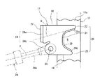
ブラケット前面20は、図2及び図3に示すように、ブラケット前面20の大部分を占め、ブラケット後面24側へ向かう凹部Hを形成する連続湾曲面21と、連続湾曲面21とブラケット上面18を接続する上部円弧面22と、連続湾曲面21とブラケット下面19を接続する下部円弧面23により形成される。
連続湾曲面21は、ティルトブラケット17がアウタマスト11に固定されている状態では側面視略C字状の面である。
ティルトブラケット17をアウタマスト11に固定する溶接部29が連続湾曲面21に沿って連続的に形成されている。
2 and 3, the
The continuous
A welded
溶接部29は所定の幅を持ち、溶接部29の長手方向の端部である溶接端29a、29bは連続湾曲面21の端部に位置する。
特に、連続湾曲面21において上側の溶接端29aを可能なかぎり前方へ位置させることにより、溶接端29aに対する高応力の発生を抑制することができる。
ティルトブラケット17は連続湾曲面21に沿う溶接部29のみによりアウタマスト11に固定され、ティルトブラケット17に他の部位に溶接部は形成されない。
The welded
In particular, the occurrence of high stress on the
The
ここで、連続湾曲面21について図3に基づき詳しく説明する。
連続湾曲面21は、上側の端部(点E)から後方中央へ向けて傾斜して延在する直線状の上部傾斜面部21aと、下側の端部(点F)から後方中央部へ向けて傾斜して延在する直線状の下部傾斜面部21bと、上部傾斜面部21a及び下部傾斜面部21bの間においてブラケット上面18と垂直な面を形成する中間垂直面部21cと、上部傾斜面部21aと中間垂直面部21cとを結ぶ上曲面部21dと、下部傾斜面部21bと中間垂直面部21cとを結ぶ下曲面部21eとにより形成されている。
Here, the continuous
The continuous
ティルトシリンダ28がアウタマスト11の姿勢を直立に保持するとき、連続湾曲面21における上部傾斜面部21aの傾斜方向(一点鎖線Qにより図示)と、ティルトシリンダ28のロッド28aの軸心方向(一点鎖線Pにより図示)が互いにほぼ一致する。
ロッド28aの軸心方向は、ティルトシリンダ28の作動により進退するロッド28aの進退方向と同じ方向である。
上部傾斜面部21aの傾斜方向とロッド28a端の軸心方向をほぼ一致させることにより、溶接部29における高応力の発生を抑制し、その結果、溶接部29の長さを短縮させることが可能になる。
連続湾曲面21における上曲面部21d及び下曲面部21eの曲率は、溶接部29に作用する応力分散のためにできるだけ大きく設定されることが好ましい。
When the
The axial center direction of the
By making the inclination direction of the upper
It is preferable that the curvatures of the upper
この実施形態に係るマスト装置10の作用について説明する。
マスト装置10はティルトシリンダ28の作動により前後に傾動される。
このとき、マスト装置10におけるティルトブラケット17には、ティルトシリンダ28のロッド28a端を介してロッド28aの軸心方向に作用する荷重が発生する。
The operation of the
The
At this time, a load acting on the axial direction of the
ロッド28aの軸心方向の荷重がティルトブラケット17に発生するとき、溶接部29には荷重に応じた応力が発生し、この応力は溶接部29に沿って分布される。
溶接部29の上下方向の長さは、上曲面部21d及び下曲面部21eを含む連続湾曲面21に沿って連続的に形成されていることから、溶接部29に作用する応力の一部は上曲面部21d及び下曲面部21eに分散され、両曲面部21d、21eにおいて過度の応力集中は回避される。
上部傾斜面部21aの傾斜方向は、溶接部29における応力が作用する傾斜方向と一致するから、上部傾斜面部21aに沿う溶接部29の部位は、上部傾斜面部21aの傾斜方向と一致する応力が比較的高くてもこの応力に対抗でき、溶接端29aにおける過度の応力集中は回避される。
When a load in the axial direction of the
Since the vertical length of the welded
Since the inclination direction of the upper
なお、溶接端29aの位置が、荷重の入力元となる軸孔25から前方へ遠ざかるにつれて溶接端29aに作用する応力は低減する。
さらに、連続湾曲面21に沿う溶接部29が連続的に形成されていることから、ロッド28aの軸心方向だけでなくティルトブラケット17への上下前後の荷重に基づく応力が溶接部29に作用しても、溶接部29がこの応力に対抗して、ティルトブラケット17はアウタマスト11に対して強固に固定された状態を維持する。
In addition, the stress which acts on the
Furthermore, since the welded
次に、この実施形態のティルトブラケット17の製作時における材料取りについて説明する。
図4に示すように、ティルトブラケット17は板状部材としての方形状の金属板Mの打ち抜き又は切り抜きにより得られる。
金属板Mの一辺の長さをブラケット上面18とブラケット下面19との間の距離と同じ長さに設定すると、打ち抜き又は切り抜きの際に、図4に示すように無駄となる余剰部m1、m2、m3(図4においてハッチングに示す各領域)が発生する。
Next, the material removal at the time of manufacture of the
As shown in FIG. 4, the
If the length of one side of the metal plate M is set to the same length as the distance between the bracket
余剰部m1は、ブラケット前面20を構成する連続湾曲面21、上部円弧面22及び下部円弧面23を形成することにより生じる余剰部である。
また、余剰部m2は、ティルトブラケット17においてブラケット後面24に接続面24bが形成されることにより生じる余剰部であり、余剰部m3は軸孔25を形成することにより生じる余剰部である。
この実施形態では、ブラケット上面18とブラケット下面19が互いに平行であり、金属板Mの総面積に締める余剰部m1〜m3の合計面積の割合は、従来のティルトブラケットを製作する場合に発生する余剰部と比較して低くすることができ、材料の無駄が抑制される。
The surplus portion m <b> 1 is a surplus portion generated by forming the continuous
In addition, the surplus portion m2 is a surplus portion generated by forming the
In this embodiment, the bracket
この実施形態によれば、以下の効果を奏する。
(1)溶接部29が連続湾曲面21に沿って連続的に形成されていることから、溶接部29における応力を連続湾曲面21に沿って分布させることができる。溶接部29の溶接端29aが連続湾曲面21の前側となる端部に位置し、上部傾斜面部21aの傾斜方向は、溶接部29における応力が作用する傾斜方向と一致するから、溶接端29aにおける応力集中を発生させにくくすることができる。また、溶接部29における過度の応力集中を回避することができる。
According to this embodiment, the following effects can be obtained.
(1) Since the welded
(2)溶接部29をブラケット前面20における連続湾曲面21に沿って設けるだけで、ティルトブラケット17における溶接強度の向上と溶接部29の長さの短縮化とを両立させることができる。
(2) By only providing the welded
(3)溶接部29はブラケット前面20にのみ設けるだけで済むことから、ティルトブラケット17のブラケット上面18及びブラケット下面19を互いに平行とすることができる。ブラケット上面18及びブラケット下面19が互いに平行なティルトブラケット17の形状とすることにより、ティルトブラケット17は板状材料に対する材料取りの歩留まり向上に適した形状とすることができる。
(3) Since the welded
(4)ティルトビーム27の下位に軸孔25を配置すると、ティルトビーム27の上位に軸孔25を配置させた場合と比較して、大きな荷重がティルトブラケット17に作用するが、連続湾曲面21に沿う溶接部29の形成により、従来よりもティルトブラケット17における溶接強度が向上されていることから、ティルトブラケット17は荷重に基づく応力に対抗することができる。従って、マスト装置10の条件等に応じて軸孔25をティルトビーム27の上位又は下位に配置することができ、マスト装置10の設計自由度が向上する。
(4) When the
(5)この実施形態のマスト装置10では、連続湾曲面21に沿う溶接部29を形成することにより、ティルトブラケット17における溶接強度が向上し、従来のマスト装置のようにブラケット前面20以外に溶接部を設ける必要がない。このため、溶接作業に係る作業時間を低減することができる。
(5) In the
(6)ティルトブラケット17における連続湾曲面21に沿う溶接部29を形成するから、溶接部29の長さは従来よりも短くすることができ、溶接作業に必要な手間や時間を抑制することができる。また、曲率の大きな曲面を含む連続湾曲面21であることから、溶接ロボット等を用いた自動溶接による溶接作業を比較的採用し易い。
(6) Since the welded
(7)この実施形態に係るティルトブラケット17は、両板面が平坦面の金属板Mを打ち抜きや切り抜きにより得ることができ、少なくとも、金属板Mの曲げ加工を必要とせず、他部品を使用しないのでティルトブラケット17の製作が従来よりも簡単である。
(7) The
(別例)
次に、別例に係るティルトブラケット37を用いた場合について説明する。
図5は第2の実施形態に係るティルトブラケット37を示す側面図である。
ここでは、上記の実施形態と共通する要素については符号を共通して用い、上記の実施形態の説明を援用する。
図5に示すように、アウタマスト11における主壁部11aの外側面にティルトブラケット37が固定されている。
(Another example)
Next, the case where the
FIG. 5 is a side view showing a
Here, the same reference numerals are used for elements that are common to the above embodiment, and the description of the above embodiment is used.
As shown in FIG. 5, a
ティルトブラケット37は、互いに平行となるブラケット上面38とブラケット下面39とを有する。
ティルトブラケット37は、連続湾曲面41、上部円弧面42及び下部円弧面43を備えるブラケット前面40と、ティルトシリンダ28を臨み、ティルトビーム固定面44a及び接続面44bを有するブラケット後面44とを有する。
この別例ではブラケット前面40を形成する連続湾曲面41に特徴があり、連続湾曲面41は、図5に示すようにブラケット上面38とブラケット下面39との間の上下方向において上下対称である。
つまり、連続湾曲面41は、図5において説明の便宜上設定した水平軸Rを中心に上下対称となっている。
The
The
This another example is characterized by a continuous
That is, the continuous
従って、ティルトシリンダ28がティルトビーム27より上に配置される別の種類のアウトマストにティルトブラケット37を用いることが可能である。
ティルトブラケット37の天地を逆にして別の種類のアウタマストに固定しても、下部傾斜面部41b、中間面部41c、下曲面部41e及び下部円弧面43が上側に配置され、これら41b、41c、41eは、天地を逆にしない場合の上部円弧面42と、上部傾斜面部41aと、上曲面部41dと同じ位置となる。
ティルトブラケット37の天地を逆にして別の種類のアウタマストに固定する場合、下部傾斜面部41bが上側に位置し、下部傾斜面部41bの傾斜方向はロッド28aの軸心方向と一致する。
溶接部49は連続湾曲面41に沿って形成されて、溶接端49aは上部円弧面42寄りに位置し、溶接端49bは下部円弧面43寄りに位置する。
Accordingly, it is possible to use the
Even if the top and bottom of the
When the
The welded
この別例によれば、ティルトブラケット37における連続湾曲面41が上下対称であることから、ティルトブラケット37の接続面44bを上の位置とし、ティルトビーム固定面44aを下の位置となるように、ティルトブラケット37の天地を逆にして用いることにより、ティルトシリンダ28がティルトビーム27より上に配置される別の種類のアウトマストにティルトブラケット37を適用することができる。
このため、マスト装置10の種類に応じてティルトブラケット37の固定のやり方を変更することができ、ティルトブラケット37の固定に対する汎用度を高めることができる。
According to this alternative example, since the continuous
For this reason, the method of fixing the
なお、本発明は、上記した実施形態に限定されるものではなく発明の趣旨の範囲内で種々の変更が可能であり、例えば、次のように変更してもよい。
上記の実施形態では、軸支部としてティルトブラケットに軸孔を設け、ティルトシリンダのロッド端がこの軸孔に挿入される軸部を有する場合について説明したが、ティルトブラケットに軸部を設け、ロッド端に軸部が挿入される軸孔を設けるようにしてもよい。
The present invention is not limited to the above-described embodiment, and various modifications are possible within the scope of the gist of the invention. For example, the following modifications may be made .
In the above embodiment, the case where the tilt bracket is provided with the shaft hole as the shaft support portion and the rod end of the tilt cylinder has the shaft portion inserted into the shaft hole has been described. However, the tilt bracket is provided with the shaft portion and the rod end A shaft hole into which the shaft portion is inserted may be provided.
10 マスト装置
11 アウタマスト
17、37 ティルトブラケット
18、38 ブラケット上面
19、39 ブラケット下面
20、40 ブラケット前面
21、41 連続湾曲面
21a、41a 上部傾斜面部
21b、41b 下部傾斜面部
21c、41c 中間垂直面部
21d、41d 上曲面部
21e、41e 下曲面部
22、42 上部円弧面
23、43 下部円弧面
24、44 ブラケット後面
25 軸孔
27 ティルトビーム
28 ティルトシリンダ
28a ロッド
29、49 溶接部
29a、29b、49a、49b 溶接端
H 凹部
M 金属板
m1、m2、m3 余剰部
10
Claims (3)
前記ティルトブラケットは、板面が平坦な平板材料により形成されるとともに、互いに平行なブラケット上面及びブラケット下面と、前記ティルトブラケットを前記アウタマストに固定する溶接部が形成されるブラケット前面と、前記ティルトシリンダを臨むブラケット後面と、前記ロッド端を軸支する軸支部と、を有し、
前記ブラケット前面は、ブラケット後面側へ向かう凹部を形成する連続湾曲面を有し、
前記連続湾曲面は、前記ロッドの軸心方向と一致する直線状の上部傾斜面部と、後方中央部へ向けて傾斜して延在する下部傾斜面部と、前記上部傾斜面部及び前記下部傾斜面部の間において面を形成する中間垂直面部と、前記上部傾斜面部と前記中間垂直面部とを結ぶ上曲面部と、前記下部傾斜面部と前記中間垂直面部とを結ぶ下曲面部とにより形成され、
前記溶接部は、前記上部傾斜面部と、前記下部傾斜面部と、前記中間垂直面部と、前記上曲面部と、前記下曲面部に沿って連続的に形成されることを特徴とするフォークリフトにおけるマスト装置。 In a forklift having a pair of left and right outer masts that are provided at the front of the vehicle body and tilted back and forth by a tilt cylinder, and a tilt bracket that is fixed to the outer surface of the outer mast by welding and pivotally supports the rod end of the tilt cylinder. A mast device,
The tilt bracket is formed of a flat plate material having a flat plate surface, a bracket upper surface and a bracket lower surface that are parallel to each other, a bracket front surface on which a weld portion that fixes the tilt bracket to the outer mast is formed, and the tilt cylinder A bracket rear surface that faces the shaft, and a shaft support portion that pivotally supports the rod end,
The bracket front surface has a continuous curved surface that forms a recess toward the bracket rear surface side,
The continuous curved surface includes a linear upper inclined surface portion coinciding with the axial direction of the rod, a lower inclined surface portion extending obliquely toward the rear center portion, the upper inclined surface portion, and the lower inclined surface portion. An intermediate vertical surface portion that forms a surface in between, an upper curved surface portion that connects the upper inclined surface portion and the intermediate vertical surface portion, and a lower curved surface portion that connects the lower inclined surface portion and the intermediate vertical surface portion,
The weld mast the forklift to said upper inclined surface, and the lower inclined surface portion, said intermediate vertical surface portion, and the upper curved surface portion, characterized in that it is continuously formed along the lower curved portion apparatus.
Priority Applications (2)
| Application Number | Priority Date | Filing Date | Title |
|---|---|---|---|
| JP2007243887A JP5233218B2 (en) | 2007-09-20 | 2007-09-20 | Mast device in forklift |
| EP20080164686 EP2039647B1 (en) | 2007-09-20 | 2008-09-19 | Mast assembly for a forklift truck |
Applications Claiming Priority (1)
| Application Number | Priority Date | Filing Date | Title |
|---|---|---|---|
| JP2007243887A JP5233218B2 (en) | 2007-09-20 | 2007-09-20 | Mast device in forklift |
Publications (2)
| Publication Number | Publication Date |
|---|---|
| JP2009073618A JP2009073618A (en) | 2009-04-09 |
| JP5233218B2 true JP5233218B2 (en) | 2013-07-10 |
Family
ID=40090333
Family Applications (1)
| Application Number | Title | Priority Date | Filing Date |
|---|---|---|---|
| JP2007243887A Expired - Fee Related JP5233218B2 (en) | 2007-09-20 | 2007-09-20 | Mast device in forklift |
Country Status (2)
| Country | Link |
|---|---|
| EP (1) | EP2039647B1 (en) |
| JP (1) | JP5233218B2 (en) |
Families Citing this family (3)
| Publication number | Priority date | Publication date | Assignee | Title |
|---|---|---|---|---|
| DE102013004434A1 (en) * | 2013-03-15 | 2014-09-18 | Jungheinrich Aktiengesellschaft | Mast for a truck |
| JP6365366B2 (en) | 2015-03-17 | 2018-08-01 | 株式会社豊田自動織機 | Forklift cargo handling equipment |
| CN107522141B (en) * | 2017-09-25 | 2023-12-22 | 安徽合力股份有限公司 | Positioning device for assembling lower cross beam assembly of outer door frame |
Family Cites Families (10)
| Publication number | Priority date | Publication date | Assignee | Title |
|---|---|---|---|---|
| JPS58181605U (en) * | 1982-05-31 | 1983-12-03 | 日産ディーゼル工業株式会社 | Torque closed bracket for vehicle axle |
| JPH0754003Y2 (en) * | 1989-03-22 | 1995-12-13 | いすゞ自動車株式会社 | Bracket welded structure |
| JPH085627B2 (en) | 1990-10-12 | 1996-01-24 | 株式会社豊田自動織機製作所 | Tilt cylinder mounting structure for forklift |
| JPH05338996A (en) * | 1992-06-10 | 1993-12-21 | Toyota Autom Loom Works Ltd | Structure of connection part between mast and tilt cylinder |
| JPH09227095A (en) * | 1996-02-22 | 1997-09-02 | Toyota Autom Loom Works Ltd | Tilt bracket and outer mast |
| JP3985347B2 (en) * | 1998-07-07 | 2007-10-03 | 株式会社豊田自動織機 | Tilt cylinder coupling structure |
| JP4075145B2 (en) * | 1998-07-29 | 2008-04-16 | 株式会社豊田自動織機 | Forklift cargo handling equipment |
| JP2000255996A (en) * | 1999-03-09 | 2000-09-19 | Komatsu Forklift Co Ltd | Tilt stay structure for forklift mast |
| JP4537775B2 (en) * | 2004-06-25 | 2010-09-08 | Tcm株式会社 | Mast tilt device |
| JP2006069712A (en) * | 2004-08-31 | 2006-03-16 | Komatsu Forklift Co Ltd | Supporting arm for hinged fork |
-
2007
- 2007-09-20 JP JP2007243887A patent/JP5233218B2/en not_active Expired - Fee Related
-
2008
- 2008-09-19 EP EP20080164686 patent/EP2039647B1/en not_active Not-in-force
Also Published As
| Publication number | Publication date |
|---|---|
| EP2039647B1 (en) | 2011-05-18 |
| JP2009073618A (en) | 2009-04-09 |
| EP2039647A1 (en) | 2009-03-25 |
Similar Documents
| Publication | Publication Date | Title |
|---|---|---|
| JP5233218B2 (en) | Mast device in forklift | |
| JP6529100B1 (en) | Industrial vehicle | |
| JP6372057B2 (en) | Trailing arm mounting structure | |
| CN103938666A (en) | Working machine | |
| JP2007196875A (en) | Steering column bracket | |
| JP2017088099A (en) | Joint structure of vehicle skeleton members | |
| JP2001121214A (en) | Press brake crowning device | |
| JP7193490B2 (en) | Joint structure of two channel plates | |
| CN109505318A (en) | Excavator boom and excavator | |
| JP5364353B2 (en) | Boom hoisting cylinder mounting structure | |
| JP6024602B2 (en) | Rear pillar structure | |
| JP4946116B2 (en) | Forklift mast assembly | |
| JP2006312213A (en) | Press cutting apparatus and press cutting method | |
| JP5256670B2 (en) | Mast support device | |
| JP6202376B2 (en) | Apron side member reinforcement structure | |
| CN213008376U (en) | Vehicle body structure | |
| JP3134434U (en) | Mast support structure | |
| JP6220810B2 (en) | Seat back frame | |
| JP4669387B2 (en) | Stiffener welding method for ship structures | |
| JP4048308B2 (en) | Industrial vehicle tank | |
| JP2023080677A (en) | Intersection structure of chassis frame | |
| CN210555113U (en) | Subframe support structure and automobile | |
| JP7045245B2 (en) | Roof support structure | |
| JP2002038512A (en) | Welded structure of boss and bracket and its welding method | |
| JPH09227094A (en) | Tilt beam |
Legal Events
| Date | Code | Title | Description |
|---|---|---|---|
| A621 | Written request for application examination |
Free format text: JAPANESE INTERMEDIATE CODE: A621 Effective date: 20090930 |
|
| A977 | Report on retrieval |
Free format text: JAPANESE INTERMEDIATE CODE: A971007 Effective date: 20111227 |
|
| A131 | Notification of reasons for refusal |
Free format text: JAPANESE INTERMEDIATE CODE: A131 Effective date: 20120529 |
|
| A521 | Request for written amendment filed |
Free format text: JAPANESE INTERMEDIATE CODE: A523 Effective date: 20120723 |
|
| TRDD | Decision of grant or rejection written | ||
| A01 | Written decision to grant a patent or to grant a registration (utility model) |
Free format text: JAPANESE INTERMEDIATE CODE: A01 Effective date: 20130226 |
|
| A61 | First payment of annual fees (during grant procedure) |
Free format text: JAPANESE INTERMEDIATE CODE: A61 Effective date: 20130311 |
|
| R151 | Written notification of patent or utility model registration |
Ref document number: 5233218 Country of ref document: JP Free format text: JAPANESE INTERMEDIATE CODE: R151 |
|
| FPAY | Renewal fee payment (event date is renewal date of database) |
Free format text: PAYMENT UNTIL: 20160405 Year of fee payment: 3 |
|
| LAPS | Cancellation because of no payment of annual fees |