JP5225040B2 - Seamless capsule manufacturing equipment - Google Patents
Seamless capsule manufacturing equipment Download PDFInfo
- Publication number
- JP5225040B2 JP5225040B2 JP2008297288A JP2008297288A JP5225040B2 JP 5225040 B2 JP5225040 B2 JP 5225040B2 JP 2008297288 A JP2008297288 A JP 2008297288A JP 2008297288 A JP2008297288 A JP 2008297288A JP 5225040 B2 JP5225040 B2 JP 5225040B2
- Authority
- JP
- Japan
- Prior art keywords
- liquid
- distributor
- manufacturing apparatus
- tube
- capsule
- Prior art date
- Legal status (The legal status is an assumption and is not a legal conclusion. Google has not performed a legal analysis and makes no representation as to the accuracy of the status listed.)
- Expired - Fee Related
Links
Images


Classifications
-
- A—HUMAN NECESSITIES
- A23—FOODS OR FOODSTUFFS; TREATMENT THEREOF, NOT COVERED BY OTHER CLASSES
- A23P—SHAPING OR WORKING OF FOODSTUFFS, NOT FULLY COVERED BY A SINGLE OTHER SUBCLASS
- A23P10/00—Shaping or working of foodstuffs characterised by the products
- A23P10/30—Encapsulation of particles, e.g. foodstuff additives
-
- A—HUMAN NECESSITIES
- A61—MEDICAL OR VETERINARY SCIENCE; HYGIENE
- A61J—CONTAINERS SPECIALLY ADAPTED FOR MEDICAL OR PHARMACEUTICAL PURPOSES; DEVICES OR METHODS SPECIALLY ADAPTED FOR BRINGING PHARMACEUTICAL PRODUCTS INTO PARTICULAR PHYSICAL OR ADMINISTERING FORMS; DEVICES FOR ADMINISTERING FOOD OR MEDICINES ORALLY; BABY COMFORTERS; DEVICES FOR RECEIVING SPITTLE
- A61J3/00—Devices or methods specially adapted for bringing pharmaceutical products into particular physical or administering forms
- A61J3/07—Devices or methods specially adapted for bringing pharmaceutical products into particular physical or administering forms into the form of capsules or similar small containers for oral use
Landscapes
- Health & Medical Sciences (AREA)
- Chemical & Material Sciences (AREA)
- Life Sciences & Earth Sciences (AREA)
- General Health & Medical Sciences (AREA)
- Medicinal Chemistry (AREA)
- Pharmacology & Pharmacy (AREA)
- Animal Behavior & Ethology (AREA)
- Public Health (AREA)
- Veterinary Medicine (AREA)
- Polymers & Plastics (AREA)
- Food Science & Technology (AREA)
- Engineering & Computer Science (AREA)
- Medical Preparation Storing Or Oral Administration Devices (AREA)
- Formation And Processing Of Food Products (AREA)
Description
本発明は、食品や健康食品、医薬品、香料等の充填物質を、ゼラチンや寒天等を含む皮膜によって被覆するシームレスカプセルの大量生産用製造装置に関する。 The present invention relates to an apparatus for mass production of seamless capsules in which filling substances such as foods, health foods, pharmaceuticals and fragrances are coated with a film containing gelatin, agar or the like.
医薬品等に用いられるシームレスカプセルの多くは、従来より滴下法と呼ばれる製法によって製造されている。この滴下法は多重ノズルを用いて行われ、2層のカプセルの場合、内側にカプセル芯液の吐出口、外側に皮膜液の吐出口を配した二重ノズルが使用される。芯液と皮膜液は各ノズル先端から硬化用液中に放出され、放出された液滴はその表面張力によって球形となる。そして、この液滴が一定速度で還流する硬化用液中で冷却、凝固し、球形のシームレスカプセルが形成される。 Many of seamless capsules used for pharmaceuticals and the like are conventionally produced by a production method called a dropping method. This dropping method is performed using multiple nozzles. In the case of a two-layer capsule, a double nozzle is used in which a capsule core liquid discharge port is provided on the inner side and a coating liquid discharge port is provided on the outer side. The core liquid and the coating liquid are discharged into the curing liquid from the tip of each nozzle, and the discharged liquid droplets become spherical due to the surface tension. Then, the droplets are cooled and solidified in a curing liquid that is refluxed at a constant speed, and spherical seamless capsules are formed.
特許文献1にはこのようなシームレスカプセルの製造装置が記載されており、そこでは、皮膜液と芯液は、それぞれ別個のポンプにて多重ノズルに供給され、硬化用液中に吐出される。但し、当該装置では、多重ノズルが1個のため、カプセルの生産量は稼働時間に比例し、生産量を増やす場合には、稼働時間を増やすか、機械を増設する必要がある。そこで、シームレスカプセルの大量生産用に、特許文献2のような複数個の多重ノズルを持つ装置が提案されており、そこでは、複数個のノズルが接続されたチャンバが使用される。このチャンバには、皮膜液供給用チャンバと芯液用チャンバがあり、各チャンバには、皮膜液と芯液がそれぞれ別個のポンプにて供給される。各ノズルには両チャンバから皮膜液と芯液が供給され、硬化用液中に両液による液滴が吐出されてシームレスカプセルの大量生産が行われる。
しかしながら、特許文献2のような装置は、1台でシームレスカプセルを大量生産すること自体は可能であるが、出来上がったシームレスカプセルの粒径がばらついてしまい、非常に生産効率が悪いという問題があった。すなわち、まず第1に、前記装置はノズルをチャンバ内に連設し、チャンバ横から一方向に液を供給する構造となっているため、液供給口からの距離の違いにより、ノズルによってカプセルの粒径に差違が生じるという問題があった。一般に、液体は、抵抗が小さい部分に多く流れ、抵抗が大きい部分には少なく流れる性質があることから、特許文献2のような装置構造の場合、液供給口から近いノズルの液流量は多くなり、遠いノズルは液流量が少なくなる傾向がある。このため、液供給口に近いノズルから生成されたシームレスカプセルは粒径が大きくなり、液供給口から遠いノズルから生成されたシームレスカプセルは粒径が小さくなってしまう。
However, although the device as in
また、第2に、特許文献2の装置は振動器がなく、粒径制御はポンプからの流量制御に依存しているため、ポンプの脈動等により、1つの多重ノズルからできるカプセルの粒径にもバラツキが生じてしまうという問題もあった。つまり、特許文献2のような装置では、各ノズル毎に粒径にバラツキが生じるのみならず、ノズル単体でも粒径にバラツキが生じる。シームレスカプセルは、得られる粒径が均一で非常に歩留まりが良いことが特徴の1つとなっており、このようにノズル全体に亘ってカプセル粒径に差違が生じると、粒度分布に大きい幅が生じ、歩留まりが低下し大量のロスが生じるという問題があり、その対策が求められていた。
Second, since the device of
さらに、特許文献2の装置は、皮膜液等を供給する経路が密閉された閉回路方式であるため、時間の経過とともに各液に含まれる空気がチャンバ内に蓄積する。チャンバ内に空気が溜まると、チャンバ内の液面が滞留した空気によって下がり、各ノズルの液導入口よりも低くなってカプセルの生産が行えなくなる。このため、特許文献2のような装置では、チャンバ等を解体して空気を抜く作業が必要となり、その分、生産効率が低下するという問題もあった。
Furthermore, since the apparatus of
なお、この空気溜まりに関しては、特許文献1の装置においても粒径のバラツキや生産効率低下の原因となるという問題がある。すなわち、特許文献1の装置にも空気抜きが存在しないため、ある程度時間が経過するとノズル頭頂部にある加振用の膜の下に空気溜まりができてしまう。この空気溜まりは振動器の振動を吸収してしまう性質があり、空気溜まりが大きくなると加振状態にムラが生じてしまい、粒径にバラツキが生じるおそれがある。このため、特許文献1のような装置では、時折手作業にて空気抜きの作業を行っており、振動器を外してノズルを上下反転させることにより、ノズル内の空気を押し出している。そして、空気抜き作業の後、改めて振動器をセットし、カプセル製造を再開する。しかしながら、このような空気抜き作業は手作業であるため、非常に手間が掛かる上に、ノズルを落としてしまうリスクある。また、空気抜き作業中や再セットの間はシームレスカプセルの生産は一時中断せざるを得ず、生産効率低下の原因となる。 In addition, regarding this air reservoir, there is a problem that even the apparatus of Patent Document 1 causes a variation in particle diameter and a decrease in production efficiency. That is, since there is no air venting in the apparatus of Patent Document 1, an air pocket is formed under the vibration film at the top of the nozzle after a certain amount of time has passed. This air reservoir has the property of absorbing the vibration of the vibrator, and when the air reservoir becomes large, the vibration state is uneven, and there is a possibility that the particle size varies. For this reason, in an apparatus such as Patent Document 1, air is occasionally removed manually, and the air in the nozzle is pushed out by removing the vibrator and turning the nozzle upside down. After the air venting operation, the vibrator is set again, and capsule production is resumed. However, since such air venting is a manual operation, it is very time-consuming and there is a risk of dropping the nozzle. In addition, the production of seamless capsules must be temporarily suspended during the air venting operation or during the resetting, which causes a reduction in production efficiency.
本発明の目的は、均一な粒径のシームレスカプセルを安定的に大量生産可能なシームレスカプセル製造装置を提供することにある。 An object of the present invention is to provide a seamless capsule manufacturing apparatus capable of stably mass-producing seamless capsules having a uniform particle size.
本発明のシームレスカプセル製造装置は、複数個のノズルに対してポンプによりカプセル形成用液を供給し、前記ノズルから硬化用液が流通するカプセル形成管内に液滴を吐出してシームレスカプセルを製造するカプセル製造装置であって、前記各ノズルに接続された複数本のチューブと、前記チューブと接続され、前記ポンプから供給される前記カプセル形成用液が導入されると共に、該カプセル形成用液を前記チューブを介して前記各ノズルに分配供給するディストリビュータとを有することを特徴とする。 The seamless capsule manufacturing apparatus of the present invention supplies a capsule-forming liquid to a plurality of nozzles by a pump, and discharges droplets from the nozzles into a capsule-forming tube through which a hardening liquid flows to manufacture seamless capsules. A capsule manufacturing apparatus, wherein a plurality of tubes connected to each of the nozzles, the capsule forming liquid connected to the tubes and supplied from the pump are introduced, and the capsule forming liquid is And a distributor that distributes and supplies each nozzle through a tube.
本発明にあっては、ポンプとノズルの間にディストリビュータを介在させ、ディストリビュータから各ノズルに対しカプセル形成用液を分配供給する。これにより、1つのポンプから複数のノズルにカプセル形成用液を均一に供給できる。すなわち、各ノズルに供給されるカプセル形成用液の流速や流量がほぼ同一に揃えられ、ノズル間での流量差が少なくなり、各ノズルにて形成されるカプセルの粒径差が抑えられる。 In the present invention, a distributor is interposed between the pump and the nozzle, and the capsule forming liquid is distributed and supplied from the distributor to each nozzle. Thereby, the capsule forming liquid can be uniformly supplied from a single pump to a plurality of nozzles. That is, the flow rate and flow rate of the capsule forming liquid supplied to each nozzle are almost the same, the flow rate difference between the nozzles is reduced, and the particle size difference of the capsules formed by each nozzle is suppressed.
前記シームレスカプセル製造装置において、ディストリビュータ内にカプセル形成用液が貯留される液溜まり部を設けても良く、これにより、ディストリビュータ内にバッファ機能を持つ部位が形成され、チューブに対して安定的にカプセル形成用液を供給できる。また、前記チューブを同一の長さに設定しても良く、これにより、ノズルに対し均一な液量を供給でき、ノズル同士の流量差が抑えられる。 In the seamless capsule manufacturing apparatus, a liquid reservoir for storing the capsule forming liquid may be provided in the distributor, whereby a portion having a buffer function is formed in the distributor, and the capsule is stably provided to the tube. A forming solution can be supplied. Moreover, the said tube may be set to the same length, and this can supply a uniform liquid quantity with respect to a nozzle and the flow volume difference between nozzles is suppressed.
さらに、ディストリビュータに該ディストリビュータ内に溜まった空気を排出する空気抜き装置を設けても良く、これにより、装置を長時間停止させることなく容易に空気抜きを行うことができる。この場合、空気が溜まり易いディストリビュータ頭頂部に空気抜き装置を配置することが好ましい。加えて、当該ディストリビュータに複数本のチューブが接続される複数個のチューブ孔を設け、各チューブ孔と空気抜き装置が取り付けられる空気抜き孔とをそれぞれ等距離に配置しても良い。 Further, the distributor may be provided with an air vent device for discharging the air accumulated in the distributor, whereby the air can be easily vented without stopping the device for a long time. In this case, it is preferable to arrange an air venting device at the top of the distributor where air tends to accumulate. In addition, a plurality of tube holes to which a plurality of tubes are connected may be provided in the distributor, and each tube hole and the air vent hole to which the air vent device is attached may be arranged at equal distances.
また、ディストリビュータの液溜まり部上方に空気溜まりを設けても良く、この空気溜まりにより、カプセル形成用液の脈動を吸収することができる。この場合、チューブをディストリビュータ内に導入し、その先端部を液溜まり部に貯留されたカプセル形成用液中に浸漬しても良い。 Further, an air reservoir may be provided above the liquid reservoir of the distributor, and the pulsation of the capsule forming liquid can be absorbed by the air reservoir. In this case, the tube may be introduced into the distributor, and the tip thereof may be immersed in the capsule forming liquid stored in the liquid reservoir.
一方、当該ディストリビュータに、カプセル形成用液に対して振動を付与する振動器をさらに設けても良い。その際、当該振動器をディストリビュータに取り付けられた可撓性の振動膜を介してディストリビュータに接続するようにしても良い。また、当該ディストリビュータに複数本のチューブが接続される複数個のチューブ孔を設け、前記振動膜を各チューブ孔と等距離の位置に配置しても良く、これにより、各チューブ孔に対し同等に振動が伝わり、各ノズルにて形成されるカプセルの粒径差が抑えられる。 On the other hand, the distributor may further be provided with a vibrator for applying vibration to the capsule forming liquid. At that time, the vibrator may be connected to the distributor via a flexible vibration film attached to the distributor. Further, the distributor may be provided with a plurality of tube holes to which a plurality of tubes are connected, and the vibrating membrane may be arranged at a position equidistant from each tube hole. Vibration is transmitted and the particle size difference of the capsule formed by each nozzle is suppressed.
さらに、ノズル先端に取り付けられカプセル形成管内にカプセル形成用液を吐出するノズルチップにチューブを直接接続しても良く、これにより、ディストリビュータとノズルチップの間における径変化がなくなり、液速低下による気泡滞留を防止できる。従って、気泡による振動ムラを防止でき、カプセル粒径のバラツキも抑えられる。 Furthermore, the tube may be directly connected to the nozzle tip attached to the tip of the nozzle and discharging the capsule-forming liquid into the capsule-forming tube. Retention can be prevented. Therefore, vibration unevenness due to air bubbles can be prevented, and variations in capsule particle size can be suppressed.
本発明のシームレスカプセル製造装置によれば、複数個のノズルを使用してシームレスカプセルを製造するカプセル製造装置にて、ポンプから供給されるカプセル形成用液が導入されると共に、各ノズルに対してカプセル形成用液を分配供給するディストリビュータとを設けたので、1つのポンプから複数のノズルにカプセル形成用液を均一に供給することができ、ノズル間の流量差を小さく抑えることが可能なる。このため、各ノズル間のカプセル粒径のバラツキが抑えられ、均一な粒径のシームレスカプセルを安定的に大量生産することが可能となる。 According to the seamless capsule manufacturing apparatus of the present invention, in the capsule manufacturing apparatus that manufactures seamless capsules using a plurality of nozzles, the capsule forming liquid supplied from the pump is introduced, and for each nozzle Since the distributor for supplying and supplying the capsule forming liquid is provided, the capsule forming liquid can be uniformly supplied from a single pump to a plurality of nozzles, and the flow rate difference between the nozzles can be kept small. For this reason, variation in the capsule particle size between the nozzles is suppressed, and it becomes possible to stably mass-produce seamless capsules having a uniform particle size.
以下、本発明の実施例を図面に基づいて詳細に説明する。 Hereinafter, embodiments of the present invention will be described in detail with reference to the drawings.
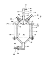
図1は、本発明の実施例1であるシームレスカプセル製造装置の全体構成を示す説明図である。本発明のシームレスカプセル製造装置1は、特許文献1,2のものと同様に、多重構造のノズル2を備えた液中ノズル式の装置となっており、このノズル2からカプセル形成管3内に液滴4を吐出してシームレスカプセルを製造する。
FIG. 1 is an explanatory diagram showing the overall configuration of a seamless capsule manufacturing apparatus that is Embodiment 1 of the present invention. The seamless capsule manufacturing apparatus 1 according to the present invention is a submerged nozzle type apparatus having a
シームレスカプセル製造装置1(以下、適宜、製造装置1と略記する)では、ノズル2は複数個(ここでは4個:ノズル2a〜2d)設けられており、各ノズル2a〜2dには、カプセル形成用液として芯液5と皮膜液6が供給される。ノズル2a〜2dの先端部はカプセル形成管3a〜3d内に挿入されており、各ノズル2a〜2dからは、芯液5と皮膜液6にて形成された二層状態の液滴4が吐出される。この液滴4は、カプセル形成管3a〜3d中の冷却液7によって冷却硬化され、二層の球形シームレスカプセルが形成される。
In the seamless capsule manufacturing apparatus 1 (hereinafter, abbreviated as the manufacturing apparatus 1 as appropriate), a plurality of nozzles 2 (here, four:
シームレスカプセル製造装置1のカプセル形成管3a〜3dは、冷却液供給槽8内に配置されており、冷却液供給槽8から冷却液(硬化用液)7が供給される。冷却液供給槽8には冷却液供給管9が接続されており、冷却液供給槽8内には、冷却液供給管9を介して、冷却タンク11内の冷却液7がポンプ12によって供給される。冷却液供給槽8の外側にはオーバーフロー槽13が設けられており、冷却液供給槽8内の冷却液7は、カプセル形成管3a〜3d内に流入すると共に、その余剰分はオーバーフロー槽13から排出される。オーバーフロー槽13内に流入した冷却液7は、リターン管14を介して冷却タンク11内に戻される。
The
ここで、当該製造装置1では、芯液5と皮膜液6は、それぞれディストリビュータ21,22によって各ノズル2a〜2dに分配供給される。すなわち、芯液5は芯液用タンク15内に貯留され、ポンプ16によってまず芯液用のディストリビュータ21に供給される。そして、ディストリビュータ21から芯液分配チューブ23(23a〜23d)を介して各ノズル2a〜2dに分配される。ディストリビュータ21には、振動器24が組み込まれており、芯液5は振動を付与された状態でノズル2a〜2dに供給される。一方、皮膜液6は皮膜液用タンク17内に貯留され、ポンプ18によってまず皮膜液用のディストリビュータ22に供給される。そして、芯液5と同様に、ディストリビュータ22から皮膜液分配チューブ25(25a〜25d)を介して各ノズル2a〜2dに分配される。
Here, in the manufacturing apparatus 1, the
ディストリビュータ21,22は概ね同様の構造となっているが、ここではまずディストリビュータ21について説明する。図2は芯液用ディストリビュータ21の構成を示す断面図、図3はその要部の分解斜視図である。ディストリビュータ21は、図2,3に示すように、大きく分けて、上部パーツ31、筒パーツ32及び下部パーツ33とから構成されている。ディストリビュータ21,22は、特に明記しない限り、基本的にはステンレス鋼にて形成されている。
上部パーツ31には、共にステンレス鋼にて形成された上部フランジ34と空気抜き装置35が設けられている。上部フランジ34は円板状に形成されており、その中央には、テーパ状の斜面を有する凸部34aが突設されている。凸部34aの外周側には、環状に平板部34bが形成されている。凸部34aの内側はテーパ状の天井面を有する空洞部36となっており、平板部34bには、複数個(ここでは8個)のボルト孔38が等分に貫通形成されている。凸部34aの中央頂部には、空気抜き孔37が貫通形成されている。凸部34aの斜面には、空気抜き孔37を取り囲む形で、チューブ孔39が4個(39a〜39d)等分に貫通形成されている。各チューブ孔39a〜39dは、空気抜き孔37から等角度、等距離に配置されている。
The
なお、チューブ孔39a〜39dを筒パーツ32などに設けることも可能であるが、その様な構造とすると、チューブ孔39a〜39dより上の部分に液が滞留し易くなる。液滞留が生じると、ディストリビュータ22の場合ではあるが、皮膜液6に多く使用されるゼラチンは、長時間高温にさらすとゲル化能力が低下することがあり、極力滞留が生じないような構造が望ましい。このため、当該製造装置1では、ディストリビュータ21,22の構造を共通化するという観点からも、両ディストリビュータ21,22共にチューブ孔39a〜39dを上部パーツ31に配し、芯液5や皮膜液6の滞留を防止している。
It is possible to provide the tube holes 39a to 39d in the
各チューブ孔39a〜39dには、芯液分配チューブ23a〜23dが接続される。芯液分配チューブ23a〜23dは同じ長さに設定されており、それぞれノズル2a〜2dに接続されている。図4はノズル2の構成を示す説明図であり、芯液分配チューブ23a〜23dは、ノズル2の先端に配置されたノズルチップ26に直接接続されている。なお、ノズル2a〜2dは全て同じ構造となっている。ノズル2は、芯液ノズルベース27と、皮膜液ノズルベース28、固定具29とを備えた構成となっており、図4に示すように、ノズルチップ26に接続された芯液分配チューブ23a〜23dが芯液ノズルベース27を通ってノズル2の上端から引き出されている。
The core
皮膜液ノズルベース28には、皮膜液流入口28aが設けられており、皮膜液分配チューブ25a〜25dが接続される。この場合も、各皮膜液分配チューブ25a〜25dは同じ長さに設定されている。皮膜液ノズルベース28の下方側には固定具29が取り付けられている。また、皮膜液ノズルベース28の下端部には、ノズルチップ26を覆う形でノズルキャップ30が取り付けられおり、ノズルキャップ30の先端部には、ノズルチップ26の外周に皮膜液吐出口30aが形成されている。
The coating
ノズル2では、ノズルチップ26の先端から芯液5が、また、皮膜液吐出口30aからは芯液5の周りを取り囲むように皮膜液6が吐出される。このノズル2から吐出された二層液は、芯液5に付与された振動によって適宜液滴4に分断され、カプセル形成管3内に流出する。なお、芯液分配チューブ23a〜23dは、合成樹脂など伝熱効果の低いものを用いることにより、ノズル2内における皮膜液6からの高熱の影響を少なくすることができ、ビフィズス菌など熱に弱いもののカプセル化に有利となる。
In the
空気抜き装置35は、ディストリビュータ21の頭頂部に設置されており、その先端部には空気排出口40が設けられている。図2に示すように、空気抜き装置35の先端部はL字形となっており、空気排出口40は側方に向かって開口している。ディストリビュータ21にて空気抜きを行う場合、芯液5がこぼれ出て来るまで空気抜き作業を行う。このため、ディストリビュータ21では、こぼれ出た芯液5を回収しやすいように、装置先端部をL字形とし、水平方向に延びる延設部41の先端で空気排出口40を開口させている。また、空気排出口40は、空気抜き装置本体42内に形成された流通路43と連通している。流通路43中には、流通路43の流通を制御する開閉弁44が設けられている。装置本体42の中程には開閉弁44のコック45が設けられており、コック45によって開閉弁44を開くと、空気抜き孔37と空気排出口40が連通するようになっている。
The
筒パーツ32は両端が開口した円筒形状となっており、その上端側は、パッキン46を介して上部フランジ34と接続される。筒パーツ32の側部には、芯液供給孔47が貫通形成されている。芯液供給孔47はタップ孔となっており、チューブ取付部48が取り付けられる。チューブ取付部48には芯液供給口48aが開口形成されており、芯液供給チューブ49が接続される。これにより、ディストリビュータ21は、ポンプ16を介して芯液用タンク15と接続される。なお、芯液供給チューブ49と芯液分配チューブ23a〜23dは異なる内径寸法となっており、芯液分配チューブ23a〜23dは芯液供給チューブ49よりも小径となっている。筒パーツ32の内部は空間となっており、芯液供給チューブ49を介して供給される芯液5が貯留される液溜まり部50となる。
The
下部パーツ33は、平板状のベース板51と、ベース板51の下面側に取り付けられる振動膜(メンブレン)52と、ベース板51との間で振動膜52を挟持する押さえ板53を備えている。ベース板51には、上部フランジ34のボルト孔38に対応して、タップ孔54が複数個(ここでは8個)等分に貫通形成されている。タップ孔54には、ボルト孔38を介して挿通ボルト55(ここでは4本使用)が取り付けられる。ベース板51は、筒パーツ32の下端側とパッキン56を介して接続され、挿通ボルト55を締め付けることにより、筒パーツ32は、上部フランジ34とベース板51との間に気密状態で固定される。
The
ベース板51の下面側にはシリコン製の振動膜52が取り付けられ、ベース板51と押さえ板53の間にて挟持される。押さえ板53には、固定用のボルト孔57が複数個(ここでは4個)等分に貫通形成されており、このボルト孔57には、下面側からメンブレン固定ボルト58が挿通される。ベース板51と押さえ板53の間に振動膜52を挟み込み、その状態で、固定ボルト58をボルト孔57からタップ孔54にねじ込む。これにより、ベース板51の下面側に振動膜52が固定される。
A
振動膜52の中央部には、振動伝達用のピン59が取り付けられている。ピン59には、フランジ部61が一体に形成されており、ピン59の先端部には雌ネジ部62が形成されている。振動膜52の中央にはピン孔63が形成されており、ピン孔63に合わせて振動膜52の上面側にセットプレート64を配置する。セットプレート64には雄ネジ部65が形成されており、振動膜52の上面側から雄ネジ部65をピン孔63に挿通し、これをピン59の雌ネジ部62と螺合させる。これにより、ピン59が振動膜52の中央部に固定される。
A
ピン59は、ディストリビュータ21の下方に設置された振動器24に接続される。振動器24は、振動器取付ベース66に取り付けられており、ピン59は、振動器24の上端中央に配置されたピン固定部67に接続固定される。振動器取付ベース66の上方にはディストリビュータ取付ベース68が設けられており、ディストリビュータ21を支持固定するための支持ボルト71が取り付けられている。これに対し、ベース板51の四隅には取付孔72が形成されている。支持ボルト71上には支持ナット73が取り付けられており、取付孔72に支持ボルト71を挿入することにより、ベース板51が支持ナット73によって保持される。そして、ベース板51上に突出した支持ボルト71に、ベース板固定ナット74をさらに取り付けることにより、ディストリビュータ21は、ディストリビュータ取付ベース68上に載置固定される。
The
一方、皮膜液用のディストリビュータ22もディストリビュータ21と概ね同じ構造となっている。図5は皮膜液用ディストリビュータ22の構成を示す断面図である。なお、ディストリビュータ21と同様の部品、部材については同一の符号を付し、その説明は省略する。図5に示すように、まず、ディストリビュータ21には振動器24が取り付けられていない。また、筒パーツ81には皮膜液の供給孔が設けられておらず、下部パーツ82は上部パーツ31と同様の構成となっている。但し、下部パーツ82には空気抜き装置35は取り付けられておらず、それに代えて、皮膜液供給部83が取り付けられている。
On the other hand, the
皮膜液供給部83には、側方に向けて突出配置されたチューブ取付部84が形成されており、その先端部には皮膜液供給口84aが開口形成されている。チューブ取付部84の皮膜液供給口84aには、皮膜液供給チューブ85が接続される。これにより、ディストリビュータ22は、ポンプ18を介して皮膜液用タンク17と接続される。なお、この場合も、皮膜液分配チューブ25a〜25dは皮膜液供給チューブ85よりも小径となっている。筒パーツ81の内部は空間となっており、皮膜液供給チューブ85を介して供給される皮膜液6が貯留される液溜まり部50となる。
A
このようなシームレスカプセル製造装置1では、次のようにしてシームレスカプセルが製造される。まず、ポンプ16,18を作動させ、芯液用タンク15から芯液5を、皮膜液用タンク17から皮膜液6をそれぞれディストリビュータ21,22に供給する。ディストリビュータ21には、芯液供給チューブ49を介して筒パーツ32に芯液5が供給される。また、ディストリビュータ22には、皮膜液供給チューブ85を介して下部パーツ82に皮膜液6が供給される。各ディストリビュータ21,22に供給された芯液5と皮膜液6は、筒パーツ32,81内の液溜まり部50に流入する。液溜まり部50内が各液にて満たされ、液位が上昇し上部フランジ34内の空洞部36に至ると、各液はチューブ孔39a〜39dから流出する。チューブ孔39a〜39dから流出した各液は、各分配チューブ23a〜23d,25a〜25dによってノズル2a〜2dに供給される。
In such a seamless capsule manufacturing apparatus 1, a seamless capsule is manufactured as follows. First, the
このように、本発明による製造装置1では、ポンプ16,18とノズル2の間にディストリビュータ21,22が介在されており、ディストリビュータ21,22を一旦経由してから各ノズル2a〜2dに芯液5や皮膜液6を供給する。この場合、ディストリビュータ21,22には液溜まり部50が設けられており、芯液5や皮膜液6はそこで一旦溜められた後、各ノズル2a〜2dに供給される。また、ディストリビュータ21,22では、液供給用のチューブ孔39a〜39dが上部フランジ34に等分に配置されている。このため、各ノズル2a〜2dに供給される芯液5や皮膜液6の流速や流量がほぼ同一に揃えられ、ノズル間における流量差が少なくなる。また、各分配チューブ23a〜23d,25a〜25dの長さが同一に設定されているため、各チューブ孔39a〜39dの送出抵抗やノズル2までの圧力損失も等しくなり、ノズル同士の流量差がさらに抑えられる。
Thus, in the manufacturing apparatus 1 according to the present invention, the
ノズル2a〜2dに供給された芯液5と皮膜液6はノズル先端部から吐出され、液滴4が形成される。その際、芯液5には振動器24によって振動が付与されており、この振動によってノズル2から吐出された二層液が液滴4に分断される。従って、本発明による製造装置1では、特許文献1のように従来多重ノズルに取り付けられていた振動器が不要となり、複数個のノズルを備えた製造装置においても、各ノズル毎に振動器を設ける必要がなくなり、装置構成が簡略化され装置コストの低減が図られる。
The
また、前述のように、特許文献1の装置では可撓性の振動膜の下に液溜まりがあり、この部分で液速が落ちるため空気が溜まって粒径のバラツキの原因になっている。製造装置1においては、大部分の空気はディストリビュータ21,22の空気抜きにて除去できるが、これも完全ではないため、同じ構造の多重ノズルを使用するとやはりノズル内に空気が溜まり、粒径バラツキの原因となる。これに対し、本発明による製造装置1では、ノズル毎に振動器を設ける必要がなく、芯液分配チューブ23a〜23dをノズルチップ26まで直接つなぐことができる。このため、ノズル内に液速低下部位がなくなり、従来のようにノズル内に空気溜まりが発生せず、粒径のバラツキを減少させることが可能となった。
Further, as described above, in the apparatus of Patent Document 1, there is a liquid pool under the flexible vibration film, and the liquid speed drops at this portion, so that air accumulates and causes a variation in particle diameter. In the manufacturing apparatus 1, most of the air can be removed by venting the
さらに、特許文献2のような粒径制御をポンプのみに依存する装置と異なり、振動器24によって安定した振動を各ノズル2a〜2dの芯液5に同等に付与できるため、ノズル間の粒径差も少なく抑えられる。なお、振動器24は、ディストリビュータ21に直接振動を付与するよりも、ディストリビュータ21内にセットされた可撓性の振動膜52を通じて芯液5に振動を与えた方が望ましい。これは、可撓性の振動膜52を介して振動を伝える方がディストリビュータ21が傷まない上に、振動膜52を使用した方が振動の強さや周波数を自在にコントロールでき、大粒径から小粒径まで幅広い範囲のシームレスカプセルを自在に製造することができるためである。また、各チューブ孔39a〜39dに同等に振動を伝えられるように、振動膜52からチューブ孔39a〜39dまでは等距離であることが望ましい。製造装置1のディストリビュータ21もその様な設定となっており、この点においても、カプセル粒径差を抑える工夫が施されている。
Furthermore, unlike a device that relies on only a pump for controlling the particle size as in
一方、このようにしてシームレスカプセルを製造して行くと、時間の経過とともに各液に含まれる空気がディストリビュータ21,22内に蓄積する。前述のように、特許文献2のような従来の装置では、空気抜きが存在しないことから長時間の稼働ができず、適宜装置を解体して空気を抜く作業が必要となり、生産効率の低下は避けられない。この点、本発明による製造装置1では、ディストリビュータ21,22に空気抜き装置35が設けられているため、そこから適宜空気を抜くことにより長時間の装置稼働が可能になる。
On the other hand, when seamless capsules are manufactured in this way, air contained in each liquid accumulates in the
この場合、カプセル製造中に芯液5や皮膜液6に含まれる空気は、液体よりも軽いため、ディストリビュータ21,22の頭頂部、すなわち、上部フランジ34内の空洞部36に空気が溜まる。そこで、ある程度空気が溜まり、チューブ孔39a〜39dに空気層が達するようになった段階で、空気抜き装置35のコック45を操作し、空気抜き孔37と空気排出口40を連通させ、空洞部36内の空気を放出する。この空気抜きは、ポンプ16,18を作動させた状態で実施され、空気排出口40から芯液5や皮膜液6が溢れ出てくるまで行われる。これにより、空洞部36内の空気が排出され、生産を長時間中断することなく、装置の空気抜き処理を実行することができ、生産効率の向上を図ることが可能となる。なお、開閉弁44に電磁弁を使用し、空気抜き処理を定期的に所定時間実施するようにプログラミングしても良い。
In this case, since air contained in the
このように、本発明のシームレスカプセル製造装置1では、ポンプ16,18とノズル2の間にディストリビュータ21,22を介在させることにより、1つのポンプから複数のノズルに芯液5や皮膜液6を均一に供給できる。また、ディストリビュータ21に振動器24を配し、芯液5に対し一元的に振動を付与することができる。従って、ポンプや振動器の数を削減することができ、装置コストの低減を図ることが可能となる。また、各ノズル2a〜2dに供給する芯液5や皮膜液6の流速や流量をほぼ同一に揃えることができ、ノズル間の流量差が少なくなり、ノズル間でのカプセル粒径のバラツキを小さくすることが可能となる。
As described above, in the seamless capsule manufacturing apparatus 1 of the present invention, the
次に、製造装置1では、各分配チューブ23a〜23d,25a〜25dの長さが均一に揃えられているため、各ノズル2a〜2dに対し均一な液量を供給できる。このため、ノズル同士の流量差がさらに抑えられ、ノズル間の粒径のバラツキがさらに小さくなる。また、芯液分配チューブ23a〜23dがノズルチップ26に直接接続されているため、芯液供給系の径変化がなく液速低下部位がなくなる。このため、気泡滞留による振動ムラを防止でき、各ノズルにおけるカプセル粒径のバラツキを小さくすることが可能となる。従って、本発明のシームレスカプセル製造装置1によれば、1台の装置で粒径の揃ったシームレスカプセルを効率良く大量生産することが可能となる。
Next, in the manufacturing apparatus 1, since the lengths of the
さらに、ディストリビュータ21,22に空気抜き装置35を設けることにより、装置を解体したり、ノズルを反転させたりするなどの作業を行うことなく、複数ノズル分の空気抜きを容易かつ一気に行うことができる。このため、装置を長時間停止させることなく空気抜き処理を行うことができ、生産効率の向上を図ることが可能となる。
Furthermore, by providing the
次に、本発明の実施例2であるシームレスカプセル製造装置について説明する。前述の実施例では、ディストリビュータ内部に極力空気を溜めないような構成を採用しノズル間の粒径のバラツキを抑えているが、実施例2では、その発想を転換し、あえて空気溜まりを作ることによってポンプの脈動を抑えている。このような構成は、振動器をセットする芯液用ディストリビュータには適用しにくいが、皮膜液用ディストリビュータには採用可能であり、これを実施例2として説明する。
Next, a seamless capsule manufacturing apparatus that is
図6は、本発明の実施例2であるシームレスカプセル製造装置にて使用される皮膜液用ディストリビュータ91の構成を示す説明図である。なお、以下の実施例・変形例では、実施例1と同様の部材、部分については同一の符号を付し、その説明は省略する。図6に示すように、皮膜液用ディストリビュータ91内には、液溜まり部50の上方に空気溜まり92が形成されている。また、ディストリビュータ91では、分配チューブ25がディストリビュータ内に導入される形で液溜まり部50まで延長されており、分配チューブ25の先端部は皮膜液6内に浸漬されている。ディストリビュータ91においても、皮膜液6は皮膜液供給部83から供給され、液溜まり部50に貯留される。液溜まり部50の皮膜液6は、皮膜液6中に浸漬された分配チューブ25に直接送給され、ノズル2a〜2dへと供給される。
FIG. 6 is an explanatory diagram showing the configuration of the
ここで、皮膜液6はポンプ18によってディストリビュータ91に供給されるが、ポンプ供給に伴い皮膜液6に脈動が生じる場合があり、この脈動により、カプセル粒径にバラツキが生じてしまうおそれがある。これに対し、当該ディストリビュータ91では、液溜まり部50の上方に空気溜まり92を設けることにより、そこで皮膜液6の脈動を吸収し、カプセル粒径のバラツキを抑えている。一般に、気体は液体よりも圧縮され易いため、液溜まり部50の皮膜液6が脈動すると、この脈動は上方の空気溜まり92に伝わり、空気溜まり中の空気が圧縮される。すなわち、ディストリビュータ91がアキュムレータ的な機能を発揮し、皮膜液6の脈動が空気溜まり92によって適宜吸収される。これにより、分配チューブ25からノズル2に対して供給される皮膜液6の圧力が安定し、カプセル粒径のバラツキを抑えることが可能となる。
Here, the
本発明は前記実施例に限定されるものではなく、その要旨を逸脱しない範囲で種々変更可能であることは言うまでもない。 It goes without saying that the present invention is not limited to the above-described embodiments, and various modifications can be made without departing from the scope of the invention.
例えば、前述の実施例では、ディストリビュータ21,22上部の凸部34aをテーパ状とした例を示したが、凸部形状はこれには限定されず、例えば、凸部をドーム状に形成することも可能である。また、前述の実施例は、二層の液流を用いたシームレスカプセル製造装置について述べたが、本発明は、三層以上の構造のシームレスカプセルを製造する装置にも適用可能である。
For example, in the above-described embodiment, the example in which the
また、前述の実施例では、芯液用ディストリビュータ21における振動器24やチューブ孔39a〜39dを装置の上下方向に配置した構成を示したが、これらの設置位置は前述の構成には限定されず、例えば、これらを筒パーツ32の側方に水平方向に配置するようにしても良い。図7は、このような変形例の構成を示す説明図である。図7の芯液用ディストリビュータ101では、筒パーツ102の側方に振動膜103が取り付けられており、そこに振動器104が接続されている。筒パーツ102の側方にはまた、振動膜103と対向する位置にチューブ孔105a〜105dが設けられている。各チューブ孔105a〜105dには、芯液分配チューブ23a〜23dが接続される。筒パーツ32の下方側にはディストリビュータ22と同様の形で皮膜液供給部106が設けられている。
Further, in the above-described embodiment, the configuration in which the
このようなディストリビュータ101においては、振動膜103の振動により、チューブ孔105a〜105dに振動が伝わり、芯液分配チューブ23a〜23dにてノズル2に供給される芯液5に振動が付与される。前述のように、チューブ孔105a〜105dを筒パーツ102の側方に設けると、チューブ孔105a〜105dより上の部分に液が滞留し易くなるが、芯液5に関しては、皮膜液6のように高温滞留に弱いゼラチンを用いることが少ないため、このような構造を採用しても問題は生じない。但し、滞留が好ましくない物質を芯液5に使用する場合は、図2,3のようなディストリビュータ21が好適である。
In such a
1 シームレスカプセル製造装置
2 ノズル
2a〜2d ノズル
3 カプセル形成管
3a〜3d カプセル形成管
4 液滴
5 芯液
6 皮膜液
7 冷却液
8 冷却液供給槽
9 冷却液供給管
11 冷却タンク
12 ポンプ
13 オーバーフロー槽
14 リターン管
15 芯液用タンク
16 ポンプ
17 皮膜液用タンク
18 ポンプ
21 芯液用ディストリビュータ
22 皮膜液用ディストリビュータ
23 芯液分配チューブ
23a〜23d 芯液分配チューブ
24 振動器
25 皮膜液分配チューブ
25a〜25d 皮膜液分配チューブ
26 ノズルチップ
27 芯液ノズルベース
28 皮膜液ノズルベース
28a 皮膜液流入口
29 固定具
30 ノズルキャップ
30a 皮膜液吐出口
31 上部パーツ
32 筒パーツ
33 下部パーツ
34 上部フランジ
34a 凸部
34b 平板部
35 空気抜き装置
36 空洞部
37 空気抜き孔
38 ボルト孔
39 チューブ孔
39a〜39d チューブ孔
40 空気排出口
41 延設部
42 装置本体
43 流通路
44 開閉弁
45 コック
46 パッキン
47 芯液供給孔
48 チューブ取付部
48a 芯液供給口
49 芯液供給チューブ
50 液溜まり部
51 ベース板
52 振動膜
53 押さえ板
54 タップ孔
55 挿通ボルト
56 パッキン
57 ボルト孔
58 メンブレン固定ボルト
59 ピン
61 フランジ部
62 雌ネジ部
63 ピン孔
64 セットプレート
65 雄ネジ部
66 振動器取付ベース
67 ピン固定部
68 ディストリビュータ取付ベース
71 支持ボルト
72 取付孔
73 支持ナット
74 ベース板固定ナット
81 筒パーツ
82 下部パーツ
83 皮膜液供給部
84 チューブ取付部
84a 皮膜液供給口
85 皮膜液供給チューブ
91 皮膜液用ディストリビュータ
92 液溜まり部
101 芯液用ディストリビュータ
102 筒パーツ
103 振動膜
104 振動器
105a〜105d チューブ孔
106 皮膜液供給部
DESCRIPTION OF SYMBOLS 1 Seamless capsule manufacturing apparatus 2 Nozzle 2a-2d Nozzle 3 Capsule formation pipe 3a-3d Capsule formation pipe 4 Droplet 5 Core liquid 6 Coating liquid 7 Cooling liquid 8 Coolant supply tank 9 Coolant supply pipe 11 Cooling tank 12 Pump 13 Overflow Tank 14 Return pipe 15 Core liquid tank 16 Pump 17 Film liquid tank 18 Pump 21 Core liquid distributor 22 Film liquid distributor 23 Core liquid distribution tubes 23a-23d Core liquid distribution tubes 24 Vibrator 25 Film liquid distribution tubes 25a- 25d Coating liquid distribution tube 26 Nozzle tip 27 Core liquid nozzle base 28 Coating liquid nozzle base 28a Coating liquid inlet 29 Fixing tool 30 Nozzle cap 30a Coating liquid discharge port 31 Upper part 32 Cylindrical part 33 Lower part 34 Upper flange 34a Protruding part 34b Flat plate part 3 5 Air venting device 36 Cavity portion 37 Air venting hole 38 Bolt hole 39 Tube holes 39a to 39d Tube hole 40 Air exhaust port 41 Extension portion 42 Device main body 43 Flow passage 44 On-off valve 45 Cock 46 Packing 47 Core fluid supply hole 48 Tube attachment portion 48a Core fluid supply port 49 Core fluid supply tube 50 Liquid reservoir portion 51 Base plate 52 Vibration membrane 53 Press plate 54 Tap hole 55 Insertion bolt 56 Packing 57 Bolt hole 58 Membrane fixing bolt 59 Pin 61 Flange portion 62 Female screw portion 63 Pin hole 64 Set plate 65 Male thread portion 66 Vibrator mounting base 67 Pin fixing portion 68 Distributor mounting base 71 Support bolt 72 Mounting hole 73 Support nut 74 Base plate fixing nut 81 Cylinder part 82 Lower part 83 Coating liquid supply portion 84 Tube mounting portion 84a Coating liquid supply port 8 Coating liquid supply tube 91 coating liquid distributor 92 solution reservoir
101 Distributor for core liquid
102 Tube parts
103 Vibration membrane
104 Vibrator
105a ~ 105d Tube hole
106 Coating liquid supply unit
Claims (12)
前記各ノズルに接続された複数本のチューブと、
前記チューブと接続され、前記ポンプから供給される前記カプセル形成用液が導入されると共に、該カプセル形成用液を前記チューブを介して前記各ノズルに分配供給するディストリビュータと、を有することを特徴とするシームレスカプセル製造装置。 A capsule manufacturing apparatus for supplying a capsule forming liquid to a plurality of nozzles by a pump, and discharging droplets into a capsule forming tube through which the curing liquid flows from the nozzle to manufacture a seamless capsule,
A plurality of tubes connected to each nozzle;
A distributor that is connected to the tube and into which the capsule forming liquid supplied from the pump is introduced and that distributes and supplies the capsule forming liquid to the nozzles via the tube. Seamless capsule manufacturing equipment.
Priority Applications (4)
| Application Number | Priority Date | Filing Date | Title |
|---|---|---|---|
| JP2008297288A JP5225040B2 (en) | 2008-11-20 | 2008-11-20 | Seamless capsule manufacturing equipment |
| EP09827442A EP2377412A1 (en) | 2008-11-20 | 2009-10-09 | Seamless capsule-manufacturing device |
| US13/129,875 US8992196B2 (en) | 2008-11-20 | 2009-10-09 | Seamless capsule manufacturing apparatus |
| PCT/JP2009/067615 WO2010058661A1 (en) | 2008-11-20 | 2009-10-09 | Seamless capsule-manufacturing device |
Applications Claiming Priority (1)
| Application Number | Priority Date | Filing Date | Title |
|---|---|---|---|
| JP2008297288A JP5225040B2 (en) | 2008-11-20 | 2008-11-20 | Seamless capsule manufacturing equipment |
Publications (2)
| Publication Number | Publication Date |
|---|---|
| JP2010119356A JP2010119356A (en) | 2010-06-03 |
| JP5225040B2 true JP5225040B2 (en) | 2013-07-03 |
Family
ID=42198100
Family Applications (1)
| Application Number | Title | Priority Date | Filing Date |
|---|---|---|---|
| JP2008297288A Expired - Fee Related JP5225040B2 (en) | 2008-11-20 | 2008-11-20 | Seamless capsule manufacturing equipment |
Country Status (4)
| Country | Link |
|---|---|
| US (1) | US8992196B2 (en) |
| EP (1) | EP2377412A1 (en) |
| JP (1) | JP5225040B2 (en) |
| WO (1) | WO2010058661A1 (en) |
Families Citing this family (7)
| Publication number | Priority date | Publication date | Assignee | Title |
|---|---|---|---|---|
| GB201113775D0 (en) | 2011-08-10 | 2011-09-21 | British American Tobacco Co | Capsule formation |
| GB201113776D0 (en) | 2011-08-10 | 2011-09-21 | British American Tobacco Co | Capsule formation |
| US10334873B2 (en) | 2016-06-16 | 2019-07-02 | Altria Client Services Llc | Breakable capsules and methods of forming thereof |
| CN108013491B (en) * | 2016-11-04 | 2023-09-15 | 内蒙古伊利实业集团股份有限公司 | Interesting bead production equipment and method |
| EP3788884A1 (en) * | 2019-09-05 | 2021-03-10 | Delica AG | Compostable capsule and production and use thereof |
| CN113647674B (en) * | 2021-07-27 | 2023-08-29 | 常德市雄鹰科技有限责任公司 | Device and method for controlling size of cigarette explosion beads |
| CN116273696B (en) * | 2023-03-24 | 2025-11-04 | 宁波欧凯新能源科技有限公司 | An inverter potting device |
Family Cites Families (15)
| Publication number | Priority date | Publication date | Assignee | Title |
|---|---|---|---|---|
| US2428911A (en) * | 1946-10-19 | 1947-10-14 | Ind Sound Systems Inc | Method and apparatus for producing capsules |
| US3464926A (en) * | 1965-04-26 | 1969-09-02 | Pennwalt Corp | Process for encapsulation |
| US4302166A (en) * | 1976-04-22 | 1981-11-24 | Coulter Electronics, Inc. | Droplet forming apparatus for use in producing uniform particles |
| JPS57193839A (en) | 1981-05-23 | 1982-11-29 | Nec Corp | Data processing device |
| JPS57193839U (en) * | 1981-06-02 | 1982-12-08 | ||
| JPS5822062A (en) * | 1981-08-03 | 1983-02-09 | 森下仁丹株式会社 | Method and apparatus for producing microcapsule filled with high melting substance |
| JPS60212166A (en) * | 1984-04-06 | 1985-10-24 | 日本ベルテイング株式会社 | Apparatus for continiuously granulating liquid substance |
| JPS61149156A (en) * | 1984-12-24 | 1986-07-07 | 大正製薬株式会社 | Production of plural-nucleus seamless capsule |
| US5372679A (en) | 1992-06-08 | 1994-12-13 | Air Products And Chemicals, Inc. | Reactor system for treating cellulosic pulp at a constant upward flow velocity |
| US6743273B2 (en) * | 2000-09-05 | 2004-06-01 | Donaldson Company, Inc. | Polymer, polymer microfiber, polymer nanofiber and applications including filter structures |
| KR100406981B1 (en) * | 2000-12-22 | 2003-11-28 | 한국과학기술연구원 | Apparatus of Polymer Web by Electrospinning Process and Fabrication Method Therefor |
| US7617951B2 (en) * | 2002-01-28 | 2009-11-17 | Nordson Corporation | Compact heated air manifolds for adhesive application |
| JP4706181B2 (en) * | 2004-04-13 | 2011-06-22 | 株式会社カネカ | Droplet production equipment |
| KR101061081B1 (en) * | 2004-09-17 | 2011-08-31 | 니혼바이린 가부시기가이샤 | Manufacturing method of fiber aggregate and apparatus for manufacturing fiber aggregate |
| JP4440818B2 (en) * | 2005-04-06 | 2010-03-24 | フロイント産業株式会社 | Seamless capsule forming nozzle and seamless capsule manufacturing apparatus |
-
2008
- 2008-11-20 JP JP2008297288A patent/JP5225040B2/en not_active Expired - Fee Related
-
2009
- 2009-10-09 EP EP09827442A patent/EP2377412A1/en not_active Withdrawn
- 2009-10-09 WO PCT/JP2009/067615 patent/WO2010058661A1/en not_active Ceased
- 2009-10-09 US US13/129,875 patent/US8992196B2/en not_active Expired - Fee Related
Also Published As
| Publication number | Publication date |
|---|---|
| JP2010119356A (en) | 2010-06-03 |
| US20110220015A1 (en) | 2011-09-15 |
| EP2377412A1 (en) | 2011-10-19 |
| US8992196B2 (en) | 2015-03-31 |
| WO2010058661A1 (en) | 2010-05-27 |
Similar Documents
| Publication | Publication Date | Title |
|---|---|---|
| JP5225040B2 (en) | Seamless capsule manufacturing equipment | |
| JP6820933B2 (en) | Bioprinter spray head assembly and bioprinter | |
| JP2005218866A (en) | Microamount adjusting apparatus | |
| JP5593022B2 (en) | Seamless capsule manufacturing equipment | |
| JP5394067B2 (en) | Seamless capsule manufacturing equipment | |
| US11602763B2 (en) | Dosing system with dosing material cooling device | |
| CN106042642A (en) | Liquid discharge apparatus, imprint apparatus and part manufacturing method | |
| JP6180283B2 (en) | Liquid material discharging apparatus and method | |
| KR20140027516A (en) | Fluid control valve | |
| EP3463683A1 (en) | Spray device | |
| EP3466697B1 (en) | Compact ink reservoir | |
| CN207059500U (en) | A kind of code-spraying printer supplying ink box ink defoaming device | |
| US10780625B2 (en) | Inverted cylinder assembly for forming and filling a container with liquid | |
| CN101544285B (en) | Liquid filling nozzle | |
| US7152810B2 (en) | Micro-droplet generator with autostabilization function of negative pressure | |
| JP5986905B2 (en) | Liquid supply device | |
| JP2004025121A (en) | Liquid discharging multi-nozzle and method for discharging liquid | |
| CN209832976U (en) | Reservoir cover, reservoir and ink jet printer | |
| KR20190011135A (en) | Refrigerant distributor | |
| KR100850234B1 (en) | Supply device for solution for semiconductor manufacturing | |
| US8876022B2 (en) | Droplet discharge head and droplet discharge apparatus | |
| TH27403B (en) | Liquid dispensing methods, liquid dispensing systems, ink containers, refilled cartridges and containers. And head cartridges that can be used with the system | |
| JP2006198526A (en) | Discharger and discharging method | |
| TH39064A (en) | Liquid dispensing methods, liquid dispensing systems, ink containers, refilled cartridges and containers. And head cartridges that can be used with the system | |
| JP2015188833A (en) | Coating apparatus and coating liquid filling method |
Legal Events
| Date | Code | Title | Description |
|---|---|---|---|
| A621 | Written request for application examination |
Free format text: JAPANESE INTERMEDIATE CODE: A621 Effective date: 20110826 |
|
| TRDD | Decision of grant or rejection written | ||
| A01 | Written decision to grant a patent or to grant a registration (utility model) |
Free format text: JAPANESE INTERMEDIATE CODE: A01 Effective date: 20130305 |
|
| A61 | First payment of annual fees (during grant procedure) |
Free format text: JAPANESE INTERMEDIATE CODE: A61 Effective date: 20130312 |
|
| R150 | Certificate of patent or registration of utility model |
Ref document number: 5225040 Country of ref document: JP Free format text: JAPANESE INTERMEDIATE CODE: R150 Free format text: JAPANESE INTERMEDIATE CODE: R150 |
|
| FPAY | Renewal fee payment (event date is renewal date of database) |
Free format text: PAYMENT UNTIL: 20160322 Year of fee payment: 3 |
|
| S802 | Written request for registration of partial abandonment of right |
Free format text: JAPANESE INTERMEDIATE CODE: R311802 |
|
| R350 | Written notification of registration of transfer |
Free format text: JAPANESE INTERMEDIATE CODE: R350 |
|
| R250 | Receipt of annual fees |
Free format text: JAPANESE INTERMEDIATE CODE: R250 |
|
| R250 | Receipt of annual fees |
Free format text: JAPANESE INTERMEDIATE CODE: R250 |
|
| R250 | Receipt of annual fees |
Free format text: JAPANESE INTERMEDIATE CODE: R250 |
|
| R250 | Receipt of annual fees |
Free format text: JAPANESE INTERMEDIATE CODE: R250 |
|
| R250 | Receipt of annual fees |
Free format text: JAPANESE INTERMEDIATE CODE: R250 |
|
| R250 | Receipt of annual fees |
Free format text: JAPANESE INTERMEDIATE CODE: R250 |
|
| LAPS | Cancellation because of no payment of annual fees |