JP5222506B2 - Position detection system, position detection method, and base station - Google Patents
Position detection system, position detection method, and base station Download PDFInfo
- Publication number
- JP5222506B2 JP5222506B2 JP2007221376A JP2007221376A JP5222506B2 JP 5222506 B2 JP5222506 B2 JP 5222506B2 JP 2007221376 A JP2007221376 A JP 2007221376A JP 2007221376 A JP2007221376 A JP 2007221376A JP 5222506 B2 JP5222506 B2 JP 5222506B2
- Authority
- JP
- Japan
- Prior art keywords
- coaxial cable
- leaky coaxial
- mobile terminal
- base station
- time information
- Prior art date
- Legal status (The legal status is an assumption and is not a legal conclusion. Google has not performed a legal analysis and makes no representation as to the accuracy of the status listed.)
- Expired - Fee Related
Links
Images


Landscapes
- Mobile Radio Communication Systems (AREA)
- Navigation (AREA)
- Traffic Control Systems (AREA)
- Position Fixing By Use Of Radio Waves (AREA)
Description
本発明は、漏洩同軸ケーブルを用いて移動体の位置を検出する位置検出システム、位置検出方法及び基地局に関する。 The present invention relates to a position detection system, a position detection method, and a base station that detect the position of a moving object using a leaky coaxial cable.
近年、IEEE802.11WLAN(Wireless Local Area Network)や第三世代携帯電話、PHS(Personal Handyphone System)を始めとしたセルラーネットワークに加えて、近距離無線によりネットワークを形成するWPAN(Wireless Personal Area Network)が普及し、人や物をとりまく無線通信環境が変化している。これらによって無線を利用したサービスも多様化しており、その一つとして挙げられるのが、携帯端末や各種センサを利用した人や物の位置検出を行うサービスがある。 In recent years, in addition to cellular networks such as IEEE 802.11 WLAN (Wireless Local Area Network), third-generation mobile phones, and PHS (Personal Handyphone System), WPAN (Wireless Personal Area Network) that forms networks by short-range wireless The wireless communication environment surrounding people and things is changing. As a result, services using radio are diversified, and one of them is a service for detecting the position of a person or an object using a mobile terminal or various sensors.
電気信号を用いた無線端末の位置検出システムとしては、例えば、人工衛星からの電波を用いたGPS(Global Positioning System)システム、セルラーシステムの基地局からの電波を用いるシステム、無線LAN(Local Area Network)のアクセスポイントの電波を用いるシステム、センサーネットワークにおいて無線ノードの電波を用いるシステムなど、三点測位の測位原理に基づく多数の位置検出システムが提案、提供されている。このように、位置検出システムには、カーナビゲーションや携帯電話で使われているGPSを始めとして、無線、RFID(Radio Frequency IDentification)、超音波等を利用した技術が存在する。 As a position detection system of a wireless terminal using an electric signal, for example, a GPS (Global Positioning System) system using a radio wave from an artificial satellite, a system using a radio wave from a base station of a cellular system, a wireless LAN (Local Area Network) A number of position detection systems based on the positioning principle of three-point positioning have been proposed and provided, such as a system using the radio waves of access points) and a system using radio waves of wireless nodes in a sensor network. As described above, in the position detection system, there are technologies using radio, RFID (Radio Frequency IDentification), ultrasonic waves, and the like, including GPS used in car navigation and mobile phones.
上述のような無線技術を利用した位置検出システムのうち、基地局で電波の到達時間を測定し三点測位を行う技術は、TDOA(到達時間差方式:Time Difference Of Arrival)を用いており、GPS方式やCDMA方式の携帯電話ならびにWiFi端末の位置検出に利用される。また、基地局(CS:Ce11Station)に接続する端末を発見するCS−ID(IDentification)方式はPHSで利用されている。さらに、基地局で電波強度を測定し三辺測位を行う技術は、RSSI(Received Signal Strength Indicator)を用いており、RFIDによる位置検出に利用される。 Among the position detection systems using the wireless technology as described above, a technology for measuring the arrival time of radio waves at a base station and performing three-point positioning uses TDOA (Time Difference Of Arrival), and GPS This method is used for detecting the position of a mobile phone or a CDMA mobile phone or WiFi terminal. Further, a CS-ID (IDentification) method for finding a terminal connected to a base station (CS: Ce11Station) is used in PHS. Furthermore, a technique for measuring radio field intensity at a base station and performing three-sided positioning uses RSSI (Received Signal Strength Indicator) and is used for position detection by RFID.
ところで、例えばGPSは屋外での位置検出を前提としており、トンネルや地下街などGPSの電波を受信できない場所での利用はできない。また、センサーノードやセルラーシステムの基地局を用いる端末位置検出方式では、マルチパスフェージングや見通し外の伝搬路の影響により位置検出精度が低下するという共通の問題がある。 By the way, GPS presupposes position detection outdoors, and cannot be used in places where GPS radio waves cannot be received, such as tunnels and underground malls. In addition, in the terminal position detection method using a sensor node or a base station of a cellular system, there is a common problem that the position detection accuracy is lowered due to the influence of multipath fading or a propagation path out of line of sight.
そこで、無線の送受信を行う基盤として漏洩同軸ケーブル(Leaky CoaXial cable、以下、LCXともいう)をアンテナとして利用することが考えられる。LCXによれば、数十メートルに渡って敷設するケーブルをアンテナとして利用することができる。地下鉄や地下街には少なからず電波遮へい空間が存在するが、火災や事故発生時の地上と地下の間の非常連絡網を確保することは消防法で義務づけられており、多くの建物内にLCXが敷設されている。近年、2.4GHz帯を伝送可能な高帯域なLCXが登場しており、公共スペースにおける通信基盤は整備されつつある。 Therefore, it is conceivable to use a leaky coaxial cable (hereinafter also referred to as LCX) as an antenna as a base for wireless transmission and reception. According to LCX, a cable laid over several tens of meters can be used as an antenna. There are not a few radio shielding spaces in the subway and underground malls, but it is obliged by the Fire Service Act to ensure an emergency contact network between the ground and underground in the event of a fire or accident. LCX is installed in many buildings. It is laid. In recent years, a high-bandwidth LCX capable of transmitting the 2.4 GHz band has appeared, and a communication infrastructure in public spaces is being developed.
このようなLCXによる通信基盤をそのまま利用して、端末の位置を検出することは、新たな敷設工事を必要とせず、迅速にサービスを提供できるなどの特徴を有するため、非常に汎用性が高いといえる。そこで、LCXを用いた端末位置検出方式が提案されている。 Detecting the location of the terminal using the LCX communication infrastructure as it is does not require a new laying work and can provide a service quickly, so it is very versatile. It can be said. Therefore, a terminal position detection method using LCX has been proposed.
このような漏洩同軸ケーブル(LCX)を用いた位置検出の従来技術として、二種類のPN(Pseudo Noise)信号を用いて位置検出を行う技術(例えば、特許文献1)や、道路をはさんだ二本のLCXを用いて位置検出を行う技術が提案されている(例えば、特許文献2)。 As a conventional technique for position detection using such a leaky coaxial cable (LCX), a technique for position detection using two types of PN (Pseudo Noise) signals (for example, Patent Document 1), or a technique for sandwiching a road 2 A technique for performing position detection using an LCX of a book has been proposed (for example, Patent Document 2).
また、車両に搭載された送信部から出力する電気信号をアンテナが受波し、アンテナ(LCX)の両端から出力される電気信号に基づいて位置検出を行う方式(例えば、特許文献3)や、二本のLCXを用いてインパルス応答を測定し、長手方向の位置検出を行う技術(例えば、特許文献4)や、二本のLCXと二つの無線周波数を用いて位置検出を行う技術がある(例えば、特許文献5)。
しかしながら、LCXを用いて位置検出を行う上述の従来技術は、送受信機の役割を担うLCXが原理的に二本必要であったり、位置検出のための信号が二種類必要であったりすることで、送受信機の装置構成が複雑になるという問題を抱えている。
本発明は、このような状況に鑑みてなされたもので、一本のLCXを用い、単一の周波数帯を用いて二次元測位による位置情報の検出を行う位置検出システムを提供する。
However, the above-described conventional technology for performing position detection using LCX requires two LCXs that play the role of a transceiver in principle, or two types of signals for position detection. There is a problem that the configuration of the transceiver is complicated.
The present invention has been made in view of such circumstances, and provides a position detection system that uses a single LCX and detects position information by two-dimensional positioning using a single frequency band.
上述した課題を解決するために、本発明は、無線通信の可能な移動端末と、漏洩同軸ケーブルをアンテナとして移動端末と無線通信を行う基地局と、を備えた位置検出システムであって、漏洩同軸ケーブルは、基地局に電気信号を出力するように基地局に接続された終端である通信端と、自ケーブル内部を伝播する電気信号が反射するように構成された他端であり、予め定められた電気信号の周波数帯域のみを反射させるための帯域フィルタを備える反射端と、を備え、移動端末は、漏洩同軸ケーブルに電気信号を送信する信号送信手段を備え、基地局は、移動端末から送信され漏洩同軸ケーブルが受波した電気信号であって、反射端で反射せずに漏洩同軸ケーブルから通信端に入力される電気信号である直接波を受信する直接波受信手段と、漏洩同軸ケーブルの反射端に反射した後に通信端に入力される電気信号である反射波を受信する反射波受信手段と、直接波受信手段が直接波を受信した時間を示す直接波受信時間情報と、反射波受信手段が反射波を受信した時間を示す反射波受信時間情報とに基づいて、移動端末の位置情報を算出する算出手段と、を備えることを特徴とする。 In order to solve the above-described problems, the present invention provides a position detection system including a mobile terminal capable of wireless communication and a base station that performs wireless communication with the mobile terminal using a leaky coaxial cable as an antenna, coaxial cable, a communication terminal is connected terminations to the base station so as to output an electrical signal to the base station, Ri other end der the electrical signal is configured to reflect propagating within the own cable, previously And a reflection terminal including a band filter for reflecting only a predetermined frequency band of the electric signal , the mobile terminal includes signal transmission means for transmitting the electric signal to the leaky coaxial cable, and the base station includes the mobile terminal. an electrical signal leakage coaxial cable has reception transmitted from the direct wave receiving means for receiving a direct wave is an electric signal which is input to the communication terminal from the leakage coaxial cable without being reflected by the reflecting end Reflected wave receiving means for receiving a reflected wave that is an electric signal input to the communication end after being reflected by the reflection end of the leaky coaxial cable, and direct wave reception time information indicating the time when the direct wave receiving means has received the direct wave. And calculating means for calculating position information of the mobile terminal based on the reflected wave reception time information indicating the time when the reflected wave receiving means receives the reflected wave.
本発明は、無線通信の可能な移動端末と、漏洩同軸ケーブルをアンテナとして移動端末と無線通信を行う基地局と、を備えた位置検出システムであって、漏洩同軸ケーブルは、基地局から電気信号を入力されるように基地局に接続された終端である通信端と、自ケーブル内部を伝播する電気信号が反射するように構成された他端であり、予め定められた電気信号の周波数帯域のみを反射させるための帯域フィルタを備える反射端と、を備え、移動端末は、基地局から通信端を介して漏洩同軸ケーブルに出力された電気信号によって、反射端で反射する前に漏洩同軸ケーブルから空間中に放射される直接波を受信する直接波受信手段と、漏洩同軸ケーブルの反射端に反射した後の電気信号によって漏洩同軸ケーブルから空間中に放射される反射波を受信する反射波受信手段と、直接波受信手段が直接波を受信した時間を示す直接波受信時間情報と、反射波受信手段が反射波を受信した時間を示す反射波受信時間情報とに基づいて、自端末の位置情報を算出する算出手段と、を備え、基地局は、漏洩同軸ケーブルの通信端に接続され、漏洩同軸ケーブルを介して移動端末に電気信号を送信する信号送信手段と、を備えることを特徴とする。 The present invention relates to a position detection system comprising a mobile terminal capable of wireless communication and a base station that performs wireless communication with the mobile terminal using a leaky coaxial cable as an antenna, and the leaky coaxial cable receives an electrical signal from the base station. a communication terminal is connected terminations to the base station so as to enter the self-configured other end der as cable electrical signals propagating within is reflected is, the predetermined electric signal frequency band A reflective end having a bandpass filter for reflecting only the mobile terminal, and the mobile terminal leaks the coaxial cable before being reflected at the reflective end by an electrical signal output from the base station to the leaky coaxial cable via the communication end. A direct wave receiving means for receiving a direct wave radiated from the leaky coaxial cable into the space, and a reflection radiated from the leaky coaxial cable into the space by the electric signal after being reflected at the reflection end of the leaky coaxial cable On the basis of the reflected wave receiving means for receiving the reflected wave, the direct wave receiving time information indicating the time when the direct wave receiving means received the direct wave, and the reflected wave receiving time information indicating the time when the reflected wave receiving means received the reflected wave. A base station is connected to the communication end of the leaky coaxial cable and transmits an electric signal to the mobile terminal via the leaky coaxial cable; It is characterized by providing.
本発明は、無線通信の可能な移動端末と、漏洩同軸ケーブルをアンテナとして移動端末と無線通信を行う基地局と、を備えた位置検出システムであって、漏洩同軸ケーブルは、基地局から電気信号を入力されるように基地局に接続された終端である通信端と、自ケーブル内部を伝播する電気信号が反射するように構成された他端であり、予め定められた電気信号の周波数帯域のみを反射させるための帯域フィルタを備える反射端と、を備え、移動端末は、基地局から通信端を介して漏洩同軸ケーブルに出力された電気信号によって、反射端で反射する前に漏洩同軸ケーブルから空間中に放射される直接波を受信する直接波受信手段と、漏洩同軸ケーブルの反射端に反射した後の電気信号によって漏洩同軸ケーブルから空間中に放射される反射波を受信する反射波受信手段と、直接波受信手段が直接波を受信した時間を示す直接波受信時間情報と、反射波受信手段が反射波を受信した時間を示す反射波受信時間情報とを含む時間情報を生成して、基地局に送信する時間情報送信手段と、を備え、基地局は、漏洩同軸ケーブルの通信端に接続され、漏洩同軸ケーブルを介して移動端末に電気信号を送信する信号送信手段と、時間情報送信手段から送信される時間情報を受信する時間情報受信手段と、時間情報から検出される直接波受信時間情報と、反射波時間情報とに基づいて、移動端末の位置情報を算出する算出手段と、を備えることを特徴とする。 The present invention relates to a position detection system comprising a mobile terminal capable of wireless communication and a base station that performs wireless communication with the mobile terminal using a leaky coaxial cable as an antenna, and the leaky coaxial cable receives an electrical signal from the base station. a communication terminal is connected terminations to the base station so as to enter the self-configured other end der as cable electrical signals propagating within is reflected is, the predetermined electric signal frequency band A reflective end having a bandpass filter for reflecting only the mobile terminal, and the mobile terminal leaks the coaxial cable before being reflected at the reflective end by an electrical signal output from the base station to the leaky coaxial cable via the communication end. A direct wave receiving means for receiving a direct wave radiated from the leaky coaxial cable into the space, and a reflection radiated from the leaky coaxial cable into the space by the electric signal after being reflected at the reflection end of the leaky coaxial cable The reflected wave receiving means for receiving the direct wave receiving means, the direct wave receiving time information indicating the time when the direct wave receiving means received the direct wave, and the reflected wave receiving time information indicating the time when the reflected wave receiving means received the reflected wave. A time information transmitting means for generating time information and transmitting the time information to the base station, and the base station is connected to the communication end of the leaky coaxial cable and transmits an electric signal to the mobile terminal via the leaky coaxial cable. Based on the transmission means, the time information reception means for receiving the time information transmitted from the time information transmission means, the direct wave reception time information detected from the time information, and the reflected wave time information, the location information of the mobile terminal And calculating means for calculating.
本発明は、前記算出手段は、前記漏洩同軸ケーブルをX軸とし、当該X軸と垂直方向をY軸とし、前記通信端を座標原点とした場合の、二次元座標におけるX座標の値とY座標の値とであって、X座標を(X〜)とし、Y座標を(Y〜)とし、前記直接波受信時間情報をt1とし、前記反射波受信時間情報をt2とし、前記漏洩同軸ケーブル内の前記電気信号の伝搬速度をvとし、空間中の電気信号の伝搬速度をcとし、前記漏洩同軸ケーブルの長さをlとし、前記Y軸と、前記移動端末と前記漏洩同軸ケーブルとの間の電気信号の伝搬路との成す角度をθとして、

本発明は、無線通信の可能な移動端末と、漏洩同軸ケーブルをアンテナとして前記移動端末と無線通信を行う基地局と、を備えた位置検出システムによる位置検出方法であって、前記漏洩同軸ケーブルの、終端である通信端が、前記基地局に電気信号を出力する工程と、他端であり、予め定められた前記電気信号の周波数帯域のみを反射させるための帯域フィルタを備える反射端が、自ケーブル内部を伝播する電気信号を反射する工程と、を備え、前記移動端末の、信号送信手段が、前記漏洩同軸ケーブルに前記電気信号を送信する工程を備え、前記基地局の、直接波受信手段が、前記移動端末から送信され前記漏洩同軸ケーブルが受波した電気信号であって、前記反射端で反射せずに前記漏洩同軸ケーブルから前記通信端に入力される電気信号である直接波を受信する工程と、反射波受信手段が、前記漏洩同軸ケーブルの前記反射端に反射した後に前記通信端に入力される電気信号である反射波を受信する工程と、算出手段が、前記直接波受信手段が前記直接波を受信した時間を示す直接波受信時間情報と、前記反射波受信手段が前記反射波を受信した時間を示す反射波受信時間情報とに基づいて、前記移動端末の位置情報を算出する工程と、を備えることを特徴とする。 The present invention is a position detection method by a position detection system comprising a mobile terminal capable of wireless communication and a base station that performs wireless communication with the mobile terminal using a leaky coaxial cable as an antenna, the communication terminal is a terminal is, and outputting an electrical signal to the base station, Ri other end der, reflecting end with a bandpass filter for reflecting only the frequency band of the predetermined said electrical signal, and a step of reflecting the electrical signal propagating within the own cable, of the mobile terminal, the signal transmitting means, comprising the step of transmitting the electrical signal to the leaky coaxial cable, of the base station, the direct wave reception means, electrically the leaky coaxial cable is transmitted from the mobile terminal is an electrical signal reception, inputted from the leakage coaxial cable without being reflected by the reflecting end to said communication terminal Receiving a direct wave as a signal, a reflected wave receiving means receiving a reflected wave that is an electric signal input to the communication end after being reflected by the reflection end of the leaky coaxial cable, and a calculation means However, based on the direct wave reception time information indicating the time when the direct wave receiving means receives the direct wave and the reflected wave reception time information indicating the time when the reflected wave receiving means receives the reflected wave, the Calculating position information of the mobile terminal.
本発明は、無線通信の可能な移動端末と、漏洩同軸ケーブルをアンテナとして移動端末と無線通信を行う基地局と、を備えた位置検出システムによる位置検出方法であって、漏洩同軸ケーブルの、終端である通信端が、基地局から電気信号を入力される工程と、他端であり、予め定められた電気信号の周波数帯域のみを反射させるための帯域フィルタを備える反射端が、自ケーブル内部を伝播する電気信号を反射する工程と、を備え、移動端末の、直接波受信手段が、基地局から通信端を介して漏洩同軸ケーブルに出力された電気信号によって、反射端で反射する前に漏洩同軸ケーブルから空間中に放射される直接波を受信する工程と、反射波受信手段が、漏洩同軸ケーブルの反射端に反射した後の電気信号によって漏洩同軸ケーブルから空間中に放射される反射波を受信する工程と、時間情報送信手段が、直接波受信手段が直接波を受信した時間を示す直接波受信時間情報と、反射波受信手段が反射波を受信した時間を示す反射波受信時間情報とに基づいて、移動端末の位置情報を算出する工程と、を備え、基地局の、信号送信手段が、漏洩同軸ケーブルの通信端に接続され、漏洩同軸ケーブルを介して移動端末に電気信号を送信する工程と、時間情報受信手段が、時間情報送信手段から送信される時間情報を受信する工程と、を備えることを特徴とする。 The present invention relates to a position detection method using a position detection system including a mobile terminal capable of wireless communication and a base station that performs wireless communication with the mobile terminal using a leaky coaxial cable as an antenna, a step communication end, when electric signals are inputted from the base station is, Ri other end der, reflecting end with a bandpass filter for reflecting only the frequency band of a predetermined electrical signal, the own cable internal Reflecting the electric signal propagating through the mobile terminal, before the direct wave receiving means of the mobile terminal reflects the electric signal output from the base station through the communication end to the leaky coaxial cable at the reflection end. The process of receiving the direct wave radiated from the leaky coaxial cable into the space and the reflected wave receiving means are emptied from the leaky coaxial cable by the electric signal after being reflected by the reflection end of the leaky coaxial cable. Receiving the reflected wave radiated therein, time information transmitting means, direct wave receiving time information indicating the time when the direct wave receiving means received the direct wave, and time when the reflected wave receiving means received the reflected wave And calculating the position information of the mobile terminal based on the reflected wave reception time information indicating the base station, the signal transmission means of the base station is connected to the communication end of the leaky coaxial cable, and via the leaky coaxial cable And transmitting the electrical signal to the mobile terminal, and receiving the time information transmitted from the time information transmitting means.
本発明は、無線通信の可能な移動端末と、漏洩同軸ケーブルをアンテナとして移動端末と無線通信を行う基地局と、を備えた位置検出システムによる位置検出方法であって、漏洩同軸ケーブルの、終端である通信端が、基地局から電気信号を入力される工程と、他端であり、予め定められた電気信号の周波数帯域のみを反射させるための帯域フィルタを備える反射端が、自ケーブル内部を伝播する電気信号を反射する工程と、を備え、移動端末の、直接波受信手段が、基地局から通信端を介して漏洩同軸ケーブルに出力された電気信号によって、反射端で反射する前に漏洩同軸ケーブルから空間中に放射される直接波を受信する工程と、反射波受信手段が、漏洩同軸ケーブルの反射端に反射した後の電気信号によって漏洩同軸ケーブルから空間中に放射される反射波を受信する工程と、時間情報送信手段が、直接波受信手段が直接波を受信した時間を示す直接波受信時間情報と、反射波受信手段が反射波を受信した時間を示す反射波受信時間情報とを含む時間情報を生成して、基地局に送信する工程と、を備え、基地局の、信号送信手段が、漏洩同軸ケーブルの通信端に接続され、漏洩同軸ケーブルを介して移動端末に電気信号を送信する工程と、時間情報受信手段が、時間情報送信手段から送信される時間情報を受信する工程と、算出手段が、時間情報から検出される直接波受信時間情報と、反射波時間情報とに基づいて、移動端末の位置情報を算出する工程と、を備えることを特徴とする。 The present invention relates to a position detection method using a position detection system including a mobile terminal capable of wireless communication and a base station that performs wireless communication with the mobile terminal using a leaky coaxial cable as an antenna, a step communication end, when electric signals are inputted from the base station is, Ri other end der, reflecting end with a bandpass filter for reflecting only the frequency band of a predetermined electrical signal, the own cable internal Reflecting the electric signal propagating through the mobile terminal, before the direct wave receiving means of the mobile terminal reflects the electric signal output from the base station through the communication end to the leaky coaxial cable at the reflection end. The process of receiving the direct wave radiated from the leaky coaxial cable into the space and the reflected wave receiving means are emptied from the leaky coaxial cable by the electric signal after being reflected by the reflection end of the leaky coaxial cable. Receiving the reflected wave radiated therein, time information transmitting means, direct wave receiving time information indicating the time when the direct wave receiving means received the direct wave, and time when the reflected wave receiving means received the reflected wave Generating time information including reflected wave reception time information indicating and transmitting to the base station, wherein the signal transmission means of the base station is connected to the communication end of the leaky coaxial cable, and the leaky coaxial cable A step of transmitting an electric signal to the mobile terminal via the time, a step of receiving the time information transmitted from the time information transmitting unit by the time information receiving unit, and a direct wave reception time detected from the time information by the calculating unit A step of calculating position information of the mobile terminal based on the information and the reflected wave time information.
本発明は、無線通信の可能な移動端末と、漏洩同軸ケーブルをアンテナとして移動端末と無線通信を行う基地局と、を備えた位置検出システムであって、漏洩同軸ケーブルが、基地局に電気信号を出力するように基地局に接続された終端である通信端と、自ケーブル内部を伝播する電気信号が反射するように構成された他端であり、予め定められた電気信号の周波数帯域のみを反射させるための帯域フィルタを備える反射端と、を備え、移動端末が、漏洩同軸ケーブルに電気信号を送信する信号送信手段を備えた位置検出システムにおける基地局であって、移動端末から送信され漏洩同軸ケーブルが受波した電気信号であって、反射端で反射せずに漏洩同軸ケーブルから通信端に入力される電気信号である直接波を受信する直接波受信手段と、漏洩同軸ケーブルの反射端に反射した後に通信端に入力される電気信号である反射波を受信する反射波受信手段と、直接波受信手段が直接波を受信した時間を示す直接波受信時間情報と、反射波受信手段が反射波を受信した時間を示す反射波受信時間情報とに基づいて、移動端末の位置情報を算出する算出手段と、を備えることを特徴とする。 The present invention relates to a position detection system including a mobile terminal capable of wireless communication and a base station that performs wireless communication with the mobile terminal using a leaky coaxial cable as an antenna, and the leaky coaxial cable transmits an electric signal to the base station. A communication end that is a terminal connected to the base station so as to output and an other end that is configured to reflect an electric signal propagating through the own cable, and only a predetermined frequency band of the electric signal is A base station in a position detection system comprising a signal transmission means for transmitting an electrical signal to a leaky coaxial cable, wherein the mobile terminal is provided with a reflection end having a bandpass filter for reflection, and is leaked from the mobile terminal an electrical signal coaxial cable has reception, a direct wave receiving means for receiving a direct wave is an electric signal which is input to the communication terminal from the leakage coaxial cable without being reflected by the reflecting end A reflected wave receiving means for receiving a reflected wave is an electric signal which is input to the communication terminal after being reflected by the reflecting end of the leakage coaxial cable, a direct wave reception time information indicating the time at which the direct wave receiving means receives a direct wave , the reflected wave receiving means on the basis of a reflected wave reception time information indicating a time receiving the reflected wave and a calculation means for calculating the location information of the mobile terminal, comprising: a.
以上説明したように、本発明によれば、一本の漏洩同軸ケーブルを用い、単一の周波数である電気信号を用いて位置情報の検出を行うようにしたので、従来技術と比較して構成要素が少なく、簡単化された位置検出システムを提供することができる。
さらに、本発明によれば、位置検出のための電気信号を出力するのは移動端末と基地局とのいずれでも良く、特に、移動端末から電気信号を出力する場合には、移動端末は電気信号を送信するだけで良く、さらに簡単化された位置検出システムを提供することができる。
As described above, according to the present invention, since a single leaky coaxial cable is used and position information is detected using an electric signal having a single frequency, the configuration is compared with the prior art. A simplified position detection system with fewer elements can be provided.
Furthermore, according to the present invention, either the mobile terminal or the base station may output an electrical signal for position detection. In particular, when an electrical signal is output from the mobile terminal, the mobile terminal Can be transmitted, and a simplified position detection system can be provided.
以下、本発明の一実施形態について、図面を参照して説明する。
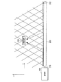
図1は、本発明の一実施形態による位置検出システムの概念を示す図である。
本実施形態による位置検出システムは、ユーザが携帯する移動端末300と、移動端末300と無線通信を行う基地局100と、移動端末300と基地局100との無線通信を中継する漏洩同軸ケーブルであるLCX200とを備える。LCX200の一端は、基地局100に接続された通信端220であり、他端は、LCX200の内部を伝播する電気信号が反射するように構成された反射端210である。
Hereinafter, an embodiment of the present invention will be described with reference to the drawings.
FIG. 1 is a diagram illustrating a concept of a position detection system according to an embodiment of the present invention.
The position detection system according to the present embodiment is a
例えば、移動端末300から出力される信号が、角度θによる2箇所(A点とB点)からLCX200に受波される。A点とB点のうち、基地局100により近いA点からLCX200に受波された直接波が、まず基地局100に到着する。A点とB点のうち、基地局100から離れたB点からLCX200に受波された信号は、反射端210で反射してから、反射波として基地局100に到着する。この二つの経路の到来信号を基地局100が受信し、直接波と反射波の伝搬時間または伝搬時間差により二次元位置の検出を行う。なお、基地局100から信号を送信する場合にも適用可能である。
このように、本実施形態によれば、一本の漏洩同軸ケーブル(LCX200)を用いて移動端末300の二次元位置を検出、算出することが可能である。
For example, a signal output from the
Thus, according to this embodiment, it is possible to detect and calculate the two-dimensional position of the
<第1の実施形態:構成>
図2は、第1の実施形態による位置検出システムの構成を示すブロック図である。本実施形態による位置検出システムは、基地局100−1と、LCX200−1と、移動端末300−1とを備えている。
<First Embodiment: Configuration>
FIG. 2 is a block diagram showing the configuration of the position detection system according to the first embodiment. The position detection system according to the present embodiment includes a base station 100-1, an LCX 200-1, and a mobile terminal 300-1.
基地局100−1は、算出部120−1と、直接波受信部140−1と、反射波受信部150−1と、位置表示地図情報送信部160−1と、表示部170−1と、地図情報記憶部180−1とを備えている。
地図情報記憶部180-1は、LCX200−1の布設状況を、地図情報として予め記憶する。地図情報記憶部180-1が記憶する地図情報の例を、図20に示す。
算出部120−1は、直接波受信部140−1と反射波受信部150−1とが受信する直接波時間情報と反射波時間情報とに基づいて、地図情報記憶部180−1に記憶された地図情報における移動端末300−1の座標位置を示す位置情報を算出する。
The base station 100-1 includes a calculation unit 120-1, a direct wave reception unit 140-1, a reflected wave reception unit 150-1, a position display map information transmission unit 160-1, a display unit 170-1, And a map information storage unit 180-1.
The map information storage unit 180-1 stores in advance the installation status of the LCX 200-1 as map information. An example of the map information stored in the map information storage unit 180-1 is shown in FIG.
The calculation unit 120-1 is stored in the map information storage unit 180-1 based on the direct wave time information and the reflected wave time information received by the direct wave receiving unit 140-1 and the reflected wave receiving unit 150-1. The position information indicating the coordinate position of the mobile terminal 300-1 in the map information is calculated.
位置表示地図情報生成部190−1は、算出部120−1が算出した位置情報に基づいて、地図情報記憶部180-1に記憶された地図情報上の対応する位置に、図21に示すように、現在位置を示す印が表示された地図情報である位置表示地図情報を生成する。ここで、図21には、現在位置を示す印として星印を示すが、どのような印でも良い。なお、位置表示地図情報には、現在位置を印として示すとともに、座標位置の数値情報などを表示するようにしても良い。表示部170−1は、液晶などによるディスプレイであり、位置表示地図情報を表示する。 Based on the position information calculated by the calculation unit 120-1, the position display map information generation unit 190-1 displays the corresponding position on the map information stored in the map information storage unit 180-1 as shown in FIG. In addition, position display map information which is map information on which a mark indicating the current position is displayed is generated. In FIG. 21, a star is shown as a mark indicating the current position, but any mark may be used. In the position display map information, the current position may be indicated as a mark, and numerical information on the coordinate position may be displayed. The display unit 170-1 is a display using liquid crystal or the like, and displays position display map information.
直接波受信部140−1は、LCX200のスロット230−N(Nは任意の整数。例えば、スロット230−1)から角度θで受波される直接波を受信し、反射波受信部150−1は、LCX200−1のスロット230−M(Mは任意の整数。例えば、スロット230−2)から角度θで受波される反射波を受信する。
位置表示地図情報送信部160−1は、位置表示地図情報生成部190−1が生成した位置表示地図情報を、移動端末300−1に送信する。
The direct wave receiving unit 140-1 receives a direct wave received at an angle θ from the slot 230-N (N is an arbitrary integer. For example, the slot 230-1) of the
The position display map information transmission unit 160-1 transmits the position display map information generated by the position display map information generation unit 190-1 to the mobile terminal 300-1.
LCX200−1は、漏洩同軸ケーブルであり、反射端210−1と、通信端220−1と、スロット230−1、スロット230−2、・・・スロット230−Q(Qは任意の整数)とを備えている。漏洩同軸ケーブルは、高周波信号を伝送する同軸ケーブルであり、ケーブル全体がアンテナとして機能するものである。図3に示すように、例えば、漏洩同軸ケーブルは、シース291、外部導体292、絶縁体293、内部導体294の四層で構成されている。そして、一般的な同軸ケーブルの外側の導体部分である外部導体292に複数のスロット(放射孔ともいう)と呼ばれる穴を開けることで電波が入放射され、隣接する複数のスロットは相互に作用して送受信アンテナとして機能する。
LCX 200-1 is a leaky coaxial cable, and includes a reflection end 210-1, a communication end 220-1, a slot 230-1, a slot 230-2,... Slot 230-Q (Q is an arbitrary integer). It has. The leaky coaxial cable is a coaxial cable that transmits a high-frequency signal, and the entire cable functions as an antenna. As shown in FIG. 3, for example, the leaky coaxial cable includes four layers of a
漏洩同軸ケーブル内を伝搬する電波の波長がスロットの大きさよりも十分に長い場合、スロットから放射される電波は微小ダイポールから放射されている電波と等価であり、漏洩同軸ケーブルの構造はケーブルの長手方向に微小ダイポールが放射孔の間隔で連続的に配置された構造となる。一方、スロットから放射される電波の位相は、ケーブル内を伝搬する電波の位相に依存するため、各スロットから放射される電波は位相が異なっている。このため漏洩同軸ケーブルから放射された空間中の電波は、各スロットから放射された位相のずれた電波の重ね合わせとなる。そのため、放射角度により電波の強め合いや弱め合いが発生することにより指向特性を持つ。ここで、漏洩同軸ケーブルの放射孔の間隔P/2(メートル)と漏洩同軸ケーブル内の搬送波の波長λRF(メートル)によって電波の放射角度θmが以下式(2)によって決まる。 If the wavelength of the radio wave propagating in the leaky coaxial cable is sufficiently longer than the slot size, the radio wave radiated from the slot is equivalent to the radio wave radiated from the minute dipole, and the structure of the leaky coaxial cable is the length of the cable. The structure is such that minute dipoles are continuously arranged in the direction at intervals of the radiation holes. On the other hand, since the phase of the radio wave radiated from the slot depends on the phase of the radio wave propagating in the cable, the phase of the radio wave radiated from each slot is different. For this reason, the radio waves in the space radiated from the leaky coaxial cable are superimposed on the radio waves radiated from the slots and out of phase. For this reason, the radio wave has directional characteristics due to radio wave strengthening or weakening depending on the radiation angle. Here, the radiation angle θm of the radio wave is determined by the following equation (2) according to the interval P / 2 (meter) of the radiation hole of the leaky coaxial cable and the wavelength λ RF (meter) of the carrier wave in the leaky coaxial cable.
ここで、放射波を得るためには、式(2)は実数である必要があり、その為には、mは負の整数となる必要がある。εrは漏洩同軸ケーブル内部の絶縁体の比誘電率を表す。すなわち、漏洩同軸ケーブル内を伝搬して外部に漏洩する電磁波は、各スロットからの位相差が2Pnπのときに同一の放射角度θmを有する放射波となる。この条件を満足するPnは、式(2)が実数となる範囲でいくつも存在し、複数の放射モード(m)が存在する事になる。これを、例えばm次モードの放射波といい、m=2n、m=2n+1の関係となる(例えば、以下文献参照。岸本利彦、佐々木伸、LCX通信システム、コロナ社)。すなわち、放射角度θmは、波長(周波数)によって、ケーブルの半径方向を0度として、−90度〜+90度まで変化する。これ以降、m=−1を前提とし、θmを単にθと表記する。なお、式(1)を用いて位置検出を行う為には、式(2)のmを一定にする必要がある。一般の漏洩同軸は、多くのモードの放射波が存在すると複数の放射波同士の干渉により、強度に変動が生ずる。これを避けるために通常の漏洩同軸ケーブルでは、m=−1のみを存在させるように、Pやスロット配列を工夫している(前記参考文献参照。)。本実施形態でも、この従来技術を用いてm=−1の単一モードを使用することとする Here, in order to obtain a radiated wave, Equation (2) needs to be a real number, and for that purpose, m needs to be a negative integer. εr represents the relative dielectric constant of the insulator inside the leaky coaxial cable. That is, the electromagnetic wave propagating through the leaky coaxial cable and leaking outside becomes a radiated wave having the same radiation angle θm when the phase difference from each slot is 2Pnπ. There are a number of Pn satisfying this condition in the range where the expression (2) is a real number, and there are a plurality of radiation modes (m). This is called, for example, an m-order mode radiation wave, and has a relationship of m = 2n and m = 2n + 1 (for example, refer to the following literature: Toshihiko Kishimoto, Shin Sasaki, LCX communication system, Corona). That is, the radiation angle θm varies from −90 degrees to +90 degrees depending on the wavelength (frequency), with the radial direction of the cable being 0 degrees. Hereinafter, assuming that m = −1, θm is simply expressed as θ. In addition, in order to perform position detection using Formula (1), it is necessary to make m of Formula (2) constant. In general leaky coaxial, when there are many modes of radiated waves, the intensity varies due to interference between the radiated waves. In order to avoid this, in a normal leaky coaxial cable, P and the slot arrangement are devised so that only m = −1 exists (see the above-mentioned reference). Also in this embodiment, a single mode of m = −1 is used using this conventional technique.
通信端220−1は、基地局100−1の直接波受信部140−1と反射波受信部150−1と接続され、信号の入出力を行う。LCX200−1には、上述のような放射孔である複数のスロット230(スロット230−1、スロット230−2、スロット230−3、・・・)が備えられている。反射端210−1は、LCX200−1内部を伝搬してきた信号を反射する構成となっている。反射端210−1は、例えば、開放終端となっている。また、例えば、無線信号反射装置を備える構成としても良い。あるいは、終端抵抗を接続しておき、位置検出を行うときのみ終端抵抗を外して開放終端とするように構成しても良い。 The communication terminal 220-1 is connected to the direct wave receiving unit 140-1 and the reflected wave receiving unit 150-1 of the base station 100-1, and inputs and outputs signals. The LCX 200-1 is provided with a plurality of slots 230 (slot 230-1, slot 230-2, slot 230-3,...) That are radiation holes as described above. The reflection end 210-1 is configured to reflect a signal propagating through the LCX 200-1. The reflection end 210-1 is, for example, an open end. For example, it is good also as a structure provided with a radio signal reflecting device. Alternatively, a termination resistor may be connected, and the termination resistor may be removed and open termination only when position detection is performed.
移動端末300−1は、例えば、ユーザが携帯する端末であり、本実施形態では、信号送信部340−1と、無線通信部350−1と、位置表示地図情報受信部360−1と、表示部370−1とを備えている。
信号送信部340−1は、LCX200−1が移動端末300−1の位置を検出するための電気信号を空間中に出力する。ここで、電気信号は、基地局100−1が時間間隔を計測可能な情報であり、信号送信部340−1は、時間情報を識別可能な信号を送出する。電気信号を複数回送信する場合や常時送信し続ける場合には、直接波と反射波とのそれぞれが示す時間情報を比較することで、同一の電気信号によるものであるか否かを識別することができる。また、直接波と反射波が同一の電気信号によるものであるか否かは、他に、例えば、電気信号として出力する情報パケットのヘッダに識別情報を含め、基地局100−1はこの識別情報を比較して対応関係を判定しても良い。
The mobile terminal 300-1 is, for example, a terminal carried by the user. In this embodiment, the mobile terminal 300-1 includes a signal transmission unit 340-1, a wireless communication unit 350-1, a position display map information reception unit 360-1, and a display. Part 370-1.
The signal transmission unit 340-1 outputs an electric signal for detecting the position of the mobile terminal 300-1 in the space by the LCX 200-1. Here, the electrical signal is information that allows the base station 100-1 to measure the time interval, and the signal transmission unit 340-1 transmits a signal that can identify the time information. When transmitting electrical signals multiple times or continuously transmitting them, it is possible to identify whether they are due to the same electrical signal by comparing the time information indicated by the direct wave and the reflected wave. Can do. Further, whether the direct wave and the reflected wave are due to the same electric signal, for example, includes identification information in the header of an information packet output as an electric signal, and the base station 100-1 determines this identification information. May be compared to determine the correspondence.
無線通信部350−1は、信号送信部340−1とは異なる周波数帯域によって、基地局100−1と無線通信を行う。無線通信部350−1は、例えば、携帯電話通信や、ノートPC(Personal Computer)やPDA(Personal Digital Assistant)などのなどの移動可能な端末との無線通信を行う。
位置表示地図情報受信部360−1は、位置表示地図情報送信部160−1から送信される位置表示地図情報を受信する。表示部370−1は、液晶などによるディスプレイであり、位置表示地図情報受信部360−1が受信する位置表示地図情報を表示する。
The radio communication unit 350-1 performs radio communication with the base station 100-1 using a frequency band different from that of the signal transmission unit 340-1. For example, the wireless communication unit 350-1 performs wireless communication with a mobile terminal such as mobile phone communication or a notebook PC (Personal Computer) or PDA (Personal Digital Assistant).
The position display map information receiving unit 360-1 receives the position display map information transmitted from the position display map information transmitting unit 160-1. The display unit 370-1 is a display using liquid crystal or the like, and displays position display map information received by the position display map information receiving unit 360-1.
次に、本実施形態による位置検出の動作原理について説明する。本実施形態による位置検出は、信号が特定の点から別の点に到達する時間に基づいて距離を決定するTOA(Time Of Arrival)方式に基づく。
図4に示すように、移動端末300から空間中に出力され、LCX200に受波される信号は、移動端末300がA地点とB地点にある場合、同時に通信端220に到着する。すなわち、信号が基地局100に到着する到着時間が等しい移動端末300の場所は、空間中の信号伝搬時間と、LCX200中の信号伝搬時間との和で表されるために、基地局100に信号が同時に到着する空間中の場所は図4に示すようなラインL(L1、L2、L3)を形成する。つまり、直接波だけの到着時間を計測しても、位置の特定はできない。
Next, the operation principle of position detection according to this embodiment will be described. The position detection according to the present embodiment is based on a TOA (Time Of Arrival) method in which a distance is determined based on a time at which a signal reaches another point from a specific point.
As shown in FIG. 4, the signal output from the
そこで、LCX200の反射端210で反射する反射波をも計測に用いる。すなわち、図5に示すように、LCX200が敷設された延びる方向をX軸として、LCX200と垂直方向をY軸とし、X方向の位置xとY方向の位置yとの値によって移動端末300の位置を算出する場合に、xを直接波の到着時間と反射波との到着時間の差として算出することができ、また、yを移動端末300から信号が出力されてから基地局100が直接波と反射波との信号を受信するまでの時間の和として算出することができる。
Therefore, the reflected wave reflected by the reflection end 210 of the
すなわち、図6に示すように、直接波と反射波との到着間隔が短ければ短いほど、移動端末300の位置が反射端210に近いことを示す。直接波がLCX200に受波され、基地局100に到着した後に、信号が反射端210で反射し、反射波が基地局100に到着するまでに伝搬した距離が短いといえるからである。
また、図7に示すように、移動端末300が信号を出力してから直接波が基地局100に到達するまでの時間が長ければ長いほど、移動端末300がLCX200から離れていることを示す。以上を踏まえ、図8のように各値を定義すると、以下式(3)が成り立つ。
That is, as shown in FIG. 6, the shorter the arrival interval between the direct wave and the reflected wave, the closer the position of the
Further, as illustrated in FIG. 7, the longer the time from when the
これを、以下式(4)のように解くと、以下式(1)が導かれる。 When this is solved as in the following formula (4), the following formula (1) is derived.
このように、上述の式(1)によれば、直接波の到着時間(t1)と、反射波の到着時間(t2)とをパラメータとして与えることで、移動端末300の位置を算出することができる。算出部120は、上述の式(1)によって移動端末300の位置を算出する。
Thus, according to equation (1) described above, by giving the direct wave arrival time (t 1), the arrival time of the reflected wave and a (t 2) as a parameter, to calculate the position of the
<第1の実施形態:動作>
次に、図9を参照して、本発明による位置検出システムが、移動端末300−1の位置情報を算出する動作例を説明する。
上述のように、地図情報記憶部180−1は、予め図20に示すような地図情報を記憶する。
まず、移動端末300−1の信号送信部340−1は、信号を空間中に出力する(ステップS10)。そして、信号は、スロット230−1に受波され、LCX200−1内を直接波として伝搬する。(ステップS20)。基地局100−1の直接波受信部140−1は、直接波を受信すると、受信時間を直接波受信時間情報として記憶する。また、スロット230−2に受波された信号は、LCX200−1内を伝搬し、反射端210−1で反射し、反射波として基地局100−1の反射波受信部150−1に受信される(ステップS30)。
<First Embodiment: Operation>
Next, with reference to FIG. 9, an operation example in which the position detection system according to the present invention calculates position information of the mobile terminal 300-1 will be described.
As described above, the map information storage unit 180-1 stores map information as shown in FIG. 20 in advance.
First, the signal transmission part 340-1 of the mobile terminal 300-1 outputs a signal in space (step S10). The signal is received by the slot 230-1 and propagates as a direct wave in the LCX 200-1. (Step S20). When receiving the direct wave, the direct wave receiving unit 140-1 of the base station 100-1 stores the reception time as the direct wave reception time information. The signal received in the slot 230-2 propagates in the LCX 200-1, is reflected by the reflection end 210-1, and is received as a reflected wave by the reflected wave receiving unit 150-1 of the base station 100-1. (Step S30).
基地局100−1の反射波受信部150−1は、反射波を受信すると、受信時間を反射波受信時間情報として記憶する。基地局100−1の算出部120−1は、時間情報を受信すると、上述の式(1)を用いて、推定X座標値と推定Y座標値との値を位置情報として算出する(ステップS40)。そして、位置表示地図情報生成部190−1は、地図情報記憶部180−1に記憶された地図情報を読み出し、算出部120−1が算出した位置情報に対応する地図情報上の位置に、星印を付加した位置表示地図情報を生成する。位置表示地図情報送信部160−1は、位置表示地図情報生成部190−1が生成した位置表示地図情報を、移動端末300−1に送信する(ステップS50)。位置表示地図情報受信部360−1が位置表示地図情報を受信すると、表示部370−1が、受信した位置表示地図情報を表示させる。 When receiving the reflected wave, the reflected wave receiving unit 150-1 of the base station 100-1 stores the reception time as reflected wave reception time information. Upon receiving the time information, the calculation unit 120-1 of the base station 100-1 calculates the value of the estimated X coordinate value and the estimated Y coordinate value as position information using the above-described equation (1) (step S40). ). And the position display map information generation part 190-1 reads the map information memorize | stored in the map information storage part 180-1, and it is a star on the position on the map information corresponding to the position information which the calculation part 120-1 calculated. The position display map information with the mark added is generated. The position display map information transmission unit 160-1 transmits the position display map information generated by the position display map information generation unit 190-1 to the mobile terminal 300-1 (step S50). When the position display map information receiving unit 360-1 receives the position display map information, the display unit 370-1 displays the received position display map information.
また、位置表示地図情報生成部190−1が生成した位置表示地図情報は、基地局100−1の表示部170−1に表示させても良いし、外部のサーバへ送信する構成としても良い。
以上説明したように、本実施形態によれば、移動端末300−1は信号送信部340−1を備えるのみで位置検出を行うことができ、移動端末300−1は安価な端末で足り、また、省電力に位置検出を行うことができる。
このような位置検出システムは、例えば、ビルの内部や地下などで作業を行う消防隊員に移動端末300−1を携帯させ、地上の消防隊隊長などが消防隊員の位置情報を把握する場合に特に有効である。
Further, the position display map information generated by the position display map information generation unit 190-1 may be displayed on the display unit 170-1 of the base station 100-1, or may be transmitted to an external server.
As described above, according to the present embodiment, the mobile terminal 300-1 can perform position detection only by including the signal transmission unit 340-1, and the mobile terminal 300-1 may be an inexpensive terminal. The position detection can be performed with low power consumption.
Such a position detection system is particularly used when, for example, a fire brigade member who performs work in a building or underground, carries the mobile terminal 300-1, and the fire brigade commander on the ground grasps the location information of the fire brigade member. It is valid.
<第2の実施形態:構成>
第1の実施形態において移動端末300−1の信号送信部340−1が出力した位置検出のための信号は、基地局100が出力するように構成しても良い。図10は、第2の実施形態による位置検出システムの概念を示す図である。基地局100から通信端220を介してLCX200に送信された信号は、LCX200の線路にそって伝搬し、この進行方向に対して特定の角度θで放射され、直接波として移動端末300に到着する。さらに、LCX200を伝搬する信号は、反射端210で反射し、直接波と同様に進行方向に対して決まった角度θで放射され、反射波として移動端末300に到着する。この二つの経路の到来信号を移動端末300が受信し、直接波と反射波の伝搬時間または伝搬時間差により二次元位置の検出を行う。なお、移動端末300から信号を送信する場合にも適用可能である。
<Second Embodiment: Configuration>
The
第2の実施形態による位置検出システムは、第1の実施形態と同様の構成をしており、同様の構成・処理については説明を省略する。以下、第2の実施形態に特有の構成・処理について説明する。図11は、本実施形態による位置検出システムの構成を示すブロック図である。本実施形態による位置検出システムは、基地局100−2と、LCX200−2と、移動端末300−2とを備えている。 The position detection system according to the second embodiment has the same configuration as that of the first embodiment, and the description of the same configuration and processing is omitted. Hereinafter, the configuration and processing unique to the second embodiment will be described. FIG. 11 is a block diagram showing the configuration of the position detection system according to the present embodiment. The position detection system according to the present embodiment includes a base station 100-2, an LCX 200-2, and a mobile terminal 300-2.
基地局100−2は、LCX200−2を介して移動端末300−2と通信を行う通信基地局であり、信号送信部130−2と、地図情報記憶部180−2とを備えている。信号送信部130−2は、LCX200−2の通信端220−2に接続され、通信端220−2と信号の入出力を行う。また、信号送信部130−2は、位置情報を検出するための信号とともに、地図情報記憶部180−2に記憶された地図情報を移動端末300−2に送信する。 The base station 100-2 is a communication base station that communicates with the mobile terminal 300-2 via the LCX 200-2, and includes a signal transmission unit 130-2 and a map information storage unit 180-2. The signal transmission unit 130-2 is connected to the communication end 220-2 of the LCX 200-2 and inputs / outputs signals with the communication end 220-2. Moreover, the signal transmission part 130-2 transmits the map information memorize | stored in the map information storage part 180-2 with the signal for detecting a positional information to the mobile terminal 300-2.
移動端末300−2は、ユーザに携帯される端末であり、直接波受信部320−2と、反射波受信部330−2と、無線通信部350−2と、表示部370−2と、算出部380−2と、位置表示地図情報生成部390−2とを備えている。
算出部380−2は、直接波受信部320−2が直接波を受信した時間を示す直接波時間情報と反射波受信部330−2が反射波を受信した時間を示す反射波時間情報とに基づいて、移動端末300−2の位置を示す位置情報を算出する。
The mobile terminal 300-2 is a terminal carried by the user, and includes a direct wave receiving unit 320-2, a reflected wave receiving unit 330-2, a wireless communication unit 350-2, a display unit 370-2, and a calculation. Unit 380-2 and a position display map information generation unit 390-2.
The calculation unit 380-2 includes direct wave time information indicating the time when the direct wave receiving unit 320-2 receives the direct wave and reflected wave time information indicating the time when the reflected wave receiving unit 330-2 receives the reflected wave. Based on this, position information indicating the position of the mobile terminal 300-2 is calculated.
<第2の実施形態:動作>
次に、図12を参照して、本発明による位置検出システムが、移動端末300−2の位置情報を算出する動作例を説明する。
まず、基地局100−2の信号送信部130−2は、地図情報記憶部180−2に記憶された地図情報と、位置を検出するための信号とを通信端220−2に出力する(ステップS110)。ここで、信号送信部130−2は、さらに、座標位置情報から地図情報上の位置を検出するための計算アルゴリズムを送信することとしても良い。そして、信号送信部130から出力された情報は、LCX200−2内を伝搬する。そして、角度θによってスロット231−1から直接波が放射される(ステップS120)。移動端末300−2の直接波受信部320−2が直接波を受信すると、受信時間を直接波受信時間情報として記憶する。そして、LCX200−2内を伝搬する信号は、反射端210−2で反射し、さらに角度θによってスロット231−2から反射波が放射される(ステップS130)。
<Second Embodiment: Operation>
Next, with reference to FIG. 12, an operation example in which the position detection system according to the present invention calculates position information of the mobile terminal 300-2 will be described.
First, the signal transmission unit 130-2 of the base station 100-2 outputs the map information stored in the map information storage unit 180-2 and a signal for detecting the position to the communication terminal 220-2 (step). S110). Here, the signal transmission unit 130-2 may further transmit a calculation algorithm for detecting a position on the map information from the coordinate position information. And the information output from the signal transmission part 130 propagates in LCX200-2. Then, a direct wave is radiated from the slot 231-1 at an angle θ (step S120). When the direct wave receiver 320-2 of the mobile terminal 300-2 receives a direct wave, the reception time is stored as direct wave reception time information. The signal propagating in the LCX 200-2 is reflected by the reflection end 210-2, and a reflected wave is radiated from the slot 231-2 at an angle θ (step S130).
そして、移動端末300−2の反射波受信部330−2が反射波を受信すると、受信時間を反射波受信時間情報として記憶する。そして、算出部380−2は、直接波受信時間情報と反射波受信時間情報との時間情報に基づいて、上述の式(1)を用いて、推定X座標値と推定Y座標値との値を位置情報として算出する(ステップS140)。そして、位置表示地図情報生成部390−2は、位置を検出するための信号とともに信号送信部130−2から送信された地図情報を読み出し、算出部120−1が算出した位置情報に対応する地図情報上の位置に、星印を付加した位置表示地図情報を生成する。
位置表示地図情報生成部390−2が生成した位置表示地図情報は、移動端末300−2の表示部370−2に表示される。
Then, when the reflected wave reception unit 330-2 of the mobile terminal 300-2 receives the reflected wave, the reception time is stored as reflected wave reception time information. And the calculation part 380-2 uses the above-mentioned Formula (1) based on the time information of direct wave reception time information and reflected wave reception time information, and the value of an estimated X coordinate value and an estimated Y coordinate value. Is calculated as position information (step S140). And the position display map information generation part 390-2 reads the map information transmitted from the signal transmission part 130-2 with the signal for detecting a position, and the map corresponding to the position information which the calculation part 120-1 calculated The position display map information with the star added to the position on the information is generated.
The position display map information generated by the position display map information generation unit 390-2 is displayed on the display unit 370-2 of the mobile terminal 300-2.
このように、第2の実施形態によれば、基地局100−2が電気信号を出力し、移動端末300−2は、受信する電気信号の直接波と反射波との受信時間に基づいて位置情報を算出して位置表示地図情報を生成するので、基地局100−1が算出した位置情報を移動端末300−1が受信する第1の実施形態に比べて、時間の誤差が少なくなる。
このような位置検出システムは、例えば、ビルの内部や地下などで、消防隊員が移動端末300−2を携帯し、自分の位置情報を確認する場合に特に有効である。
Thus, according to the second embodiment, the base station 100-2 outputs an electrical signal, and the mobile terminal 300-2 is positioned based on the reception time of the direct wave and the reflected wave of the received electrical signal. Since the position display map information is generated by calculating the information, the time error is smaller than in the first embodiment in which the mobile terminal 300-1 receives the position information calculated by the base station 100-1.
Such a position detection system is particularly effective when, for example, a fire brigade carries the mobile terminal 300-2 and confirms his / her position information inside a building or underground.
<第3の実施形態:構成>
第3の実施形態は、基地局100−3が出力する電気信号を、移動端末300−3が受信し、受信した時間情報を基地局100−3に送信して、基地局100−3が位置情報の算出を行う。
第3の実施形態による位置検出システムは、第2の実施形態と同様の構成をしており、同様の構成・処理については説明を省略する。以下、第3の実施形態に特有の構成・処理について説明する。図13は、本実施形態による位置検出システムの構成を示すブロック図である。本実施形態による位置検出システムは、基地局100−3と、LCX200−3と、移動端末300−3とを備えている。
<Third Embodiment: Configuration>
In the third embodiment, the mobile terminal 300-3 receives an electrical signal output from the base station 100-3, transmits the received time information to the base station 100-3, and the base station 100-3 Information is calculated.
The position detection system according to the third embodiment has the same configuration as that of the second embodiment, and the description of the same configuration and processing is omitted. Hereinafter, the configuration and processing unique to the third embodiment will be described. FIG. 13 is a block diagram showing the configuration of the position detection system according to this embodiment. The position detection system according to the present embodiment includes a base station 100-3, an LCX 200-3, and a mobile terminal 300-3.
基地局100−3は、LCX200−3を介して移動端末300−3と通信を行う通信基地局であり、時間情報受信部110−3と、算出部120−3と、信号送信部130−3と、位置表示地図情報送信部160−3と、地図情報記憶部180−3とを備えている。時間情報受信部110−3は、移動端末300−3から送信される時間情報、すなわち移動端末300がLCX200−3から直接波を受信する直接波時間情報と反射波を受信する反射波時間情報とを含む時間情報を受信する。
The base station 100-3 is a communication base station that communicates with the mobile terminal 300-3 via the LCX 200-3, and includes a time information reception unit 110-3, a calculation unit 120-3, and a signal transmission unit 130-3. And a position display map information transmission unit 160-3 and a map information storage unit 180-3. The time information receiving unit 110-3 includes time information transmitted from the mobile terminal 300-3, that is, direct wave time information for the
算出部120−3は、移動端末300−3から時間情報受信部110−3が受信する直接波時間情報と反射波時間情報とに基づいて、移動端末300−3の位置を示す位置情報を算出する。
信号送信部130−3は、LCX200−3の通信端220−3に接続され、通信端220−3と信号の入出力を行う。
The calculation unit 120-3 calculates position information indicating the position of the mobile terminal 300-3 based on the direct wave time information and the reflected wave time information received by the time information reception unit 110-3 from the mobile terminal 300-3. To do.
The signal transmission unit 130-3 is connected to the communication end 220-3 of the LCX 200-3 and inputs / outputs signals with the communication end 220-3.
移動端末300−3は、例えば、ユーザに携帯される端末であり、直接波受信部320−3と、反射波受信部330−3と、時間情報送信部310−3と、無線通信部350−3と、位置表示地図情報受信部360−3と、表示部370−3とを備えている
直接波受信部320−3は、LCX200−3のスロット232(例えば、スロット232−1)から角度θで放射される直接波を受信し、反射波受信部330−3は、LCX200−3のスロット232(例えば、スロット232−2)から角度θで放射される反射波を受信する。時間情報送信部310−3は、直接波受信部320−3が直接波を受信した時間情報である直接波時間情報と、反射波受信部330−3が反射波を受信した時間情報である反射波時間情報とを含む時間情報を、基地局100−3に送信する。
The mobile terminal 300-3 is, for example, a terminal carried by the user, and includes a direct wave receiving unit 320-3, a reflected wave receiving unit 330-3, a time information transmitting unit 310-3, and a wireless communication unit 350-. 3, a position display map information receiving unit 360-3, and a display unit 370-3. The direct wave receiving unit 320-3 has an angle θ from the slot 232 (for example, the slot 232-1) of the LCX 200-3. The reflected wave receiving unit 330-3 receives the reflected wave radiated at an angle θ from the slot 232 (for example, the slot 232-2) of the LCX 200-3. The time information transmitting unit 310-3 includes direct wave time information that is time information when the direct wave receiving unit 320-3 receives a direct wave, and reflection that is time information when the reflected wave receiving unit 330-3 receives a reflected wave. Time information including wave time information is transmitted to the base station 100-3.
<第3の実施形態:動作>
次に、図14を参照して、本発明による位置検出システムが、移動端末300の位置情報を算出する動作例を説明する。
まず、基地局100−3の信号送信部130−3は、信号を通信端220−3に出力する(ステップS210)。そして、信号は、LCX200−3内を伝搬する。そして、角度θによってスロット232−1から直接波が放射される(ステップS220)。移動端末300−3の直接波受信部320−3が直接波を受信すると、受信時間を直接波受信時間情報として記憶する。そして、LCX200−3内を伝搬する信号は、反射端210−3で反射し、さらに角度θによってスロット232−2から反射波が放射される(ステップS230)。
<Third Embodiment: Operation>
Next, with reference to FIG. 14, an example of an operation in which the position detection system according to the present invention calculates position information of the
First, the signal transmission unit 130-3 of the base station 100-3 outputs a signal to the communication terminal 220-3 (step S210). Then, the signal propagates through the LCX 200-3. Then, a direct wave is radiated from the slot 232-1 at the angle θ (step S220). When the direct wave receiving unit 320-3 of the mobile terminal 300-3 receives a direct wave, the reception time is stored as direct wave reception time information. The signal propagating in the LCX 200-3 is reflected by the reflection end 210-3, and a reflected wave is emitted from the slot 232-2 at an angle θ (step S230).
そして、移動端末300−3の反射波受信部330−3が反射波を受信すると、受信時間を反射波受信時間情報として記憶する。そして、時間情報送信部310−3は、直接波受信時間情報と反射波受信時間情報との時間情報を、基地局100−3に送信する(ステップS240)。基地局100−3の時間情報受信部110−3は、時間情報を受信すると、上述の式(1)を用いて、推定X座標値と推定Y座標値との値を位置情報として算出する(ステップS250)。 Then, when the reflected wave receiving unit 330-3 of the mobile terminal 300-3 receives the reflected wave, the reception time is stored as reflected wave reception time information. And the time information transmission part 310-3 transmits the time information of direct wave reception time information and reflected wave reception time information to the base station 100-3 (step S240). When receiving the time information, the time information receiving unit 110-3 of the base station 100-3 calculates the value of the estimated X coordinate value and the estimated Y coordinate value as position information using the above-described equation (1) ( Step S250).
そして、位置表示地図情報生成部190−3は、地図情報記憶部180−3に記憶された地図情報を読み出し、算出部120−1が算出した位置情報に対応する地図情報上の位置に、星印を付加した位置表示地図情報を生成する。位置表示地図情報送信部160−3は、位置表示地図情報生成部190−3が生成した位置表示地図情報を、移動端末300−3に送信する(ステップS260)。移動端末300−3の位置表示地図情報受信部360−3が、位置表示地図情報を受信すると、位置表示地図情報が表示部370−3に表示される。
また、位置表示地図情報生成部190−3が生成した位置表示地図情報は、例えば、基地局100−3に表示部を設けて表示しても良いし、外部のサーバへ送信する構成としても良い。
And the position display map information generation part 190-3 reads the map information memorize | stored in the map information storage part 180-3, and a star on the position on the map information corresponding to the position information which the calculation part 120-1 calculated. The position display map information with the mark added is generated. The position display map information transmission unit 160-3 transmits the position display map information generated by the position display map information generation unit 190-3 to the mobile terminal 300-3 (step S260). When the position display map information receiving unit 360-3 of the mobile terminal 300-3 receives the position display map information, the position display map information is displayed on the display unit 370-3.
Further, the position display map information generated by the position display map information generation unit 190-3 may be displayed with a display unit provided in the base station 100-3, for example, or may be transmitted to an external server. .
以上説明したように、本実施形態によれば、通信端220−3からLCX200−3を介して空間中に伝搬した信号である直接波が移動端末300−3に到着する到着時間と、同信号がLCX200−3の通信端220−3の他端である反射端210−3で反射してからの反射波が移動端末300−3に到着する到着時間をパラメータとすることで、一本の漏洩同軸ケーブルを用いて、単一周波数によって、移動端末300−3の二次元位置を検出、算出することが可能である。 As described above, according to the present embodiment, the arrival time when the direct wave that is a signal propagated in the space from the communication end 220-3 via the LCX 200-3 arrives at the mobile terminal 300-3, and the same signal By using, as a parameter, the arrival time when the reflected wave arrives at the mobile terminal 300-3 after being reflected by the reflection end 210-3 which is the other end of the communication end 220-3 of the LCX 200-3 It is possible to detect and calculate the two-dimensional position of the mobile terminal 300-3 by a single frequency using a coaxial cable.
<他の実施形態>
なお、図15に示すように、上述の反射端210は、サーキュレータ211と帯域フィルタ212と吸収抵抗213とによって構成しても良い。すなわち、LCX200の終端をサーキュレータ211の第1の端子に接続し、サーキュレータ211の第2の端子を、帯域フィルタ212と吸収抵抗213とに接続する。帯域フィルタ212の他端は、サーキュレータ211の第3の端子に接続する。ここで、帯域フィルタ212は、位置検出のための信号のみを通過させるように予め設定する。
このように構成すると、反射端210は、位置検出のための信号のみを反射するようになり、例えば、LCX200を、携帯電話の通信のためのアンテナとして併用しながら、位置検出を行うことができる。
<Other embodiments>
As shown in FIG. 15, the
If comprised in this way, the
なお、図16に示すように、本発明による位置検出は、地下街等、曲がりくねった道路においてLCX200を敷設する場合にも、適用が可能である。
As shown in FIG. 16, the position detection according to the present invention can also be applied to the case where the
<本発明の実施例>
図17に、本発明の位置検出原理よる位置検出実験を行った環境を示す。図中の黒い点が測定点であり、図の左下(XとYの交点)が原点となるように二次元座標を設定し、図の横方向がX軸、縦方向がY軸となるようにした。LCXは、長さが5mであり、床から1.4mの高さになるように設置し、移動端末の受信アンテナに無指向性のアンテナを用い、三脚を用いて、常にLCXと同じ高さになるようにした。2.4GHz帯の微弱電波を用いて、通信端と移動端末間のインパルス応答を測定した。
<Example of the present invention>
FIG. 17 shows an environment in which a position detection experiment based on the position detection principle of the present invention was performed. Two-dimensional coordinates are set so that the black point in the figure is the measurement point, and the lower left of the figure (the intersection of X and Y) is the origin, so that the horizontal direction in the figure is the X axis and the vertical direction is the Y axis I made it. The LCX is 5m long and 1.4m above the floor, uses a non-directional antenna as the receiving antenna of the mobile terminal, and always uses the tripod and is always the same height as the LCX. I tried to become. The impulse response between the communication end and the mobile terminal was measured using a weak 2.4 GHz band radio wave.
図18は、ネットワークアナライザの本実験でのインパルス応答の測定例を示す波形図である。図中の直接波または反射波の振幅比が最大となった時の時間t1およびt2をそれぞれの到着時間とする。
このような実験において、無指向性のアンテナで直接波の到着時間t1と直接波と反射波の到着時間差t2を測定した。t1、t2を式(1)に代入し、測定地点ごとの推定位置を計算した。図19に算出結果の誤差の分布を示す。一箇所の測定点においてそれぞれ16回平均のインパルス応答の観測から得られたt1とt2によって、およそ0.25m以下の位置検出誤差が得られた。このように、直接波の到着時間と反射波の到着時間の二つの数式を連立させることで、直接波と反射波のそれぞれの電波の放射範囲が重なるエリアで、位置検出が精度良く可能であることが確認できた。ここでは、LCXの中央に近いほど、精度の高い結果が得られた。
FIG. 18 is a waveform diagram showing a measurement example of an impulse response in this experiment of the network analyzer. The times t 1 and t 2 when the amplitude ratio of the direct wave or the reflected wave in the figure becomes the maximum are taken as the arrival times.
In such an experiment, the arrival time t 1 of the direct wave and the arrival time difference t 2 of the direct wave and the reflected wave were measured with an omnidirectional antenna. t 1 and t 2 were substituted into Equation (1), and the estimated position for each measurement point was calculated. FIG. 19 shows an error distribution of the calculation result. A position detection error of about 0.25 m or less was obtained by t 1 and t 2 obtained from observation of the average impulse response 16 times at each measurement point. In this way, by combining the two mathematical formulas of the arrival time of the direct wave and the arrival time of the reflected wave, position detection can be performed with high accuracy in an area where the radiation ranges of the direct wave and the reflected wave overlap. I was able to confirm. Here, the closer to the center of the LCX, the higher the accuracy of the result.
このように、一本のLCXを用いて、単一周波数を用いて移動体端末の二次元位置を検出する方式について、位置検出実験にて誤差分散の観測を行い、25cm以下の位置検出誤差を実現できることが分かった。 In this way, for a method of detecting a two-dimensional position of a mobile terminal using a single frequency using a single LCX, error dispersion is observed in a position detection experiment, and a position detection error of 25 cm or less is detected. It turns out that it can be realized.
なお、本発明における処理部の機能を実現するためのプログラムをコンピュータ読み取り可能な記録媒体に記録して、この記録媒体に記録されたプログラムをコンピュータシステムに読み込ませ、実行することにより位置検出を行ってもよい。なお、ここでいう「コンピュータシステム」とは、OSや周辺機器等のハードウェアを含むものとする。また、「コンピュータシステム」は、ホームページ提供環境(あるいは表示環境)を備えたWWWシステムも含むものとする。また、「コンピュータ読み取り可能な記録媒体」とは、フレキシブルディスク、光磁気ディスク、ROM、CD−ROM等の可搬媒体、コンピュータシステムに内蔵されるハードディスク等の記憶装置のことをいう。さらに「コンピュータ読み取り可能な記録媒体」とは、インターネット等のネットワークや電話回線等の通信回線を介してプログラムが送信された場合のサーバやクライアントとなるコンピュータシステム内部の揮発性メモリ(RAM)のように、一定時間プログラムを保持しているものも含むものとする。 It should be noted that a program for realizing the function of the processing unit in the present invention is recorded on a computer-readable recording medium, and the program recorded on the recording medium is read into a computer system and executed for position detection. May be. Here, the “computer system” includes an OS and hardware such as peripheral devices. The “computer system” includes a WWW system having a homepage providing environment (or display environment). The “computer-readable recording medium” refers to a storage device such as a flexible medium, a magneto-optical disk, a portable medium such as a ROM and a CD-ROM, and a hard disk incorporated in a computer system. Further, the “computer-readable recording medium” refers to a volatile memory (RAM) in a computer system that becomes a server or a client when a program is transmitted via a network such as the Internet or a communication line such as a telephone line. In addition, those holding programs for a certain period of time are also included.
また、上記プログラムは、このプログラムを記憶装置等に格納したコンピュータシステムから、伝送媒体を介して、あるいは、伝送媒体中の伝送波により他のコンピュータシステムに伝送されてもよい。ここで、プログラムを伝送する「伝送媒体」は、インターネット等のネットワーク(通信網)や電話回線等の通信回線(通信線)のように情報を伝送する機能を有する媒体のことをいう。また、上記プログラムは、前述した機能の一部を実現するためのものであっても良い。さらに、前述した機能をコンピュータシステムにすでに記録されているプログラムとの組み合わせで実現できるもの、いわゆる差分ファイル(差分プログラム)であっても良い。 The program may be transmitted from a computer system storing the program in a storage device or the like to another computer system via a transmission medium or by a transmission wave in the transmission medium. Here, the “transmission medium” for transmitting the program refers to a medium having a function of transmitting information, such as a network (communication network) such as the Internet or a communication line (communication line) such as a telephone line. The program may be for realizing a part of the functions described above. Furthermore, what can implement | achieve the function mentioned above in combination with the program already recorded on the computer system, what is called a difference file (difference program) may be sufficient.
100 基地局
110 時間情報受信部
120 算出部
130 信号送信部
140 直接波受信部
150 反射波受信部
160 位置表示地図情報送信部
170 表示部
180 地図情報記憶部
190 位置表示地図情報生成部
200 LCX
210 反射端
211 サーキュレータ
212 帯域フィルタ
213 吸収抵抗
220 通信端
230 スロット
291 シース
292 外部導体
293 絶縁体
294 内部導体
300 移動端末
310 時間情報送信部
320 直接波受信部
330 反射波受信部
340 信号送信部
350 無線通信部
360 位置表示地図情報受信部
370 表示部
380 算出部
390 位置表示地図情報生成部
DESCRIPTION OF
210 Reflecting
Claims (8)
前記漏洩同軸ケーブルは、
前記基地局に電気信号を出力するように前記基地局に接続された終端である通信端と、 自ケーブル内部を伝播する電気信号が反射するように構成された他端であり、予め定められた前記電気信号の周波数帯域のみを反射させるための帯域フィルタを備える反射端と、を備え、
前記移動端末は、
前記漏洩同軸ケーブルに前記電気信号を送信する信号送信手段を備え、
前記基地局は、
前記移動端末から送信され前記漏洩同軸ケーブルが受波した電気信号であって、前記反射端で反射せずに前記漏洩同軸ケーブルから前記通信端に入力される電気信号である直接波を受信する直接波受信手段と、
前記漏洩同軸ケーブルの前記反射端に反射した後に前記通信端に入力される電気信号である反射波を受信する反射波受信手段と、
前記直接波受信手段が前記直接波を受信した時間を示す直接波受信時間情報と、前記反射波受信手段が前記反射波を受信した時間を示す反射波受信時間情報とに基づいて、前記移動端末の位置情報を算出する算出手段と、を備える
ことを特徴とする位置検出システム。 A position detection system comprising a mobile terminal capable of wireless communication and a base station that performs wireless communication with the mobile terminal using a leaky coaxial cable as an antenna,
The leaky coaxial cable is
A communication end that is a terminal connected to the base station so as to output an electric signal to the base station, and an other end that is configured to reflect an electric signal propagating through the own cable. A reflection end comprising a bandpass filter for reflecting only the frequency band of the electrical signal,
The mobile terminal
Comprising signal transmission means for transmitting the electrical signal to the leaky coaxial cable;
The base station
An electric signal transmitted from the mobile terminal and received by the leaky coaxial cable, and received directly from the leaky coaxial cable to the communication end without being reflected by the reflection end. Wave receiving means;
Reflected wave receiving means for receiving a reflected wave that is an electric signal input to the communication end after being reflected by the reflection end of the leaky coaxial cable;
Based on the direct wave reception time information indicating the time when the direct wave receiving means receives the direct wave and the reflected wave reception time information indicating the time when the reflected wave receiving means receives the reflected wave, the mobile terminal A position detecting system comprising: a calculating means for calculating the position information of the position.
前記漏洩同軸ケーブルは、
前記基地局から電気信号を入力されるように前記基地局に接続された終端である通信端と、
自ケーブル内部を伝播する電気信号が反射するように構成された他端であり、予め定められた前記電気信号の周波数帯域のみを反射させるための帯域フィルタを備える反射端と、を備え、
前記移動端末は、
前記基地局から前記通信端を介して前記漏洩同軸ケーブルに出力された電気信号によって、前記反射端で反射する前に前記漏洩同軸ケーブルから空間中に放射される直接波を受信する直接波受信手段と、
前記漏洩同軸ケーブルの前記反射端に反射した後の電気信号によって前記漏洩同軸ケーブルから空間中に放射される反射波を受信する反射波受信手段と、
前記直接波受信手段が前記直接波を受信した時間を示す直接波受信時間情報と、前記反射波受信手段が前記反射波を受信した時間を示す反射波受信時間情報とに基づいて、自端末の位置情報を算出する算出手段と、を備え、
前記基地局は、
前記漏洩同軸ケーブルの前記通信端に接続され、当該漏洩同軸ケーブルを介して前記移動端末に前記電気信号を送信する信号送信手段と、を備える
ことを特徴とする位置検出システム。 A position detection system comprising a mobile terminal capable of wireless communication and a base station that performs wireless communication with the mobile terminal using a leaky coaxial cable as an antenna,
The leaky coaxial cable is
A communication end that is a terminal connected to the base station so that an electric signal is input from the base station;
A second end configured to reflect an electric signal propagating inside the own cable, and a reflection end including a bandpass filter for reflecting only a predetermined frequency band of the electric signal, and
The mobile terminal
Direct wave receiving means for receiving a direct wave radiated from the leaky coaxial cable into the space before being reflected at the reflection end by an electrical signal output from the base station via the communication end to the leaky coaxial cable. When,
Reflected wave receiving means for receiving a reflected wave radiated into the space from the leaky coaxial cable by an electrical signal after being reflected by the reflection end of the leaky coaxial cable;
Based on the direct wave reception time information indicating the time when the direct wave receiving means receives the direct wave and the reflected wave reception time information indicating the time when the reflected wave receiving means receives the reflected wave, Calculating means for calculating position information,
The base station
A position detection system comprising: signal transmission means connected to the communication end of the leaky coaxial cable and transmitting the electric signal to the mobile terminal via the leaky coaxial cable.
前記漏洩同軸ケーブルは、
前記基地局から電気信号を入力されるように前記基地局に接続された終端である通信端と、
自ケーブル内部を伝播する電気信号が反射するように構成された他端であり、予め定められた前記電気信号の周波数帯域のみを反射させるための帯域フィルタを備える反射端と、を備え、
前記移動端末は、
前記基地局から前記通信端を介して前記漏洩同軸ケーブルに出力された電気信号によって、前記反射端で反射する前に前記漏洩同軸ケーブルから空間中に放射される直接波を受信する直接波受信手段と、
前記漏洩同軸ケーブルの前記反射端に反射した後の電気信号によって前記漏洩同軸ケーブルから空間中に放射される反射波を受信する反射波受信手段と、
前記直接波受信手段が前記直接波を受信した時間を示す直接波受信時間情報と、前記反射波受信手段が前記反射波を受信した時間を示す反射波受信時間情報とを含む時間情報を生成して、前記基地局に送信する時間情報送信手段と、を備え、
前記基地局は、
前記漏洩同軸ケーブルの前記通信端に接続され、当該漏洩同軸ケーブルを介して前記移動端末に前記電気信号を送信する信号送信手段と、
前記時間情報送信手段から送信される時間情報を受信する時間情報受信手段と、
前記時間情報から検出される前記直接波受信時間情報と、前記反射波時間情報とに基づいて、前記移動端末の位置情報を算出する算出手段と、を備える
ことを特徴とする位置検出システム。 A position detection system comprising a mobile terminal capable of wireless communication and a base station that performs wireless communication with the mobile terminal using a leaky coaxial cable as an antenna,
The leaky coaxial cable is
A communication end that is a terminal connected to the base station so that an electric signal is input from the base station;
A second end configured to reflect an electric signal propagating inside the own cable, and a reflection end including a bandpass filter for reflecting only a predetermined frequency band of the electric signal, and
The mobile terminal
Direct wave receiving means for receiving a direct wave radiated from the leaky coaxial cable into the space before being reflected at the reflection end by an electrical signal output from the base station via the communication end to the leaky coaxial cable. When,
Reflected wave receiving means for receiving a reflected wave radiated into the space from the leaky coaxial cable by an electrical signal after being reflected by the reflection end of the leaky coaxial cable;
Generating time information including direct wave reception time information indicating a time when the direct wave receiving unit receives the direct wave and reflected wave reception time information indicating a time when the reflected wave receiving unit receives the reflected wave; And time information transmitting means for transmitting to the base station,
The base station
A signal transmitting means connected to the communication end of the leaky coaxial cable and transmitting the electrical signal to the mobile terminal via the leaky coaxial cable;
Time information receiving means for receiving time information transmitted from the time information transmitting means;
A position detection system comprising: calculation means for calculating position information of the mobile terminal based on the direct wave reception time information detected from the time information and the reflected wave time information.
前記漏洩同軸ケーブルの、
終端である通信端が、前記基地局に電気信号を出力する工程と、
他端であり、予め定められた前記電気信号の周波数帯域のみを反射させるための帯域フィルタを備える反射端が、自ケーブル内部を伝播する電気信号を反射する工程と、を備え、
前記移動端末の、
信号送信手段が、前記漏洩同軸ケーブルに前記電気信号を送信する工程を備え、
前記基地局の、
直接波受信手段が、前記移動端末から送信され前記漏洩同軸ケーブルが受波した電気信号であって、前記反射端で反射せずに前記漏洩同軸ケーブルから前記通信端に入力される電気信号である直接波を受信する工程と、
反射波受信手段が、前記漏洩同軸ケーブルの前記反射端に反射した後に前記通信端に入力される電気信号である反射波を受信する工程と、
算出手段が、前記直接波受信手段が前記直接波を受信した時間を示す直接波受信時間情報と、前記反射波受信手段が前記反射波を受信した時間を示す反射波受信時間情報とに基づいて、前記移動端末の位置情報を算出する工程と、を備える
ことを特徴とする位置検出方法。 A position detection method by a position detection system comprising a mobile terminal capable of wireless communication and a base station that performs wireless communication with the mobile terminal using a leaky coaxial cable as an antenna,
Of the leaky coaxial cable,
A communication end, which is a termination, outputs an electrical signal to the base station;
A reflection end having a band-pass filter for reflecting only the predetermined frequency band of the electric signal at the other end, and a step of reflecting the electric signal propagating inside the own cable,
Of the mobile terminal,
A signal transmission means comprising the step of transmitting the electrical signal to the leaky coaxial cable;
Of the base station,
The direct wave receiving means is an electric signal transmitted from the mobile terminal and received by the leaky coaxial cable, and is an electric signal input from the leaky coaxial cable to the communication end without being reflected by the reflection end. Receiving a direct wave; and
A step of receiving a reflected wave that is an electric signal input to the communication end after the reflected wave receiving means reflects on the reflection end of the leaky coaxial cable;
Based on the direct wave reception time information indicating the time when the direct wave receiving means receives the direct wave and the reflected wave reception time information indicating the time when the reflected wave receiving means receives the reflected wave. And a step of calculating position information of the mobile terminal.
前記漏洩同軸ケーブルの、
終端である通信端が、前記基地局から電気信号を入力される工程と、
他端であり、予め定められた前記電気信号の周波数帯域のみを反射させるための帯域フィルタを備える反射端が、自ケーブル内部を伝播する電気信号を反射する工程と、を備え、
前記移動端末の、
直接波受信手段が、前記基地局から前記通信端を介して前記漏洩同軸ケーブルに出力された電気信号によって、前記反射端で反射する前に前記漏洩同軸ケーブルから空間中に放射される直接波を受信する工程と、
反射波受信手段が、前記漏洩同軸ケーブルの前記反射端に反射した後の前記電気信号によって前記漏洩同軸ケーブルから空間中に放射される反射波を受信する工程と、
時間情報送信手段が、前記直接波受信手段が前記直接波を受信した時間を示す直接波受信時間情報と、前記反射波受信手段が前記反射波を受信した時間を示す反射波受信時間情報とに基づいて、前記移動端末の位置情報を算出する工程と、を備え、
前記基地局の、
信号送信手段が、前記漏洩同軸ケーブルの前記通信端に接続され、当該漏洩同軸ケーブルを介して前記移動端末に前記電気信号を送信する工程と、
時間情報受信手段が、前記時間情報送信手段から送信される時間情報を受信する工程と、を備える
ことを特徴とする位置検出方法。 A position detection method by a position detection system comprising a mobile terminal capable of wireless communication and a base station that performs wireless communication with the mobile terminal using a leaky coaxial cable as an antenna,
Of the leaky coaxial cable,
A communication end, which is a termination, receiving an electrical signal from the base station;
A reflection end having a band-pass filter for reflecting only the predetermined frequency band of the electric signal at the other end, and a step of reflecting the electric signal propagating inside the own cable,
Of the mobile terminal,
The direct wave receiving means emits a direct wave radiated from the leaky coaxial cable into the space before being reflected at the reflection end by an electrical signal output from the base station to the leaky coaxial cable via the communication end. Receiving, and
A step of receiving a reflected wave radiated into the space from the leaky coaxial cable by the electrical signal after the reflected wave receiving means is reflected by the reflection end of the leaky coaxial cable;
The time information transmitting means includes direct wave receiving time information indicating a time when the direct wave receiving means receives the direct wave, and reflected wave receiving time information indicating a time when the reflected wave receiving means receives the reflected wave. Based on the step of calculating the location information of the mobile terminal,
Of the base station,
Signal transmitting means connected to the communication end of the leaky coaxial cable and transmitting the electrical signal to the mobile terminal via the leaky coaxial cable;
And a step of receiving time information transmitted from the time information transmitting means.
前記漏洩同軸ケーブルの、
終端である通信端が、前記基地局から電気信号を入力される工程と、
他端であり、予め定められた前記電気信号の周波数帯域のみを反射させるための帯域フィルタを備える反射端が、自ケーブル内部を伝播する電気信号を反射する工程と、を備え、
前記移動端末の、
直接波受信手段が、前記基地局から前記通信端を介して前記漏洩同軸ケーブルに出力された電気信号によって、前記反射端で反射する前に前記漏洩同軸ケーブルから空間中に放射される直接波を受信する工程と、
反射波受信手段が、前記漏洩同軸ケーブルの前記反射端に反射した後の前記電気信号によって前記漏洩同軸ケーブルから空間中に放射される反射波を受信する工程と、
時間情報送信手段が、前記直接波受信手段が前記直接波を受信した時間を示す直接波受信時間情報と、前記反射波受信手段が前記反射波を受信した時間を示す反射波受信時間情報とを含む時間情報を生成して、前記基地局に送信する工程と、を備え、
前記基地局の、
信号送信手段が、前記漏洩同軸ケーブルの前記通信端に接続され、当該漏洩同軸ケーブルを介して前記移動端末に前記電気信号を送信する工程と、
時間情報受信手段が、前記時間情報送信手段から送信される時間情報を受信する工程と、
算出手段が、前記時間情報から検出される前記直接波受信時間情報と、前記反射波時間情報とに基づいて、前記移動端末の位置情報を算出する工程と、を備える
ことを特徴とする位置検出方法。 A position detection method by a position detection system comprising a mobile terminal capable of wireless communication and a base station that performs wireless communication with the mobile terminal using a leaky coaxial cable as an antenna,
Of the leaky coaxial cable,
A communication end, which is a termination, receiving an electrical signal from the base station;
A reflection end having a band-pass filter for reflecting only the predetermined frequency band of the electric signal at the other end, and a step of reflecting the electric signal propagating inside the own cable,
Of the mobile terminal,
The direct wave receiving means emits a direct wave radiated from the leaky coaxial cable into the space before being reflected at the reflection end by an electrical signal output from the base station to the leaky coaxial cable via the communication end. Receiving, and
A step of receiving a reflected wave radiated into the space from the leaky coaxial cable by the electrical signal after the reflected wave receiving means is reflected by the reflection end of the leaky coaxial cable;
The time information transmission means includes direct wave reception time information indicating a time when the direct wave reception means receives the direct wave, and reflected wave reception time information indicating a time when the reflected wave reception means receives the reflected wave. Generating time information including and transmitting to the base station,
Of the base station,
Signal transmitting means connected to the communication end of the leaky coaxial cable and transmitting the electrical signal to the mobile terminal via the leaky coaxial cable;
A time information receiving means for receiving time information transmitted from the time information transmitting means;
A calculating means comprising: calculating the position information of the mobile terminal based on the direct wave reception time information detected from the time information and the reflected wave time information. Method.
前記移動端末から送信され前記漏洩同軸ケーブルが受波した電気信号であって、前記反射端で反射せずに前記漏洩同軸ケーブルから前記通信端に入力される電気信号である直接波を受信する直接波受信手段と、
前記漏洩同軸ケーブルの前記反射端に反射した後に前記通信端に入力される電気信号である反射波を受信する反射波受信手段と、
前記直接波受信手段が前記直接波を受信した時間を示す直接波受信時間情報と、前記反射波受信手段が前記反射波を受信した時間を示す反射波受信時間情報とに基づいて、前記移動端末の位置情報を算出する算出手段と、
を備えることを特徴とする基地局。 A position detection system comprising a mobile terminal capable of wireless communication and a base station that performs wireless communication with the mobile terminal using a leaky coaxial cable as an antenna, wherein the leaky coaxial cable transmits an electrical signal to the base station. A communication end that is a terminal connected to the base station so as to output and an other end configured to reflect an electric signal propagating through the own cable, and only a predetermined frequency band of the electric signal The base station in the position detection system, comprising: a reflection end including a bandpass filter for reflecting the signal, wherein the mobile terminal includes signal transmission means for transmitting the electrical signal to the leaky coaxial cable,
An electric signal transmitted from the mobile terminal and received by the leaky coaxial cable, and received directly from the leaky coaxial cable to the communication end without being reflected by the reflection end. Wave receiving means;
Reflected wave receiving means for receiving a reflected wave that is an electric signal input to the communication end after being reflected by the reflection end of the leaky coaxial cable;
Based on the direct wave reception time information indicating the time when the direct wave receiving means receives the direct wave and the reflected wave reception time information indicating the time when the reflected wave receiving means receives the reflected wave, the mobile terminal Calculating means for calculating the position information of
A base station comprising:
Priority Applications (1)
| Application Number | Priority Date | Filing Date | Title |
|---|---|---|---|
| JP2007221376A JP5222506B2 (en) | 2007-08-28 | 2007-08-28 | Position detection system, position detection method, and base station |
Applications Claiming Priority (1)
| Application Number | Priority Date | Filing Date | Title |
|---|---|---|---|
| JP2007221376A JP5222506B2 (en) | 2007-08-28 | 2007-08-28 | Position detection system, position detection method, and base station |
Publications (2)
| Publication Number | Publication Date |
|---|---|
| JP2009053099A JP2009053099A (en) | 2009-03-12 |
| JP5222506B2 true JP5222506B2 (en) | 2013-06-26 |
Family
ID=40504294
Family Applications (1)
| Application Number | Title | Priority Date | Filing Date |
|---|---|---|---|
| JP2007221376A Expired - Fee Related JP5222506B2 (en) | 2007-08-28 | 2007-08-28 | Position detection system, position detection method, and base station |
Country Status (1)
| Country | Link |
|---|---|
| JP (1) | JP5222506B2 (en) |
Cited By (1)
| Publication number | Priority date | Publication date | Assignee | Title |
|---|---|---|---|---|
| JP2024011251A (en) * | 2022-07-14 | 2024-01-25 | 株式会社日立製作所 | Passenger conveyor and passenger movement detection method |
Families Citing this family (8)
| Publication number | Priority date | Publication date | Assignee | Title |
|---|---|---|---|---|
| US8421622B2 (en) | 2010-01-06 | 2013-04-16 | Mitsubishi Electric Corporation | Monitoring system for moving object |
| JP5427850B2 (en) * | 2011-07-29 | 2014-02-26 | 東芝テック株式会社 | Wireless communication system |
| JP5799767B2 (en) * | 2011-11-18 | 2015-10-28 | 三菱電機株式会社 | Power amplifier |
| JP6624780B2 (en) * | 2014-12-10 | 2019-12-25 | PicoCELA株式会社 | Positioning method, server and program |
| JP6597651B2 (en) * | 2017-01-18 | 2019-10-30 | 株式会社デンソー | Mobile terminal detection device and mobile terminal detection method |
| CN111856396B (en) * | 2020-07-10 | 2023-08-11 | 交控科技股份有限公司 | Positioning processing method, positioning processing device and readable storage medium |
| CN113068120B (en) * | 2021-03-29 | 2021-11-30 | 中天射频电缆有限公司 | Indoor positioning system and method and communication integrated system |
| CN119742588B (en) * | 2025-03-05 | 2025-06-13 | 江苏亨鑫科技有限公司 | Multidirectional narrow beam directional leaky cable |
Family Cites Families (6)
| Publication number | Priority date | Publication date | Assignee | Title |
|---|---|---|---|---|
| JPH04190183A (en) * | 1989-08-18 | 1992-07-08 | Keiichiro Taya | Detecting method of position of moving body by leak cable |
| JPH0425784A (en) * | 1990-05-22 | 1992-01-29 | Tokimec Inc | Body position detection system |
| JP3092573B2 (en) * | 1997-12-01 | 2000-09-25 | 日本電気株式会社 | Vehicle position detection system |
| JP2981888B1 (en) * | 1998-07-31 | 1999-11-22 | 建設省土木研究所長 | Vehicle position detection device |
| JP4046274B2 (en) * | 2002-10-02 | 2008-02-13 | 三菱電機株式会社 | Intruder and obstacle detection device |
| US7576648B2 (en) * | 2003-08-01 | 2009-08-18 | Senstar-Stellar Corporation | Cable guided intrusion detection sensor, system and method |
-
2007
- 2007-08-28 JP JP2007221376A patent/JP5222506B2/en not_active Expired - Fee Related
Cited By (2)
| Publication number | Priority date | Publication date | Assignee | Title |
|---|---|---|---|---|
| JP2024011251A (en) * | 2022-07-14 | 2024-01-25 | 株式会社日立製作所 | Passenger conveyor and passenger movement detection method |
| JP7787783B2 (en) | 2022-07-14 | 2025-12-17 | 株式会社日立製作所 | Passenger conveyor and passenger movement detection method |
Also Published As
| Publication number | Publication date |
|---|---|
| JP2009053099A (en) | 2009-03-12 |
Similar Documents
| Publication | Publication Date | Title |
|---|---|---|
| JP5222506B2 (en) | Position detection system, position detection method, and base station | |
| Farid et al. | Recent advances in wireless indoor localization techniques and system | |
| Zhang et al. | Localization technologies for indoor human tracking | |
| US9684059B2 (en) | Device for estimating location and method for estimating location by using uplink access point | |
| US8433337B2 (en) | RSS-based DOA indoor location estimation system and method | |
| JP5691183B2 (en) | RADIO COMMUNICATION DEVICE, POSITION POSITIONING METHOD IN RADIO COMMUNICATION DEVICE, AND RADIO COMMUNICATION SYSTEM | |
| TWI435100B (en) | Rss-based doa indoor location estimation system and method | |
| CN104965193A (en) | Grid weighing-based wireless mobile terminal RSSI (Received Signal Strength Indication) positioning method | |
| CN110914699A (en) | Beacon-Based Location Awareness System | |
| US9226166B2 (en) | Method for location | |
| JP2013081023A (en) | Position detection device, position management system, position detection method, and program | |
| JP2018515754A (en) | POSITION INFORMATION PROVIDING DEVICE AND NODE NETWORK | |
| JP2009092594A (en) | Position estimation system | |
| US20210116557A1 (en) | Radio-Based Object Detection | |
| CN103813361A (en) | Wireless device, control method, and display method | |
| Lurz et al. | Smart communication and relative localization system for firefighters and rescuers | |
| KR20150069928A (en) | Indoors location measurement system and Method thereof | |
| CN109387808A (en) | A kind of method and device positioning tested point | |
| JP2006170698A (en) | Radio station direction estimation apparatus, radio station direction estimation / radio wave emission apparatus, and radio station direction estimation method | |
| US10536920B1 (en) | System for location finding | |
| Subramanian et al. | SBIL: Scalable indoor localization and navigation service | |
| JP7538357B2 (en) | Positioning method and positioning device | |
| Nishikawa et al. | Two dimensional position detection method using bi-directional leaky coaxial cable based on TDOA | |
| Salman et al. | FM based localization: A proposed improvement | |
| KR101008228B1 (en) | Investigation system and method using multiple sensors |
Legal Events
| Date | Code | Title | Description |
|---|---|---|---|
| A621 | Written request for application examination |
Free format text: JAPANESE INTERMEDIATE CODE: A621 Effective date: 20100326 |
|
| A521 | Written amendment |
Free format text: JAPANESE INTERMEDIATE CODE: A523 Effective date: 20100409 |
|
| A977 | Report on retrieval |
Free format text: JAPANESE INTERMEDIATE CODE: A971007 Effective date: 20111111 |
|
| A131 | Notification of reasons for refusal |
Free format text: JAPANESE INTERMEDIATE CODE: A131 Effective date: 20111115 |
|
| A521 | Written amendment |
Free format text: JAPANESE INTERMEDIATE CODE: A523 Effective date: 20120116 |
|
| A131 | Notification of reasons for refusal |
Free format text: JAPANESE INTERMEDIATE CODE: A131 Effective date: 20120321 |
|
| A521 | Written amendment |
Free format text: JAPANESE INTERMEDIATE CODE: A523 Effective date: 20120521 |
|
| TRDD | Decision of grant or rejection written | ||
| A01 | Written decision to grant a patent or to grant a registration (utility model) |
Free format text: JAPANESE INTERMEDIATE CODE: A01 Effective date: 20130219 |
|
| A61 | First payment of annual fees (during grant procedure) |
Free format text: JAPANESE INTERMEDIATE CODE: A61 Effective date: 20130311 |
|
| FPAY | Renewal fee payment (event date is renewal date of database) |
Free format text: PAYMENT UNTIL: 20160315 Year of fee payment: 3 |
|
| R150 | Certificate of patent or registration of utility model |
Ref document number: 5222506 Country of ref document: JP Free format text: JAPANESE INTERMEDIATE CODE: R150 Free format text: JAPANESE INTERMEDIATE CODE: R150 |
|
| R250 | Receipt of annual fees |
Free format text: JAPANESE INTERMEDIATE CODE: R250 |
|
| S111 | Request for change of ownership or part of ownership |
Free format text: JAPANESE INTERMEDIATE CODE: R313117 |
|
| S531 | Written request for registration of change of domicile |
Free format text: JAPANESE INTERMEDIATE CODE: R313531 |
|
| R350 | Written notification of registration of transfer |
Free format text: JAPANESE INTERMEDIATE CODE: R350 |
|
| R350 | Written notification of registration of transfer |
Free format text: JAPANESE INTERMEDIATE CODE: R350 |
|
| R250 | Receipt of annual fees |
Free format text: JAPANESE INTERMEDIATE CODE: R250 |
|
| R250 | Receipt of annual fees |
Free format text: JAPANESE INTERMEDIATE CODE: R250 |
|
| R250 | Receipt of annual fees |
Free format text: JAPANESE INTERMEDIATE CODE: R250 |
|
| LAPS | Cancellation because of no payment of annual fees |