JP5216532B2 - Semiconductor integrated circuit - Google Patents
Semiconductor integrated circuit Download PDFInfo
- Publication number
- JP5216532B2 JP5216532B2 JP2008279064A JP2008279064A JP5216532B2 JP 5216532 B2 JP5216532 B2 JP 5216532B2 JP 2008279064 A JP2008279064 A JP 2008279064A JP 2008279064 A JP2008279064 A JP 2008279064A JP 5216532 B2 JP5216532 B2 JP 5216532B2
- Authority
- JP
- Japan
- Prior art keywords
- inductor
- integrated circuit
- semiconductor integrated
- transmission
- semiconductor chip
- Prior art date
- Legal status (The legal status is an assumption and is not a legal conclusion. Google has not performed a legal analysis and makes no representation as to the accuracy of the status listed.)
- Expired - Fee Related
Links
- 239000004065 semiconductor Substances 0.000 title claims description 110
- 230000005540 biological transmission Effects 0.000 claims description 81
- 238000004891 communication Methods 0.000 claims description 59
- 239000000758 substrate Substances 0.000 claims description 49
- 230000008878 coupling Effects 0.000 claims description 13
- 238000010168 coupling process Methods 0.000 claims description 13
- 238000005859 coupling reaction Methods 0.000 claims description 13
- 230000008054 signal transmission Effects 0.000 claims description 3
- 230000000903 blocking effect Effects 0.000 claims 2
- 238000010030 laminating Methods 0.000 claims 1
- 238000010586 diagram Methods 0.000 description 18
- 238000000034 method Methods 0.000 description 14
- 239000004020 conductor Substances 0.000 description 12
- 230000004907 flux Effects 0.000 description 6
- 238000004519 manufacturing process Methods 0.000 description 5
- 230000004048 modification Effects 0.000 description 5
- 238000012986 modification Methods 0.000 description 5
- XUIMIQQOPSSXEZ-UHFFFAOYSA-N Silicon Chemical compound [Si] XUIMIQQOPSSXEZ-UHFFFAOYSA-N 0.000 description 4
- 230000008569 process Effects 0.000 description 4
- 229910052710 silicon Inorganic materials 0.000 description 4
- 239000010703 silicon Substances 0.000 description 4
- 229920003002 synthetic resin Polymers 0.000 description 4
- 239000000057 synthetic resin Substances 0.000 description 4
- 230000003321 amplification Effects 0.000 description 3
- 230000008859 change Effects 0.000 description 3
- 238000003199 nucleic acid amplification method Methods 0.000 description 3
- 238000000151 deposition Methods 0.000 description 2
- 230000007274 generation of a signal involved in cell-cell signaling Effects 0.000 description 2
- 239000000463 material Substances 0.000 description 2
- 230000000149 penetrating effect Effects 0.000 description 2
- 229920001721 polyimide Polymers 0.000 description 2
- BQCADISMDOOEFD-UHFFFAOYSA-N Silver Chemical compound [Ag] BQCADISMDOOEFD-UHFFFAOYSA-N 0.000 description 1
- 230000008901 benefit Effects 0.000 description 1
- 238000010276 construction Methods 0.000 description 1
- 230000007423 decrease Effects 0.000 description 1
- 239000000284 extract Substances 0.000 description 1
- 230000006698 induction Effects 0.000 description 1
- 230000001939 inductive effect Effects 0.000 description 1
- 239000011810 insulating material Substances 0.000 description 1
- 230000007257 malfunction Effects 0.000 description 1
- 229910052751 metal Inorganic materials 0.000 description 1
- 239000002184 metal Substances 0.000 description 1
- 238000007639 printing Methods 0.000 description 1
- 229910052709 silver Inorganic materials 0.000 description 1
- 239000004332 silver Substances 0.000 description 1
- 238000009966 trimming Methods 0.000 description 1
- 238000007740 vapor deposition Methods 0.000 description 1
- 238000004804 winding Methods 0.000 description 1
Images


Classifications
-
- H—ELECTRICITY
- H01—ELECTRIC ELEMENTS
- H01L—SEMICONDUCTOR DEVICES NOT COVERED BY CLASS H10
- H01L25/00—Assemblies consisting of a plurality of semiconductor or other solid state devices
- H01L25/03—Assemblies consisting of a plurality of semiconductor or other solid state devices all the devices being of a type provided for in a single subclass of subclasses H10B, H10F, H10H, H10K or H10N, e.g. assemblies of rectifier diodes
- H01L25/04—Assemblies consisting of a plurality of semiconductor or other solid state devices all the devices being of a type provided for in a single subclass of subclasses H10B, H10F, H10H, H10K or H10N, e.g. assemblies of rectifier diodes the devices not having separate containers
- H01L25/065—Assemblies consisting of a plurality of semiconductor or other solid state devices all the devices being of a type provided for in a single subclass of subclasses H10B, H10F, H10H, H10K or H10N, e.g. assemblies of rectifier diodes the devices not having separate containers the devices being of a type provided for in group H10D89/00
- H01L25/0657—Stacked arrangements of devices
-
- H—ELECTRICITY
- H01—ELECTRIC ELEMENTS
- H01L—SEMICONDUCTOR DEVICES NOT COVERED BY CLASS H10
- H01L2225/00—Details relating to assemblies covered by the group H01L25/00 but not provided for in its subgroups
- H01L2225/03—All the devices being of a type provided for in the same main group of the same subclass of class H10, e.g. assemblies of rectifier diodes
- H01L2225/04—All the devices being of a type provided for in the same main group of the same subclass of class H10, e.g. assemblies of rectifier diodes the devices not having separate containers
- H01L2225/065—All the devices being of a type provided for in the same main group of the same subclass of class H10
- H01L2225/06503—Stacked arrangements of devices
- H01L2225/06527—Special adaptation of electrical connections, e.g. rewiring, engineering changes, pressure contacts, layout
-
- H—ELECTRICITY
- H01—ELECTRIC ELEMENTS
- H01L—SEMICONDUCTOR DEVICES NOT COVERED BY CLASS H10
- H01L2225/00—Details relating to assemblies covered by the group H01L25/00 but not provided for in its subgroups
- H01L2225/03—All the devices being of a type provided for in the same main group of the same subclass of class H10, e.g. assemblies of rectifier diodes
- H01L2225/04—All the devices being of a type provided for in the same main group of the same subclass of class H10, e.g. assemblies of rectifier diodes the devices not having separate containers
- H01L2225/065—All the devices being of a type provided for in the same main group of the same subclass of class H10
- H01L2225/06503—Stacked arrangements of devices
- H01L2225/06572—Auxiliary carrier between devices, the carrier having an electrical connection structure
-
- H—ELECTRICITY
- H01—ELECTRIC ELEMENTS
- H01L—SEMICONDUCTOR DEVICES NOT COVERED BY CLASS H10
- H01L2924/00—Indexing scheme for arrangements or methods for connecting or disconnecting semiconductor or solid-state bodies as covered by H01L24/00
- H01L2924/0001—Technical content checked by a classifier
- H01L2924/0002—Not covered by any one of groups H01L24/00, H01L24/00 and H01L2224/00
Landscapes
- Engineering & Computer Science (AREA)
- Power Engineering (AREA)
- Microelectronics & Electronic Packaging (AREA)
- Physics & Mathematics (AREA)
- Condensed Matter Physics & Semiconductors (AREA)
- General Physics & Mathematics (AREA)
- Computer Hardware Design (AREA)
- Semiconductor Integrated Circuits (AREA)
Description
本発明は、複数の半導体素子を集積する集積回路に関し、特に、インダクタ間の電磁的な結合によってチップ間通信を行う半導体チップを積層する場合に用いられるインターポーザ基板に適用して好適なものである。 The present invention relates to an integrated circuit that integrates a plurality of semiconductor elements, and is particularly suitable for application to an interposer substrate used when stacking semiconductor chips that perform inter-chip communication by electromagnetic coupling between inductors. .
近年における半導体集積回路は、小型化や高速化の要求から、総合的なシステムを一つのパッケージに集約することが求められている。しかし、一つの半導体チップに、全てのシステムを集積することは製造工程や歩留まりの観点からコストが増大し困難である。そこで、半導体集積回路を小型化、高速化する手段として、複数の半導体チップを積層する方法が用いられている。 In recent years, semiconductor integrated circuits are required to be integrated into a single package because of the demands for miniaturization and high speed. However, it is difficult to integrate all the systems on one semiconductor chip because the cost increases from the viewpoint of the manufacturing process and the yield. Therefore, a method of stacking a plurality of semiconductor chips is used as a means for reducing the size and speed of a semiconductor integrated circuit.
この場合、積層された半導体チップ間で相互に通信する手段が必要となる。そのために、積層する複数の異なる半導体チップ間で情報を伝送する手段として、例えば特許文献1、2のようにシリコン基板上に形成されたインダクタ間の結合を用いて無線通信を行うことが検討されている。
In this case, means for communicating with each other between the stacked semiconductor chips is required. Therefore, as a means for transmitting information between a plurality of different semiconductor chips to be stacked, it is considered to perform wireless communication using coupling between inductors formed on a silicon substrate as in
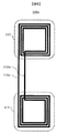
図13は、従来のインダクタ間の結合により通信を実現する半導体集積回路の概略構成を示す模式図である。図13(b)は、前記半導体集積回路の垂直断面図である。図13(b)は図13(a)におけるA−A’断面図であり、同じ符号で示される部分は同一のものである。図13において、半導体集積回路は送信側半導体チップ100と受信側半導体チップ200から成る。
FIG. 13 is a schematic diagram showing a schematic configuration of a semiconductor integrated circuit that realizes communication by coupling between conventional inductors. FIG. 13B is a vertical sectional view of the semiconductor integrated circuit. FIG. 13B is a cross-sectional view taken along the line A-A ′ in FIG. 13A, and the parts denoted by the same reference numerals are the same. In FIG. 13, the semiconductor integrated circuit includes a transmission-
図13(b)で示されるように、送信側半導体チップ100と受信側半導体チップ200は縦に積層され固定されている。送信側半導体チップ100上には、送信回路110a〜dが形成される。一方、受信側半導体チップ200上には、受信回路210a〜bが、それぞれ送信回路110a〜dと積層方向から見て対応する位置に形成される。図13(a)中の矢印は、対応する位置関係を示している。
As shown in FIG. 13B, the transmission-
しかしながら、上記の従来技術では、送信回路110a〜dと受信回路210a〜dは、それぞれの半導体チップ上において、積層方向から見て配置位置が異なる位置にあると、通信を行うことができない。
However, in the above-described prior art, the
特許文献1に記載の技術では、送信回路110a〜dと受信回路210a〜dが積層方向から見て離れた位置に形成されていると、前記送信回路と前記受信回路の間の電磁的な結合強度が低下し、正しく通信を行うことができない。
In the technique described in
また、特許文献2に記載の技術では、送信回路110a〜dの中心軸と受信回路201a〜dの中心軸とが、積層方向に対して一致していない場合、受信回路のインダクタに発生する誘導期電力の向きが変動してしまい、正しく通信を行うことができない。
Further, in the technique described in Patent Document 2, when the central axis of the
即ち、図13の半導体集積回路において、送信回路110a〜dと、受信回路210a〜dの配置が、積層方向から見て異なる位置にある半導体チップを積層することができないという問題があった。
That is, in the semiconductor integrated circuit of FIG. 13, there is a problem that the semiconductor chips in which the
本発明の目的は、上記の問題を解決し、インダクタ間の電磁的結合によって情報を伝送する積層型半導体集積回路において、送信回路110a〜dと受信回路210a〜dとが、積層方向から見て配置位置が異なる場合においても、半導体チップを積層することが可能となる半導体集積回路を提供することにある。
An object of the present invention is to solve the above-described problem, and in a stacked semiconductor integrated circuit that transmits information by electromagnetic coupling between inductors, the
上記問題を解決するために、本発明の半導体集積回路は、電磁的信号の送信回路を具備する第1半導体チップと、電磁的信号の受信回路を具備する第2半導体チップと、第1インダクタと第2インダクタを具備するインターポーザ基板とが積層される半導体集積回路であって、前記第1インダクタが前記第1半導体チップの送信回路と電磁的に結合し、前記第2インダクタが前記第2半導体チップの受信回路と電磁的に結合し、前記第1インダクタが受信した電磁的信号に対応した電磁的信号が第2インダクタから送信されることでチップ間通信を行うことを特徴とする。 In order to solve the above problems, a semiconductor integrated circuit according to the present invention includes a first semiconductor chip having an electromagnetic signal transmission circuit, a second semiconductor chip having an electromagnetic signal reception circuit, a first inductor, A semiconductor integrated circuit in which an interposer substrate having a second inductor is stacked, wherein the first inductor is electromagnetically coupled to a transmission circuit of the first semiconductor chip, and the second inductor is the second semiconductor chip. It is characterized in that inter-chip communication is performed by electromagnetically coupling to the receiving circuit of the first and second electromagnetic signals corresponding to the electromagnetic signal received by the first inductor.
本発明のインターポーザ基板は、前記第1インダクタと、前記第2インダクタとが、積層方向から見て異なる位置に配置されていることを特徴とする。 The interposer substrate of the present invention is characterized in that the first inductor and the second inductor are arranged at different positions when viewed from the stacking direction.
また、前記インターポーザ基板は、前記第1インダクタに誘導される起電力を動作電力源として利用して、前記第2インダクタから電磁的信号を送出することを特徴とする。 The interposer substrate may transmit an electromagnetic signal from the second inductor using an electromotive force induced in the first inductor as an operating power source.
また、本発明のインターポーザ基板は、電気的に信号を増幅する機能を具備した回路を介して、前記第2インダクタに接続されていることを特徴とする。 The interposer substrate of the present invention is characterized in that it is connected to the second inductor via a circuit having a function of electrically amplifying a signal.
さらに、本発明の半導体集積回路の製造法は、予め所定の導体パターンをインターポーザ基板に形成する工程と、前記導体パターンを加工して所定の素子特性に調整する工程とを備えることを特徴とする。 Furthermore, the method for manufacturing a semiconductor integrated circuit according to the present invention includes a step of forming a predetermined conductor pattern on an interposer substrate in advance, and a step of processing the conductor pattern to adjust to a predetermined element characteristic. .
本発明によれば、送信回路と受信回路が積層方向からみて異なる位置にある半導チップであっても、送信回路と受信回路の構成を変えることなく積層することが可能となり、多種・多様な半導体チップを積層する半導体集積回路を容易に実現することができる。 According to the present invention, even a semiconductor chip in which a transmission circuit and a reception circuit are at different positions when viewed from the stacking direction can be stacked without changing the configuration of the transmission circuit and the reception circuit. A semiconductor integrated circuit in which semiconductor chips are stacked can be easily realized.
また、本発明のインターポーザ基板によれば、インターポーザ基板に給電設備を設けることなく、離れた送信回路と受信回路間の通信を実現することが可能である。これにより、インターポーザ半導体チップの実装コストの大幅削減が可能である。 Further, according to the interposer substrate of the present invention, it is possible to realize communication between a remote transmission circuit and a reception circuit without providing a power supply facility on the interposer substrate. Thereby, the mounting cost of the interposer semiconductor chip can be greatly reduced.
また、本発明によれば、第1インダクタに誘導された起電力に重畳された信号を増幅して、第2インダクタに伝送することも可能であるため、1つの送信回路から、複数の受信回路に信号を伝送する場合に好適である。 Further, according to the present invention, it is possible to amplify a signal superimposed on the electromotive force induced in the first inductor and transmit the amplified signal to the second inductor. It is suitable when transmitting a signal.
本発明によれば、インターポーザ基板製造工程において導体パターンを精密に形成する操作が不要となり、例えば印刷技術などを利用してインターポーザ基板を簡便に製造することが可能となる。更に、インターポーザ上の導体パターンを別の工程で調整することで、所望のチップ間通信性能を半導体集積回路毎に個別に得ることが可能となる。 According to the present invention, it is not necessary to precisely form a conductor pattern in an interposer substrate manufacturing process, and it is possible to easily manufacture an interposer substrate using, for example, a printing technique. Furthermore, by adjusting the conductor pattern on the interposer in a separate process, it is possible to individually obtain a desired inter-chip communication performance for each semiconductor integrated circuit.
以下、本発明の実施の形態について、図面を参照して詳細に説明する。なお、本発明は以下の例に限定されるものではなく、本発明の要旨を逸脱しない範囲で、任意に変更可能であることは言うまでもない。 Hereinafter, embodiments of the present invention will be described in detail with reference to the drawings. Needless to say, the present invention is not limited to the following examples, and can be arbitrarily changed without departing from the gist of the present invention.
(構造)
図1(a)は、本発明による第1の実施形態に係る半導体集積回路の一例の概略構成を示した斜視図であり、図1(b)は、本実施形態における半導体集積回路を図1(a)のA−A’線に沿った方向で切断した断面図である。
(Construction)
FIG. 1A is a perspective view showing a schematic configuration of an example of a semiconductor integrated circuit according to the first embodiment of the present invention, and FIG. 1B shows the semiconductor integrated circuit in the present embodiment. It is sectional drawing cut | disconnected in the direction along the AA 'line of (a).
本実施の形態に係る半導体集積回路は、送信側半導体チップ100、受信側半導体チップ200、インターポーザ基板300、第1の電磁シールドフィルム400a、第2の電磁シールドフィルム400bが積層されている。
In the semiconductor integrated circuit according to the present embodiment, a transmission-
送信側半導体チップ100の表面には、送信回路110a〜dと、送信側処理回路120とが配置される。送信側処理回路120は、送信回路110a〜dに対してデータを入力する。
受信側半導体チップ200の表面には、受信回路210a〜dと、受信側処理回路220a〜cとが配置される。受信側処理回路220a〜cは、受信回路210a〜dのうち一つないし複数からデータを受信する。送信回路110a〜dと受信回路210a〜dは、同一のアルファベット符号が付与された送受信回路の組において、水平方向に対して異なる位置に、それぞれの基板上に配置されている。
On the surface of the receiving-
なお、送信回路110a〜dは、受信側処理回路220cに対して、積層方向から見て重なり合った位置に配置されている。また、受信回路210a〜dは、送信側処理回路120に対して、積層方向から見て重なり合った位置に配置されている。
Note that the
図2は、本実施例における送信回路110aの平面構成の一例を示した概略図である。送信回路110a〜dは、送信信号発生部111と、送信コイル112から成る。送信信号発生部111の出力は、送信コイル112と電気的に接続されている。前記送信信号発生部111は、入力されたデータに応じて、データが重畳された電流を送信コイル112に入力する。これらは、送信回路110b〜dについても、送信回路110aと同様の構成である。
FIG. 2 is a schematic diagram illustrating an example of a planar configuration of the
図3は、本実施例における受信回路210aの平面構成の一例を示した概略図である。受信回路210a〜dは、受信信号再生部211と、受信コイル212から成る。受信信号再生部211の入力は、受信コイル212と電気的に接続されている。受信信号再生部211は、受信コイル212に生じた誘導起電力の変化から、そこに重畳されたデータを取り出す。これらは、送信回路210b〜dについても、送信回路210aと同様の構成である。
FIG. 3 is a schematic diagram illustrating an example of a planar configuration of the
図2、図3記載の送信回路および受信回路は、例えば多層金属配線が利用可能な半導体プロセスにおいて、通常の半導体チップ上に実現される。インターポーザ基板300の表面には、通信中継部310a〜dが配置される。
The transmission circuit and the reception circuit described in FIGS. 2 and 3 are realized on a normal semiconductor chip in a semiconductor process in which, for example, multilayer metal wiring can be used.
図4は、本実施例における通信中継部310aの平面構成の一例を示した概略図である。通信中継部310aは、第1コイル311と、第2コイル312と、配線313a、bから成る。配線313a、bによって、第1コイル311と第2コイル312は電気的に接続されている。これらは、配線312a、bの形状が異なる場合があることを除き、通信中継部310b〜dについても同様の構成を取る。
FIG. 4 is a schematic diagram illustrating an example of a planar configuration of the
図1を参照して、送信回路110aと、受信回路210aと、通信中継部310aの配置について説明する。通信中継部310aにおける第1コイル311は、送信回路110aが具備する送信コイル112と中心軸が一致するように配置される。また、通信中継部310aにおける第2コイル312は、受信回路210aが具備する受信コイル212と中心軸が一致するように配置される。このため、前記第1コイル311と前記送信コイル112との間、および前記第2コイル312と前記受信コイル212との間で、それぞれ矢印L1、L2で示すような磁束により電磁的な結合を生じる。
The arrangement of the
これは、送信回路110b〜dと受信回路210b〜dと通信中継部310b〜dについて、同一のアルファベット符号が付与された組に対して、同様の配置関係で構成される。
前記通信中継部310は、例えば通常の半導体プロセスにおける配線層プロセスを用いて構成することができる。これにより、インターポーザ基板として、シリコン基板を用いることが可能である。
This is configured in a similar arrangement relationship with respect to the groups to which the same alphabetical code is assigned for the
The communication relay unit 310 can be configured using, for example, a wiring layer process in a normal semiconductor process. Thereby, a silicon substrate can be used as the interposer substrate.
電磁シールドフィルム400a、bは、その表面上の一部に電磁シールド部401a、bをそれぞれ具備する。電磁シールド部401a、bは、半導体チップの積層方向と平行方向に対して電磁波の透過を遮断する。
The
(動作)
次に、図1の半導体集積回路において、送信側処理装置120が、送信回路110aを用いて、受信側処理装置220aに対してデータを送信する動作について説明する。図1において、送信側処理回路120は、送信回路110aに対して送信するデータを入力する。
(Operation)
Next, in the semiconductor integrated circuit of FIG. 1, an operation in which the transmission
図2において、送信回路110aにおける送信信号発生部111は入力されたデータを重畳した電流を送信コイル112に対して出力する。これにより、送信コイル112を貫通する磁束L1が変動する。これに伴い、前記送信コイル112と誘導性結合する通信中継装置310aにおける第1コイル311において、誘導起電力が生成される。
In FIG. 2, the transmission
図4において、第1コイル311と第2コイル312は、配線313a、bによって直列に接続されている。このため、前記第1コイル311生じた誘導起電力によって、前記第2コイル312を貫通する磁束L2に変化が生じる。これに伴い、前記第2コイル312と誘導性結合する受信回路210aにおける受信コイル212において誘導起電力が生成される。
In FIG. 4, the
図3において、前記受信信号再生部211は、前記受信コイル212に発生した誘導起電力の変化に応じたデータを再生する。
In FIG. 3, the reception
従って、図1の半導体集積回路において、送信回路110aに入力されたデータは、通信中継部310aを介して、受信回路210aに伝送される。最終的に、受信側処理装置220aは、受信回路210aにおける受信再生部211から、データを受信する。
Therefore, in the semiconductor integrated circuit of FIG. 1, data input to the
ここでは送信回路110a、受信回路210a、通信中継部310aについて動作を説明したが、同一のアルファベットが付与された組に対しても同様の動作である。
Here, the operations of the
なお、電磁シールドフィルム400aにおける電磁シールド部401bは、送信回路101a〜dにおける送信コイル112から生じた磁束の変動が受信側半導体チップ200に伝送されることを遮断する。すなわち、磁束L1の変動により受信側回路220cの内部回路および配線構造が影響を受けて誤動作することを防止する。また、同様に、通信中継部301a〜dにおける第2コイル312から生じる磁束L2の変動は、電磁シールドフィルム400bにおける電磁シールド部401bによって送信側半導体チップ100に伝送されることを遮断される。
In addition, the
(変形例)
(1)半導体チップの数
本実施例において、半導体チップを2個積層した例を説明したが、これに限定するものではない。3個以上の半導体チップを積層する場合でも、各半導体チップ間に、適当な通信中継部が配置されたインターポーザ基板を積層すればよい。
(Modification)
(1) Several semiconductor chips In this embodiment, an example in which two semiconductor chips are stacked has been described. However, the present invention is not limited to this. Even when three or more semiconductor chips are stacked, an interposer substrate on which an appropriate communication relay unit is disposed may be stacked between the semiconductor chips.
また、積層方向の拡張だけではなく、水平方向の拡張も可能である。例えば、受信側半導体チップを2つ水平方向に配置した例を図5に示す。なお、図5において、図1と対応する部分については同一符号を付し、その詳細説明は繰り返さない。 Further, not only expansion in the stacking direction but also expansion in the horizontal direction is possible. For example, FIG. 5 shows an example in which two receiving-side semiconductor chips are arranged in the horizontal direction. In FIG. 5, parts corresponding to those in FIG. 1 are denoted by the same reference numerals, and detailed description thereof will not be repeated.
図5において、受信側半導体チップ201a、bは、インターポーザ基板300の上方に水平に並べて配置される。これにより、送信側半導体チップ100は、適切な送信回路110a〜dを選択することで、受信側半導体チップ201aおよび201bに対して通信可能となる。
In FIG. 5, the receiving-
(2)通信中継部におけるコイルの配置
本実施例において、通信中継部310a〜dは、全てインターポーザ基板の片側の面に形成されている例を説明したが、これに限定されるものではない。例えば、図6に、一部の構造を底面に配置する例を示す。
(2) Arrangement of coils in communication relay unit In the present embodiment, the
図6(a)はインターポーザ基板301の上面を示した図であって、図6(b)は、インターポーザ基板301の底面を示した図であって、図6(c)は、図6(a)におけるB−B’線でインターポーザ基板を切断した断面図である。 6A is a diagram showing the top surface of the interposer substrate 301, FIG. 6B is a diagram showing the bottom surface of the interposer substrate 301, and FIG. 6C is a diagram showing FIG. It is sectional drawing which cut | disconnected the interposer board | substrate by the BB 'line | wire in ().
図6のインターポーザ基板を参照して、図1に示されるインターポーザ基板と異なる点は、通信中継部が、インターポーザ基板301の底面に配置される通信中継入力部331a〜dと、インターポーザ基板301の上面に配置される通信中継出力部332a〜dに分割されている点である。
Referring to the interposer substrate of FIG. 6, the difference from the interposer substrate shown in FIG. It is the point which is divided | segmented into the communication
なお、図6(c)を参照して、通信中継入力部331aと通信中継332aは、スルーホール333によって電気的に接続されている。また、通信中継入力部331b〜dおよび通信中継出力部332b〜dにおいて、同一のアルファベット符号を付した組については、同様の構成で接続されている。
6C, the communication
通信中継入力部331を底面に配置した目的は、送信側半導体チップ上の送信回路との電磁的結合強度を高めることである。これにより、送信回路の消費電力を抑えることが可能である。
このように、通信中継部は、通信中継入力部331と通信中継出力部332が電気的に接続されていればよい。このため、通信中継部は、所望の性能を実現するためにインターポーザ基板上のいかなる位置に配置してもよい。
The purpose of arranging the communication relay input unit 331 on the bottom surface is to increase the electromagnetic coupling strength with the transmission circuit on the transmission side semiconductor chip. Thereby, the power consumption of the transmission circuit can be suppressed.
As described above, the communication relay unit only needs to be electrically connected to the communication relay input unit 331 and the communication relay output unit 332. For this reason, the communication relay unit may be arranged at any position on the interposer substrate in order to achieve a desired performance.
(3)送受信回路の配置
本実施例で説明した半導体集積回路において、送信回路110a〜dは全て送信側半導体チップ100に形成され、受信回路210a〜dは全て受信側チップ200に形成されているが、これに限定するものではない。通信中継部310a〜dにおいて、どちらか一方のコイルが送信回路と電磁的結合し、もう一方のコイルが受信回路と電磁的に結合されていれば、送信回路もしくは受信回路を配置する半導体チップは限定されない。
(3) Arrangement of Transmission / Reception Circuits In the semiconductor integrated circuit described in the present embodiment, the
また、送受信回路は半導体チップにおいて、一つの面にのみ配置する必要はなく、インターポーザ基板上の通信中継部と電磁的に結合されていれば、いかなる面に配置しても良いことは言うまでもない。 Further, it is needless to say that the transmission / reception circuit need not be disposed on only one surface of the semiconductor chip, and may be disposed on any surface as long as it is electromagnetically coupled to the communication relay unit on the interposer substrate.
(4)通信中継部の使用箇所
本実施例で説明した半導体集積回路において、送信回路110a〜dから伝送される信号は全て中継装置310a〜dを介して、受信回路210a〜dに中継されるが、これに限定するものではない。例えば、一部の送信回路の信号伝送だけが、通信中継部を介して受信送信へ伝送される半導体集積回路の概略構成を図7に示す。なお、図7において、図1と対応する部分については同一符号を付し、その詳細説明は繰り返さない。図7において、送信回路110aおよび110dから送信される信号は、インターポーザ基板300を通過して、受信回路210aおよび210dに直接伝送される例である。
(4) Use Location of Communication Relay Unit In the semiconductor integrated circuit described in this embodiment, all signals transmitted from the
(5)インターポーザ基板の材料
本実施例において、インターポーザ基板300はシリコン基板によって実現されると説明したが、これに限定されるものではなく、基板上に所望の動作を実現する通信中継部を形成することが可能であれば、いかなる材料を用いても良い。
たとえば、インターポーザ基板300は、ポリイミドフィルムなどの合成樹脂フィルム上に導電性材料もしくは絶縁性材料を、所定のパターン状に蒸着させることでも構成可能である。
(5) Interposer Substrate Material In this embodiment, it has been described that the
For example, the
また、蒸着以外の方法として、例えば前記合成樹脂フィルム上に、合成樹脂を用いた銀ペーストを所定の導体パターンで印刷することで構成可能である。
以上のような方法を用いる利点は、シリコン基板を用いる方法に比べ、安価で実現できる点である。
Moreover, as a method other than vapor deposition, for example, a silver paste using a synthetic resin can be printed on the synthetic resin film with a predetermined conductor pattern.
The advantage of using the above method is that it can be realized at a lower cost than the method using a silicon substrate.
(6)コイルの形状
図2、図3、図4において、平面上に四角形で巻線を構成したコイルを用いた例を示したが、これに限定するものではない。送信回路110a〜dと通信中継部310a〜dの間で、所定の結合強度が得られるものであれば、他の形状の平面インダクタを用いても良い。受信回路210a〜dと通信中継部310a〜dの間においても同様であることは、言うまでもない。
(6) Shape of coil Although FIGS. 2, 3, and 4 show examples in which a coil having a rectangular winding on a plane is used, the present invention is not limited to this. As long as a predetermined coupling strength can be obtained between the
図8は、本発明による第2の実施形態に係る半導体集積回路の概略の構成を示した模式図であって、図1と対比される図である。 FIG. 8 is a schematic diagram showing a schematic configuration of a semiconductor integrated circuit according to the second embodiment of the present invention, which is compared with FIG.
図8の半導体集積回路を参照して、図1で示される半導体集積回路と異なる点は、通信中継部320が、受信回路220b、cと通信を行う点である。これにより、送信回路110bから送信された信号を、受信回路210b、210cへと伝送することができる。なお、図8において、図1と対応する部分については同一符号を付し、その詳細説明は繰り返さない。
Referring to the semiconductor integrated circuit of FIG. 8, the difference from the semiconductor integrated circuit shown in FIG. 1 is that the
図9は、本実施例における通信中継部320の平面構成の一例を示した概略図である。通信中継部320は、第1コイル321と、第2コイル322b、cと、3つのコイルを接続する配線からなる。第1コイル321は、図8における送信回路110bが具備する送信コイル112と電磁的結合を生じる。第2コイル322bは、図5における受信回路210bが具備する受信コイル212と電磁的結合を生じる。同様に、第2コイル322cは、図8における受信回路210cが具備する受信コイル212と電磁的結合を生じる。
FIG. 9 is a schematic diagram illustrating an example of a planar configuration of the
図10は、本実施例における通信中継部320の別の平面構成の例を示した概略図である。通信中継部320は、第1コイルと第2コイルが電気的に直列に接続された構造を、第1コイルの中心軸が同一となるように配置した例である。
FIG. 10 is a schematic diagram illustrating an example of another planar configuration of the
なお、本実施例では第2コイルが2つの例を説明したが、これに限定されるものではなく、第2コイルが3つ以上ある場合に対しても有効である。
なお、本実施例では受信回路210b、210cが同一の半導体チップにある場合を説明したが、これに限定されるものではない。例えば、受信回路210b、210cが、それぞれ別の半導体チップにある場合に対しても有効である。
In addition, although the example which has two 2nd coils was demonstrated in the present Example, it is not limited to this, It is effective also with respect to the case where there are three or more 2nd coils.
In this embodiment, the case where the receiving
図11は、本発明の第3の実施の形態における通信中継部340の平面構成を示した図であって、図4と対比される図である。図11の通信中継部340を参照して、図4で示される通信中継部310と異なる点は、配線313a、bの代わりに、信号増幅部341に置換されている点である。
FIG. 11 is a diagram illustrating a planar configuration of the
信号増幅部341は、通信中継部340において、第1コイル311に生じた誘導起電力に重畳された信号を、第2コイル312に伝送する際に、その信号を増幅する動作を行う。信号増幅部341の実現方法の1つの構成例を、図12に示す。
The
図12において、抵抗性素子、容量性素子、誘導性素子などの受動素子342a〜fを梯子状に接続し、所定の周波数に対して共振特性を持つ伝送経路が形成されている。前記周波数と、送信回路110からデータを伝送する周波数を一致させることにより、第1コイルおよび第2コイルに発生する起電力の振幅を増幅することができる。これにより、少ない電力で受信回路210までデータ伝送を実現することができる。なお、前記受動素子342a〜fは、例えば、所定の形状を持つ導体パターンをインターポーザ基板300上に形成することで構成される。
In FIG. 12,
前記導体パターンは、予め十分な面積を持った矩形の導体パターンをインターポーザ基板300の表面上に設けておき、インターポーザ基板300の製造後に所定の特性を持つ導体構造に加工する方法で形成する。例えば、ポリイミドフィルムなどの合成樹脂フィルム上に導電性材料を大まかに蒸着させる工程と、それをレーザートリミングによって所定の形状に加工する工程とを備える、インターポーザ基板製造方法によって実現できる。
The conductor pattern is formed by a method in which a rectangular conductor pattern having a sufficient area is provided on the surface of the
(変形例)
本実施例において、受動素子342を用いて信号増幅部341を構成する例を説明したが、信号増幅部341の構成はこれに限定するものではない。例えば、受動素子342a〜fの一部もしくは全てを、トランジスタや演算増幅器などの能動素子もしくは電子回路に置き換えて、より信号増幅利得を向上させた構造でもよい。
(Modification)
In this embodiment, the example in which the
100…送信側半導体チップ、110a〜d…送信回路、111…送信信号発生部、112…送信コイル、120…送信側処理回路、200、201a、201b…受信側半導体チップ、210a〜d…受信回路、211…受信信号再生部、212…受信コイル、220a〜c…受信側処理回路、300…インターポーザ基板、310a〜d、320…通信中継部、311、321…第1コイル、312、322a、322b、324、325…第2コイル、313a、b…配線部、331a〜d…通信中継入力部、332a〜d…通信中継出力部、333…スルーホール、341…信号増幅部、342a〜f…受動素子、400a、b…電磁シールドフィルム、410a、b…電磁シールド部
DESCRIPTION OF
Claims (9)
電磁信号の送信回路を有する第1の半導体チップと、
電磁信号の受信回路を有する第2の半導体チップと、
前記第1の半導体チップの送信回路に電磁結合する第1のインダクタと前記第2の半導体チップの受信回路に電磁結合する第2のインダクタを有し、前記第1のインダクタと第2のインダクタが電気的に接続されているインターポーザ基板と、を備え、
前記第1の半導体チップから前記第2の半導体チップにチップ間通信されることを特徴とする半導体集積回路。 In a semiconductor integrated circuit configured by laminating a plurality of semiconductor chips,
A first semiconductor chip having an electromagnetic signal transmission circuit;
A second semiconductor chip having an electromagnetic signal receiving circuit;
A first inductor that is electromagnetically coupled to a transmission circuit of the first semiconductor chip; and a second inductor that is electromagnetically coupled to a reception circuit of the second semiconductor chip, wherein the first inductor and the second inductor are An interposer substrate electrically connected,
A semiconductor integrated circuit, wherein inter-chip communication is performed from the first semiconductor chip to the second semiconductor chip.
前記インターポーザ基板は前記第1の半導体チップと前記第2の半導体チップの間に積層され、
前記第1のインダクタは前記第1の半導体チップの送信回路に対向して配置され、
前記第2のインダクタは前記第2の半導体チップの受信回路に対向して配置され、
前記第1のインダクタと前記第2のインダクタは積層方向からみて異なる位置に配置されることを特徴とする半導体集積回路。 The semiconductor integrated circuit according to claim 1,
The interposer substrate is stacked between the first semiconductor chip and the second semiconductor chip,
The first inductor is disposed opposite the transmission circuit of the first semiconductor chip;
The second inductor is disposed to face the receiving circuit of the second semiconductor chip,
The semiconductor integrated circuit, wherein the first inductor and the second inductor are arranged at different positions as viewed from the stacking direction.
前記インターポーザ基板と前記第2の半導体チップと間に前記前記第1の半導体チップの送信回路と前記第1のインダクタの電磁結合を遮断する第2の電磁シールド部を有し、
前記インターポーザ基板と前記第1の半導体チップと間に前記第1のインダクタと前記前記第2の半導体チップの受信回路との電磁結合を遮断する第1の電磁シールド部を有することを特徴とする半導体集積回路。 The semiconductor integrated circuit according to claim 2,
A second electromagnetic shield portion for blocking electromagnetic coupling between the transmission circuit of the first semiconductor chip and the first inductor between the interposer substrate and the second semiconductor chip;
A semiconductor having a first electromagnetic shield part for blocking electromagnetic coupling between the first inductor and the receiving circuit of the second semiconductor chip between the interposer substrate and the first semiconductor chip. Integrated circuit.
前記第1のインダクタと前記第2のインダクタは前記インターポーザ基板に配設され、
前記第1のインダクタと前記第2のインダクタはスルーホールを介して接続されることを特徴とする半導体集積回路。 The semiconductor integrated circuit according to any one of claims 1 to 3,
The first inductor and the second inductor are disposed on the interposer substrate;
The semiconductor integrated circuit, wherein the first inductor and the second inductor are connected through a through hole.
前記インターポーザ基板は、さらに、第3のインダクタを有し、
前記第3のインダクタは前記第1のインダクタと前記第2のインダクタに直列接続されていることを特徴とする半導体集積回路。 The semiconductor integrated circuit according to any one of claims 1 to 3,
The interposer substrate further includes a third inductor,
The semiconductor integrated circuit, wherein the third inductor is connected in series to the first inductor and the second inductor.
前記インターポーザ基板は、さらに、第3のインダクタを有し、
前記第3のインダクタは前記第1のインダクタと前記第2のインダクタに独立に接続する2重のコイル部を有することを特徴とする半導体集積回路。 The semiconductor integrated circuit according to any one of claims 1 to 3,
The interposer substrate further includes a third inductor,
3. The semiconductor integrated circuit according to claim 1, wherein the third inductor has a double coil portion that is independently connected to the first inductor and the second inductor.
前記インターポーザ基板は受動素子を有し、
前記第2のインダクタは、前記受動素子を介して前記第1のインダクタに接続されることを特徴とする半導体集積回路。 The semiconductor integrated circuit according to any one of claims 1 to 3,
The interposer substrate has passive elements;
The semiconductor integrated circuit, wherein the second inductor is connected to the first inductor through the passive element.
前記インターポーザ基板は能動素子を有し、
前記第2のインダクタは、前記能動素子を介して前記第1のインダクタに接続されることを特徴とする半導体集積回路。 The semiconductor integrated circuit according to any one of claims 1 to 3,
The interposer substrate has active elements;
The semiconductor integrated circuit, wherein the second inductor is connected to the first inductor through the active element.
前記インターポーザ基板の能動素子は、前記前記第1のインダクタを介して電力供給されることを特徴とする半導体集積回路。 The semiconductor integrated circuit according to claim 8, wherein
An active element of the interposer substrate is supplied with electric power through the first inductor.
Priority Applications (2)
| Application Number | Priority Date | Filing Date | Title |
|---|---|---|---|
| JP2008279064A JP5216532B2 (en) | 2008-10-30 | 2008-10-30 | Semiconductor integrated circuit |
| US12/608,307 US8125059B2 (en) | 2008-10-30 | 2009-10-29 | Semiconductor device |
Applications Claiming Priority (1)
| Application Number | Priority Date | Filing Date | Title |
|---|---|---|---|
| JP2008279064A JP5216532B2 (en) | 2008-10-30 | 2008-10-30 | Semiconductor integrated circuit |
Publications (2)
| Publication Number | Publication Date |
|---|---|
| JP2010109112A JP2010109112A (en) | 2010-05-13 |
| JP5216532B2 true JP5216532B2 (en) | 2013-06-19 |
Family
ID=42130377
Family Applications (1)
| Application Number | Title | Priority Date | Filing Date |
|---|---|---|---|
| JP2008279064A Expired - Fee Related JP5216532B2 (en) | 2008-10-30 | 2008-10-30 | Semiconductor integrated circuit |
Country Status (2)
| Country | Link |
|---|---|
| US (1) | US8125059B2 (en) |
| JP (1) | JP5216532B2 (en) |
Families Citing this family (22)
| Publication number | Priority date | Publication date | Assignee | Title |
|---|---|---|---|---|
| JP5578797B2 (en) | 2009-03-13 | 2014-08-27 | ルネサスエレクトロニクス株式会社 | Semiconductor device |
| US9059026B2 (en) | 2010-06-01 | 2015-06-16 | Taiwan Semiconductor Manufacturing Company, Ltd. | 3-D inductor and transformer |
| US8823133B2 (en) * | 2011-03-29 | 2014-09-02 | Xilinx, Inc. | Interposer having an inductor |
| US9406738B2 (en) | 2011-07-20 | 2016-08-02 | Xilinx, Inc. | Inductive structure formed using through silicon vias |
| KR101872522B1 (en) * | 2011-09-26 | 2018-06-29 | 삼성전기주식회사 | Cmos power amplifier using power combiner |
| US9330823B1 (en) | 2011-12-19 | 2016-05-03 | Xilinx, Inc. | Integrated circuit structure with inductor in silicon interposer |
| US9337138B1 (en) | 2012-03-09 | 2016-05-10 | Xilinx, Inc. | Capacitors within an interposer coupled to supply and ground planes of a substrate |
| US9041152B2 (en) | 2013-03-14 | 2015-05-26 | Taiwan Semiconductor Manufacturing Company, Ltd. | Inductor with magnetic material |
| US20180025189A1 (en) * | 2015-02-19 | 2018-01-25 | Pezy Computing K.K. | Signal processing device |
| WO2016157387A1 (en) * | 2015-03-30 | 2016-10-06 | 株式会社PEZY Computing | Semiconductor device |
| EP3324428B1 (en) * | 2015-07-16 | 2019-09-04 | Pezy Computing K.K. | Semiconductor switch device |
| US10304806B2 (en) | 2015-07-16 | 2019-05-28 | Pezy Computing K.K. | Semiconductor device |
| JP6570954B2 (en) * | 2015-09-30 | 2019-09-04 | 学校法人慶應義塾 | Semiconductor chip and multichip module |
| US10068856B2 (en) * | 2016-07-12 | 2018-09-04 | Mediatek Inc. | Integrated circuit apparatus |
| JP2018050096A (en) * | 2016-09-20 | 2018-03-29 | 日本電信電話株式会社 | Integrated circuit device |
| US10700028B2 (en) | 2018-02-09 | 2020-06-30 | Sandisk Technologies Llc | Vertical chip interposer and method of making a chip assembly containing the vertical chip interposer |
| US10475877B1 (en) * | 2018-08-21 | 2019-11-12 | Taiwan Semiconductor Manufacturing Co., Ltd. | Multi-terminal inductor for integrated circuit |
| US10879260B2 (en) | 2019-02-28 | 2020-12-29 | Sandisk Technologies Llc | Bonded assembly of a support die and plural memory dies containing laterally shifted vertical interconnections and methods for making the same |
| US11037885B2 (en) * | 2019-08-12 | 2021-06-15 | Taiwan Semiconductor Manufacturing Co., Ltd. | Semiconductor packaging device comprising a shield structure |
| WO2021224982A1 (en) * | 2020-05-08 | 2021-11-11 | ウルトラメモリ株式会社 | Semiconductor device |
| JP7352992B2 (en) * | 2020-05-11 | 2023-09-29 | ウルトラメモリ株式会社 | Semiconductor device and its manufacturing method |
| US20230014046A1 (en) * | 2021-07-13 | 2023-01-19 | Mediatek Inc. | Semiconductor devices with in-package PGS for coupling noise suppression |
Family Cites Families (10)
| Publication number | Priority date | Publication date | Assignee | Title |
|---|---|---|---|---|
| US5111169A (en) * | 1989-03-23 | 1992-05-05 | Takeshi Ikeda | Lc noise filter |
| JP4295124B2 (en) * | 2004-01-19 | 2009-07-15 | 株式会社エイアールテック | Semiconductor device |
| JP4131544B2 (en) * | 2004-02-13 | 2008-08-13 | 学校法人慶應義塾 | Electronic circuit |
| JP4752369B2 (en) * | 2004-08-24 | 2011-08-17 | ソニー株式会社 | Semiconductor device and substrate |
| JP2006173415A (en) * | 2004-12-16 | 2006-06-29 | Keio Gijuku | Electronic circuit |
| WO2007029384A1 (en) * | 2005-09-06 | 2007-03-15 | Nec Corporation | Semiconductor device |
| JP2007165459A (en) * | 2005-12-12 | 2007-06-28 | Mitsubishi Electric Corp | Multi-chip module |
| JP4725346B2 (en) * | 2006-02-08 | 2011-07-13 | ソニー株式会社 | Semiconductor device |
| JP4325630B2 (en) * | 2006-03-14 | 2009-09-02 | ソニー株式会社 | 3D integration device |
| JP4878502B2 (en) * | 2006-05-29 | 2012-02-15 | ルネサスエレクトロニクス株式会社 | Semiconductor device |
-
2008
- 2008-10-30 JP JP2008279064A patent/JP5216532B2/en not_active Expired - Fee Related
-
2009
- 2009-10-29 US US12/608,307 patent/US8125059B2/en not_active Expired - Fee Related
Also Published As
| Publication number | Publication date |
|---|---|
| US20100109133A1 (en) | 2010-05-06 |
| US8125059B2 (en) | 2012-02-28 |
| JP2010109112A (en) | 2010-05-13 |
Similar Documents
| Publication | Publication Date | Title |
|---|---|---|
| JP5216532B2 (en) | Semiconductor integrated circuit | |
| JP6414614B2 (en) | Article | |
| JP6260729B2 (en) | Feeding element | |
| JP5522227B2 (en) | Mobile communication terminal | |
| JP5435130B2 (en) | Communication terminal device and antenna device | |
| EP2928015B1 (en) | Radio frequency ic device and electronic apparatus | |
| US10396429B2 (en) | Wireless communication device | |
| US20140184462A1 (en) | Antenna module and radio communication device | |
| US20090058589A1 (en) | Suspension inductor devices | |
| EP3041087B1 (en) | Wireless communication device | |
| JP2016197864A (en) | Antenna device | |
| JPWO2009110381A1 (en) | Wireless IC device and wireless communication system | |
| CN101622756A (en) | Antenna coil for mounting on circuit board | |
| JP5734217B2 (en) | Semiconductor device | |
| US10454440B2 (en) | Directional coupler and wireless communication device using the same | |
| KR102022706B1 (en) | Antenna module | |
| JP6508441B1 (en) | Article with RFIC chip | |
| JP4592542B2 (en) | Semiconductor device | |
| WO2010013426A1 (en) | Non-contact electronic device | |
| JP5668894B2 (en) | Wireless IC device and wireless communication terminal | |
| CN110781696A (en) | Non-contact communication module and card reader | |
| KR20110072278A (en) | Electronic device with inductively coupled communication means |
Legal Events
| Date | Code | Title | Description |
|---|---|---|---|
| A621 | Written request for application examination |
Free format text: JAPANESE INTERMEDIATE CODE: A621 Effective date: 20110523 |
|
| A977 | Report on retrieval |
Free format text: JAPANESE INTERMEDIATE CODE: A971007 Effective date: 20120227 |
|
| TRDD | Decision of grant or rejection written | ||
| A01 | Written decision to grant a patent or to grant a registration (utility model) |
Free format text: JAPANESE INTERMEDIATE CODE: A01 Effective date: 20130205 |
|
| A61 | First payment of annual fees (during grant procedure) |
Free format text: JAPANESE INTERMEDIATE CODE: A61 Effective date: 20130304 |
|
| R151 | Written notification of patent or utility model registration |
Ref document number: 5216532 Country of ref document: JP Free format text: JAPANESE INTERMEDIATE CODE: R151 |
|
| FPAY | Renewal fee payment (event date is renewal date of database) |
Free format text: PAYMENT UNTIL: 20160308 Year of fee payment: 3 |
|
| LAPS | Cancellation because of no payment of annual fees |