JP5210558B2 - Vibration isolator - Google Patents
Vibration isolator Download PDFInfo
- Publication number
- JP5210558B2 JP5210558B2 JP2007183405A JP2007183405A JP5210558B2 JP 5210558 B2 JP5210558 B2 JP 5210558B2 JP 2007183405 A JP2007183405 A JP 2007183405A JP 2007183405 A JP2007183405 A JP 2007183405A JP 5210558 B2 JP5210558 B2 JP 5210558B2
- Authority
- JP
- Japan
- Prior art keywords
- liquid chamber
- diaphragm
- vibration
- input
- main liquid
- Prior art date
- Legal status (The legal status is an assumption and is not a legal conclusion. Google has not performed a legal analysis and makes no representation as to the accuracy of the status listed.)
- Expired - Fee Related
Links
- 239000007788 liquid Substances 0.000 claims description 109
- 230000003068 static effect Effects 0.000 claims description 20
- 238000005192 partition Methods 0.000 claims description 13
- 230000002093 peripheral effect Effects 0.000 claims description 11
- 238000000638 solvent extraction Methods 0.000 claims 1
- 239000012530 fluid Substances 0.000 description 26
- 238000004891 communication Methods 0.000 description 8
- 239000002184 metal Substances 0.000 description 6
- LYCAIKOWRPUZTN-UHFFFAOYSA-N Ethylene glycol Chemical compound OCCO LYCAIKOWRPUZTN-UHFFFAOYSA-N 0.000 description 3
- 238000004519 manufacturing process Methods 0.000 description 3
- 239000012528 membrane Substances 0.000 description 3
- 230000002159 abnormal effect Effects 0.000 description 2
- 239000013013 elastic material Substances 0.000 description 2
- 238000003780 insertion Methods 0.000 description 2
- 230000037431 insertion Effects 0.000 description 2
- NINIDFKCEFEMDL-UHFFFAOYSA-N Sulfur Chemical group [S] NINIDFKCEFEMDL-UHFFFAOYSA-N 0.000 description 1
- 239000006096 absorbing agent Substances 0.000 description 1
- 238000010521 absorption reaction Methods 0.000 description 1
- 230000005540 biological transmission Effects 0.000 description 1
- 238000007796 conventional method Methods 0.000 description 1
- 238000002474 experimental method Methods 0.000 description 1
- 239000000463 material Substances 0.000 description 1
- 238000012986 modification Methods 0.000 description 1
- 230000004048 modification Effects 0.000 description 1
- 229910052717 sulfur Inorganic materials 0.000 description 1
- 239000011593 sulfur Substances 0.000 description 1
- 239000000725 suspension Substances 0.000 description 1
- XLYOFNOQVPJJNP-UHFFFAOYSA-N water Substances O XLYOFNOQVPJJNP-UHFFFAOYSA-N 0.000 description 1
Images

Classifications
-
- F—MECHANICAL ENGINEERING; LIGHTING; HEATING; WEAPONS; BLASTING
- F16—ENGINEERING ELEMENTS AND UNITS; GENERAL MEASURES FOR PRODUCING AND MAINTAINING EFFECTIVE FUNCTIONING OF MACHINES OR INSTALLATIONS; THERMAL INSULATION IN GENERAL
- F16F—SPRINGS; SHOCK-ABSORBERS; MEANS FOR DAMPING VIBRATION
- F16F13/00—Units comprising springs of the non-fluid type as well as vibration-dampers, shock-absorbers, or fluid springs
- F16F13/04—Units comprising springs of the non-fluid type as well as vibration-dampers, shock-absorbers, or fluid springs comprising both a plastics spring and a damper, e.g. a friction damper
- F16F13/06—Units comprising springs of the non-fluid type as well as vibration-dampers, shock-absorbers, or fluid springs comprising both a plastics spring and a damper, e.g. a friction damper the damper being a fluid damper, e.g. the plastics spring not forming a part of the wall of the fluid chamber of the damper
- F16F13/08—Units comprising springs of the non-fluid type as well as vibration-dampers, shock-absorbers, or fluid springs comprising both a plastics spring and a damper, e.g. a friction damper the damper being a fluid damper, e.g. the plastics spring not forming a part of the wall of the fluid chamber of the damper the plastics spring forming at least a part of the wall of the fluid chamber of the damper
- F16F13/10—Units comprising springs of the non-fluid type as well as vibration-dampers, shock-absorbers, or fluid springs comprising both a plastics spring and a damper, e.g. a friction damper the damper being a fluid damper, e.g. the plastics spring not forming a part of the wall of the fluid chamber of the damper the plastics spring forming at least a part of the wall of the fluid chamber of the damper the wall being at least in part formed by a flexible membrane or the like
- F16F13/102—Units comprising springs of the non-fluid type as well as vibration-dampers, shock-absorbers, or fluid springs comprising both a plastics spring and a damper, e.g. a friction damper the damper being a fluid damper, e.g. the plastics spring not forming a part of the wall of the fluid chamber of the damper the plastics spring forming at least a part of the wall of the fluid chamber of the damper the wall being at least in part formed by a flexible membrane or the like characterised by features of flexible walls of equilibration chambers; decoupling or self-tuning means
Landscapes
- Engineering & Computer Science (AREA)
- General Engineering & Computer Science (AREA)
- Mechanical Engineering (AREA)
- Combined Devices Of Dampers And Springs (AREA)
Description
本発明は、例えば自動車、一般産業用機械等に適用され、エンジン等の振動発生部から車体等の振動受け部へ伝達される振動を遮断及び吸収する防振装置に関する。 The present invention relates to a vibration isolator that is applied to, for example, automobiles, general industrial machines, and the like, and blocks and absorbs vibration transmitted from a vibration generating unit such as an engine to a vibration receiving unit such as a vehicle body.
自動車には、エンジンと車体(フレーム)との間で振動伝達を阻止するために流体封入式エンジンマウント(防振装置)が配置されている。この種のエンジンマウントは、外筒金具(第1部材)と内筒金具(第2部材)とを弾性体により連結するとともに、外筒金具の一端の開口部が、外筒金具の内側に向けて突出するダイヤフラムにより閉塞されているものである。そして、ダイヤフラムと弾性体との間に形成された空間を仕切部材により主液室と副液室とに区画し、これら主液室と副液室とをシェイクオリフィス等のオリフィス通路により連通させたものである。 In an automobile, a fluid-filled engine mount (anti-vibration device) is disposed in order to prevent vibration transmission between the engine and the vehicle body (frame). This type of engine mount connects an outer cylinder fitting (first member) and an inner cylinder fitting (second member) with an elastic body, and an opening at one end of the outer cylinder fitting is directed toward the inside of the outer cylinder fitting. It is blocked by a projecting diaphragm. A space formed between the diaphragm and the elastic body is partitioned into a main liquid chamber and a sub liquid chamber by a partition member, and the main liquid chamber and the sub liquid chamber are communicated with each other by an orifice passage such as a shake orifice. Is.
例えば、特許文献1に示すエンジンマウントは、蓋に形成された外気と連通する開口から空気室内へ圧力流体を注入してダイヤフラムを仕切り板へ圧接し、この状態において本体部に形成された外気と連通する孔からゴム弾性体に囲まれた室に流体を所定量充填することで、静荷重がかかった状態においてダイヤフラムに負荷がかからない状態にしているものがある。
ところで、上述のエンジンマウントでは、路面の凹凸等により大きな振動荷重(バウンド荷重)が入力され、主液室内の液圧が急激に上昇した後に、逆方向の荷重(リバウンド荷重)が入力されると、主液室の液圧が負圧になることがある。主液室内の液圧が負圧になると、主液室内の流体中に多数の気泡が生成されるキャビテーションが発生する。キャビテーションは、その後の液圧変化(圧力上昇)に伴って気泡が消滅する時に異音を発生し、その異音が車室内に伝達されることから静粛性の悪化を招くことになる。また液圧上昇の開始後に気泡が完全に消滅するまでに一定の時間を要することから、入力振動に対する主液室の液圧変化量が小さくなり、エンジンマウントの振動吸収性能を低下させる原因ともなる。 By the way, in the above-described engine mount, when a large vibration load (bound load) is input due to road surface unevenness, etc., and the reverse pressure (rebound load) is input after the fluid pressure in the main fluid chamber suddenly increases. The liquid pressure in the main liquid chamber may become negative. When the liquid pressure in the main liquid chamber becomes negative, cavitation that generates a large number of bubbles in the fluid in the main liquid chamber occurs. Cavitation generates an abnormal noise when bubbles disappear with a subsequent hydraulic pressure change (pressure increase), and the abnormal noise is transmitted to the passenger compartment, resulting in a decrease in quietness. In addition, since a certain amount of time is required for the bubbles to disappear completely after the start of the hydraulic pressure rise, the amount of change in the hydraulic pressure in the main fluid chamber with respect to the input vibration is reduced, which may cause a decrease in the vibration absorption performance of the engine mount. .
特許文献1のエンジンマウントにあっては、キャビテーションを起こしうる大きなバウンド荷重が入力されて主液室内の液圧が急激に上昇すると、主液室内の流体が大量に副液室側へ流入する。そして、前記バウンド荷重に対するリバウンド荷重が入力されると、主液室は急激に元の体積に復元しようとする。しかしながら、特許文献1のエンジンマウントはダイヤフラムにほとんど負荷がかからない状態になっているので、副液室内の液圧は大気圧程度であり、副液室に流入した流体が主液室に戻りにくくなっている。その結果、主液室内が負圧となりやすく、キャビテーションが発生しやすくなるという問題がある。 In the engine mount of Patent Document 1, when a large bounce load that can cause cavitation is input and the hydraulic pressure in the main liquid chamber suddenly rises, a large amount of fluid in the main liquid chamber flows into the sub liquid chamber side. And if the rebound load with respect to the said bound load is input, the main liquid chamber will try to restore | restore rapidly to the original volume. However, since the engine mount of Patent Document 1 is in a state where a load is hardly applied to the diaphragm, the liquid pressure in the sub liquid chamber is about atmospheric pressure, and the fluid flowing into the sub liquid chamber is difficult to return to the main liquid chamber. ing. As a result, there is a problem that the main liquid chamber tends to be under negative pressure and cavitation is likely to occur.
本発明は、上述した事情に鑑みてなされたものであって、キャビテーションの発生を抑制することができる防振装置を提供することを目的とする。 This invention is made | formed in view of the situation mentioned above, Comprising: It aims at providing the vibration isolator which can suppress generation | occurrence | production of cavitation.
上記課題を解決して、このような目的を達成するために、本発明の防振装置は、振動受け部に連結され、筒状に形成された第1部材と、前記第1部材の内周側に配置されるとともに、振動発生部に連結され、前記振動発生部を下方から支持する第2部材と、前記第1部材と前記第2部材との間を弾性的に連結するとともに、前記第2部材から前記第1部材に向かうに従い下方に向けて延在し、前記第1部材の一方の開口部を閉塞する弾性体と、前記第1部材における他方の開口部を閉塞するダイヤフラムと、前記第1部材の内部に封入された液体と、前記第1部材の内部を、前記弾性体側の主液室および前記ダイヤフラム側の副液室に仕切る仕切部材と、前記主液室と前記副液室とを互いに連通するオリフィス通路とを備えた防振装置において、前記初期静荷重の入力により、前記主液室から前記副液室に前記液体が流入するように形成されるとともに、前記第2部材に対して、初期静荷重が入力された場合に、前記ダイヤフラムの全面に張力が付与され、前記ダイヤフラムは、前記初期静荷重が入力される前の状態で、前記副液室の外側に向かって突出するように組み付けられていることを特徴とする。
本発明では、振動荷重が入力された場合に、ダイヤフラムに張力が付与されるので、副液室内の液圧が正圧(大気圧以上)になる。そのため、バウンド荷重の入力により主液室から副液室に流入した流体が、リバウンド荷重の入力時に再び主液室に流入しやすくなる。これにより、リバウンド荷重の入力時における主液室内の急激な液圧低下を緩和することが可能になり、キャビテーションの発生を抑制することができる。
In order to solve the above-described problems and achieve such an object, a vibration isolator of the present invention includes a first member connected to a vibration receiving portion and formed in a cylindrical shape, and an inner periphery of the first member. And a second member that is connected to the vibration generator and supports the vibration generator from below, and elastically connects between the first member and the second member, and the first member An elastic body extending downward from two members toward the first member and closing one opening of the first member; a diaphragm closing the other opening of the first member; and A liquid enclosed in the first member; a partition member that divides the interior of the first member into a main liquid chamber on the elastic body side and a sub liquid chamber on the diaphragm side; and the main liquid chamber and the sub liquid chamber In an anti-vibration device having an orifice passage communicating with each other The by inputting the initial static load, said from said main liquid chamber with the liquid in the secondary liquid chamber is formed so as to flow, with respect to the second member, when the initial static load is applied, the Tension is applied to the entire surface of the diaphragm , and the diaphragm is assembled so as to protrude toward the outside of the auxiliary liquid chamber before the initial static load is input.
In the present invention, when a vibration load is input, a tension is applied to the diaphragm, so that the liquid pressure in the sub liquid chamber becomes a positive pressure (above atmospheric pressure). Therefore, the fluid that has flowed into the sub liquid chamber from the main liquid chamber due to the input of the bound load is likely to flow into the main liquid chamber again when the rebound load is input. As a result, it is possible to alleviate a rapid decrease in hydraulic pressure in the main liquid chamber when a rebound load is input, and it is possible to suppress the occurrence of cavitation.
また、初期静荷重が入力された場合にダイヤフラムに張力が付与されるように形成することで、初期静荷重に加え振動荷重が入力された場合にはダイヤフラムに大きな張力が付与されることとなる。したがって、リバウンド荷重の入力時における主液室内の急激な液圧低下をより効果的に緩和することが可能になる。
さらに、初期静荷重の入力のみによりダイヤフラムを膨張させることが可能になり、ダイヤフラムに張力を付与し易くなる。また、従来技術のダイヤフラムの組み付け方向を逆転させたものであり、従来のダイヤフラムを流用して簡単に組み立てることができる。
Further , by forming the diaphragm so that tension is applied when an initial static load is input, a large tension is applied to the diaphragm when a vibration load is input in addition to the initial static load. . Therefore, it is possible to more effectively alleviate a rapid decrease in hydraulic pressure in the main liquid chamber when a rebound load is input.
Furthermore, it becomes possible to expand the diaphragm only by inputting the initial static load, and it is easy to apply tension to the diaphragm. Further, the assembling direction of the diaphragm of the prior art is reversed, and the conventional diaphragm can be easily assembled by using the diaphragm.
本発明によれば、振動荷重が入力された場合に、ダイヤフラムに張力が付与されるため、リバウンド荷重の入力時における主液室内の急激な液圧低下を緩和することが可能になり、キャビテーションの発生を抑制することができる。 According to the present invention, when a vibration load is input, tension is applied to the diaphragm, so that it is possible to mitigate a rapid decrease in hydraulic pressure in the main liquid chamber when a rebound load is input. Occurrence can be suppressed.
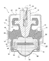
次に、図1に基づいて、本発明の実施形態を説明する。図1は、本実施形態におけるエンジンマウントの全体構成を示す断面図である。
図1に示すように、エンジンマウント(防振装置)10は、自動車における振動発生部であるエンジンを振動受け部である車体へ支持するものである。なお、以下の説明において、図中の符号Sはエンジンマウント10の軸心を示しており、この軸心Sに沿った方向をエンジンマウント10の軸方向とする。
Next, an embodiment of the present invention will be described with reference to FIG. FIG. 1 is a cross-sectional view showing the overall configuration of the engine mount in the present embodiment.
As shown in FIG. 1, an engine mount (anti-vibration device) 10 supports an engine that is a vibration generating unit in an automobile to a vehicle body that is a vibration receiving unit. In the following description, symbol S in the figure indicates the axis of the
エンジンマウント10は、筒状のブラケット金具12と、ブラケット金具12に内嵌固定された円筒形状の外筒金具(第1部材)14と、外筒金具14の内周側の上方に略同軸的に配置された内筒金具(第2部材)16と、外筒金具14と内筒金具16との間に配置されたゴム材料等からなる弾性体18とを備えている。
The
ブラケット金具12は筒状の部材であり、一方の開口部を閉塞するように頂板部42が配置されている。その頂板部42の中央部には内筒金具16の挿通孔43が形成されている。また、他方の開口部側には径方向外側に拡大した拡径部45が形成されている。ブラケット金具12の外周面には脚部材(不図示)が固着され、その脚部材がボルトを介して車体側に締結固定される。
The
外筒金具14には、上端部に円筒状の大径部28が形成されるとともに、下端側に大径部28に対して小径とされた円筒状の小径部30が形成されている。外筒金具14には、大径部28と小径部30との間に内周側へ縮径された絞り部32が全周に亘って形成されている。
A cylindrical large-
また、内筒金具16は砲弾形状の部材であって、その上部には軸心Sに沿って延びる連結部22が形成されている。この連結部22は、ブラケット金具12の挿通孔43に挿通されており、その中心部にねじ孔24が穿設されている。このねじ孔24にボルト26が捻じ込まれてエンジン側ブラケット(不図示)が固定され、内筒金具16はエンジン側ブラケットを介してエンジン側に締結固定される。一方、内筒金具16の下側には、下方に向けて先細るテーパ部21が形成されている。そして、連結部22とテーパ部21との間には、内筒金具16の径方向外側に張り出すアンカ部20が形成されている。
Further, the
弾性体18は、外周面が外筒金具14における大径部28及び絞り部32の内周側に加硫接着されるとともに、内周面が内筒金具16におけるテーパ部21の外周側に加硫接着されている。これにより、内筒金具16と外筒金具14とは弾性的に連結される。外筒金具14と内筒金具16との間には、内筒金具16におけるテーパ部21の周囲を囲んで弾性体18を貫通するインナーリング35が内装されている。また、弾性体18の内周面の上端部は、アンカ部20の外周を包み込むように延設され、ブラケット金具12とともにリバウンドストッパ機構が形成されている。一方、弾性体18の下側は、凹状に形成され、後述する主液室84と副液室86とが形成される液室形成領域34として構成されている。
The
外筒金具14の小径部30の内周側には、円筒形状のダイヤフラム支持部材80が嵌挿されている。
ここで、ダイヤフラム支持部材80の内周側には、ゴム等の弾性材料からなるダイヤフラム82が加硫接着されている。ダイヤフラム82は凸の椀状に形成され、軸心Sに沿って下方(液室形成領域34の外側)へ突出するように組み付けられている。ダイヤフラム支持部材80は、外筒金具14の小径部30を径方向内側にかしめることによって固定されている。これにより、液室形成領域34内が閉塞され、その内部には流体が封入される。なお、液室形成領域34内に充填される流体としては、エチレングリコール、水等が用いられる。
A cylindrical
Here, a
液室形成領域34内には、このダイヤフラム支持部材80と外筒金具14の絞り部32との間に挟持された仕切部材44が設けられている。
そして、仕切部材44を挟んで液室形成領域34の下側がダイヤフラム82により閉塞され、仕切部材44とダイヤフラム82との間に副液室86が形成されている。一方、仕切部材44を挟んで液室形成領域34の上側が弾性体18により閉塞され、弾性体18と仕切部材44との間に主液室84が形成される。
A
Then, the lower side of the liquid
仕切部材44は、その中央に環状のベース部56を備えている。このベース部56の開口部には、この開口部を閉塞するメンブラン75が張設されている。このメンブラン75は、ゴム等の弾性材料により撓み変形可能に構成されている。
The
ベース部56の外周側には、径方向外側に開口する断面視U字状のオリフィス溝59が、ベース部56を取り巻くように形成されている。このオリフィス溝59には、上面側に周方向に沿う一部が切除された上側連通孔61が形成されるとともに、下面側に周方向に沿う一部が切除された下側連通孔(不図示)が形成されている。また、上側連通孔61と下側連通孔との間におけるオリフィス溝59内には、このオリフィス溝59内を周方向に遮断する図示しない仕切り壁が形成されている。
On the outer peripheral side of the
そして、上述した仕切部材44のオリフィス溝59は、上側連通孔61を介して主液室84と連通するとともに、下側連通孔を介して副液室86に連通する。これにより、主液室84と副液室86とを互いに連通させる細長い通路であるオリフィス通路が形成されている。本実施形態のエンジンマウント10では、オリフィス溝59、上側連通孔61および下側連通孔からなるオリフィス通路によりシェイクオリフィス108が形成される。
The orifice groove 59 of the
なお、シェイクオリフィス108の路長及び断面積、すなわち流路抵抗は、車両における低周波域の共振振動であるシェイク振動の周波数(例えば、8Hz〜12Hz)に対応するように設定(チューニング)されている。
The path length and cross-sectional area of the
ここで、凸の椀状に形成されたダイヤフラム82は、エンジン重量による初期静荷重が入力される前、すなわち車体に取り付けられる前の状態で、副液室86の外側に向かって突出するように組み付けられている。そのため、初期静荷重の入力により主液室84から副液室86に流体が流入し、ダイヤフラム82が下方に膨張して張力が付与されるようになっている。そして、振動荷重の入力によりダイヤフラム82がさらに膨張して張力が増加するようになっている。
Here, the
具体的には、エンジンからの初期静荷重の入力によって、エンジンマウント10の内筒金具に下方に向かう力が作用し、吸振主体である弾性体18が弾性変形して主液室84を収縮させることで、主液室84内の流体がシェイクオリフィス108を通って副液室86へ流れ込む。これにより、副液室86を構成する撓み変形可能なダイヤフラム82が下方へ膨張することとなり、ダイヤフラム82には常に副液室86の内容積が復元する方向へ張力が付与された状態となる。
Specifically, when an initial static load is input from the engine, a downward force is applied to the inner cylinder fitting of the
また、本実施形態のエンジンマウント10は、初期静荷重の入力により主液室84から副液室86に流体が流入するように構成されているため、振動荷重入力時には確実にダイヤフラム82が膨張する。そのため、初期静荷重入力時に副液室から主液室に流体が流入する構成(いわゆる吊り下げ型)のエンジンマウントに比べて、ダイヤフラム82に張力が付与され易い構成となっている。
Further, since the
(作用)
次に、図1、2に基づいて本実施形態におけるエンジンマウント10の作用を説明する。ここで、図2はエンジンマウントのダイヤフラム膨張時を示す断面図であり、具体的にはエンジンマウントへ初期静荷重が入力された場合における断面図である。
エンジンマウント10ではエンジンまたは車体側からの振動荷重入力時に、弾性体18が弾性変形すると、その入力振動が弾性体18により遮断及び吸収されるようになっている。
(Function)
Next, the operation of the
In the
まず、入力振動の周波数がシェイク振動の周波数(例えば、8Hz〜12Hz)以下で、その振幅が相対的に大きい場合は、シェイクオリフィス108を通して主液室84と副液室86との間で流体が相互に流通する。
First, when the frequency of the input vibration is equal to or less than the frequency of the shake vibration (for example, 8 Hz to 12 Hz) and the amplitude is relatively large, the fluid flows between the main
シェイクオリフィス108は、その路長及び断面積がシェイク振動の周波数及び振幅に適合するようにチューニングされているため、入力振動が特にシェイク振動である場合には、シェイクオリフィス108を流通する流体に共振現象(液柱共振)が生じ、この液柱共振の作用によってシェイク振動を特に効果的に吸収できる。
また、入力振動の周波数がシェイク振動の周波数よりも高く、その振幅が小さい場合(例えば、入力振動がアイドル振動(例えば、20Hz〜40Hz)の場合)は、シェイク振動に適合するようにチューニングされたシェイクオリフィス108が目詰まり状態となり、シェイクオリフィス108には流体が流れ難くなる。この時、メンブラン75が入力振動に同期して振動することにより、主液室84内の液圧上昇を緩和することが可能になる。これにより、主液室84内の液圧上昇に伴う動ばね定数の上昇を緩和させ、低動倍化することができるので、アイドル振動のような中高周波振動も効果的に吸収することができる。
The
In addition, when the frequency of the input vibration is higher than the frequency of the shake vibration and the amplitude thereof is small (for example, when the input vibration is idle vibration (for example, 20 Hz to 40 Hz)), the frequency is tuned to match the shake vibration. The
なお、本実施形態において、シェイク振動やアイドル振動時のような振動荷重入力時には、上述したように既にダイヤフラム82は下方に向けて膨張し、その復元方向に張力が作用しているが、この時点でのダイヤフラム82の張力は微小であるため、張力による防振特性の低下は少ない。そのため、上述のようなシェイク振動やアイドル振動が入力された場合でも、各振動を効果的に吸収することができる。
In this embodiment, when a vibration load such as shake vibration or idle vibration is input, the
ところで、路面の凹凸等により大きなバウンド荷重が入力され、主液室84内の液圧が急激に上昇した後に、そのバウンド荷重に対するリバウンド荷重が入力されると、主液室84の液圧が負圧になることがある。主液室84内の液圧が負圧になると、主液室84内の流体中に多数の気泡が生成されるキャビテーションが発生する。
By the way, when a large bounce load is input due to road surface unevenness and the like, and the liquid pressure in the main
具体的には、上述のようなキャビテーションを起こしうる大きなバウンド荷重が作用し、内筒金具16が弾性体18とともに主液室84を収縮させることで、主液室84の内容積が縮小する。これにより、主液室84内の液圧が急激に上昇し、主液室84内の流体がシェイクオリフィス108内を通って副液室86へと大量に流れ込む。
流体が副液室86内に流れ込むと、副液室86の内容積が増加する。これにより、図2に示すように、ダイヤフラム82が下側に大きく膨張する。
Specifically, a large bouncing load that can cause cavitation as described above acts, and the inner cylinder fitting 16 contracts the main
When the fluid flows into the secondary
そして、エンジンマウント10には、バウンド荷重が作用した後に、そのバウンド荷重に対するリバウンド荷重が作用することとなる。
この時、ダイヤフラム82は初期静荷重により膨張して予め張力が付与されており、バウンド荷重によりさらに膨張して張力が増加している。そのため、副液室86内の液圧は正圧(大気圧以上)となっている。
これにより、主液室84から副液室86内に流れ込んだ流体が、再びシェイクオリフィス108を介して主液室84に流入しやすくなる。したがって、バウンド荷重の入力後にリバウンド荷重が入力される際に生じる主液室84内の急激な液圧変化を緩和することができるため、主液室84内が負圧になることを緩和することができる。
And after a bound load acts on the
At this time, the
As a result, the fluid that has flowed into the
上述の実施形態によれば、外筒金具14または内筒金具16に対して、初期静荷重に加え振動荷重が入力された場合に、ダイヤフラム82に張力が付与されるように形成されている構成とした。
この構成によれば、振動荷重が入力された場合に、ダイヤフラム82に張力が付与されるので、副液室86内の液圧が正圧(大気圧以上)になる。そのため、バウンド荷重の入力により主液室84から副液室86に流入した流体が、リバウンド荷重の入力時に再び主液室84に流入しやすくなる。これにより、キャビテーションを起こしうる大きなバウンド荷重に対するリバウンド荷重の入力時における主液室84内の急激な液圧低下を緩和することが可能になり、キャビテーションの発生を抑制することができる。
According to the above-described embodiment, the configuration is such that tension is applied to the
According to this configuration, when a vibration load is input, tension is applied to the
また、通常、副液室の内側に突出するように取り付けられるダイヤフラム82を、外側に突出するように取り付けることで、初期静荷重の入力のみによりダイヤフラム82を膨張させることが可能になり、ダイヤフラム82に張力を付与し易くなる。また、従来技術とはダイヤフラム82の組み付け方向を逆転させたものであり、従来のダイヤフラム82を流用して簡単に組立てることができる。
Further, the
なお、従来の流体封入式エンジンマウントの中には、ダイヤフラムを覆うカバー部材を備え、ダイヤフラムとカバー部材との間に密閉封止された空気室を有するものがあった。このエンジンマウントにおいて、バウンド荷重の入力により主液室から副液室に流体が流入すると、空気室内の空気が圧縮されて空気圧が上昇する。この空気圧の上昇に伴って、本発明と同様に副液室内の液圧が上昇することになる。これにより、本発明と同様にキャビテーションを抑制できることが実験で確認されている。
このような従来のエンジンマウントに対して、本発明ではダイヤフラム82の外側にカバー部材を別途に設ける必要もない。したがって、部品点数や組み付け工数を削減することができるため、製造コストを削減することができる。さらに、カバー部材の取付スペースを省くことができるため、エンジンマウント10の小型軽量化が可能になる。
Some conventional fluid-filled engine mounts include a cover member that covers the diaphragm, and an air chamber that is hermetically sealed between the diaphragm and the cover member. In this engine mount, when fluid flows from the main liquid chamber into the sub liquid chamber by the input of the bound load, the air in the air chamber is compressed and the air pressure rises. As the air pressure increases, the hydraulic pressure in the sub liquid chamber increases as in the present invention. Thus, it has been confirmed by experiments that cavitation can be suppressed as in the present invention.
In contrast to such a conventional engine mount, according to the present invention, it is not necessary to separately provide a cover member outside the
なお、本発明は上述の実施形態に限られるものではなく、本発明の趣旨を逸脱しない範囲において、上述の実施形態に種々の変更を加えたものを含む。
例えば、ダイヤフラムの形状は下方に向けた凸状に限らず、振動荷重入力時にダイヤフラムに張力が付与されるような形状であればよい。
The present invention is not limited to the above-described embodiment, and includes various modifications made to the above-described embodiment without departing from the spirit of the present invention.
For example, the shape of the diaphragm is not limited to a downward convex shape, and may be any shape that allows tension to be applied to the diaphragm when a vibration load is input.
また、ダイヤフラムには、少なくともキャビテーションを発生させる振動荷重入力時に張力が作用していればよく、エンジン等の重量による静荷重のみが作用している場合に張力が作用していなくてもよい。
また、本実施形態において、内筒金具をエンジン側に連結すると共に、外筒金具を車体側に連結したが、これとは逆に内筒金具を車体側に連結すると共に、外筒金具をエンジン側に連結するようにしてもよい。
Further, it is sufficient that tension is applied to the diaphragm at least when a vibration load for generating cavitation is input, and the tension may not be applied when only a static load due to the weight of the engine or the like is applied.
In the present embodiment, the inner cylinder fitting is connected to the engine side and the outer cylinder fitting is connected to the vehicle body side. On the contrary, the inner cylinder fitting is connected to the vehicle body side and the outer cylinder fitting is connected to the engine side. You may make it connect with the side.
製造コストを抑えた上で、キャビテーションの発生を抑制することができる。 The generation of cavitation can be suppressed while suppressing the manufacturing cost.
10 エンジンマウント(防振装置)
14 外筒金具(第1部材)
16 内筒金具(第2部材)
18 弾性体
44 仕切部材
84 主液室
86 副液室
108 シェイクオリフィス(オリフィス通路)
10 Engine mount (anti-vibration device)
14 Outer tube fitting (first member)
16 Inner tube bracket (second member)
18
Claims (1)
前記第1部材の内周側に配置されるとともに、振動発生部に連結され、前記振動発生部を下方から支持する第2部材と、
前記第1部材と前記第2部材との間を弾性的に連結するとともに、前記第2部材から前記第1部材に向かうに従い下方に向けて延在し、前記第1部材の一方の開口部を閉塞する弾性体と、
前記第1部材における他方の開口部を閉塞するダイヤフラムと、
前記第1部材の内部に封入された液体と、
前記第1部材の内部を、前記弾性体側の主液室および前記ダイヤフラム側の副液室に仕切る仕切部材と、
前記主液室と前記副液室とを互いに連通するオリフィス通路とを備えた防振装置において、
前記初期静荷重の入力により、前記主液室から前記副液室に前記液体が流入するように形成されるとともに、前記第2部材に対して、初期静荷重が入力された場合に、前記ダイヤフラムの全面に張力が付与され、
前記ダイヤフラムは、前記初期静荷重が入力される前の状態で、前記副液室の外側に向かって突出するように組み付けられていることを特徴とする防振装置。 A first member connected to the vibration receiving portion and formed in a cylindrical shape;
A second member disposed on an inner peripheral side of the first member, coupled to a vibration generating unit, and supporting the vibration generating unit from below;
While elastically connecting between the first member and the second member, and extending downward from the second member toward the first member, one opening of the first member An elastic body that closes;
A diaphragm for closing the other opening of the first member;
A liquid sealed inside the first member;
A partition member for partitioning the inside of the first member into a main liquid chamber on the elastic body side and a sub liquid chamber on the diaphragm side;
In the vibration isolator including an orifice passage that communicates the main liquid chamber and the sub liquid chamber with each other,
When the initial static load is input , the diaphragm is formed so that the liquid flows from the main liquid chamber into the sub liquid chamber, and when the initial static load is input to the second member, the diaphragm Tension is applied to the entire surface of
The anti-vibration device according to claim 1, wherein the diaphragm is assembled so as to protrude toward the outside of the auxiliary liquid chamber before the initial static load is input.
Priority Applications (5)
| Application Number | Priority Date | Filing Date | Title |
|---|---|---|---|
| JP2007183405A JP5210558B2 (en) | 2007-07-12 | 2007-07-12 | Vibration isolator |
| CN2008800240671A CN101688582B (en) | 2007-07-12 | 2008-07-10 | Vibration-proof device |
| PCT/JP2008/062478 WO2009008475A1 (en) | 2007-07-12 | 2008-07-10 | Vibration-proof device |
| US12/668,756 US20100187733A1 (en) | 2007-07-12 | 2008-07-10 | Anti-vibration device |
| EP08791036.0A EP2172670A4 (en) | 2007-07-12 | 2008-07-10 | Vibration-proof device |
Applications Claiming Priority (1)
| Application Number | Priority Date | Filing Date | Title |
|---|---|---|---|
| JP2007183405A JP5210558B2 (en) | 2007-07-12 | 2007-07-12 | Vibration isolator |
Publications (2)
| Publication Number | Publication Date |
|---|---|
| JP2009019709A JP2009019709A (en) | 2009-01-29 |
| JP5210558B2 true JP5210558B2 (en) | 2013-06-12 |
Family
ID=40228646
Family Applications (1)
| Application Number | Title | Priority Date | Filing Date |
|---|---|---|---|
| JP2007183405A Expired - Fee Related JP5210558B2 (en) | 2007-07-12 | 2007-07-12 | Vibration isolator |
Country Status (5)
| Country | Link |
|---|---|
| US (1) | US20100187733A1 (en) |
| EP (1) | EP2172670A4 (en) |
| JP (1) | JP5210558B2 (en) |
| CN (1) | CN101688582B (en) |
| WO (1) | WO2009008475A1 (en) |
Families Citing this family (8)
| Publication number | Priority date | Publication date | Assignee | Title |
|---|---|---|---|---|
| WO2009096378A1 (en) * | 2008-01-28 | 2009-08-06 | Bridgestone Corporation | Vibration-damping device |
| KR101041629B1 (en) | 2009-12-14 | 2011-06-16 | 주식회사 파브코 | Engine mount |
| JP6154243B2 (en) * | 2013-08-14 | 2017-06-28 | 山下ゴム株式会社 | Liquid seal mount |
| JP6395660B2 (en) | 2015-04-27 | 2018-09-26 | 株式会社ブリヂストン | Vibration isolator |
| CN105130998B (en) * | 2015-09-25 | 2017-07-28 | 苏州立新制药有限公司 | Ku Pannixi preparation method |
| EP3156686B1 (en) | 2015-10-12 | 2020-04-15 | Vibracoustic AG | Hydraulic mount, in particular for the suspension of a motor vehicle engine |
| US10788095B2 (en) * | 2017-06-26 | 2020-09-29 | Hrl Laboratories, Llc | Fluid and elastomer vibration isolator |
| JP6941524B2 (en) * | 2017-09-27 | 2021-09-29 | 本田技研工業株式会社 | Active vibration damping device |
Family Cites Families (11)
| Publication number | Priority date | Publication date | Assignee | Title |
|---|---|---|---|---|
| DE3225700C1 (en) * | 1982-07-09 | 1983-11-17 | Fa. Carl Freudenberg, 6940 Weinheim | Elastic rubber bearing |
| US4588173A (en) * | 1983-11-23 | 1986-05-13 | General Motors Corporation | Hydraulic-elastomeric mount |
| JPS6165932A (en) * | 1984-09-05 | 1986-04-04 | Bridgestone Corp | Anti-vibration device |
| JPH0694888B2 (en) * | 1990-04-11 | 1994-11-24 | 東海ゴム工業株式会社 | Fluid-filled mounting device |
| JP2914461B2 (en) | 1991-04-08 | 1999-06-28 | 株式会社ブリヂストン | Fluid filling method for vibration isolator |
| US5273262A (en) * | 1992-06-15 | 1993-12-28 | General Motors Corporation | Hydraulic mount with low amplitude, low-to-medium frequency vibration isolation |
| JP2005273906A (en) * | 2004-02-27 | 2005-10-06 | Tokai Rubber Ind Ltd | Liquid filled vibration damper |
| CN1697943A (en) * | 2004-04-08 | 2005-11-16 | 东洋橡胶工业株式会社 | Vibration isolation device |
| JP4069907B2 (en) * | 2004-06-30 | 2008-04-02 | 東海ゴム工業株式会社 | Liquid seal type vibration isolator with resin bracket |
| CN1701189A (en) * | 2004-10-12 | 2005-11-23 | 东洋橡胶工业株式会社 | Liquid sealing type anti-vibration apparatus |
| JP2007120566A (en) * | 2005-10-26 | 2007-05-17 | Bridgestone Corp | Vibration isolator |
-
2007
- 2007-07-12 JP JP2007183405A patent/JP5210558B2/en not_active Expired - Fee Related
-
2008
- 2008-07-10 US US12/668,756 patent/US20100187733A1/en not_active Abandoned
- 2008-07-10 WO PCT/JP2008/062478 patent/WO2009008475A1/en not_active Ceased
- 2008-07-10 EP EP08791036.0A patent/EP2172670A4/en not_active Withdrawn
- 2008-07-10 CN CN2008800240671A patent/CN101688582B/en active Active
Also Published As
| Publication number | Publication date |
|---|---|
| US20100187733A1 (en) | 2010-07-29 |
| JP2009019709A (en) | 2009-01-29 |
| WO2009008475A1 (en) | 2009-01-15 |
| EP2172670A4 (en) | 2015-05-13 |
| CN101688582A (en) | 2010-03-31 |
| CN101688582B (en) | 2012-07-04 |
| EP2172670A1 (en) | 2010-04-07 |
Similar Documents
| Publication | Publication Date | Title |
|---|---|---|
| JP4228219B2 (en) | Fluid filled vibration isolator | |
| JP4330437B2 (en) | Fluid filled vibration isolator | |
| JP5210558B2 (en) | Vibration isolator | |
| JP5557837B2 (en) | Vibration isolator | |
| JPWO2007116976A1 (en) | Vibration isolator | |
| JP2010031989A (en) | Fluid-sealed vibration control device | |
| JP4823976B2 (en) | Liquid filled anti-vibration support device | |
| JP2009103223A (en) | Vibration damper | |
| JP4494988B2 (en) | Liquid filled anti-vibration mount device | |
| JP4392667B2 (en) | Fluid filled vibration isolator | |
| JP2010048282A (en) | Vibration control device | |
| JP2009085252A (en) | Fluid sealed type vibration damper | |
| JP4088836B2 (en) | Fluid filled vibration isolator | |
| JP4238128B2 (en) | Vibration isolator | |
| JP2007271004A (en) | Fluid-sealed vibration isolating device | |
| JP5027093B2 (en) | Fluid filled vibration isolator | |
| JP5386289B2 (en) | Fluid filled vibration isolator | |
| JP4181163B2 (en) | Liquid-filled vibration isolator | |
| JP4328589B2 (en) | Vibration isolator | |
| JP2007270866A (en) | Fluid sealed vibration control device | |
| JP2006083980A (en) | Liquid encapsulating mount | |
| JP2011064258A (en) | Vibration control device | |
| JP2009191999A (en) | Vibration absorbing device | |
| JP2008249076A (en) | Fluid sealed type vibration damper | |
| JP2008196508A (en) | Fluid-sealed vibration isolating device |
Legal Events
| Date | Code | Title | Description |
|---|---|---|---|
| A621 | Written request for application examination |
Free format text: JAPANESE INTERMEDIATE CODE: A621 Effective date: 20100305 |
|
| A131 | Notification of reasons for refusal |
Free format text: JAPANESE INTERMEDIATE CODE: A131 Effective date: 20120417 |
|
| A521 | Written amendment |
Free format text: JAPANESE INTERMEDIATE CODE: A523 Effective date: 20120618 |
|
| A131 | Notification of reasons for refusal |
Free format text: JAPANESE INTERMEDIATE CODE: A131 Effective date: 20120710 |
|
| A521 | Written amendment |
Free format text: JAPANESE INTERMEDIATE CODE: A523 Effective date: 20120905 |
|
| A131 | Notification of reasons for refusal |
Free format text: JAPANESE INTERMEDIATE CODE: A131 Effective date: 20121106 |
|
| A521 | Written amendment |
Free format text: JAPANESE INTERMEDIATE CODE: A523 Effective date: 20121221 |
|
| TRDD | Decision of grant or rejection written | ||
| A01 | Written decision to grant a patent or to grant a registration (utility model) |
Free format text: JAPANESE INTERMEDIATE CODE: A01 Effective date: 20130129 |
|
| A61 | First payment of annual fees (during grant procedure) |
Free format text: JAPANESE INTERMEDIATE CODE: A61 Effective date: 20130225 |
|
| FPAY | Renewal fee payment (event date is renewal date of database) |
Free format text: PAYMENT UNTIL: 20160301 Year of fee payment: 3 |
|
| R150 | Certificate of patent or registration of utility model |
Ref document number: 5210558 Country of ref document: JP Free format text: JAPANESE INTERMEDIATE CODE: R150 Free format text: JAPANESE INTERMEDIATE CODE: R150 |
|
| R250 | Receipt of annual fees |
Free format text: JAPANESE INTERMEDIATE CODE: R250 |
|
| R250 | Receipt of annual fees |
Free format text: JAPANESE INTERMEDIATE CODE: R250 |
|
| R250 | Receipt of annual fees |
Free format text: JAPANESE INTERMEDIATE CODE: R250 |
|
| R250 | Receipt of annual fees |
Free format text: JAPANESE INTERMEDIATE CODE: R250 |
|
| R250 | Receipt of annual fees |
Free format text: JAPANESE INTERMEDIATE CODE: R250 |
|
| LAPS | Cancellation because of no payment of annual fees |