JP5196180B2 - Rolling bearing device with sensor - Google Patents
Rolling bearing device with sensor Download PDFInfo
- Publication number
- JP5196180B2 JP5196180B2 JP2009020485A JP2009020485A JP5196180B2 JP 5196180 B2 JP5196180 B2 JP 5196180B2 JP 2009020485 A JP2009020485 A JP 2009020485A JP 2009020485 A JP2009020485 A JP 2009020485A JP 5196180 B2 JP5196180 B2 JP 5196180B2
- Authority
- JP
- Japan
- Prior art keywords
- sensor
- holding member
- rolling bearing
- inner ring
- main body
- Prior art date
- Legal status (The legal status is an assumption and is not a legal conclusion. Google has not performed a legal analysis and makes no representation as to the accuracy of the status listed.)
- Expired - Fee Related
Links
Images


Classifications
-
- F—MECHANICAL ENGINEERING; LIGHTING; HEATING; WEAPONS; BLASTING
- F16—ENGINEERING ELEMENTS AND UNITS; GENERAL MEASURES FOR PRODUCING AND MAINTAINING EFFECTIVE FUNCTIONING OF MACHINES OR INSTALLATIONS; THERMAL INSULATION IN GENERAL
- F16C—SHAFTS; FLEXIBLE SHAFTS; ELEMENTS OR CRANKSHAFT MECHANISMS; ROTARY BODIES OTHER THAN GEARING ELEMENTS; BEARINGS
- F16C41/00—Other accessories, e.g. devices integrated in the bearing not relating to the bearing function as such
- F16C41/007—Encoders, e.g. parts with a plurality of alternating magnetic poles
-
- F—MECHANICAL ENGINEERING; LIGHTING; HEATING; WEAPONS; BLASTING
- F16—ENGINEERING ELEMENTS AND UNITS; GENERAL MEASURES FOR PRODUCING AND MAINTAINING EFFECTIVE FUNCTIONING OF MACHINES OR INSTALLATIONS; THERMAL INSULATION IN GENERAL
- F16C—SHAFTS; FLEXIBLE SHAFTS; ELEMENTS OR CRANKSHAFT MECHANISMS; ROTARY BODIES OTHER THAN GEARING ELEMENTS; BEARINGS
- F16C19/00—Bearings with rolling contact, for exclusively rotary movement
- F16C19/02—Bearings with rolling contact, for exclusively rotary movement with bearing balls essentially of the same size in one or more circular rows
- F16C19/14—Bearings with rolling contact, for exclusively rotary movement with bearing balls essentially of the same size in one or more circular rows for both radial and axial load
- F16C19/18—Bearings with rolling contact, for exclusively rotary movement with bearing balls essentially of the same size in one or more circular rows for both radial and axial load with two or more rows of balls
- F16C19/181—Bearings with rolling contact, for exclusively rotary movement with bearing balls essentially of the same size in one or more circular rows for both radial and axial load with two or more rows of balls with angular contact
- F16C19/183—Bearings with rolling contact, for exclusively rotary movement with bearing balls essentially of the same size in one or more circular rows for both radial and axial load with two or more rows of balls with angular contact with two rows at opposite angles
- F16C19/184—Bearings with rolling contact, for exclusively rotary movement with bearing balls essentially of the same size in one or more circular rows for both radial and axial load with two or more rows of balls with angular contact with two rows at opposite angles in O-arrangement
- F16C19/186—Bearings with rolling contact, for exclusively rotary movement with bearing balls essentially of the same size in one or more circular rows for both radial and axial load with two or more rows of balls with angular contact with two rows at opposite angles in O-arrangement with three raceways provided integrally on parts other than race rings, e.g. third generation hubs
-
- F—MECHANICAL ENGINEERING; LIGHTING; HEATING; WEAPONS; BLASTING
- F16—ENGINEERING ELEMENTS AND UNITS; GENERAL MEASURES FOR PRODUCING AND MAINTAINING EFFECTIVE FUNCTIONING OF MACHINES OR INSTALLATIONS; THERMAL INSULATION IN GENERAL
- F16C—SHAFTS; FLEXIBLE SHAFTS; ELEMENTS OR CRANKSHAFT MECHANISMS; ROTARY BODIES OTHER THAN GEARING ELEMENTS; BEARINGS
- F16C2326/00—Articles relating to transporting
- F16C2326/01—Parts of vehicles in general
- F16C2326/02—Wheel hubs or castors
-
- F—MECHANICAL ENGINEERING; LIGHTING; HEATING; WEAPONS; BLASTING
- F16—ENGINEERING ELEMENTS AND UNITS; GENERAL MEASURES FOR PRODUCING AND MAINTAINING EFFECTIVE FUNCTIONING OF MACHINES OR INSTALLATIONS; THERMAL INSULATION IN GENERAL
- F16C—SHAFTS; FLEXIBLE SHAFTS; ELEMENTS OR CRANKSHAFT MECHANISMS; ROTARY BODIES OTHER THAN GEARING ELEMENTS; BEARINGS
- F16C33/00—Parts of bearings; Special methods for making bearings or parts thereof
- F16C33/72—Sealings
- F16C33/76—Sealings of ball or roller bearings
- F16C33/78—Sealings of ball or roller bearings with a diaphragm, disc, or ring, with or without resilient members
- F16C33/7869—Sealings of ball or roller bearings with a diaphragm, disc, or ring, with or without resilient members mounted with a cylindrical portion to the inner surface of the outer race and having a radial portion extending inward
- F16C33/7879—Sealings of ball or roller bearings with a diaphragm, disc, or ring, with or without resilient members mounted with a cylindrical portion to the inner surface of the outer race and having a radial portion extending inward with a further sealing ring
- F16C33/7883—Sealings of ball or roller bearings with a diaphragm, disc, or ring, with or without resilient members mounted with a cylindrical portion to the inner surface of the outer race and having a radial portion extending inward with a further sealing ring mounted to the inner race and of generally L-shape, the two sealing rings defining a sealing with box-shaped cross-section
Landscapes
- Engineering & Computer Science (AREA)
- General Engineering & Computer Science (AREA)
- Mechanical Engineering (AREA)
- Rolling Contact Bearings (AREA)
Description
本発明は、センサ付き転がり軸受装置に関するものである。 The present invention relates to a rolling bearing device with a sensor.
一般に、車両(例えば、自動車)のハブユニット(転がり軸受装置)には、車輪の回転速度を検出するセンサ装置が取り付けられている。センサ装置は、例えば自動車のアンチロックブレーキシステム(ABS)の情報入力手段として用いられる。 In general, a sensor device that detects the rotational speed of a wheel is attached to a hub unit (rolling bearing device) of a vehicle (for example, an automobile). The sensor device is used, for example, as information input means for an anti-lock brake system (ABS) of an automobile.
センサ装置は、車輪を取り付けるハブ(内輪)と、このハブを回転自在に支持し、かつ車両固定部材に固定される外輪と、それらの間に介装される複数個の転動体とを備えた転がり軸受に取り付けられる。即ち、転がり軸受の内輪における車両インナ側の端面部には、センサ装置を構成する磁気エンコーダが固定される。また、外輪における車両インナ側の端部には、磁気エンコーダを被覆する環状のカバーが装着され、このカバーに、磁気エンコーダと対向配置されるABSセンサ(以下、センサという。)が取り付けられている。上記したセンサ装置のように、車輪の回転に伴って回転する磁気エンコーダの磁気変化を、センサによって検出するようにしたものが知られている(例えば、特許文献1を参照)。 The sensor device includes a hub (inner ring) to which wheels are attached, an outer ring that rotatably supports the hub and is fixed to a vehicle fixing member, and a plurality of rolling elements interposed therebetween. Mounted on a rolling bearing. That is, a magnetic encoder constituting the sensor device is fixed to an end surface portion on the vehicle inner side of the inner ring of the rolling bearing. In addition, an annular cover that covers the magnetic encoder is attached to an end of the outer ring on the vehicle inner side, and an ABS sensor (hereinafter referred to as a sensor) that is disposed to face the magnetic encoder is attached to the cover. . As described above, there is known a sensor device that detects a magnetic change of a magnetic encoder that rotates with the rotation of a wheel using a sensor (see, for example, Patent Document 1).
特許文献1に開示される技術では、センサをばね部材の弾性復元力で押圧することによってカバーに固定している。すると、センサ周辺部の熱変化や経時的なばね部材の押圧により、センサとカバーとの間でクリープが生じてセンサの固定力が低下し、センサの安定的な出力検知が困難になる場合がある。
In the technique disclosed in
また、例えば特許文献2に開示される技術のように、センサに突起部を設け、この突起部のねじ挿通孔を利用してボルト締結する場合、センサの全体形状が大きくなり、その占有空間が大きくなってしまう。
For example, as in the technique disclosed in
本発明は、上記した事情に鑑み、センサ付き転がり軸受装置において、センサの固定力を低下させることなく、該センサを小型化することを課題としている。 In view of the above circumstances, an object of the present invention is to downsize a sensor in a rolling bearing device with a sensor without reducing the fixing force of the sensor.
上記課題を達成するための本発明は、
車両インナ側の車両固定部材に接続される外輪と、車両アウタ側の車輪に接続される内輪と、前記内輪と前記外輪との間に介在される転動体と、前記内輪の回転数を検出するためのセンサ装置と、を備えるセンサ付き転がり軸受装置であって、
前記センサ装置は、前記内輪に固定され、周方向で磁気特性が交互に変化する円環状の磁気エンコーダと、該磁気エンコーダの回転による磁気変化を検出するセンサと、前記センサを前記磁気エンコーダと対向配置させるための保持部材と、を有し、
前記センサは、検出体が内装されたセンサ本体部と、前記センサ本体部の断面積よりも小さい断面積で該センサ本体部の一端部から延設される雄ねじ部と、を備え、
前記保持部材は、前記外輪に装着される円環状の第1保持部材と、該第1保持部材に固定され、前記センサを保持するための第2保持部材とで構成され、前記第2保持部材は、前記センサの雄ねじ部を通すねじ挿通孔が設けられた板状の取付部と、前記取付部の一端部から屈曲し、固定手段によって前記第1保持部材に固定されるステー部と、を備え、
前記センサは、その雄ねじ部が前記第2保持部材の取付部のねじ挿通孔に挿通され、そのセンサ本体部の一端部が前記取付部に突き当てられた状態で前記雄ねじ部にナットが締め込まれ、該ナットと前記センサ本体部が前記第2保持部材の取付部を挟み込むことによって保持されることを特徴としている。
The present invention for achieving the above-mentioned problems
An outer ring connected to a vehicle fixing member on the vehicle inner side, an inner ring connected to a wheel on the vehicle outer side, a rolling element interposed between the inner ring and the outer ring, and a rotational speed of the inner ring are detected. A sensor-equipped rolling bearing device comprising:
The sensor device includes an annular magnetic encoder that is fixed to the inner ring and whose magnetic characteristics alternately change in a circumferential direction, a sensor that detects a magnetic change caused by rotation of the magnetic encoder, and the sensor that faces the magnetic encoder. A holding member for arranging,
The sensor includes a sensor main body in which a detection body is internally provided, and a male screw portion extending from one end of the sensor main body with a cross-sectional area smaller than the cross-sectional area of the sensor main body,
The holding member includes an annular first holding member attached to the outer ring, and a second holding member fixed to the first holding member and holding the sensor, and the second holding member Includes a plate-like attachment portion provided with a screw insertion hole for passing the male screw portion of the sensor, and a stay portion bent from one end portion of the attachment portion and fixed to the first holding member by a fixing means. Prepared,
The sensor has a male screw portion inserted into a screw insertion hole of an attachment portion of the second holding member, and a nut is tightened into the male screw portion in a state where one end portion of the sensor main body portion is abutted against the attachment portion. Rarely, the nut and the sensor main body are held by sandwiching the mounting portion of the second holding member.
本発明に係る転がり軸受装置は、上記したように構成されていて、センサのセンサ本体部に設けられた雄ねじ部が、第2保持部材の取付部のねじ挿通孔に挿通された状態でナットが締め込まれることによって保持される。このため、従来のセンサ本体部に設けられ、取付け状態でラジアル方向又は周方向に突出する突起部が不要となり、全体形状が小型化される。また、センサは、取付部のねじ挿通孔に挿通された雄ねじ部にナットが締め込まれることによって第2保持部材に固定され、従来のようにセンサ本体部に押圧力が作用することはない。これにより、長期間に亘ってセンサの安定出力が確保される。 The rolling bearing device according to the present invention is configured as described above, and the nut is inserted in a state where the male screw portion provided in the sensor main body portion of the sensor is inserted into the screw insertion hole of the attachment portion of the second holding member. It is held by being tightened. For this reason, the protrusion part which is provided in the conventional sensor main-body part and protrudes in a radial direction or the circumferential direction in an attached state becomes unnecessary, and the whole shape is reduced in size. Further, the sensor is fixed to the second holding member by tightening the nut into the male screw portion inserted through the screw insertion hole of the attachment portion, and the pressing force does not act on the sensor main body portion as in the related art. Thereby, the stable output of a sensor is ensured over a long period of time.
前記第2保持部材の取付部のねじ挿通孔を、前記センサ装置の取付け状態におけるアキシャル方向に沿って長孔としてもよい。これにより、前記センサの取付け位置をアキシャル方向に調整可能とすることができる。 The screw insertion hole of the attachment portion of the second holding member may be a long hole along the axial direction in the attachment state of the sensor device. Thereby, the mounting position of the sensor can be adjusted in the axial direction.
また、前記第2保持部材の取付部におけるねじ挿通孔の長孔の一端部を切り欠いて、開口部を形成してもよい。これにより、センサを、ねじ挿通孔の開口部から挿入して第2保持部材に取り付けることができるため、取付け時の作業性が良好になる。 Moreover, you may cut out the one end part of the elongate hole of the screw penetration hole in the attaching part of a said 2nd holding member, and you may form an opening part. Thereby, since a sensor can be inserted from the opening part of a screw insertion hole and attached to a 2nd holding member, workability | operativity at the time of attachment becomes favorable.
以下、本発明の実施の形態について詳細に説明する。 Hereinafter, embodiments of the present invention will be described in detail.
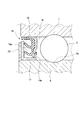
図1は本発明に係るセンサ付き転がり軸受装置100の取付け状態の断面図、図2はセンサ付き転がり軸受装置100の斜視図、図3は密封部材16の拡大断面図、図4は磁気エンコーダ22の斜視図、図5はセンサ装置21の拡大断面図である。
FIG. 1 is a cross-sectional view of a rolling bearing
図1及び図2に示されるように、センサ付き転がり軸受装置100(以下、転がり軸受装置100という。)は、軸受鋼材からなる固定輪としての外輪1と、回転輪としての内輪2と、外輪1と内輪2との間に介装され、複数列(本実施例の場合、2列)で配列される多数個の転動体3とから構成される転がり軸受4を備えている。
As shown in FIGS. 1 and 2, a sensor-equipped rolling bearing device 100 (hereinafter referred to as a rolling bearing device 100) includes an
内輪2はハブ5と一体に形成されている。ハブ5は、車両アウタ側(図1の図面視における右側)で車輪(図示せず)と接続して装着するために、外方へ突設される円盤状のハブフランジ6を備えている。このハブフランジ6は、ハブボルト7によって車輪に固定される。そして、ハブフランジ6は、内輪2の一端部(車両アウタ側の外周に一体形成されている。また、内輪2の他端部(車両インナ側。図1の図面視における右側)には、外径が小さくなった小径部が形成されている。この小径部には、別体で形成された内輪分割体8が圧入固定される。内輪分割体8の外周面には、複数列で配列される一方の転動体3を転動させるための転動面8aが形成されている。また、内輪8の外周面にも、複数列で配列される他方の転動体3が転動する転動面2aが形成されている。このように、小径部に内輪分割体8が圧入されて一体化されることによって、一端部にハブフランジ6を備えた内輪2が構成される。
The
内輪2の中心部分(軸線CLの部分)にはスプライン孔が形成されていて、このスプライン孔に動力を伝達する駆動軸としてのドライブシャフト9がスプライン結合されている。ドライブシャフト9は段付き軸であり、その段付き面(軸直角面)は内輪分割体8における車両インナ側の端面に当接している。そして、ドライブシャフト9の車両アウタ側の端部は、ハブ5から突出している。この突出部分にナット11が螺合されて締め込まれることにより、ドライブシャフト9がハブ5に固定される。
A spline hole is formed in the center portion of the inner ring 2 (the portion of the axis line CL), and a
転がり軸受装置100は、車両における懸架装置を構成するナックル、アクスルハウジングなどの車両固定部材12の端面部に接続される。この接続は、転がり軸受4の外輪1を車両固定部材12に挿入して嵌装させ、外輪1から外方へ突設される鍔部13を、ボルト14で車両固定部材12の端面部に固定させることによって行っている。
The rolling bearing
転がり軸受4は、外輪1と内輪2との間に介装された密封部材15,16により、水や泥などの異物が浸入しないようにされているとともに、転がり軸受4からグリースが漏れないように密封されている。これらの密封部材15,16は、外輪1におけるアキシャル方向の両端部に取り付けられている。例えば車両インナ側の密封部材16は、図3に示されるように、内輪分割体8の外周面に装着され、略L字状の断面を有する環状のスリンガ17と、外輪1の内周面にスリンガ17と対向して嵌装され、略L字状の断面を有する環状の芯金18とを備えている。芯金18には、ゴム状弾性体からなり、スリンガ17に接触して摺動するシール部材19が加硫接着されている。シール部材19から3本のリップ部19aが突出されていて、これらのリップ部19aが、スリンガ17に接触している。
The rolling bearing 4 is configured so that foreign matters such as water and mud are prevented from entering by sealing
図1及び図2に示されるように、転がり軸受4の車両インナ側の端部には、車輪の回転変化を検出するセンサ装置21が取り付られている。本実施例のセンサ装置21は、磁気エンコーダ22と、該磁気エンコーダ22の回転による磁気変化を検出するセンサ23と、該センサ23を取り付けるためのブラケット24(センサ固定部材。第2保持部材)と、該ブラケット24を固定するためのセンサ保持体25(第1保持部材)とを備えている。
As shown in FIGS. 1 and 2, a
図4に示されるように、磁気エンコーダ22は、円環状で、異なる極性の磁極(N極,S極)が周方向に交互に並んで形成されている。この磁気エンコーダ22は、車両インナ側の密封装置16のスリンガ17の外側面に固定されていて、内輪2とともに回転する(図3参照)。
As shown in FIG. 4, the
本実施例のセンサ装置21について説明する。内輪2が回転したときの磁気エンコーダ22の磁気変化は、センサ23によって検出される。図5及び図6に示されるように、センサ23は磁気エンコーダ22の回転による磁気変化を検出する検出体(図示せず)を樹脂モールドによってパッケージングして、その断面形状を矩形状となした角柱状のセンサ本体部26と、センサ本体部26の上端面に取り付けられ、センサ本体部26の上端面よりも大きな面積を有する円板状のプレート27と、該プレート27の上面からセンサ本体部26とほぼ同軸にして延設され、プレート27よりも小さな断面積を有する雄ねじ部28と、雄ねじ部28の上端部から延設される角柱状のセンサ支持部29とを備えている。センサ本体部26の下端部における左右の側面部には、センサ本体部26を、後述するセンサ保持体25のセンサ取付孔31に設けられたレール部31a(図7参照)に嵌合するためのレール溝部32が形成されている。なお、図6において、33はケーブルである。
The
ここで、従来のセンサは、センサ本体部26とセンサ支持部29のみを備え、センサ支持部26に取付け用の突起部34(図6において、破線で示す部分)が突出して設けられている。本実施例のセンサ23は、既存のセンサを利用するために該センサに設けられていた突起部34を切断し、その状態のセンサ本体部26に円板状のプレート27をモールドするとともに、その状態のセンサ支持部29に雄ねじ部28を有するスリーブをモールドしている。しかし、検出体をパッケージングするときに、プレート27と雄ねじ部28を一体に形成することが望ましい。これにより、プレート27と雄ねじ部28を有するスリーブのモールド加工が不要になる。
Here, the conventional sensor includes only the sensor
センサ23は、ブラケット24を介してセンサ保持体25に固定される。このブラケット24は、図5及び図6に示されるように、二股に形成された板部材(取付部35)と、その二股部分を略直角に折り曲げた一対のステー部36とを備えている。取付部35には、センサ23の雄ねじ部28の外径よりも大きな内幅を有する長孔35aが設けられている。この長孔35aにおける一端部(取付け状態における車両インナ側の端部)は切り欠かれていて、開口部(第1開口部37)が設けられている。また、一対のステー部36同士の間にも、センサ23のプレート27を挿入するための開口部(第2開口部38)が設けられている。当然のことながら第2開口部38の内幅は、センサ23のプレート27の外径よりも少し大きい。そして、各ステー部36の先端部は、いったん取付部35と平行になるように直角に屈曲され、更に各ステー部36の上部と平行になるように直角に屈曲され、階段状を呈している。一対のステー部36の先端部には、ブラケット24をセンサ保持体25に固定するための孔部36aが設けられている。センサ23はブラケット24に対し、そのプレート27がブラケット24の取付部35の下方に配置されるように第1及び第2の開口部37,38を通って差し込まれ、かつ雄ねじ部28がブラケット24の取付部35の長孔35aの部分に配置されるようにセットされる。そして、雄ねじ部28にナット39が螺合される。センサ23は、ナット39とプレート27がブラケット24の取付部35を挟み込むことにより、ブラケット24に一体に保持される。
The
次に、センサ保持体25について説明する。図5及び図7に示されるように、センサ保持体25は段付きの円環状で、転がり軸受4の外輪1に圧入されて装着される円筒部41と、円筒部41の一端部からラジアル方向の軸心側(軸線CLに向かう方向)に向かって屈曲し、密封部材16を覆う機能を有する密封部材被覆部42と、密封部材被覆部42の先端部からドライブシャフト9の外周面に沿うように屈曲して延設され、その外周面との間に僅かな隙間e(ラビリンス)を形成するラビリンス形成部43とを備えている。センサ保持体25の上半部における密封部材被覆部42の外周縁部には、背面側に屈曲する上側当接部44が、周方向に所定の角度をおいて2箇所に切欠き状態で設けられている。また、センサ保持体25の下半部における密封部材被覆部42の外周縁部には、背面側に屈曲する下側当接部45が、周方向に所定の角度をおいて2箇所に切欠き状態で設けられている。本実施例のセンサ保持体25の場合、上側当接部44は所定の弧長を有して円弧状に設けられている。そして、下側当接部45は、点状に設けられている点を除いて上側当接部44と同一構成であるため、本明細書では上側当接部44についてのみ説明する。
Next, the
図5及び図7に示されるように、上側当接部44は、円筒部41の途中の部分からラジアル方向の軸心側(軸線CLに向かう方向)に向かって屈曲し、外輪1の端面部に当接する鍔部46と、密封部材被覆部42の上端部からアキシャル方向に沿って屈曲し、鍔部46と連結する連結部47とを備えている。連結部47の内径dは、磁気エンコーダ22の外径Dよりも大きい。このため、上側当接部44が磁気エンコーダ22に影響を及ぼすことはない。そして、センサ保持体25の円筒部41が外輪1の外周面に圧入されたとき、上側当接部44の鍔部46が外輪1の端面に当接する。これにより、センサ保持体25がアキシャル方向に位置決めされる。この状態で、磁気エンコーダ22の端面から密封部材被覆部42までの間に、距離Lの空間部Qが形成される(図5参照)。この空間部Qの存在により、隙間e(ラビリンス)を越えて侵入する異物が堆積しにくくなり(換言すれば、異物が落下し易くなり)、当該異物が磁気エンコーダ22に悪影響を及ぼすおそれが小さくなる。
As shown in FIGS. 5 and 7, the upper abutting
取付け状態におけるセンサ保持体25の上端部には、センサ装置21を構成するブラケット24を取り付けるためのセンサ取付孔31が設けられている。このセンサ取付孔31は、密封部材被覆部42における外周縁部からラジアル方向の途中の部分にまで設けられており、その下部には、周方向に対向してせり出す一対のレール部31aが設けられている。センサ23(図6参照)は、そのセンサ本体部26の側面部に設けられた一対のレール溝部32が、一対のレール部31aに差し込まれることにより、アキシャル方向及び周方向に移動することが規制される。そして、密封部材被覆部42におけるセンサ取付孔31の下方には、周方向に所定の間隔をおいて一対のねじ孔部48が設けられている。一対のねじ孔部48同士の間隔は、ブラケット24における一対のステー部36の孔部36a同士の間隔と同じである。ブラケット24が、センサ保持体25のセンサ取付孔31の部分に配置される。ブラケット24における一対のステー部36に設けられた孔部36aにボルト49(図2参照)が挿通され、対応するねじ孔部48に螺合される。これにより、ブラケット24がセンサ保持体25に固定される。なお、ブラケット24とセンサ保持体25との固定は、溶接などによってもすることができる。
A
図5及び図7に示されるように、取付け状態におけるセンサ保持体25の下端部(センサ取付孔31と対向する部分)には、空間部Qと外部とを連通するためのドレン孔51が、円筒部41と密封部材被覆部42とに跨る形でそれらを切り欠いて形成されている。これにより、空間部Qに侵入した異物がドレン孔51から排出される。また、軸心(軸線CL)からドレン孔51におけるラジアル方向の切欠面51aまでの半径rは、軸心から磁気エンコーダ22の外周面までの半径Rよりも少し大きい(r>R)。これにより、センサ保持体25の下端部(ドレン孔51の部分)においても、磁気エンコーダ22の全面が被覆され、磁気エンコーダ22に異物が付着するおそれが小さくなる。この結果、磁気エンコーダ22の信頼性が向上する。
As shown in FIGS. 5 and 7, a
本実施例の転がり軸受装置100の作用について説明する。ハブ5を構成する外輪1と内輪2及び内輪分割体9との間に転動体3が複列に組み込まれて、転がり軸受4が形成される。そして、外輪1の外周面にセンサ保持体25が圧入される。センサ保持体25は、センサ取付孔31が上部に配置され、ドレン孔51が下部に配置されるように圧入される。
The effect | action of the rolling
センサ23におけるプレート27が、ブラケット24の第2開口部38を通って取付部35の下方に差し込まれ、同じく雄ねじ部28が、ブラケット24の第1開口部37を通って取付部35の長孔35aの部分に差し込まれる。そして、雄ねじ部28に螺合されたナット39が締め込まれる。センサ23は、プレート27とナット39がブラケット24の取付部35を挟み込むことにより、ブラケット24に一体に保持される。
The
従来のセンサの場合、センサ本体部26から突設した突起部34の挿通孔34a(図6参照)に挿通されたボルト(図示せず)によってブラケット24に固定されている。しかし、本実施例のセンサ23は、センサ支持部29に設けられた雄ねじ部28にナット39が螺合されることによってブラケット24に固定される。換言すれば、本実施例のセンサ23では突起部34が不要である。これにより、センサ23を小型化することができる。
In the case of a conventional sensor, the
図2及び図5に示されるように、センサ23を取り付けたブラケット24が、センサ保持体25に取り付けられる。即ち、ブラケット24が、センサ保持体25の上方からセンサ取付孔31に挿入されるように差し込まれる。そして、センサ本体部26の一対のレール溝部32が、対応するセンサ取付孔31のレール部31aに嵌合される。この状態で、ブラケット24の一対のステー部36の孔部36aと、センサ保持体25の密封部材被覆部42のねじ孔部48とが合致する。センサ保持体25の手前側からブラケット24の孔部36aにボルト49が挿通され、ねじ孔部48に螺合される。これにより、センサ23がブラケット24を介して、センサ保持体25に固定される。
As shown in FIGS. 2 and 5, the
図5に示されるように、外輪1にセンサ保持体25が圧入されたとき、センサ保持体25のラビリンス形成部43は、ドライブシャフト11の外周面から僅かな隙間eを介して配置される。この隙間eがラビリンス効果を奏するため、水や泥などの異物が侵入しにくい。そして、隙間eを越えて侵入した異物は、ドライブシャフト9の外周面を伝って落下し、ドレン孔51から外部に排出される。このため、磁気エンコーダ22に異物が付着するおそれは少ない。
As shown in FIG. 5, when the
ドライブシャフト9とセンサ保持体25におけるラビリンス形成部43との隙間eは、両者が接触しないことを条件として、できるだけ小さいことが望ましい(図5参照)。また、ラビリンス形成部43の傾斜角度αは、ドライブシャフト9の傾斜角度βと同一又はそれよりも大きいことが望ましい(α≧β)。これにより、効果的に異物の侵入を防止することができる。
The gap e between the
上記した実施例のセンサ装置21では、ブラケット24の取付部35の長孔35aは、取付け状態における車両インナ側の端部が切り欠かれている。しかし、図8に示される別実施例のブラケット52のように、長孔35aの車両アウタ側の端部を切り欠き、車両アウタ側からセンサ23を差し込むようにして取り付けてもよい。この場合、ステー部36の切欠き(第2開口部38)を小さくできるため、センサ23を異物から確実に保護することができる。
In the
本発明は、車両に搭載されるハブユニットに適用することができる。 The present invention can be applied to a hub unit mounted on a vehicle.
100 センサ付き転がり軸受装置
1 外輪
2 内輪
3 転動体
8 内輪分割体(内輪)
12 車両固定部材
21 センサ装置
22 磁気エンコーダ
23 センサ
24,52 ブラケット(第2保持部材)
25 センサ保持体(第1保持部材)
28 雄ねじ部
35 取付部
35a 長孔(ねじ挿通孔)
36 ステー部
37 第1開口部(開口部)
39 ナット
49 ボルト(固定手段)
100 Rolling bearing device with
12
25 Sensor holder (first holding member)
28
36
39
Claims (3)
前記センサ装置は、前記内輪に固定され、周方向で磁気特性が交互に変化する円環状の磁気エンコーダと、該磁気エンコーダの回転による磁気変化を検出するセンサと、前記センサを前記磁気エンコーダと対向配置させるための保持部材と、を有し、
前記センサは、検出体が内装されたセンサ本体部と、前記センサ本体部の断面積よりも小さい断面積で該センサ本体部の一端部から延設される雄ねじ部と、を備え、
前記保持部材は、前記外輪に装着される円環状の第1保持部材と、該第1保持部材に固定され、前記センサを保持するための第2保持部材とで構成され、前記第2保持部材は、前記センサの雄ねじ部を通すねじ挿通孔が設けられた板状の取付部と、前記取付部の一端部から屈曲し、固定手段によって前記第1保持部材に固定されるステー部と、を備え、
前記センサは、その雄ねじ部が前記第2保持部材の取付部のねじ挿通孔に挿通され、そのセンサ本体部の一端部が前記取付部に突き当てられた状態で前記雄ねじ部にナットが締め込まれ、該ナットと前記センサ本体部が前記第2保持部材の取付部を挟み込むことによって保持されることを特徴とするセンサ付き転がり軸受装置。 An outer ring connected to a vehicle fixing member on the vehicle inner side, an inner ring connected to a wheel on the vehicle outer side, a rolling element interposed between the inner ring and the outer ring, and a rotational speed of the inner ring are detected. A sensor-equipped rolling bearing device comprising:
The sensor device includes an annular magnetic encoder that is fixed to the inner ring and whose magnetic characteristics alternately change in a circumferential direction, a sensor that detects a magnetic change caused by rotation of the magnetic encoder, and the sensor that faces the magnetic encoder. A holding member for arranging,
The sensor includes a sensor main body in which a detection body is internally provided, and a male screw portion extending from one end of the sensor main body with a cross-sectional area smaller than the cross-sectional area of the sensor main body,
The holding member includes an annular first holding member attached to the outer ring, and a second holding member fixed to the first holding member and holding the sensor, and the second holding member Includes a plate-like attachment portion provided with a screw insertion hole for passing the male screw portion of the sensor, and a stay portion bent from one end portion of the attachment portion and fixed to the first holding member by a fixing means. Prepared,
The sensor has a male screw portion inserted into a screw insertion hole of an attachment portion of the second holding member, and a nut is tightened into the male screw portion in a state where one end portion of the sensor main body portion is abutted against the attachment portion. A rolling bearing device with a sensor, wherein the nut and the sensor main body are held by sandwiching an attachment portion of the second holding member.
前記センサの取付け位置がアキシャル方向に調整可能であることを特徴とする請求項1に記載のセンサ付き転がり軸受装置。 The screw insertion hole of the mounting portion of the second holding member is a long hole along the axial direction in the mounting state of the sensor device,
The rolling bearing device with a sensor according to claim 1, wherein an attachment position of the sensor is adjustable in an axial direction.
前記センサは、前記ねじ挿通孔の開口部から挿入されて前記第2保持部材に取り付けられることを特徴とする請求項2に記載のセンサ付き転がり軸受装置。 One end of the long hole of the screw insertion hole in the mounting portion of the second holding member is cut out to form an opening,
The rolling bearing device with a sensor according to claim 2, wherein the sensor is inserted from an opening of the screw insertion hole and attached to the second holding member.
Priority Applications (1)
| Application Number | Priority Date | Filing Date | Title |
|---|---|---|---|
| JP2009020485A JP5196180B2 (en) | 2009-01-30 | 2009-01-30 | Rolling bearing device with sensor |
Applications Claiming Priority (1)
| Application Number | Priority Date | Filing Date | Title |
|---|---|---|---|
| JP2009020485A JP5196180B2 (en) | 2009-01-30 | 2009-01-30 | Rolling bearing device with sensor |
Publications (2)
| Publication Number | Publication Date |
|---|---|
| JP2010175031A JP2010175031A (en) | 2010-08-12 |
| JP5196180B2 true JP5196180B2 (en) | 2013-05-15 |
Family
ID=42706193
Family Applications (1)
| Application Number | Title | Priority Date | Filing Date |
|---|---|---|---|
| JP2009020485A Expired - Fee Related JP5196180B2 (en) | 2009-01-30 | 2009-01-30 | Rolling bearing device with sensor |
Country Status (1)
| Country | Link |
|---|---|
| JP (1) | JP5196180B2 (en) |
Families Citing this family (2)
| Publication number | Priority date | Publication date | Assignee | Title |
|---|---|---|---|---|
| JP6490995B2 (en) | 2015-03-12 | 2019-03-27 | Ntn株式会社 | Wheel bearing device with rotation speed detector |
| DE102017213231A1 (en) * | 2016-08-26 | 2018-03-01 | Aktiebolaget Skf | Sensor unit for a bearing |
Family Cites Families (6)
| Publication number | Priority date | Publication date | Assignee | Title |
|---|---|---|---|---|
| JP3630261B2 (en) * | 1997-04-17 | 2005-03-16 | 三菱電機株式会社 | Detector mounting structure |
| JP2001208763A (en) * | 1999-11-15 | 2001-08-03 | Nsk Ltd | Rolling bearing unit with rotation speed detector |
| JP2004076789A (en) * | 2002-08-12 | 2004-03-11 | Ntn Corp | Rotation sensor mounting structure for wheel bearing device |
| JP2004263718A (en) * | 2003-02-03 | 2004-09-24 | Koyo Seiko Co Ltd | Rolling bearing device |
| JP2007085906A (en) * | 2005-09-22 | 2007-04-05 | Sumiden Electronics Kk | Mounting structure of rotation detecting sensor |
| DE102006033931A1 (en) * | 2006-07-21 | 2008-01-24 | Robert Bosch Gmbh | Rotating movements measuring device for wheel bearing of motor vehicle, has carrier exhibiting paramagnetic or diamagnetic metallic retaining ring, with which metallic connecting unit is locked at sensor module |
-
2009
- 2009-01-30 JP JP2009020485A patent/JP5196180B2/en not_active Expired - Fee Related
Also Published As
| Publication number | Publication date |
|---|---|
| JP2010175031A (en) | 2010-08-12 |
Similar Documents
| Publication | Publication Date | Title |
|---|---|---|
| JP5334287B2 (en) | Bearing seal | |
| US20090038414A1 (en) | Sensor-Equipped Bearing for Wheel | |
| US8021052B2 (en) | Sensor-equipped bearing for wheel | |
| EP1433621B1 (en) | Rolling bearing apparatus with sensor | |
| US7819026B2 (en) | Sensor-equipped wheel support bearing assembly | |
| WO2005078457A1 (en) | Bearing device with sensor | |
| JP2008175382A (en) | Rolling bearing unit for wheel support with rotational speed detector | |
| JP5196180B2 (en) | Rolling bearing device with sensor | |
| JP2010096217A (en) | Rolling bearing device | |
| US7336067B2 (en) | Sensor assembly, sealing device, and roller bearing apparatus for vehicles having integrated connector and ring | |
| JP4508704B2 (en) | Bearing device with sensor | |
| JP5166218B2 (en) | Rolling bearing device with sensor | |
| JP2005331429A (en) | Rolling bearing unit with encoder | |
| JP5067718B2 (en) | Rolling bearing device with sensor | |
| JP2010121639A (en) | Bearing device for wheel | |
| JP4258222B2 (en) | Sensor assembly, sealing device and rolling bearing device | |
| JP2007120560A (en) | Wheel bearing device | |
| JP5051017B2 (en) | Rolling bearing device with sensor | |
| JP4984251B2 (en) | Rolling bearing device with sensor | |
| JP2008247072A (en) | Wheel support device | |
| JP2007078615A (en) | Bearing with sensor for wheel | |
| JP4813889B2 (en) | Hub unit for driven wheels | |
| JP5035754B2 (en) | Rolling bearing device with sensor | |
| JP2006226488A (en) | Rolling bearing device with sensor | |
| JP4656917B2 (en) | Wheel bearing device with rotation speed detector |
Legal Events
| Date | Code | Title | Description |
|---|---|---|---|
| A621 | Written request for application examination |
Free format text: JAPANESE INTERMEDIATE CODE: A621 Effective date: 20111223 |
|
| RD02 | Notification of acceptance of power of attorney |
Free format text: JAPANESE INTERMEDIATE CODE: A7422 Effective date: 20121012 |
|
| A977 | Report on retrieval |
Free format text: JAPANESE INTERMEDIATE CODE: A971007 Effective date: 20121203 |
|
| TRDD | Decision of grant or rejection written | ||
| A01 | Written decision to grant a patent or to grant a registration (utility model) |
Free format text: JAPANESE INTERMEDIATE CODE: A01 Effective date: 20130109 |
|
| A61 | First payment of annual fees (during grant procedure) |
Free format text: JAPANESE INTERMEDIATE CODE: A61 Effective date: 20130122 |
|
| FPAY | Renewal fee payment (event date is renewal date of database) |
Free format text: PAYMENT UNTIL: 20160215 Year of fee payment: 3 |
|
| R150 | Certificate of patent or registration of utility model |
Free format text: JAPANESE INTERMEDIATE CODE: R150 |
|
| LAPS | Cancellation because of no payment of annual fees |