JP5187007B2 - Image forming apparatus, display control method, and display control program - Google Patents
Image forming apparatus, display control method, and display control program Download PDFInfo
- Publication number
- JP5187007B2 JP5187007B2 JP2008148213A JP2008148213A JP5187007B2 JP 5187007 B2 JP5187007 B2 JP 5187007B2 JP 2008148213 A JP2008148213 A JP 2008148213A JP 2008148213 A JP2008148213 A JP 2008148213A JP 5187007 B2 JP5187007 B2 JP 5187007B2
- Authority
- JP
- Japan
- Prior art keywords
- display
- component
- screen
- setting
- request
- Prior art date
- Legal status (The legal status is an assumption and is not a legal conclusion. Google has not performed a legal analysis and makes no representation as to the accuracy of the status listed.)
- Expired - Fee Related
Links
Images


Classifications
-
- H—ELECTRICITY
- H04—ELECTRIC COMMUNICATION TECHNIQUE
- H04N—PICTORIAL COMMUNICATION, e.g. TELEVISION
- H04N1/00—Scanning, transmission or reproduction of documents or the like, e.g. facsimile transmission; Details thereof
- H04N1/0035—User-machine interface; Control console
- H04N1/00405—Output means
- H04N1/00408—Display of information to the user, e.g. menus
- H04N1/00464—Display of information to the user, e.g. menus using browsers, i.e. interfaces based on mark-up languages
-
- H—ELECTRICITY
- H04—ELECTRIC COMMUNICATION TECHNIQUE
- H04N—PICTORIAL COMMUNICATION, e.g. TELEVISION
- H04N1/00—Scanning, transmission or reproduction of documents or the like, e.g. facsimile transmission; Details thereof
- H04N1/32—Circuits or arrangements for control or supervision between transmitter and receiver or between image input and image output device, e.g. between a still-image camera and its memory or between a still-image camera and a printer device
- H04N1/32561—Circuits or arrangements for control or supervision between transmitter and receiver or between image input and image output device, e.g. between a still-image camera and its memory or between a still-image camera and a printer device using a programmed control device, e.g. a microprocessor
- H04N1/32593—Using a plurality of controllers, e.g. for controlling different interfaces
Landscapes
- Engineering & Computer Science (AREA)
- Multimedia (AREA)
- Signal Processing (AREA)
- Computer Hardware Design (AREA)
- Microelectronics & Electronic Packaging (AREA)
- Human Computer Interaction (AREA)
- Controls And Circuits For Display Device (AREA)
- Facsimiles In General (AREA)
- Accessory Devices And Overall Control Thereof (AREA)
- User Interface Of Digital Computer (AREA)
Description
本発明は、表示装置を備えた画像形成装置に係り、特に、当該画像形成装置が有する機能の操作画面(UI画面)を表示装置に表示する技術に関するものである。 The present invention relates to an image forming apparatus provided with a display device, and more particularly to a technique for displaying an operation screen (UI screen) for functions of the image forming device on the display device.
コピー、プリンタ、ファクシミリ、スキャナといった複数のアプリケーションを有する画像形成装置では、機能設定を行うためのGUI(Graphical User Interface)や、機能動作に関する情報などを表示する機能単位の表示画面(アプリケーション画面)を有し、当該画像形成装置の動作状態やユーザ要求に応じて、これらの画面を表示装置に表示するウィンドウシステムを搭載しており、当該画像形成装置が備える表示装置の高機能化が進んでいる。 In an image forming apparatus having a plurality of applications such as a copy, a printer, a facsimile, and a scanner, a GUI (Graphical User Interface) for performing function settings and a function unit display screen (application screen) for displaying information related to function operations are provided. And a window system for displaying these screens on the display device in accordance with the operating state of the image forming apparatus and a user request. The display device included in the image forming apparatus is becoming more sophisticated. .
このような画像形成装置では、例えば特許文献1に開示されるような、複数のグラフィックパーツ(以下、「表示部品」という。)からなる高機能な操作画面を表示することができる。特許文献1には、端末表示アプリと端末エミュレータとを搭載し、ソフトウェアキーボードなどのGUIを、当該画像形成装置が備える表示装置に表示する画像形成装置が提案されている。
しかしながら、従来の画像形成装置では、以下に挙げる問題点がある。 However, the conventional image forming apparatus has the following problems.
特許文献1に開示される従来の画像形成装置300では、図17に示すようなソフトウェアを搭載し、各種機能を実現している。その中で、表示装置を制御するソフトウェアが、サービスコントロール310に実装されたOCS(Operation panel Control System)311である。OCS311は、画像形成装置300が備えるコントローラ(非図示)上で動作し、主にユーザ操作の受け付け処理や、アプリケーション320に実装された各種アプリに対応する画面を表示するための描画処理などを行う。
A conventional
そのため、アプリケーション320は、OCS311が提供する描画関数をコールすることで、表示装置に画面を表示させることになる。
Therefore, the
そのため、機能が切り替わったときなど、その都度、切り替わったアプリケーション320が、描画関数をコールして画面を表示させなければならないことから、アプリケーション320実行時の処理に負荷がかかり、ユーザの使用感に悪影響を与えてしまう。
Therefore, each time the function is switched, the switched
また、従来の画像形成装置300では、表示装置に画面を表示するために、アプリケーション320の各機能を実現するプログラムを、表示内容や画面レイアウトに対応させて、必要な描画関数をコールするようにカスタマイズしなければならない。
Further, in the conventional
そのため、例えば表示内容や画面レイアウトに影響するような機能仕様の変更などに対応する場合、その作業は開発者にとって煩雑なものとなる。また、他のソフトウェアベンダ(以下、「サードベンダ」という。)などによる機能提供を、容易に行うことができない。 For this reason, for example, when dealing with changes in functional specifications that affect the display content and screen layout, the work becomes complicated for the developer. In addition, functions cannot be easily provided by other software vendors (hereinafter referred to as “third vendors”).
さらには、各機能の表示画面において表示される表示部品(例えば[OK]ボタンや[キャンセル]ボタン)を、ソフトウェア資源として効率よく管理することができない。 Furthermore, display components (for example, [OK] button or [Cancel] button) displayed on the display screen of each function cannot be efficiently managed as software resources.
本発明では、上記従来技術の問題点を鑑み、表示画面のカスタマイズを容易に行うことができる画像形成装置、表示制御方法、及び表示制御プログラムを提供することを目的とする。 In the present invention, in view of the problems of the prior art, an image forming apparatus which can be easily customized display screen, and to provide a table示制control method, and a display control program.
上記目的を達成するため、本発明の画像形成装置は、当該画像形成装置に関する情報画面や操作画面を表示する表示装置と、当該画像形成装置全体を制御する制御装置とを備える画像形成装置であって、前記制御装置が、前記表示装置に画面の表示要求を行う画面表示要求手段を有し、前記表示装置が、前記画面表示要求手段による画面表示要求を受け付ける画面表示要求受付手段と、前記画面表示要求受付手段により受け付けた画面表示要求に応じて、画面に表示させる表示部品を作成する表示部品作成手段と、前記表示部品作成手段により作成された表示部品を描画する表示部品描画手段とを有することを特徴とする。 In order to achieve the above object, an image forming apparatus of the present invention is an image forming apparatus including a display device that displays an information screen and an operation screen related to the image forming device, and a control device that controls the entire image forming device. The control device has screen display request means for requesting the display device to display a screen, and the display device accepts a screen display request by the screen display request means, and the screen In response to the screen display request received by the display request receiving unit, the display component creating unit creates a display component to be displayed on the screen, and the display component drawing unit draws the display component created by the display component creating unit. It is characterized by that.
このような構成によって、本発明の画像形成装置は、コントローラで動作する提供機能(アプリケーション)が、操作パネルに画面表示要求を行い、操作パネルで動作する表示部品作成機能が、要求時に指定された表示部品を作成し、描画機能が、作成された表示部品を描画した後に画面に表示する。 With this configuration, in the image forming apparatus of the present invention, the providing function (application) that operates on the controller makes a screen display request to the operation panel, and the display component creation function that operates on the operation panel is designated at the time of the request. A display component is created, and the drawing function draws the created display component and displays it on the screen.
また、上記目的を達成するため、本発明の画像形成装置は、前記制御装置が、画面に表示させる表示部品を指定する指定情報が定義された表示要求データを生成する表示要求データ生成手段を有し、前記画面表示要求手段が、前記表示要求データ生成手段により生成された表示要求データを、前記表示装置に送信し、画面の表示要求を行うことを特徴とする。 In order to achieve the above object, the image forming apparatus of the present invention includes a display request data generation unit that generates display request data in which designation information for designating display components to be displayed on the screen is defined by the control device. The screen display requesting unit transmits the display request data generated by the display request data generating unit to the display device and makes a screen display request.
また、上記目的を達成するため、本発明の画像形成装置は、前記画面表示要求受付手段が、前記制御装置から送信される前記表示要求データ生成手段により生成された表示要求データを取得し、画面表示要求を受け付けることを特徴とする。 In order to achieve the above object, in the image forming apparatus of the present invention, the screen display request receiving unit acquires the display request data generated by the display request data generating unit transmitted from the control device, and A display request is accepted.
また、上記目的を達成するため、本発明の画像形成装置は、前記表示装置が、前記画面表示要求受付手段により画面表示要求を受け付けたときに取得した表示要求データを構文解析し、前記表示要求データに定義された指定情報を取得する表示部品指定情報取得手段を有し、前記表示部品作成手段が、前記表示部品指定情報取得手段により取得された指定情報に基づいて、画面に表示させる表示部品を作成することを特徴とする。 In order to achieve the above object, the image forming apparatus of the present invention parses the display request data acquired when the display device receives a screen display request by the screen display request receiving unit, and Display component specifying information acquiring means for acquiring specified information defined in the data, and the display component creating means displaying on the screen based on the specified information acquired by the display component specifying information acquiring means It is characterized by creating.
また、上記目的を達成するため、本発明の画像形成装置は、前記表示装置が、前記表示部品を構成する構成部品における設定項目の設定候補値を保持する設定候補値保持手段を有し、前記表示部品作成手段が、前記表示部品指定情報取得手段により取得された指定情報と、前記設定候補値保持手段により保持しておいた設定候補値とに基づき、前記構成部品を生成し、前記表示部品を作成することを特徴とする。 In order to achieve the above object, in the image forming apparatus of the present invention, the display device includes setting candidate value holding means for holding setting candidate values of setting items in the component parts constituting the display part, The display component creating unit generates the component based on the designation information acquired by the display component designation information acquisition unit and the setting candidate value held by the setting candidate value holding unit, and the display component It is characterized by creating.
また、上記目的を達成するため、本発明の画像形成装置は、前記表示部品作成手段が、前記表示部品指定情報取得手段により取得された指定情報に基づいて、前記設定候補値保持手段により保持しておいた複数の設定候補値の中から、前記構成部品の設定項目に設定する設定値を特定し、特定した設定値を前記設定項目に設定した構成部品を生成することを特徴とする。 In order to achieve the above object, in the image forming apparatus of the present invention, the display component creation unit holds the setting candidate value holding unit based on the designation information acquired by the display component designation information acquisition unit. A setting value to be set for the setting item of the component is identified from a plurality of setting candidate values, and a component having the identified setting value set as the setting item is generated.
また、上記目的を達成するため、本発明の画像形成装置は、前記表示装置が、画面に表示される表示部品の設定変更要求を受け付ける設定変更要求受付手段を有し、前記表示部品作成手段が、前記設定変更要求受付手段により受け付けた設定変更要求に応じて、前記表示部品を構成する構成部品における設定項目の設定値を変更することを特徴とする。 In order to achieve the above object, in the image forming apparatus of the present invention, the display device includes a setting change request receiving unit that receives a setting change request for a display component displayed on a screen, and the display component creating unit includes: The setting value of the setting item in the component constituting the display component is changed according to the setting change request received by the setting change request receiving means.
また、上記目的を達成するため、本発明の画像形成装置は、前記表示部品描画手段が、前記表示部品作成手段により作成された表示部品を構成する各構成部品を描画することを特徴とする。 In order to achieve the above object, the image forming apparatus according to the present invention is characterized in that the display component drawing means draws each component constituting the display component created by the display component creating means.
これによって、本発明の画像形成装置は、従来、コントローラ側で動作する提供機能(アプリケーション)が行っていた描画処理を、操作パネル側で行うことにより、画面表示に関する処理において、画面表示要求を行う提供機能(アプリケーション)と表示画面を描画する描画機能とを独立させたソフトウェア構成とすることができ、表示画面のカスタマイズ時に行っていた提供機能(アプリケーション)を実現するプログラムの変更などを行うことなく、容易に表示画面のカスタマイズを行うことができる。 As a result, the image forming apparatus according to the present invention makes a screen display request in processing related to screen display by performing drawing processing, which has conventionally been performed by a providing function (application) operating on the controller side, on the operation panel side. It is possible to have a software configuration in which the provided function (application) and the drawing function that draws the display screen are independent, without changing the program that implements the provided function (application) that was used when customizing the display screen. The display screen can be easily customized.
上記目的を達成するため、本発明の表示装置は、当該表示装置が接続される機器に関する情報画面や機器の操作画面を表示する表示装置であって、前記機器からの画面表示要求を受け付ける画面表示要求受付手段と、前記替画面表示要求受付手段により受け付けた画面表示要求に応じて、画面に表示させる表示部品を作成する表示部品作成手段と、前記表示部品作成手段により作成された表示部品を描画する表示部品描画手段とを有することを特徴とする。 In order to achieve the above object, a display device of the present invention is a display device that displays an information screen related to a device to which the display device is connected and an operation screen of the device, and is a screen display that accepts a screen display request from the device. In response to the screen display request received by the replacement screen display request receiving means, a display component creating means for creating a display component to be displayed on the screen, and a display component created by the display component creating means are rendered. And display component drawing means.
また、上記目的を達成するため、本発明の表示装置は、前記画面表示要求受付手段が、前記機器から送信される、画面に表示させる表示部品を指定する指定情報が定義された表示要求データを取得し、画面表示要求を受け付けることを特徴とする。 In order to achieve the above object, in the display device of the present invention, the screen display request receiving unit transmits display request data in which designation information for designating display components to be displayed on the screen is transmitted from the device. Obtaining and accepting a screen display request.
また、上記目的を達成するため、本発明の表示装置は、前記画面表示要求受付手段により画面表示要求を受け付けたときに取得した表示要求データを構文解析し、前記表示要求データに定義された指定情報を取得する表示部品指定情報取得手段を有し、前記表示部品作成手段が、前記表示部品指定情報取得手段により取得された指定情報に基づいて、画面に表示させる表示部品を作成することを特徴とする。 In order to achieve the above object, the display device of the present invention parses the display request data acquired when the screen display request is received by the screen display request receiving means, and designates the display request data defined in the display request data. Display component designation information acquisition means for acquiring information, wherein the display component creation means creates a display component to be displayed on the screen based on the designation information acquired by the display component designation information acquisition means And
また、上記目的を達成するため、本発明の表示装置は、前記表示部品を構成する構成部品における設定項目の設定候補値を保持する設定候補値保持手段を有し、前記表示部品作成手段が、前記表示部品指定情報取得手段により取得された指定情報と、前記設定候補値保持手段により保持しておいた設定候補値とに基づき、前記構成部品を生成し、前記表示部品を作成することを特徴とする。 In order to achieve the above object, the display device of the present invention has setting candidate value holding means for holding setting candidate value of setting items in the constituent parts constituting the display part, and the display part creating means includes: The component is generated based on the designation information acquired by the display component designation information acquisition unit and the setting candidate value held by the setting candidate value holding unit, and the display component is created. And
また、上記目的を達成するため、本発明の表示装置は、前記表示部品作成手段が、前記表示部品指定情報取得手段により取得された指定情報に基づいて、前記設定候補値保持手段により保持しておいた複数の設定候補値の中から、前記構成部品の設定項目に設定する設定値を特定し、特定した設定値を前記設定項目に設定した構成部品を生成することを特徴とする。 In order to achieve the above object, in the display device of the present invention, the display component creation unit holds the setting candidate value holding unit based on the designation information acquired by the display component designation information acquisition unit. A setting value to be set for the setting item of the component is specified from a plurality of setting candidate values, and a component having the specified setting value set for the setting item is generated.
また、上記目的を達成するため、本発明の表示装置は、画面に表示される表示部品の設定変更要求を受け付ける設定変更要求受付手段を有し、前記表示部品作成手段が、前記設定変更要求受付手段により受け付けた設定変更要求に応じて、前記表示部品を構成する構成部品における設定項目の設定値を変更することを特徴とする。 In order to achieve the above object, the display device of the present invention includes a setting change request receiving unit that receives a setting change request for a display component displayed on the screen, and the display component creating unit receives the setting change request. In accordance with a setting change request received by the means, the setting value of the setting item in the component constituting the display component is changed.
また、上記目的を達成するため、本発明の表示装置は、前記表示部品描画手段が、前記表示部品作成手段により作成された表示部品を構成する各構成部品を描画することを特徴とする。 In order to achieve the above object, the display device of the present invention is characterized in that the display component drawing means draws each component constituting the display component created by the display component creating means.
このような構成によって、本発明の表示装置は、画面表示要求を受け付けたときに指定された表示部品の特徴(例えば表示形態(見た目)など)に基づいて、表示部品を構成する構成部品の設定項目を設定し、表示部品を生成するとともに、描画機能が、生成された表示部品を描画し、画面に表示する。 With such a configuration, the display device according to the present invention sets the components constituting the display component based on the characteristics (for example, display form (appearance)) of the display component designated when the screen display request is received. In addition to setting items and generating display components, the drawing function draws the generated display components and displays them on the screen.
これによって、本発明の表示装置は、サードベンダが提供する機能を含む提供機能(アプリケーション)からの簡便な画面表示要求を実現することができる。 Thus, the display device of the present invention can realize a simple screen display request from a provided function (application) including a function provided by a third vendor.
上記目的を達成するため、本発明の画像形成装置における表示制御方法は、当該画像形成装置に関する情報画面や操作画面を表示する表示装置と、当該画像形成装置全体を制御する制御装置とを備える画像形成装置における表示制御方法であって、前記制御装置から前記表示装置に画面の表示要求を行う画面表示要求手順と、前記画面表示要求手順による画面表示要求を受け付ける画面表示要求受付手順と、前記画面表示要求受付手順により受け付けた画面表示要求に応じて、画面に表示させる表示部品を作成する表示部品作成手順と、前記表示部品作成手順により作成された表示部品を描画する表示部品描画手順とを有することを特徴とする。 In order to achieve the above object, a display control method in an image forming apparatus of the present invention is an image including a display device that displays an information screen and an operation screen related to the image forming device, and a control device that controls the entire image forming device. A display control method in a forming apparatus, comprising: a screen display request procedure for requesting display of a screen from the control device to the display device; a screen display request reception procedure for receiving a screen display request according to the screen display request procedure; and the screen A display component creation procedure for creating a display component to be displayed on the screen in response to a screen display request accepted by the display request acceptance procedure, and a display component drawing procedure for drawing the display component created by the display component creation procedure It is characterized by that.
このような手順によって、本発明の画像形成装置における表示制御方法は、コントローラで動作する提供機能(アプリケーション)が、操作パネルに画面表示要求を行い、操作パネルで動作する表示部品作成機能が、要求時に指定された表示部品を作成し、描画機能が、作成された表示部品を描画した後に画面に表示する表示制御動作を実現する。 By such a procedure, the display control method in the image forming apparatus according to the present invention is such that the providing function (application) operating on the controller makes a screen display request to the operation panel, and the display component creation function operating on the operation panel is requested. A display component designated at times is created, and the drawing function realizes a display control operation of drawing the created display component and displaying it on the screen.
これによって、本発明の画像形成装置における表示制御方法は、表示画面のカスタマイズを容易に行える画像形成装置を提供できる。 Thus, the display control method in the image forming apparatus of the present invention can provide an image forming apparatus that can easily customize the display screen.
上記目的を達成するため、本発明の表示装置における表示制御方法は、当該表示装置が接続される機器に関する情報画面や機器の操作画面を表示する表示装置における表示制御方法であって、前記機器からの画面表示要求を受け付ける画面表示要求受付手順と、前記画面表示要求受付手順により受け付けた画面表示要求に応じて、画面に表示させる表示部品を作成する表示部品作成手順と、前記表示部品作成手順により作成された表示部品を描画する表示部品描画手順とを有することを特徴とする。 In order to achieve the above object, a display control method in a display device of the present invention is a display control method in a display device that displays an information screen related to a device to which the display device is connected and an operation screen of the device. A screen display request receiving procedure for receiving the screen display request, a display component creating procedure for creating a display component to be displayed on the screen according to the screen display request received by the screen display request receiving procedure, and the display component creating procedure. A display component drawing procedure for drawing the created display component.
このような手順によって、本発明の表示装置における表示制御方法は、画面表示要求を受け付けたときに指定された表示部品の特徴(例えば表示形態(見た目)など)に基づいて、表示部品を構成する構成部品の設定項目を設定し、表示部品を生成するとともに、描画機能が、生成された表示部品を描画し、画面に表示する表示制御動作を実現する。 By such a procedure, the display control method in the display device of the present invention configures the display component based on the characteristics (for example, display form (appearance)) of the display component specified when the screen display request is received. The setting items of the component parts are set to generate the display parts, and the drawing function realizes a display control operation for drawing the generated display parts and displaying them on the screen.
これによって、本発明の表示装置における表示制御方法は、サードベンダが提供する機能を含む提供機能(アプリケーション)からの簡便な画面表示要求を実現可能な表示装置を提供できる。 Thereby, the display control method in the display device of the present invention can provide a display device capable of realizing a simple screen display request from a providing function (application) including a function provided by a third vendor.
上記目的を達成するため、本発明の画像形成装置における表示制御プログラムは、当該画像形成装置に関する情報画面や操作画面を表示する表示装置と、当該画像形成装置全体を制御する制御装置とを備える画像形成装置における表示制御プログラムであって、コンピュータを、前記制御装置から前記表示装置に画面の表示要求を行う画面表示要求手段と、前記画面表示要求手段による画面表示要求を受け付ける画面表示要求受付手段と、前記画面表示要求受付手段により受け付けた画面表示要求に応じて、画面に表示させる表示部品を作成する表示部品作成手段と、前記表示部品作成手段により作成された表示部品を描画する表示部品描画手段として機能する。 In order to achieve the above object, a display control program in an image forming apparatus of the present invention is an image including a display device that displays an information screen and an operation screen related to the image forming device, and a control device that controls the entire image forming device. A display control program in a forming apparatus, comprising: a computer, a screen display request unit that requests a screen display from the control device to the display device; and a screen display request reception unit that receives a screen display request by the screen display request unit; In response to the screen display request received by the screen display request receiving means, display component creating means for creating a display component to be displayed on the screen, and display component drawing means for rendering the display component created by the display component creating means Function as.
上記目的を達成するため、本発明の表示装置における表示制御プログラムは、当該表示装置が接続される機器に関する情報画面や機器の操作画面を表示する表示装置における表示制御プログラムであって、コンピュータを、前記機器からの画面表示要求を受け付ける画面表示要求受付手段と、前記画面表示要求受付手段により受け付けた画面表示要求に応じて、画面に表示させる表示部品を作成する表示部品作成手段と、前記表示部品作成手段により作成された表示部品を描画する表示部品描画手段として機能する。 In order to achieve the above object, a display control program in a display device of the present invention is a display control program in a display device that displays an information screen related to a device to which the display device is connected and an operation screen of the device. Screen display request accepting means for accepting a screen display request from the device, display part creating means for creating a display part to be displayed on the screen in response to the screen display request accepted by the screen display request accepting means, and the display component It functions as display component drawing means for drawing the display component created by the creation means.
本発明によれば、表示画面のカスタマイズを容易に行うことができ、拡張性に優れた表示・操作環境を提供することができる。 According to the present invention, it is possible to easily customize a display screen and provide a display / operation environment excellent in expandability.
以下、本発明の好適な実施の形態(以下、「実施形態」という。)について、図面を用いて詳細に説明する。 DESCRIPTION OF EMBODIMENTS Hereinafter, preferred embodiments of the present invention (hereinafter referred to as “embodiments”) will be described in detail with reference to the drawings.
[第1の実施形態]
では、本実施形態に係る画像形成装置と、画像形成装置が備える表示装置である操作パネルのハードウェア構成について説明する。
[First Embodiment]
The hardware configuration of the image forming apparatus according to the present embodiment and the operation panel that is a display device included in the image forming apparatus will be described.
[画像形成装置]
図1は、本発明の第1の実施形態に係る画像形成装置100のハードウェア構成例を示す図である。画像形成装置100は、操作パネル110と、記憶メディアI/F120と、コントローラ130と、データ通信I/F140と、HDD(Hard Disk Drive)150と、スキャナ160と、プロッタ170とから構成され、それぞれバスで相互に接続されている。
[Image forming apparatus]
FIG. 1 is a diagram illustrating a hardware configuration example of an
操作パネル120は、入力部と表示部とを有しており、入力部は、ハードウェアキーなどで構成され、画像形成装置100に各操作信号を入力するのに用いられる。また、表示部は、ディスプレイなどで構成され、例えばユーザ操作を受け付けるGUIや画像形成動作に関する各種情報を表示する。データ通信I/F140は、インタフェース部を有しており、画像形成装置100をネットワークなどのデータ伝送路(非図示)に接続するインタフェースである。
The
HDD150は、画像形成装置100で取り扱われる受信文書データや読み取り画像データなどの各種データを格納している。また、HDD150は、これらの各種データを、所定のファイルシステムやDB(Data Base)により管理している。
The
上記HDD150に格納される各種データの中には、例えば、デジタルカメラなどの外部機器によって記録された電子データも含まれる。このような場合には、メモリカードなどの記録媒体121によって画像形成装置100に提供されるか、データ伝送路であるネットワークなどを通じてアップロードされる。記録媒体121は、記憶メディアI/F120にセットされ、各種データがHDD150へ格納される。
The various data stored in the
コントローラ130は、ROM(Read Only Memory)131、RAM(Random Access Memory)132、及びCPU(Central Processing Unit)133を備えており、画像形成装置全体の動作制御を行う。
The
ROM131には、各種プログラムや関連データが格納されており、各種プログラムには、例えば、画像形成装置100の全体を動作制御するプログラムや、画像形成装置100が有する機能を実現するプログラムなどがある。これらのプログラムは、RAM132に読み出され、CPU133により実行される。例えば、データ通信I/F140を介して印刷データを受信した場合に、ROM131からRAM132に読み出されたPDL(Page Description Language)を解釈可能なプリンタ機能を実現するプログラム(PDL パーサ)をCPU133により実行し、印刷データを解釈してビットマップイメージを生成する。
Various programs and related data are stored in the
スキャナ160は、画像読取部を有しており、読み取り面に載置された原稿を光学的に読み取り画像データを生成する。プロッタ170は、印刷部を有しており、例えば、電子写真プロセス方式によってビットマップイメージを用紙に印刷する。
The scanner 160 has an image reading unit, and optically reads a document placed on a reading surface and generates image data. The
[操作パネル(表示装置)]
図2は、本発明の第1の実施形態に係る操作パネル110のハードウェア構成例を示す図である。図2に示すように、操作パネル110の制御基板P上には、画像形成装置100の本体制御基板であるコントローラ130が備えるCPU133とは独立した専用のCPU1が搭載されており、操作パネル制御と本体制御は、同期シリアルなどの通信手段11(例えば「USB:Universal Serial Bus」など)により接続され、本体側からの表示要求や、操作パネル側からのキー入力情報などの双方向データ通信が可能な構成となっている。
[Operation panel (display device)]
FIG. 2 is a diagram illustrating a hardware configuration example of the
CPU1には、表示処理と入力処理に関する各種プログラムや関連データなどが格納されているROM2と、ワーク領域として使用されるRAM3とが接続されている。さらに、LCD(Liquid Crystal Display)モジュール6を制御するLCDコントローラ4、LCDモジュール6の表示画面に載置されるタッチパネル7、キー基板8のドライバ9などが接続されている。
Connected to the
また、CPU1は、LCDコントローラ4を介して、LCDモジュール6への表示画素データが格納されるビデオRAM、略してVRAMと呼ばれるSDRAM(Synchronous DRAM)5への読み/書きが可能であり、ドライバ9の先にあるキー基板8上のキースイッチ(SW)やLED(Light Emitting Diode)、LCDモジュール6のバックライト制御も可能である。
Further, the
LCDコントローラ4では、SDRAM5のリフレッシュ処理や、SDRAM5からLCDモジュール6への表示データ転送(表示信号出力)を行うが、内部レジスタへの設定により、この信号の出力が抑制可能となっている。 The LCD controller 4 performs refresh processing of the SDRAM 5 and transfer of display data (display signal output) from the SDRAM 5 to the LCD module 6. The output of this signal can be suppressed by setting the internal register.
また、LCDコントローラ4は、タッチパネルI/F機能も有しており、タッチパネル7が押下(タッチ)されると、LCDコントローラ4からCPU1に割り込み信号が送出される。
The LCD controller 4 also has a touch panel I / F function. When the touch panel 7 is pressed (touched), an interrupt signal is sent from the LCD controller 4 to the
さらに、操作パネル110の制御基板Pには、IC(Integrated Circuit)カードなどの記録媒体(例えば「フラッシュメモリ」など)の接続手段(例えば「カードスロット」など)が付加された、記録媒体からのデータ読み込みが可能な構成であってもよい。このとき、接続手段は、ICカード装着/未装着を入力ポートにて確認可能である。
Further, a connection means (for example, “card slot”, etc.) of a recording medium (for example, “flash memory”, etc.) such as an IC (Integrated Circuit) card is added to the control board P of the
以上のように、画像形成装置100では、上記ハードウェア構成により、コピー、プリンタ、ファクシミリ、スキャナなどの各種機能を実現するとともに、機能設定や動作条件設定などを受け付けるGUIや、動作情報、機器状態情報、ジョブ情報などを通知する画面を、操作パネル110に表示することができる。
As described above, the
<ソフトウェア構成>
近年では、画像形成装置100においても、装置に搭載する組み込みOS(Embedded Operating System)に、FreeBSDやLinuxといったUNIX系のOSを採用しているものも多い。このような動作環境の変化に伴い、画像形成装置100が備える操作パネル110への画面表示機能に、動作が非常に軽くハードウェアリソースを浪費しないことなどから、アドビシステムズ社が開発・提供する「Flash(登録商標)Player」を、1つのアプリケーションとして搭載し、多種多様な画面表示を実現している。この技術は、家電機器などといった独自機器への組み込み向けに"Flash Player SDK"などの開発キットがアドビシステムズ社から提供され、機器の用途に応じた開発を行うことができる。
<Software configuration>
In recent years, the
上記を踏まえて、画像形成装置100に搭載されるソフトウェアについて説明する。図3は、本発明の第1の実施形態に係る画像形成装置100のソフトウェア構成例を示す図である。
Based on the above, software installed in the
(コントローラ側に搭載されるソフトウェア構成)
画像形成装置100の本体制御を行うコントローラ130では、前述したOS21上で、Java(登録商標)言語によって定義された命令セットを実行する仮想マシンであるJavaVM22が動作する構成となっている。
(Software configuration installed on the controller side)
In the
JavaVM22は、Javaベースのサービスプラットフォームで動作するアプリケーションの標準構造を実装するために使用されるライブラリを提供するOSGi(Open Services Gateway initiative)フレームワーク23を有している。
The
上記OSGiフレームワーク23に基づき、通信24a、オペレーティング管理24b、セキュリティ24cといった各種OSGi提供サービス群24や、画像処理に関するデバイスサービス25などを実現するソフトウェアが動作している。
Based on the
また、JavaVM22上には、アプリケーションが使用するデータ26が保持され、さらに、コピー、プリンタ、ファクシミリ、スキャナなどの画像形成装置100の提供機能27を実現するソフトウェア(アプリケーション)と、これらの提供機能27とデータをやり取りするためのサービスインタフェース28を実現するソフトウェアインタフェースとが動作している。
Further, data used by the application is stored on the
提供機能27とサービスインタフェース28とは、直接JavaVM22上で動作する他、OSGi フレームワーク23を介してJavaVM22上で動作することも可能である。
The providing
このような構成により、例えば、サードベンダが、OSGi フレームワーク23を基に新たな機能(拡張機能)を簡便に開発・提供することが可能となる。さらに、このようにして提供された機能は、サービスインタフェース28を介して、他の機能とデータのやり取りを行うことができる。
With such a configuration, for example, a third vendor can easily develop and provide a new function (extended function) based on the
また、サービスインタフェース28には、XML(Extensible Markup Language)などの構造化言語により記述されたデータをやり取りするための仕組みを有している。本実施形態では、XMLデータをやり取りする場合の一例として、XMLデータを生成するXML ジェネレータ29aと、XMLデータを構文解析し解釈するXML パーサ29bとを有している例が示されている。
The
本実施形態では、上記サービスインタフェース28により、コントローラ130で動作する提供機能27のソフトウェアと、後述する操作パネル110が搭載するソフトウェアとが、XMLデータをやり取り(送受信)することができる。
In the present embodiment, the
(操作パネル側に搭載されるソフトウェア構成)
続いて、画像形成装置100が備える操作パネル110では、前述したOS31上で、ブラウザ32といった情報閲覧ソフトウェアや、前述したFlash プレーヤ33などの描画ソフトウェアが動作する構成となっている。
(Software configuration installed on the operation panel side)
Subsequently, the
Flash プレーヤ33は、Flashを再生し、その結果を画面に表示する。その際、各種コンテンツの再生は、ActionScript(アクションスクリプト)と言われるスクリプト言語に基づき、どのように再生するのかが制御される。このようにして、Flash プレーヤ33は、テキスト、静止画、音声、動画などの各種コンテンツを描画する。
The
さらにFlash プレーヤ33では、前述したXMLデータを解釈可能で、ブラウザ32のプラグインとして動作することも可能である。
Further, the
本実施形態では、上記Flash プレーヤ33が、前述したコントローラ130で動作する提供機能27のソフトウェアとXMLデータのやり取りを行う。
In this embodiment, the
ここまでは、画像形成装置100が備えるコントローラ130と操作パネル110それぞれのソフトウェア構成全般について説明を行った。以降には、その中でも、前述した「コントローラ130で動作する提供機能27のソフトウェアと、操作パネル110で動作する描画ソフトウェア(Flashプレーヤ33)とが、XMLデータをやり取り(送受信)する」処理について、画面表示処理を例に具体的に説明する。
Up to this point, the overall software configurations of the
《処理手順例》
図4は、画面表示時にコントローラ130と操作パネル110との間で行われる処理手順例を示すシーケンス図である。図4(A)には、従来における画像表示時の処理手順例、また図(B)には、本実施形態に係る画像表示時の処理手順例が示されている。
《Processing procedure example》
FIG. 4 is a sequence diagram illustrating an example of a processing procedure performed between the
(従来の処理手順)
コントローラ130で動作するアプリケーション320(提供機能27)が、OCS311の描画関数をコールし、機能に対応する画面を描画する(ステップS101)。その描画処理の中で、操作パネル110が解釈可能な制御コマンドを送信し、操作パネル110へ画面の表示を指示する(ステップS102)。
(Conventional procedure)
The application 320 (providing function 27) operating on the
その結果、操作パネル110は、受信した制御コマンドを処理し、LCDモジュール6の画面に描画結果を表示する(ステップS103)。
As a result, the
(本実施形態の処理手順)
コントローラ130で動作する提供機能27(アプリケーション320)が、サービスインタフェース28を介してXMLデータを送信し、操作パネル110へ機能に対応する画面の表示を要求する(ステップS201)。
(Processing procedure of this embodiment)
The providing function 27 (application 320) operating on the
その結果、操作パネル110は、表示要求としてXMLデータを受信し、データ内に指定された表示部品やその構成、また配置場所や表示形態(見た目)などに関する情報に基づき、描画ソフトウェアが描画し(ステップS202)、LCDモジュール6の画面に描画結果を表示する(ステップS203)。表示された結果は、要求元の提供機能27へXMLデータで応答される。
As a result, the
以上のように、従来では、コントローラ130の提供機能27によって描画処理を行っていたが、本実施形態では、操作パネル110の描画ソフトウェアによって行う構成となっている。
As described above, drawing processing is conventionally performed by the providing
そのため、コントローラ130の提供機能27では、表示する表示部品やその構成、また配置場所や表示形態(見た目)などの表示部品の特徴を指定するだけで、操作パネル110に画面を表示させることが可能となり、処理負荷を軽減することができ、さらに、画面表示処理との依存関係がないことから、開発者が煩雑な作業を行わなくても、容易に機能追加・拡張を行うことができる。
For this reason, the providing
また、従来では、提供機能27ごとに管理していた表示部品を、操作パネル110で一括管理することが可能となり、保守(メンテナンス)を容易に行うことができる。
Conventionally, display components managed for each provided
このように、本実施形態に係る画像形成装置100では、前述したコントローラ130と操作パネル110との間で行う画面表示処理により、提供機能27ごとの画面を、容易に表示することができる。
As described above, in the
なお、前述したソフトウェア構成において、コントローラ130と操作パネル110との間でサービスインタフェース28を介してやり取りを行うデータをXMLデータ、さらに、描画ソフトウェアを、Flashプレーヤ33を例に説明を行ったが、これに本発明が限定されるものではない。前述した表示画面処理に示すように、やり取りを行うデータと描画ソフトウェアとには、やり取りされるデータを描画ソフトウェアが解釈可能であるという関係がある。よって、この条件を満たしていればよい。以降の説明では、便宜上、XMLデータとFlash プレーヤ33とを用いて説明する。
In the above-described software configuration, the data exchanged between the
また、前述したソフトウェア構成において、サービス群24や提供機能27などのソフトウェアが動作する環境を、JavaVM22(OSGiフレームワーク23を含む)を例に説明を行ったが、これに本発明が限定されるものではない。コントローラ130からは表示要求を行い、操作パネル110で描画・表示処理を行う動作環境であればよい。以降の説明では、便宜上、JavaVM22を用いて説明する。
In the above-described software configuration, the environment in which software such as the service group 24 and the providing
《コンテンツ構成例》
ここからは、前述した操作パネル110において、描画処理を行うFlash プレーヤ33が再生する、Flashのコンテンツ構成(描画ソフトウェア上で動作するコンテンツ構成)について説明する。
《Content configuration example》
Hereafter, a description will be given of a Flash content configuration (a content configuration that operates on the rendering software) that is played back by the
(全体構成)
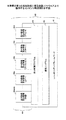
図5は、本発明の第1の実施形態に係る描画ソフトウェア上で動作するコンテンツ構成例を示す図である。Flash プレーヤ33で動作するコンテンツ40は、前述したように、画像形成装置100の搭載機能ごとの操作・情報通知画面を表示するためのソフトウェア部品群である。よって、コンテンツ40には、操作画面の標準構造を実装するために使用されるライブラリを提供するフレームワークであるLocalUIコンテンツフレームワーク41を有している。
(overall structure)
FIG. 5 is a diagram showing a content configuration example that operates on the drawing software according to the first embodiment of the present invention. As described above, the
コンテンツ40は、LocalUIコンテンツフレームワーク41に基づき、コントローラ130と操作パネル110との間でXMLデータをやり取りする通信プログラム42と、コントローラ130から受信したXMLデータに指定される表示部品やその構成、また配置場所や表示形態などに関する情報に基づき、搭載機能ごとの画面表示を制御する表示制御プログラム43とから構成される。上記通信プログラム42と上記表示制御プログラム43は、前述したActionScriptにより記述されたプログラムである。
The
さらに、コンテンツ40は、表示内容(テキストデータ)や背景画像(画像データ)、また実行指示や選択指示を受け付ける操作ボタンなどの配置場所(座標データ)を含むテンプレートや表示形態(色や形状などの見た目指定データ)である可視情報などの表示部品を作成するときに設定する表示部品設定情報群44を含んでいる。表示部品設定情報群44は、主に、搭載機能が画面を構成するときに共通して使用する共通部品の設定情報44comと、各搭載機能が画面構成するときに、それぞれにおいて使用する機能依存部品の設定情報44a〜dとから構成される。図5には、画像形成装置100が有するコピー、ファクシミリ、スキャナ、プリンタといった各機能に対応する機能依存部品設定情報群44a〜dを有している例が示されている。
Further, the
例えば表示部品が操作ボタンの場合、共通部品には、[OK]や[キャンセル]ボタン、数字やアルファベットといったソフトウェアキーなどがある。また、機能依存部品には、コピー機能の[部数設定]ボタン、ファクシミリ機能の[短縮ダイヤル]ボタン、スキャナ機能の[解像度設定]ボタン、プリンタ機能の[ジョブキャンセル]ボタンなどがある。 For example, when the display component is an operation button, common components include [OK] and [Cancel] buttons, software keys such as numbers and alphabets, and the like. The function-dependent parts include a “copy setting” button for the copy function, a “speed dial” button for the facsimile function, a “resolution setting” button for the scanner function, and a “job cancel” button for the printer function.
搭載機能ごとの画面は、表示部品の配置場所や表示形態(見た目)が異なることから、搭載機能ごとに使用する表示部品を作成するにあたって必要な各種設定候補値(表示部品設定情報)を予め所定のデータとして用意しておく(コンテンツ40に含めておく)。 Since the screen for each mounted function has different display component placement locations and display forms (looks), various setting candidate values (display component setting information) necessary for creating a display component to be used for each mounted function are determined in advance. Data is prepared (included in the content 40).
このように、搭載機能ごとに予め表示部品を構成する構成部品を生成するための複数の設定候補値を用意しておくことで、画面表示要求時に、表示部品の色や形状といった表示形態(見た目)などの大まかな特徴を指定するだけで、画面表示させたい表示部品を作成指示できる。すなわち、簡便に画面表示要求を行うことができる。 In this way, by preparing a plurality of setting candidate values for generating a component that constitutes a display component for each mounted function in advance, when a screen display request is made, a display form (appearance such as the color and shape of the display component) You can create a display component that you want to display on the screen simply by specifying a rough feature. That is, a screen display request can be made simply.
(表示部品の構造)
では、表示部品が、どのようなデータ構造をしており、かつどのような設定が可能であるか(どのような設定項目を有しているのか)について説明する。図6は、本発明の第1の実施形態に係る表示部品81の基本構造例を示す図である。
(Structure of display parts)
Now, what kind of data structure the display component has and what settings can be made (what setting items it has) will be described. FIG. 6 is a diagram showing an example of the basic structure of the
表示部品81は、部品の部品配置や表示形態(見た目)などを設定可能な(設定項目(属性項目)を有する)複数のレイヤ(構成部品)から構成される1つのMovieClipの構造をもつ。すなわち、図6に示すように、表示部品81は、表示部品81そのものを示すpartsMC810と、表示部品81の構成部品である各種レイヤにあたるMovieClipのBackground811、Template812、Image813、Graphics814、Clip815、及びText816、並びにsub-partsMC817とで構成される。
The
以下に、表示部品81そのものを示すpartsMC810と、partsMC810を親とする各構成部品について順に説明する。
Below, partsMC810 which shows
・partsMC
partsMC810は、各レイヤ(子にあたるMovieClip)をまとめるMovieClip(親にあたるMovieClip)であり、表示部品81に関する情報である部品情報を管理する。
・ PartsMC
The
・バックグラウンドレイヤ
Background811は、表示部品81の可視部分(表示形態:見た目)を設定するレイヤ(深度値:0)である。例えば、ボタンやアイコンの色や、画像やウィンドウの背景色などの単色塗りによるグラフィックスを設定可能である。さらにアニメーションなどの設定も可能である。
・ Background layer
・テンプレートレイヤ
バックグラウンドレイヤの上には、表示部品81と同じ構造をもつ部品(図中の"Template"に接続される"sub-partMC")を階層的に配置可能(MovieClip階層が可能)である。このことから、Template812は、部品の配置場所(階層構造における子にあたるMovieClip(下層部品)の接続場所)を設定するレイヤ(深度値:1)である。表示部品81は、このTemplate812上に配置された構成部品であるMovieClipに接続する。
-Template layer Parts that have the same structure as the display part 81 ("sub-partMC" connected to "Template" in the figure) can be arranged hierarchically on the background layer (MovieClip hierarchy is possible) is there. Thus, the
・イメージレイヤ
テンプレーレイヤの上に位置するImage813は、画像ファイルを読み込み、表示部品81に画像を表示するレイヤ(深度値:2)である。Image813では、画像の回転、変倍、移動を設定可能で、表示時に回転や変倍、また移動が必要な画像ファイルなどを設定できる。画像ファイル(例えばビットマップデータやJPEGデータなど)の他にも、画像の代替として使用する単色塗りによるグラフィックスを設定可能である。
・グラフィックスレイヤ
Graphics814は、表示部品81上にグラフィックスを表示するレイヤ(深度値:3)である。Graphics814には、描画するグラフィックスを設定可能である。
・ Graphics layer
・クリップレイヤ
Clip815は、表示部品81の部品領域を決定するレイヤ(深度値:4)である。Clip815には、表示部品81が決められた領域(部品領域)をはみ出さないようにクリップ(切り取り範囲領域)を設定可能である。
・ Clip layer
・テキストレイヤ
Text816は、表示部品81上に文字列を表示するレイヤ(深度値:5)である。Text816には、描画する文字列を設定可能で、さらに文字列を分割(図中の"Text1"〜"TextN")して設定することも可能である。このときの分割単位は、イメージ文字列のイメージ部分と文字部分である。
・ Text layer
・sub-partsMC
sub-partsMC817は、構成部品のMovieClipである。sub-partsMC817には、Templateレイヤ812に設定し接続先(配置位置)を指定するものと、Templateレイヤ812に設定されず接続先(配置位置)を指定しないものとがある。例えば図6に示す"sub-partsMC1"〜"sub-partsMCN"は、接続先を指定しない構成部品のMovieClip群である。また、"Template"に設定された"sub-partsMC"は、接続先を指定した構成部品のMovieClipである。
・ Sub-partsMC
The
以上のように、表示部品81は、前述した構成部品(各種レイヤ)であるMovieClipを組み合わせることで作成することができる。
As described above, the
(作成される各種表示部品例)
本実施形態では、表示制御プログラム43が搭載機能ごとの画面表示を制御するときに、必要な構成部品を決定し、組み合わせることで、各種表示部品を作成する。
(Examples of various display parts to be created)
In the present embodiment, when the
以下に、作成される各種表示部品の例を挙げる。図7は、本発明の第1の実施形態に係る表示部品例を示す図である。図7には、作成される各種表示部品81が、どのような構成部品を有しているかを示している。
Examples of various display parts to be created are given below. FIG. 7 is a diagram showing an example of display components according to the first embodiment of the present invention. FIG. 7 shows what kind of components the
各種表示部品には、デスクトップ部品、ウィンドウ部品、ボタン部品、アイコン部品、イメージ部品、テキスト/テキスト入力部品などがある。 Various display parts include desktop parts, window parts, button parts, icon parts, image parts, text / text input parts, and the like.
・デスクトップ部品
図7(A)に示すように、デスクトップ部品は、partsMC810のみから構成され、ステージ(画面表示領域)上の座標(0,0)に配置されたサイズ0x0のMovieClipである。このpartsMC810には、階層構造上の子にあたる構成部品として、後述するウィンドウ部品であるsub-partsMC817が接続される。
Desktop Part As shown in FIG. 7A, the desktop part is a MovieClip having a size of 0x0 that includes only partsMC810 and is arranged at coordinates (0, 0) on the stage (screen display area). A
・ウィンドウ部品
図7(B)に示すように、ウィンドウ部品は、partsMC810の子にあたる各種レイヤBackground811、Template812、及びClip815から構成され、デスクトップ部品以外の表示部品81を配置するための部品で、背景色と配置場所を設定できる。Background811では、ウィンドウ部品の背景に使用するFlashムービーファイル(*.swf)を指定する(ただし、他の部品のレイアウトを決めるために透明なウィンドウ部品では指定不要である)。Template812では、構成部品の階層構造の接続先を指定する。また、Clip815では、ウィンドウ部品自身の部品領域を指定する。
Window part As shown in FIG. 7B, the window part is composed of
・ボタン部品
図7(C)に示すように、ボタン部品は、partsMC810の子にあたるバックグラウンドレイヤBackground811で構成され、タッチパネル7を介してユーザ操作のボタン押下/開放を検出し、かつフレームが移動可能な背景を有する部品である。partsMC810は、ボタン用のイベント処理(ボタン押下/開放の検出処理)を行うモジュール(イベント処理関数)を有し、Background811では、ボタン部品の背景に使用するFlashムービーファイル(*.swf)を指定する。指定されたFlashムービーファイルのフレームを切り替えることで、ボタンの状態(輝度/半輝度状態)を表現できる。
-Button component As shown in FIG. 7C, the button component is composed of a
・アイコン部品
図7(D)に示すように、アイコン部品は、partsMC810の子にあたるバックグラウンドレイヤBackground811で構成され、フレームが移動可能な背景を有する部品である。Background811では、アイコン部品の背景に使用するFlashムービーファイル(*.swf)を指定する。指定されたFlashムービーファイルのフレームを切り替えることで、アイコンの状態(輝度/半輝度状態)を表現できる。
Icon Part As shown in FIG. 7D, the icon part is a part having a background in which the frame is movable, which is composed of a
・イメージ部品
図7(E)に示すように、イメージ部品は、partsMC810の子にあたる各種レイヤBackground811、Image813、Graphics814、及びClip815から構成され、プレビュー表示のために、背景とイメージを有する部品で、画像の回転、変倍、移動を設定できる。Background811では、イメージ部品の背景に使用するFlashムービーファイル(*.swf)を指定する(なお、背景領域は幅と高さを指定した矩形領域である)。Image813では、表示するイメージである画像ファイル(*.bmp,*.jpeg)を指定する。さらに、指定された画像ファイルの代替として単色塗りのグラフィックス(矩形)を指定可能である。また、Graphics814では、イメージの表示領域を示すためのグラフィックス(矩形)を指定する。さらにClip815では、イメージ部品自身の部品領域を指定する(大きなイメージが他の領域にはみ出さないように切り取り領域を設定する)。
Image part As shown in FIG. 7E, the image part is composed of
・テキスト/テキスト入力部品
テキスト/テキスト入力部品は、partsMC810の子にあたるテキストレイヤText816と、階層構造で子にあたるsub-partsMC817とから構成され、テキストを有する部品である。テキスト部品とテキスト入力部品とは構成が同じで、文字列を編集可能か否かの機能的な違いだけである。partsMC810には、表示する文字列全体の大きさが保持されており、Text816では、文字列を分割して設定する。さらに、sub-partsMC817には、階層構造において子にあたる構成部品を設定する。また設定されるsub-partsMC817は、接続先(配置位置)を指定されない構成部品である。
Text / Text Input Part The text / text input part is a part having a text that is composed of a
<表示制御機能>
ここからは、前述したソフトウェア構成により実現される表示制御機能について説明する。表示制御機能は、コンテンツ40がFlash プレーヤ33で動作することで機能する。より具体的には、コンテンツ40に含まれるActionScriptで記述された通信プログラム42と表示制御プログラム43が、Flash プレーヤ33で実行されることで機能する。
<Display control function>
From here, a display control function realized by the above-described software configuration will be described. The display control function functions when the
《構成》
図8は、本発明の第1の実施形態に係る表示制御機能の構成例を示す図である。画像形成装置100が有する表示制御機能は、大別するとコントローラ130が有する機能と操作パネル110が有する機能とに分けられる。
"Constitution"
FIG. 8 is a diagram illustrating a configuration example of the display control function according to the first embodiment of the present invention. The display control function of the
コントローラ130が有する機能は、提供機能27が有する表示要求部61から構成される。また、操作パネル110が有する機能は、通信プログラム42が有する機能である要求受付部51と、表示制御プログラム43が有する機能である表示部品作成部52及び設定変更受付部53と、Flashプレーヤ33が有する描画部54から構成される。
The function that the
(コントローラが有する機能)
表示要求部61は、操作パネル110へ機能に対応する画面の表示を要求する。このとき、表示要求部61は、表示部品81やその構成(各種レイヤなどの構成部品)、また配置場所や表示形態(見た目)などを指定する表示部品指定情報71を含むXMLデータを操作パネル110へ送信する。表示要求部61は、サービスインタフェース28が有するXMLジェネレータ29aにより、上記情報71を含むXMLデータを生成し、操作パネル110へ送信する。
(Functions of the controller)
The
前述した機能部は、コントローラ130が備えるCPU133によって、提供機能27を実現するプログラム(アプリケーションプログラム)が実行されることで機能する。
The functional unit described above functions when a program (application program) for realizing the providing
(操作パネルが有する機能)
要求受付部51は、コントローラ130からの画面の表示要求を受け付ける。このとき、要求受付部51は、表示部品指定情報71を含むXMLデータを取得する。取得されたXMLデータは、Flashプレーヤ33による構文解析後、その解釈結果である表示部品指定情報71が、後述する表示部品作成部52へ渡される。
(Functions of the operation panel)
The
表示部品作成部52は、要求された機能の表示画面における表示部品81(複数のレイヤで構成される1つのMovieClip)を作成する。このとき、表示部品作成部52は、表示部品指定情報71と、予め保持されている表示部品設定情報群44とに基づき、指定された構成部品、配置場所、及び表示形態などに従って表示部品81を作成する。
The display
表示部品作成部52は、表示部品指定情報71で指定される構成部品(各種レイヤであるMovieClip)、配置場所、及び表示形態などを基に、予め保持されている表示部品設定情報群44を参照し、複数の設定候補値の中から該当する設定値を特定する。その後、表示部品作成部52は、指定されるそれぞれの構成部品の設定項目に、特定した設定値を設定することで、各構成部品の生成を行い、表示部品81を作成する。
The display
また、表示部品指定情報71に、各構成部品の配置場所及び表示形態などが指定されていなかった場合には、表示部品設定情報群44のデフォルト設定値を基に、各構成部品の生成を行い、表示部品81を作成する。表示部品作成部52は、指定された表示部品81を作成後、後述する描画部54へ描画指示を行う。
Further, when the arrangement location and display form of each component is not specified in the display component designation information 71, each component is generated based on the default setting value of the display component setting information group 44. The
設定変更受付部53は、ユーザ操作による表示部品81の設定変更を受け付ける。設定変更受付部53は、タッチパネル7を介して受け付けたユーザからの設定変更に基づき、表示部品作成部52へ変更後の表示部品81の作成を要求する。このとき、設定変更受付部53は、受け付けた変更要求情報を基に、表示部品81のどの構成部品(レイヤ)のどの設定項目(レイヤの属性項目)が、変更要求されたか(変更対象であるか)を特定する。
The setting change receiving unit 53 receives a setting change of the
なお、設定項目はレイヤによって異なるが、例えば、表示対象フレーム、表示画面、画像の拡大/縮小率、画像の回転角度、グラフィックスの形状、文字列の大きさといったものが一例として挙げられる。変更対象として特定された構成部品とその属性は、表示部品作成部52へと渡される。
Although the setting items differ depending on the layer, examples include a display target frame, a display screen, an image enlargement / reduction ratio, an image rotation angle, a graphics shape, and a character string size. The component specified as the change target and its attribute are passed to the display
描画部54は、表示部品81を描画する。描画部54は、前述した表示部品作成部52により作成された表示部品81の描画処理を行い、その結果を、LCDモジュール6の画面に表示する。
The
前述した各機能部は、コントローラ130が備えるCPU1によって、Flashプレーヤ33、並びにFlashプレーヤ33で動作するプログラム(ActionScript)が実行されることで機能する。
Each functional unit described above functions when the
《処理手順》
続いて、前述した各機能部がどのように機能することで、表示制御機能を動作させているかについて説明する。表示制御機能の主な動作は、「表示制御処理」、「表示部品作成」、「表示部品設定変更」、「表示部品表示/非表示」、及び「表示部品位置変更」である。以下に、これらの動作を順に説明する。
<Processing procedure>
Next, how each of the above-described function units functions to operate the display control function will be described. The main operations of the display control function are “display control processing”, “display component creation”, “display component setting change”, “display component display / non-display”, and “display component position change”. Hereinafter, these operations will be described in order.
(表示制御処理)
図9は、本発明の第1の実施形態に係る表示制御を行う処理手順例を示すフローチャートである。
(Display control processing)
FIG. 9 is a flowchart illustrating an example of a processing procedure for performing display control according to the first embodiment of the present invention.
操作パネル110は、通信プログラム42の要求受付部51によって、コントローラ130で動作する提供機能27から画面表示が要求されるまで待つ(ステップS301:NO)。
The
ステップS301の判定において、画面表示要求を受け付けたと判断した場合には(ステップS301:YES)、要求受付ととともに受信したXMLデータを、Flashプレーヤ33が構文解析し、その解釈結果から、指定された表示部品81やその構成、また配置場所や表示形態などの表示部品指定情報71を取得する(ステップS302)。取得された表示部品指定情報71は、表示部品81の作成指示として、表示制御プログラム43の表示部品作成部52へ渡される。
If it is determined in step S301 that the screen display request has been received (step S301: YES), the XML data received together with the request reception is parsed by the
表示制御プログラム43の表示部品作成部52は、受け取った表示部品指定情報71の作成表示部品指定に基づき、予め保持されている(設定されている)表示部品設定情報群44を参照し、表示部品81を作成するための設定情報を特定後、作成に必要な各種設定値を取得する(ステップS303)。
The display
続いて、表示制御プログラム43の表示部品作成部52は、ステップS302において取得した表示部品指定情報71と、ステップS303において取得した表示部品81の各種設定値とに基づき、指定された表示部品81のMovieClipを作成する(ステップS304)。このとき、表示部品作成部52は、表示部品指定情報71で指定される構成部品(各種レイヤであるMovieClip)、配置場所、及び表示形態などを基に、予め保持されている表示部品設定情報群44の該当設定値を、指定されるそれぞれの構成部品の設定項目に対して設定し、表示部品81を作成する。表示部品作成部52は、表示部品81を作成後、Flashプレーヤ33の描画部54へ表示部品81の画面表示を指示する(MovieClipの再生を指示する)。
Subsequently, the display
その結果、Flashプレーヤ33の描画部54は、作成された表示部品81の描画処理(MovieClip再生処理)を行い(ステップS305)、その結果を、LCDモジュール6の画面に表示する(ステップS306)。
As a result, the
以上のように、従来では画像形成装置100が備えるコントローラ130において実行していた描画処理を、本実施形態に係る画像形成装置100では、操作パネル110で実行する。これによって、コントローラ130で動作する提供機能27は、操作パネル110へ画面表示要求を行うだけで、機能に対応する操作・情報画面を表示させることができ、処理の負荷が軽減する。その結果、提供機能27の起動が速くなる。
As described above, in the
(表示部品作成処理)
図10は、本発明の第1の実施形態に係る表示部品81の作成を行う処理手順例を示すフローチャートである。図10に示す処理手順は、前述したステップS304の処理を、より具体的に説明するものである。
(Display component creation processing)
FIG. 10 is a flowchart illustrating an example of a processing procedure for creating the
表示制御プログラム43の表示部品作成部52は、各種レイヤである構成部品を1つにまとめるMovieClip、partsMC810を生成する(ステップS401)。
The display
続いて、表示部品作成部52は、表示部品指定情報71において、バックグラウンドレイヤが指定されているか否かを判定する(ステップS402)。
Subsequently, the display
ステップS402の判定において、指定されていると判断された場合には(ステップS402:YES)、表示部品設定情報群44において該当する設定値を、構成部品の設定項目に設定し、構成部品であるBackground811のMovieClipを生成する(ステップS403)。また、ステップS402の判定において、指定されていないと判断された場合には(ステップS402:NO)、ステップS404へ進む。
If it is determined in step S402 that it has been designated (step S402: YES), the corresponding setting value in the display component setting information group 44 is set in the setting item of the component and is a component. A MovieClip of
続いて、表示部品作成部52は、表示部品指定情報71において、テンプレートレイヤが指定されているか否かを判定する(ステップS404)。
Subsequently, the display
ステップS404の判定において、指定されていると判断された場合には(ステップS404:YES)、表示部品設定情報群44において該当する設定値を、構成部品の設定項目に設定し、構成部品であるTemplate812のMovieClipを生成する(ステップS405)。また、ステップS404の判定において、指定されていないと判断された場合には(ステップS404:NO)、ステップS406へ進む。
If it is determined in step S404 that it has been designated (step S404: YES), the corresponding setting value in the display component setting information group 44 is set in the setting item of the component and is a component. A MovieClip of
続いて、表示部品作成部52は、表示部品指定情報71において、イメージレイヤが指定されているか否かを判定する(ステップS406)。
Subsequently, the display
ステップS406の判定において、指定されていると判断された場合には(ステップS406:YES)、表示部品設定情報群44において該当する設定値を、構成部品の設定項目に設定し、構成部品であるImage813のMovieClipを生成する(ステップS407)。また、ステップS406の判定において、指定されていないと判断された場合には(ステップS406:NO)、ステップS408へ進む。
If it is determined in step S406 that it is designated (step S406: YES), the corresponding setting value in the display component setting information group 44 is set in the setting item of the component and is a component. A MovieClip of
続いて、表示部品作成部52は、表示部品指定情報71において、グラフィックスレイヤが指定されているか否かを判定する(ステップS408)。
Subsequently, the display
ステップS408の判定において、指定されていると判断された場合には(ステップS408:YES)、表示部品設定情報群44において該当する設定値を、構成部品の設定項目に設定し、構成部品であるGraphics814のMovieClipを生成する(ステップS409)。また、ステップS408の判定において、指定されていないと判断された場合には(ステップS408:NO)、ステップS410へ進む。
If it is determined in step S408 that it has been designated (step S408: YES), the corresponding setting value in the display component setting information group 44 is set in the setting item of the component and is a component. A MovieClip of
続いて、表示部品作成部52は、表示部品指定情報71において、クリップレイヤが指定されているか否かを判定する(ステップS410)。
Subsequently, the display
ステップS410の判定において、指定されていると判断された場合には(ステップS410:YES)、表示部品設定情報群44において該当する設定値を、構成部品の設定項目に設定し、構成部品であるClip815のMovieClipを生成する(ステップS411)。また、ステップS410の判定において、指定されていないと判断された場合には(ステップS410:NO)、ステップS412へ進む。
If it is determined in step S410 that it is designated (step S410: YES), the corresponding setting value in the display component setting information group 44 is set in the setting item of the component, and the component is a component. A MovieClip of
続いて、表示部品作成部52は、表示部品指定情報71において、テキストレイヤが指定されているか否かを判定する(ステップS412)。
Subsequently, the display
ステップS412の判定において、指定されていると判断された場合には(ステップS412:YES)、表示部品設定情報群44において該当する設定値を、構成部品の設定項目に設定し、構成部品であるText816のMovieClipを生成する(ステップS413)。また、ステップS412の判定において、指定されていないと判断された場合には(ステップS412:NO)、図に示す処理を終了する(前述したステップS305へ進む)。
If it is determined in step S412 that it has been designated (step S412: YES), the corresponding setting value in the display component setting information group 44 is set in the setting item of the component and is a component. A MovieClip of
なお、上記処理手順では、各レイヤの生成手順を、「バックグラウンドレイヤ」から「テキストレイヤ」の順に説明した。Flashでは、このレイヤの生成順に意味がある。前述した表示部品81のデータ構造において深度値で示したように、Flashでは、MovieClip再生の際に、レイヤを重ね合わせる順番を管理している。そのため、重ね合わせる順番を誤ると、例えば文字が隠れてしまうなど、想定した表示結果(描画結果)とならない。
In the above processing procedure, the generation procedure of each layer has been described in the order of “background layer” to “text layer”. In Flash, this layer is meaningful in the order of generation. As indicated by the depth value in the data structure of the
しかし、本発明は、前述したレイヤの生成順に限定されるものではない。例えば、各レイヤの深度値を管理し、表示部品81に必要なレイヤを生成後、それぞれの深度値を基に、重ね合わせる順番を調整すればよい。
However, the present invention is not limited to the order of layer generation described above. For example, after managing the depth value of each layer and generating a layer necessary for the
以上のように、画像形成装置100は、表示部品81を構成する構成部品(各種レイヤ)に関する詳細設定(表示部品設定情報群44)を、予め操作パネル110に保持していることから、表示形態(見た目)などの大まかな特徴を指定するだけで、表示部品81の作成を行うことができる。
As described above, the
《動作例》
以下に、前述した表示部品81の描画動作例(レイヤを重ね合わせて表示する例)について説明する。図11は、本発明の第1の実施形態に係る描画動作例を示す図である。図11では、クリッピングされたイメージの表示部品81を描画するときの動作例が示されている。
<Operation example>
Hereinafter, an example of the drawing operation of the
A.親にあたるMovieClipの指定
まず、親にあたるMovieClipであるpartsMC810を指定し、指定したpartsMC810において、表示領域の左上に位置する二次元平面上の座標値(X,Y)を指定する。
A. Designation of parent MovieClip First, partsMC810 which is the parent MovieClip is designated, and in the designated partsMC810, coordinate values (X, Y) on the two-dimensional plane located at the upper left of the display area are designated.
B.イメージの背景色の指定
バックグラウンドレイヤ(Background811)に設定された背景色に基づき、イメージの背景色を描画する(baseClip)。
B. Designation of background color of image Based on the background color set in the background layer (Background 811), the background color of the image is drawn (baseClip).
C.イメージの指定とイメージング処理
イメージレイヤ(Image813)に設定された画像ファイルを読み出し、設定されていれば、読み出した画像の回転、変倍、移動の各イメージング処理を行う。
C. Image designation and imaging process The image file set in the image layer (Image 813) is read out, and if set, each of the imaging processes of rotation, scaling and movement of the read-out image is performed.
D.クリッピングの指定
クリッピングレイヤ(Clip815)に設定された表示領域(切り取り範囲)を基に、はみ出した画像領域を切り取る(maskClip)。
D. Clipping designation Based on the display area (cutout range) set in the clipping layer (Clip 815), the protruding image area is cut out (maskClip).
E.表示部品81の表示
maskClipで切り取られた画像とbaseClipの背景とを合成(重畳)した結果を表示する。
E. Display of
The result of combining (superimposing) the image clipped by maskClip and the background of baseClip is displayed.
このように、表示部品作成部52で作成された表示部品81のMovieClipは、Flashプレーヤ33によって再生(実行)されることで、構成部品(各レイヤ)の深度に従い、描画処理され、画面に表示される。
As described above, the MovieClip of the
続いて、本実施形態の特徴である表示部品81のカスタマイズ操作について説明する。
(表示部品設定変更処理)
図12は、本発明の第1の実施形態に係る表示部品81の設定変更を行う処理手順例を示すフローチャートである。
Next, the customization operation of the
(Display component setting change processing)
FIG. 12 is a flowchart showing an example of a processing procedure for changing the setting of the
表示制御プログラム43の設定変更受付部53は、タッチパネル7を介して、ユーザ操作による表示部品81の設定変更を受け付けると、受け付けた変更要求情報に基づき、まず、変更要求された(変更対象となる)構成部品であるレイヤ(Background811、Template812、Image813、Graphics814、Clip815、Text816のいずれかのMovieClip)を特定する(ステップS501)。
When the setting change receiving unit 53 of the
続いて、設定変更受付部53は、受け付けた変更要求情報に基づき、ステップS501において特定したレイヤのどの設定項目(レイヤの属性項目)が変更要求されたか(変更対象であるか)を特定する(ステップS502)。 Subsequently, based on the received change request information, the setting change receiving unit 53 specifies which setting item (layer attribute item) specified in step S501 is requested to be changed (is a change target) ( Step S502).
その結果、表示部品作成部52は、ステップS501とS502において特定された変更対象となる構成部品(レイヤ)とその設定項目(レイヤの属性項目)に基づき、構成部品の設定値を変更する(ステップS503)。すなわち、受け付けた変更要求情報である新たな設定値を設定した構成部品のMovieClipを作成する。
As a result, the display
(表示部品表示/非表示処理)
図13は、本発明の第1の実施形態に係る表示部品81の表示/非表示を行う処理手順例を示すフローチャートである。
(Display component display / non-display processing)
FIG. 13 is a flowchart showing an example of a processing procedure for displaying / hiding the
表示制御プログラム43の設定変更受付部53は、タッチパネル7を介して、ユーザ操作による表示部品81の表示/非表示の設定変更を受け付けると、受け付けた変更要求情報に基づき、まず、変更要求された(変更対象となる)表示部品81のpartsMC810を特定する(ステップS601)。
When the setting change receiving unit 53 of the
その結果、表示部品作成部52は、ステップS601において特定された変更対象となるpartsMC810が管理する表示/非表示の設定項目(表示部品の属性項目)に基づき、表示部品81の設定値を変更する(ステップS602)。すなわち、受け付けた変更要求情報である新たな設定値を設定した表示部品81のpartsMC810を作成する。
As a result, the display
(表示部品位置変更処理)
図14は、本発明の第1の実施形態に係る表示部品81の位置変更を行う処理手順例を示すフローチャートである。
(Display component position change processing)
FIG. 14 is a flowchart showing an example of a processing procedure for changing the position of the
表示制御プログラム43の設定変更受付部53は、タッチパネル7を介して、ユーザ操作による表示部品81の表示位置の設定変更を受け付けると、受け付けた変更要求情報に基づき、まず、変更要求された(変更対象となる)表示部品81のpartsMC810を特定する(ステップS701)。
When the setting change receiving unit 53 of the
その結果、表示部品作成部52は、ステップS701において特定された変更対象となるpartsMC810が管理する表示位置の設定項目(表示部品の属性項目)に基づき、表示部品81の設定値を変更する(ステップS702)。すなわち、受け付けた変更要求情報である新たな設定値を設定した表示部品81のpartsMC810を作成する。
As a result, the display
以上のように、従来、画面表示の変更や新たな表示画面の作成を行うためには、描画処理を行っていた提供機能27のプログラムを変更する必要があったが、本実施形態では、操作パネル110において描画処理を行い、さらにその描画処理の中で、受け付けた変更要求を反映させ再描画することができる。そのため、提供機能27のプログラムを変更する必要がなく、カスタマイズを容易に行うことができる。
As described above, conventionally, in order to change the screen display or create a new display screen, it has been necessary to change the program of the providing
<カスタマイズ例>
前述した表示部品81のカスタマイズ操作の一例を示す。
<Customization example>
An example of the customization operation of the
《動作例》
図15は、本発明の第1の実施形態に係るカスタマイズの動作例(表示部分の変更例)を示す図である。図15には、画面に表示された画像IMGを、タッチパネル7を介して、表示領域(切り取り範囲)Rを移動させ、画像IMGの表示部分を変更する例が示されている。
<Operation example>
FIG. 15 is a diagram illustrating an operation example of customization (an example of changing a display portion) according to the first embodiment of the present invention. FIG. 15 shows an example in which the display area (cutout range) R of the image IMG displayed on the screen is moved via the touch panel 7 to change the display portion of the image IMG.
《処理手順》
図15に示す表示部分変更動作を行った際に、コントローラ130と操作パネル110との間で行われる処理手順について説明する。図16は、本発明の第1の実施形態に係る表示部分変更時にコントローラ130と操作パネル110との間で行われる処理手順例を示すシーケンス図であり、図16(A)には従来の構成による処理手順例、図16(B)には本実施形態の処理手順例が示されている。
<Processing procedure>
A processing procedure performed between the
(従来の処理手順)
操作パネル110は、取得した座標値をコントローラ130へ送信する(ステップS801)。
(Conventional procedure)
The
コントローラ130は、受信した座標値を基に、新しい表示画像の描画処理を行い(ステップS802)、操作パネル110へ、更新された画像の表示を要求する(描画コマンドにより表示制御する)(ステップS803)。
The
その結果、操作パネル110は、表示要求に応じて(描画コマンドに従って)、画像の再表示を行う(ステップS804)。
As a result, the
(本実施形態の処理手順)
操作パネル110は、取得した座標値を基に、新しい表示画像の描画処理を行い(ステップ901)、更新された画像の再表示を行う(ステップS902)。
(Processing procedure of this embodiment)
The
操作パネル110は、再表示後、コントローラ130へ、更新された座標値を送信する(ステップS903)。
After redisplaying, the
以上のように、本実施形態の構成は、コントローラ130で、新しい表示画像の描画処理を行わなくてもよく、操作パネル110において、表示部分の変更処理を完結させることができる(独立して処理することができる)。
As described above, in the configuration of the present embodiment, the
<まとめ>
以上のように、本発明の第1の実施形態によれば、本実施形態に係る画像形成装置100は、コントローラ130で動作する提供機能27が、操作パネル110に画面表示要求を行い、操作パネル110で動作する表示部品作成機能(表示部品作成部52)が、要求時に指定された表示部品81を作成し、作成された表示部品81を、描画機能(Flashプレーヤ33)が描画した後に画面に表示する。
<Summary>
As described above, according to the first embodiment of the present invention, in the
これによって、本実施形態に係る画像形成装置100では、従来、コントローラ側で動作する提供機能27が行っていた描画処理を、操作パネル側で行うことにより、画面表示に関する処理において、画面表示要求を行う提供機能27と表示画面を描画する描画機能(描画部54)とを独立させたソフトウェア構成とすることができ、表示画面のカスタマイズ時に行っていた提供機能27を実現するプログラムの変更などを行うことなく、容易に表示画面のカスタマイズを行うことができる。
As a result, in the
さらに、操作パネル110は、搭載機能ごとに予め表示候補となりうる複数の部品作成用設定値(表示部品設定情報群44)を保持しており、画面表示要求時に、表示部品81の色や形状といった表示形態(見た目)などの大まかな特徴を指定し、コントローラ130から操作パネル110へ、画面表示させたい表示部品81の作成を指示する。
Further, the
これによって、本実施形態に係る画像形成装置100では、サードベンダが提供する機能を含む提供機能27から簡便に画面表示要求を行うことができる。すなわち、画像形成装置100が備える操作パネル110は、サードベンダが提供する機能を含む提供機能27からの簡便な画面表示要求を実現することができる。
Thereby, in the
よって、本実施形態に係る画像形成装置100は、表示画面のカスタマイズを容易に行うことができ、拡張性に優れた表示・操作環境を提供することができる。
Therefore, the
ところで、本実施形態に係る画像形成装置100が有する「表示制御機能」は、図を用いて説明を行った各処理手順を、コントローラ130と操作パネル110それぞれの動作環境(プラットフォーム)にあったプログラミング言語でコード化したプログラムとしてコンピュータで実行することで実現することができる。よって、本実施形態に係るプログラムは、コンピュータが読み取り可能な記録媒体121に格納することができる。
By the way, the “display control function” of the
よって、本実施形態に係るプログラムは、フロッピー(登録商標)ディスク、CD(Compact Disc)、DVD(Digital Versatile Disk)などの記録媒体121に記憶させることによって、これらの記録媒体121を読み取り可能な記録メディアI/F120を介して、画像形成装置100にインストールすることができる。また、画像形成装置100は、ネットワークなどのデータ伝送路に接続可能なデータ通信I/F140を備えていることから、インターネットなどの電気通信回線を用いてプログラムをダウンロードし、インストールすることもできる。
Therefore, the program according to the present embodiment is stored in a
ここまで、本実施形態に基づき本発明の説明を行ってきたが、操作パネル130で画面表示を行う描画ソフトウェアについて、Flashプレーヤ33を例に説明を行ったが、このソフトウェアに限定されるものではない。本実施形態では、実行時のリソース使用効率の面を考慮し、描画ソフトウェアとしてFlashプレーヤ33を例に挙げたが、前述したように表示制御機能を実現するプログラム(ActionScript)が実行可能なソフトウェアであればよい。
Up to this point, the present invention has been described based on the present embodiment. However, the drawing software for displaying a screen on the
最後に、上記各実施形態に挙げた形状や構成に、その他の要素との組み合わせなど、ここで示した要件に、本発明が限定されるものではない。これらの点に関しては、本発明の主旨をそこなわない範囲で変更することが可能であり、その応用形態に応じて適切に定めることができる。 Finally, the present invention is not limited to the requirements shown here, such as combinations of other elements with the shapes and configurations described in the above embodiments. With respect to these points, the present invention can be changed within a range that does not detract from the gist of the present invention, and can be appropriately determined according to the application form.
1 CPU(操作パネル側)
2 ROM(操作パネル側)
3 RAM(操作パネル側)
4 LCDコントローラ
5 SDRAM
6 LCDモジュール
7 タッチパネル
8 キー基盤
9 ドライバ
11 通信手段
21 OS(コントローラ側)
22 JavaVM(仮想マシン)
23 OSGiフレームワーク(サービスプラットフォーム)
24 OSGi提供サービス群
25 イメージデバイス
26 データ
27 提供機能(アプリケーション)
28 サービスインタフェース
29 XMLジェネレータ/パーサ
31 OS(操作パネル側)
32 ブラウザ
33 Flashプレーヤ(描画ソフトウェア)
40 コンテンツ(Flashコンテンツ)
41 LocalUIコンテンツフレームワーク
42 通信プログラム(ActionScript)
43 表示制御プログラム(ActionScript)
44 表示部品設定情報群
51 要求受付部
52 表示部品作成部
53 設定変更受付部
54 描画部
61 表示要求部
71 表示部品指定情報
81 表示部品(partsMC)
100 画像形成装置
110 操作パネル
120 記憶メディアI/F
130 コントローラ
131 ROM(コントローラ側)
132 RAM(コントローラ側)
133 CPU(コントローラ側)
140 データ通信I/F
150 スキャナ
160 プロッタ
300 従来の画像形成装置
310 コントロールサービス
311 OCS
320 アプリケーション
P 操作パネル制御基板
R 表示領域(切り取り範囲)
IMG 画像(イメージ)
1 CPU (operation panel side)
2 ROM (control panel side)
3 RAM (operation panel side)
4 LCD controller 5 SDRAM
6 LCD module 7 Touch panel 8 Key base 9 Driver 11 Communication means 21 OS (controller side)
22 JavaVM (virtual machine)
23 OSGi framework (service platform)
24 OSGi provision service group 25
28 Service interface 29 XML generator / parser 31 OS (operation panel side)
32
40 content (Flash content)
41 LocalUI Content Framework 42 Communication Program (ActionScript)
43 Display control program (ActionScript)
44 Display component setting
100
130
132 RAM (controller side)
133 CPU (controller side)
140 Data communication I / F
150 Scanner 160
320 Application P Operation panel control board R Display area (cutout range)
IMG image
Claims (6)
前記制御装置で動作する提供機能が、
表示部品指定情報を含む表示要求データを生成する表示要求データ生成手段と、
前記表示要求データを前記表示装置に送信して、前記表示装置に画面の表示要求を行う画面表示要求手段と、を有し、
前記表示装置が、
前記画面表示要求手段による画面表示要求を受け付ける画面表示要求受付手段と、
前記画面表示要求受付手段により受け付けた画面表示要求の前記表示部品指定情報で指定される構成部品を基に、予め保持されている表示部品設定情報群を参照し、前記構成部品の設定項目に設定する設定値を特定し、前記構成部品の設定項目に、特定した設定値を設定して各構成部品の生成を行い、画面に表示させる表示部品を作成する表示部品作成手段と、
前記表示装置を介して受け付けた設定変更要求を受け付け、前記設定変更要求に基づいて前記表示部品作成手段に変更後の表示部品の作成を要求する設定変更受付手段と、
前記表示部品作成手段により作成された表示部品を描画する表示部品描画手段と、
を有することを特徴とする画像形成装置。 An image forming apparatus comprising: a display device that displays an information screen and an operation screen related to the image forming device; and a control device that controls the entire image forming device.
Providing function that operates in the control device,
Display request data generating means for generating display request data including display component designation information;
By sending the display request data on the display device, anda screen display requesting unit that performs a display request of the screen on the display device,
The display device
Screen display request accepting means for accepting a screen display request by the screen display requesting means;
Based on the component specified by the display component designation information of the screen display request received by the screen display request receiving means, the display component setting information group held in advance is referred to and set in the setting item of the component Specifying a setting value to be set, setting the specified setting value in the setting item of the component part, generating each component part, and creating a display part to be displayed on the screen;
A setting change accepting unit that accepts a setting change request received via the display device, and requests the display component creating unit to create a display component after the change based on the setting change request;
Display component drawing means for drawing the display component created by the display component creating means ;
An image forming apparatus comprising:
前記画面表示要求受付手段により画面表示要求を受け付けたときに取得した前記表示要求データを構文解析し、前記表示要求データに含まれる前記表示部品指定情報を取得する表示部品指定情報取得手段、
を更に有することを特徴とする請求項1記載の画像形成装置。 The display device
Display component indication information acquiring unit operable to parse the display request data acquired when receiving a screen display request by the screen display request receiving means, to acquire the display component indication information included in the display request data,
The image forming apparatus according to claim 1, wherein further have a.
前記表示部品設定情報群を保持する設定候補値保持手段、
を更に有することを特徴とする請求項2に記載の画像形成装置。 The display device
Setting candidate value holding means for holding the display component setting information group ,
The image forming apparatus according to claim 2, characterized by further have a.
前記表示部品作成手段により作成された表示部品を構成する各構成部品を描画することを特徴とする請求項1ないし3のいずれか一項に記載の画像形成装置。 The display component drawing means includes:
The image forming apparatus according to any one of claims 1 to 3, characterized in that drawing the components that make up the display component created by the display component creating means.
前記制御装置で動作する提供機能が、
表示部品指定情報を含む表示要求データを生成する表示要求データ生成手順と、
前記表示要求データを前記表示装置に送信して、前記表示装置に画面の表示要求を行う画面表示要求手順と、
前記表示装置が、
前記画面表示要求手順による画面表示要求を受け付ける画面表示要求受付手順と、
前記画面表示要求受付手順により受け付けた画面表示要求の前記表示部品指定情報で指定される構成部品を基に、予め保持されている表示部品設定情報群を参照し、前記構成部品の設定項目に設定する設定値を特定し、前記構成部品の設定項目に、特定した設定値を設定して各構成部品の生成を行い、画面に表示させる表示部品を作成する表示部品作成手順と、
前記表示装置を介して受け付けた設定変更要求を受け付け、前記設定変更要求に基づいて前記表示部品作成手段に変更後の表示部品の作成を要求する設定変更受付手順と、
前記表示部品作成手順により作成された表示部品を描画する表示部品描画手順と、
を有することを特徴とする表示制御方法。 A display control method in an image forming apparatus, comprising: a display device that displays an information screen and an operation screen related to the image forming device; and a control device that controls the entire image forming device.
Providing function that operates in the control device ,
A display request data generation procedure for generating display request data including display component designation information;
A screen display request procedure for transmitting the display request data to the display device and requesting the display device to display a screen;
The display device
A screen display request acceptance procedure for accepting a screen display request according to the screen display request procedure;
Based on the component specified by the display component designation information of the screen display request received by the screen display request reception procedure, the display component setting information group held in advance is referred to and set in the setting item of the component A setting value to be specified, setting the specified setting value in the setting item of the component part, generating each component part, and creating a display part to be displayed on the screen;
A setting change acceptance procedure for accepting a setting change request received via the display device, and requesting the display component creation means to create a display component after the change based on the setting change request;
A display component drawing procedure for drawing the display component created by the display component creation procedure ;
A display control method comprising:
コンピュータを、
前記制御装置で動作する提供機能が、
表示部品指定情報を含む表示要求データを生成する表示要求データ生成手段と、
前記表示要求データを前記表示装置に送信して、前記表示装置に画面の表示要求を行う画面表示要求手段と、を有し、
前記表示装置が、
前記画面表示要求手段による画面表示要求を受け付ける画面表示要求受付手段と、
前記画面表示要求受付手段により受け付けた画面表示要求の前記表示部品指定情報で指定される構成部品を基に、予め保持されている表示部品設定情報群を参照し、前記構成部品の設定項目に設定する設定値を特定し、前記構成部品の設定項目に、特定した設定値を設定して各構成部品の生成を行い、画面に表示させる表示部品を作成する表示部品作成手段と、
前記表示装置を介して受け付けた設定変更要求を受け付け、前記設定変更要求に基づいて前記表示部品作成手段に変更後の表示部品の作成を要求する設定変更受付手段と、
前記表示部品作成手段により作成された表示部品を描画する表示部品描画手段と、
を有するように機能させる表示制御プログラム。 A display control program in an image forming apparatus, comprising: a display device that displays an information screen and an operation screen related to the image forming device; and a control device that controls the entire image forming device.
Computer
Providing function that operates in the control device,
Display request data generating means for generating display request data including display component designation information;
Screen display requesting means for transmitting the display request data to the display device and requesting the display device to display a screen ;
The display device
Screen display request accepting means for accepting a screen display request by the screen display requesting means;
Based on the component specified by the display component designation information of the screen display request received by the screen display request receiving means, the display component setting information group held in advance is referred to and set in the setting item of the component Specifying a setting value to be set, setting the specified setting value in the setting item of the component part, generating each component part, and creating a display part to be displayed on the screen;
A setting change accepting unit that accepts a setting change request received via the display device, and requests the display component creating unit to create a display component after the change based on the setting change request;
Display component drawing means for drawing the display component created by the display component creating means ;
A display control program that functions to have
Priority Applications (4)
| Application Number | Priority Date | Filing Date | Title |
|---|---|---|---|
| JP2008148213A JP5187007B2 (en) | 2008-06-05 | 2008-06-05 | Image forming apparatus, display control method, and display control program |
| US12/457,135 US8422105B2 (en) | 2008-06-05 | 2009-06-02 | Image forming apparatus including a display apparatus having a memory cofigured to retain settings concerning components forming a display component, a display control method, and a computer-readable recording medium thereof |
| CN2009101465560A CN101598916B (en) | 2008-06-05 | 2009-06-03 | Display apparatus, and display control method |
| EP09161924A EP2131564A1 (en) | 2008-06-05 | 2009-06-04 | Display apparatus, display control method, and computer-readable recording medium thereof |
Applications Claiming Priority (1)
| Application Number | Priority Date | Filing Date | Title |
|---|---|---|---|
| JP2008148213A JP5187007B2 (en) | 2008-06-05 | 2008-06-05 | Image forming apparatus, display control method, and display control program |
Publications (2)
| Publication Number | Publication Date |
|---|---|
| JP2009296342A JP2009296342A (en) | 2009-12-17 |
| JP5187007B2 true JP5187007B2 (en) | 2013-04-24 |
Family
ID=40861019
Family Applications (1)
| Application Number | Title | Priority Date | Filing Date |
|---|---|---|---|
| JP2008148213A Expired - Fee Related JP5187007B2 (en) | 2008-06-05 | 2008-06-05 | Image forming apparatus, display control method, and display control program |
Country Status (4)
| Country | Link |
|---|---|
| US (1) | US8422105B2 (en) |
| EP (1) | EP2131564A1 (en) |
| JP (1) | JP5187007B2 (en) |
| CN (1) | CN101598916B (en) |
Families Citing this family (12)
| Publication number | Priority date | Publication date | Assignee | Title |
|---|---|---|---|---|
| KR101361508B1 (en) * | 2008-08-19 | 2014-02-10 | 삼성전자 주식회사 | Image forming apparatus, image forming system and method for providing function setting menu the image forming apparatus |
| JP5036737B2 (en) * | 2009-01-23 | 2012-09-26 | 三菱電機株式会社 | Operation terminal, screen display method of operation terminal |
| JP5359589B2 (en) * | 2009-06-17 | 2013-12-04 | 株式会社リコー | Image processing apparatus and device control method |
| JP2011008488A (en) * | 2009-06-25 | 2011-01-13 | Ricoh Co Ltd | Image forming device, information processing method, and program |
| JP5337686B2 (en) * | 2009-12-22 | 2013-11-06 | 京セラドキュメントソリューションズ株式会社 | Application program generation method and image forming apparatus |
| JP5732824B2 (en) * | 2010-01-05 | 2015-06-10 | 株式会社リコー | Image forming apparatus, information processing system, and information processing method |
| JP5091285B2 (en) * | 2010-07-09 | 2012-12-05 | シャープ株式会社 | Display operation apparatus, image forming apparatus, and computer program |
| JP5147087B2 (en) | 2010-07-22 | 2013-02-20 | シャープ株式会社 | Display operation device and image processing device |
| JP6132772B2 (en) * | 2011-12-07 | 2017-05-24 | 三菱電機株式会社 | Control device and remote control device |
| JP5960999B2 (en) * | 2012-02-07 | 2016-08-02 | 株式会社ミマキエンジニアリング | Medium processing instruction device, medium processing system, and medium processing instruction program |
| CN103365530B (en) * | 2012-04-09 | 2018-05-25 | 腾讯科技(深圳)有限公司 | A kind of method and device that quick start entry is provided |
| JP6379805B2 (en) * | 2013-09-17 | 2018-08-29 | 株式会社リコー | Information processing program, information processing apparatus, and information processing system |
Family Cites Families (20)
| Publication number | Priority date | Publication date | Assignee | Title |
|---|---|---|---|---|
| JP3762051B2 (en) * | 1997-06-20 | 2006-03-29 | キヤノン株式会社 | Image reading apparatus and control method thereof |
| US20010054114A1 (en) * | 2000-03-21 | 2001-12-20 | Duval Mary | Wireless data transport of internet content to display device |
| JP3807195B2 (en) * | 2000-05-31 | 2006-08-09 | 富士ゼロックス株式会社 | Image processing method and image processing apparatus |
| JP2002312092A (en) * | 2001-04-16 | 2002-10-25 | Sharp Corp | Graphical user interface creation device |
| EP1428134A2 (en) * | 2001-08-22 | 2004-06-16 | Peerless Systems Corporation | Output management system and method for enabling printing via wireless devices |
| US20030078965A1 (en) * | 2001-08-22 | 2003-04-24 | Cocotis Thomas A. | Output management system and method for enabling printing via wireless devices |
| JP3699412B2 (en) | 2002-03-25 | 2005-09-28 | 株式会社リコー | Extended control code processing method in terminal emulator for image forming apparatus, program for causing computer to execute the method, and image forming apparatus |
| JP2005117495A (en) * | 2003-10-09 | 2005-04-28 | Canon Inc | Image processing apparatus, image processing method, computer-readable storage medium storing program, and program |
| WO2005093565A1 (en) * | 2004-03-26 | 2005-10-06 | Matsushita Electric Industrial Co., Ltd. | Display processing device and display processing method |
| JP4683966B2 (en) * | 2005-03-07 | 2011-05-18 | シャープ株式会社 | Remote operation system and image forming apparatus |
| JP4571538B2 (en) * | 2005-06-09 | 2010-10-27 | 株式会社リコー | User interface display system and image forming apparatus |
| JP2007111906A (en) | 2005-10-18 | 2007-05-10 | Ricoh Co Ltd | Image processing apparatus, information processing apparatus, image processing method, and image processing system |
| JP4626509B2 (en) * | 2005-12-19 | 2011-02-09 | セイコーエプソン株式会社 | Improved user convenience in image list display |
| JP5025290B2 (en) * | 2006-03-17 | 2012-09-12 | 株式会社リコー | Image processing apparatus, image processing method, and image processing system |
| JP4198719B2 (en) * | 2006-05-12 | 2008-12-17 | シャープ株式会社 | MFP, control method of MFP, MFP control system, program, and recording medium |
| JP2008011220A (en) * | 2006-06-29 | 2008-01-17 | Ricoh Co Ltd | Image forming apparatus |
| JP2008059560A (en) * | 2006-08-04 | 2008-03-13 | Ricoh Co Ltd | Function management system and management method |
| US8214752B2 (en) * | 2006-09-29 | 2012-07-03 | Sharp Laboratories Of America, Inc. | Systems and methods for dynamically generating user interfaces for controlling a device with a client side filter |
| US8154760B2 (en) * | 2006-11-30 | 2012-04-10 | Ricoh Company, Ltd. | Image forming apparatus, content display method, and computer program product |
| JP2008158493A (en) | 2006-11-30 | 2008-07-10 | Ricoh Co Ltd | Image forming apparatus, content display method, and program |
-
2008
- 2008-06-05 JP JP2008148213A patent/JP5187007B2/en not_active Expired - Fee Related
-
2009
- 2009-06-02 US US12/457,135 patent/US8422105B2/en not_active Expired - Fee Related
- 2009-06-03 CN CN2009101465560A patent/CN101598916B/en not_active Expired - Fee Related
- 2009-06-04 EP EP09161924A patent/EP2131564A1/en not_active Ceased
Also Published As
| Publication number | Publication date |
|---|---|
| US20090303557A1 (en) | 2009-12-10 |
| US8422105B2 (en) | 2013-04-16 |
| EP2131564A1 (en) | 2009-12-09 |
| CN101598916B (en) | 2011-12-14 |
| JP2009296342A (en) | 2009-12-17 |
| CN101598916A (en) | 2009-12-09 |
Similar Documents
| Publication | Publication Date | Title |
|---|---|---|
| JP5187007B2 (en) | Image forming apparatus, display control method, and display control program | |
| JP4039243B2 (en) | Creating an image specification file and playing an image using it | |
| KR101571595B1 (en) | Image forming apparatus | |
| JP5458708B2 (en) | Image processing apparatus, display control method, and display control program | |
| US20080276165A1 (en) | Method and apparatus for image processing, and computer program product | |
| JP2007241661A (en) | Image forming apparatus and control method thereof | |
| US20150082222A1 (en) | Information processing program product, information processing apparatus, and information processing system | |
| JP2011178079A (en) | Image forming apparatus, and method and program for displaying preview in apparatus | |
| JP2019120997A (en) | Information processing apparatus, image forming apparatus, and program | |
| CN101556531A (en) | Information processor, information processing method, and recording medium | |
| KR100648927B1 (en) | How to change the shape of mouse cursor and print control device | |
| US20100115464A1 (en) | Program and method for providing predetermined processing with registered items | |
| JP5032842B2 (en) | Display processing apparatus and display processing method | |
| JP4613930B2 (en) | Creating an image specification file and playing an image using it | |
| JP2011051163A (en) | Image forming apparatus and image transmitting method | |
| JP2012059106A (en) | Customization device, printing system, customization method, and customization program | |
| JP6618593B2 (en) | Image processing apparatus, image processing apparatus control method, and program | |
| JP2009151678A (en) | Image forming apparatus and image forming system | |
| JP2009223577A (en) | User interface emulation device and user interface emulation program | |
| JP2010244271A (en) | XML file creation method, information processing apparatus, XML file | |
| JP4103878B2 (en) | Creating an image specification file and playing an image using it | |
| JP2007066077A (en) | GUI generation method, GUI generation apparatus, computer program, and storage medium | |
| JP2009069687A (en) | Image forming apparatus, display apparatus, display screen switching method, and display screen switching program | |
| JP2020011425A (en) | Image formation device, display control method and program | |
| JP2026006314A (en) | Support Program |
Legal Events
| Date | Code | Title | Description |
|---|---|---|---|
| A621 | Written request for application examination |
Free format text: JAPANESE INTERMEDIATE CODE: A621 Effective date: 20110113 |
|
| A977 | Report on retrieval |
Free format text: JAPANESE INTERMEDIATE CODE: A971007 Effective date: 20120227 |
|
| A131 | Notification of reasons for refusal |
Free format text: JAPANESE INTERMEDIATE CODE: A131 Effective date: 20120306 |
|
| A521 | Request for written amendment filed |
Free format text: JAPANESE INTERMEDIATE CODE: A523 Effective date: 20120507 |
|
| TRDD | Decision of grant or rejection written | ||
| A01 | Written decision to grant a patent or to grant a registration (utility model) |
Free format text: JAPANESE INTERMEDIATE CODE: A01 Effective date: 20121225 |
|
| A61 | First payment of annual fees (during grant procedure) |
Free format text: JAPANESE INTERMEDIATE CODE: A61 Effective date: 20130107 |
|
| FPAY | Renewal fee payment (event date is renewal date of database) |
Free format text: PAYMENT UNTIL: 20160201 Year of fee payment: 3 |
|
| FPAY | Renewal fee payment (event date is renewal date of database) |
Free format text: PAYMENT UNTIL: 20160201 Year of fee payment: 3 |
|
| LAPS | Cancellation because of no payment of annual fees |