JP5180483B2 - Torque sensor manufacturing method - Google Patents
Torque sensor manufacturing method Download PDFInfo
- Publication number
- JP5180483B2 JP5180483B2 JP2007022704A JP2007022704A JP5180483B2 JP 5180483 B2 JP5180483 B2 JP 5180483B2 JP 2007022704 A JP2007022704 A JP 2007022704A JP 2007022704 A JP2007022704 A JP 2007022704A JP 5180483 B2 JP5180483 B2 JP 5180483B2
- Authority
- JP
- Japan
- Prior art keywords
- coil unit
- shaft
- torque sensor
- bearing
- coil
- Prior art date
- Legal status (The legal status is an assumption and is not a legal conclusion. Google has not performed a legal analysis and makes no representation as to the accuracy of the status listed.)
- Expired - Fee Related
Links
- 238000004519 manufacturing process Methods 0.000 title claims abstract description 33
- 238000001514 detection method Methods 0.000 claims abstract description 22
- 229920005989 resin Polymers 0.000 claims abstract description 15
- 239000011347 resin Substances 0.000 claims abstract description 15
- 238000000034 method Methods 0.000 claims description 27
- 238000000465 moulding Methods 0.000 claims description 20
- 230000008569 process Effects 0.000 claims description 17
- 230000008859 change Effects 0.000 abstract description 13
- 125000006850 spacer group Chemical group 0.000 description 34
- 238000010586 diagram Methods 0.000 description 18
- 230000004048 modification Effects 0.000 description 13
- 238000012986 modification Methods 0.000 description 13
- 230000002093 peripheral effect Effects 0.000 description 9
- 238000009434 installation Methods 0.000 description 7
- 239000000463 material Substances 0.000 description 7
- 229910000831 Steel Inorganic materials 0.000 description 5
- 239000010959 steel Substances 0.000 description 5
- 229910052751 metal Inorganic materials 0.000 description 4
- 239000002184 metal Substances 0.000 description 4
- NJPPVKZQTLUDBO-UHFFFAOYSA-N novaluron Chemical compound C1=C(Cl)C(OC(F)(F)C(OC(F)(F)F)F)=CC=C1NC(=O)NC(=O)C1=C(F)C=CC=C1F NJPPVKZQTLUDBO-UHFFFAOYSA-N 0.000 description 4
- 230000009467 reduction Effects 0.000 description 4
- 230000035699 permeability Effects 0.000 description 3
- 238000007747 plating Methods 0.000 description 3
- 229910000838 Al alloy Inorganic materials 0.000 description 2
- 229910017060 Fe Cr Inorganic materials 0.000 description 2
- 229910000640 Fe alloy Inorganic materials 0.000 description 2
- 229910002544 Fe-Cr Inorganic materials 0.000 description 2
- 229910001030 Iron–nickel alloy Inorganic materials 0.000 description 2
- 239000004677 Nylon Substances 0.000 description 2
- 229910045601 alloy Inorganic materials 0.000 description 2
- 239000000956 alloy Substances 0.000 description 2
- 239000003638 chemical reducing agent Substances 0.000 description 2
- UPHIPHFJVNKLMR-UHFFFAOYSA-N chromium iron Chemical compound [Cr].[Fe] UPHIPHFJVNKLMR-UHFFFAOYSA-N 0.000 description 2
- VNTLIPZTSJSULJ-UHFFFAOYSA-N chromium molybdenum Chemical compound [Cr].[Mo] VNTLIPZTSJSULJ-UHFFFAOYSA-N 0.000 description 2
- 230000006698 induction Effects 0.000 description 2
- 229920001778 nylon Polymers 0.000 description 2
- 239000003566 sealing material Substances 0.000 description 2
- 238000003860 storage Methods 0.000 description 2
- 229920003002 synthetic resin Polymers 0.000 description 2
- 239000000057 synthetic resin Substances 0.000 description 2
- 238000007740 vapor deposition Methods 0.000 description 2
- 229910000861 Mg alloy Inorganic materials 0.000 description 1
- 229910003271 Ni-Fe Inorganic materials 0.000 description 1
- 239000000470 constituent Substances 0.000 description 1
- 230000007423 decrease Effects 0.000 description 1
- 238000006073 displacement reaction Methods 0.000 description 1
- 238000010438 heat treatment Methods 0.000 description 1
- 238000002347 injection Methods 0.000 description 1
- 239000007924 injection Substances 0.000 description 1
- 238000007733 ion plating Methods 0.000 description 1
- 229910001234 light alloy Inorganic materials 0.000 description 1
- 230000007246 mechanism Effects 0.000 description 1
- 239000007769 metal material Substances 0.000 description 1
- 239000000203 mixture Substances 0.000 description 1
- 238000005240 physical vapour deposition Methods 0.000 description 1
- 238000007750 plasma spraying Methods 0.000 description 1
- 238000010791 quenching Methods 0.000 description 1
- 230000000171 quenching effect Effects 0.000 description 1
- 238000004544 sputter deposition Methods 0.000 description 1
- 239000000126 substance Substances 0.000 description 1
Images


Classifications
-
- G—PHYSICS
- G01—MEASURING; TESTING
- G01L—MEASURING FORCE, STRESS, TORQUE, WORK, MECHANICAL POWER, MECHANICAL EFFICIENCY, OR FLUID PRESSURE
- G01L3/00—Measuring torque, work, mechanical power, or mechanical efficiency, in general
- G01L3/02—Rotary-transmission dynamometers
- G01L3/04—Rotary-transmission dynamometers wherein the torque-transmitting element comprises a torsionally-flexible shaft
- G01L3/10—Rotary-transmission dynamometers wherein the torque-transmitting element comprises a torsionally-flexible shaft involving electric or magnetic means for indicating
- G01L3/101—Rotary-transmission dynamometers wherein the torque-transmitting element comprises a torsionally-flexible shaft involving electric or magnetic means for indicating involving magnetic or electromagnetic means
- G01L3/102—Rotary-transmission dynamometers wherein the torque-transmitting element comprises a torsionally-flexible shaft involving electric or magnetic means for indicating involving magnetic or electromagnetic means involving magnetostrictive means
-
- G—PHYSICS
- G01—MEASURING; TESTING
- G01L—MEASURING FORCE, STRESS, TORQUE, WORK, MECHANICAL POWER, MECHANICAL EFFICIENCY, OR FLUID PRESSURE
- G01L5/00—Apparatus for, or methods of, measuring force, work, mechanical power, or torque, specially adapted for specific purposes
- G01L5/22—Apparatus for, or methods of, measuring force, work, mechanical power, or torque, specially adapted for specific purposes for measuring the force applied to control members, e.g. control members of vehicles, triggers
- G01L5/221—Apparatus for, or methods of, measuring force, work, mechanical power, or torque, specially adapted for specific purposes for measuring the force applied to control members, e.g. control members of vehicles, triggers to steering wheels, e.g. for power assisted steering
-
- Y—GENERAL TAGGING OF NEW TECHNOLOGICAL DEVELOPMENTS; GENERAL TAGGING OF CROSS-SECTIONAL TECHNOLOGIES SPANNING OVER SEVERAL SECTIONS OF THE IPC; TECHNICAL SUBJECTS COVERED BY FORMER USPC CROSS-REFERENCE ART COLLECTIONS [XRACs] AND DIGESTS
- Y10—TECHNICAL SUBJECTS COVERED BY FORMER USPC
- Y10T—TECHNICAL SUBJECTS COVERED BY FORMER US CLASSIFICATION
- Y10T29/00—Metal working
- Y10T29/49—Method of mechanical manufacture
- Y10T29/49002—Electrical device making
- Y10T29/49007—Indicating transducer
-
- Y—GENERAL TAGGING OF NEW TECHNOLOGICAL DEVELOPMENTS; GENERAL TAGGING OF CROSS-SECTIONAL TECHNOLOGIES SPANNING OVER SEVERAL SECTIONS OF THE IPC; TECHNICAL SUBJECTS COVERED BY FORMER USPC CROSS-REFERENCE ART COLLECTIONS [XRACs] AND DIGESTS
- Y10—TECHNICAL SUBJECTS COVERED BY FORMER USPC
- Y10T—TECHNICAL SUBJECTS COVERED BY FORMER US CLASSIFICATION
- Y10T29/00—Metal working
- Y10T29/49—Method of mechanical manufacture
- Y10T29/49002—Electrical device making
- Y10T29/4902—Electromagnet, transformer or inductor
- Y10T29/49071—Electromagnet, transformer or inductor by winding or coiling
-
- Y—GENERAL TAGGING OF NEW TECHNOLOGICAL DEVELOPMENTS; GENERAL TAGGING OF CROSS-SECTIONAL TECHNOLOGIES SPANNING OVER SEVERAL SECTIONS OF THE IPC; TECHNICAL SUBJECTS COVERED BY FORMER USPC CROSS-REFERENCE ART COLLECTIONS [XRACs] AND DIGESTS
- Y10—TECHNICAL SUBJECTS COVERED BY FORMER USPC
- Y10T—TECHNICAL SUBJECTS COVERED BY FORMER US CLASSIFICATION
- Y10T29/00—Metal working
- Y10T29/49—Method of mechanical manufacture
- Y10T29/49002—Electrical device making
- Y10T29/4902—Electromagnet, transformer or inductor
- Y10T29/49073—Electromagnet, transformer or inductor by assembling coil and core
-
- Y—GENERAL TAGGING OF NEW TECHNOLOGICAL DEVELOPMENTS; GENERAL TAGGING OF CROSS-SECTIONAL TECHNOLOGIES SPANNING OVER SEVERAL SECTIONS OF THE IPC; TECHNICAL SUBJECTS COVERED BY FORMER USPC CROSS-REFERENCE ART COLLECTIONS [XRACs] AND DIGESTS
- Y10—TECHNICAL SUBJECTS COVERED BY FORMER USPC
- Y10T—TECHNICAL SUBJECTS COVERED BY FORMER US CLASSIFICATION
- Y10T29/00—Metal working
- Y10T29/49—Method of mechanical manufacture
- Y10T29/49002—Electrical device making
- Y10T29/49117—Conductor or circuit manufacturing
- Y10T29/49169—Assembling electrical component directly to terminal or elongated conductor
- Y10T29/49171—Assembling electrical component directly to terminal or elongated conductor with encapsulating
- Y10T29/49172—Assembling electrical component directly to terminal or elongated conductor with encapsulating by molding of insulating material
-
- Y—GENERAL TAGGING OF NEW TECHNOLOGICAL DEVELOPMENTS; GENERAL TAGGING OF CROSS-SECTIONAL TECHNOLOGIES SPANNING OVER SEVERAL SECTIONS OF THE IPC; TECHNICAL SUBJECTS COVERED BY FORMER USPC CROSS-REFERENCE ART COLLECTIONS [XRACs] AND DIGESTS
- Y10—TECHNICAL SUBJECTS COVERED BY FORMER USPC
- Y10T—TECHNICAL SUBJECTS COVERED BY FORMER US CLASSIFICATION
- Y10T29/00—Metal working
- Y10T29/49—Method of mechanical manufacture
- Y10T29/49002—Electrical device making
- Y10T29/49117—Conductor or circuit manufacturing
- Y10T29/49174—Assembling terminal to elongated conductor
- Y10T29/49176—Assembling terminal to elongated conductor with molding of electrically insulating material
-
- Y—GENERAL TAGGING OF NEW TECHNOLOGICAL DEVELOPMENTS; GENERAL TAGGING OF CROSS-SECTIONAL TECHNOLOGIES SPANNING OVER SEVERAL SECTIONS OF THE IPC; TECHNICAL SUBJECTS COVERED BY FORMER USPC CROSS-REFERENCE ART COLLECTIONS [XRACs] AND DIGESTS
- Y10—TECHNICAL SUBJECTS COVERED BY FORMER USPC
- Y10T—TECHNICAL SUBJECTS COVERED BY FORMER US CLASSIFICATION
- Y10T29/00—Metal working
- Y10T29/49—Method of mechanical manufacture
- Y10T29/49002—Electrical device making
- Y10T29/49117—Conductor or circuit manufacturing
- Y10T29/49204—Contact or terminal manufacturing
- Y10T29/49208—Contact or terminal manufacturing by assembling plural parts
- Y10T29/4922—Contact or terminal manufacturing by assembling plural parts with molding of insulation
Landscapes
- Physics & Mathematics (AREA)
- General Physics & Mathematics (AREA)
- Electromagnetism (AREA)
- Power Steering Mechanism (AREA)
Abstract
Description
本発明は、例えば、自動車等の電動パワーステアリング装置に装着され、操舵軸を介在してシャフトに加えられる操舵トルクを磁気的に検出するための検出装置に用いられるトルクセンサの製造方法に関する。 The present invention is, for example, is mounted to the electric power steering apparatus of an automobile or the like, a method of manufacturing a belt Rukusensa used for detecting device for detecting a steering torque applied to the shaft magnetically interposed the steering shaft.
一般に、自動車等に装備される電動パワーステアリング装置は、運転者のハンドル操作によって操舵軸からシャフトに加えられるトルクをトルクセンサによって検出している。電動パワーステアリング装置は、このトルクセンサからの検出信号に応じて、運転者のハンドル操作に対し動力補助する(補助操舵力を付与する)ためのモータを駆動制御し、運転者の操舵力を軽減して快適な操舵フィーリングを与えるようにしている。 In general, an electric power steering apparatus installed in an automobile or the like detects torque applied from a steering shaft to a shaft by a torque sensor by a driver's steering operation. The electric power steering device drives and controls a motor for assisting the driver's steering operation (providing auxiliary steering force) in accordance with the detection signal from the torque sensor, thereby reducing the steering force of the driver. To give a comfortable steering feeling.
このような電動パワーステアリング装置におけるトルクセンサとしては、磁歪式トルクセンサが知られている(例えば、特許文献1参照)。
この磁歪式トルクセンサは、シャフトの表面に磁気異方性をもった磁歪膜(例えば、Ni−Fe系の合金膜)を被着している。そして、シャフトに外部からトルクが作用したときには、シャフトに生じる捩れに応じた磁歪膜の磁気特性(透磁率)の変化を磁気的に非接触で検出する構成となっている。
As a torque sensor in such an electric power steering device, a magnetostrictive torque sensor is known (for example, see Patent Document 1).
In this magnetostrictive torque sensor, a magnetostrictive film (for example, an Ni—Fe alloy film) having magnetic anisotropy is deposited on the surface of a shaft. When a torque is applied to the shaft from the outside, a change in magnetic characteristics (permeability) of the magnetostrictive film according to the twist generated in the shaft is detected magnetically in a non-contact manner.
そこで、自動車の電動パワーステアリング装置に用いられる磁歪式トルクセンサを例に挙げて、従来の磁歪式トルクセンサを説明する。
図9は、従来の電動パワーステアリング装置を示す模式図である。
Therefore, a conventional magnetostrictive torque sensor will be described by taking a magnetostrictive torque sensor used for an electric power steering apparatus of an automobile as an example.
FIG. 9 is a schematic diagram showing a conventional electric power steering apparatus.
図9に示すように、電動パワーステアリング装置101は、ハンドル102からの操舵トルクを検出するトルクセンサ103と、ハンドル102の操作に対して補助操舵力を付与するモータ104と、このモータ104の回転トルクを増大させる減速装置105と、トルクセンサ103および車速センサ106等からの検出信号に応じてモータ104を駆動制御するECU(Electrical Control Unit)107と、モータ104の回転をタイヤ108,108に伝えてタイヤ108の向きを変えるラック軸109およびピニオンギヤ110とによって主に構成されている。また、減速装置105は、ウォーム105Aとウォームホイール105Bとにより構成されている。
As shown in FIG. 9, the electric
このような電動パワーステアリング装置101では、運転者がハンドル操作したときの操舵トルクを、トルクセンサ103を用いて検出すると共に、ECU107によりトルクセンサ103からの検出信号(トルク信号)、車速センサ106からの検出信号(車速信号)等に応じてモータ104を駆動制御し、このときのモータ104のトルクを、減速装置105によって増大させると共に、ピニオンギヤ110およびラック軸109を介在してタイヤ108,108に伝えている。
In such an electric
この電動パワーステアリング装置101では、ハンドル操作の操舵トルクをTHとし、ピニオンギヤ110に伝わるトルクをTPとし、モータ104による補助トルクの大きさに関連した定数をKAとすると、TH=TP/(1+KA)の関係が成り立ち、モータ104の補助トルクによって運転者の操舵力を軽減することができる。
In this electric
次に、図10を参照してトルクセンサ103について説明する。
図10は、従来の電動パワーステアリング装置における磁歪式トルクセンサの設置状態を示す要部断面図である。
Next, the
FIG. 10 is a cross-sectional view of a main part showing an installation state of a magnetostrictive torque sensor in a conventional electric power steering apparatus.
図10に示すように、トルクセンサ103は、アッパケース部111Aおよびロアケース部111Bからなるセンサ収容ケース111に収容されている。そして、トルクセンサ103は、ハンドル102(図9参照)の操舵軸102A(図9参照)に連結され、センサ収容ケース111に軸受112等を介在して回転可能に支持されたシャフト114と、アッパケース部111Aの内周側に上下に離間して設けられた検出手段であるコイル115,116を備えたコイルユニット121,122と、コイル115,116と対向してシャフト114の外周面(外表面)に設けられ、互いに逆方向の異方性をもった磁歪膜117,118とを主に構成されている。
As shown in FIG. 10, the
そして、シャフト114にハンドル102(図9参照)からの操舵トルクが作用したときには、シャフト114に生じる捩れに応じた磁歪膜117,118の磁気特性の変化を、コイル115,116側でそれぞれ電気的に検出し、このデータからシャフト114に加えられる操舵トルクの方向と大きさを検出するようにしている。
When the steering torque from the handle 102 (see FIG. 9) acts on the
ここで、アッパケース部111Aは、アルミニウム合金やマグネシウム合金等の軽合金によって形成されている。コイルユニット121,122のヨーク119,120は、磁気特性の高い軟磁性の電磁鋼板等から形成されている。シャフト(操舵軸)114は、SC材やSCM材等の鉄合金からなり、その外周面にFe−Ni系やFe−Cr系の磁歪膜117,118がメッキや蒸着等により設けられている。
しかしながら、前記特許文献1のようなトルクセンサ103では、図10に示すセンサ収容ケース111のアッパケース部111Aと、ヨーク119,120と、シャフト114とがそれぞれ相違する金属材料から形成されているため、それらの線膨張係数が異なっている。
ヨーク119,120およびシャフト114を形成している鉄合金と、磁歪膜117,118を形成している電磁鋼板と、センサ収容ケース111を形成しているアルミニウム合金等とを比較すると、アルミニウム合金の線膨張率が2倍近く大きい。
自動車の電動パワーステアリング装置101が使用される環境は、−40℃〜80℃であり、それ以上の過酷な温度の場合もある。
However, in the
Comparing the iron alloy forming the
The environment in which the electric
したがって、高温時の場合には、ヨーク119,120に対してセンサ収容ケース111が相対的に膨張することによって、センサ収容ケース111とヨーク119,120との間に隙間が形成される。
トルクセンサ103は、この隙間により、ヨーク119,120とセンサ収容ケース111との間の与圧量がなくなると共に、ヨーク119,120とセンサ収容ケース111との間にがたつきが発生する。すると、トルクセンサ103は、ヨーク119,120と磁歪膜117,118との間に隙間aに変化が生じて、エアギャップの変化による磁路の変化でトルクセンサ103の出力が変化し、検出精度が低下する。また、シャフト114の軸方向のオフセット、つまり、磁歪膜117,118の位置に対するコイル115,116の軸方向のずれによってトルクセンサ103の出力が変化する。このため、トルクセンサ103は、コイルユニット115,116の保持部の寸法精度を高めて加工しなければならない。
また、トルクセンサ103は、前記がたつきを解消するための対策を施さなければならないので、部品点数や組み付け工数が増加して、構造が複雑化するという問題点がある。
Therefore, when the temperature is high, the
The
In addition, since the
そこで、本発明は、生産性が良好で構造が簡単なトルクセンサの製造方法を提供することを課題とする。 Accordingly, the present invention has good structural productivity is an object of the invention to provide a method of manufacturing simple bets Rukusensa.
前記課題を解決するための手段として、請求項1に記載のトルクセンサの製造方法は、回動自在なシャフトに設けられた磁気特性変化部に対向するように設けられた複数の検出コイルを有してなる複数の略円筒状の第1コイルユニットおよび第2コイルユニットと、前記第1コイルユニットと前記第2コイルユニットとの間に、前記第1コイルユニットおよび前記第2コイルユニットの内径よりも小さな内径の軸受を備えたトルクセンサの製造方法において、下端側が他よりも小径である小径部を備えた上部芯だし軸棒部と、当該上部芯だし軸棒部が連結される下部芯だし軸棒部と、からなる芯だし軸棒部の前記下部芯だし軸棒部に前記第2コイルユニットを嵌入するステップと、前記上部芯だし軸棒部の前記小径部に前記軸受を嵌入し、さらに、前記上部芯だし軸棒部を前記下部芯だし軸棒部に連結し、且つ、前記上部芯だし軸棒部に前記第1コイルユニットを嵌入するステップと、を有し、前記第1コイルユニットと前記第2コイルユニットと前記軸受と芯だし軸棒部を基準金型上に配置する内設部材配置工程と、前記基準金型にその他の金型をセットする金型セット工程と、前記第1コイルユニットと前記第2コイルユニットと前記軸受とを樹脂によりモールド成形するモールド成形工程と、前記モールド成形工程によるモールド成形後に、前記上部芯だし軸棒部と前記下部芯だし軸棒部の連結を解除して、前記基準金型、前記その他の金型、および、前記芯だし軸棒部をはずす工程と、を有することを特徴とする。
As a means for solving the above-described problem, the torque sensor manufacturing method according to
請求項1に記載のトルクセンサの製造方法の発明によれば、モールド成形工程で第1コイルユニットと第2コイルユニットとスペーサとを樹脂によってモールド成形することにより、それらの部材を1度に一体に保持して収納することができる。このため、トルクセンサの構成部材間の寸法誤差を少なくして、検出精度を向上させることができると共に、部品点数および組み付け工数を削減することができる。
According to the invention of a method of manufacturing a torque sensor according to
請求項2に記載のトルクセンサの製造方法の発明は、請求項1に記載のトルクセンサの製造方法であって、前記複数の検出コイルの外周には、ヨークが設けられていることを特徴とする。
The torque sensor manufacturing method according to
請求項2記載のトルクセンサの製造方法の発明によれば、検出コイルの外周にヨークが設けたことによって、誘磁率が向上され、トルクセンサの精度を上げることができる。 According to the invention of the torque sensor manufacturing method of the second aspect , since the yoke is provided on the outer periphery of the detection coil, the magnetic induction can be improved and the accuracy of the torque sensor can be increased.
本発明に係るトルクセンサの製造方法の発明によれば、部品点数および組み付け工数を削減して構造を簡素化することができると共に、生産性を向上させることができる。 According to the invention of a manufacturing method of engaging belt Rukusensa the present invention, it is possible to simplify the structure and reduce the number of components and assembly steps, thereby improving the productivity.
次に、図1〜図3に基づき本発明の実施形態に係るトルクセンサ1の製造方法の一例を説明する。
なお、本発明に係るトルクセンサ1は、シャフト4に作用する回転力によってシャフト4が回転するトルクを検出するものであり、以下、本発明の実施形態の一例として、電動パワーステアリング装置11における操舵トルクを検出する場合を例に挙げて説明する。
まず、本発明の実施形態に係るトルクセンサ1の製造方法を説明するのに先立って、トルクセンサ1が搭載される自動車の電動パワーステアリング装置11について説明する。また、トルクセンサ1は、設置する方向によって上下左右の方向が変化するものであり、図面の上側を上方向として説明する。
図1は、本発明の実施形態に係るトルクセンサを備えた電動パワーステアリング装置を示す模式図である。
Next, an example of a manufacturing method of engaging belt Rukusensa 1 to embodiments of the present invention based on FIGS.
The
First, prior to describing the manufacturing method of engaging belt Rukusensa 1 to embodiments of the present invention will be described electric power steering apparatus 11 of the motor vehicle by the
FIG. 1 is a schematic diagram showing an electric power steering apparatus including a torque sensor according to an embodiment of the present invention.
≪電動パワーステアリング装置の構成≫
図1に示すように、電動パワーステアリング装置11は、前記従来技術で説明した図9および図10に示すトルクセンサ103を備えた電動パワーステアリング装置101と、トルクセンサ1以外はほぼ同様な構成となっている。
すなわち、図1に示す電動パワーステアリング装置11は、ハンドル12から運転者によって入力される操舵トルクを検出するトルクセンサ1と、運転者の操舵に対して補助操舵力を付与するモータ14と、このモータ14の回転トルクを増大させる減速装置15と、トルクセンサ1および車速センサ16等からの検出信号に応じてモータ14を駆動制御するECU(Electrical Control Unit)17と、モータ14の回転をタイヤ18,18に伝えてタイヤ18の向きを変えるラック軸19およびピニオンギヤ41とを主に構成されている。
≪Configuration of electric power steering device≫
As shown in FIG. 1, the electric power steering apparatus 11 has substantially the same configuration as the electric
That is, the electric power steering apparatus 11 shown in FIG. 1 includes a
≪トルクセンサの構成≫
図2は、本発明の実施形態に係るトルクセンサの設置状態を示す電動パワーステアリング装置の要部概略断面図である。
図2に示すように、トルクセンサ1は、回動自在なシャフト4に設けられた磁気特性変化部(磁歪膜51,52)5に対向するように設けられた複数のコイル(検出コイル)71,72と、このコイル71,72の外周に設けられたヨーク73,74と、を有してなる複数の略円筒状のコイルユニット7を備えている。
以下、磁歪膜51,52およびコイルユニット(第1コイルユニット7A、第2コイルユニット7B)7を備えたトルクセンサ1の場合を例に挙げて、本発明の実施形態を説明する。
≪Configuration of torque sensor≫
FIG. 2 is a schematic cross-sectional view of the main part of the electric power steering apparatus showing the installation state of the torque sensor according to the embodiment of the present invention.
As shown in FIG. 2, the
Hereinafter, the embodiment of the present invention will be described by taking the case of the
トルクセンサ1は、シャフト4にハンドル12(図1参照)からの操舵トルクが作用したときには、シャフト4に生じる捩れに応じた磁歪膜51,52の磁気特性の変化を、コイル71,72等を用いて電気的に検出することによって、シャフト4に加えられる操舵トルクの方向と大きさを検出する構成となっている。
When the steering torque from the handle 12 (see FIG. 1) is applied to the
このトルクセンサ1は、第1コイルユニット7Aと、第2コイルユニット7Bとを備えてなり、スペーサ6,36と共にシャフト4の軸方向に配置され、第1コイルユニット7Aと第2コイルユニット7Bと各部材間を一定に保つスペーサ6,36は、樹脂によりモールド成形されたセンサ収容ケース2に収納されて一体化されている。
The
<シャフトの構成>
シャフト4は、図1に示すように、ハンドル12に自在継手13,13を介在して連結され、ハンドル12と共に回転する操舵軸である。このシャフト4は、図2に示すように、下端部にピニオンギヤ41が一体的に設けられ、軸受3を介在してセンサ収容ケース2に、上下方向に向けて回転自在に収納されている。このシャフト4のコイル71,72に対向する外周面には、磁気特性変化部5の磁歪膜51,52が2箇所に配設されている。シャフト4の上端部は、アッパケース部21の軸孔21aおよびリング状のシール材10を挿通してセンサ収容ケース2から突出した状態に設けられている。
<Configuration of shaft>
As shown in FIG. 1, the
シャフト4は、例えば、クロムモリブデン鋼材(例えば、SCM822)等を用いて形成されている。そして、このシャフト4は、クロムモリブデン鋼材に予め焼き入れ等の熱処理を施した後、磁歪膜51,52をスパッタリングやイオンプレーティング等のPVD法、メッキ法、プラズマ溶射法等を用いて被着し、ロックウェル硬さでHRC40〜65の範囲内に設定されている。
The
<磁気特性変化部の構成>
磁気特性変化部5は、シャフト4に操舵トルクが印加されることによって発生する歪により磁歪膜51,52の磁気特性(透磁率)を変化させるものであり、シャフト4の外周面(外方面)に、軸方向に所定間隔を介して上下に複数配置された磁歪膜51,52によって構成されている。
磁歪膜51,52は、例えば、Fe−Ni系や、Fe−Cr系の合金膜等からなる磁歪材をメッキや蒸着によってシャフト4に一体的に固定されている。この磁歪膜51,52は、互いに逆方向の異方性をもった磁歪材からなる。
<Configuration of magnetic property changing section>
The magnetic
The
<コイルユニットの構成>
コイルユニット7は、磁歪膜51,52の磁気特性を電気的に検出することによって、シャフト4の操舵トルクを検出するものである。このコイルユニット7は、第1コイルユニット7Aと、第2コイルユニット7Bと、を備えてなる。これらの第1コイルユニット7Aと、第2コイルユニット7Bと、この第1コイルユニット7Aと第2コイルユニット7Bの間の距離を一定に保つスペーサ36は、樹脂によりモールド成形されたアッパケース部21内に固定される。
<Configuration of coil unit>
The coil unit 7 detects the steering torque of the
<第1コイルユニットおよび第2コイルユニットの構成>
第1コイルユニット7Aおよび第2コイルユニット7Bは、複数のコイル71,72と、このコイル71,72の周辺に設けられてそれぞれのコイル71,72を保持するヨーク73,74と、を備えてなる。この第1コイルユニット7Aおよび第2コイルユニット7Bは、磁気特性変化部5と所定距離をおいて対向して配置され、磁気特性変化部5の磁気特性変化を検出することによって、シャフト4に印加されたトルクを検出する検出部である。
この第1コイルユニット7Aおよび第2コイルユニット7Bは、図1に示すように、磁歪特性の変化に合わせてコイル71,72が交番通電されて発信されるトルク検出電圧を検出する検出回路75,76を介してECU17に電気的に接続されている。
<Configuration of first coil unit and second coil unit>
The
As shown in FIG. 1, the
<コイルの構成>
図2に示すように、コイル71,72は、磁歪膜51,52に通電して、操舵トルク入力時に、磁歪膜51,52の磁歪特性である透磁率の変化を検出する検出用の励磁コイルからなる。このコイル71,72は、アッパケース部21の内周側に上下に離間して配設されている。コイル71,72は、ボビン(図示せず)に巻回されて各ヨーク73,74内に配設され、磁歪膜51,52に所定間隔bを介してそれぞれ対向させて配置される。
<Configuration of coil>
As shown in FIG. 2, the
<ヨークの構成>
図2に示すように、ヨーク73,74は、コイル71,72の外枠を構成する部材であり、例えば、断面が略コ字状の環状部材からなる。ヨーク73,74は、例えば、軟磁性の鋼板等から形成されている。このヨーク73,74には、上下の外周端部に、約45度に面取りするように形成されたテーパ面73a,74aがそれぞれ形成されている。ヨーク73,74間のシャフト4の軸方向には、環状保持部材35に保持されたベアリング(軸受3)34から構成されるスペーサ36が介在されて、ヨーク73,74間の距離が一定に保たれている。
<Composition of the yoke>
As shown in FIG. 2, the
ヨーク73,74は、樹脂でモールド成形されたセンサ収納部21b内において、開口部21cから上側のヨーク73、環状保持部材35、下側のヨーク74、スペーサ6、ベアリング34の順番で、軸方向に内設されて、下側のヨーク74の下端のテーパ面74aとスペーサ6の傾斜面6aとが互いに当接した状態で、センサ収容ケース2内に収納されている。
なお、テーパ面73a,74aおよび後記するスペーサ6の傾斜面6aの角度は、45度に限定されるものではなく、適宜に変更可能であって、例えば、30度や60度等であってもよい。
The
Note that the angles of the
<軸受(スペーサ)の構成>
図2に示すように、軸受3は、前記シャフト4を回動自在に軸支する部材であり、例えば、複数のベアリング31,32,33,34から構成されている。そのうちベアリング31,32は、例えば、ボールベアリングまたはローラベアリングからなり、シャフト4の下端部や、ピニオンギヤ41の上側のシャフト4をそれぞれ軸支するようにロアケース部22内に装着される。
<Configuration of bearing (spacer)>
As shown in FIG. 2, the
ベアリング33,34は、例えば、ボールベアリングからなり、シャフト4に装着されると共にアッパケース部21のセンサ収納部21bに内設される。ベアリング34と環状保持部材35は、第1コイルユニット7Aと第2コイルユニット7Bとの距離を一定に保つスペーサ36を構成すると共に、シャフト4の軸受としての機能も果たす。また、ベアリング33、および後記するスペーサ6も、スペーサ36と同様に部材間の距離を一定に保つ機能を備えている。
The
センサ収納部21bの下端部に装着されるベアリング33は、スペーサ6の下面に当接した状態で設置される。ベアリング33は、内輪がシャフト4に装着され、外輪がアッパケース部21にモールド成形される。
The bearing 33 attached to the lower end portion of the
センサ収納部21bの中央部に配設されるベアリング34は、環状保持部材35内に装着されて、前記センサ収納部21bの下端部に配設されるベアリング33より小さく形成されている。ベアリング34は、内輪がシャフト4に装着され、外輪が環状保持部材35に固定されている。ベアリング34の内輪の内径は、第1コイルユニット7Aおよび第2コイルユニット7Bの内径より小さく形成されて、コイルユニット7と磁気特性変化部5との隙間bを一定に保っている。
環状保持部材35は、上面が、上側のヨーク73の下面に当接し、下面が、下側のヨーク74の上面に当接した状態で、アッパケース部21にモールド成形される。
The bearing 34 disposed at the center of the
The
<スペーサの構成>
図2に示すように、スペーサ6と前記ベアリング33とは、第2コイルユニット7Bの高さを一定に保つ機能を備えている。スペーサ6は、外周部に、シャフト4の軸心側に向かって傾斜して断面が略直角三角形の傾斜面6aを有する金属製の環状部材からなる。このスペーサ6は、下側のヨーク74とベアリング33との間に介在されて、外周部に形成された傾斜面6aが、常に、下側のヨーク74のテーパ面74aに当接した状態で、センサ収納部21b内に配設される。
このスペーサ6は、傾斜面6aをヨーク74のテーパ面74aに当接させてセンサ収納部21b内に収納されることによって、このセンサ収納部21b内に配設されたヨーク73,74、環状保持部材35、ベアリング33を軸方向に押圧して、それぞれ隣設された部材同士が互いに押し合って圧接するように収納される。
<Spacer configuration>
As shown in FIG. 2, the
The
<センサ収容ケース(ハウジング)の構成>
センサ収容ケース2は、トルクセンサ1等を収納するためのケースであり、上側に配置されるアッパケース部21と、このアッパケース部21の下側に合致させてボルト締めされるロアケース部22とからなる。センサ収容ケース2において、少なくともアッパケース部21は樹脂によって形成されている。
なお、センサ収容ケース2を構成するアッパケース部21は、特許請求の範囲に記載の
「ハウジング」に相当する。
<Configuration of sensor housing case (housing)>
The
The
アッパケース部21は、第1コイルユニット7A、第2コイルユニット7B、ベアリング33,34、環状保持部材35、およびスペーサ6を樹脂によりモールド成形(いわゆるインサート成形)して一体化されたハウジングである。このアッパケース部21は、第1コイルユニット7A、第2コイルユニット7B、ベアリング33,34、環状保持部材35、およびスペーサ6の互いに隣接する部材が弾接する状態に密着固定されるセンサ収納部21bと、シャフト4を挿通する軸孔21aと、開口部21cとを有するケースである。このアッパケース部21は、軸孔21aにシール材10を配設していることにより、センサ収容ケース2内の密閉性を保っている。
The
なお、アッパケース部21の材料としては、例えば、機械的強度、耐熱性、耐摩耗性、耐薬品性、および機械加工性に優れているMCナイロン(登録商標)等の合成樹脂が使用される。
In addition, as a material of the
ロアケース部22は、軸受3およびピニオンギヤ41等を収納するためのケースである。その他このロアケース部22には、モータ14(図1参照)、減速装置15(図1参照)、ラック軸19等が設けられる。なお、ロアケース部22は、例えば、樹脂によって形成されるが、金属で形成しても構わない。
The
≪トルクセンサの製造方法≫
次に、図3〜図6を参照して本発明の実施形態に係るトルクセンサ1の製造方法を説明する。トルクセンサ1は、次のように、MCナイロン(登録商標)等の合成樹脂によって金型成形される。
≪Torque sensor manufacturing method≫
Next, a method for manufacturing the
<内設部材配置工程の説明>
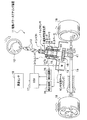
図3は、本発明の実施形態に係るトルクセンサの製造方法を示す図であり、内設部材配置工程を示す説明図である。
まず、図3を参照しながら内設部材配置工程に使用される金型8を説明する。ここで、内設部材とは、アッパケース部21(図2参照)を樹脂でモールド成形したときに、このアッパケース部21に内設される部材をいう。
<Description of internal member placement process>
FIG. 3 is a diagram illustrating a method for manufacturing a torque sensor according to an embodiment of the present invention, and is an explanatory diagram illustrating an internal member arranging step.
First, the metal mold | die 8 used for an internal member arrangement | positioning process is demonstrated, referring FIG. Here, the internal member refers to a member provided in the
図3に示すように、トルクセンサ1を形成する金型8を構成する基準金型81は、アッパケース部21(図2参照)の下面部分を形成する下型であり、例えば、台座82と上部芯だし軸棒部83とから構成されている。
As shown in FIG. 3, the
台座82は、ベアリング33、スペーサ6および第2コイルユニット7Bが嵌入されて支持される円柱形状の下部芯だし軸棒部82aと、この下部芯だし軸棒部82aの上端面中央に形成されて上部芯だし軸棒部83の下端部中央に形成された突起83aが挿入される盲穴82bとを有する。なお、台座82と下部芯だし軸棒部82aとは、精度よく形成されている。第1コイルユニット7Aおよび第2コイルユニット7Bは、基準金型81に、下部芯だし軸棒部82aを基準に精度よく保持されるように形成されている。
The
上部芯だし軸棒部83は、環状保持部材35内に装着されたベアリング34、および第1コイルユニット7A等が嵌入されて支持される軸棒からなり、下端部中央に、前記台座82に連結するための突起83aが一体形成されている。上部芯だし軸棒部83は、内径が、第1コイルユニット7Aおよび第2コイルユニット7Bの内径より小さく形成されていることにより、モールド成形後に、この上部芯だし軸棒部83を抜くことを可能にするため、前記台座82とは別体に形成されている。
なお、下部芯だし軸棒部82aおよび上部芯だし軸棒部83は、特許請求の範囲に記載の「芯だし軸棒部」に相当する。
The upper centering
The lower centering
第1工程である内設部材配置工程では、後記するセンサ収容ケース(ハウジング)2に内設されるベアリング33、スペーサ6、第2コイルユニット7B、環状保持部材35内に装着されたベアリング34、および第1コイルユニット7Aを、下部芯だし軸棒部82aおよび上部芯だし軸棒部83(芯だし軸棒部)に順番に嵌入して、基準金型81の台座82上に配置する。
In the internal member arrangement step which is the first step, a
<金型セット工程の説明>
図4は、本発明の実施形態に係るトルクセンサの製造方法を示す図であり、金型セット工程を示す説明図である。
図4を参照しながら金型セット工程に使用される金型8を説明する。
図4に示すように、基準金型81の上方に配置される金型8は、アッパケース部21(図2参照)の側面を形成する側部金型84と、アッパケース部21(図2参照)の側面を形成すると共に、アッパケース部21にインタフェースを設けるための穴部85aを形成するための側部金型85と、アッパケース部21の上面を形成する上部金型86と、から構成されている。
<Description of mold setting process>
FIG. 4 is a diagram illustrating a method for manufacturing a torque sensor according to an embodiment of the present invention, and is an explanatory diagram illustrating a mold setting process.
The mold 8 used in the mold setting process will be described with reference to FIG.
As shown in FIG. 4, the mold 8 disposed above the
第2工程である金型セット工程では、基準金型81上に、前記側部金型84,85、上部金型86をセットする。セット後、基準金型81、側部金型84,85および上部金型86の型締めを行う。
なお、側部金型84,85、上部金型86は、特許請求の範囲に記載の「その他の金型」に相当する。
In the mold setting process as the second process, the
The
<モールド成形工程の説明>
図5は、本発明の実施形態に係るトルクセンサの製造方法を示す図であり、モールド成形工程を示す説明図である。
次に、図5に示すように、射出ノズルから溶融樹脂Pをポート(図示せず)に噴射して、金型8内に溶融樹脂Pを充填し、第1コイルユニット7Aと第2コイルユニット7Bとスペーサ6等を樹脂モールド成形する。
<Description of molding process>
FIG. 5 is a diagram illustrating a method for manufacturing a torque sensor according to an embodiment of the present invention, and is an explanatory diagram illustrating a molding process.
Next, as shown in FIG. 5, the molten resin P is injected from the injection nozzle into a port (not shown), and the mold 8 is filled with the molten resin P, and the
図6は、本発明の実施形態に係るトルクセンサの製造方法を示す図であり、モールド成形されたアッパケース部を示す説明図である。
その後、金型8を冷却した後、上部金型86、側部金型84,85、上部芯だし軸棒部83、および基準金型81を外して製品Sを取り出す。すると、図6に示すような製品S(アッパケース部21)ができる。
FIG. 6 is a diagram illustrating a method for manufacturing a torque sensor according to an embodiment of the present invention, and is an explanatory diagram illustrating a molded upper case portion.
Thereafter, after the mold 8 is cooled, the
このトルクセンサ1の製造方法によれば、製品S(図6参照)は、図5に示すように、第1コイルユニット7Aおよび第2コイルユニット7Bが、シャフト4(図2参照)に見立てた基準金型81の下部芯だし軸棒部82aと、上部芯だし軸棒部83とによって、精度よく支持されて形成される。さらに、製品S(図6参照)は、アッパケース部21に見立てた基準金型81の台座82に対しても精度よく形成される。
According to the method for manufacturing the
このようにしてモールド成形された製品S(トルクセンサ1)は、図6に示すように、第1コイルユニット7Aと環状保持部材35と、第2コイルユニット7Bと、スペーサ6と、ベアリング33と、アッパケース部21とが一体となって1つの部品となる。このため、部品点数や組み付け工数を削減できると共に、アッパケース部21に内設される各部材の温度変化等による寸法精度管理を解消することがきる。
As shown in FIG. 6, the product S (torque sensor 1) molded in this way includes the first coil unit 7 </ b> A, the annular holding
そして、図2に示すように、トルクセンサ1は、磁歪膜51,52を有するシャフト4等を組み付けたロアケース部22に、前記アッパケース部21を合致させてボルト締めすることにより、完成される。
Then, as shown in FIG. 2, the
このようにして形成されたトルクセンサ1は、アッパケース部がコイルユニットと別体に形成される一般のトルクセンサと比較して、寸法精度を向上させるための加工精度管理や、温度変化によるがたつきの発生を解消させるためのばね部材が不要となるので、部品点数を削減して構造を簡素化し、大量生産性を向上させることができる。
The
≪トルクセンサの作用≫
次に、図1および図2を参照して、トルクセンサ1の作用を説明する。
図1に示すように、電動パワーステアリング装置11では、運転者がハンドル操作したときの操舵トルクを、トルクセンサ1を用いて検出すると共に、ECU17によりトルクセンサ1からの検出信号、車速センサ16からの検出信号等に応じてモータ14を駆動制御し、このときのモータ14のトルクを、減速装置15により増大させると共にピニオンギヤ41、ラック軸19を介在してタイヤ18,18に伝えている。
<< Operation of torque sensor >>
Next, the operation of the
As shown in FIG. 1, in the electric power steering device 11, the steering torque when the driver operates the steering wheel is detected using the
図2に示すように、トルクセンサ1は、アッパケース部21内において、スペーサ6の傾斜面6aと第2コイルユニット7Bのテーパ面74aとが互いに当接し合って内設されている。そして、モールド成形されたトルクセンサ1は、アッパケース部21を形成する樹脂が、成形後に収縮するので、アッパケース部21に内設された第1コイルユニット7Aと環状保持部材35と、第2コイルユニット7Bと、スペーサ6と、ベアリング33と、アッパケース部21とが軸方向および径方向に与圧を持って保持されている。このため、アッパケース部21に内設された各部材は、温度変化によりがたつくことが解消される。
その結果、トルクセンサ1は、各部材間の間隔が一定となり、がたつくことがないため、操舵トルクの検出精度が良好に保たれる。
As shown in FIG. 2, the
As a result, in the
また、トルクセンサ1を、自動車のステアリング機構に対して補助操舵力を付与する電動パワーステアリング装置11に適用する構成としたので、トルクセンサ1により操舵トルクの検出精度を高めることができ、電動パワーステアリング装置11の性能、信頼性等を高めることができる。
In addition, since the
[変形例]
なお、本発明は、前記実施形態に限定されるものではなく、その技術的思想の範囲内で種々の改造および変更が可能であり、本発明はこれら改造および変更された発明にも及ぶことは勿論である。
次に、図7および図8を主に参照して、本発明の変形例を説明する。なお、変形例において、図1〜図6に示した前記実施形態に係るトルクセンサ1と同一機能を有する部材の説明は省略する。
[Modification]
The present invention is not limited to the above-described embodiment, and various modifications and changes can be made within the scope of the technical idea. The present invention extends to these modifications and changes. Of course.
Next, a modification of the present invention will be described mainly with reference to FIGS. In addition, in a modification, description of the member which has the same function as the
≪第1変形例≫
まず、図7を参照して、本発明の第1変形例を説明する。
図7は、本発明の実施形態に係るトルクセンサの製造方法の第1変形例を示す図であり、モールド成形工程のときの状態を示す説明図である。
≪First modification≫
First, a first modification of the present invention will be described with reference to FIG.
Figure 7 is a diagram showing a first modification of the manufacturing method of engaging belt Rukusensa to an embodiment of the present invention, is an explanatory diagram showing a state when the molding process.
前記実施形態のトルクセンサ1(図2参照)は、図7に示す第1変形例のトルクセンサ1Aのように、第1コイルユニット7Cと第2コイルユニット7Dとの間に、比較的小型のベアリング37からなるスペーサ6Aを介在させてもよい。
また、図7に示すように、トルクセンサ1Aは、前記実施形態のスペーサ6およびベアリング33(図2参照)を備えていなくてもよい。このようにすれば、トルクセンサ1Aの小型化およびシンプル化を図ることができる。
The torque sensor 1 (see FIG. 2) of the above embodiment is relatively small between the
As shown in FIG. 7, the
さらに、図3に示す前記実施形態のトルクセンサ1の製造方法における金型8の下部芯だし軸棒部82aおよび上部芯だし軸棒部83は、図7に示す変形例の金型8Aの基準金型81Aのように、基準金型81Aに一体形成された1本の芯だし軸棒部83Aからなるものであってもよい。
このようにすれば、芯だし軸棒部83Aに連結部分がないため、さらに、芯だし軸棒部83Aの寸法精度を向上させることが可能である。
Further, the lower centering
In this way, since the centering shaft bar portion 83A has no connecting portion, it is possible to further improve the dimensional accuracy of the centering shaft rod portion 83A.
≪第2変形例≫
図8は、本発明の実施形態に係るトルクセンサの製造方法の第2変形例を示す図であり、トルクセンサの設置状態を示す電動パワーステアリング装置の要部概略断面図である。
図2に示す第1コイルユニット7Aおよび第2コイルユニット7Bのヨーク73,74は、図8に示すように、コイル71,72をそれぞれ備えたものであれば、なくても構わない。
≪Second modification≫
Figure 8 is a diagram showing a second modification of the manufacturing method of engaging belt Rukusensa to an embodiment of the present invention, it is a main part schematic cross-sectional view of an electric power steering apparatus showing an installation state of the torque sensor.
The
このようにすれば、ヨーク73,74の分だけ部品点数を削減して、製造時の内設部材配置工程(第1工程)の一部を省略化して、トルクセンサの構造を簡素化することができる。このようにした場合には、ヨークが省略された分だけ、誘磁率が低下するがトルクセンサとして使用することが可能である。
この場合、コイル71とコイル72との間にはスペーサ36を介在させ、そのコイル72とベアリング33との間にはスペーサ6を介在させる。
In this way, the number of parts is reduced by the amount of the
In this case, the
≪その他の変形例≫
例えば、図2に示す第1コイルユニット7Aおよび第2コイルユニット7Bの断面がそれぞれ略E字状に形成されて、コイル71,72それぞれ2つずつ備えてなる二層構造にしたものであってもよい。
≪Other variations≫
For example, the
図2に示すスペーサ6は、センサ収納部21bに収納されたコイルユニット7を付勢して、がたつきや、第1コイルユニット7Aと第2コイルユニット7Bとの間の隙間等を解消するための板ばねや、さらばねや、ばね座金、コイルばね等の弾性部材を介在したものであってもよい。
The
また、トルクセンサ1は、操舵トルクに応じてモータ14を駆動して車両の転舵を行う電動パワーステアリング装置11に適用した場合を例に挙げて説明したが、その他に、トーションバーや、その他の各種装置に適用してもよい。
The
1,1A トルクセンサ
2 センサ収容ケース(ハウジング)
4 シャフト
5 磁気特性変化部
6,6A,36 スペーサ
7 コイルユニット
7A,7C 第1コイルユニット
7B,7D 第2コイルユニット
8,8A 金型
11 電動パワーステアリング装置
14 モータ
21 アッパケース部(ハウジング)
34 ベアリング(スペーサ)
35 環状保持部材(スペーサ)
71,71A、72,72A コイル(検出コイル)
73,73A,74,74A ヨーク
81,81A 基準金型
82a 下部芯だし軸棒部(芯だし軸棒部)
83 上部芯だし軸棒部(芯だし軸棒部)
83A 芯だし軸棒部
84,85 側部金型(その他の金型)
86 上部金型(その他の金型)
1,
4
34 Bearing (spacer)
35 Annular holding member (spacer)
71, 71A, 72, 72A coil (detection coil)
73, 73A, 74,
83 Upper centering shaft bar (centering shaft bar)
83A Centering
86 Upper mold (other molds)
Claims (2)
前記第1コイルユニットと前記第2コイルユニットとの間に、前記第1コイルユニットおよび前記第2コイルユニットの内径よりも小さな内径の軸受を備えたトルクセンサの製造方法において、
下端側が他よりも小径である小径部を備えた上部芯だし軸棒部と、当該上部芯だし軸棒部が連結される下部芯だし軸棒部と、からなる芯だし軸棒部の前記下部芯だし軸棒部に前記第2コイルユニットを嵌入するステップと、
前記上部芯だし軸棒部の前記小径部に前記軸受を嵌入し、さらに、前記上部芯だし軸棒部を前記下部芯だし軸棒部に連結し、且つ、前記上部芯だし軸棒部に前記第1コイルユニットを嵌入するステップと、を有し、
前記第1コイルユニットと前記第2コイルユニットと前記軸受と芯だし軸棒部を基準金型上に配置する内設部材配置工程と、
前記基準金型にその他の金型をセットする金型セット工程と、
前記第1コイルユニットと前記第2コイルユニットと前記軸受とを樹脂によりモールド成形するモールド成形工程と、
前記モールド成形工程によるモールド成形後に、前記上部芯だし軸棒部と前記下部芯だし軸棒部の連結を解除して、前記基準金型、前記その他の金型、および、前記芯だし軸棒部をはずす工程と、
を有することを特徴とするトルクセンサの製造方法。 A plurality of substantially cylindrical first coil units and second coil units each having a plurality of detection coils provided so as to be opposed to magnetic property changing portions provided on a rotatable shaft;
In the method of manufacturing a torque sensor including a bearing having an inner diameter smaller than the inner diameters of the first coil unit and the second coil unit between the first coil unit and the second coil unit.
The lower part of the centering shaft bar part, which comprises an upper centering shaft bar part having a small diameter part whose lower end side is smaller than the others, and a lower centering shaft bar part to which the upper centering shaft bar part is connected. Inserting the second coil unit into the centering shaft portion;
The bearing is inserted into the small-diameter portion of the upper core shaft shaft portion, and the upper core shaft shaft rod portion is connected to the lower core shaft shaft rod portion, and the upper core shaft shaft rod portion is connected to the upper core shaft shaft rod portion. Inserting the first coil unit;
An internal member disposing step of disposing the first coil unit, the second coil unit, the bearing, and the centering shaft portion on a reference mold;
A mold setting step of setting other molds on the reference mold;
A molding step of molding the first coil unit, the second coil unit, and the bearing with resin;
After the molding by the molding process, the connection between the upper centering shaft bar part and the lower centering shaft bar part is released, and the reference mold, the other molds, and the centering shaft bar part. The process of removing
A method for manufacturing a torque sensor, comprising:
Priority Applications (4)
| Application Number | Priority Date | Filing Date | Title |
|---|---|---|---|
| JP2007022704A JP5180483B2 (en) | 2006-03-28 | 2007-02-01 | Torque sensor manufacturing method |
| EP07005703A EP1840545B8 (en) | 2006-03-28 | 2007-03-20 | Torque sensor and method of manufacturing the same |
| US11/723,752 US7624653B2 (en) | 2006-03-28 | 2007-03-21 | Torque sensor with a resin housing and a method of manufacturing the same |
| US12/511,198 US8225483B2 (en) | 2006-03-28 | 2009-07-29 | Method of manufacturing a torque sensor |
Applications Claiming Priority (3)
| Application Number | Priority Date | Filing Date | Title |
|---|---|---|---|
| JP2006087468 | 2006-03-28 | ||
| JP2006087468 | 2006-03-28 | ||
| JP2007022704A JP5180483B2 (en) | 2006-03-28 | 2007-02-01 | Torque sensor manufacturing method |
Publications (2)
| Publication Number | Publication Date |
|---|---|
| JP2007292727A JP2007292727A (en) | 2007-11-08 |
| JP5180483B2 true JP5180483B2 (en) | 2013-04-10 |
Family
ID=38247800
Family Applications (1)
| Application Number | Title | Priority Date | Filing Date |
|---|---|---|---|
| JP2007022704A Expired - Fee Related JP5180483B2 (en) | 2006-03-28 | 2007-02-01 | Torque sensor manufacturing method |
Country Status (3)
| Country | Link |
|---|---|
| US (2) | US7624653B2 (en) |
| EP (1) | EP1840545B8 (en) |
| JP (1) | JP5180483B2 (en) |
Families Citing this family (23)
| Publication number | Priority date | Publication date | Assignee | Title |
|---|---|---|---|---|
| EP1892172B1 (en) * | 2006-08-21 | 2009-09-16 | JTEKT Corporation | Steering apparatus |
| DE102007062156A1 (en) * | 2007-12-21 | 2009-06-25 | Schaeffler Kg | Bottom bracket with torque sensors |
| JP2009204533A (en) * | 2008-02-28 | 2009-09-10 | Honda Motor Co Ltd | Magnetostrictive torque sensor, its manufacturing method, and electric power steering device |
| US8584533B2 (en) | 2008-03-03 | 2013-11-19 | Honda Motor Co., Ltd. | Magnetostrictive torque sensor device, manufacturing method thereof, and vehicle steering apparatus |
| FR2929004B1 (en) * | 2008-03-18 | 2010-08-20 | Jtekt Europe Sas | TORQUE DETECTION DEVICE FOR DIRECTION OF A MOTOR VEHICLE |
| DE102008056302A1 (en) * | 2008-11-07 | 2010-05-12 | Thyssenkrupp Egm Gmbh | Device for transmitting torques |
| US7757570B1 (en) * | 2009-02-06 | 2010-07-20 | Gm Global Technology Operations, Inc. | Torque sensor with alignment system |
| US8701503B2 (en) * | 2009-04-17 | 2014-04-22 | Honda Motor Co., Ltd. | Magnetostrictive torque sensor and electrical power steering device |
| JP4866437B2 (en) * | 2009-04-17 | 2012-02-01 | 本田技研工業株式会社 | Magnetostrictive torque sensor and manufacturing method thereof |
| JP5508826B2 (en) * | 2009-12-10 | 2014-06-04 | 株式会社ショーワ | Torque sensor |
| KR101427440B1 (en) * | 2010-02-10 | 2014-08-08 | 주식회사 만도 | Rack Bar Supporting Device of Steering Apparatus for Vehicle |
| JP5566750B2 (en) * | 2010-03-31 | 2014-08-06 | 本田技研工業株式会社 | Electric power steering device for saddle-ride type vehicles |
| JP5405443B2 (en) * | 2010-12-06 | 2014-02-05 | 本田技研工業株式会社 | Electric power steering device |
| DE102011054983B4 (en) * | 2011-11-02 | 2024-02-01 | Robert Bosch Gmbh | SENSOR ASSEMBLY FOR ELECTRICAL POWER STEERING |
| JP2013124904A (en) | 2011-12-14 | 2013-06-24 | Honda Motor Co Ltd | Magnetostrictive torque sensor and method for manufacturing the same |
| JP6227880B2 (en) * | 2013-03-29 | 2017-11-08 | 株式会社ショーワ | Bobbin, torque detection device and steering device |
| JP2015194430A (en) * | 2014-03-31 | 2015-11-05 | 本田技研工業株式会社 | Vehicle power steering system and manufacturing method of the same |
| US10450863B2 (en) | 2016-06-02 | 2019-10-22 | General Electric Company | Turbine engine shaft torque sensing |
| JP6910991B2 (en) | 2018-07-02 | 2021-07-28 | 日本電産コパル電子株式会社 | Torque sensor support device |
| US11967250B2 (en) * | 2018-09-05 | 2024-04-23 | Tellyes Scientific Inc. | Eyepiece, eye simulator device, mannequin simulator and training method |
| DE102019214406A1 (en) * | 2019-09-20 | 2021-03-25 | Robert Bosch Gmbh | Steering device and method for manufacturing a steering device |
| JP7596682B2 (en) | 2020-09-16 | 2024-12-10 | 日本精工株式会社 | Magnetostrictive torque sensor |
| CN113405716B (en) * | 2021-07-21 | 2022-10-18 | 广东新环机电装备制造有限公司 | Over-torsion detection device adopting tension and pressure sensor |
Family Cites Families (22)
| Publication number | Priority date | Publication date | Assignee | Title |
|---|---|---|---|---|
| JPH01126540A (en) | 1987-11-11 | 1989-05-18 | Hitachi Ltd | Ion selecting electrode |
| JPH01126540U (en) * | 1988-02-22 | 1989-08-29 | ||
| JP2964667B2 (en) * | 1991-03-04 | 1999-10-18 | 株式会社スリーボンド | Different material composite injection molding machine |
| JP2652313B2 (en) * | 1991-12-26 | 1997-09-10 | 株式会社ユニシアジェックス | Torque measuring device |
| JPH0678833A (en) | 1992-09-07 | 1994-03-22 | Daifuku Co Ltd | Rack structure |
| JP2572319Y2 (en) * | 1993-04-12 | 1998-05-20 | 株式会社ユニシアジェックス | Magnetostrictive torque sensor |
| JPH0783769A (en) * | 1993-09-17 | 1995-03-31 | Matsushita Electric Ind Co Ltd | Torque sensor and production thereof |
| JP3024905B2 (en) * | 1994-06-13 | 2000-03-27 | 本田技研工業株式会社 | Sensor |
| US5526704A (en) * | 1994-11-01 | 1996-06-18 | Unisia Jecs Corporation | Structure of magnetostrictive torque sensor applicable to sensor for detecting torque applied to rotatable shaft |
| JP3216982B2 (en) * | 1996-01-24 | 2001-10-09 | 株式会社ユニシアジェックス | Magnetostrictive torque detector |
| JP3223242B2 (en) * | 1997-03-25 | 2001-10-29 | 株式会社ホンダロック | Torque detector |
| JPH11344394A (en) * | 1998-05-29 | 1999-12-14 | Toyota Autom Loom Works Ltd | Torque sensor |
| JP3656810B2 (en) * | 1999-04-27 | 2005-06-08 | 株式会社ショーワ | Circuit case |
| JP3614080B2 (en) * | 1999-05-31 | 2005-01-26 | 株式会社村田製作所 | Manufacturing method of chip inductor |
| DE10010838B4 (en) * | 2000-03-09 | 2011-07-07 | ThyssenKrupp Presta SteerTec GmbH, 40476 | Method for producing a transmission and steering gear for a motor vehicle |
| EP1241074B1 (en) * | 2001-03-16 | 2006-07-19 | Mando Corporation | Torque sensor for vehicle |
| JP2003004555A (en) * | 2001-06-18 | 2003-01-08 | Aisin Seiki Co Ltd | Magnetostrictive torque sensor and method of manufacturing the same |
| JP2003100783A (en) | 2001-09-20 | 2003-04-04 | Mitsubishi Electric Corp | Apparatus and method for resin sealing |
| US6758105B2 (en) * | 2002-11-22 | 2004-07-06 | Visteon Global Technologies, Inc. | Magnetoelastic torque sensor assembly |
| JP4144364B2 (en) * | 2003-01-31 | 2008-09-03 | 株式会社ジェイテクト | Torque detection device |
| JP4516276B2 (en) | 2003-02-04 | 2010-08-04 | 本田技研工業株式会社 | Magnetostrictive torque sensor |
| JP2005156468A (en) * | 2003-11-27 | 2005-06-16 | Showa Corp | Torque sensor |
-
2007
- 2007-02-01 JP JP2007022704A patent/JP5180483B2/en not_active Expired - Fee Related
- 2007-03-20 EP EP07005703A patent/EP1840545B8/en not_active Not-in-force
- 2007-03-21 US US11/723,752 patent/US7624653B2/en active Active
-
2009
- 2009-07-29 US US12/511,198 patent/US8225483B2/en not_active Expired - Fee Related
Also Published As
| Publication number | Publication date |
|---|---|
| EP1840545B1 (en) | 2011-12-28 |
| US7624653B2 (en) | 2009-12-01 |
| US20070283767A1 (en) | 2007-12-13 |
| US20090288288A1 (en) | 2009-11-26 |
| JP2007292727A (en) | 2007-11-08 |
| EP1840545A2 (en) | 2007-10-03 |
| EP1840545B8 (en) | 2012-04-11 |
| US8225483B2 (en) | 2012-07-24 |
| EP1840545A3 (en) | 2009-01-07 |
Similar Documents
| Publication | Publication Date | Title |
|---|---|---|
| JP5180483B2 (en) | Torque sensor manufacturing method | |
| US8482177B2 (en) | Torque rotor and method for manufacturing the same | |
| US7752923B2 (en) | Magnetostrictive torque sensor | |
| EP2243685B1 (en) | Electric power steering system | |
| EP2832626B1 (en) | Electric power steering device | |
| JP6883255B2 (en) | Torque detector | |
| WO2011070826A1 (en) | Method of manufacturing motorized power steering device | |
| US8302492B2 (en) | Magnetostrictive torque sensor and electric power steering apparatus | |
| JP5153490B2 (en) | Torque sensor | |
| JP2011257225A (en) | Torque sensor | |
| US9573621B2 (en) | Power steering apparatus for vehicle and method of producing the same | |
| JP2004239652A (en) | Magnetostrictive torque sensor | |
| JP5557006B2 (en) | Manufacturing method of electric power steering apparatus | |
| JP5508826B2 (en) | Torque sensor | |
| EP3376070B1 (en) | Method for manufacturing worm reducer, worm reducer and electric power steering system | |
| JP5054320B2 (en) | Magnetostrictive torque sensor | |
| US20010052436A1 (en) | Electric power steering apparatus | |
| CN115885158A (en) | Torque sensor and method for manufacturing magnet assembly | |
| JP2006046987A (en) | Torque sensor and its manufacturing method | |
| JP4829921B2 (en) | Anisotropy imparting method for magnetostrictive torque sensor | |
| JP2005156468A (en) | Torque sensor | |
| JP7367654B2 (en) | torque sensor | |
| JP2005172433A (en) | Torque sensor | |
| JP2005172434A (en) | Torque sensor | |
| JP2008256431A (en) | Torque sensor |
Legal Events
| Date | Code | Title | Description |
|---|---|---|---|
| A621 | Written request for application examination |
Free format text: JAPANESE INTERMEDIATE CODE: A621 Effective date: 20091127 |
|
| A131 | Notification of reasons for refusal |
Free format text: JAPANESE INTERMEDIATE CODE: A131 Effective date: 20111206 |
|
| A977 | Report on retrieval |
Free format text: JAPANESE INTERMEDIATE CODE: A971007 Effective date: 20111207 |
|
| A521 | Request for written amendment filed |
Free format text: JAPANESE INTERMEDIATE CODE: A523 Effective date: 20120206 |
|
| A131 | Notification of reasons for refusal |
Free format text: JAPANESE INTERMEDIATE CODE: A131 Effective date: 20121016 |
|
| A521 | Request for written amendment filed |
Free format text: JAPANESE INTERMEDIATE CODE: A523 Effective date: 20121207 |
|
| TRDD | Decision of grant or rejection written | ||
| A01 | Written decision to grant a patent or to grant a registration (utility model) |
Free format text: JAPANESE INTERMEDIATE CODE: A01 Effective date: 20130108 |
|
| A61 | First payment of annual fees (during grant procedure) |
Free format text: JAPANESE INTERMEDIATE CODE: A61 Effective date: 20130111 |
|
| R150 | Certificate of patent or registration of utility model |
Ref document number: 5180483 Country of ref document: JP Free format text: JAPANESE INTERMEDIATE CODE: R150 |
|
| LAPS | Cancellation because of no payment of annual fees |