JP5172115B2 - Swirl compressor and method of manufacturing vortex compressor - Google Patents
Swirl compressor and method of manufacturing vortex compressor Download PDFInfo
- Publication number
- JP5172115B2 JP5172115B2 JP2006204523A JP2006204523A JP5172115B2 JP 5172115 B2 JP5172115 B2 JP 5172115B2 JP 2006204523 A JP2006204523 A JP 2006204523A JP 2006204523 A JP2006204523 A JP 2006204523A JP 5172115 B2 JP5172115 B2 JP 5172115B2
- Authority
- JP
- Japan
- Prior art keywords
- casing
- motor
- impeller
- rotor
- assembled
- Prior art date
- Legal status (The legal status is an assumption and is not a legal conclusion. Google has not performed a legal analysis and makes no representation as to the accuracy of the status listed.)
- Active
Links
- 238000004519 manufacturing process Methods 0.000 title claims description 9
- 239000012530 fluid Substances 0.000 claims description 15
- 230000002093 peripheral effect Effects 0.000 claims description 8
- 239000000758 substrate Substances 0.000 description 5
- 238000005192 partition Methods 0.000 description 3
- WABPQHHGFIMREM-UHFFFAOYSA-N lead(0) Chemical compound [Pb] WABPQHHGFIMREM-UHFFFAOYSA-N 0.000 description 2
- 238000010586 diagram Methods 0.000 description 1
- 238000005304 joining Methods 0.000 description 1
- 239000007788 liquid Substances 0.000 description 1
- 238000003754 machining Methods 0.000 description 1
- 238000000034 method Methods 0.000 description 1
Images


Landscapes
- Structures Of Non-Positive Displacement Pumps (AREA)
Description
本発明は、流体(空気、ガスなどの気体、液体など)を圧送りする渦流式圧縮機及び渦流式圧縮機の製造方法に関する。 The present invention relates to a vortex compressor that pumps fluid (air, gas such as gas, liquid, etc.) and a method of manufacturing the vortex compressor.
例えば渦流式圧縮機の場合、回転羽根が回転すると吸込み口付近でケーシング凹溝が拡大する部位から流体を吸い込んで、回転羽根の回転が進むにつれて外周方向へ平面視で渦を巻くように流体が移動しながら加速加圧され、吐出口付近でケーシング凹溝が遮断される部位から回転軸と直交する向き(径方向外側)に吐出されるようになっている。 For example, in the case of a vortex compressor, when the rotating blade rotates, the fluid is sucked in from the portion where the casing concave groove expands in the vicinity of the suction port, and as the rotating blade advances, the fluid wraps around the outer periphery in a plan view. It is accelerated and pressurized while moving, and is discharged in a direction (radially outward) perpendicular to the rotation axis from a portion where the casing groove is blocked near the discharge port.
渦流式圧縮機の一例として、図4のブロワーの構成について説明する。ブロワー51はモータ52と回転羽根(インペラー)53を具備している。モータ52には、例えばインナーロータ型のブラシレスモータが用いられる。モータケース54aとモータケース54bに固定子コア55やモータ基板56が挟み込まれて一体に組み付けられている。回転軸57はモータケース54a、54bに軸受(ベアリング)58a、58bを介して回転可能に支持されている。回転軸57には、ロータマグネット59が固定子コア55に対向して設けられている。
As an example of the vortex compressor, the configuration of the blower in FIG. 4 will be described. The
モータ52の回転軸57はモータケース54bよりインペラー53側へ延設されている。この回転軸57にカラー60を嵌め込んで軸方向の位置を調節してインペラー53が組み付けられる。インペラー53は、ケーシング61a、61b内に収納されている。ケーシング61aはモータケース54bにねじ止め固定されている。
The
図5において、インペラー53は円板状をしており、円板外周側の両面に放射状に形成されたインペラー側凹部62と仕切り壁63とが周方向に交互に形成されている。また、ケーシング61の内壁面にもインペラー側凹部62に対向してケース側凹部64が周方向に矢印Pで示す範囲で設けられている。インペラー53が矢印Q方向に回転すると、インペラー側凹部62とケース側凹部64が対向する矢印位置Rで圧力が低下するため吸込み口65より流体を吸引し、インペラー側凹部62が対向するケース側凹部64が遮断される矢印位置Sで吐出口66より高圧の流体が吐出されるようになっている(特許文献1参照)。
上述した渦流式圧縮機においては、モータ52の組立誤差、即ちモータケース54a、54bと固定子コア55の組立誤差の累積により回転軸57のモータケース54bの取付面に対する直角度が出し難くなる。一方、モータケース54bの取付面とケーシング61a、61bの平行度は各々の取付面を加工すれば所定の精度を出すことは可能である。しかしながら、モータケース54bの取付面に対する回転軸57の直角度がモータ52の組立誤差から精度が出し難いため、インペラー53とケーシング61a、61bとの平行度が低下するという課題がある。よって、少なくともインペラー53とケーシング61a、61bの干渉を回避するためには、ケーシング61a、61bとのクリアランスを大きくとる(例えば0.2mm程度設ける)必要がある。また、インペラー53とケーシング61a、61bとの隙間が大きくなれば、流体の漏れや逆流が発生しやすく圧力損失が大きくなり効率が低下する。
In the above-described vortex compressor, the assembly error of the
本発明はこれらの課題を解決すべくなされたものであり、その目的とするところは、インペラーと回転軸との組付精度を向上し、インペラーとケーシングのクリアランスの縮小均一化を図り効率のよい渦流式圧縮機及びその製造方法を提供することにある。 The present invention has been made to solve these problems, and the object of the present invention is to improve the assembly accuracy between the impeller and the rotating shaft, and to reduce and equalize the clearance between the impeller and the casing with high efficiency. An object of the present invention is to provide a vortex compressor and a manufacturing method thereof.
本発明は上記目的を達成するため、次の構成を備える。
外周側に放射状に設けられた羽根溝が全周にわたって形成されたインペラーが、当該羽根溝に対向する部位に凹溝が形成されたケーシングに収容されてモータ回転子軸に一体に組み付けられ、前記インペラーが回転して前記羽根溝と前記ケーシング凹溝が対向する吸込み口から流体を吸い込み、前記羽根溝と前記ケーシング凹溝が前記ケーシングにより遮断される吐出口より吐出される渦流式圧縮機であって、前記ケーシング内に設けられた前記モータ回転子軸を支持する軸受部間に前記インペラーが組み付けられ、該ケーシングより外方へ延設された前記モータ回転子軸に回転子が一体に組み付けられ、モータ側に臨むケーシング側面中央部に筒体部が軸方向に突設されるとともにその外周に凹部が形成され、該凹部にモータ基板が前記筒体部を基板孔に挿入して収納されており、前記筒体部と回転子が軸方向にオーバーラップさせて組み付けられ、固定子が組み付けられたモータハウジングが当該固定子と前記回転子が対向するように前記ケーシングを基準にして当該ケーシングがモータを収容するモータハウジングを兼用して一体に組み付けられていることを特徴とする。
一方、上述した渦流式圧縮機の製造方法においては、前記ケーシング内に設けられた軸受部間に回転子軸を中心にインペラーを回転可能に収容する工程と、前記ケーシングより外方へ延設された前記回転子軸に回転子を一体に組み付ける工程と、固定子が組み付けられたモータハウジングを当該固定子と前記回転子が対向するように前記ケーシングを基準にして、当該ケーシングに一体に組み付ける工程を含むことを特徴とする。
In order to achieve the above object, the present invention comprises the following arrangement.
An impeller in which blade grooves provided radially on the outer peripheral side are formed over the entire circumference are housed in a casing in which concave grooves are formed in a portion facing the blade grooves, and are assembled integrally with the motor rotor shaft, An eddy current compressor in which an impeller rotates to suck fluid from a suction port where the blade groove and the casing groove face each other, and the blade groove and the casing groove are discharged from a discharge port blocked by the casing. The impeller is assembled between bearings that support the motor rotor shaft provided in the casing, and the rotor is integrally assembled to the motor rotor shaft that extends outward from the casing. A cylindrical body portion is projected in the axial direction at the central portion of the casing side surface facing the motor side, and a recess is formed on the outer periphery thereof, and the motor substrate is placed in the recess The cylindrical body and the rotor are assembled so as to overlap each other in the axial direction, and the motor housing in which the stator is assembled is opposed to the stator and the rotor. As described above, the casing is integrally assembled so as to serve as a motor housing that accommodates a motor with reference to the casing.
On the other hand, in the above-described method for manufacturing a vortex compressor, a step of accommodating an impeller rotatably around a rotor shaft between bearing portions provided in the casing, and extending outward from the casing. a step of assembling together the rotor in the rotor shaft and the motor housing the stator is assembled on the basis of the said casing such that the rotor and the stator is opposed, steps of assembling together to the casing It is characterized by including.
上述した、渦流式圧縮機及びその製造方法を用いれば、ケーシング内に設けられた軸受部間にインペラーが組み付けられ、該ケーシングより外方へ延設された回転子軸に回転子が一体に組み付けられ、固定子が組み付けられたモータハウジングが当該固定子と回転子が対向するようにケーシングを基準にして当該ケーシングに一体に組み付けられているので、ケーシングと回転軸との直角度が高く、インペラーとケーシングの平行度も高くなり、インペラーとケーシングのクリアランスが縮小かつ均一化し、効率のよい渦流式圧縮機を提供することができる。
また、モータ側に臨むケーシング側面に筒体部及び凹部が形成され、該凹部にモータ基板が収納され該筒体部と回転子が軸方向にオーバーラップさせて組み付けられていると、ケーシングの一部をモータハウジングと兼用することで、部品点数を減らして組立性が向上し、圧縮機を軸方向に大型化せずに、組立誤差、加工誤差の累積を抑え、軸受けスパンを大きく取ることができるので回転振れを抑えることができる。
特に、ケーシング内に設けられた軸受部間に回転子軸を中心にインペラーを回転可能に収容してから、回転軸に回転子が組み付けられ、モータハウジングがケーシングを基準にして当該ケーシングに一体に組み付けられるので、インペラーと回転軸との組み付け精度が高く、組立性もよい。
If the eddy current compressor and the manufacturing method thereof described above are used, the impeller is assembled between the bearing portions provided in the casing, and the rotor is integrally assembled to the rotor shaft extending outward from the casing. The motor housing with the stator assembled is integrally assembled with the casing with respect to the casing so that the stator and the rotor face each other, so the perpendicularity between the casing and the rotating shaft is high, and the impeller As a result, the parallelism of the casing is increased, the clearance between the impeller and the casing is reduced and uniformed, and an efficient vortex compressor can be provided.
In addition, a cylindrical body and a recess are formed on the side of the casing facing the motor side, the motor substrate is housed in the recess, and the cylindrical body and the rotor are assembled so as to overlap in the axial direction. By combining the motor housing with the motor housing, the number of parts can be reduced to improve the assembly performance, and the assembly error and machining error can be suppressed and the bearing span can be increased without increasing the size of the compressor in the axial direction. As a result, rotational runout can be suppressed.
In particular, an impeller is rotatably accommodated around a rotor shaft between bearings provided in the casing, and then the rotor is assembled to the rotation shaft, and the motor housing is integrated with the casing based on the casing. Since it is assembled, the assembly accuracy between the impeller and the rotary shaft is high, and the assembly is good.
以下、本発明に係る渦流式圧縮機及びその製造方法について最良の実施形態について、添付図面を参照しながら説明する。以下では、渦流式圧縮機の一例として、ブロワーについて説明するものとする。ブロワーは、モータの回転子軸に外周側に放射状の羽根に仕切られた羽根溝が周方向に形成されたインペラーが羽根溝に対向する部位にケーシング凹溝が形成されたケーシングに収容されている。インペラーが回転して羽根溝とケーシング凹溝が対向する外周側吸込み口から流体を吸い込み、羽根溝とケーシング凹溝がケーシングにより遮断される外周側吐出口より吐出されるようになっている。モータとしては、DCブラシ付モータ、DCブラシレスモータなどが用いられ、インナーロータ型、アウターロータ型のいずれのタイプでも適用できる。 BEST MODE FOR CARRYING OUT THE INVENTION The best embodiment of the eddy current compressor and the manufacturing method thereof according to the present invention will be described below with reference to the accompanying drawings. Hereinafter, a blower will be described as an example of the vortex compressor. The blower is housed in a casing in which a casing groove is formed in a portion where an impeller in which a blade groove partitioned by radial blades on the outer peripheral side is formed in a circumferential direction on the rotor shaft of the motor is opposed to the blade groove. . The impeller rotates to suck fluid from the outer peripheral suction port where the blade groove and the casing concave groove face each other, and the blade groove and the casing concave groove are discharged from the outer peripheral discharge port blocked by the casing. As the motor, a motor with a DC brush, a DC brushless motor, or the like is used, and any of an inner rotor type and an outer rotor type can be applied.
渦流式圧縮機の概略構成について図1及び図2を参照して説明する。
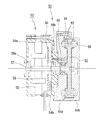
図1において、ケーシング1は、第1ケース2及び第2ケース3を掌合してねじ止めされている。このケーシング1内には第1ケース2に軸受部(ベアリング)4が、第2ケース3に軸受部(ベアリング)5が各々組み込まれている。このベアリング4、5に回転軸6が回転可能に支持されている。回転軸6には、インペラー7がベアリング4、5に軸方向位置が規定されて組み付けられている。
A schematic configuration of the vortex compressor will be described with reference to FIGS. 1 and 2.
In FIG. 1, a casing 1 is screwed together with a
図2において、インペラー7は円板状をしており、外周側の両面に放射状に形成された羽根溝(インペラー側凹部)8と仕切り壁9とが全周にわたって交互に形成されている。また、図1において、第1ケース2及び第2ケース3の内壁面にもインペラー側凹部8に対向してケース側凹部10が周方向に矢印Pで示す範囲で設けられている。インペラー7が矢印Q方向に回転すると、インペラー側凹部8とケース側凹部10が対向する矢印位置Rで圧力が低下するため吸込み口11より流体を吸引し、インペラー側凹部8が対向するケース側凹部10が遮断される矢印位置Sでケーシング1に設けられる吐出口12より高圧の流体が吐出されるようになっている。
インペラー7の中心線Mにおける断面を展開した模式図を図3に示す。インペラー7が矢印Q方向に回転すると、インペラー側凹部8とケース側凹部10が対向する位置でスペースが広がるため圧力低下が起こる。このため、吸込み口11からインペラー7内へ流体の吸引が行なわれる。また、インペラー7が回転するにしたがって高圧になった流体は、ケース側凹部10が遮断されるケーシング壁面21に突き当たって吐出口12へ導かれる。
In FIG. 2, the
FIG. 3 shows a schematic diagram of a developed cross section at the center line M of the
図1において、回転軸6は第2ケース3より外方へ延設されている。この回転軸6に回転子(ロータマグネット)16が一体に組み付けられている。第2ケース3のモータ側側面には中心部に筒体部13が突設されその周囲に凹部14が形成されている。筒体部13の内壁側にはベアリング5が保持されている。また、筒体部13の外周側には、モータ基板15が嵌め込まれて凹部14に収納されている。該凹部14にモータ基板15が収納され筒体部13と回転子16が軸方向にオーバーラップさせて組み付けられている。
In FIG. 1, the
また、モータハウジング17の内壁には、固定子18が組み付けられている。固定子18は固定子コアと該固定子コアにコイルが巻き付けられている。モータハウジング17は、固定子18と回転子16が対向するように位置合わせし、固定子18の外形を軸方向で第2ケース3とモータハウジング17で嵌め合わせたうえでねじ止め固定されている。第2ケース3とモータハウジング17でモータを形成するようになっている。モータ基板15に接続するリード線19は、第2ケース3とモータハウジング17の開口部20から引き出される。このようにケーシング1の一部をモータハウジング17と兼用することで部品点数を減らして組立性を向上させることができる。また、筒体部13に回転子16の一部をオーバーラップさせて収納するようにすると、ブロワーを軸方向に大型化せず、軸受けスパンを大きくすることができ回転振れを抑えることができる。
A
次に、渦流式圧縮機の製造方法について説明すると、ケーシング1を構成する第1のケース2と第2のケース3を掌合して形成される空間部にインペラー7が収容される。
第1、第2ケース2、3に設けられた軸受部4、5間に回転子軸6を挿入し、該第1、第2ケース2、3がねじ止めされて回転軸6を中心にインペラー7が回転可能にケーシング1内に収容される。
Next, the manufacturing method of the vortex compressor will be described. The
The
また、ケーシング1より外方へ延設された回転軸6に回転子16が一体に組み付けられる。第2ケース3に形成された凹部14には、モータ基板15が筒体部13の外周側に組み付けられる。固定子18が組み付けられたモータハウジング17が当該固定子17と回転子16が対向するように位置合わせし、固定子18の外形を軸方向で第2ケース3とモータハウジング17で嵌め合わせたうえでねじ止め固定されている。
In addition, a
このように、ケーシング1内に軸受部4、5間に支持された回転子軸6を中心にインペラー7を収容してから、回転軸6に回転子16が組み付けられ、モータハウジング17がケーシング1を基準にして一体に組み付けられるので、ケーシング1と回転子軸6との直角度が高く、インペラー7とケーシング1の平行度も高くなり、インペラー7とケーシング1のクリアランスが縮小かつ均一化することができる。一例をあげると、インペラー7とケーシング1(第1ケース2及び第2ケース3)とのクリアランスが通常0.1mm〜0.15mmのところを0.1mm以下に縮小することができる。よって、流体の漏れや逆流が生じない、圧力損失が少ない効率のよい渦流式圧縮機を提供することができる。
As described above, the
上記実施例は、ブロワーについて説明したが、これに限定されるものではなく、流体を圧送りする電動ポンプなど他の装置にも応用できる。 Although the said Example demonstrated the blower, it is not limited to this, It can apply also to other apparatuses, such as an electric pump which pumps a fluid.
1 ケーシング
2 第1ケース
3 第2ケース
4、5 ベアリング
6 回転軸
7 インペラー
8 インペラー側凹部
9 仕切り壁
10 ケース側凹部
11 吸込み口
12 吐出口
13 筒体部
14 凹部
15 モータ基板
16 回転子
17 モータハウジング
18 固定子
19 リード線
20 開口部
21 ケーシング壁面
1 casing
2
4, 5
7
9 Partition wall
10 Case side recess
11
13 Tube part
14 recess
15 Motor board
16 Rotor
17 Motor housing
18 Stator
19 Lead wire
20
Claims (2)
前記ケーシング内に設けられた前記モータ回転子軸を支持する軸受部間に前記インペラーが組み付けられ、該ケーシングより外方へ延設された前記モータ回転子軸に回転子が一体に組み付けられ、
モータ側に臨むケーシング側面中央部に筒体部が軸方向に突設されるとともにその外周に凹部が形成され、該凹部にモータ基板が前記筒体部を基板孔に挿入して収納されており、
前記筒体部と回転子が軸方向にオーバーラップさせて組み付けられ、固定子が組み付けられたモータハウジングが当該固定子と前記回転子が対向するように前記ケーシングを基準にして当該ケーシングがモータを収容するモータハウジングを兼用して一体に組み付けられていることを特徴とする渦流式圧縮機。 An impeller in which blade grooves provided radially on the outer peripheral side are formed over the entire circumference are housed in a casing in which concave grooves are formed in a portion facing the blade grooves, and are assembled integrally with the motor rotor shaft, An eddy current compressor in which an impeller rotates to suck fluid from a suction port where the blade groove and the casing groove face each other, and the blade groove and the casing groove are discharged from a discharge port blocked by the casing. And
The impeller is assembled between bearings that support the motor rotor shaft provided in the casing, and the rotor is integrally assembled to the motor rotor shaft that extends outward from the casing,
A cylindrical part protrudes in the axial direction in the central part of the casing side facing the motor side, and a recess is formed in the outer periphery thereof, and the motor board is stored in the recess by inserting the cylindrical part into the board hole. ,
The cylindrical body and the rotor are assembled so as to overlap each other in the axial direction, and the motor housing on which the stator is assembled is used with the casing as a reference so that the stator and the rotor face each other. A vortex-type compressor characterized in that it is integrally assembled to serve as a motor housing.
前記ケーシング内に設けられた軸受部間に回転子軸を中心にインペラーを回転可能に収容する工程と、
前記ケーシングより外方へ延設された前記回転子軸に回転子を一体に組み付ける工程と、
固定子が組み付けられたモータハウジングを当該固定子と前記回転子が対向するように前記ケーシングを基準にして、当該ケーシングに一体に組み付ける工程を含むことを特徴とする渦流式圧縮機の製造方法。 A method of manufacturing a vortex compressor according to claim 1,
A step of rotatably accommodating an impeller around a rotor shaft between bearing portions provided in the casing;
A step of assembling together the rotor in the rotor shaft which extends outwardly from said casing,
The motor housing the stator is assembled on the basis of the said casing such that the rotor and the stator is opposed, the manufacturing method of the vortex type compressor characterized in that it comprises a step of assembling together on the casing.
Priority Applications (1)
| Application Number | Priority Date | Filing Date | Title |
|---|---|---|---|
| JP2006204523A JP5172115B2 (en) | 2006-07-27 | 2006-07-27 | Swirl compressor and method of manufacturing vortex compressor |
Applications Claiming Priority (1)
| Application Number | Priority Date | Filing Date | Title |
|---|---|---|---|
| JP2006204523A JP5172115B2 (en) | 2006-07-27 | 2006-07-27 | Swirl compressor and method of manufacturing vortex compressor |
Publications (2)
| Publication Number | Publication Date |
|---|---|
| JP2008031889A JP2008031889A (en) | 2008-02-14 |
| JP5172115B2 true JP5172115B2 (en) | 2013-03-27 |
Family
ID=39121596
Family Applications (1)
| Application Number | Title | Priority Date | Filing Date |
|---|---|---|---|
| JP2006204523A Active JP5172115B2 (en) | 2006-07-27 | 2006-07-27 | Swirl compressor and method of manufacturing vortex compressor |
Country Status (1)
| Country | Link |
|---|---|
| JP (1) | JP5172115B2 (en) |
Families Citing this family (2)
| Publication number | Priority date | Publication date | Assignee | Title |
|---|---|---|---|---|
| JP5622777B2 (en) | 2012-03-23 | 2014-11-12 | シナノケンシ株式会社 | Compressor or vacuum machine |
| JP2017096173A (en) * | 2015-11-24 | 2017-06-01 | 愛三工業株式会社 | Vortex pump |
Family Cites Families (4)
| Publication number | Priority date | Publication date | Assignee | Title |
|---|---|---|---|---|
| JPH0312045Y2 (en) * | 1986-12-17 | 1991-03-22 | ||
| JP3203543B2 (en) * | 1995-12-11 | 2001-08-27 | 愛三工業株式会社 | Magnetic coupling pump |
| DE19913950A1 (en) * | 1999-03-26 | 2000-09-28 | Rietschle Werner Gmbh & Co Kg | Side channel blower |
| CA2301415A1 (en) * | 1999-04-19 | 2000-10-19 | Capstone Turbine Corporation | Helical flow compressor/turbine permanent magnet motor/generator |
-
2006
- 2006-07-27 JP JP2006204523A patent/JP5172115B2/en active Active
Also Published As
| Publication number | Publication date |
|---|---|
| JP2008031889A (en) | 2008-02-14 |
Similar Documents
| Publication | Publication Date | Title |
|---|---|---|
| KR100568183B1 (en) | Turbo compressor | |
| JP3809438B2 (en) | Centrifugal blower | |
| JP5172115B2 (en) | Swirl compressor and method of manufacturing vortex compressor | |
| JP2008295214A (en) | Electric motor and compressor | |
| JP2007291862A (en) | Double suction volute pump, impeller thereof and method for manufacturing impeller | |
| JPH11343996A (en) | Labyrinth seal structure of fluid machinery | |
| JP6927435B2 (en) | Electric compressor | |
| CN103671234A (en) | impeller | |
| JP6351819B1 (en) | Rotating device | |
| JP6103883B2 (en) | Electric pump | |
| JP5369557B2 (en) | Electric blower | |
| JP4849002B2 (en) | Blower | |
| KR102410221B1 (en) | Motor assembly and manufacturing method thereof | |
| JP4630123B2 (en) | Fluid pump | |
| US20080085199A1 (en) | Fuel pump | |
| JP2005207320A (en) | Fuel pump | |
| CN114320937A (en) | Pump device | |
| US10233881B2 (en) | Fuel pump | |
| JP2007198350A (en) | Centrifugal pump and rotor | |
| CN216642552U (en) | Impeller, air supply device and dust collector | |
| EP4317703A1 (en) | Electric blower | |
| JP5059679B2 (en) | Pump structure | |
| KR101115665B1 (en) | Blowing device | |
| JP7020276B2 (en) | pump | |
| JP2010059876A (en) | Fan and motor driven blower equipped therewith |
Legal Events
| Date | Code | Title | Description |
|---|---|---|---|
| A621 | Written request for application examination |
Free format text: JAPANESE INTERMEDIATE CODE: A621 Effective date: 20090604 |
|
| A977 | Report on retrieval |
Free format text: JAPANESE INTERMEDIATE CODE: A971007 Effective date: 20110725 |
|
| A131 | Notification of reasons for refusal |
Free format text: JAPANESE INTERMEDIATE CODE: A131 Effective date: 20111004 |
|
| A521 | Request for written amendment filed |
Free format text: JAPANESE INTERMEDIATE CODE: A523 Effective date: 20111124 |
|
| A131 | Notification of reasons for refusal |
Free format text: JAPANESE INTERMEDIATE CODE: A131 Effective date: 20120522 |
|
| A521 | Request for written amendment filed |
Free format text: JAPANESE INTERMEDIATE CODE: A523 Effective date: 20120710 |
|
| TRDD | Decision of grant or rejection written | ||
| A01 | Written decision to grant a patent or to grant a registration (utility model) |
Free format text: JAPANESE INTERMEDIATE CODE: A01 Effective date: 20121204 |
|
| A61 | First payment of annual fees (during grant procedure) |
Free format text: JAPANESE INTERMEDIATE CODE: A61 Effective date: 20121226 |
|
| R150 | Certificate of patent or registration of utility model |
Ref document number: 5172115 Country of ref document: JP Free format text: JAPANESE INTERMEDIATE CODE: R150 |
|
| R250 | Receipt of annual fees |
Free format text: JAPANESE INTERMEDIATE CODE: R250 |
|
| R250 | Receipt of annual fees |
Free format text: JAPANESE INTERMEDIATE CODE: R250 |
|
| R250 | Receipt of annual fees |
Free format text: JAPANESE INTERMEDIATE CODE: R250 |
|
| R250 | Receipt of annual fees |
Free format text: JAPANESE INTERMEDIATE CODE: R250 |
|
| R250 | Receipt of annual fees |
Free format text: JAPANESE INTERMEDIATE CODE: R250 |
|
| R250 | Receipt of annual fees |
Free format text: JAPANESE INTERMEDIATE CODE: R250 |
|
| R250 | Receipt of annual fees |
Free format text: JAPANESE INTERMEDIATE CODE: R250 |
|
| R250 | Receipt of annual fees |
Free format text: JAPANESE INTERMEDIATE CODE: R250 |
|
| R250 | Receipt of annual fees |
Free format text: JAPANESE INTERMEDIATE CODE: R250 |
|
| R250 | Receipt of annual fees |
Free format text: JAPANESE INTERMEDIATE CODE: R250 |