JP5171743B2 - Finished surface inspection system and inspection method - Google Patents
Finished surface inspection system and inspection method Download PDFInfo
- Publication number
- JP5171743B2 JP5171743B2 JP2009154525A JP2009154525A JP5171743B2 JP 5171743 B2 JP5171743 B2 JP 5171743B2 JP 2009154525 A JP2009154525 A JP 2009154525A JP 2009154525 A JP2009154525 A JP 2009154525A JP 5171743 B2 JP5171743 B2 JP 5171743B2
- Authority
- JP
- Japan
- Prior art keywords
- chatter
- polishing
- finished surface
- inspection system
- observation
- Prior art date
- Legal status (The legal status is an assumption and is not a legal conclusion. Google has not performed a legal analysis and makes no representation as to the accuracy of the status listed.)
- Expired - Fee Related
Links
- 238000000034 method Methods 0.000 title claims description 68
- 238000007689 inspection Methods 0.000 title claims description 49
- 238000005498 polishing Methods 0.000 claims description 56
- 238000012545 processing Methods 0.000 claims description 45
- 238000005259 measurement Methods 0.000 claims description 37
- 238000003754 machining Methods 0.000 claims description 24
- 238000012546 transfer Methods 0.000 claims description 18
- 239000006061 abrasive grain Substances 0.000 claims description 10
- 239000004744 fabric Substances 0.000 claims description 5
- 238000010586 diagram Methods 0.000 description 15
- 239000002390 adhesive tape Substances 0.000 description 13
- 230000008569 process Effects 0.000 description 12
- 238000004458 analytical method Methods 0.000 description 8
- 230000008878 coupling Effects 0.000 description 8
- 238000010168 coupling process Methods 0.000 description 8
- 238000005859 coupling reaction Methods 0.000 description 8
- 238000002513 implantation Methods 0.000 description 8
- 239000003795 chemical substances by application Substances 0.000 description 7
- 230000008901 benefit Effects 0.000 description 6
- 244000145845 chattering Species 0.000 description 6
- 230000000694 effects Effects 0.000 description 5
- 230000001133 acceleration Effects 0.000 description 4
- 238000007730 finishing process Methods 0.000 description 3
- 230000008439 repair process Effects 0.000 description 3
- 239000004575 stone Substances 0.000 description 3
- 230000003746 surface roughness Effects 0.000 description 3
- 238000010276 construction Methods 0.000 description 2
- 230000007423 decrease Effects 0.000 description 2
- 239000007788 liquid Substances 0.000 description 2
- 239000000463 material Substances 0.000 description 2
- 230000002093 peripheral effect Effects 0.000 description 2
- 229910052710 silicon Inorganic materials 0.000 description 2
- 239000010703 silicon Substances 0.000 description 2
- 229910000831 Steel Inorganic materials 0.000 description 1
- 230000008859 change Effects 0.000 description 1
- 239000000567 combustion gas Substances 0.000 description 1
- 230000002596 correlated effect Effects 0.000 description 1
- 230000000875 corresponding effect Effects 0.000 description 1
- 230000007547 defect Effects 0.000 description 1
- 230000002950 deficient Effects 0.000 description 1
- 238000001514 detection method Methods 0.000 description 1
- 239000012530 fluid Substances 0.000 description 1
- 239000012778 molding material Substances 0.000 description 1
- 238000007517 polishing process Methods 0.000 description 1
- 238000010248 power generation Methods 0.000 description 1
- 238000004439 roughness measurement Methods 0.000 description 1
- 239000010959 steel Substances 0.000 description 1
- 238000012360 testing method Methods 0.000 description 1
- 238000013518 transcription Methods 0.000 description 1
- 230000035897 transcription Effects 0.000 description 1
Images


Landscapes
- A Measuring Device Byusing Mechanical Method (AREA)
- Length Measuring Devices With Unspecified Measuring Means (AREA)
Description
本発明は、機械加工された加工仕上げ面の検査方法及び検査システムに関する。 The present invention relates to a method and an inspection system for a machined finished surface.
機械加工により製造される部材の加工仕上げ面には、加工工具や加工される部材の振動(ビビリ振動)により加工仕上げ面に表面凹凸を伴う傷(ビビリマーク)が形成されている場合がある。加工仕上げ面の粗さを評価する技術としては、種々のものが知られている。例えば特開2005−326324号公報(特許文献1)には、受光センサを加工仕上げ面の計測位置に走査し、受光センサからの計測信号から算出した受光センサと加工仕上げ面との間の距離を基に、仕上げ面の表面形状を表す形状画像を作成する技術が開示されている。 On the machining finish surface of a member manufactured by machining, there may be a case where a scratch (battery mark) with surface irregularities is formed on the machining finish surface due to vibration of the machining tool or the member to be machined (chatting vibration). Various techniques for evaluating the roughness of the finished surface are known. For example, Japanese Patent Laid-Open No. 2005-326324 (Patent Document 1) discloses a distance between a light receiving sensor and a machining finished surface calculated from a measurement signal from the light receiving sensor by scanning the light receiving sensor at a measurement position on the machining finished surface. A technique for creating a shape image representing the surface shape of a finished surface is disclosed.
しかしながら、上記特許文献1に記載されているようなセンサを走査する方法では、加工される部材や加工面の形状によっては測定器の設置が困難な場合がある。例えば、回転工具により穿孔を設ける場合の、穿孔内面のビビリマークの測定は難しい。また、正確な測定が困難であったり、測定に長時間を要する場合がある。
However, in the method of scanning the sensor as described in
そこで本発明は、迅速に加工仕上げ面の検査を行う検査方法、及び検査システムを提供することを目的とする。 SUMMARY OF THE INVENTION An object of the present invention is to provide an inspection method and an inspection system for quickly inspecting a machined surface.
上記課題を解決するための本発明の特徴は、回転工具により機械加工された部材の加工仕上げ面の検査方法であって、加工仕上げ面のビビリマークの幅寸法を計測し、計測結果がしきい値以上である場合にビビリマークの深さが許容値以上であると判定することにある。ビビリマークの深さが許容値よりも深い場合には、表面の研磨を行い、再度加工仕上げ面の検査を実施する。 A feature of the present invention for solving the above-described problem is a method for inspecting a machining finish surface of a member machined by a rotary tool, and measuring a width dimension of a chatter mark on the machining finish surface, and the measurement result is a threshold value. When the value is greater than or equal to the value, the depth of the chatter mark is determined to be greater than or equal to the allowable value. When the depth of the chatter mark is deeper than the allowable value, the surface is polished, and the finished surface is inspected again.
上記本発明によれば、迅速に加工仕上げ面のビビリマークの評価が可能となる。 According to the present invention, chatter marks on the finished surface can be quickly evaluated.
発電用タービンの動翼とロータの連結部位は、ピンを介して動翼とロータとを結合するピン結合や互いのフック溝を嵌め合わせて結合するフック結合等で構成されている。タービン動翼とロータにピン穴が穿設されており、ピン結合の結合力はピン穴の内面に引張応力として作用する。このため、ピン穴の内面の表面粗さを低く抑えることが強度上望ましい。 The connecting portion between the rotor blade and the rotor of the power generation turbine is configured by a pin connection for connecting the rotor blade and the rotor via a pin, a hook connection for fitting and connecting each other with a hook groove. A pin hole is formed in the turbine blade and the rotor, and the coupling force of the pin coupling acts on the inner surface of the pin hole as a tensile stress. For this reason, it is desirable in terms of strength to keep the surface roughness of the inner surface of the pin hole low.
一般に、ピン穴の加工仕上げは、回転するリーマ棒などの回転工具で研削される。通常、ピン穴内面の表面粗さは低く抑えられる。しかし、リーマ加工でも加工条件によっては工具がビビリ振動を起こし、加工仕上げ面に表面凹凸を伴う傷(ビビリマーク)が形成されることがある。ビビリマークは、加工仕上げ面に発生する傷であり、工具の回転方向にうろこ模様が連なったような外観である。許容深さを超えるビビリマークの発生は強度上好ましくない。 In general, the finishing of pin holes is ground with a rotating tool such as a rotating reamer bar. Usually, the surface roughness of the inner surface of the pin hole can be kept low. However, even in reamer processing, depending on the processing conditions, the tool may vibrate, and scratches (battery marks) with surface irregularities may be formed on the finished surface. The chatter mark is a scratch generated on the finished surface of the machine, and has an appearance that scales are arranged in the direction of rotation of the tool. Generation of chatter marks exceeding the allowable depth is not preferable in terms of strength.
従って、タービン動翼連結部のピン穴内面の加工仕上げ面など、加工機械の回転工具により機械加工された加工仕上げ面の検査方法及び検査システムが必要である。しかし、ピン穴の内面に周方向に形成されるビビリマークのラインに沿ってセンサを走査すべく測定器を設置することは難しい。そのため、測定が困難であったり測定に長時間を要したりしている。 Therefore, there is a need for an inspection method and inspection system for a machined surface machined by a rotary tool of a machining machine, such as a machined surface of a pinhole inner surface of a turbine rotor blade connecting portion. However, it is difficult to install a measuring instrument to scan the sensor along the line of chatter marks formed in the circumferential direction on the inner surface of the pin hole. Therefore, measurement is difficult or takes a long time for measurement.
そこで、加工仕上げ面に確認されたビビリマークの回転工具の回転軸方向にとった幅寸法を計測し、計測結果がしきい値以上である場合にビビリマークの深さが許容値以上であると判定する手法で、加工機械の回転工具により機械加工された加工仕上げ面の検査を行うことにより、迅速にビビリマークの検査、深さの測定を行うこととした。 Therefore, when the width dimension of the rotating tool of the chatter mark confirmed on the machining finish surface is measured and the measurement result is equal to or greater than the threshold value, the depth of the chatter mark is greater than the allowable value. By the method of judging, by inspecting the work finish surface machined by the rotary tool of the processing machine, it was decided to quickly inspect the chatter mark and measure the depth.
本発明の概要は、加工仕上げ面を観察してビビリマークの有無を判断し、観察によりビビリマークが確認された場合に、回転工具の回転軸方向での幅寸法を計測し、計測されたビビリマークの幅寸法がしきい値以上である場合に加工された表面に残ったビビリマークの深さが許容できないものであると判定するものである。その結果、画像等の観察結果より加工仕上げ面の診断が迅速に可能となる。ビビリマークの深さが許容値よりも深い場合には、表面の研磨を行い、再度加工仕上げ面の検査を実施する。 The outline of the present invention is to determine the presence or absence of a chatter mark by observing the finished machining surface, and when the chatter mark is confirmed by observation, measure the width dimension in the rotation axis direction of the rotary tool and measure the measured chatter. When the mark width dimension is equal to or greater than the threshold value, the depth of the chatter mark remaining on the processed surface is determined to be unacceptable. As a result, the machining finish surface can be diagnosed quickly from the observation result of the image or the like. When the depth of the chatter mark is deeper than the allowable value, the surface is polished, and the finished surface is inspected again.
以下に図面を用いて本発明の実施の形態を説明する。 Embodiments of the present invention will be described below with reference to the drawings.
本実施例では、加工仕上げ面を観察する観察手段と、ビビリマークの発生が確認された場合にビビリマークの前記回転工具の回転軸方向にとった幅寸法を計測する計測手段と、計測結果がしきい値以上である場合にビビリマークの深さが許容値以上であると判定するビビリ深さ判定手段を有する加工仕上げ面の検査システム、及びこれを用いた加工仕上げの方法の一例について説明する。 In the present embodiment, the observation means for observing the finished machining surface, the measurement means for measuring the width dimension of the chatter mark taken in the direction of the rotation axis when the occurrence of the chatter mark is confirmed, and the measurement result An example of a processing finish surface inspection system having a chatter depth determination unit that determines that the depth of a chatter mark is greater than or equal to a permissible value when the threshold value is greater than or equal to a threshold value, and an example of a method of machining finish using the same will be described. .
図1は、タービン動翼連結部の構造を表す図である。タービン動翼連結部1は、タービン動翼2とタービンロータ3が組合わされた構造である。図1(a)では、タービン動翼2は、作動流体(蒸気流,燃焼ガス等)のエネルギーをタービンの回転エネルギーに変換させる翼部4と、タービンロータ3と嵌合せて連結させるための翼植込み部5とを有している。タービンロータ3は、タービン回転軸(図示せず)の外周に取付けられているロータディスク6、及び翼植込み部5と嵌合して連結してロータディスク6とタービン動翼2とを連結させるためのロータ植込み部7を有している。翼植込み部5とロータ植込み部7には、互いに嵌め合わさった状態でタービン回転軸方向に連通するピン穴8が形成されており、これら連通したピン穴8に結合ピン9が通されてタービン動翼2とタービンロータ3が強固に結合されている。タービン回転時、タービン動翼2には径方向外向き(図1(a)中では上向き)の遠心力が作用するが、結合ピン9によってその遠心力を支持しタービン動翼2の連結状態を保持する。
FIG. 1 is a diagram illustrating a structure of a turbine rotor blade connecting portion. The turbine
ピン穴8の仕上げ加工は、回転工具を装着する加工機械で研削することにより施される。このような加工機械としてはリーマ加工機があり、リーマ加工機では研削にリーマ棒を用いる。表面仕上げ加工によりピン穴8の内面の表面粗さは低く抑えられるが、条件によっては工具がビビリ振動を起こし、加工仕上げ面に表面凹凸を伴う傷(ビビリマーク)が形成されることがある。本実施例では、加工機械の回転工具により機械加工された加工仕上げ面(ピン穴8の内面)を検査対象とし、マイクロスコープ40によりピン穴8の内面を観察し、ビビリマーク31のリーマ棒121の回転軸方向にとった幅寸法wを計測して、ビビリマークの幅寸法wと深さdの相関関係の下、幅寸法wの計測結果がしきい値W以上である場合、ビビリマーク31の深さdが許容値以上であると判定する加工仕上げ面の検査方法及びシステムについて説明する。
The finishing of the
まず、リーマ加工時にピン穴8に発生するビビリマークについて説明する。リーマ加工中の切り子の排出状況や、刃先の磨耗状況によって、切削抵抗の増大によりリーマ棒がビビリ振動を起こしリーマ棒の回転方向に沿ってピン穴8の内面に帯状のビビリマークが形成される場合がある。図2(a)に示したように、ビビリマーク31はピン穴8の周方向にうろこ状の模様が一列に連なった形態である。図2(b)は図2(a)中のIIb−IIb断面による断面図、図2(c)は図2(a)中のIIc−IIc断面による断面図である。図2(b)及び図2(c)に示すように、リーマ棒の回転軸に直交する面で切った断面形状(凹凸形状32)は鋸歯状になっている。
First, chatter marks generated in the
図3に、本実施例の加工仕上げ面の検査方法の手順をフローチャートで表す。まず、工程S1では、リーマ加工時にリーマ棒にかかるトルクを測定する。例えば、加工機械にかかるトルクと相関する負荷電流を図示しない電流計により測定し記録する。なお、トルクの測定に代えて、もしくはトルクの測定と併せて機械加工中の機械振動を計測しても良い(実施例7参照)。 FIG. 3 is a flowchart showing the procedure of the method for inspecting the finished surface of the working example. First, in step S1, the torque applied to the reamer bar during reamer processing is measured. For example, the load current correlated with the torque applied to the processing machine is measured and recorded by an ammeter (not shown). Note that mechanical vibration during machining may be measured instead of torque measurement or in combination with torque measurement (see Example 7).
次に、工程S2でビビリの発生の有無を推定する。ビビリ振動の発生は切削抵抗の急上昇に起因するため、負荷電流値の測定記録を基に、本工程にてビビリ振動発生の疑いのある負荷電流の急上昇の有無をチェックする。例えば負荷電流のグラフの傾きや上下動の大きさに予めしきい値を設定しておき、しきい値を超える負荷電流の変動がしきい値を超えた場合、ビビリ振動が発生した可能性が高いと判定する。なお、工程S2の判定は、負荷電流の計測結果を基に作業者が判定することができる。また、負荷電流の計測結果(電流値や傾き)をしきい値と比較して、しきい値以上である場合にビビリ発生の疑いがあると判定するプログラムを予め計測器に格納しておき、当該計測器によって自動判定されるようにしても良い。 Next, the presence or absence of chattering is estimated in step S2. Since the occurrence of chatter vibration is caused by a sharp increase in cutting resistance, whether or not there is a sudden increase in load current suspected of generating chatter vibration is checked in this process based on the measurement record of the load current value. For example, if a threshold value is set in advance for the slope of the load current graph and the magnitude of vertical movement, and fluctuations in the load current exceeding the threshold value exceed the threshold value, chatter vibration may have occurred. Judge as high. The determination in step S2 can be made by the operator based on the measurement result of the load current. In addition, the load current measurement result (current value or slope) is compared with a threshold value, and a program for determining that there is a possibility of chattering when the value is equal to or greater than the threshold value is stored in the measuring instrument in advance. It may be automatically determined by the measuring instrument.
場合には、工程S2において、加工中の加工機械のトルク(負荷電流)の変動からビビリマーク31の発生の有無を推定し、しきい値を超えるトルク変動がなくビビリ振動の発生の疑いがない(ビビリマーク31が発生していない)と判断できる場合には、図3の手順を終了する。ピン穴8の粗さ検査や補修に関する工程(S3−S6)を省略してピン穴8の仕上げ加工を終了することにより、不要な作業が極力省略されて作業が効率化される。
In this case, in step S2, the presence / absence of the
トルクの急上昇が見られた場合(ビビリマーク31の発生が疑われる場合)、手順を工程S3に移す。工程S3では、マイクロスコープを用いてピン穴8の内面を観察する。
When a sudden increase in torque is observed (when generation of
図4(a)はピン穴8にマイクロスコープを挿入した状態を表す模式図、図4(b)は図4(a)中のIVb−IVb断面による断面図である。図4(a)及び図4(b)に示すように、マイクロスコープ40は、棒状のスコープ本体41と、スコープ本体41で取得した撮影データを処理し表示する画像処理・表示装置45とを備えている。スコープ本体41は外周面に2つのカメラ42と、各カメラ42の近傍に設けた光源であるライト43と、ピン穴8の内面を走行するための車輪(ゴムタイヤ等)44とを備えている。このマイクロスコープ40を用いてピン穴8の内面を撮影する場合、図4(a)に示したように、スコープ本体41をピン穴8に挿入し、ライト43によりカメラ42の視野を照らしながらカメラ42によってピン穴8の内面を撮影する。画像処理・表示装置45は、カメラ42で取得した撮影データを基にピン穴8の観察像を生成し、それを自らのモニタ画面に表示する。
FIG. 4A is a schematic diagram showing a state in which a microscope is inserted into the
図4(b)に示したように、2つのカメラ42は、スコープ本体41の外周面に対し、軸方向(図4(a)中の左右方向)のほぼ同じ位置において周方向に180°位相がずれた位置に取付けられている。このとき、タービン回転時の遠心力により引張応力が作用するのは主にピン穴8の内面のうちのピンと接触する部分であるので、これらの応力のかかる部分に傷が付いていないかどうかを観察するため、スコープ本体41は、2つのカメラ42がそれぞれ翼植込み部5側の接触部5aとロータ植込み部7側の接触部7aを向くように挿入される。ピン穴8の内面のうちピンと接触しない部分は、引張応力が小さいため多少の傷であれば一般に問題にならない。カメラ42の視野をピン穴8の内面のピンとの接触部分に合わせた状態でスコープ本体41をピン穴8の内部を走行させることにより、スコープ本体41を一回挿入するだけでピン穴8の内面を傷付けることなく迅速に観察することができる。
As shown in FIG. 4B, the two
2つのカメラ42により撮影される範囲は、図4(b)のように接触部5a,7aの中心を0°とした場合、両側に±45°の範囲である。この範囲は、タービン回転時にピン穴8内面に沿って繰返し大きな引張荷重がかかる領域であって、前の段落で述べた“応力のかかる部分”は通常この範囲に納まる。したがって、一度スコープ本体41をピン穴8に通せば、傷の有無を観察する必要性が高い領域を一通り観察することができる。また、車輪44で走行することにより、カメラ42とピン穴8の内面の距離を一定に保って撮影することができる。さらに車輪44をゴム製とした場合、ピン穴8の内面を傷付けることなく、スムーズにスコープ本体41をピン穴8に出し入れすることができる。
The range captured by the two
なお、工程S3においては、観察対象のタービン動翼2をタービンロータ3から取外した状態で接触部5a,7aを観察してもよい。この場合、スコープ本体41の寸法のとり合いがピン穴8内部形状に制約される必要がなくなり、使用できるマイクロスコープの選択の幅が広がるメリットがある。
In step S3, the
工程S4では、ピン穴8を観察結果からピン穴8の内面にビビリマークが確認されるかどうかを判定する。画像処理・表示装置45のモニタ画面に表示された観察像に、図2のようなビビリマーク31が認められる場合は工程S5へ手順を移し、ビビリマーク31が認められない場合は、ピン穴8の仕上げ面に特に問題がないと判断し、以降の工程を省略し、図3の一連の手順を終了する。ビビリマーク31が実際に確認されない場合にその後の工程を省略することにより、不要な作業を省略することができる。
In step S <b> 4, it is determined whether or not chatter marks are confirmed on the inner surface of the
工程S4の判定は、画像処理・表示装置45の表示画面に表示される観察像を基に作業者が判定することができる。或いは、画像処理・表示装置45の画像処理機能により、ビビリマーク31の有無の判定が自動的になされるようにしても良い。ビビリマーク31の有無は、例えば観察像の輝度の変化により検知可能である。
The determination in step S4 can be made by the operator based on the observation image displayed on the display screen of the image processing /
工程S5では、観察工程S3,S4でビビリマーク31の発生が確認された場合、そのビビリマーク31のピン穴8の軸方向(回転工具の回転軸方向)にとった幅寸法(最大幅)wを計測する。例えばマイクロスコープ40の画像処理・表示装置45のスケール機能を用いて計測し、しきい値(基準幅)以内にあるか判定する。図3において、工程S5は1つの工程として図示してあるが、厳密にはビビリマーク31の幅寸法wの計測工程と、幅寸法wをしきい値Wと比較するビビリ深さ判定工程の2工程を含んでいる。
In step S5, when the occurrence of
本願発明者等は、ビビリマーク31の幅寸法wとビビリマーク31の深さ(最大深さ)dとの間に幅寸法wが大きいほど深さdも深くなることを見出した。例えば図2に示した2つのビビリマーク31では、図2(a)中の左側の幅寸法w=w1(>w2)のビビリマーク31の方が、深さdが深くなる(d1>d2)。検討の結果、図5に示すような線形関係がある。
The inventors of the present application have found that the depth d increases as the width dimension w increases between the width dimension w of the
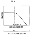
さらに、図6は深さdとピン穴の疲労強度の関係を表した図である。図6に示したように、ビビリマーク31の深さdが一定値を超えると疲労強度が低下していくことが判った。従って、疲労強度に影響しない範囲で基準深さDを設定し、ビビリマーク31の基準深さをD(例えば25μm)とした場合、基準深さDに相当する基準幅(しきい値)Wが図5の関係から得られるので、ピン穴8の観察画像におけるビビリマーク31の最大幅wを基準幅Wと比較する。
Further, FIG. 6 is a diagram showing the relationship between the depth d and the fatigue strength of the pin hole. As shown in FIG. 6, it was found that the fatigue strength decreases when the depth d of the
本工程S5では、このようにビビリマークの幅寸法wと深さdの相関関係の下、ビビリマーク31の幅寸法wの計測結果がしきい値(基準幅W)以上である場合、前記ビビリマークの深さが許容値以上であると判定する。ビビリマーク31の幅寸法wで深さdを計測するので、取得された観察像からビビリマーク31の深さが判別でき、粗さ測定が不要であるため、ビビリマーク31の研磨補修の必要性を迅速に評価することができる。
In this step S5, when the measurement result of the width dimension w of the
w<Wであれば、ビビリマーク31はピン穴8の疲労強度には影響しないとして図3の一連の手順を終了する。ビビリマーク31が確認されてもしきい値に満たない(強度上影響の少ない)ビビリマーク31である場合にその後の工程を省略することにより、不要な作業を省略することができる。一方、w≧Wであればそのビビリマーク31がピン穴8の疲労強度低下をもたらす可能性があるとして、補修の研磨工程S6に手順を移行する。
If w <W, the
なお、工程S5の判定は、画像処理・表示装置45の表示画面に表示される観察像を基に作業者が判定することができる。或いは、画像処理・表示装置45の画像処理機能やスケール機能により、ビビリマーク31の幅寸法wの計測(ビビリマーク31の深さdの計測)が自動的になされるようにしても良い。さらには、幅寸法wの計測結果をしきい値Wと比較して、しきい値W以上である場合に次工程に手順を移す必要があると判定するプログラムを画像処理・表示装置45に予め格納しておき、画像処理・表示装置45によって工程S5の判定が自動的になされるようにしても良い。
The determination in step S5 can be made by the operator based on the observation image displayed on the display screen of the image processing /
工程S6では、ピン穴8にグラインダ研磨などを施し、ビビリマーク31の凹凸を除去もしくは浅くする。図7(a)は研磨装置をピン穴8に挿入した状態を表した模式図、図7(b)は図7(a)中のVIIb−VIIb断面による断面図である。研磨装置70は、エア駆動式の回転駆動装置(図示せず)の先に回転シャフト71を装着し、回転シャフト71の先端部に短冊状の研磨ペーパー(研磨布)72がホイール状に複数枚取付けられた構造の器具を用いる。エア駆動により回転シャフト71を回転させ、ピン穴8に挿入することにより、研磨ペーパー72がピン穴8内面を研磨し、ビビリマーク31の凹凸を除去もしくは浅くすることができる。研磨後、再び工程S3に戻ってピン穴8内面の観察を実施し、ビビリマーク31の有無、深さを再び判定する。
In step S6, the
工程S6の研磨は、研磨対象位置に配置されたタービン動翼2をタービンロータ3から取外した状態で行ってもよい。この場合、研磨装置70の寸法のとり合いがピン穴8内部形状に制約される必要がなくなり、使用できる研磨装置の選択の幅が広がるメリットがある。
The polishing in step S6 may be performed in a state where the
以上、上記の工程を行う検査システムを使用することにより、ビビリマーク31のピン穴8の軸方向にとった幅寸法wを計測して深さdに換算するので、計測器(本例の場合、スコープ本体41)の計測方向がピン穴8の軸方向になるため計測器の設置が容易であり、迅速にビビリマーク31の深さを測定することができ、表面仕上げ加工を迅速化することが可能である。また、作業工数に負担をかけることなく確実にタービン動翼の連結部の強度信頼性を高めることができる。
As described above, since the width dimension w taken in the axial direction of the
なお、上記の検査システムは、図1(a)と異なるピン結合方式のタービン動翼とタービンロータであっても当然に適用可能である。例えば、図1(b)に示すような翼フォーク135とロータフォーク137とを互いに嵌め合せた状態で、タービン回転軸方向に連通する結合ピン139によって結合されるフォーク−ピン結合方式のピン穴138の検査に適用できる。
Note that the above inspection system can naturally be applied even to a turbine blade and turbine rotor of a pin coupling type different from those in FIG. For example, in a state where the
また、タービン動翼とタービンロータとを連結するピンのピン穴8の内面に限らず、その他の加工仕上げ面に発生するビビリマークの検査にも適用可能である。タービンに適用する場合には、例えば、タービン連結部のタービン動翼の翼根部をタービンロータに嵌め合わせるいわゆるフック結合部に適用できる。フック結合部では、タービン動翼にかかる遠心力により、翼根部側のフックのくびれ部やタービンロータ側のフック溝のくびれ部にタービン径方向の引張荷重が作用する。したがって、強度向上のためくびれ部分の粗さを低く抑えることが望ましい。フックやフック溝は、エンドミル等で仕上げ加工され、条件によってはビビリが発生する可能性がある。このような場合にも本実施例を適用できる。
Moreover, it is applicable not only to the inner surface of the
さらに本実施例は、タービン動翼の連結部など、機械部品の連結部分に限らず、その他の機械部品の加工面等、ビビリマークが発生しそれによる疲労強度低下が懸念されるケースに広く適用可能である。 Furthermore, the present embodiment is widely applied to cases where chatter marks are generated and the fatigue strength may be reduced due to the machined surfaces of other machine parts, such as the connection parts of turbine blades and other machine parts. Is possible.
本実施例は、実施例1の工程S3−S5でマイクロスコープ40により加工仕上げ面を観察しビビリマーク31の深さを評価する代わりに、図8に示したような粗さ計(例えば触針式)80を用いる例である。図8(a)は粗さ計をピン穴8に挿入した状態を表す模式図、図8(b)は図8(a)中のVIIIb−VIIIb断面による断面図、図8(c)はピン穴8の中心軸に直交する面で切ったビビリマーク31の断面図である。アームがピン穴8の軸方向に移動するように粗さ計80を設置し、この粗さ計80を用いて回転工具の回転軸方向(ピン穴8の軸方向)に加工仕上げ面の粗さを計測する。粗さ計、特に触針式などでビビリマークの一点を測定する装置を使用する場合には、同一箇所もしくは左右に位置を変えて、複数回の測定を行ってもよい。
In this embodiment, instead of observing the processed finish surface by the
例えば図8(c)のように幅寸法w3のビビリマーク31がある場合、粗さ計80により得られる粗さ曲線には、幅寸法w3の局所的な窪みが現れるため、得られた粗さ曲線を基に、ビビリマーク31の有無の検知及び検知されたビビリマーク31の幅寸法wの計測が可能であり、基準幅Wとの比較判定が容易である。このように、粗さ計を仕様した検査システムを使用する場合も、実施例1と同様の効果が得られる。また、粗さ計80は、加工現場で一般に利用されており、それをそのまま用いることができるので、検査システムの構築が容易である。
For example, when there is a
なお、計測対象のタービン動翼2をタービンロータ3から取外した状態で検査してもよい。この場合、粗さ計80の寸法のとり合いがピン穴8内部形状に制約される必要がなくなり、使用できる粗さ計の選択の幅が広がる。
In addition, you may test | inspect in the state which removed the
本実施例は、実施例1の工程S3−S5でマイクロスコープ40により加工仕上げ面を観察する代わりに、型取り剤(転写手段)90を用いて仕上げ面を観察した例である。図9(a)は型取り剤をピン穴8の内面に塗布した状態を表す模式図、図9(b)は図9(a)中のIXb−IXb断面による断面図、図9(c)は転写後の型取り剤を模式的に表した斜視図である。
In this embodiment, instead of observing the finished work surface with the
型取り剤90としては、塗布後に固まる液体シリコンや粘土状の型取り材等を始め、一般に使用されている型取り剤が使用できる。例えば液体シリコンを用いる場合、ピン穴8内面の目的の箇所(50°〜130°の領域B)に型取り材90を塗布し、固まったら剥がして平たくならし、型取り剤90に転写されたピン穴8の内面転写像(表面模様)を観察する。型取り剤90の内面転写像にビビリマーク31が確認されたら、その幅寸法wを内面転写像上でノギスやメジャー、物差し等で計測し、幅寸法wからビビリマーク31の深さを計測する。型取り剤90の転写模様を基に、ビビリの発生を検知又はビビリマークの幅寸法を計測することによっても、同様の効果を得ることができ、また検査システムの構築も容易である。
As the mold taking agent 90, generally used mold taking agents such as liquid silicon which is solidified after application, clay-like mold taking material and the like can be used. For example, when liquid silicon is used, the mold taking material 90 is applied to a target location (area B of 50 ° to 130 °) on the inner surface of the
なお、検査対象のタービン動翼2をタービンロータ3から取外した状態で検査してもよい。この場合、ピン穴8円筒内面が開放されるため、型取り作業がし易くなるメリットがある。
The
本実施例は、実施例1の工程S3−S5でマイクロスコープ40により加工仕上げ面を観察する代わりに、粘着テープ(転写手段)100を用いた例である。図10(a)は粘着テープをピン穴8の内面に貼付した状態を表す模式図、図10(b)は図10(a)中のXb−Xb断面による断面図、図10(c)は転写後の粘着テープを模式的に表した斜視図である。
The present embodiment is an example in which an adhesive tape (transfer means) 100 is used instead of observing the finished surface with the
粘着テープ100としては、一般に使用されている粘着テープが使用できる。本実施の形態の場合、ピン穴8内面の目的の箇所(50°〜130°の領域B)に粘着テープ100を貼付後、剥がして平たくならし、粘着テープ100の表面に転写されたピン穴8の内面転写像(表面模様)を観察する。粘着テープ100の内面転写像にビビリマーク31が確認されたら、その幅寸法wを内面転写像上でノギスやメジャー,物差し等で計測し、幅寸法wからビビリマーク31の深さを計測する。
As the
本実施の形態のように、粘着テープ100の転写模様を基に、ビビリの発生を検知又はビビリマークの幅寸法を計測することによっても、同様の効果を得ることができ、また検査システムの構築も容易である。また、一枚の粘着テープ100で施工する場合、ピン穴8の内面から粘着テープ100を剥がす際に残存物を残す心配が少ないのも利点である。
As in the present embodiment, the same effect can be obtained by detecting the occurrence of chatter or measuring the width dimension of the chatter mark based on the transfer pattern of the
なお、検査対象のタービン動翼2をタービンロータ3から取外した状態で検査してもよい。この場合、ピン穴8円筒内面が開放されるため、作業がし易くなるメリットがある。
The
本実施例は、実施例1の工程S6で研磨ペーパー72により加工仕上げ面を研磨する代わりに、砥粒付き研磨ブラシ110を用いた例である。
In this embodiment, instead of polishing the finished surface with the polishing
図11(a)は第5の実施の形態で用いる研磨装置をピン穴8に挿入した状態を表した模式図、図11(b)は図11(a)中のXIb−XIb断面による断面図である。砥粒付き研磨ブラシ110は、図7の回転シャフト71と実質同様の回転シャフト111の先端部に、砥石玉112を先端につけたブラシ113が多数取付けられた構造である。この砥粒付き研磨ブラシ110を用い、回転シャフト111を回転させてピン穴8に挿入することにより、砥石玉112によってピン穴8の内面が研磨され、ビビリマーク31の凹凸を除去もしくは浅くすることができる。この場合も第1の実施の形態と同様の効果が得られる。また研磨ペーパー72・砥粒付き研磨ブラシ110とも、既存の設備の流用が可能であり検査システムの構築が容易である。
FIG. 11A is a schematic diagram illustrating a state where the polishing apparatus used in the fifth embodiment is inserted into the
なお、工程S6においては、研磨対象位置のタービン動翼2をタービンロータ3から取外した状態で研磨してもよい。この場合、砥粒付き研磨ブラシ110の寸法のとり合いがピン穴8内部形状に制約される必要がなくなり、使用できる研磨装置の選択の幅が広がるメリットがある。
In step S6, polishing may be performed with the
本実施例では、実施例1の観察手段,計測手段,判定手段を有する検査システムに、仕上げ加工手段を設けた例を説明する。 In the present embodiment, an example will be described in which finishing processing means is provided in the inspection system having the observation means, measurement means, and determination means of the first embodiment.
図12に、本実施例の加工仕上げ面の検査方法の手順をフローチャートで表す。図12に示した工程S11,S12,S13,S14,S15,S16は、それぞれ第1の実施の形態の工程S1,S2,S6,S3,S4,S5と実質同じである。本実施例が実施例1の方法と相違する点は、工程S12でリーマ加工時のトルクの急上昇(ビビリ発生の疑い)を検知した時点で、仕上げ加工は不合格と判定し、加工仕上げ面の観察やビビリマークの計測を行わずに工程S13において仕上げ加工面を研磨する点である。
FIG. 12 is a flowchart showing the procedure of the method for inspecting the finished surface of the working example. Steps S11, S12, S13, S14, S15, and S16 shown in FIG. 12 are substantially the same as steps S1, S2, S6, S3, S4, and S5 of the first embodiment, respectively. The difference between this embodiment and the method of
その後、工程S14で仕上げ加工面を観察し、工程S15にてビビリマークが認められなければ一連の仕上げ加工手順を終了する。一方、ビビリマークが認められた場合には、工程S15から工程S16に手順を移してビビリマークの幅寸法を計測ししきい値Wと比較する。なお、この工程S16には、厳密にはビビリマークの幅寸法を計測する工程と、計測結果をしきい値Wと比較する工程が含まれる。その結果、合格であれば手順を終了し、不合格であれば工程S13に手順を戻す。本実施の形態によっても、実施例1とほぼ同様の効果が得られる。 Thereafter, the finished surface is observed in step S14. If no chatter mark is recognized in step S15, the series of finishing steps is terminated. On the other hand, when the chatter mark is recognized, the procedure is shifted from step S15 to step S16, the width dimension of the chatter mark is measured, and compared with the threshold value W. Strictly speaking, the step S16 includes a step of measuring the width dimension of the chatter mark and a step of comparing the measurement result with the threshold value W. As a result, if it passes, the procedure ends, and if it fails, the procedure returns to step S13. Also according to the present embodiment, substantially the same effect as in Example 1 can be obtained.
本実施例においては、実施例1の実施の形態の手順(図3)と比較して、S12で発生が疑われたビビリマークが研磨を必要とする不良なものであった場合、最初の研磨工程までの観察・検査の手順が省略される。例えば、経験上、もしくは実施例1などの検査方法により機械加工中のトルク急上昇に伴うビビリマークが補修を要するものであることが多いことが把握されている場合には、本実施の形態の手順を採用することにより全体の作業を効率化することができる。反対に、機械加工中のトルク急上昇に伴うビビリマークが補修するほどでもない場合が多いようであれば、実施例1の手順を採用することでより作業効率が向上する。 In this example, as compared with the procedure of the embodiment of Example 1 (FIG. 3), when the chatter mark suspected of being generated in S12 is a defective one requiring polishing, the first polishing is performed. The observation and inspection procedures up to the process are omitted. For example, when it is known from experience or that the chatter mark accompanying the sudden increase in torque during machining is often required to be repaired by an inspection method such as Example 1, the procedure of the present embodiment By adopting, the overall work can be made efficient. On the other hand, if there are many cases where the chatter marks accompanying the sudden increase in torque during machining are not repaired, the work efficiency is further improved by adopting the procedure of the first embodiment.
また、機械加工中のトルクとビビリマークの不良率の関係を事前に検討し、トルクによるビビリ発生の推定の工程の後、研磨工程に移行するか(図12のフローを実行するか)観察工程に移行するか(図3のフローを実行するか)を柔軟に選択することとしてもよい。その結果、さらに作業効率を向上させることができる。 In addition, the relationship between the torque during machining and the defect rate of chatter marks is examined in advance, and the process of estimating whether chatter occurs due to torque and then shifting to a polishing process (whether to execute the flow of FIG. 12) observation process It may be possible to flexibly select whether to shift to (execute the flow of FIG. 3). As a result, the working efficiency can be further improved.
本実施例は、実施例1の工程S1、実施例6の工程S11でリーマ加工時のトルクを測定・記録する代わりに、加工機械に振動センサを取付け回転工具(リーマ棒)の振動を測定・記録する例である。ビビリ振動の振動数は特有であるため、加工中の回転工具の振動数を計測することにより、ビビリマークの発生の有無を推定することができる。この場合、振動を直接観測するので、トルク測定よりもビビリマークの発生の推定が正確になる。
In this embodiment, instead of measuring and recording the torque during reamer processing in step S1 of
図13は本実施例の検査システムの構成例を示す概略図である。図13に示したタービン動翼連結部1のタービン植込み部5及びロータ植込み部7には、ピン穴8が穿設されている。リーマ加工機120には、リーマ棒121,リーマ棒121を回転駆動部に固定するチャック部122,チャック部122の回転軸123,回転軸123を支持する軸受124,回転軸123を回転駆動させる図示しない駆動装置、回転軸123及び軸受124を内蔵し回転軸123の軸方向に駆動するアーム127,アーム127を支持する架台128を備えており、リーマ棒121でピン穴8の内面を仕上げ加工する。なお、既出図面と同様の部分には同符号を付して説明を省略する。
FIG. 13 is a schematic diagram showing a configuration example of the inspection system of this embodiment. A
軸受124には加速度検出器125を取付けられており、加速度検出器125の検出信号を振動分析・表示装置126に入力する。振動分析・表示装置126では、加速度検出器125からの入力信号を基に、ピン穴8の内面仕上げ加工時のリーマ棒121の振動を計測・記録し、それを自らのモニタ画面に表示する。
An
図14は振動分析・表示装置126による振動計測の結果の一例を表す図である。図14では、横軸に振動周波数(Hz)、縦軸に振動強度(dB)をとっている。図14において、振動周波数領域aはビビリ振動に特有の周波数帯である。加工中のリーマ棒121の振動数を計測した結果、図示したように振動数領域aにピークが認められる場合、ビビリ振動発生が推定される。振動数領域aでの振動があるかどうかの判定を工程S2(図3)又は工程S12(図12)で実施し、ビビリ振動発生が推定された場合には工程S3(図3)又は工程S13(図12)に手順を移す。
FIG. 14 is a diagram illustrating an example of a result of vibration measurement by the vibration analysis /
工程S2,S12の判定は、振動分析・表示装置126の表示画面に表示される計測結果を基に、作業者が判定することができる。もしくは、振動周波数領域aの振動が計測された場合にその振動強度をしきい値と比較して、しきい値以上である場合にビビリ発生の疑いがあると判定するプログラムを振動分析・表示装置126に予め格納しておき、振動分析・表示装置126によって自動判定されるようにしても良い。
The determination of steps S2 and S12 can be made by the operator based on the measurement result displayed on the display screen of the vibration analysis /
1 タービン動翼連結部
2 タービン動翼
3 タービンロータ
4 翼部
5 翼植込み部
6 ロータディスク
7 ロータ植込み部
8 ピン穴
31 ビビリマーク
40 マイクロスコープ
41 スコープ本体
45 画像処理・表示装置
70 研磨装置
71,111 回転シャフト
72 研磨ペーパー
80 粗さ計
90 型取り剤
100 粘着テープ
110 砥粒付き研磨ブラシ
112 砥石玉
113 ブラシ
120 リーマ加工機械
121 リーマ棒
123 回転軸
125 加速度検出器
126 振動分析・表示装置
d ビビリマークの深さ
w ビビリマークの幅寸法
W しきい値
DESCRIPTION OF
Claims (22)
前記加工仕上げ面を観察する観察手段と、前記観察手段でビビリマークの発生が確認された場合に前記ビビリマークの前記回転工具の回転軸方向にとった幅寸法を計測する計測手段と、計測結果がしきい値以上である場合にビビリマークの深さが許容値以上であると判定するビビリ深さ判定手段を有する加工仕上げ面の検査システム。 In the inspection system of the machined surface machined by a rotary tool,
Observation means for observing the processed finish surface, measurement means for measuring the width dimension of the chatter mark taken in the direction of the rotation axis of the rotating tool when occurrence of chatter marks is confirmed by the observation means, and measurement results An inspection system for a finished surface having chatter depth determining means for determining that the depth of the chatter mark is equal to or greater than an allowable value when the value of the chatter mark is equal to or greater than a threshold value.
前記ビビリ深さ判定手段で前記ビビリマークの深さが許容値以上であると判定された場合に加工仕上げ面を研磨する研磨手段を有することを特徴とする加工仕上げ面の検査システム。 The processing finished surface inspection system according to claim 1,
A processing finish surface inspection system comprising polishing means for polishing a work finish surface when the chatter depth determination means determines that the depth of the chatter mark is greater than an allowable value.
機械加工中の回転工具のトルク又は機械振動を計測しビビリ振動の発生を推定するビビリ振動発生推定手段を有することを特徴とする加工仕上げ面の検査システム。 The processing finished surface inspection system according to claim 1,
A machining finished surface inspection system comprising chatter vibration generation estimation means for measuring the torque or mechanical vibration of a rotating tool during machining and estimating the occurrence of chatter vibration.
前記ビビリ振動発生推定手段によりビビリ振動の発生が推定された場合に加工仕上げ面を研磨する研磨手段を有することを特徴とする加工仕上げ面の検査システム。 The processing finished surface inspection system according to claim 4,
A processing finish surface inspection system comprising polishing means for polishing a finish surface when occurrence of chatter vibration is estimated by the chatter vibration generation estimation means.
回転工具により機械加工されたタービン動翼の連結部のピン穴の内面の加工仕上げ面に用いられることを特徴とする加工仕上げ面の検査システム。 The processing finished surface inspection system according to claim 1,
An inspection system for a finished surface that is used for a finished surface of an inner surface of a pin hole of a connecting portion of a turbine rotor blade machined by a rotary tool.
回転工具によりリーマ穴加工された部材の加工仕上げ面に用いられることを特徴とする加工仕上げ面の検査システム。 The processing finished surface inspection system according to claim 1,
An inspection system for a machined surface that is used for a machined surface of a member that has been reamed by a rotary tool.
前記加工仕上げ面を観察し、ビビリマークの有無を判断する観察工程と、
前記観察工程でビビリマークが確認された場合に、ビビリマークの幅寸法を前記回転工具の回転軸方向で計測する計測工程と、
前記計測工程で計測されたビビリマークの幅寸法がしきい値以上である場合に、前記ビビリマークの深さが許容値以上であると判定するビビリ深さ判定工程と、を有することを特徴とする加工仕上げ面の検査方法。 In the inspection method of the machined surface machined by a rotary tool,
An observation step of observing the processed finish surface and determining the presence or absence of chatter marks;
When the chatter mark is confirmed in the observation step, a measurement step of measuring the width dimension of the chatter mark in the rotation axis direction of the rotary tool;
And a chatter depth determination step of determining that the depth of the chatter mark is greater than or equal to an allowable value when the width dimension of the chatter mark measured in the measurement step is greater than or equal to a threshold value. Inspection method for finished surface to be processed.
前記ピン穴の加工仕上げ面を観察し、ビビリマークの有無を判断する観察工程と、
前記観察工程でビビリマークが確認された場合に、ビビリマークの幅寸法を前記回転工具の回転軸方向で計測する計測工程と、
前記計測工程で計測されたビビリマークの幅寸法がしきい値以上である場合に、前記ビビリマークの深さが許容値以上であると判定するビビリ深さ判定工程と、を有することを特徴とする加工仕上げ面の検査方法。 In the inspection method of the finished surface of the pin hole of the connecting part of the turbine rotor blade machined by a rotary tool,
An observation step of observing the finished surface of the pin hole and determining the presence or absence of a chatter mark;
When the chatter mark is confirmed in the observation step, a measurement step of measuring the width dimension of the chatter mark in the rotation axis direction of the rotary tool;
And a chatter depth determination step of determining that the depth of the chatter mark is greater than or equal to an allowable value when the width dimension of the chatter mark measured in the measurement step is greater than or equal to a threshold value. Inspection method for finished surface to be processed.
前記ビビリ深さ判定工程で前記ビビリマークの深さが許容値以上であると判定された場合に、当該ビビリマークが発生している加工仕上げ面を研磨する研磨工程を有し、
研磨工程後に前記観察工程,計測工程,ビビリ深さ判定工程を繰り返すことを特徴とする加工仕上げ面の検査方法。 In the method for inspecting a work finish surface according to claim 12 or 13,
When it is determined in the chatter depth determination step that the depth of the chatter mark is greater than or equal to an allowable value, there is a polishing step of polishing the finished surface where the chatter mark is generated,
A method for inspecting a finished surface, wherein the observation step, the measurement step, and the chatter depth determination step are repeated after the polishing step.
前記研磨工程は、砥粒付き研磨ブラシ又は研磨布ホイールで加工仕上げ面を研磨する工程であることを特徴とする加工仕上げ面の検査方法。 The method for inspecting a work finish surface according to claim 14,
The polishing step is a step of polishing the finished surface with a polishing brush with abrasive grains or a polishing cloth wheel.
前記機械加工中の前記回転工具のトルク又は機械振動を計測し、ビビリ振動の発生を推定するビビリ振動発生推定工程を有し、前記ビビリ振動発生推定工程でビビリ振動の発生が推定された場合に前記観察工程を行うことを特徴とする加工仕上げ面の検査方法。 In the method for inspecting a work finish surface according to claim 12 or 13,
When there is a chatter vibration generation estimation step of measuring the torque or mechanical vibration of the rotating tool during the machining and estimating the occurrence of chatter vibration, and when the occurrence of chatter vibration is estimated in the chatter vibration generation estimation step A method for inspecting a finished surface, wherein the observation step is performed.
前記機械加工中の前記回転工具のトルク又は機械振動を計測し、ビビリ振動の発生を推定するビビリ振動発生推定工程と、前記ビビリ振動発生推定工程でビビリ振動の発生が推定された場合に加工仕上げ面を研磨する研磨工程とを有し、前記研磨工程の後に、前記観察工程を行うことを特徴とする加工仕上げ面の検査方法。 In the method for inspecting a work finish surface according to claim 12 or 13,
Measuring the torque or mechanical vibration of the rotating tool during the machining and estimating the occurrence of chatter vibration, and finishing when the occurrence of chatter vibration is estimated in the chatter vibration occurrence estimation step And a polishing step for polishing the surface, and the observation step is performed after the polishing step.
前記研磨工程は、砥粒付き研磨ブラシ又は研磨布ホイールで加工仕上げ面を研磨する工程であることを特徴とする加工仕上げ面の検査方法。 The method for inspecting a work finish surface according to claim 17,
The polishing step is a step of polishing the finished surface with a polishing brush with abrasive grains or a polishing cloth wheel.
前記観察工程は、加工仕上げ面をマイクロスコープで観察する工程であり、
前記計測工程は前記マイクロスコープによる観察像のスケール機能によるビビリマークの幅寸法を計測する工程であることを特徴とする加工仕上げ面の検査方法。 In the method for inspecting a work finish surface according to claim 12 or 13,
The observation step is a step of observing the processed finish surface with a microscope,
The method for inspecting a finished surface, wherein the measuring step is a step of measuring a width dimension of a chatter mark by a scale function of an observation image by the microscope.
前記観察工程は、粗さ計で前記回転工具の回転軸方向の加工仕上げ面の粗さを計測する工程を有し、
前記計測工程は得られた粗さ曲線を基にビビリマークの幅寸法を計測することを特徴とする加工仕上げ面の検査方法。 In the method for inspecting a work finish surface according to claim 12 or 13,
The observation step has a step of measuring the roughness of the machining finish surface in the rotation axis direction of the rotary tool with a roughness meter,
The measuring step includes measuring a width dimension of a chatter mark based on the obtained roughness curve, and a method for inspecting a finished surface.
前記観察工程は転写手段に加工仕上げ面の表面の模様を転写する工程を有し、
前記計測工程は前記転写手段に転写された模様を基にビビリマークの幅寸法を計測する工程であることを特徴とする加工仕上げ面の検査方法。 In the method for inspecting a work finish surface according to claim 12 or 13,
The observing step includes a step of transferring the pattern of the finished surface to the transfer means,
The method for inspecting a finished surface, wherein the measuring step is a step of measuring a width dimension of a chatter mark based on a pattern transferred to the transfer means.
前記加工仕上げ面は、リーマ穴加工されていることを特徴とする加工仕上げ面の検査方法。 In the method for inspecting a work finish surface according to claim 12 or 13,
A method for inspecting a finished surface, wherein the finished surface is reamer-holed.
Priority Applications (1)
| Application Number | Priority Date | Filing Date | Title |
|---|---|---|---|
| JP2009154525A JP5171743B2 (en) | 2009-06-30 | 2009-06-30 | Finished surface inspection system and inspection method |
Applications Claiming Priority (1)
| Application Number | Priority Date | Filing Date | Title |
|---|---|---|---|
| JP2009154525A JP5171743B2 (en) | 2009-06-30 | 2009-06-30 | Finished surface inspection system and inspection method |
Publications (2)
| Publication Number | Publication Date |
|---|---|
| JP2011012963A JP2011012963A (en) | 2011-01-20 |
| JP5171743B2 true JP5171743B2 (en) | 2013-03-27 |
Family
ID=43592039
Family Applications (1)
| Application Number | Title | Priority Date | Filing Date |
|---|---|---|---|
| JP2009154525A Expired - Fee Related JP5171743B2 (en) | 2009-06-30 | 2009-06-30 | Finished surface inspection system and inspection method |
Country Status (1)
| Country | Link |
|---|---|
| JP (1) | JP5171743B2 (en) |
Families Citing this family (3)
| Publication number | Priority date | Publication date | Assignee | Title |
|---|---|---|---|---|
| US8814632B2 (en) * | 2011-09-30 | 2014-08-26 | Apple Inc. | Scribing for polishing process validation |
| CN112809462B (en) * | 2019-11-18 | 2024-04-09 | 株式会社捷太格特 | Flutter Evaluation System |
| CN119197442B (en) * | 2024-11-23 | 2025-03-18 | 山西吸睛博远科技有限公司 | A flatness detection device for building wood processing |
Family Cites Families (6)
| Publication number | Priority date | Publication date | Assignee | Title |
|---|---|---|---|---|
| JPH02136710A (en) * | 1988-11-16 | 1990-05-25 | Mitsubishi Heavy Ind Ltd | Measuring method for corrosion pit |
| JPH0372211A (en) * | 1989-08-11 | 1991-03-27 | Hitachi Ltd | Analyzing apparatus of shape of inner wall of minute hole |
| JPH0777416A (en) * | 1993-09-08 | 1995-03-20 | Tipton Mfg Corp | Surface roughness measuring method and measuring device with neural network |
| JPH1177532A (en) * | 1997-09-09 | 1999-03-23 | Sumitomo Metal Ind Ltd | Rolling roll grinding equipment |
| JP3846542B2 (en) * | 1999-04-06 | 2006-11-15 | 株式会社東京精密 | Automatic dimension measuring device with roundness measurement function |
| JP2006208347A (en) * | 2004-02-25 | 2006-08-10 | Jfe Steel Kk | Surface defect detector, grinding device, surface defect detection method and surface defect detection program for reduction roll, and reduction roll grinding method |
-
2009
- 2009-06-30 JP JP2009154525A patent/JP5171743B2/en not_active Expired - Fee Related
Also Published As
| Publication number | Publication date |
|---|---|
| JP2011012963A (en) | 2011-01-20 |
Similar Documents
| Publication | Publication Date | Title |
|---|---|---|
| US9864362B2 (en) | Method for setting and/or monitoring operating parameters of a workpiece processing machine | |
| CA2818726C (en) | A method for measuring geometry deformations of a turbine component | |
| JP4767148B2 (en) | Rolling bearing remaining life diagnosis method using normal database, remaining life diagnosis system, and computer program used for remaining life diagnosis | |
| EP2251124B1 (en) | Long shaft inner surface processing apparatus and method of processing | |
| JP6499946B2 (en) | Machine tool bearing diagnostic device | |
| WO2008117765A1 (en) | Abnormality diagnostic method and device of extremely low speed rotary machine | |
| KR20110086120A (en) | Vibration analysis method and apparatus, sample database and use of sample database for this | |
| JP5171743B2 (en) | Finished surface inspection system and inspection method | |
| JP5655531B2 (en) | Friction and wear test equipment | |
| JP2003019531A (en) | Deep part form rolling device of recess and radius of crank shaft journal bearing | |
| CN101086202A (en) | On-service petroleum drill pipe detection and classification evaluation method | |
| JP2009180722A (en) | Support method for optimal maintenance time determination of object facility, computer program, and support device for optimal maintenance time determination of object facility | |
| JP5531257B2 (en) | Turbine blade flaw detection method | |
| EP1407854A2 (en) | Method for machining a surface and simultaneously measuring parameters of the surface being machined | |
| JP2015101991A (en) | Inspection method of turbine rotor | |
| KR20150088925A (en) | Using a sample of large bearings precision measurement system | |
| TWI855550B (en) | Method and device for measuring the depth of a damaged layer at a wafer edge | |
| Seif et al. | Deformation and strain fields in pin specimens in sliding contact by laser speckle and metallographic techniques | |
| JP6373233B2 (en) | Semiconductor wafer processing damage evaluation method | |
| CN111426259B (en) | A detection device and method for medium and large aperture parts | |
| JP7095375B2 (en) | Bearing abnormality diagnosis method and bearing abnormality diagnosis system | |
| CN219935747U (en) | Circular saw blade detection equipment | |
| JP4049985B2 (en) | Ultrasonic flaw detection apparatus and method | |
| JP2020185626A (en) | Measurement system for measuring abrasive grain distribution of grinding wheel surface and grinder provided with the same | |
| KR101409199B1 (en) | Machine Tool Spindle precision measuring device |
Legal Events
| Date | Code | Title | Description |
|---|---|---|---|
| A621 | Written request for application examination |
Free format text: JAPANESE INTERMEDIATE CODE: A621 Effective date: 20110704 |
|
| A977 | Report on retrieval |
Free format text: JAPANESE INTERMEDIATE CODE: A971007 Effective date: 20121122 |
|
| TRDD | Decision of grant or rejection written | ||
| A01 | Written decision to grant a patent or to grant a registration (utility model) |
Free format text: JAPANESE INTERMEDIATE CODE: A01 Effective date: 20121127 |
|
| A61 | First payment of annual fees (during grant procedure) |
Free format text: JAPANESE INTERMEDIATE CODE: A61 Effective date: 20121225 |
|
| R151 | Written notification of patent or utility model registration |
Ref document number: 5171743 Country of ref document: JP Free format text: JAPANESE INTERMEDIATE CODE: R151 |
|
| FPAY | Renewal fee payment (event date is renewal date of database) |
Free format text: PAYMENT UNTIL: 20160111 Year of fee payment: 3 |
|
| S111 | Request for change of ownership or part of ownership |
Free format text: JAPANESE INTERMEDIATE CODE: R313111 |
|
| R350 | Written notification of registration of transfer |
Free format text: JAPANESE INTERMEDIATE CODE: R350 |
|
| R250 | Receipt of annual fees |
Free format text: JAPANESE INTERMEDIATE CODE: R250 |
|
| R250 | Receipt of annual fees |
Free format text: JAPANESE INTERMEDIATE CODE: R250 |
|
| LAPS | Cancellation because of no payment of annual fees |