JP5161395B1 - Vibration suppression device - Google Patents
Vibration suppression device Download PDFInfo
- Publication number
- JP5161395B1 JP5161395B1 JP2012250465A JP2012250465A JP5161395B1 JP 5161395 B1 JP5161395 B1 JP 5161395B1 JP 2012250465 A JP2012250465 A JP 2012250465A JP 2012250465 A JP2012250465 A JP 2012250465A JP 5161395 B1 JP5161395 B1 JP 5161395B1
- Authority
- JP
- Japan
- Prior art keywords
- piston
- cylinder
- vibration
- screw shaft
- working fluid
- Prior art date
- Legal status (The legal status is an assumption and is not a legal conclusion. Google has not performed a legal analysis and makes no representation as to the accuracy of the status listed.)
- Active
Links
- 230000001629 suppression Effects 0.000 title claims description 38
- 239000012530 fluid Substances 0.000 claims abstract description 61
- 238000006073 displacement reaction Methods 0.000 abstract description 21
- 239000010720 hydraulic oil Substances 0.000 description 57
- 230000000694 effects Effects 0.000 description 30
- 239000003921 oil Substances 0.000 description 29
- 238000013016 damping Methods 0.000 description 28
- 238000006243 chemical reaction Methods 0.000 description 9
- 230000002093 peripheral effect Effects 0.000 description 9
- 230000007935 neutral effect Effects 0.000 description 5
- XEEYBQQBJWHFJM-UHFFFAOYSA-N Iron Chemical compound [Fe] XEEYBQQBJWHFJM-UHFFFAOYSA-N 0.000 description 4
- 230000000149 penetrating effect Effects 0.000 description 4
- 230000006835 compression Effects 0.000 description 3
- 238000007906 compression Methods 0.000 description 3
- 235000012489 doughnuts Nutrition 0.000 description 3
- 230000005484 gravity Effects 0.000 description 2
- 229910052742 iron Inorganic materials 0.000 description 2
- 239000000463 material Substances 0.000 description 2
- 230000001360 synchronised effect Effects 0.000 description 2
- 229910000831 Steel Inorganic materials 0.000 description 1
- LYKJEJVAXSGWAJ-UHFFFAOYSA-N compactone Natural products CC1(C)CCCC2(C)C1CC(=O)C3(O)CC(C)(CCC23)C=C LYKJEJVAXSGWAJ-UHFFFAOYSA-N 0.000 description 1
- 230000012447 hatching Effects 0.000 description 1
- 238000002955 isolation Methods 0.000 description 1
- 239000010959 steel Substances 0.000 description 1
- 239000000725 suspension Substances 0.000 description 1
Images


Landscapes
- Vibration Prevention Devices (AREA)
- Vibration Dampers (AREA)
- Fluid-Damping Devices (AREA)
Abstract
【課題】構造物の変位を、作動流体を介して回転マスの回転運動に効率良く変換することができ、それにより、構造物の振動を適切に抑制することができる振動抑制装置を提供する。
【解決手段】振動抑制装置1は、作動流体HFが充填されたシリンダ2と、シリンダ2に対して軸線方向に移動可能なロッド3と、ロッド3に一体に固定され、ロッド3の移動に伴ってシリンダ2内を摺動する第1ピストン4と、第1ピストン4をバイパスするようにシリンダ2に接続されたバイパス通路11と、バイパス通路11内に回転可能に設けられ、バイパス通路11の軸線方向に延びるねじ軸15と、ねじ軸15にボールを介して螺合するナット17を有し、ねじ軸15に沿ってバイパス11通路内を摺動可能で、かつバイパス通路11に対して回転不能な第2ピストン16と、ねじ軸15に取り付けられた、回転可能な回転マス21と、を備える。
【選択図】図2Disclosed is a vibration suppressing device capable of efficiently converting a displacement of a structure into a rotational motion of a rotating mass via a working fluid, thereby appropriately suppressing vibration of the structure.
A vibration suppressing device 1 includes a cylinder 2 filled with a working fluid HF, a rod 3 movable in an axial direction with respect to the cylinder 2, a fixed integrally with the rod 3, and as the rod 3 moves. A first piston 4 that slides in the cylinder 2, a bypass passage 11 that is connected to the cylinder 2 so as to bypass the first piston 4, and is rotatably provided in the bypass passage 11. A screw shaft 15 extending in the direction, and a nut 17 screwed onto the screw shaft 15 via a ball. The screw shaft 15 can slide along the screw shaft 15 in the bypass 11 passage and cannot rotate with respect to the bypass passage 11. A second piston 16 and a rotatable rotating mass 21 attached to the screw shaft 15.
[Selection] Figure 2
Description
本発明は、構造物を含む系内の2つの部位の間に設けられ、当該構造物の振動を抑制するための振動抑制装置に関する。 The present invention relates to a vibration suppressing device that is provided between two parts in a system including a structure and suppresses vibration of the structure.
従来、この種の振動抑制装置として、例えば特許文献1に開示されたものが知られている。この振動抑制装置は、作動流体が充填されたシリンダと、シリンダに部分的に収容されるとともに、軸線方向に移動可能なロッドと、ロッドに一体に固定され、シリンダ内に摺動可能に設けられたピストンを備えている。また、シリンダには、ピストンをバイパスするように、バイパス通路が接続されており、バイパス通路の途中には、羽根車が設けられている。羽根車には、回転マスが連結されている。
Conventionally, what was disclosed by
以上の構成の従来の振動抑制装置は、車両のサスペンション装置として用いられる。車両の振動に伴い、外力がロッドに入力されると、ロッドが、シリンダに対して軸線方向に移動するとともに、ピストンが、シリンダ内を軸線方向に摺動する。これにより、バイパス通路内の作動流体の流動が生じることで、羽根車及び回転マスが一体に回転し、作動流体及び回転マスの慣性力が抵抗力として車両に作用することで、車両の振動が抑制される。 The conventional vibration suppression device having the above configuration is used as a vehicle suspension device. When an external force is input to the rod along with the vibration of the vehicle, the rod moves in the axial direction with respect to the cylinder, and the piston slides in the cylinder in the axial direction. As a result, the flow of the working fluid in the bypass passage causes the impeller and the rotating mass to rotate integrally, and the inertial force of the working fluid and the rotating mass acts on the vehicle as a resistance force, so that the vibration of the vehicle is reduced. It is suppressed.
上述したように、従来の振動抑制装置では、車両などの構造物の変位を作動流体の流れに変換し、さらに作動流体の流れが、羽根車で回転運動に変換され、回転マスに伝達される。このため、例えば、作動流体の流量が小さいときには、羽根車及び回転マスの回転量が不足しがちになり、それにより回転マスの慣性力が十分に得られないので、構造物の振動を適切に抑制することができないおそれがある。 As described above, in the conventional vibration suppression device, the displacement of a structure such as a vehicle is converted into a flow of working fluid, and the flow of the working fluid is further converted into rotational motion by the impeller and transmitted to the rotary mass. . For this reason, for example, when the flow rate of the working fluid is small, the amount of rotation of the impeller and the rotating mass tends to be insufficient, so that the inertial force of the rotating mass cannot be obtained sufficiently. There is a possibility that it cannot be suppressed.
本発明は、以上のような課題を解決するためになされたものであり、構造物の変位を、作動流体を介して回転マスの回転運動に効率良く変換することができ、それにより、構造物の振動を適切に抑制することができる振動抑制装置を提供することを目的とする。 The present invention has been made to solve the above-described problems, and the displacement of the structure can be efficiently converted into the rotational motion of the rotating mass via the working fluid. An object of the present invention is to provide a vibration suppressing device that can appropriately suppress the vibration of the vibration.
上記の目的を達成するために、請求項1に係る発明は、構造物を含む系内の2つの部位の間に設けられ、構造物の振動を抑制するための振動抑制装置であって、2つの部位の一方に連結されるとともに、作動流体が充填されたシリンダと、2つの部位の他方に連結され、シリンダに部分的に収容されるとともに、シリンダに対して軸線方向に移動可能なロッドと、ロッドに一体に固定され、ロッドの移動に伴ってシリンダ内を摺動する第1ピストンと、第1ピストンをバイパスするようにシリンダに接続されたバイパス通路と、バイパス通路内に回転可能に設けられ、バイパス通路の軸線方向に延びるねじ軸と、ねじ軸にボールを介して螺合するナットを有するとともに、ねじ軸に沿ってバイパス通路内を摺動可能で、かつバイパス通路に対して回転不能な第2ピストンと、ねじ軸に取り付けられた、回転可能な回転マスと、を備えることを特徴とする。
In order to achieve the above object, an invention according to
この構成によれば、地震などで構造物が振動し、構造物を含む系内の2つの部位の間で変位が生じると、この2つの部位の間の変位(以下「構造物の変位」という)が、シリンダ及びロッドに伝達される。これにより、ロッドが、シリンダに対して軸線方向に移動し、それに伴い、ロッドと一体の第1ピストンがシリンダ内を摺動することによって、シリンダ内及びシリンダに接続されたバイパス通路内の作動流体に、流動が生じる。 According to this configuration, when a structure vibrates due to an earthquake or the like and displacement occurs between two parts in the system including the structure, the displacement between the two parts (hereinafter referred to as “displacement of the structure”). ) Is transmitted to the cylinder and the rod. As a result, the rod moves in the axial direction with respect to the cylinder, and the first piston integrated with the rod slides in the cylinder accordingly, so that the working fluid in the cylinder and in the bypass passage connected to the cylinder is obtained. The flow occurs.
このバイパス通路内には、その軸線方向に延びるねじ軸が回転可能に設けられており、このねじ軸には、第2ピストンのナットがボールを介してねじ軸に螺合するとともに、回転可能な回転マスが取り付けられている。このように、これらのねじ軸、ナット及びボールは、ボールねじを構成しており、ナットは、ねじ軸に対して回転可能である。また、第2ピストンは、ねじ軸に沿ってバイパス通路内を摺動可能で、かつバイパス通路に対して回転不能である。 A screw shaft extending in the axial direction is rotatably provided in the bypass passage. The nut of the second piston is screwed onto the screw shaft via a ball and is rotatable on the screw shaft. A rotating mass is attached. Thus, these screw shafts, nuts, and balls constitute a ball screw, and the nuts are rotatable with respect to the screw shafts. Further, the second piston can slide in the bypass passage along the screw shaft and cannot rotate with respect to the bypass passage.
上述したようにバイパス通路内の作動流体に流動が生じると、第2ピストンは、流動する作動流体に押圧されることによって、バイパス通路内を摺動する。この場合、ねじ軸が回転可能であることと、第2ピストンのナットが、ねじ軸に対して回転可能でかつバイパス通路に対して回転不能であることから、第2ピストンがバイパス通路内を摺動するのに伴って、ねじ軸は回転マスとともに、バイパス通路に対して回転する。 As described above, when flow occurs in the working fluid in the bypass passage, the second piston slides in the bypass passage by being pressed by the flowing working fluid. In this case, since the screw shaft can rotate and the nut of the second piston can rotate with respect to the screw shaft and cannot rotate with respect to the bypass passage, the second piston slides in the bypass passage. As it moves, the screw shaft rotates with the rotating mass relative to the bypass passage.
以上のように、振動による構造物の変位は、ロッド及び第1ピストンを介して作動流体に伝達されるとともに、さらに第2ピストン及びねじ軸を介して回転マスに伝達されることにより、回転マスが回転する。したがって、作動流体の粘性減衰力(効果)と回転マスの回転慣性力(効果)によって、構造物の振動を抑制することができる。 As described above, the displacement of the structure due to the vibration is transmitted to the working fluid via the rod and the first piston, and further transmitted to the rotating mass via the second piston and the screw shaft, so that the rotating mass is Rotates. Therefore, the vibration of the structure can be suppressed by the viscous damping force (effect) of the working fluid and the rotational inertia force (effect) of the rotating mass.
この場合、前述した従来の場合と異なり、羽根車ではなく、ねじ軸、ナット及びボールから成るボールねじと第2ピストンを用いて、作動流体の流動を回転運動に変換するので、ねじ軸及びナットのリード角を適切に設定することにより、作動流体の流量が比較的小さいことで第2ピストンの移動量が比較的小さい場合でも、ねじ軸及び回転マスを十分に回転させることができる。以上のように、構造物の変位を、作動流体を介して回転マスの回転運動に効率良く変換でき、それにより、構造物の振動を適切に抑制することができる。 In this case, unlike the above-described conventional case, the flow of the working fluid is converted into rotational motion using a ball screw and a second piston, which are not an impeller, but a screw shaft, a nut and a ball. By appropriately setting the lead angle, the screw shaft and the rotation mass can be sufficiently rotated even when the flow rate of the working fluid is relatively small and the movement amount of the second piston is relatively small. As described above, the displacement of the structure can be efficiently converted into the rotational motion of the rotary mass via the working fluid, and thereby the vibration of the structure can be appropriately suppressed.
請求項2に係る発明は、請求項1に記載の振動抑制装置において、第2ピストンは、ナットに対して軸線方向の一方の側に設けられ、第1ピストンがシリンダの一方の側に摺動するのに伴って流動する作動流体に押圧される第1受圧部と、ナットに対して軸線方向の他方の側に設けられ、第1ピストンがシリンダの他方の側に摺動するのに伴って流動する作動流体に押圧される第2受圧部と、ナットと第1受圧部の間に設けられ、第1受圧部に作用する作動流体の押圧力をナットに伝達するための第1弾性体と、ナットと第2受圧部の間に設けられ、第2受圧部に作用する作動流体の押圧力をナットに伝達するための第2弾性体と、を有することを特徴とする。
The invention according to
この構成によれば、第1ピストンがシリンダの一方の側に摺動するのに伴って作動流体が流動したときに、流動する作動流体によって、第2ピストンの第1受圧部が押圧される。これとは逆に、第1ピストンがシリンダの他方の側に摺動するのに伴って作動流体が流動したときに、流動する作動流体によって、第2ピストンの第2受圧部が押圧される。また、第1受圧部に作用する作動流体の押圧力が、第1弾性体を介してナットに伝達されるとともに、第2受圧部に作用する作動流体の押圧力が、第2弾性体を介してナットに伝達される。 According to this configuration, when the working fluid flows as the first piston slides to one side of the cylinder, the first pressure receiving portion of the second piston is pressed by the flowing working fluid. On the contrary, when the working fluid flows as the first piston slides to the other side of the cylinder, the second pressure receiving portion of the second piston is pressed by the flowing working fluid. In addition, the pressing force of the working fluid acting on the first pressure receiving portion is transmitted to the nut via the first elastic body, and the pressing force of the working fluid acting on the second pressure receiving portion is transmitted via the second elastic body. Is transmitted to the nut.
以上の構成により、振動による構造物の往復動により第1ピストンがロッドとともにシリンダに対して軸線方向の一方の側及び他方の側に繰り返し摺動するときには、構造物の変位は、次のようにして回転マスに伝達される。 With the above configuration, when the first piston repeatedly slides with the rod on one side and the other side in the axial direction due to the reciprocation of the structure due to vibration, the displacement of the structure is as follows. Is transmitted to the rotating mass.
すなわち、第1ピストンが一方の側に摺動したときには作動流体、第1受圧部及び第1弾性体を介して、第1ピストンが他方の側に摺動したときには作動流体、第2受圧部及び第2弾性体を介して、ナットに伝達され、さらにねじ軸を介して回転マスに伝達される結果、回転マスが回転する。このように、振動による構造物の往復動に対して、作動流体、第1弾性体及び回転マスから成る付加振動系と、作動流体、第2弾性体及び回転マスから成る付加振動系が構成される。 That is, when the first piston slides to one side, the working fluid, the first pressure receiving portion, and the first elastic body, and when the first piston slides to the other side, the working fluid, the second pressure receiving portion, and As a result of being transmitted to the nut via the second elastic body and further transmitted to the rotating mass via the screw shaft, the rotating mass rotates. In this way, an additional vibration system composed of a working fluid, a first elastic body, and a rotating mass, and an additional vibration system composed of a working fluid, a second elastic body, and a rotating mass are configured for the reciprocation of the structure due to vibration. The
したがって、作動流体の粘性減衰係数や、第1弾性体のばね定数、第2弾性体のばね定数、回転マスの質量を設定することによって、上記の付加振動系の固有振動数を構造物の所望の固有振動数に同調(共振)させることができ、ひいては、構造物の振動をより適切に抑制することができる。 Therefore, by setting the viscous damping coefficient of the working fluid, the spring constant of the first elastic body, the spring constant of the second elastic body, and the mass of the rotating mass, the natural frequency of the additional vibration system is set to the desired value of the structure. It is possible to tune (resonate) with the natural frequency of the structure, and more appropriately suppress the vibration of the structure.
請求項3に係る発明は、請求項2に記載の振動抑制装置において、第1弾性体のばね定数及び第2弾性体のばね定数は、互いに異なる値に設定されていることを特徴とする。
The invention according to
一般に、構造物は、地震などにより振動したときに、必ずしも単一の固有振動数で振動するとは限らず、互いに異なる複数の固有振動数で、すなわち複数の振動モードで振動するのが通常である。これに対して、通常、一基のマスダンパ及び支持部材から成る一基の付加振動系の固有振動数は、ただ1つである。このため、構造物の複数の振動モードによる振動を適切に抑制すべく、構造物の複数の所望の固有振動数に付加振動系の固有振動数を同調させるには、構造物の複数の固有振動数に対応する複数の付加振動系を設けなければならず、ひいては、振動抑制装置の大型化及びコストの増大を招いてしまう。 In general, when a structure vibrates due to an earthquake or the like, it does not always vibrate at a single natural frequency, but usually vibrates at a plurality of different natural frequencies, that is, in a plurality of vibration modes. . On the other hand, normally, a single additional vibration system composed of a single mass damper and a supporting member has only one natural frequency. For this reason, in order to appropriately suppress the vibration of the structure due to the plurality of vibration modes, the natural frequency of the additional vibration system is tuned to the plurality of desired natural frequencies of the structure. A plurality of additional vibration systems corresponding to the number must be provided, which leads to an increase in the size and cost of the vibration suppression device.
本発明によれば、請求項2に係る発明の説明で述べた2つの付加振動系の一方及び他方をそれぞれ構成する第1及び第2弾性体のばね定数が、互いに異なる値に設定されている。したがって、これらの一方の付加振動系の固有振動数を、構造物の所望の1つの固有振動数に適切に同調させるとともに、他方の付加振動系の固有振動数を、構造物の他の所望の1つの固有振動数に適切に同調させることができる。すなわち、一方及び他方の付加振動系の固有振動数を、互いに異なる構造物の2つの所望の固有振動数にそれぞれ多重同調させることができる。これにより、作動流体や、回転マス、第1弾性体、第2弾性体などから成る一基の振動抑制装置によって、構造物の複数の振動モードによる振動を適切に抑制でき、ひいては、装置のさらなる小型化を図ることができる。
According to the present invention, the spring constants of the first and second elastic bodies constituting one and the other of the two additional vibration systems described in the description of the invention according to
請求項4に係る発明は、請求項2又は3に記載の振動抑制装置において、回転マスは、ねじ軸に取り付けられ、回転可能な第1回転マスと、第1回転マスに弾性体を介して取り付けられ、第1回転マスに対して回転可能な第2回転マスと、を有することを特徴とする。 According to a fourth aspect of the present invention, in the vibration suppressing device according to the second or third aspect, the rotating mass is attached to the screw shaft, the first rotating mass is rotatable, and the first rotating mass is interposed via an elastic body. And a second rotating mass that is attached and rotatable relative to the first rotating mass.
この構成によれば、回転マスが第1及び第2回転マスで構成され、第1回転マスは、ねじ軸に取り付けられており、第2回転マスは、弾性体を介して第1回転マスに取り付けられており、第1回転マスに対して回転可能である。このため、請求項1に係る発明の説明から明らかなように、振動による構造物の変位が、ロッド、第1ピストン、作動流体、及び第2ピストンを介してねじ軸に伝達され、さらに第1回転マスに伝達される結果、第1回転マスが回転する。また、第1回転マスが回転するのに伴い、第2回転マスが、第1回転マスに対して回転する。したがって、作動流体の粘性減衰効果及び第1回転マスの回転慣性効果に加え、第2回転マスの回転慣性効果によって、構造物の振動をより適切に抑制することができる。
According to this configuration, the rotating mass is configured by the first and second rotating masses, the first rotating mass is attached to the screw shaft, and the second rotating mass is connected to the first rotating mass via the elastic body. It is attached and is rotatable relative to the first rotating mass. For this reason, as is apparent from the description of the invention according to
また、第2回転マスが、弾性体を介して第1回転マスに取り付けられているので、請求項2に係る発明の説明で述べた2つの付加振動系(以下「第1付加振動系」という)に加え、第2回転マス及び弾性体から成る第2付加振動系をさらに構成することができる。この場合、第2付加振動系は、第1付加振動系の全体に対して並列に設けられておらず、第1付加振動系の第1回転マスの動作に対して、第2付加振動系(第2回転マス及び弾性体)の動作が並列に作用するので、第1及び第2付加振動系の組合わせにより構成された付加振動系の固有振動数として、2つの組合わせ固有振動数がそれぞれ別個に存在する。
Further, since the second rotating mass is attached to the first rotating mass via an elastic body, the two additional vibration systems (hereinafter referred to as “first additional vibration system”) described in the description of the invention according to
したがって、第1及び第2回転マスの質量や、第1及び第2弾性体のばね定数、弾性体のばね定数(以下「第1及び第2付加振動系の諸元」という)を設定することによって、上記の2つの組合わせ固有振動数をそれぞれ、構造物の互いに異なる2つの所望の固有振動数に適切に多重同調させることができ、ひいては、構造物の互いに異なる2つの所望の振動モードによる振動を適切に抑制することができる。あるいは、第1及び第2付加振動系の諸元の設定によって、2つの組合わせ固有振動数を構造物の同じ1つの所望の固有振動数に適切に多重同調させることができ、ひいては、構造物の所望の1つの振動モードによる振動をより適切に抑制することができる。 Therefore, the masses of the first and second rotating masses, the spring constants of the first and second elastic bodies, and the spring constants of the elastic bodies (hereinafter referred to as “specifications of the first and second additional vibration systems”) are set. Allows the above two combined natural frequencies to be appropriately multiple tuned to the two different desired natural frequencies of the structure, respectively, and thus according to the two different desired vibration modes of the structure. Vibration can be appropriately suppressed. Alternatively, by setting the specifications of the first and second additional vibration systems, the two combined natural frequencies can be appropriately multiple-tuned to the same desired natural frequency of the structure, and thus the structure The vibration by one desired vibration mode can be suppressed more appropriately.
また、請求項3に係る発明の説明で述べたように、第1及び第2ばねのばね定数を互いに異ならせた場合には、第1及び第2付加振動系の組合わせにより構成された付加振動系の固有振動数として、2×2=4つの組合わせ固有振動数がそれぞれ別個に存在する。したがって、第1及び第2付加振動系の諸元を設定することによって、上記の4つの組合わせ固有振動数をそれぞれ、構造物の互いに異なる4つの所望の固有振動数に適切に多重同調させることができ、ひいては、構造物の互いに異なる4つの所望の振動モードによる振動を適切に抑制することができる。あるいは、第1及び第2付加振動系の諸元の設定によって、4つの組合わせ固有振動数を構造物の同じ1つの所望の固有振動数に適切に多重同調させることができ、ひいては、構造物の所望の1つの振動モードによる振動をより適切に抑制することができる。
In addition, as described in the description of the invention according to
請求項5に係る発明は、請求項1ないし4のいずれかに記載の振動抑制装置において、バイパス通路の断面積が、シリンダの断面積よりも小さいことを特徴とする。
The invention according to
この構成によれば、バイパス通路の断面積すなわち作動流体がバイパス通路内を流れる方向に直交する面の面積が、シリンダの断面積すなわち作動流体がシリンダ内を流れる方向に直交する面の面積よりも、小さくなっている。これにより、構造物の変位に伴い、請求項1に係る発明の説明で述べたように第1ピストンが摺動し、作動流体に流動が生じたときに、シリンダ内の第1ピストンの移動量に対して、バイパス通路内の第2ピストンの移動量を増大させ、回転マスの回転量を増大させることができる。したがって、回転マスの回転慣性力をより適切に得ることができ、ひいては、構造物の振動をより適切に抑制することができる。
According to this configuration, the cross-sectional area of the bypass passage, that is, the area of the surface orthogonal to the direction in which the working fluid flows in the bypass passage is larger than the cross-sectional area of the cylinder, that is, the area of the surface orthogonal to the direction in which the working fluid flows in the cylinder. It ’s getting smaller. As a result, the displacement of the first piston in the cylinder when the first piston slides and the working fluid flows as described in the description of the invention according to
同じ理由により、第2ピストンに作用する作動流体の押圧力を、第1ピストンに作用する作動流体の押圧力に対して小さくすることができるので、請求項2に係る発明の第1及び第2弾性体として、ばね定数の小さいコンパクトなものを採用することができる。
For the same reason, the pressing force of the working fluid acting on the second piston can be made smaller than the pushing force of the working fluid acting on the first piston, so the first and second aspects of the invention according to
請求項6に係る発明は、請求項1ないし5のいずれかに記載の振動抑制装置において、ねじ軸は、バイパス通路の外部に延びており、回転マスは、バイパス通路の外部に配置されていることを特徴とする。 According to a sixth aspect of the present invention, in the vibration suppressing device according to any one of the first to fifth aspects, the screw shaft extends outside the bypass passage, and the rotary mass is disposed outside the bypass passage. It is characterized by that.
この構成によれば、回転マスがバイパス通路の外部に配置されているので、回転マスの質量、すなわちその回転慣性力の調整を容易に行うことができる。 According to this configuration, since the rotary mass is arranged outside the bypass passage, the mass of the rotary mass, that is, the rotary inertia force thereof can be easily adjusted.
請求項7に係る発明は、請求項1ないし6のいずれかに記載の振動抑制装置において、シリンダ内には、第1ピストンの両側に、バイパス通路に連通する第1圧力室及び第2圧力室がそれぞれ画成されており、第1圧力室内の作動流体の圧力及び第2圧力室内の作動流体の圧力の一方が所定値に達したときに開弁することによって、第1及び第2圧力室を互いに連通するリリーフ弁をさらに備えることを特徴とする。 According to a seventh aspect of the present invention, in the vibration suppressing device according to any one of the first to sixth aspects, the first pressure chamber and the second pressure chamber communicated with the bypass passage on both sides of the first piston in the cylinder. Are respectively defined, and the valve is opened when one of the pressure of the working fluid in the first pressure chamber and the pressure of the working fluid in the second pressure chamber reaches a predetermined value, whereby the first and second pressure chambers are formed. And a relief valve communicating with each other.
この構成によれば、シリンダ内の第1ピストンの両側に、バイパス通路に連通する第1及び第2圧力室がそれぞれ画成されている。前述したように、構造物の振動に伴って第1ピストンがシリンダ内を摺動することにより、作動流体の粘性減衰力と、回転マスの回転慣性力が発生するため、第1及び第2圧力室内の作動流体の圧力は、作動流体の粘性減衰力及び回転マスの回転慣性力と密接な相関関係にあり、両者が大きいほど、これらの粘性減衰力及び回転慣性力はより大きくなる。 According to this configuration, the first and second pressure chambers communicating with the bypass passage are respectively defined on both sides of the first piston in the cylinder. As described above, since the first piston slides in the cylinder in accordance with the vibration of the structure, the viscous damping force of the working fluid and the rotational inertia force of the rotating mass are generated. The pressure of the working fluid in the room has a close correlation with the viscous damping force of the working fluid and the rotational inertia force of the rotating mass, and the larger both are, the larger the viscous damping force and the rotational inertia force are.
本発明によれば、第1又は第2圧力室内の作動流体の圧力が所定値に達したときに、すなわち、作動流体の粘性減衰力及び回転マスの回転慣性力から成る振動抑制装置の反力(軸力)が比較的大きくなったときに、両圧力室がリリーフ弁によって連通される。これにより、第1ピストンがシリンダ内を摺動しても、シリンダ内で作動流体の圧縮及び作動流体の流動がほとんど行われなくなるので、作動流体の粘性減衰力及び回転マスの回転慣性力が頭打ちになり、したがって、その過大化を防止することができる。 According to the present invention, when the pressure of the working fluid in the first or second pressure chamber reaches a predetermined value, that is, the reaction force of the vibration suppressing device including the viscous damping force of the working fluid and the rotational inertia force of the rotating mass. When (axial force) becomes relatively large, both pressure chambers are communicated by the relief valve. As a result, even if the first piston slides in the cylinder, the working fluid is hardly compressed and the working fluid does not flow in the cylinder, so that the viscous damping force of the working fluid and the rotational inertia force of the rotating mass reach a peak. Therefore, the excessive increase can be prevented.
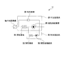
以下、図面を参照しながら、本発明の好ましい実施形態を詳細に説明する。図1は、本発明の第1実施形態による振動抑制装置1をモデル化して示している。同図に示すように、振動抑制装置1は、第1粘性要素、第1慣性接続要素及び軸力制限機構を備えている。
Hereinafter, preferred embodiments of the present invention will be described in detail with reference to the drawings. FIG. 1 shows a model of a
上記の第1粘性要素及び第1慣性接続要素は、構造物の振動を抑制するために粘性減衰効果及び回転慣性効果をそれぞれ発揮するものであり、軸力制限機構は、振動抑制装置1の軸力(反力)を制限するためのものである。
The first viscous element and the first inertia connecting element each exhibit a viscous damping effect and a rotational inertia effect in order to suppress the vibration of the structure, and the axial force limiting mechanism is a shaft of the
図2は、上記の振動抑制装置1を具現化して示している。振動抑制装置1は、円筒状のシリンダ2と、シリンダ2に収容されたロッド3及び第1ピストン4を備えている。
FIG. 2 illustrates the
シリンダ2は、軸線方向に互いに対向する一対の側壁2a、2aと、両者2a、2aの間に一体に設けられた周壁2bで構成されている。これらの側壁2a,2a及び周壁2bによって画成された油室は、第1ピストン4によって第1油室2c及び第2油室2dに分割されており、両油室2c、2dには、作動油HFが充填されている。これらの第1及び第2油室2c、2dは、第1ピストン4に対して軸線方向の一方の側及び他方の側に、それぞれ配置されている。この作動油HFが、前述した第1粘性要素に相当する。
The
また、各側壁2aの径方向の中央には、軸線方向に貫通するロッド案内孔2eが形成されており、ロッド案内孔2eには、シール5が設けられている。さらに、軸線方向の一方の側(図2の左側)の側壁2aには、軸線方向に突出する凸部2fが一体に設けられており、凸部2fの内側には、収容部2gが画成されている。さらに、凸部2fには、自在継手を介して、第1取付具FL1が設けられている。
Further, a
前記ロッド3は、上記のロッド案内孔2e、2eに挿入され、軸線方向に延びており、シリンダ2に対して軸線方向に移動自在である。また、ロッド3は、その一端部が上記の収容部2gに収容されており、一端部以外の大部分がシリンダ2に収容されている。通常、ロッド3は、図2に示す中立位置に位置しており、この状態では、上記の第1及び第2油室2c、2dの容積は互いに等しい。また、ロッド3の他端部には、自在継手を介して、第2取付具FL2が設けられている。
The
前記第1ピストン4は、円柱状に形成されており、ロッド3に一体に固定されている。第1ピストン4の周面には、シール6が設けられている。また、第1ピストン4の径方向の外端部には、軸線方向に貫通する複数の孔が形成されており(2つのみ図示)、これらの孔には、第1リリーフ弁7及び第2リリーフ弁8が設けられている。第1リリーフ弁7は、弁体7aと、これを閉弁側に付勢するばね7bで構成されており、第1油室2c内の作動油HFの圧力が所定値に達したときに開弁し、それにより第1及び第2油室2c、2dが互いに連通される。
The
第2リリーフ弁8は、第1リリーフ弁7と同様、弁体8aと、これを閉弁側に付勢するばね8bで構成されており、第2油室2d内の作動油HFの圧力が所定値に達したときに開弁し、それにより第1及び第2油室2c、2dが互いに連通される。これらの第1及び第2リリーフ弁7、8が、前述した軸力制限機構(図1参照)に相当する。
Similar to the
また、振動抑制装置1は、バイパス管11、ねじ軸15、第2ピストン16及び第1回転マス21、21を備えている。この第1回転マス21、21が、前述した第1慣性接続要素(図1参照)に相当する。バイパス管11は、シリンダ2に、第1ピストン4をバイパスするように接続されており、第1及び第2油室2c、2dに連通している。
The
また、バイパス管11は、シリンダ2を中央として互いに対称に設けられた第1管路12及び第2管路13と、シリンダ2と平行に延びる第3管路14を一体に有している。これらの第1〜第3管路12〜14の断面(軸線方向に直交する面)は円形である。バイパス管11の断面積(軸線方向に直交する面の面積)は、シリンダ2の断面積(軸線方向に直交する面の面積)よりも小さな値に設定されている。
The
第1管路12の一端部は、シリンダ2の一方の側壁2aの径方向の外端部に接続されている。第1管路12は、この側壁2aから軸線方向の一方の側に延びるとともに、直角に屈曲して径方向の外方に延びている。また、第1管路12の他端部は、第3管路14の軸線方向の一端部に接続されている。第2管路13の一端部は、シリンダ2の他方の側壁2aの径方向の外端部に接続されている。第2管路13は、この側壁2aから軸線方向の他方の側に延びるとともに、直角に屈曲して径方向の外方に延びている。また、第2管路13の他端部は、第3管路14の軸線方向の他端部に接続されている。
One end of the
さらに、第3管路14の周壁14aの内面には、一対のレール14b、14bが一体に設けられている。便宜上、図2や後述する他の図面では、レール14b、14bの断面を示すハッチングを省略している。図3に示すように、両者14b、14bは、第3管路14の径方向に若干、突出するとともに、径方向において互いに対向するように配置されている。各レール14bは、第3管路14の第1管路12との接続部と第2管路13との接続部の間の全体にわたって、軸線方向に延びている。
Further, a pair of
また、第3管路14の軸線方向の一端部及び他端部の壁部14c、14cには、軸線方向に貫通する支持孔14d、14dが形成されている。また、各壁部14cの内面には、軸受け22が取り付けられており、各支持孔14dには、シール23が設けられている。これらの支持孔14d、スラスト軸受け22及びシール23は、第3管路14に同軸状に配置されている。
In addition,
ねじ軸15は、上記の支持孔14b、14bに挿入され、スラスト軸受け22、22に回転自在に支持されるとともに、第3管路14に部分的に収容されており、第3管路14の軸線方向に延びている。ねじ軸15の軸線方向の一方の側の部分及び他方の側の部分には、フランジ15a、15aが一体に設けられており、これらのフランジ15a、15aは、軸線方向の内側から、スラスト軸受け22、22にそれぞれ接触している。以上の構成により、ねじ軸15は、第3管路14に対して回転可能であり、かつ軸線方向に移動不能である。
The
前記第2ピストン16は、円筒状のナット17、第1受圧部18及び第2受圧部19で構成されており、第3管路14に収容されている。図4に示すように、ナット17は、ボール17aを介して、ねじ軸15に螺合しており、ねじ軸15に対して回転可能である。このように、ねじ軸15、ナット17及びボール17aは、ボールねじを構成している。ねじ軸15及びナット17のリード角は、比較的小さな値に設定されている。
The
第1及び第2受圧部18、19は、ドーナツ板状に形成され、ナット17よりも大きな外径を有しており、ナット17の軸線方向の両端部に同軸状に一体に固定されている。図3及び図4に示すように、第1受圧部18には、その外周部に一対の凹部18a、18aが形成されており、その外周面にシール24が取り付けられている。また、第1受圧部18の径方向の中央には、軸線方向に貫通する案内孔18bが形成されており、案内孔18bには、シール25が取り付けられている。
The first and second
第2受圧部19には、第1受圧部18と同様、その外周部に一対の凹部19a、19aが形成されており、その外周面にシール24が取り付けられている。また、第2受圧部19の径方向の中央には、案内孔19bが形成されており、案内孔19bには、シール25が取り付けられている。
As with the first
第1及び第2受圧部18、19は、第3管路14の内周面に、シール24を介して嵌合するとともに、それらの凹部18a、18a及び19a、19aが、第3管路14のレール14b及び14bに、シール24を介して係合している。また、第1及び第2受圧部18、19の案内孔18b及び19bには、ねじ軸15が、シール25を介して回転可能に嵌合している。
The first and second
以上の構成により、第2ピストン16は、ねじ軸15に対して回転可能であり、また、ねじ軸15に沿って第3管路14内を摺動可能で、かつ第3管路14に対して回転不能である。
With the above configuration, the
また、図2に示すように、ねじ軸15の一端部及び他端部は、第3管路14の壁部14c、14cよりも外側に突出する突出部15b、15bになっており、各突出部15bに、前記第1回転マス21が同軸状に固定されている。第1回転マス21は、比重の比較的大きい材料(例えば鉄)を用いて、ドーナツ板状に形成されている。
Moreover, as shown in FIG. 2, the one end part and other end part of the
図5は、振動抑制装置1を構造物(例えば高層の建築物)B1に設置した場合の例を示している。同図に示すように、第1取付具FL1が、弾性を有する第1支持部材SU1を介して下側の梁BD1に連結されるとともに、第2取付具FL2が、弾性を有する第2支持部材SU2を介して上側の梁BU1に連結されており、それにより、振動抑制装置1は、これらの梁BU1、BD1に対して、平行に取り付けられている。
FIG. 5 shows an example in which the
地震などによる振動により構造物B1が往復動すると、上下の梁BU1、BD1の間の変位(以下「構造物B1の変位」という)が、シリンダ2及びロッド3に伝達され、それに伴い、ロッド3が、シリンダ2に対して軸線方向に往復動する。この場合、ロッド3がシリンダ2に対して中立位置から軸線方向の一方の側(図2の左側)に移動すると、ロッド3と一体の第1ピストン4がシリンダ2内を一方の側に摺動し、それに伴い、第1油室2c内の作動油HFが圧縮されるとともに、第2油室2dが拡大する。
When the structure B1 reciprocates due to vibration caused by an earthquake or the like, displacement between the upper and lower beams BU1 and BD1 (hereinafter referred to as “displacement of the structure B1”) is transmitted to the
これにより、第1油室2c内の作動油HFの一部が、バイパス管11の第1管路12を介して第3管路14に流入するとともに、第2ピストン16の第1受圧部18を押圧することによって、第2ピストン16が、ねじ軸15に沿って、第3管路14内を軸線方向の他方の側に摺動する。それに伴い、第2ピストン16のナット17にボール17aを介して螺合するねじ軸15が、第3管路14に対して回転し、ねじ軸15と一体の第1回転マス21、21も回転する。
As a result, a part of the hydraulic oil HF in the
上記とは逆に、ロッド3がシリンダ2に対して中立位置から軸線方向の他方の側(図2の右側)に移動すると、第1ピストン4がシリンダ2内を他方の側に摺動し、それに伴い、第2油室2d内の作動油HFが圧縮されるとともに、第1油室2cが拡大する。これにより、第2油室2d内の作動油HFの一部が、バイパス管11の第2管路13を介して第3管路14に流入するとともに、第2ピストン16の第2受圧部19を押圧することによって、第2ピストン16が、ねじ軸15に沿って、第3管路14内を軸線方向の一方の側に摺動する。それに伴い、ねじ軸15が第3管路14に対して回転し、ねじ軸15と一体の第1回転マス21、21も回転する。
Contrary to the above, when the
なお、バイパス通路11及びねじ軸15の長さは、第1ピストン4の移動に伴う第2ピストン16の最大の移動量よりも大きな値に設定されている。
The lengths of the
以上のように、第1実施形態によれば、振動による構造物B1の変位は、ロッド3及び第1ピストン4を介して作動油HFに伝達され、さらに第1又は第2受圧部18、19、ナット17、ボール17a及びねじ軸15を介して第1回転マス21、21に伝達されることにより、第1回転マス21、21が回転する。したがって、作動油HFの粘性減衰効果と第1回転マス21、21の回転慣性効果によって、構造物B1の振動を抑制することができる。
As described above, according to the first embodiment, the displacement of the structure B <b> 1 due to vibration is transmitted to the hydraulic oil HF via the
この場合、前述した従来の場合と異なり、羽根車ではなく、ねじ軸15、ナット17及びボール17aから成るボールねじと第2ピストン16を用いて、作動油HFの流動が回転運動に変換されるとともに、ねじ軸15及びナット17のリード角が比較的小さな値に設定されている。したがって、作動油HFの流量が比較的小さいことで第2ピストン16の移動量が比較的小さい場合でも、ねじ軸15及び第1回転マス21、21を十分に回転させることができる。以上のように、構造物B1の変位を、作動油HFを介して第1回転マス21、21の回転運動に効率良く変換でき、それにより、構造物B1の振動を適切に抑制することができる。
In this case, unlike the above-described conventional case, the flow of the hydraulic oil HF is converted into a rotational motion by using a ball screw including the
また、振動抑制装置1は、弾性を有する第1及び第2支持部材SU1、SU2を介して構造物B1に連結されているので、これらの第1及び第2支持部材SU1、SU2並びに第1回転マス21及び作動油HFによって、付加振動系を構成することができる。第1実施形態では、バイパス管11の断面積、ねじ軸15及びナット17のリード角、作動油HFの粘性減衰係数、第1回転マス21の質量、並びに第1及び第2支持部材SU1、SU2のばね定数は、この付加振動系の固有振動数が例えば構造物B1の一次の固有振動数に同調(共振)するように、設定されている。
Moreover, since the
したがって、付加振動系の固有振動数を構造物B1の一次の固有振動数に適切に同調させることができ、ひいては、構造物B1の一次モードによる振動を適切に抑制することができる。なお、同調させる構造物B1の固有振動数は、一次の固有振動数に限らず、他の任意の固有振動数でもよい。 Therefore, the natural frequency of the additional vibration system can be appropriately tuned to the primary natural frequency of the structure B1, and hence vibration due to the primary mode of the structure B1 can be appropriately suppressed. The natural frequency of the structure B1 to be tuned is not limited to the primary natural frequency, and may be any other natural frequency.
また、上述した付加振動系の固有振動数の調整において、具体的には、バイパス管11の断面積を変更することによって、作動油HFの流動に対するナット17の回転運動への変換効率すなわち第1回転マス21、21の回転慣性効果と、作動油HFの粘性減衰効果を調整することができる。さらに、ねじ軸15及びナット17のリード角を変更することによって、作動油HFの流動に対するナット17の回転運動への変換効率すなわち第1回転マス21、21の回転慣性効果を調整することができるとともに、作動油HFの粘性減衰係数を変更することによって、作動油HFの粘性減衰効果を調整することができる。また、第1回転マス21、21の質量を変更することによって、第1回転マス21、21の回転慣性効果を調整することができる。
Further, in the adjustment of the natural frequency of the additional vibration system described above, specifically, by changing the cross-sectional area of the
さらに、バイパス管11の断面積がシリンダ2の断面積よりも小さな値に設定されているので、シリンダ2内の第1ピストン4の移動量に対して、バイパス管11内の第2ピストン16の移動量を増大させ、第1回転マス21、21の回転量を増大させることができる。したがって、第1回転マス21、21の回転慣性力をより適切に得ることができ、ひいては、構造物B1の振動をより適切に抑制することができる。
Further, since the cross-sectional area of the
また、第1回転マス21、21がバイパス管11の外部に配置されているので、第1回転マス21、21の質量の調整を容易に行うことができる。
Moreover, since the
さらに、第1又は第2油室2c、2d内の作動油HFの圧力が所定値に達したときに、すなわち、作動油HFの粘性減衰力及び第1回転マス21、21の回転慣性力から成る振動抑制装置1の反力(軸力)が比較的大きくなったときに、両油室2c、2dが第1及び第2リリーフ弁7、8によって連通される。これにより、第1ピストン4がシリンダ2内を摺動しても、シリンダ2内で作動油HFの圧縮及び作動油HFの流動がほとんど行われなくなるので、作動油HFの粘性減衰力及び第1回転マス21、21の回転慣性力が頭打ちになり、したがって、その過大化を防止することができる。
Further, when the pressure of the hydraulic oil HF in the first or
なお、第1実施形態では、第1回転マス21、21を、ねじ軸15に固定しているが、ねじ軸15に回転自在に設けるとともに、ねじ軸15に弾性体又は粘弾性体を介して連結してもよい。この場合、これらの弾性体又は粘弾性体及び第1回転マス21、21によって付加振動系が構成されるため、前述した第1及び第2支持部材SU1、SU2が不要になるので、その分、振動抑制装置1全体を小型化することができる。また、第1実施形態では、バイパス管11、ねじ軸15、第2ピストン16及び第1回転マス21、21を1組、設けているが、2組以上を並列に設けてもよい。
In the first embodiment, the first
次に、図6及び図7を参照しながら、本発明の第2実施形態による振動抑制装置1Aについて説明する。図6は、振動抑制装置1Aをモデル化して示しており、この図6と前述した図1との比較から明らかなように、振動抑制装置1Aは、第1実施形態と比較して、第1弾性要素が第1慣性接続要素に直列に接続されていることのみが、異なっている。また、これらの第1弾性要素、第1慣性接続要素及び第1粘性要素によって、第1付加振動系が構成されている。
Next, a
また、図7は、振動抑制装置1Aを具現化して示している。同図に示すように、振動抑制装置1Aは、第1実施形態と比較して、上記の第1弾性要素に相当する第1ばね34及び第2ばね35が第2ピストン31に設けられている点が、主に異なっている。図7において、第1実施形態と同じ構成要素については、同じ符号を付している。以下、第1実施形態と異なる点を中心に説明する。
FIG. 7 shows the
第2ピストン31は、第1実施形態の第2ピストン16と同様、ナット17、第1受圧部18及び第2受圧部19を有している。第1及び第2受圧部18、19は、ナット17に一体に固定されておらず、ナット17の軸線方向の両端部には、第1フランジ32及び第2フランジ33が同軸状に一体に固定されている。
The
これらの第1及び第2フランジ32、33はそれぞれ、基本的には、第1及び第2受圧部18、19と同様に構成されており、第3管路14のレール14bに係合する凹部、及び、ねじ軸15が挿入される案内孔(いずれも図示せず)が設けられている。なお、第1及び第2フランジ32、33には、第1及び第2受圧部18、19と異なり、シール24及び25が設けられていない。
These first and
第1受圧部18は、ナット17に対して軸線方向の一方の側に設けられており、第1ばね34を介して第1フランジ32に取り付けられている。第2受圧部19は、ナット17に対して軸線方向の他方の側に設けられており、第2ばね35を介して第2フランジ33に取り付けられている。第1及び第2ばね34、35はいずれも、圧縮コイルばねであり、両者34、35のばね定数は互いに同じ値に設定されており、その詳細については後述する。
The first
以上の構成により、第1及び第2受圧部18、19、第1及び第2ばね34、35、第1及び第2フランジ32、33並びにナット17を有する第2ピストン31は、ねじ軸15に対して回転可能であり、また、ねじ軸15に沿って第3管路14内を摺動可能で、かつ第3管路14に対して回転不能である。
With the above configuration, the
図8は、振動抑制装置1Aを構造物(例えば高層の建築物)B2に設置した場合の例を示している。同図に示すように、第1取付具FL1が直接、構造物B2の左側の柱PLと上側の梁BU2との接続部分に連結されるとともに、第2取付具FL2が直接、構造物B2の右側の柱PRと下側の梁BD2との接続部分に連結されており、それにより、振動抑制装置1Aは、これらの柱PL、PR及び梁BU2、BD2に対して、斜めに取り付けられている。
FIG. 8 shows an example in which the
地震などによる振動により構造物B2が往復動すると、左右の柱PL、PR及び上下の梁BU、BDの間の変位(以下「構造物B2の変位」という)が、シリンダ2及びロッド3に伝達され、それに伴い、ロッド3が、シリンダ2に対して軸線方向に往復動する。この場合、ロッド3がシリンダ2に対して中立位置から軸線方向の一方の側(図7の左側)に移動すると、ロッド3と一体の第1ピストン4がシリンダ2内を一方の側に摺動し、それに伴い、第1油室2c内の作動油HFが圧縮されるとともに、第2油室2dが拡大する。
When the structure B2 reciprocates due to vibration caused by an earthquake or the like, displacement between the left and right columns PL, PR and the upper and lower beams BU, BD (hereinafter referred to as “displacement of the structure B2”) is transmitted to the
これにより、第1油室2c内の作動油HFの一部が、バイパス管11の第1管路12を介して第3管路14に流入するとともに、第2ピストン31の第1受圧部18を押圧する。作動油HFの押圧力は、第1受圧部18、第1ばね34及び第1フランジ32を介して、ナット17に伝達され、それにより、ナット17を含む第2ピストン31全体が、ねじ軸15に沿って、第3管路14内を軸線方向の他方の側に摺動する。それに伴い、ねじ軸15が第3管路14に対して回転し、ねじ軸15と一体の第1回転マス21、21も回転する。
As a result, a part of the hydraulic oil HF in the
上記とは逆に、ロッド3がシリンダ2に対して中立位置から軸線方向の他方の側(図7の右側)に移動すると、第1ピストン4がシリンダ2内を他方の側に摺動し、それに伴い、第2油室2d内の作動油HFが圧縮されるとともに、第1油室2cが拡大する。これにより、第2油室2d内の作動油HFの一部が、バイパス管11の第2管路13を介して第3管路14に流入するとともに、第2ピストン31の第2受圧部19を押圧する。作動油HFの押圧力は、第2受圧部19、第2ばね35及び第2フランジ33を介して、ナット17に伝達され、それにより、ナット17を含む第2ピストン31全体が、ねじ軸15に沿って、第3管路14内を軸線方向の一方の側に摺動する。それに伴い、ねじ軸15が第3管路14に対して回転し、ねじ軸15と一体の第1回転マス21、21も回転する。
Contrary to the above, when the
以上のように、第2実施形態によれば、振動による構造物B2の変位は、第1ピストン4が一方の側に摺動したときには作動油HF、第1受圧部18及び第1ばね34を介して、第1ピストン4が他方の側に摺動したときには作動油HF、第2受圧部19及び第2ばね35を介して、ナット17に伝達され、さらにねじ軸15を介して第1回転マス21、21に伝達される結果、第1回転マス21、21が回転する。このように、振動による構造物B2の往復動に対して、作動油HF、第1又は第2ばね34、35及び第1回転マス21、21から成る第1付加振動系が構成される。
As described above, according to the second embodiment, the displacement of the structure B2 due to the vibration causes the hydraulic oil HF, the first
第2実施形態では、バイパス管11の断面積、ねじ軸15及びナット17のリード角、作動油HFの粘性減衰係数、第1回転マス21、21の質量、並びに第1及び第2ばね34、35のばね定数は、この第1付加振動系の固有振動数が例えば構造物B2の一次の固有振動数に同調(共振)するように、設定されている。
In the second embodiment, the cross-sectional area of the
したがって、第1付加振動系の固有振動数を構造物B2の一次の固有振動数に適切に同調させることができ、ひいては、構造物B2の一次モードによる振動を適切に抑制することができる。なお、同調させる構造物B2の固有振動数は、一次の固有振動数に限らず、他の任意の固有振動数でもよい。 Therefore, the natural frequency of the first additional vibration system can be appropriately tuned to the primary natural frequency of the structure B2, and hence vibration due to the primary mode of the structure B2 can be appropriately suppressed. The natural frequency of the structure B2 to be tuned is not limited to the primary natural frequency, and may be any other natural frequency.
また、上述した第1付加振動系の固有振動数の調整において、具体的には、バイパス管11の断面積を変更することによって、作動油HFの流動に対するナット17の回転運動への変換効率すなわち第1回転マス21、21の回転慣性効果と、作動油HFの粘性減衰効果を調整することができる。さらに、ねじ軸15及びナット17のリード角を変更することによって、作動油HFの流動に対するナット17の回転運動への変換効率すなわち第1回転マス21、21の回転慣性効果を調整することができるとともに、作動油HFの粘性減衰係数を変更することによって、作動油HFの粘性減衰効果を調整することができる。また、第1回転マス21、21の質量を変更することによって、第1回転マス21、21の回転慣性効果を調整することができる。
In the adjustment of the natural frequency of the first additional vibration system described above, specifically, by changing the cross-sectional area of the
さらに、バイパス管11の断面積がシリンダ2の断面積よりも小さな値に設定されているので、第2ピストン16に作用する作動油HFの押圧力を、第1ピストン4に作用する作動油HFの押圧力よりも小さくすることができるので、第1及び第2ばね34、35として、ばね定数の小さいコンパクトなものを採用することができる。
Furthermore, since the cross-sectional area of the
また、第1実施形態と異なり、第3管路14内に設けられた第1及び第2ばね34、35を用いて第1付加振動系を構成でき、それにより第1及び第2支持部材SU1、SU2が不要であるので、その分、振動抑制装置1A全体を小型化することができる。その他、第1実施形態による効果を同様に得ることができる。
Further, unlike the first embodiment, the first additional vibration system can be configured by using the first and
次に、図9を参照しながら、本発明の第3実施形態による振動抑制装置1Bについて説明する。この振動抑制装置1Bは、第2実施形態と比較して、第1及び第2ばね41、42のばね定数が互いに異なる値に設定されていることのみが、異なっている。図9において、第2実施形態と同じ構成要素については、同じ符号を付している。以下、第2実施形態と異なる点を中心に説明する。
Next, a
第2実施形態で述べた振動抑制装置1Aの動作から明らかなように、第3実施形態による振動抑制装置1Bでは、振動による構造物B2の変位は、第1ピストン4が一方の側に摺動したときには作動油HF、第1受圧部18及び第1ばね41を介して、第1ピストン4が他方の側に摺動したときには作動油HF、第2受圧部19及び第2ばね42を介して、ナット17に伝達され、さらにねじ軸15を介して第1回転マス21、21に伝達される結果、第1回転マス21、21が回転する。このように、振動による構造物B2の往復動に対して、作動油HF、第1ばね41及び第1回転マス21、21から成る第1付加振動系と、作動油HF、第2ばね42及び第1回転マス21、21から成る第2付加振動系が構成される。
As is apparent from the operation of the
第3実施形態では、第1ばね41のばね定数、バイパス管11の断面積、ねじ軸15及びナット17のリード角、作動油HFの粘性減衰係数、並びに第1回転マス21、21の質量は、この第1付加振動系の固有振動数が例えば構造物B2の一次の固有振動数に同調(共振)するように、設定されている。また、第2ばね42のばね定数、バイパス管11の断面積、ねじ軸15及びナット17のリード角、作動油HFの粘性減衰係数、並びに第1回転マス21、21の質量は、上記の第2付加振動系の固有振動数が例えば構造物B2の二次の固有振動数に同調(共振)するように、設定されている。
In the third embodiment, the spring constant of the
これにより、第1及び第2付加振動系の固有振動数を、構造物B2の一次及び二次の固有振動数にそれぞれ多重同調させることができる。したがって、作動油HFや、第1回転マス21、21、第1ばね41、第2ばね42などから成る一基の振動抑制装置1Bによって、一次及び二次の振動モードの構造物B2の振動を適切に抑制でき、ひいては、装置のさらなる小型化を図ることができる。なお、同調させる構造物B2の固有振動数は、一次及び二次の固有振動数に限らず、他の任意の固有振動数でもよい。その他、第1及び第2実施形態による効果を同様に得ることができる。
As a result, the natural frequencies of the first and second additional vibration systems can be multiple-tuned to the primary and secondary natural frequencies of the structure B2, respectively. Therefore, the vibration of the structure B2 in the primary and secondary vibration modes is caused by the
なお、第2及び第3実施形態では、バイパス管11、ねじ軸15、第2ピストン16、第1回転マス21、21、第1及び第2ばね34、35(41、42)を1組、設けているが、2組以上を並列に設けてもよい。この場合、第1回転マスの質量などを、それにより構成される複数の付加振動系の固有振動数が構造物B2の同じ1つの所望の固有振動数に同調するように、設定してもよく、あるいは、構造物B2の互いに異なる複数の所望の固有振動数に同調するように、設定してもよい。
In the second and third embodiments, the
次に、図10及び図11を参照しながら、本発明の第4実施形態による振動抑制装置1Cについて説明する。図10は、振動抑制装置1Cをモデル化して示しており、この図10と前述した図6との比較から明らかなように、振動抑制装置1Cは、第2実施形態と比較して、第2弾性要素及び第2慣性接続要素が第1慣性接続要素に並列に接続されていることのみが、異なっている。また、これらの第2弾性要素及び第2慣性接続要素によって、第2付加振動系が構成されている。
Next, a
図11は、振動抑制装置1Cを具現化して示している。同図に示すように、振動抑制装置1Cは、第2実施形態と比較して、上記の第2弾性要素に相当するばね51と、第2慣性接続要素に相当する第2回転マス52、52を備える点のみが、異なっている。図11において、第1及び第2実施形態と同じ構成要素については、同じ符号を付している。以下、第1及び第2実施形態と異なる点を中心に説明する。
FIG. 11 illustrates the
第2回転マス52、52は、比較的比重の大きい材料(例えば鉄)を用いて、ドーナツ板状に形成されており、ねじ軸15の突出部15b、15bに、ラジアル軸受け53、53を介して、同軸状に回転自在に支持されている。また、各第2回転マス52は、ばね51を介して、第1回転マス21に取り付けられており、第1回転マス21に対して回転可能である。ばね51は、ねじりコイルばねである。
The second
以上の構成の振動抑制装置1Cは、例えば第2実施形態と同様にして、構造物B2に取り付けられる。地震などによる振動により構造物B2が往復動すると、第2実施形態と同様、構造物B2の変位が、シリンダ2及びロッド3に伝達され、さらに、作動油HFを介して第2ピストン31に伝達される結果、ねじ軸15が第1回転マス21、21とともに回転する。また、第1回転マス21、21の回転に伴って、第2回転マス52、52が回転する。
The
以上により、第4実施形態によれば、作動油HFの粘性減衰効果及び第1回転マス21、21の回転慣性効果に加え、第2回転マス52、52の回転慣性効果によって、構造物B2の振動をより適切に抑制することができる。
As described above, according to the fourth embodiment, in addition to the viscous damping effect of the hydraulic oil HF and the rotational inertia effect of the first
また、第2回転マス52、52が、ばね51を介して第1回転マス21、21に取り付けられているので、第2実施形態で述べた第1付加振動系に加え、ばね51及び第2回転マス52、52から成る第2付加振動系をさらに構成することができる。この場合、図10から明らかなように、第1及び第2付加振動系の組合わせにより構成された付加振動系の固有振動数として、2つの組合わせ固有振動数がそれぞれ別個に存在する。
Since the second
第4実施形態では、バイパス管11の断面積、ねじ軸15及びナット17のリード角、作動油HFの粘性減衰係数、第1回転マス21、21の質量、第1及び第2ばね34、35のばね定数、第2回転マス52、52の質量、並びにばね51のばね定数は、上記の2つの組合わせ固有振動数が例えば構造物B2の一次及び二次の固有振動数にそれぞれ同調(共振)するように、設定されている。
In the fourth embodiment, the cross-sectional area of the
したがって、第1及び第2付加振動系の2つの組合わせ固有振動数を構造物B2の一次及び二次の固有振動数にそれぞれ適切に多重同調させることができ、ひいては、構造物B2の一次及び二次モードによる振動を適切に抑制することができる。なお、同調させる構造物B2の固有振動数は、一次及び二次の固有振動数に限らず、他の任意の互いに異なる2つの固有振動数でもよい。あるいは、2つの組合わせ固有振動数を、構造物B2の同じ1つの固有振動数に同調させてもよい。 Therefore, the two combined natural frequencies of the first and second additional vibration systems can be appropriately multiple-tuned to the primary and secondary natural frequencies of the structure B2, respectively. Vibration due to the secondary mode can be appropriately suppressed. The natural frequency of the structure B2 to be tuned is not limited to the primary and secondary natural frequencies, but may be any other two different natural frequencies. Alternatively, the two combined natural frequencies may be tuned to the same single natural frequency of the structure B2.
また、上述した第1及び第2付加振動系の固有振動数の調整において、具体的には、バイパス管11の断面積を変更することによって、作動油HFの流動に対するナット17の回転運動への変換効率すなわち第1及び第2回転マス21、21、52、52の回転慣性効果と、作動油HFの粘性減衰効果を調整することができる。
Further, in the adjustment of the natural frequencies of the first and second additional vibration systems described above, specifically, by changing the cross-sectional area of the
さらに、ねじ軸15及びナット17のリード角を変更することによって、作動油HFの流動に対するナット17の回転運動への変換効率すなわち第1及び第2回転マス21、21、52、52の回転慣性効果を調整することができるとともに、作動油HFの粘性減衰係数を変更することによって、作動油HFの粘性減衰効果を調整することができる。また、第1及び第2回転マス21、21、52、52の質量を変更することによって、第1及び第2回転マス21、21、52、52の回転慣性効果をそれぞれ調整することができる。
Further, by changing the lead angle of the
また、第2回転マス52、52が、第1回転マス21、21と同様、バイパス管11の外部に配置されているので、第2回転マス52、52の質量の設定を容易に行うことができる。その他、第1及び第2実施形態による効果を同様に得ることができる。
Moreover, since the
なお、第4実施形態では、ばね51は、ねじりコイルばねであるが、他の弾性体、例えばゴムでもよい。また、第4実施形態では、第2回転マス52を第1回転マス21に、ばね51を介して取り付けているが、粘性を有する粘性体をさらに介して取り付けてもよい。あるいは、ばね51に代えて、弾性及び粘性の双方を有する粘弾性体、例えば粘弾性ゴムを介して取り付けてもよい。
In the fourth embodiment, the
さらに、第4実施形態では、第2実施形態で述べたようにばね定数が互いに同じ値に設定された第1及び第2ばね34、35を用いているが、両者34、35に代えて、第3実施形態で述べたばね定数が互いに異なる値に設定された第1及び第2ばね41、42を用いてもよい。この場合、第1及び第2付加振動系の組合わせにより構成された付加振動系の固有振動数として、4つの組合わせ固有振動数がそれぞれ別個に存在する。
Furthermore, in the fourth embodiment, as described in the second embodiment, the first and
また、バイパス管11の断面積、ねじ軸15及びナット17のリード角、作動油HFの粘性減衰係数、第1回転マス21、21の質量、第1及び第2ばね41、42のばね定数、第2回転マス52、52の質量、並びにばね51のばね定数は、例えば、上記の4つの組合わせ固有振動数が構造物B2の一次〜四次の固有振動数にそれぞれ同調(共振)するように、設定される。なお、同調させる構造物B2の固有振動数は、一次〜四次の固有振動数に限らず、他の任意の固有振動数でもよい。
Further, the cross-sectional area of the
さらに、第4実施形態では、バイパス管11、ねじ軸15、第2ピストン16、第1回転マス21、21、第2回転マス52、52、第1及び第2ばね34、35を1組、設けているが、2組以上を並列に設けてもよい。この場合、第1回転マスの質量などを、それにより構成される複数の付加振動系の固有振動数が構造物B2の同じ1つの所望の固有振動数に同調するように、設定してもよく、あるいは、構造物B2の互いに異なる複数の所望の固有振動数に同調するように、設定してもよい。
Further, in the fourth embodiment, the
また、第2〜第4実施形態では、第1及び第2ばね34、41、35、42は、圧縮コイルばねであるが、他の弾性体、例えばゴムでもよい。
In the second to fourth embodiments, the first and
なお、本発明は、説明した第1〜第4実施形態(以下、総称して「実施形態」という)に限定されることなく、種々の態様で実施することができる。例えば、実施形態では、本発明の作動流体として、作動油HFを用いているが、粘性を有する他の適当な流体を用いてもよい。また、実施形態では、第2ピストン16、31をバイパス管11(第3管路14)に対して回転不能にするために、レール14bを第1及び第2受圧部18、19の凹部18a、19a(フランジ32、33の凹部)に係合させているが、これらのレール14b、凹部18a及び19aを設けずに、バイパス管及び第2ピストンの断面を矩形に形成するとともに、バイパス管に第2ピストンを摺動自在に嵌合させてもよい。
The present invention is not limited to the described first to fourth embodiments (hereinafter collectively referred to as “embodiments”), and can be implemented in various modes. For example, in the embodiment, the working oil HF is used as the working fluid of the present invention, but other suitable fluid having viscosity may be used. Further, in the embodiment, in order to make the
さらに、実施形態では、第1及び第2回転マス21、21、52、52を、バイパス管11の第3管路14の外部に設けているが、その内部に設けてもよい。また、実施形態では、第1及び第2リリーフ弁7、8を、第1ピストン4に設けているが、シリンダ2に、第1ピストン4をバイパスして第1及び第2油室2c、2dを互いに連通するバイパス管をさらに設けるとともに、このバイパス管に、第1及び第2リリーフ弁を設けてもよい。さらに、第1及び第2リリーフ弁7、8の一方又は双方を省略してもよい。
Furthermore, in the embodiment, the first and second
また、実施形態では、振動抑制装置1、1A〜1Cを、構造物B1、B2の層間に設置し、いわゆる制振装置として用いているが、構造物B1、B2とこれを支持する支持体との間に設置し、いわゆる免震装置として用いてもよい。さらに、実施形態は、本発明を高層の建築物である構造物B1、B2に適用した例であるが、本発明による振動抑制装置は、他の適当な構造物、例えば橋梁や鉄塔などにも適用可能である。その他、本発明の趣旨の範囲内で、細部の構成を適宜、変更することが可能である。
In the embodiment, the
1 振動抑制装置
2 シリンダ
2c 第1油室(第1圧力室)
2d 第2油室(第2圧力室)
3 ロッド
4 第1ピストン
7 第1リリーフ弁(リリーフ弁)
8 第2リリーフ弁(リリーフ弁)
HF 作動油(作動流体)
11 バイパス管(バイパス通路)
15 ねじ軸
16 第2ピストン
17 ナット
17a ボール
18 第1受圧部
19 第2受圧部
21 第1回転マス(回転マス)
B1 構造物
BD1 下側の梁(構造物を含む系内の2つの部位の一方)
BU1 上側の梁(構造物を含む系内の2つの部位の他方)
1A 振動抑制装置
31 第2ピストン
34 第1ばね(第1弾性体)
35 第2ばね(第2弾性体)
B2 構造物
PL 左側の柱(構造物を含む系内の2つの部位の一方)
BU2 上側の梁(構造物を含む系内の2つの部位の一方)
PR 右側の柱(構造物を含む系内の2つの部位の他方)
BD2 下側の梁(構造物を含む系内の2つの部位の他方)
1B 振動抑制装置
41 第1ばね(第1弾性体)
42 第2ばね(第2弾性体)
1C 振動抑制装置
51 ばね(弾性体)
52 第2回転マス(回転マス)
DESCRIPTION OF
2d Second oil chamber (second pressure chamber)
3
8 Second relief valve (Relief valve)
HF hydraulic oil (working fluid)
11 Bypass pipe (bypass passage)
15
B1 Structure BD1 Lower beam (one of the two parts in the system including the structure)
BU1 Upper beam (the other of the two parts in the system including the structure)
1A
35 Second spring (second elastic body)
B2 Structure PL Left column (one of the two parts in the system including the structure)
BU2 Upper beam (one of the two parts in the system including the structure)
PR Right column (the other of the two parts in the system including the structure)
BD2 Lower beam (the other of the two parts in the system including the structure)
1B
42 Second spring (second elastic body)
1C
52 Second rotating mass (Rotating mass)
Claims (7)
前記2つの部位の一方に連結されるとともに、作動流体が充填されたシリンダと、
前記2つの部位の他方に連結され、前記シリンダに部分的に収容されるとともに、当該シリンダに対して軸線方向に移動可能なロッドと、
当該ロッドに一体に固定され、前記ロッドの移動に伴って前記シリンダ内を摺動する第1ピストンと、
当該第1ピストンをバイパスするように前記シリンダに接続されたバイパス通路と、
当該バイパス通路内に回転可能に設けられ、前記バイパス通路の軸線方向に延びるねじ軸と、
当該ねじ軸にボールを介して螺合するナットを有するとともに、前記ねじ軸に沿って前記バイパス通路内を摺動可能で、かつ当該バイパス通路に対して回転不能な第2ピストンと、
前記ねじ軸に取り付けられた、回転可能な回転マスと、
を備えることを特徴とする振動抑制装置。 A vibration suppression device provided between two parts in a system including a structure, for suppressing vibration of the structure,
A cylinder connected to one of the two parts and filled with a working fluid;
A rod connected to the other of the two parts, partially accommodated in the cylinder, and movable in the axial direction with respect to the cylinder;
A first piston fixed integrally with the rod and sliding in the cylinder as the rod moves;
A bypass passage connected to the cylinder to bypass the first piston;
A screw shaft rotatably provided in the bypass passage and extending in the axial direction of the bypass passage;
A second piston that has a nut screwed to the screw shaft via a ball, is slidable in the bypass passage along the screw shaft, and is not rotatable with respect to the bypass passage;
A rotatable rotating mass attached to the screw shaft;
A vibration suppressing device comprising:
前記ナットに対して軸線方向の一方の側に設けられ、前記第1ピストンが前記シリンダの一方の側に摺動するのに伴って流動する作動流体に押圧される第1受圧部と、
前記ナットに対して軸線方向の他方の側に設けられ、前記第1ピストンが前記シリンダの他方の側に摺動するのに伴って流動する作動流体に押圧される第2受圧部と、
前記ナットと前記第1受圧部の間に設けられ、前記第1受圧部に作用する作動流体の押圧力を前記ナットに伝達するための第1弾性体と、
前記ナットと前記第2受圧部の間に設けられ、前記第2受圧部に作用する作動流体の押圧力を前記ナットに伝達するための第2弾性体と、を有することを特徴とする、請求項1に記載の振動抑制装置。 The second piston is
A first pressure receiving portion provided on one side of the axial direction with respect to the nut and pressed by a working fluid that flows as the first piston slides on one side of the cylinder;
A second pressure receiving portion that is provided on the other side in the axial direction with respect to the nut and is pressed by the working fluid that flows as the first piston slides on the other side of the cylinder;
A first elastic body provided between the nut and the first pressure receiving portion, for transmitting a pressing force of the working fluid acting on the first pressure receiving portion to the nut;
A second elastic body, which is provided between the nut and the second pressure receiving portion and transmits a pressing force of the working fluid acting on the second pressure receiving portion to the nut. Item 2. The vibration suppression device according to Item 1.
前記ねじ軸に取り付けられ、回転可能な第1回転マスと、
当該第1回転マスに弾性体を介して取り付けられ、前記第1回転マスに対して回転可能な第2回転マスと、を有することを特徴とする、請求項2又は3に記載の振動抑制装置。 The rotating mass is
A first rotating mass attached to the screw shaft and rotatable;
The vibration suppressing device according to claim 2, further comprising a second rotating mass attached to the first rotating mass via an elastic body and rotatable with respect to the first rotating mass. .
前記回転マスは、前記バイパス通路の外部に配置されていることを特徴とする、請求項1ないし5のいずれかに記載の振動抑制装置。 The screw shaft extends outside the bypass passage,
The vibration suppressing device according to claim 1, wherein the rotating mass is arranged outside the bypass passage.
前記第1圧力室内の作動流体の圧力及び前記第2圧力室内の作動流体の圧力の一方が所定値に達したときに開弁することによって、当該第1及び第2圧力室を互いに連通するリリーフ弁をさらに備えることを特徴とする、請求項1ないし6のいずれかに記載の振動抑制装置。 In the cylinder, a first pressure chamber and a second pressure chamber communicating with the bypass passage are defined on both sides of the first piston,
A relief that communicates the first and second pressure chambers by opening the valve when one of the pressure of the working fluid in the first pressure chamber and the pressure of the working fluid in the second pressure chamber reaches a predetermined value. The vibration suppressing device according to any one of claims 1 to 6, further comprising a valve.
Priority Applications (1)
| Application Number | Priority Date | Filing Date | Title |
|---|---|---|---|
| JP2012250465A JP5161395B1 (en) | 2012-11-14 | 2012-11-14 | Vibration suppression device |
Applications Claiming Priority (1)
| Application Number | Priority Date | Filing Date | Title |
|---|---|---|---|
| JP2012250465A JP5161395B1 (en) | 2012-11-14 | 2012-11-14 | Vibration suppression device |
Publications (2)
| Publication Number | Publication Date |
|---|---|
| JP5161395B1 true JP5161395B1 (en) | 2013-03-13 |
| JP2014098439A JP2014098439A (en) | 2014-05-29 |
Family
ID=48013604
Family Applications (1)
| Application Number | Title | Priority Date | Filing Date |
|---|---|---|---|
| JP2012250465A Active JP5161395B1 (en) | 2012-11-14 | 2012-11-14 | Vibration suppression device |
Country Status (1)
| Country | Link |
|---|---|
| JP (1) | JP5161395B1 (en) |
Cited By (8)
| Publication number | Priority date | Publication date | Assignee | Title |
|---|---|---|---|---|
| JP5337320B1 (en) * | 2013-04-30 | 2013-11-06 | 株式会社免制震ディバイス | Vibration suppression device |
| JP2015031353A (en) * | 2013-08-05 | 2015-02-16 | 株式会社免制震ディバイス | Vibration restriction device for structure |
| JP2015083865A (en) * | 2013-09-20 | 2015-04-30 | 株式会社免制震ディバイス | Rotating inertia mass damper |
| JP2015094411A (en) * | 2013-11-11 | 2015-05-18 | 株式会社ショーワ | Damper |
| JP2015137658A (en) * | 2014-01-20 | 2015-07-30 | 清水建設株式会社 | Vibration reduction device |
| JP2016056573A (en) * | 2014-09-09 | 2016-04-21 | 株式会社免制震ディバイス | Vibration restraining device of structure |
| CN107152491A (en) * | 2017-05-17 | 2017-09-12 | 上海卫星工程研究所 | Shock loading use can reset and adjustable energy-dissipating device |
| FR3073174A1 (en) * | 2017-11-08 | 2019-05-10 | Psa Automobiles Sa | HYDRAULIC DAMPER FOR VEHICLE SUSPENSION WITH INERTIA COLUMN |
Families Citing this family (4)
| Publication number | Priority date | Publication date | Assignee | Title |
|---|---|---|---|---|
| JP6290059B2 (en) * | 2014-09-29 | 2018-03-07 | 株式会社免制震ディバイス | Vibration suppression device for structures |
| JP6434343B2 (en) * | 2015-03-16 | 2018-12-05 | 株式会社免制震ディバイス | Mass damper |
| JP6599774B2 (en) * | 2016-01-05 | 2019-10-30 | 株式会社免制震ディバイス | Vibration suppression device for structures |
| CN106015453B (en) * | 2016-08-17 | 2018-01-12 | 大连大学 | Rotary damper |
Citations (5)
| Publication number | Priority date | Publication date | Assignee | Title |
|---|---|---|---|---|
| JPS61116132A (en) * | 1984-11-09 | 1986-06-03 | Hitachi Ltd | vibration isolator |
| JPS6263453U (en) * | 1985-10-14 | 1987-04-20 | ||
| JP2006189145A (en) * | 2004-12-07 | 2006-07-20 | Osaka Prefecture | Actuator with damper function and its application |
| JP2007205433A (en) * | 2006-01-31 | 2007-08-16 | Nissan Motor Co Ltd | Vibration absorbing device and suspension device |
| JP2008038980A (en) * | 2006-08-03 | 2008-02-21 | Sanwa Tekki Corp | Hydraulic/magnetic fluid combined type vibration damping device |
-
2012
- 2012-11-14 JP JP2012250465A patent/JP5161395B1/en active Active
Patent Citations (5)
| Publication number | Priority date | Publication date | Assignee | Title |
|---|---|---|---|---|
| JPS61116132A (en) * | 1984-11-09 | 1986-06-03 | Hitachi Ltd | vibration isolator |
| JPS6263453U (en) * | 1985-10-14 | 1987-04-20 | ||
| JP2006189145A (en) * | 2004-12-07 | 2006-07-20 | Osaka Prefecture | Actuator with damper function and its application |
| JP2007205433A (en) * | 2006-01-31 | 2007-08-16 | Nissan Motor Co Ltd | Vibration absorbing device and suspension device |
| JP2008038980A (en) * | 2006-08-03 | 2008-02-21 | Sanwa Tekki Corp | Hydraulic/magnetic fluid combined type vibration damping device |
Cited By (9)
| Publication number | Priority date | Publication date | Assignee | Title |
|---|---|---|---|---|
| JP5337320B1 (en) * | 2013-04-30 | 2013-11-06 | 株式会社免制震ディバイス | Vibration suppression device |
| JP2015031353A (en) * | 2013-08-05 | 2015-02-16 | 株式会社免制震ディバイス | Vibration restriction device for structure |
| JP2015083865A (en) * | 2013-09-20 | 2015-04-30 | 株式会社免制震ディバイス | Rotating inertia mass damper |
| JP2015094411A (en) * | 2013-11-11 | 2015-05-18 | 株式会社ショーワ | Damper |
| JP2015137658A (en) * | 2014-01-20 | 2015-07-30 | 清水建設株式会社 | Vibration reduction device |
| JP2016056573A (en) * | 2014-09-09 | 2016-04-21 | 株式会社免制震ディバイス | Vibration restraining device of structure |
| CN107152491A (en) * | 2017-05-17 | 2017-09-12 | 上海卫星工程研究所 | Shock loading use can reset and adjustable energy-dissipating device |
| CN107152491B (en) * | 2017-05-17 | 2019-06-28 | 上海卫星工程研究所 | Shock loading is with can reset and adjustable energy-consuming device |
| FR3073174A1 (en) * | 2017-11-08 | 2019-05-10 | Psa Automobiles Sa | HYDRAULIC DAMPER FOR VEHICLE SUSPENSION WITH INERTIA COLUMN |
Also Published As
| Publication number | Publication date |
|---|---|
| JP2014098439A (en) | 2014-05-29 |
Similar Documents
| Publication | Publication Date | Title |
|---|---|---|
| JP5161395B1 (en) | Vibration suppression device | |
| JP5191579B1 (en) | Vibration suppression device | |
| JP6495795B2 (en) | Mass damper | |
| JP5831734B2 (en) | Inertia mass damper | |
| JP4714226B2 (en) | Improved isolator using externally pressurized seal bellows | |
| JP5337320B1 (en) | Vibration suppression device | |
| JP2017078432A (en) | Spring mechanism and vibration suppressing device provided with spring mechanism | |
| JP2017503095A (en) | Apparatus and method for friction damping | |
| JP2011522176A (en) | Torsional vibration damper | |
| JP6629079B2 (en) | Mass damper | |
| JP6186272B2 (en) | Vibration suppression device | |
| JP6297424B2 (en) | Vibration suppression device | |
| JP6301222B2 (en) | Vibration suppression device for structures | |
| JP6052889B2 (en) | Vibration suppression device for structures | |
| JP6297454B2 (en) | Seismic isolation damper | |
| JP6290059B2 (en) | Vibration suppression device for structures | |
| JP6599774B2 (en) | Vibration suppression device for structures | |
| JP6434343B2 (en) | Mass damper | |
| JP6971895B2 (en) | Coupling device | |
| JP6280934B2 (en) | Torsion device | |
| JP4543784B2 (en) | Long stroke damper | |
| JP7570250B2 (en) | Damper | |
| JP6810579B2 (en) | Seismic isolation damper | |
| JP6605924B2 (en) | Vibration suppression device for structures | |
| JP7499087B2 (en) | Damper system and seismic isolation structure equipped with same |
Legal Events
| Date | Code | Title | Description |
|---|---|---|---|
| TRDD | Decision of grant or rejection written | ||
| A01 | Written decision to grant a patent or to grant a registration (utility model) |
Free format text: JAPANESE INTERMEDIATE CODE: A01 Effective date: 20121211 |
|
| A61 | First payment of annual fees (during grant procedure) |
Free format text: JAPANESE INTERMEDIATE CODE: A61 Effective date: 20121213 |
|
| R150 | Certificate of patent or registration of utility model |
Ref document number: 5161395 Country of ref document: JP Free format text: JAPANESE INTERMEDIATE CODE: R150 Free format text: JAPANESE INTERMEDIATE CODE: R150 |
|
| FPAY | Renewal fee payment (event date is renewal date of database) |
Free format text: PAYMENT UNTIL: 20151221 Year of fee payment: 3 |
|
| R250 | Receipt of annual fees |
Free format text: JAPANESE INTERMEDIATE CODE: R250 |
|
| R250 | Receipt of annual fees |
Free format text: JAPANESE INTERMEDIATE CODE: R250 |
|
| R250 | Receipt of annual fees |
Free format text: JAPANESE INTERMEDIATE CODE: R250 |
|
| R250 | Receipt of annual fees |
Free format text: JAPANESE INTERMEDIATE CODE: R250 |
|
| R250 | Receipt of annual fees |
Free format text: JAPANESE INTERMEDIATE CODE: R250 |
|
| R250 | Receipt of annual fees |
Free format text: JAPANESE INTERMEDIATE CODE: R250 |
|
| R250 | Receipt of annual fees |
Free format text: JAPANESE INTERMEDIATE CODE: R250 |