JP5148576B2 - Cleaning method - Google Patents
Cleaning method Download PDFInfo
- Publication number
- JP5148576B2 JP5148576B2 JP2009220127A JP2009220127A JP5148576B2 JP 5148576 B2 JP5148576 B2 JP 5148576B2 JP 2009220127 A JP2009220127 A JP 2009220127A JP 2009220127 A JP2009220127 A JP 2009220127A JP 5148576 B2 JP5148576 B2 JP 5148576B2
- Authority
- JP
- Japan
- Prior art keywords
- sulfuric acid
- solution
- oxidizing
- concentration
- acid solution
- Prior art date
- Legal status (The legal status is an assumption and is not a legal conclusion. Google has not performed a legal analysis and makes no representation as to the accuracy of the status listed.)
- Active
Links
Images


Classifications
-
- C—CHEMISTRY; METALLURGY
- C25—ELECTROLYTIC OR ELECTROPHORETIC PROCESSES; APPARATUS THEREFOR
- C25B—ELECTROLYTIC OR ELECTROPHORETIC PROCESSES FOR THE PRODUCTION OF COMPOUNDS OR NON-METALS; APPARATUS THEREFOR
- C25B1/00—Electrolytic production of inorganic compounds or non-metals
- C25B1/01—Products
- C25B1/28—Per-compounds
-
- G—PHYSICS
- G03—PHOTOGRAPHY; CINEMATOGRAPHY; ANALOGOUS TECHNIQUES USING WAVES OTHER THAN OPTICAL WAVES; ELECTROGRAPHY; HOLOGRAPHY
- G03F—PHOTOMECHANICAL PRODUCTION OF TEXTURED OR PATTERNED SURFACES, e.g. FOR PRINTING, FOR PROCESSING OF SEMICONDUCTOR DEVICES; MATERIALS THEREFOR; ORIGINALS THEREFOR; APPARATUS SPECIALLY ADAPTED THEREFOR
- G03F7/00—Photomechanical, e.g. photolithographic, production of textured or patterned surfaces, e.g. printing surfaces; Materials therefor, e.g. comprising photoresists; Apparatus specially adapted therefor
- G03F7/26—Processing photosensitive materials; Apparatus therefor
- G03F7/42—Stripping or agents therefor
- G03F7/422—Stripping or agents therefor using liquids only
- G03F7/423—Stripping or agents therefor using liquids only containing mineral acids or salts thereof, containing mineral oxidizing substances, e.g. peroxy compounds
Landscapes
- Chemical & Material Sciences (AREA)
- Electrochemistry (AREA)
- General Physics & Mathematics (AREA)
- Inorganic Chemistry (AREA)
- Engineering & Computer Science (AREA)
- Chemical Kinetics & Catalysis (AREA)
- Physics & Mathematics (AREA)
- Materials Engineering (AREA)
- Metallurgy (AREA)
- Organic Chemistry (AREA)
- Electrolytic Production Of Non-Metals, Compounds, Apparatuses Therefor (AREA)
- Cleaning Or Drying Semiconductors (AREA)
- Micromachines (AREA)
Description
本発明は洗浄方法に関する。 The present invention relates to the cleaning method.
半導体装置やMEMS(Micro Electro Mechanical Systems)などの分野においては、リソグラフィ技術を用いて表面に微細な壁体を有する微細構造体が製造されている。そして、製造プロセスにおいて形成され不要となったレジストを濃硫酸と過酸化水素水との混合液であるSPM(sulfuric acid hydrogen peroxidemixture)溶液を用いて剥離するようにしている(例えば、特許文献1を参照)。 In fields such as semiconductor devices and MEMS (Micro Electro Mechanical Systems), a fine structure having a fine wall on the surface is manufactured using a lithography technique. Then, the resist that has been formed in the manufacturing process and is no longer necessary is removed using an SPM (sulfuric acid hydrogen peroxide mixture) solution that is a mixed solution of concentrated sulfuric acid and hydrogen peroxide solution (for example, Patent Document 1). reference).
ここで、濃硫酸と過酸化水素水とを混合させることで生成される酸化性物質(例えば、ペルオキソ一硫酸)は水と反応して分解するため、分解した分を補うため過酸化水素水の補給を繰り返す必要がある。そのため、液組成を一定の値に保つことが難しい。また、過酸化水素水の混合量が増えることで硫酸の濃度が下がり、リサイクルができなくなるという問題もある。 Here, since the oxidizing substance (for example, peroxomonosulfuric acid) produced by mixing concentrated sulfuric acid and hydrogen peroxide solution reacts with water and decomposes, hydrogen peroxide solution is used to make up for the decomposition. It is necessary to repeat replenishment. Therefore, it is difficult to keep the liquid composition at a constant value. Moreover, there is also a problem that the concentration of sulfuric acid decreases due to an increase in the amount of hydrogen peroxide water mixed, making recycling impossible.
そこで、硫酸の水溶液を電気分解することにより生成した酸化性物質を用いてシリコンウェーハなどに付着したレジストを剥離する技術が提案されている(特許文献2を参照)。特許文献2に開示がされた技術によれば、硫酸の水溶液から酸化性物質を生成することができるので、液組成を安定させることができる。しかしながら、SPM溶液を用いてレジストを剥離する場合に比べて処理時間が長くなるという問題がある。また、SPM溶液を用いてレジストを剥離する場合においても、さらなる生産性向上の要求から処理時間の短縮が求められるようになってきている。 In view of this, there has been proposed a technique for removing a resist attached to a silicon wafer or the like using an oxidizing substance generated by electrolyzing an aqueous solution of sulfuric acid (see Patent Document 2). According to the technique disclosed in Patent Document 2, an oxidizing substance can be generated from an aqueous solution of sulfuric acid, so that the liquid composition can be stabilized. However, there is a problem that the processing time is longer than when the resist is removed using the SPM solution. Further, even when the resist is stripped using an SPM solution, a reduction in processing time has been required due to a demand for further improvement in productivity.
本発明は、処理時間の短縮を図ることができる洗浄方法を提供する。 The present invention provides a cleaning method capable of reducing the processing time.
本発明の一態様によれば、硫酸濃度が30重量パーセント以上、70重量パーセント以下の硫酸溶液を電気分解して酸化性物質を含む酸化性溶液を生成する工程と、硫酸濃度が90重量パーセント以上の硫酸溶液と、前記酸化性溶液と、を混合して反応熱を発生させる工程と、前記反応熱により加熱された前記硫酸溶液および前記酸化性溶液により、表面に変質層が形成されたレジストを有する洗浄対象物を洗浄する工程と、を備え、前記反応熱を発生させる工程における混合は、前記洗浄対象物の表面で行われ、前記洗浄対象物の表面に、前記硫酸溶液を供給し、前記硫酸溶液の供給の後に前記酸化性溶液を供給すること、を繰り返して行うこと、を特徴とする洗浄方法が提供される。 According to one aspect of the present invention, a step of electrolyzing a sulfuric acid solution having a sulfuric acid concentration of 30 weight percent or more and 70 weight percent or less to produce an oxidizing solution containing an oxidizing substance, and the sulfuric acid concentration of 90 weight percent or more And a step of generating a heat of reaction by mixing the sulfuric acid solution with the oxidizing solution, and a resist having an altered layer formed on the surface by the sulfuric acid solution heated by the reaction heat and the oxidizing solution. comprising a step of washing the cleaned object with the mixing in the step of generating the reaction heat is carried out at the surface of the pre-Symbol cleaned object, the surface of the object to be cleaned, by supplying the sulfuric acid solution, There is provided a cleaning method characterized by repeatedly performing the supply of the oxidizing solution after the supply of the sulfuric acid solution .
本発明によれば、処理時間の短縮を図ることができる洗浄方法が提供される。
ADVANTAGE OF THE INVENTION According to this invention, the cleaning method which can aim at shortening of processing time is provided.
以下、図面を参照しつつ、本発明の実施の形態について例示をする。なお、各図面中、同様の構成要素には同一の符号を付して詳細な説明は適宜省略する。
図1は、本実施の形態に係る洗浄システムを例示するための模式図である。
図1に示すように、洗浄システム5は、硫酸電解部10と、無機酸供給部50と、洗浄処理部12と、溶液循環部14と、希釈硫酸供給部15とを備えている。
Hereinafter, embodiments of the present invention will be illustrated with reference to the drawings. In addition, in each drawing, the same code | symbol is attached | subjected to the same component and detailed description is abbreviate | omitted suitably.
FIG. 1 is a schematic diagram for illustrating a cleaning system according to the present embodiment.
As shown in FIG. 1, the
硫酸電解部10は、硫酸溶液を電気分解して陽極室30に酸化性物質を生成する機能を有する。また、酸化性物質を含む溶液を用いて洗浄対象物に付着した汚染物を除去すると酸化性物質を含む溶液の酸化力は低下するが、硫酸電解部10は、その低下した酸化力を回復させる機能をも有する。
The sulfuric
硫酸電解部10は、陽極32と、陰極42と、これら陽極32と陰極42との間に設けられた隔膜20と、陽極32と隔膜20との間に設けられた陽極室30と、陰極42と隔膜20との間に設けられた陰極室40とを備えている。
The sulfuric
隔膜20、陽極室30および陰極室40の上端には上端封止部22が設けられ、隔膜20、陽極室30および陰極室40の下端には下端封止部23が設けられている。陽極32と陰極42とは、隔膜20を挟んで対向している。陽極32は陽極支持体33に支持され、陰極42は陰極支持体43に支持されている。陽極32及び陰極42間には、直流電源26が接続されている。
An upper
陽極32は、導電性を有する陽極基体34と、この陽極基体34の表面に形成された陽極導電性膜35とからなる。陽極基体34は、陽極支持体33の内面に支持され、陽極導電性膜35は陽極室30に臨んでいる。
The
陰極42は、導電性を有する陰極基体44と、この陰極基体44の表面に形成された陰極導電性膜45とからなる。陰極基体44は、陰極支持体43の内面に支持され、陰極導電性膜45は陰極室40に臨んでいる。
The
陽極室30の下端側には陽極入口部19が形成され、上端側には陽極出口部17が形成されている。陽極入口部19及び陽極出口部17は、陽極室30に連通している。陰極室40の下端側には陰極入口部18が形成され、上端側には陰極出口部16が形成されている。陰極入口部18及び陰極出口部16は、陰極室40に連通している。
An
無機酸供給部50は、高濃度の無機酸溶液を貯留するタンク51と、ポンプ52、および開閉弁71を備えている。また、タンク51、ポンプ52、及び開閉弁71が管路53を介してノズル61と接続されている。そして、タンク51内に貯留された高濃度の無機酸溶液が、ポンプ52の作動によって管路53を介してノズル61に供給されるようになっている。すなわち、無機酸供給部50は、タンク51に貯留された高濃度の無機酸溶液を洗浄処理部12のノズル61に供給する機能を有し、ノズル61に供給された高濃度の無機酸溶液が洗浄対象物Wの表面に供給されるようになっている。高濃度の無機酸溶液としては脱水作用を有するものとすることが好ましい。そのようなものとしては、例えば、硫酸濃度が90重量パーセント以上の濃硫酸溶液を例示することができる。また、タンク51にヒータを設け、高濃度の無機酸溶液の温度制御をすることもできる。
The inorganic
尚、管路74、ノズル61とは別に、図示しない管路、ノズルを設け、酸化性物質を含む溶液(酸化性溶液)とは別の配管系から高濃度の無機酸溶液を洗浄対象物Wに供給するようにすることもできる。
In addition, a pipe line and a nozzle (not shown) are provided separately from the
洗浄処理部12は、硫酸電解部10で得られた酸化性物質を含む溶液(酸化性溶液)と、無機酸供給部50から供給された高濃度の無機酸溶液と、を用いて、洗浄対象物Wを洗浄する機能を有する。
The
硫酸電解部10で得られた酸化性溶液は、溶液循環部14を介して、洗浄処理部12に設けられたノズル61に供給される。また、無機酸供給部50からは高濃度の無機酸溶液が洗浄処理部12に設けられたノズル61に供給される。尚、酸化性溶液と高濃度の無機酸溶液とが順次供給されるようにすることもできるし、酸化性溶液と高濃度の無機酸溶液とが略同時に供給されるようにすることもできる。
また、酸化性溶液と高濃度の無機酸溶液とが混合され、その混合液(洗浄液)が供給されるようにすることもできる。無機酸供給部50から供給された高濃度の無機酸溶液と、硫酸電解部10から供給された酸化性溶液と、が略同時に管路74に供給される場合には、管路74が両溶液を混合する混合部となる。
また、図示しないタンクを設けて、酸化性溶液と高濃度の無機酸溶液とを混合させるようにしてもよい。この場合は、図示しないタンクが混合部となる。図示しないタンクを設けるようにすれば、混合液(洗浄液)の量的変動を緩衝したり、組成の調整などをしたりすることができる。また、図示しないタンクや管路74にヒータを設け、混合液(洗浄液)の温度制御をすることもできる。
The oxidizing solution obtained in the sulfuric
Alternatively, the oxidizing solution and the high-concentration inorganic acid solution can be mixed and the mixed solution (cleaning solution) can be supplied. When the high-concentration inorganic acid solution supplied from the inorganic
Further, a tank (not shown) may be provided to mix the oxidizing solution and the high-concentration inorganic acid solution. In this case, a tank (not shown) serves as the mixing unit. If a tank (not shown) is provided, it is possible to buffer the quantitative fluctuation of the mixed liquid (cleaning liquid) and to adjust the composition. In addition, a heater can be provided in a tank or pipe 74 (not shown) to control the temperature of the mixed liquid (cleaning liquid).
ノズル61は、洗浄対象物Wに対して酸化性溶液、高濃度の無機酸溶液、酸化性溶液と高濃度の無機酸溶液との混合液(洗浄液)を吐出するための吐出口を有する。また、その吐出口に対向するように洗浄対象物Wを載置する回転テーブル62が設けられている。回転テーブル62は、カバー29の内部に設けられている。そして、酸化性溶液、高濃度の無機酸溶液、酸化性溶液と高濃度の無機酸溶液との混合液(洗浄液)をノズル61から洗浄対象物Wに向けて吐出することで、洗浄対象物W上の汚染物、不要物(例えば、レジストなど)を短時間で除去することができるようになっている。なお、洗浄対象物W上の汚染物、不要物(例えば、レジストなど)を短時間で除去することに関しては後述する。
また、図1に例示をした洗浄処理部12は、いわゆる枚葉処理方式であるがバッチ処理方式とすることもできる。
The
The
硫酸電解部10で生成された酸化性溶液は、陽極出口部17から溶液循環部14を介して洗浄処理部12に供給される。陽極出口部17は、開閉弁73aが設けられた管路73を介して、溶液保持部としてのタンク28に接続されている。タンク28は、管路74を介してノズル61と接続され、タンク28内に貯留された酸化性溶液は、ポンプ81の作動によって管路74を介してノズル61に供給される。また、管路74において、ポンプ81の吐出側には開閉弁74aが設けられている。本実施の形態においては、タンク28、ポンプ81などが、洗浄処理部12に酸化性物質を含む酸化性溶液を供給する酸化性溶液供給部となる。この場合、タンク28に酸化性溶液を貯留し、保持することで、硫酸電解部10で生成される酸化性溶液の量的変動を緩衝することができる。また、タンク28にヒータを設け、酸化性溶液の温度制御をすることもできる。
The oxidizing solution generated in the sulfuric
洗浄処理部12から排出された酸化性溶液は、溶液循環部14によって回収され再び洗浄処理部12に供給可能となっている。例えば、洗浄処理部12から排出された酸化性溶液は、回収タンク63、フィルタ64、ポンプ82、および開閉弁76をこの順に通過して、硫酸電解部10の陽極入口部19に供給可能となっている。すなわち、酸化性溶液は、硫酸電解部10と洗浄処理部12との間で循環される。このような場合、必要に応じて洗浄処理に使用された酸化性溶液を硫酸電解部10に供給し、その後、硫酸電解部10で電気分解を行って酸化性物質を含む酸化性溶液を得て、タンク28を経由するなどして、その酸化性溶液を洗浄処理部12に供給することができる。
The oxidizing solution discharged from the
また、ここでは、必要に応じて、使用された酸化性溶液を硫酸電解部10に供給するとともに、希釈硫酸供給部15からも硫酸電解部10に希釈された硫酸を供給して電気分解を行い、酸化性溶液を生成することができる。ここで得られた酸化性溶液は、タンク28を経由するなどして、洗浄処理部12に供給することができる。このような酸化性溶液の再利用は、可能な限り繰り返すことができ、洗浄対象物Wの洗浄処理において、酸化性溶液の生成に要する材料(薬液など)や廃液の量を削減することが可能となる。
Here, as necessary, the used oxidizing solution is supplied to the sulfuric
あるいは、洗浄処理部12から排出された酸化性溶液は、回収タンク63、フィルタ64、ポンプ82、および開閉弁91をこの順に通過して、すなわち硫酸電解部10を介さずに、タンク28に供給可能とすることもできる。ここでは、次いで、タンク28から洗浄処理部12に酸化性溶液を供給して、洗浄対象物Wの洗浄処理を行うことができる。このような場合、洗浄処理において、使用後の酸化性溶液を再利用することができる。このような酸化性溶液の再利用は、可能な限り繰り返すことができ、酸化性溶液の生成に要する材料(薬品など)や廃液の量を削減することが可能となる。
Alternatively, the oxidizing solution discharged from the
また、洗浄処理部12から排出された高濃度の無機酸溶液や、酸化性溶液と高濃度の無機酸溶液との混合液(洗浄液)も同様にして循環再利用することができる。特に、無機酸が硫酸の場合には酸化性溶液の原料液となるので希釈硫酸供給部15(タンク60)から供給する希釈硫酸の量を削減することができる。なお、無機酸溶液と酸化性溶液とが混合すると再利用に問題が生じる場合には、洗浄処理部12に無機酸溶液のための図示しない回収タンクや開閉弁などを接続して、無機酸溶液と酸化性溶液とを分離回収するようにすることができる。この場合、無機酸溶液と酸化性溶液とを順次供給するようにすれば、それぞれの供給時に分離回収を行うことができる。そして、それぞれを再処理するなどして別々に再利用することもできる。
回収タンク63には、排出管路75及び排出弁75aが設けられ、洗浄処理部12にて洗浄除去された汚染物、不要物(例えば、レジストなど)を系外に排出する機能を有している。フィルタ64は、洗浄処理部12から排出された酸化性溶液中、無機酸溶液中、混合液中(洗浄液中)に含まれる汚染物、不要物(例えば、レジストなど)を濾過する機能を有する。
In addition, the high-concentration inorganic acid solution discharged from the
The
希釈硫酸供給部15は、硫酸電解部10(陽極室30、陰極室40)に希釈硫酸溶液を供給する機能を有する。希釈硫酸供給部15は、陽極室30と陰極室40とに希釈硫酸溶液を供給するポンプ80、希釈硫酸を貯留するタンク60、開閉弁70、72を備えている。
The diluted sulfuric
タンク60には、硫酸濃度が30重量パーセント以上、70重量パーセント以下の希釈硫酸溶液が貯留されている。タンク60内の希釈硫酸溶液は、ポンプ80の駆動により、開閉弁70を通過し、開閉弁76の下流側の管路、陽極入口部19を介して、陽極室30に供給される。また、タンク60内の希釈硫酸溶液は、ポンプ80の駆動により、開閉弁72を通過し、開閉弁72の下流側の管路86、陰極入口部18を介して、陰極室40に供給される。
The
本実施の形態においては、陰極側に供給する溶液の硫酸濃度が低いので、硫酸の電気分解により隔膜20が損傷するのを抑制することができる。すなわち、硫酸の電気分解反応では陰極側の水が陽極側へ移動し、陰極側の溶液の硫酸濃度が増加して、隔膜20が劣化しやすくなる。また、隔膜20にイオン交換膜を使用した場合には、濃硫酸中では含水率低下に伴って、イオン交換膜の抵抗が増大し、槽電圧が上昇する問題が発生する。そのため、この問題を緩和するためにも陰極側に希釈硫酸を供給して、イオン交換膜に水を供給するようにすれば抵抗増加を抑制することができる。
また、硫酸電解部10に供給される硫酸の濃度を低くすれば、酸化性溶液に含まれる酸化性物質(例えば、ペルオキソ一硫酸、ペルオキソ二硫酸)の生成効率を向上させることができる。尚、酸化性物質の生成効率の向上については後述する。
In the present embodiment, since the sulfuric acid concentration of the solution supplied to the cathode side is low, it is possible to prevent the
Further, if the concentration of sulfuric acid supplied to the sulfuric
前述した開閉弁70、71、72、73a、74a、75a、76、91は、各種溶液の流量を制御する機能をも有する。また、ポンプ80、81、82は、各種溶液の流速を制御する機能をも有する。
The on-off
陽極支持体33、陰極支持体43、陰極出口部16、陽極出口部17、陰極入口部18、陽極入口部19、洗浄処理部12におけるカバー29の材料には、耐薬品性の観点から、例えばポリテトラフルオロエチレンなどのフッ素系樹脂を用いるとよい。
The material of the
また、洗浄処理部12において酸化性溶液、高濃度の無機酸溶液、酸化性溶液と高濃度の無機酸溶液との混合液(洗浄液)を供給する配管には、断熱材を巻いたフッ素系樹脂チューブなどを用いることができる。この配管には、フッ素系樹脂からなるインラインヒータを設けることもできる。また、酸化性溶液、高濃度の無機酸溶液、酸化性溶液と高濃度の無機酸溶液との混合液(洗浄液)を送るポンプには、耐熱及び耐薬品性を有するフッ素系樹脂からなるベローズポンプを用いることができる。 In addition, a fluororesin in which a heat insulating material is wound on a pipe for supplying an oxidizing solution, a high-concentration inorganic acid solution, and a mixed solution (cleaning solution) of the oxidizing solution and the high-concentration inorganic acid solution in the cleaning processing unit 12 A tube or the like can be used. This pipe can be provided with an in-line heater made of a fluorine-based resin. Bellows pumps made of fluororesin with heat resistance and chemical resistance are used for pumps that send oxidizing solutions, high-concentration inorganic acid solutions, and mixtures (cleaning solutions) of oxidizing solutions and high-concentration inorganic acid solutions. Can be used.
また、硫酸溶液を貯留する各タンクの材料には、例えば石英を用いることができる。さらに、それらタンクに、オーバフロー機器や温度制御機器などを適宜設けることもできる。 For example, quartz can be used as the material of each tank for storing the sulfuric acid solution. Furthermore, an overflow device, a temperature control device, and the like can be appropriately provided in these tanks.
隔膜20としては、例えば、商品名ポアフロンなどのPTFE多孔質隔膜を含む中性膜(但し、親水化処理されたもの)や、商品名Nafion, Aciplex, Flemion などの陽イオン交換膜を使用することができる。隔膜20の寸法は、例えば、約50平方センチメータである。上端封止部22、下端封止部23としては、例えば、フッ素系樹脂でコーティングされたOリングを用いるとよい。
As the
陽極導電性基体34の材料には、例えば、p型のシリコンや、ニオブのような弁金属を用いることができる。ここで、弁金属とは、陽極酸化により金属表面がその酸化被膜で一様に覆われ、優れた耐食性を有するものである。また、陰極導電性基体44には、例えば、n型のシリコンを用いることができる。
For example, p-type silicon or a valve metal such as niobium can be used as the material of the anode
陽極導電性膜35、陰極導電性膜45の材料には、例えば、グラッシーカーボンを用いることができる。また、比較的高い硫酸濃度の溶液が供給される場合には耐久性の観点から導電性ダイヤモンド膜を用いるとよい。
As a material for the anode
陽極、陰極とも、導電性膜と基体が同一の材料であってもよい。例えば、陰極基体にグラッシーカーボンを使用する場合や、陽極基体に導電性ダイヤモンド自立膜を使用する場合は、基体そのものが電極触媒性を有する導電性膜となり、電解反応に寄与できる。 For both the anode and the cathode, the conductive film and the substrate may be the same material. For example, when glassy carbon is used for the cathode substrate or when a conductive diamond free-standing film is used for the anode substrate, the substrate itself becomes a conductive film having electrocatalytic properties and can contribute to the electrolytic reaction.
ダイヤモンドは化学的、機械的及び熱的に安定した性質を有するが、導電性に優れないことから電気化学システムに使用することが困難であった。しかし、熱フィラメント−CVD(HF−CVD:Hot Filament Chemical Vapor Deposition)法を用いて、硼素ガスや窒素ガスを供給しながら成膜することで、導電性のダイヤモンド膜が得られる。この導電性のダイヤモンド膜は、「電位窓」が、例えば、3〜5ボルトと広く、電気抵抗が、例えば、5〜100ミリオームセンチメータである。 Although diamond has chemically, mechanically and thermally stable properties, it has been difficult to use in electrochemical systems due to its poor electrical conductivity. However, a conductive diamond film can be obtained by forming a film while supplying boron gas or nitrogen gas using a hot filament-CVD (HF-CVD) method. This conductive diamond film has a wide “potential window” of, for example, 3 to 5 volts, and an electrical resistance of, for example, 5 to 100 milliohm centimeters.
ここで「電位窓」とは、水の電気分解に要する最低電位(1.2ボルト以上)である。この「電位窓」は材質によって異なる。「電位窓」が広い材料を使って、「電位窓」内の電位で電解を行った場合、「電位窓」内に酸化還元電位を有する電解反応が、水の電気分解に優先して進行し、電気分解しにくい物質の酸化反応あるいは還元反応が優先的に進行する場合もある。したがって、このような導電性ダイヤモンドを用いることで、従来の電気化学反応では不可能であった物質の分解や合成が可能となる。 Here, the “potential window” is the minimum potential (1.2 volts or more) required for electrolysis of water. This “potential window” varies depending on the material. When electrolysis is performed at a potential in the “potential window” using a material with a wide “potential window”, the electrolytic reaction having a redox potential in the “potential window” proceeds in preference to the electrolysis of water. In some cases, an oxidation reaction or a reduction reaction of a substance that is difficult to be electrolyzed proceeds preferentially. Therefore, by using such conductive diamond, it becomes possible to decompose and synthesize substances that were impossible with conventional electrochemical reactions.
また、HF−CVD法においては、高温状態にあるタングステンフィラメントに原料ガスを供給して分解させる。そして、膜成長に必要なラジカルを形成させる。その後、基板表面に拡散したラジカルと他の反応性ガスとを所望の基板上で反応させることで成膜を行う。 In the HF-CVD method, a source gas is supplied to a tungsten filament in a high temperature state to be decomposed. Then, radicals necessary for film growth are formed. Thereafter, a film is formed by reacting radicals diffused on the substrate surface with another reactive gas on a desired substrate.
次に、硫酸電解部10における酸化性物質の生成メカニズムについて例示をする。
図2は、酸化性物質の生成メカニズムについて例示をするための模式図である。尚、図2(a)は硫酸電解部の模式側断面図であり、図2(b)は、図2(a)におけるA−A線断面を表す模式図である。
図2(a)、(b)に示すように、隔膜20を挟んで、陽極32と陰極42とが対向して設けられている。陽極32は、その陽極導電性膜35を陽極室30に臨ませて、陽極支持体33に支持されている。陰極42は、その陰極導電性膜45を陰極室40に臨ませて、陰極支持体43に支持されている。隔膜20、陽極支持体33及び陰極支持体43のそれぞれの両端部には、電解部筐体24がそれぞれ設けられている。
Next, the generation mechanism of the oxidizing substance in the sulfuric
FIG. 2 is a schematic diagram for illustrating the generation mechanism of the oxidizing substance. 2A is a schematic side sectional view of the sulfuric acid electrolysis unit, and FIG. 2B is a schematic diagram showing a cross section taken along line AA in FIG. 2A.
As shown in FIGS. 2A and 2B, the
陽極室30には、陽極入口部19を介して、例えば、70重量パーセントの硫酸溶液(希釈硫酸溶液)がタンク60から供給される。陰極室40にも、陰極入口部18を介して、例えば、70重量パーセントの硫酸溶液(希釈硫酸溶液)がタンク60から供給される。
For example, a 70 weight percent sulfuric acid solution (diluted sulfuric acid solution) is supplied from the
そして、陽極32に正電圧を、陰極42に負電圧を印加すると、陽極室30、陰極室40のそれぞれで電気分解反応が生じる。陽極室30では、化学式1、化学式2及び化学式3に表すような反応が生じる。
![]()
![]()
![]()
ここで、化学式2、化学式3における水(H2O)は、70重量パーセントの硫酸溶液に含まれる30パーセントの水である。そして、陽極室30では、化学式2の反応によりペルオキソ一硫酸イオン(HSO5 −)が生成する。また、化学式1及び化学式3の素反応により、化学式4に表すような全反応が生じて、ペルオキソ一硫酸イオン(HSO5 −)と硫酸が生成する反応も生じる。このペルオキソ一硫酸は、硫酸よりも強力な洗浄力を有する。
![]()
あるいは、化学式1及び化学式3の素反応から、化学式5に表すように、過酸化水素(H2O2)が生成した後、化学式4のペルオキソ一硫酸イオン(HSO5 −)が生成される場合もある。また、化学式1の反応により、ペルオキソ二硫酸(H2S2O8)が生成される場合もある。化学式4、化学式5は、化学式1からの二次反応を表す。
![]()
また、陰極室40では、化学式6に表すように、水素ガスが生成される。これは、陽極で生じた水素イオン(H+)が、隔膜20を介して陰極に移動し、電気分解反応が生じるためである。水素ガスは、陰極出口部16を介して陰極室40から排出される。
![]()
本実施の形態においては、化学式7に表すように、硫酸溶液を電気分解することで、例えば、ペルオキソ一硫酸(H2SO5)、ペルオキソ二硫酸(H2S2O8)などの酸化性物質を得ることができるので、それを含む酸化性溶液が得られる。なお、副生成物としては水素ガスが生成されるが、この水素ガスはレジストなどの剥離には影響しない。
![]()
ペルオキソ一硫酸を用いた場合、レジストなどの有機物との反応速度が速いので、比較的除去すべき量の多いレジスト剥離であっても短時間で済ますことができる。また、ペルオキソ一硫酸を用いる場合には、低温で剥離させることができるので、温度立ち上げなどの調節時間が不要である。また、ペルオキソ一硫酸を安定して多量に生成することができるので、低温においても除去対象物との反応速度を上げることができる。
When a positive voltage is applied to the
![]()
![]()
![]()
Here, water (H 2 O) in Chemical Formula 2 and
![]()
Alternatively, as shown in
![]()
In the
![]()
In this embodiment, as shown in Chemical Formula 7, by oxidizing the sulfuric acid solution, for example, oxidizing properties such as peroxomonosulfuric acid (H 2 SO 5 ), peroxodisulfuric acid (H 2 S 2 O 8 ), etc. Since the substance can be obtained, an oxidizing solution containing it can be obtained. In addition, although hydrogen gas is produced | generated as a by-product, this hydrogen gas does not affect peeling of a resist etc.
![]()
When peroxomonosulfuric acid is used, the reaction rate with organic substances such as resist is high, so that even a relatively large amount of resist to be removed can be removed in a short time. When peroxomonosulfuric acid is used, it can be peeled off at a low temperature, so that adjustment time such as temperature rise is unnecessary. Moreover, since peroxomonosulfuric acid can be stably produced in a large amount, the reaction rate with the removal target can be increased even at low temperatures.
ここで、処理時間を短縮して生産効率を向上させるためには、酸化性物質の量を多くすればよい。この場合、装置の大型化、印加電力の増加、希硫酸溶液量の増加などを行えば、生成される酸化性物質の量を増加させることができる。しかしながら、そのようにすれば生産コストや環境負荷の増加を招くことにもなる。そのため、電解効率を向上させて効率よく酸化性物質を生成する必要がある。 Here, in order to shorten the processing time and improve the production efficiency, the amount of the oxidizing substance may be increased. In this case, if the size of the apparatus is increased, the applied power is increased, or the amount of dilute sulfuric acid solution is increased, the amount of the generated oxidizing substance can be increased. However, doing so will also increase production costs and environmental impact. Therefore, it is necessary to improve the electrolytic efficiency and efficiently generate the oxidizing substance.
本発明者らの得た知見によれば、電解パラメータ(例えば、電気量、流量、温度など)を一定にした場合、電解時の硫酸濃度を低くするほど酸化性物質をより多く生成することができる。そのため、硫酸電解部10に供給される硫酸濃度を低くすれば、酸化性溶液に含まれる酸化性物質(例えば、ペルオキソ一硫酸、ペルオキソ二硫酸)の生成効率を向上させることができることになる。
しかしながら、本発明者らの得た他の知見によれば、レジストなどの有機物の剥離除去に関しては硫酸などの無機酸の濃度が低いほど処理時間が長くなる。
図3は、酸化性物質の濃度、無機酸の濃度が剥離時間に与える影響を例示するためのグラフ図である。尚、横軸は酸化性物質の濃度、縦軸は剥離時間を表している。また、図中のB1は硫酸濃度が70重量パーセントの場合、B2は硫酸濃度が80重量パーセントの場合、B3は硫酸濃度が85重量パーセントの場合、B4は硫酸濃度が90重量パーセントの場合、B5は硫酸濃度が95重量パーセントの場合である。
図3から分かるように、硫酸濃度が低いほど酸化性物質をより多く生成することができるので酸化性物質の濃度が高くなる。また、硫酸濃度が同じものの場合には、酸化性物質の濃度が高いほど(酸化性物質の量が多いほど)剥離時間を短くすることができる。
しかしながら、硫酸濃度が異なるものとの比較においては硫酸濃度が高いほど剥離時間が短くなる。
According to the knowledge obtained by the present inventors, when the electrolysis parameters (for example, the amount of electricity, the flow rate, the temperature, etc.) are made constant, the more the oxidizing substance is generated, the lower the sulfuric acid concentration during electrolysis. it can. Therefore, if the concentration of sulfuric acid supplied to the sulfuric
However, according to other knowledge obtained by the present inventors, the treatment time becomes longer as the concentration of inorganic acid such as sulfuric acid is lower in the removal and removal of organic substances such as resist.
FIG. 3 is a graph for illustrating the influence of the concentration of the oxidizing substance and the concentration of the inorganic acid on the peeling time. The horizontal axis represents the concentration of the oxidizing substance, and the vertical axis represents the peeling time. In the figure, B1 is 70% by weight of sulfuric acid, B2 is 80% by weight of sulfuric acid, B3 is 85% by weight of sulfuric acid, B4 is 90% by weight of sulfuric acid, B5 Is when the sulfuric acid concentration is 95 weight percent.
As can be seen from FIG. 3, the lower the concentration of sulfuric acid, the more oxidizing substances can be generated, and the concentration of oxidizing substances increases. In the case where the sulfuric acid concentration is the same, the stripping time can be shortened as the concentration of the oxidizing substance is higher (as the amount of the oxidizing substance is larger).
However, in comparison with those having different sulfuric acid concentrations, the higher the sulfuric acid concentration, the shorter the peeling time.
すなわち、酸化性物質の生成の段階においては硫酸濃度が低いほど酸化性物質をより多く生成することができるが、剥離を行う段階においては酸化性物質の量が同量であっても硫酸濃度が高いほど剥離時間を短くすることができる。 That is, the lower the concentration of sulfuric acid, the more oxidizing material can be produced at the stage of producing the oxidizing substance, but the sulfuric acid concentration can be increased even if the amount of oxidizing substance is the same at the stage of stripping. The higher the value, the shorter the peeling time.
そこで、本実施の形態においては、硫酸濃度が30重量パーセント以上、70重量パーセント以下の希釈硫酸溶液を硫酸電解部10に供給するようにしている。また、硫酸電解部10を介さずに高濃度の無機酸溶液(例えば、硫酸濃度が90重量パーセント以上の濃硫酸溶液)を洗浄対象物Wの表面に供給するようにしている。
そのため、硫酸電解部10における電解効率を向上させてより多くの酸化性物質を生成することができる。また、硫酸電解部10における電解効率に影響を与えることなく高濃度の無機酸を洗浄対象物Wの表面に供給することができる。その結果、硫酸などの無機酸の濃度が高く、含まれる酸化性物質の量が多い溶液を洗浄対象物Wの表面に供給することができるので、処理時間を大幅に短縮することができる。
Therefore, in the present embodiment, a dilute sulfuric acid solution having a sulfuric acid concentration of 30 weight percent or more and 70 weight percent or less is supplied to the sulfuric
Therefore, the electrolytic efficiency in the sulfuric
ここで、本発明者らの行った実験によれば、硫酸濃度が70重量パーセントの希釈硫酸溶液を硫酸電解部10に供給して酸化性溶液を生成し、これを洗浄対象物Wの表面に供給してレジストの剥離を行ったところ、剥離時間は120秒程度であった。一方、硫酸濃度が70重量パーセントの希釈硫酸溶液を硫酸電解部10に供給して酸化性溶液を生成し、これを洗浄対象物Wの表面に供給する際に、硫酸濃度が98重量パーセントの濃硫酸を加えて硫酸濃度が82重量パーセントの酸化性溶液とした場合には、剥離時間を20秒程度と大幅に短縮することができた。
Here, according to an experiment conducted by the present inventors, a diluted sulfuric acid solution having a sulfuric acid concentration of 70 weight percent is supplied to the sulfuric
また、高速動作用の半導体装置は、高いドーズ量の不純物を注入して製造されているが、高いドーズ量の不純物を注入すれば、レジストの表面に変質層が形成される。このような変質層が形成されたレジストは剥離が難しく、所望の剥離マージンが得られないという問題がある。 In addition, a semiconductor device for high-speed operation is manufactured by implanting a high dose of impurities, but if a high dose of impurities is implanted, an altered layer is formed on the resist surface. The resist having such a deteriorated layer is difficult to peel off, and there is a problem that a desired peeling margin cannot be obtained.
本実施の形態によれば、高濃度の無機酸と酸化性物質を多く含む酸化性溶液とを洗浄対象物Wの表面に供給することができるので、変質層が形成されたレジストであってもその剥離性を向上させることができる。 According to the present embodiment, since a highly concentrated inorganic acid and an oxidizing solution containing a large amount of an oxidizing substance can be supplied to the surface of the cleaning object W, even a resist having an altered layer formed can be used. The peelability can be improved.
また、高濃度の無機酸溶液と、低濃度の無機酸溶液でもある酸化性溶液とを混合させた際の反応熱を利用することもできる。温度が高くなれば、酸化性溶液に含まれる酸化性物質の反応性を高めることができるので処理時間を短縮することができる。
しかしながら、硫酸電解部10や無機酸供給部50における溶液温度を高くすれば、各構成要素(例えば、各部の管路、開閉弁、ポンプ、タンク、洗浄処理部のカバーなど)の耐熱温度や強度が問題となるおそれがある。高濃度の無機酸溶液や酸化性溶液と接触する部分は耐薬品性を高めるために、例えば、フッ素系樹脂などで形成される場合が多い。このような場合、温度を高くしすぎると必要な強度が得られなくなるおそれがある。
Moreover, the reaction heat at the time of mixing a high concentration inorganic acid solution and the oxidizing solution which is also a low concentration inorganic acid solution can also be utilized. If the temperature is increased, the reactivity of the oxidizing substance contained in the oxidizing solution can be increased, so that the processing time can be shortened.
However, if the solution temperature in the sulfuric
本実施の形態によれば、洗浄対象物Wに供給される前、あるいは洗浄対象物W上で、高濃度の無機酸溶液と低濃度の無機酸溶液でもある酸化性溶液とを混合させることで反応熱を生じさせることができる。そのため、各構成要素の温度上昇を抑制することができるとともに、混合された液の温度を高めることで酸化性物質の反応性を高めることができる。 According to the present embodiment, before being supplied to the cleaning target W or on the cleaning target W, the high-concentration inorganic acid solution and the oxidizing solution that is also the low-concentration inorganic acid solution are mixed. Heat of reaction can be generated. Therefore, while the temperature rise of each component can be suppressed, the reactivity of an oxidizing substance can be improved by raising the temperature of the mixed liquid.
図4は、反応熱による温度上昇を例示するためのグラフ図である。尚、縦軸は混合された液の温度、横軸は混合された液の濃度を表している。また、混合前における高濃度の無機酸溶液と低濃度の無機酸溶液(図4に例示をしたものは濃硫酸溶液と希釈硫酸溶液)の温度は、ともに88℃としている。また、図中のC1は、硫酸濃度が30重量パーセントの希釈硫酸溶液と硫酸濃度が98重量パーセントの濃硫酸溶液とを混合した場合を表している。図中のC2は、硫酸濃度が50重量パーセントの希釈硫酸溶液と硫酸濃度が98重量パーセントの濃硫酸溶液とを混合した場合を表している。図中のC3は、硫酸濃度が70重量パーセントの希釈硫酸溶液と硫酸濃度が98重量パーセントの濃硫酸溶液とを混合した場合を表している。 FIG. 4 is a graph for illustrating temperature increase due to reaction heat. The vertical axis represents the temperature of the mixed liquid, and the horizontal axis represents the concentration of the mixed liquid. Further, the temperature of the high-concentration inorganic acid solution and the low-concentration inorganic acid solution before mixing (the concentrated sulfuric acid solution and the diluted sulfuric acid solution illustrated in FIG. 4) are both 88 ° C. C1 in the figure represents the case where a diluted sulfuric acid solution having a sulfuric acid concentration of 30 weight percent and a concentrated sulfuric acid solution having a sulfuric acid concentration of 98 weight percent are mixed. C2 in the figure represents a case where a diluted sulfuric acid solution having a sulfuric acid concentration of 50 weight percent and a concentrated sulfuric acid solution having a sulfuric acid concentration of 98 weight percent are mixed. C3 in the figure represents a case where a diluted sulfuric acid solution having a sulfuric acid concentration of 70 weight percent and a concentrated sulfuric acid solution having a sulfuric acid concentration of 98 weight percent are mixed.
図4から分かるように、濃度の異なる無機酸(硫酸)を混合させることで反応熱を生じさせることができ、これを利用することで混合された液の温度を上昇させることができる。また、混合する液の濃度に差があるほど、あるいは混合された液が希釈されるような混合比とするほど(混合された液の濃度が低くなるような混合比とするほど)温度上昇量を大きくすることができる。
そのため、混合する液の濃度、混合比、酸化性物質の量や反応性、混合前の溶液の温度などを適宜選択することで最適な剥離が行えるような条件に調整することができる。
As can be seen from FIG. 4, reaction heat can be generated by mixing inorganic acids (sulfuric acid) having different concentrations, and by using this, the temperature of the mixed liquid can be raised. Also, the temperature rise is increased as there is a difference in the concentration of the liquid to be mixed or the mixing ratio is such that the mixed liquid is diluted (the mixing ratio is such that the concentration of the mixed liquid is decreased). Can be increased.
Therefore, it is possible to adjust the conditions such that optimum peeling can be performed by appropriately selecting the concentration of the liquid to be mixed, the mixing ratio, the amount and reactivity of the oxidizing substance, the temperature of the solution before mixing, and the like.
前述した場合は、高濃度の無機酸溶液と、低濃度の無機酸溶液でもある酸化性溶液とを混合させた場合であるが、次に、高濃度の無機酸溶液と酸化性溶液とを順次供給する場合について例示をする。
表1は、表面にレジストを形成させた試験片を高濃度の無機酸溶液に浸漬させ、その後、その試験片を酸化性溶液に浸漬させた場合におけるレジストが剥離されるまでの時間を比較したものである。尚、高濃度の無機酸溶液は硫酸濃度が98重量パーセントの濃硫酸溶液とした。また、酸化性溶液は、硫酸濃度が70重量パーセントの希釈硫酸溶液を電気分解することで生成されたものとした。また、高濃度の無機酸溶液、酸化性溶液の温度は、一例として、100〜110℃程度とした。
In the case described above, a high-concentration inorganic acid solution is mixed with an oxidizing solution that is also a low-concentration inorganic acid solution. Next, a high-concentration inorganic acid solution and an oxidizing solution are sequentially added. The case of supplying is illustrated.
Table 1 compares the time until the resist is peeled when the test piece having a resist formed on the surface is immersed in a highly concentrated inorganic acid solution and then the test piece is immersed in an oxidizing solution. Is. The high concentration inorganic acid solution was a concentrated sulfuric acid solution having a sulfuric acid concentration of 98 weight percent. The oxidizing solution was generated by electrolyzing a diluted sulfuric acid solution having a sulfuric acid concentration of 70 weight percent. Moreover, the temperature of the high concentration inorganic acid solution and the oxidizing solution is set to about 100 to 110 ° C. as an example.
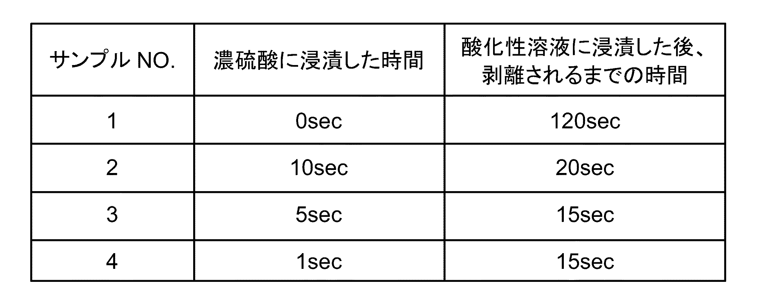
表1に示すように、高濃度の無機酸溶液(硫酸濃度が98重量パーセントの濃硫酸溶液)に浸漬させない場合は(サンプルNO.1の場合)、レジストが剥離されるまでに120秒かかる。これに対し、高濃度の無機酸溶液(硫酸濃度が98重量パーセントの濃硫酸溶液)に浸漬させた場合は(サンプルNO.2〜4の場合)、レジストが剥離されるまでに20秒程度しかかからず処理時間(剥離時間)の大幅な短縮が図れることがわかる。また、高濃度の無機酸溶液(硫酸濃度が98重量パーセントの濃硫酸溶液)に浸漬させる時間は短くても、レジストが剥離されるまでの時間には大きな影響がないこともわかる。
As shown in Table 1, when not immersed in a highly concentrated inorganic acid solution (concentrated sulfuric acid solution having a sulfuric acid concentration of 98 weight percent) (in the case of sample No. 1), it takes 120 seconds for the resist to be stripped. In contrast, when immersed in a high-concentration inorganic acid solution (concentrated sulfuric acid solution having a sulfuric acid concentration of 98 weight percent) (in the case of sample Nos. 2 to 4), it takes only about 20 seconds until the resist is peeled off. It can be seen that the processing time (peeling time) can be greatly shortened. It can also be seen that even if the time for dipping in a high-concentration inorganic acid solution (concentrated sulfuric acid solution having a sulfuric acid concentration of 98 weight percent) is short, the time until the resist is stripped is not significantly affected.
図5は、順次供給する回数と剥離時間との関係を例示するためのグラフ図である。尚、縦軸はサンプルNOを表し、横軸は試験片表面に形成されたレジストが剥離されるまでの時間(剥離時間)を表している。また、図中のD1は硫酸濃度が98重量パーセントの濃硫酸溶液に浸漬させる場合を表し、D2は硫酸濃度が70重量パーセントの希釈硫酸溶液を電気分解することで生成された酸化性溶液に浸漬させる場合を表している。また、硫酸濃度が98重量パーセントの濃硫酸溶液、酸化性溶液の温度は、一例として、100〜110℃程度とした。 FIG. 5 is a graph for illustrating the relationship between the number of times of sequential supply and the peeling time. The vertical axis represents the sample NO, and the horizontal axis represents the time until the resist formed on the surface of the test piece is peeled (peeling time). Further, D1 in the figure represents a case where the sulfuric acid concentration is immersed in a concentrated sulfuric acid solution having a 98 weight percent sulfuric acid, and D2 is immersed in an oxidizing solution generated by electrolyzing a diluted sulfuric acid solution having a sulfuric acid concentration of 70 weight percent. This represents the case where Moreover, the temperature of the concentrated sulfuric acid solution with a sulfuric acid concentration of 98 weight percent and an oxidizing solution was about 100-110 degreeC as an example.
サンプルNO.10は、硫酸濃度が98重量パーセントの濃硫酸溶液に1秒浸漬させることを1回行った場合である(D1の部分)。この場合は、レジストが剥離されるまでに16秒程度かかることがわかる。
サンプルNO.11は、硫酸濃度が98重量パーセントの濃硫酸溶液に1秒浸漬させること(D1の部分)と、酸化性溶液に4秒浸漬させること(D2の部分)を順次行った場合である。この場合、硫酸濃度が98重量パーセントの濃硫酸溶液に浸漬させる回数が2回、酸化性溶液に浸漬させる回数が2回の時点でレジストが剥離された。そして、レジストが剥離されるまでの時間は10秒となり、処理時間が短縮できることがわかる。
Sample No. No. 10 is a case where immersion in a concentrated sulfuric acid solution having a sulfuric acid concentration of 98 weight percent for 1 second was performed once (part D1). In this case, it is understood that it takes about 16 seconds for the resist to be peeled off.
Sample No. 11 is a case where immersion in a concentrated sulfuric acid solution having a sulfuric acid concentration of 98 weight percent for 1 second (part D1) and immersion in an oxidizing solution for 4 seconds (part D2) were sequentially performed. In this case, the resist was peeled off when the sulfuric acid concentration was immersed twice in the concentrated sulfuric acid solution with 98 weight percent and the oxidizing solution was immersed twice. It can be seen that the time until the resist is stripped is 10 seconds, and the processing time can be shortened.
サンプルNO.12は、硫酸濃度が98重量パーセントの濃硫酸溶液に1秒浸漬させること(D1の部分)と、酸化性溶液に1秒浸漬させること(D2の部分)を順次行った場合である。この場合、98重量パーセントの濃硫酸溶液に浸漬させる回数が4回、酸化性溶液に浸漬させる回数が4回の時点でレジストが剥離された。そして、レジストが剥離されるまでの時間は8秒となり、処理時間がさらに短縮できることがわかる。 Sample No. No. 12 is a case where immersion in a concentrated sulfuric acid solution having a sulfuric acid concentration of 98 weight percent for 1 second (part D1) and immersion in an oxidizing solution for 1 second (part D2) were sequentially performed. In this case, the resist was peeled off when the number of immersions in the 98 weight percent concentrated sulfuric acid solution was four and the number of immersions in the oxidizing solution was four. The time until the resist is peeled is 8 seconds, and it can be seen that the processing time can be further shortened.
このように、浸漬させる回数を増やし順次繰り返すようにした方が処理時間を短縮することができる。また、表1において例示をしたように浸漬させる時間は短くても、レジストが剥離されるまでの時間には大きな影響がない。そのため、ある程度短い時間の浸漬を繰り返すように行った方が処理時間の短縮を図れることになる。 As described above, the processing time can be shortened by increasing the number of times of immersion and sequentially repeating the immersion. Further, as illustrated in Table 1, even if the immersion time is short, the time until the resist is peeled off is not greatly affected. Therefore, the treatment time can be shortened by repeating soaking for a relatively short time.
図6は、処理温度(溶液温度)の影響を例示するためのグラフ図である。尚、縦軸はサンプルNOを表し、横軸は試験片表面に形成されたレジストが剥離されるまでの時間(剥離時間)を表している。また、図中のE1は硫酸濃度が98重量パーセントの濃硫酸溶液に浸漬させる場合を表し、E2は硫酸濃度が70重量パーセントの希釈硫酸溶液を電気分解することで生成された酸化性溶液に浸漬させる場合を表している。
サンプルNO.20は、硫酸濃度が98重量パーセントの濃硫酸溶液の温度を室温とし、酸化性溶液の温度を75℃とした場合である。そして、硫酸濃度が98重量パーセントの濃硫酸溶液に5秒間浸漬させた後、酸化性溶液に浸漬させることでレジストの剥離を行った場合である。この場合のレジストが剥離するまでの時間は520秒であった。
FIG. 6 is a graph for illustrating the influence of the processing temperature (solution temperature). The vertical axis represents the sample NO, and the horizontal axis represents the time until the resist formed on the surface of the test piece is peeled (peeling time). Further, E1 in the figure represents the case where the sulfuric acid concentration is immersed in a concentrated sulfuric acid solution having a 98 weight percent sulfuric acid, and E2 is immersed in an oxidizing solution generated by electrolyzing a diluted sulfuric acid solution having a sulfuric acid concentration of 70 weight percent. This represents the case where
Sample No. 20 is a case where the temperature of the concentrated sulfuric acid solution having a sulfuric acid concentration of 98 weight percent is set to room temperature and the temperature of the oxidizing solution is set to 75 ° C. In this case, the resist is peeled off by immersing in a concentrated sulfuric acid solution having a sulfuric acid concentration of 98 weight percent for 5 seconds and then in an oxidizing solution. In this case, the time until the resist peeled was 520 seconds.
サンプルNO.21は、硫酸濃度が98重量パーセントの濃硫酸溶液の温度を75℃とし、酸化性溶液の温度を75℃とした場合である。そして、硫酸濃度が98重量パーセントの濃硫酸溶液に5秒間浸漬させた後、酸化性溶液に浸漬させることでレジストの剥離を行った場合である。この場合のレジストが剥離するまでの時間は360秒であった。 Sample No. 21 is the case where the temperature of the concentrated sulfuric acid solution having a sulfuric acid concentration of 98 weight percent is 75 ° C. and the temperature of the oxidizing solution is 75 ° C. In this case, the resist is peeled off by immersing in a concentrated sulfuric acid solution having a sulfuric acid concentration of 98 weight percent for 5 seconds and then in an oxidizing solution. In this case, the time until the resist peeled was 360 seconds.
サンプルNO.22は、硫酸濃度が98重量パーセントの濃硫酸溶液の温度を100℃とし、酸化性溶液の温度を75℃とした場合である。そして、硫酸濃度が98重量パーセントの濃硫酸溶液に5秒間浸漬させた後、酸化性溶液に浸漬させることでレジストの剥離を行った場合である。この場合のレジストが剥離するまでの時間は80秒であった。 Sample No. No. 22 is a case where the temperature of the concentrated sulfuric acid solution having a sulfuric acid concentration of 98 weight percent is 100 ° C., and the temperature of the oxidizing solution is 75 ° C. In this case, the resist is peeled off by immersing in a concentrated sulfuric acid solution having a sulfuric acid concentration of 98 weight percent for 5 seconds and then in an oxidizing solution. In this case, the time until the resist peeled was 80 seconds.
サンプルNO.23は、硫酸濃度が98重量パーセントの濃硫酸溶液の温度を100℃とし、酸化性溶液の温度を100℃とした場合である。そして、硫酸濃度が98重量パーセントの濃硫酸溶液に5秒間浸漬させた後、酸化性溶液に浸漬させることでレジストの剥離を行った場合である。この場合のレジストが剥離するまでの時間は20秒であった。 Sample No. No. 23 is a case where the temperature of the concentrated sulfuric acid solution having a sulfuric acid concentration of 98 weight percent is 100 ° C. and the temperature of the oxidizing solution is 100 ° C. In this case, the resist is peeled off by immersing in a concentrated sulfuric acid solution having a sulfuric acid concentration of 98 weight percent for 5 seconds and then in an oxidizing solution. In this case, the time until the resist peeled was 20 seconds.
このように、処理温度(溶液温度)を上げるほど処理時間の短縮を図ることができるが、温度があまりたかくなると洗浄システムの各構成要素(例えば、各部の管路、開閉弁、ポンプ、タンク、洗浄処理部のカバーなど)の耐熱温度や強度が問題となるおそれがある。高濃度の無機酸溶液や酸化性溶液と接触する部分は耐薬品性を高めるために、例えば、フッ素系樹脂などで形成される場合が多い。このような場合、温度を高くしすぎると必要な強度が得られなくなるおそれがある。
そのため、処理時間の短縮と洗浄システム側の耐熱温度や強度などを考慮すれば、高濃度の無機酸溶液、酸化性溶液の温度は100℃以上、110℃以下とすることが好ましい。この場合、前述した反応熱を利用するものとすれば、洗浄システムの熱的負担を軽減させつつ処理温度(溶液温度)をさらに高めることができる。反応熱を利用するものとすれば、処理温度(溶液温度)を100℃以上、150℃以下とすることができる。
In this way, the processing time can be shortened as the processing temperature (solution temperature) is increased. However, when the temperature becomes too high, each component of the cleaning system (for example, pipes of each part, on-off valves, pumps, tanks, The heat-resistant temperature and strength of the cleaning processing unit cover, etc.) may become a problem. In order to improve chemical resistance, a portion that comes into contact with a high concentration inorganic acid solution or oxidizing solution is often formed of, for example, a fluorine resin. In such a case, if the temperature is too high, the required strength may not be obtained.
Therefore, considering the shortening of the processing time and the heat-resistant temperature and strength on the cleaning system side, the temperature of the highly concentrated inorganic acid solution and oxidizing solution is preferably 100 ° C. or higher and 110 ° C. or lower. In this case, if the reaction heat described above is used, the treatment temperature (solution temperature) can be further increased while reducing the thermal burden on the cleaning system. If reaction heat is used, the processing temperature (solution temperature) can be set to 100 ° C. or higher and 150 ° C. or lower.
次に、本実施の形態に係る洗浄方法について例示をする。
図7は、洗浄方法について例示をするためのフローチャートである。
まず、希釈硫酸溶液を電気分解することで酸化性物質(例えば、ペルオキソ一硫酸、ペルオキソ二硫酸)を含む酸化性溶液を生成する(ステップS1−1)。この場合、希釈硫酸溶液の硫酸濃度を30重量パーセント以上、70重量パーセント以下とすれば、効率よく酸化性物質を生成することができる。
Next, the cleaning method according to this embodiment will be illustrated.
FIG. 7 is a flowchart for illustrating the cleaning method.
First, an oxidized solution containing an oxidizing substance (for example, peroxomonosulfuric acid or peroxodisulfuric acid) is generated by electrolyzing the diluted sulfuric acid solution (step S1-1). In this case, if the sulfuric acid concentration of the diluted sulfuric acid solution is 30 weight percent or more and 70 weight percent or less, an oxidizing substance can be efficiently generated.
次に、生成された酸化性溶液の温度を調整する(ステップS1−2)。この温度調整は必ずしも必要ではないが、前述したように溶液の温度が100℃以上、110℃以下となるように調整することが好ましい。尚、温度調整は、生成された酸化性溶液、酸化性溶液の生成時(電気分解時)、電気分解のために供給される希釈硫酸溶液のいずれかに対して行うようにすることができる。 Next, the temperature of the generated oxidizing solution is adjusted (step S1-2). Although this temperature adjustment is not necessarily required, it is preferable to adjust the temperature of the solution to be 100 ° C. or higher and 110 ° C. or lower as described above. It should be noted that the temperature adjustment can be performed on any of the generated oxidizing solution, the oxidizing solution generated (electrolysis), or the diluted sulfuric acid solution supplied for electrolysis.
また、高濃度の無機酸溶液の温度を調整する(ステップS2)。高濃度の無機酸溶液としては、例えば、無機酸濃度が90重量パーセント以上の無機酸溶液を例示することができる。例えば、硫酸濃度が90重量パーセント以上の濃硫酸溶液などとすることができる。この温度調整は必ずしも必要ではないが、前述したように温度が100℃以上、110℃以下となるように調整することが好ましい。 Further, the temperature of the high concentration inorganic acid solution is adjusted (step S2). Examples of the high concentration inorganic acid solution include an inorganic acid solution having an inorganic acid concentration of 90 weight percent or more. For example, a concentrated sulfuric acid solution having a sulfuric acid concentration of 90 weight percent or more can be used. Although this temperature adjustment is not always necessary, it is preferable to adjust the temperature to be 100 ° C. or higher and 110 ° C. or lower as described above.
次に、高濃度の無機酸溶液と酸化性溶液とを洗浄対象物Wの表面に、個別に、順次または略同時に供給する(ステップS3)。尚、供給は、ノズルなどから洗浄対象物W毎に行われるようにしてもよいし、高濃度の無機酸溶液と酸化性溶液とに順次浸漬させるようにしてもよい。また、例えば、高濃度の無機酸溶液と酸化性溶液とを別々の配管系統から個別に、順次または略同時に供給してもよい。また、いわゆる枚葉処理方式、バッチ処理方式などとすることもできる。
また、洗浄対象物Wの表面に対して、高濃度の無機酸溶液(例えば、濃硫酸)を供給して行う処理と、酸化性物質を含む酸化性溶液(例えば、希釈硫酸の電解により生成した電解硫酸)を供給して行う処理とを所定の回数だけ繰り返し行うようにすれば、処理時間(剥離時間)をさらに短縮することができる。
この場合、高濃度の無機酸溶液の供給と、酸化性溶液の供給と、の間にはリンス液を洗浄対象物Wの表面に供給する工程を設ける必要はない。そのため、製造工程の簡素化を図ることができるとともに処理時間(剥離時間)の短縮を図ることができる。
Next, a high-concentration inorganic acid solution and an oxidizing solution are supplied to the surface of the cleaning object W individually, sequentially or substantially simultaneously (step S3). The supply may be performed for each cleaning object W from a nozzle or the like, or may be sequentially immersed in a high-concentration inorganic acid solution and an oxidizing solution. In addition, for example, the high-concentration inorganic acid solution and the oxidizing solution may be supplied separately or sequentially from separate piping systems. Also, a so-called single wafer processing method, batch processing method, or the like can be used.
Further, the surface of the cleaning object W is generated by supplying a high-concentration inorganic acid solution (for example, concentrated sulfuric acid) and an oxidizing solution containing an oxidizing substance (for example, electrolysis of diluted sulfuric acid). If the treatment performed by supplying (electrolytic sulfuric acid) is repeated a predetermined number of times, the treatment time (peeling time) can be further shortened.
In this case, it is not necessary to provide a step of supplying the rinse liquid to the surface of the cleaning object W between the supply of the high-concentration inorganic acid solution and the supply of the oxidizing solution. Therefore, the manufacturing process can be simplified and the processing time (peeling time) can be shortened.
図8は、他の実施の形態に係る洗浄方法について例示をするためのフローチャートである。
本実施の形態においては、酸化性溶液と高濃度の無機酸溶液とを混合し、これを洗浄対象物Wの表面に供給するようにしている。
FIG. 8 is a flowchart for illustrating a cleaning method according to another embodiment.
In the present embodiment, an oxidizing solution and a high-concentration inorganic acid solution are mixed and supplied to the surface of the cleaning object W.
まず、希釈硫酸溶液を電気分解することで酸化性物質(例えば、ペルオキソ一硫酸、ペルオキソ二硫酸)を含む酸化性溶液を生成する(ステップS10)。この場合、希釈硫酸の硫酸濃度を30重量パーセント以上、70重量パーセント以下とすれば、効率よく酸化性物質を生成することができる。 First, an oxidized solution containing an oxidizing substance (for example, peroxomonosulfuric acid or peroxodisulfuric acid) is generated by electrolyzing the diluted sulfuric acid solution (step S10). In this case, when the sulfuric acid concentration of the diluted sulfuric acid is set to 30% by weight or more and 70% by weight or less, the oxidizing substance can be efficiently generated.
次に、酸化性溶液と高濃度の無機酸溶液とを混合し、洗浄液を生成する(ステップS11)。この際、洗浄液中の無機酸濃度や酸化性物質の量が適宜調整される。高濃度の無機酸溶液としては、例えば、無機酸濃度が90重量パーセント以上の無機酸溶液を例示することができる。例えば、硫酸濃度が90重量パーセント以上の濃硫酸溶液などとすることができる。 Next, the oxidizing solution and the high-concentration inorganic acid solution are mixed to generate a cleaning liquid (step S11). At this time, the concentration of the inorganic acid and the amount of the oxidizing substance in the cleaning liquid are appropriately adjusted. Examples of the high concentration inorganic acid solution include an inorganic acid solution having an inorganic acid concentration of 90 weight percent or more. For example, a concentrated sulfuric acid solution having a sulfuric acid concentration of 90 weight percent or more can be used.
次に、生成された洗浄液の温度を調整する(ステップS12)。この温度調整は必ずしも必要ではないが、前述したように洗浄液の温度が100℃以上、110℃以下となるように調整することが好ましい。尚、温度調整は、混合前の酸化性溶液、高濃度の無機酸溶液に対して行うこともできる。 Next, the temperature of the generated cleaning liquid is adjusted (step S12). Although this temperature adjustment is not necessarily required, it is preferable to adjust the temperature of the cleaning liquid to be 100 ° C. or higher and 110 ° C. or lower as described above. In addition, temperature adjustment can also be performed with respect to the oxidizing solution before mixing and a high concentration inorganic acid solution.
次に、洗浄液(高濃度の無機酸溶液と酸化性溶液との混合液)を洗浄対象物Wの表面に供給する(ステップS13)。尚、供給は、ノズルなどから洗浄対象物W毎に行われるようにしてもよいし、洗浄液に浸漬させるようにしてもよい。また、いわゆる枚葉処理方式、バッチ処理方式などとすることもできる。 Next, a cleaning liquid (a mixed liquid of a high-concentration inorganic acid solution and an oxidizing solution) is supplied to the surface of the cleaning object W (step S13). The supply may be performed for each cleaning object W from a nozzle or the like, or may be immersed in the cleaning liquid. Also, a so-called single wafer processing method, batch processing method, or the like can be used.
図7、図8に例示をしたように、本実施の形態においては希釈硫酸溶液を電気分解しているため電解効率が高く、より多くの酸化性物質を効率よく生成することができる。この場合、酸化性物質の生成後(電気分解の後)に高濃度の無機酸溶液と酸化性溶液とが混合されるので、電解効率に影響を与えることがない。
また、高濃度の無機酸溶液により無機酸の濃度が高い洗浄液、または、無機酸の濃度の高い洗浄対象物W表面での処理とすることができる。
そのため、硫酸などの無機酸の濃度が高く、含まれる酸化性物質の量が多い処理(洗浄)を行うことができるので処理時間(剥離時間)を大幅に短縮することができる。
As illustrated in FIGS. 7 and 8, in the present embodiment, since the diluted sulfuric acid solution is electrolyzed, the electrolysis efficiency is high, and more oxidizing substances can be efficiently generated. In this case, since the high-concentration inorganic acid solution and the oxidizing solution are mixed after the generation of the oxidizing substance (after the electrolysis), the electrolytic efficiency is not affected.
Moreover, it can be set as the process in the washing | cleaning liquid with a high density | concentration of an inorganic acid by the high concentration inorganic acid solution, or the washing | cleaning target object W surface with a high density | concentration of an inorganic acid.
Therefore, the treatment (cleaning) with a high concentration of inorganic acid such as sulfuric acid and a large amount of the oxidizable substance can be performed, so that the treatment time (peeling time) can be greatly shortened.
また、高速動作用半導体装置は、高いドーズ量の不純物を注入して製造されているが、高いドーズ量の不純物を注入すれば、レジストの表面に変質層が形成される。このような変質層が形成されたレジストは剥離が難しく、所望の剥離マージンが得られないという問題がある。 In addition, a semiconductor device for high-speed operation is manufactured by implanting a high dose of impurities. However, if a high dose of impurities is implanted, an altered layer is formed on the surface of the resist. The resist having such a deteriorated layer is difficult to peel off, and there is a problem that a desired peeling margin cannot be obtained.
本実施の形態によれば、高濃度の無機酸と酸化性物質を多く含む溶液を洗浄対象物Wの表面に供給することができるので、変質層が形成されたレジストであってもその剥離性を向上させることができる。 According to the present embodiment, since a solution containing a large amount of high-concentration inorganic acid and oxidizing substance can be supplied to the surface of the object to be cleaned W, even if the resist has an altered layer, its peelability Can be improved.
また、洗浄対象物Wに供給される前、あるいは洗浄対象物W上で、高濃度の無機酸溶液と低濃度の無機酸溶液でもある酸化性溶液とを混合させることで反応熱を生じさせることができる。そのため、洗浄システムの各構成要素の温度上昇を抑制することができるとともに、混合された液の温度を高めることで酸化性物質の反応性を高めることができる。その結果、処理時間(剥離時間)をさらに短縮することができる。 Also, before being supplied to the cleaning object W or on the cleaning object W, a reaction heat is generated by mixing a high concentration inorganic acid solution and an oxidizing solution which is also a low concentration inorganic acid solution. Can do. Therefore, the temperature rise of each component of the cleaning system can be suppressed, and the reactivity of the oxidizing substance can be increased by increasing the temperature of the mixed liquid. As a result, the processing time (peeling time) can be further shortened.
次に、本実施の形態に係る微細構造体の製造方法について例示をする。
微細構造体の製造方法としては、例えば、半導体装置の製造方法を例示することができる。ここで、半導体装置の製造工程には、いわゆる前工程における成膜・レジスト塗布・露光・現像・エッチング・レジスト除去などにより基板(ウェーハ)表面にパターンを形成する工程、検査工程、洗浄工程、熱処理工程、不純物導入工程、拡散工程、平坦化工程などがある。また、いわゆる後工程においては、ダイシング、マウンティング、ボンディング、封入などの組立工程、機能や信頼性の検査工程などがある。
Next, a method for manufacturing the microstructure according to this embodiment is illustrated.
As a manufacturing method of the fine structure, for example, a manufacturing method of a semiconductor device can be exemplified. Here, in the manufacturing process of a semiconductor device, a process of forming a pattern on a substrate (wafer) surface by film formation, resist coating, exposure, development, etching, resist removal, etc. in a so-called previous process, an inspection process, a cleaning process, and a heat treatment There are a process, an impurity introduction process, a diffusion process, a planarization process, and the like. In the so-called post-process, there are an assembly process such as dicing, mounting, bonding, and encapsulation, and a function and reliability inspection process.
この場合、例えば、レジスト除去工程において前述した洗浄方法や洗浄システムを用いることで迅速なレジスト除去(剥離)を行うことができる。尚、前述した本実施の形態に係る洗浄方法や洗浄システム以外のものは、各工程における既知の技術を適用できるので、それらの詳細な説明は省略する。 In this case, for example, the resist removal (peeling) can be quickly performed by using the above-described cleaning method or cleaning system in the resist removal step. It should be noted that since the techniques other than the cleaning method and the cleaning system according to the present embodiment described above can apply known techniques in each step, detailed description thereof will be omitted.
また、微細構造体の製造方法の一例として、半導体装置の製造方法を例示したがこれに限定されるわけではない。例えば、液晶表示装置、位相シフトマスク、MEMS分野におけるマイクロマシーン、精密光学部品などの分野においても適応が可能である。 Moreover, although the manufacturing method of the semiconductor device was illustrated as an example of the manufacturing method of a fine structure, it is not necessarily limited to this. For example, the present invention can be applied to fields such as liquid crystal display devices, phase shift masks, micromachines in the MEMS field, and precision optical components.
また、前述した洗浄システムにおいて、溶液の循環構成は必ずしも設けなくてもよく、図9に表すように、洗浄処理部12で使用された使用済みの溶液を汚染物などと一緒に回収タンク63に一旦回収した後、排出管路75を介して系外に排出するようにしてもよい。
Further, in the above-described cleaning system, the solution circulation structure is not necessarily provided. As shown in FIG. 9, the used solution used in the
また、有機物からなるレジストの除去だけでなく、金属不純物の除去、パーティクル除去、ドライエッチング残渣の除去にも、同様に使用することができる。 Moreover, it can be similarly used not only for removing resists made of organic substances but also for removing metal impurities, particles, and dry etching residues.
また、洗浄対象物を搬送するためのロボットを設けてもよい。また、希釈硫酸溶液を貯留するタンク60や高濃度の無機酸溶液を貯留するタンク51は、それぞれ工場のラインに接続させて溶液が自動的に補給されるようにしてもよい。また、汚染物を除去した洗浄対象物をリンス処理するリンス槽を設けてもよい。このリンス槽には、オーバフロー制御機器やインラインヒータによる温度制御機器を設けることができる。リンス槽の材質としては、石英を用いるとよい。
Moreover, you may provide the robot for conveying a washing | cleaning target object. Further, the
ただし、高濃度の無機酸溶液(例えば、濃硫酸)の供給と、酸化性溶液(例えば、希釈硫酸の電解により生成した電解硫酸)の供給と、の間にはリンス液を洗浄対象物の表面に供給する工程を設ける必要はない。洗浄対象物Wに対して、高濃度の無機酸溶液(例えば、濃硫酸)を供給して行う処理と、酸化性物質を含む酸化性溶液(例えば、希釈硫酸の電解により生成した電解硫酸)を供給して行う処理とを所定の回数だけ繰り返し行うようにすればよい。そのため、製造工程の簡素化を図ることができるとともに処理時間(剥離時間)の短縮を図ることができる。 However, a rinsing liquid is provided between the supply of the high-concentration inorganic acid solution (for example, concentrated sulfuric acid) and the supply of the oxidizing solution (for example, electrolytic sulfuric acid generated by electrolysis of diluted sulfuric acid) to the surface of the object to be cleaned. There is no need to provide a process for supplying to. A treatment performed by supplying a highly concentrated inorganic acid solution (for example, concentrated sulfuric acid) to the object W to be cleaned, and an oxidizing solution containing an oxidizing substance (for example, electrolytic sulfuric acid generated by electrolysis of diluted sulfuric acid) What is necessary is just to repeat the process performed by supplying a predetermined number of times. Therefore, the manufacturing process can be simplified and the processing time (peeling time) can be shortened.
以上、本発明の実施の形態について例示をした。しかし、本発明はこれらの記述に限定されるものではない。
前述の実施の形態に関して、当業者が適宜設計変更を加えたものも、本発明の特徴を備えている限り、本発明の範囲に包含される。
The embodiment of the present invention has been illustrated above. However, the present invention is not limited to these descriptions.
As long as the features of the present invention are provided, those skilled in the art appropriately modified the design of the above-described embodiments are also included in the scope of the present invention.
例えば、前述した洗浄システムが備える各要素の形状、寸法、材質、配置などは、例示したものに限定されるわけではなく適宜変更することができる。
また、前述した各実施の形態が備える各要素は、可能な限りにおいて組み合わせることができ、これらを組み合わせたものも本発明の特徴を含む限り本発明の範囲に包含される。
For example, the shape, size, material, arrangement, and the like of each element included in the above-described cleaning system are not limited to those illustrated, but can be changed as appropriate.
Moreover, each element with which each embodiment mentioned above is combined can be combined as much as possible, and what combined these is also included in the scope of the present invention as long as the characteristics of the present invention are included.
5 洗浄システム、10 硫酸電解部、12 洗浄処理部、14 溶液循環部、15 希釈硫酸供給部、20 隔膜、30 陽極室、32 陽極、40 陰極室、42 陰極、50 無機酸供給部 5 cleaning system, 10 sulfuric acid electrolysis unit, 12 cleaning processing unit, 14 solution circulation unit, 15 diluted sulfuric acid supply unit, 20 diaphragm, 30 anode chamber, 32 anode, 40 cathode chamber, 42 cathode, 50 inorganic acid supply unit
Claims (1)
硫酸濃度が90重量パーセント以上の硫酸溶液と、前記酸化性溶液と、を混合して反応熱を発生させる工程と、
前記反応熱により加熱された前記硫酸溶液および前記酸化性溶液により、表面に変質層が形成されたレジストを有する洗浄対象物を洗浄する工程と、
を備え、
前記反応熱を発生させる工程における混合は、前記洗浄対象物の表面で行われ、
前記洗浄対象物の表面に、前記硫酸溶液を供給し、前記硫酸溶液の供給の後に前記酸化性溶液を供給すること、を繰り返して行うこと、を特徴とする洗浄方法。 Electrolyzing a sulfuric acid solution having a sulfuric acid concentration of 30 weight percent or more and 70 weight percent or less to produce an oxidizing solution containing an oxidizing substance;
A step of mixing a sulfuric acid solution having a sulfuric acid concentration of 90 weight percent or more and the oxidizing solution to generate heat of reaction;
A step of cleaning an object to be cleaned having a resist having a deteriorated layer formed on the surface with the sulfuric acid solution and the oxidizing solution heated by the reaction heat;
With
Mixed in the step of generating the reaction heat is carried out at the surface of the pre-Symbol cleaned object,
A cleaning method comprising: repeatedly supplying the sulfuric acid solution to the surface of the object to be cleaned, and supplying the oxidizing solution after supplying the sulfuric acid solution .
Priority Applications (5)
| Application Number | Priority Date | Filing Date | Title |
|---|---|---|---|
| JP2009220127A JP5148576B2 (en) | 2009-09-25 | 2009-09-25 | Cleaning method |
| US12/880,549 US20110073490A1 (en) | 2009-09-25 | 2010-09-13 | Cleaning method, cleaning system, and method for manufacturing microstructure |
| TW099130901A TWI442464B (en) | 2009-09-25 | 2010-09-13 | Cleaning method, cleaning system, and method for manufacturing microstructure |
| KR1020100091630A KR101165918B1 (en) | 2009-09-25 | 2010-09-17 | Cleaning method, cleaning system, and method for manufacturing microstructure |
| CN201010287644.5A CN102030306B (en) | 2009-09-25 | 2010-09-20 | Cleaning method, cleaning system, and method for manufacturing microstructure |
Applications Claiming Priority (1)
| Application Number | Priority Date | Filing Date | Title |
|---|---|---|---|
| JP2009220127A JP5148576B2 (en) | 2009-09-25 | 2009-09-25 | Cleaning method |
Publications (2)
| Publication Number | Publication Date |
|---|---|
| JP2011068944A JP2011068944A (en) | 2011-04-07 |
| JP5148576B2 true JP5148576B2 (en) | 2013-02-20 |
Family
ID=43779101
Family Applications (1)
| Application Number | Title | Priority Date | Filing Date |
|---|---|---|---|
| JP2009220127A Active JP5148576B2 (en) | 2009-09-25 | 2009-09-25 | Cleaning method |
Country Status (5)
| Country | Link |
|---|---|
| US (1) | US20110073490A1 (en) |
| JP (1) | JP5148576B2 (en) |
| KR (1) | KR101165918B1 (en) |
| CN (1) | CN102030306B (en) |
| TW (1) | TWI442464B (en) |
Families Citing this family (28)
| Publication number | Priority date | Publication date | Assignee | Title |
|---|---|---|---|---|
| JP5106523B2 (en) * | 2009-12-16 | 2012-12-26 | 株式会社東芝 | Etching method, microstructure manufacturing method, and etching apparatus |
| KR101918639B1 (en) | 2012-01-03 | 2018-11-15 | 삼성전자주식회사 | Semiconductor device and forming the same |
| US20130260569A1 (en) * | 2012-03-30 | 2013-10-03 | Lam Research Ag | Apparatus and method for liquid treatment of wafer-shaped articles |
| JP5657620B2 (en) * | 2012-09-04 | 2015-01-21 | 株式会社東芝 | Processing apparatus and processing method |
| JP2014062297A (en) * | 2012-09-20 | 2014-04-10 | Toshiba Corp | Processing apparatus, method for producing processing liquid, and method for producing electronic device |
| CN102916075A (en) * | 2012-09-27 | 2013-02-06 | 奥特斯维能源(太仓)有限公司 | Method for stabilizing wool-making depth |
| US8867343B2 (en) | 2013-03-15 | 2014-10-21 | Extrahop Networks, Inc. | Trigger based recording of flows with play back |
| US8626912B1 (en) | 2013-03-15 | 2014-01-07 | Extrahop Networks, Inc. | Automated passive discovery of applications |
| US9338147B1 (en) | 2015-04-24 | 2016-05-10 | Extrahop Networks, Inc. | Secure communication secret sharing |
| US10204211B2 (en) | 2016-02-03 | 2019-02-12 | Extrahop Networks, Inc. | Healthcare operations with passive network monitoring |
| US9729416B1 (en) | 2016-07-11 | 2017-08-08 | Extrahop Networks, Inc. | Anomaly detection using device relationship graphs |
| CN106055016B (en) * | 2016-07-22 | 2017-11-28 | 清华大学 | surface potential control device and control method |
| US9660879B1 (en) | 2016-07-25 | 2017-05-23 | Extrahop Networks, Inc. | Flow deduplication across a cluster of network monitoring devices |
| US10476673B2 (en) | 2017-03-22 | 2019-11-12 | Extrahop Networks, Inc. | Managing session secrets for continuous packet capture systems |
| US10263863B2 (en) | 2017-08-11 | 2019-04-16 | Extrahop Networks, Inc. | Real-time configuration discovery and management |
| US10063434B1 (en) | 2017-08-29 | 2018-08-28 | Extrahop Networks, Inc. | Classifying applications or activities based on network behavior |
| US9967292B1 (en) | 2017-10-25 | 2018-05-08 | Extrahop Networks, Inc. | Inline secret sharing |
| US10389574B1 (en) | 2018-02-07 | 2019-08-20 | Extrahop Networks, Inc. | Ranking alerts based on network monitoring |
| US10264003B1 (en) | 2018-02-07 | 2019-04-16 | Extrahop Networks, Inc. | Adaptive network monitoring with tuneable elastic granularity |
| US10038611B1 (en) | 2018-02-08 | 2018-07-31 | Extrahop Networks, Inc. | Personalization of alerts based on network monitoring |
| US10116679B1 (en) | 2018-05-18 | 2018-10-30 | Extrahop Networks, Inc. | Privilege inference and monitoring based on network behavior |
| US10411978B1 (en) | 2018-08-09 | 2019-09-10 | Extrahop Networks, Inc. | Correlating causes and effects associated with network activity |
| US10594718B1 (en) | 2018-08-21 | 2020-03-17 | Extrahop Networks, Inc. | Managing incident response operations based on monitored network activity |
| US10965702B2 (en) | 2019-05-28 | 2021-03-30 | Extrahop Networks, Inc. | Detecting injection attacks using passive network monitoring |
| US11165814B2 (en) | 2019-07-29 | 2021-11-02 | Extrahop Networks, Inc. | Modifying triage information based on network monitoring |
| US11165823B2 (en) | 2019-12-17 | 2021-11-02 | Extrahop Networks, Inc. | Automated preemptive polymorphic deception |
| US11349861B1 (en) | 2021-06-18 | 2022-05-31 | Extrahop Networks, Inc. | Identifying network entities based on beaconing activity |
| US12483384B1 (en) | 2025-04-16 | 2025-11-25 | Extrahop Networks, Inc. | Resynchronizing encrypted network traffic |
Family Cites Families (13)
| Publication number | Priority date | Publication date | Assignee | Title |
|---|---|---|---|---|
| CA1059943A (en) * | 1976-07-20 | 1979-08-07 | Pierre L. Claessens | Electrolytically forming peroxosulfuric acid to oxidize organic material in sulfuric acid |
| JPS60173841A (en) * | 1984-02-20 | 1985-09-07 | Oki Electric Ind Co Ltd | Washer for substrate |
| JP3377294B2 (en) * | 1994-06-03 | 2003-02-17 | 大日本スクリーン製造株式会社 | Substrate surface treatment method and apparatus |
| US20050139487A1 (en) * | 2003-05-02 | 2005-06-30 | Fraunhofer-Gesellschaft Zur Forderung Der Angewandten Forschung E.V. | Method for the oxidative treatment of components comprised of or containing elementary silicon and/or substantially inorganic silicon compounds |
| JP4462146B2 (en) | 2004-09-17 | 2010-05-12 | 栗田工業株式会社 | Sulfuric acid recycling type cleaning system and sulfuric acid recycling type persulfuric acid supply device |
| JP2007266497A (en) * | 2006-03-29 | 2007-10-11 | Kurita Water Ind Ltd | Semiconductor substrate cleaning system |
| US20070227556A1 (en) * | 2006-04-04 | 2007-10-04 | Bergman Eric J | Methods for removing photoresist |
| US8303797B2 (en) * | 2006-06-16 | 2012-11-06 | Kabushiki Kaisha Toshiba | Cleaning system and cleaning method |
| JP5087325B2 (en) * | 2006-06-16 | 2012-12-05 | 株式会社東芝 | Cleaning system and cleaning method |
| JP4644170B2 (en) * | 2006-09-06 | 2011-03-02 | 栗田工業株式会社 | Substrate processing apparatus and substrate processing method |
| JP5148889B2 (en) | 2007-02-09 | 2013-02-20 | 株式会社東芝 | Cleaning method and electronic device manufacturing method |
| JP5126478B2 (en) * | 2007-03-28 | 2013-01-23 | 栗田工業株式会社 | Cleaning liquid manufacturing method, cleaning liquid supply apparatus and cleaning system |
| CN101477096B (en) * | 2009-01-05 | 2012-11-21 | 大连理工大学 | Polymer plane nano-channel production method |
-
2009
- 2009-09-25 JP JP2009220127A patent/JP5148576B2/en active Active
-
2010
- 2010-09-13 TW TW099130901A patent/TWI442464B/en active
- 2010-09-13 US US12/880,549 patent/US20110073490A1/en not_active Abandoned
- 2010-09-17 KR KR1020100091630A patent/KR101165918B1/en active Active
- 2010-09-20 CN CN201010287644.5A patent/CN102030306B/en active Active
Also Published As
| Publication number | Publication date |
|---|---|
| JP2011068944A (en) | 2011-04-07 |
| KR101165918B1 (en) | 2012-07-20 |
| CN102030306A (en) | 2011-04-27 |
| TW201128696A (en) | 2011-08-16 |
| KR20110033790A (en) | 2011-03-31 |
| US20110073490A1 (en) | 2011-03-31 |
| CN102030306B (en) | 2014-08-27 |
| TWI442464B (en) | 2014-06-21 |
Similar Documents
| Publication | Publication Date | Title |
|---|---|---|
| JP5148576B2 (en) | Cleaning method | |
| JP5106523B2 (en) | Etching method, microstructure manufacturing method, and etching apparatus | |
| JP5087325B2 (en) | Cleaning system and cleaning method | |
| KR100913449B1 (en) | Cleaning system and cleaning method | |
| JP5358303B2 (en) | Method of cleaning with electrolytic sulfuric acid and method of manufacturing semiconductor device | |
| JP6629494B1 (en) | Method for producing heated ozone water, heated ozone water and semiconductor wafer cleaning liquid | |
| JP5066152B2 (en) | Cleaning system | |
| KR101571599B1 (en) | Treatment apparatus, method for manufacturing treatment liquid, and method for manufacturing electronic device | |
| JP5939373B2 (en) | Electronic material cleaning method and cleaning apparatus | |
| JP2017055073A (en) | Cleaning device and cleaning method | |
| JP4407529B2 (en) | Sulfuric acid recycling cleaning system | |
| JP4605393B2 (en) | Electrolytic gas treatment device and sulfuric acid recycling type cleaning system | |
| JP2006111943A (en) | Sulfuric acid recycle cleaning system and operation method thereof | |
| JP2003290729A (en) | Method and apparatus for cleaning electronic components | |
| JP2006278689A (en) | Sulfuric acid recycling cleaning system |
Legal Events
| Date | Code | Title | Description |
|---|---|---|---|
| A977 | Report on retrieval |
Free format text: JAPANESE INTERMEDIATE CODE: A971007 Effective date: 20110829 |
|
| A131 | Notification of reasons for refusal |
Free format text: JAPANESE INTERMEDIATE CODE: A131 Effective date: 20110901 |
|
| A521 | Written amendment |
Free format text: JAPANESE INTERMEDIATE CODE: A523 Effective date: 20111024 |
|
| A131 | Notification of reasons for refusal |
Free format text: JAPANESE INTERMEDIATE CODE: A131 Effective date: 20120508 |
|
| A521 | Written amendment |
Free format text: JAPANESE INTERMEDIATE CODE: A523 Effective date: 20120706 |
|
| TRDD | Decision of grant or rejection written | ||
| A01 | Written decision to grant a patent or to grant a registration (utility model) |
Free format text: JAPANESE INTERMEDIATE CODE: A01 Effective date: 20121031 |
|
| A61 | First payment of annual fees (during grant procedure) |
Free format text: JAPANESE INTERMEDIATE CODE: A61 Effective date: 20121128 |
|
| R150 | Certificate of patent or registration of utility model |
Ref document number: 5148576 Country of ref document: JP Free format text: JAPANESE INTERMEDIATE CODE: R150 Free format text: JAPANESE INTERMEDIATE CODE: R150 |
|
| FPAY | Renewal fee payment (event date is renewal date of database) |
Free format text: PAYMENT UNTIL: 20151207 Year of fee payment: 3 |
|
| S111 | Request for change of ownership or part of ownership |
Free format text: JAPANESE INTERMEDIATE CODE: R313117 |
|
| R350 | Written notification of registration of transfer |
Free format text: JAPANESE INTERMEDIATE CODE: R350 |
|
| S533 | Written request for registration of change of name |
Free format text: JAPANESE INTERMEDIATE CODE: R313533 |
|
| R350 | Written notification of registration of transfer |
Free format text: JAPANESE INTERMEDIATE CODE: R350 |