JP5148346B2 - Wind power generator - Google Patents
Wind power generator Download PDFInfo
- Publication number
- JP5148346B2 JP5148346B2 JP2008102754A JP2008102754A JP5148346B2 JP 5148346 B2 JP5148346 B2 JP 5148346B2 JP 2008102754 A JP2008102754 A JP 2008102754A JP 2008102754 A JP2008102754 A JP 2008102754A JP 5148346 B2 JP5148346 B2 JP 5148346B2
- Authority
- JP
- Japan
- Prior art keywords
- gear
- speed increasing
- planetary
- speed
- generator
- Prior art date
- Legal status (The legal status is an assumption and is not a legal conclusion. Google has not performed a legal analysis and makes no representation as to the accuracy of the status listed.)
- Expired - Fee Related
Links
Images


Classifications
-
- F—MECHANICAL ENGINEERING; LIGHTING; HEATING; WEAPONS; BLASTING
- F16—ENGINEERING ELEMENTS AND UNITS; GENERAL MEASURES FOR PRODUCING AND MAINTAINING EFFECTIVE FUNCTIONING OF MACHINES OR INSTALLATIONS; THERMAL INSULATION IN GENERAL
- F16H—GEARING
- F16H37/00—Combinations of mechanical gearings, not provided for in groups F16H1/00 - F16H35/00
- F16H37/02—Combinations of mechanical gearings, not provided for in groups F16H1/00 - F16H35/00 comprising essentially only toothed or friction gearings
- F16H37/04—Combinations of toothed gearings only
- F16H37/041—Combinations of toothed gearings only for conveying rotary motion with constant gear ratio
-
- Y—GENERAL TAGGING OF NEW TECHNOLOGICAL DEVELOPMENTS; GENERAL TAGGING OF CROSS-SECTIONAL TECHNOLOGIES SPANNING OVER SEVERAL SECTIONS OF THE IPC; TECHNICAL SUBJECTS COVERED BY FORMER USPC CROSS-REFERENCE ART COLLECTIONS [XRACs] AND DIGESTS
- Y02—TECHNOLOGIES OR APPLICATIONS FOR MITIGATION OR ADAPTATION AGAINST CLIMATE CHANGE
- Y02E—REDUCTION OF GREENHOUSE GAS [GHG] EMISSIONS, RELATED TO ENERGY GENERATION, TRANSMISSION OR DISTRIBUTION
- Y02E10/00—Energy generation through renewable energy sources
- Y02E10/70—Wind energy
- Y02E10/72—Wind turbines with rotation axis in wind direction
Landscapes
- Engineering & Computer Science (AREA)
- General Engineering & Computer Science (AREA)
- Mechanical Engineering (AREA)
- Wind Motors (AREA)
Description
本発明は、自然エネルギーの風を回転力に変換する風車を用いて発電を行う風力発電装置に関する。 The present invention relates to a wind turbine generator that generates power using a windmill that converts wind of natural energy into rotational force.
従来、自然エネルギーである風力を利用して発電を行う風力発電装置が知られている。この種の風力発電装置は、支柱上に設置されたナセルに、風車回転翼(以下、「風車翼」と呼ぶ)を取り付けたロータヘッドと、このロータヘッドと一体に回転するよう連結された主軸と、風車翼に風力を受けて回転する主軸を連結した増速機と、増速機の軸出力によって駆動される発電機とを設けたものであり、適所を軸受により支持されている。このように構成された風力発電装置においては、風力を回転力に変換する風車翼を備えたロータヘッド及び主軸が回転して軸出力を発生し、主軸に連結された増速機を介して回転数を増した軸出力が発電機に伝達される。従って、風力を回転力に変換して得られる軸出力を発電機の駆動源とし、発電機の動力として風力を利用した発電を行うことができる。 2. Description of the Related Art Conventionally, a wind power generator that generates power using wind power, which is natural energy, is known. This type of wind turbine generator includes a rotor head in which a wind turbine rotor blade (hereinafter referred to as “wind turbine blade”) is attached to a nacelle installed on a support column, and a main shaft coupled to rotate integrally with the rotor head. And a speed increaser in which a main shaft that is rotated by wind power is received by a wind turbine blade, and a generator that is driven by the shaft output of the speed increaser, and is supported by bearings at appropriate positions. In the wind turbine generator configured as described above, the rotor head including the wind turbine blades for converting the wind power into the rotational force and the main shaft rotate to generate the shaft output, and rotate through the speed increaser connected to the main shaft. The increased shaft output is transmitted to the generator. Therefore, shaft output obtained by converting wind power into rotational force can be used as a drive source for the generator, and power generation using wind power as power for the generator can be performed.
風力発電装置において、ドライブトレインの役目は、(1)風荷重の支持、(2)トルクの伝達、(3)ロータヘッド回転数の増速である。そして、従来のドライブトレインにおいては、多くの場合、主軸を2個の軸受で支持し、その後に増速機を配置した構成とされる。
また、ロータのハブを遊星ギアの遊星ホルダーに固着するように構成された風力発電装置において、極めて大きな電力を生成する風力発電装置に適し、かつ、極めて小型でありながら遊星ホルダーの軸受に所定の弾性を持たせることができるものが提案されている。この場合の増速機は、遊星ギアを備えたプラネタリ型である。(たとえば、特許文献1参照)
In the wind turbine generator, the role of the drive train is (1) support of wind load, (2) transmission of torque, and (3) increase in the rotational speed of the rotor head. In many cases, the conventional drive train is configured such that the main shaft is supported by two bearings and a speed increaser is disposed thereafter.
Further, in the wind turbine generator configured to fix the rotor hub to the planetary holder of the planetary gear, the wind turbine generator is suitable for a wind turbine generator that generates extremely large electric power, and is extremely small but has a predetermined bearing on the planetary holder bearing. Some have been proposed that can be elastic. The speed increaser in this case is a planetary type equipped with a planetary gear. (For example, see Patent Document 1)
また、コンパクトに構成され、据付特性、修理特性及び監視特性に優れた風力発電装置が提案されている。この風力発電装置には、遊星歯車式の動力伝達装置(プラネタリ型)が使用されている。(たとえば、特許文献2参照)
近年、風力発電装置は、大出力化とともに大型化する傾向にあり、ドライブトレインの構成機器等についても同様に大型化して重量を増す傾向にある。特に、2個の軸受で支持した主軸に増速機を配置するドライブトレインの場合、大型化により重量を増すだけでなく軸方向の長さも増大する。このため、支柱や基礎等の負担が増すとともに、支柱上部へのナセル据付作業が困難になるという問題も指摘されている。
なお、遊星ギアが公転するプラネタリ型の増速機は、公転する軌道の下方に設けたオイルバスによる潤滑となることから、オイルバスから離れた位置における潤滑が不利になるなど、潤滑面の問題を有している。
In recent years, wind power generators tend to increase in size with an increase in output, and drive train components tend to increase in size and weight in the same manner. In particular, in the case of a drive train in which a speed increaser is arranged on a main shaft supported by two bearings, not only the weight is increased but also the length in the axial direction is increased. For this reason, the burden of a support | pillar, a foundation, etc. increases, and the problem that the nacelle installation work to a support | pillar upper part becomes difficult is also pointed out.
The planetary gearbox with planetary gears revolving is lubricated by the oil bath provided below the revolving track, which makes it difficult to lubricate at a position away from the oil bath. have.
このような背景から、軸方向の長さを短くすることができ、しかも、軽量化が可能となる低コストのドライブトレインを備えた風力発電装置が望まれる。
本発明は、上記の事情に鑑みてなされたものであり、その目的とするところは、軸方向の長さを短くするとともに、軽量化を可能にした低コストのドライブトレインを備えた風力発電装置を提供することにある。
From such a background, a wind turbine generator having a low-cost drive train that can reduce the length in the axial direction and can be reduced in weight is desired.
The present invention has been made in view of the above circumstances, and an object of the present invention is to provide a wind power generator equipped with a low-cost drive train that shortens the axial length and enables weight reduction. Is to provide.
本発明は、上記の課題を解決するため、下記の手段を採用した。
本発明に係る風力発電装置は、風車回転翼が取り付けられて一体に回転するロータヘッドとドライブトレインを介して連結されている発電機を駆動して発電を行う風力発電装置であって、前記ロータヘッドから前記発電機まで回転力を伝達するドライブトレインの増速機が、第1段増速部に主軸受と一体のスター型増速機構を備えていることを特徴とするものである。
In order to solve the above problems, the present invention employs the following means.
A wind turbine generator according to the present invention is a wind turbine generator that generates power by driving a generator connected via a drive train to a rotor head to which a wind turbine rotor blade is attached and rotates integrally. A drive train speed increaser that transmits a rotational force from a head to the generator is characterized in that a first speed increasing portion is provided with a star type speed increasing mechanism integrated with a main bearing.
このような風力発電装置によれば、ロータヘッドから発電機まで回転力を伝達するドライブトレインの増速機が、第1段増速部に主軸受と一体のスター型増速機構を備えているので、増速機を軸方向へ短くするとともに、小型軽量化することができる。また、スター型の増速機構は、遊星部が公転しないため潤滑が容易になる。 According to such a wind turbine generator, the drive train speed increaser that transmits the rotational force from the rotor head to the generator includes the star speed increasing mechanism integrated with the main bearing in the first stage speed increasing portion. Therefore, the speed increaser can be shortened in the axial direction and can be reduced in size and weight. Further, the star-type speed increasing mechanism facilitates lubrication because the planetary portion does not revolve.
上記の発明において、前記スター型増速機構は、太陽部及び遊星部が歯車またはトラクションドライブ部材により構成されていることが好ましい。この場合、トラクションドライブ部材を使用すれば、運転時の騒音を低減できる。 In the above invention, in the star type speed increasing mechanism, it is preferable that the sun part and the planetary part are constituted by a gear or a traction drive member. In this case, if a traction drive member is used, noise during operation can be reduced.
上記の発明において、前記主軸受は、前記スター型増速機構のリング部材と一体化されていることが好ましい。この場合のリング部材は、主軸受の内周面に嵌合して一体化させてもよいし、あるいは、主軸受の内周面に歯車またはトラクション面を形成してもよい。 In the above invention, the main bearing is preferably integrated with a ring member of the star speed increasing mechanism. In this case, the ring member may be fitted and integrated with the inner peripheral surface of the main bearing, or a gear or a traction surface may be formed on the inner peripheral surface of the main bearing.
上記の発明において、前記リング部材は、前記主軸受を軸方向に二分割した軸受間に挟持されていることが好ましく、これにより、主軸に作用するモーメントに対する耐性が向上する。 In the above invention, the ring member is preferably sandwiched between bearings obtained by dividing the main bearing into two in the axial direction, thereby improving resistance to a moment acting on the main shaft.
上記の発明の参考例において、前記主軸受は、予圧型を採用することが好ましく、これにより、主軸受内に設置されたローラ部材の密着力(押圧力)を調整することができる。 In the reference example of the invention described above, the main bearing preferably employs a preload type, whereby the adhesion force (pressing force) of the roller member installed in the main bearing can be adjusted.
上記の発明の参考例において、前記遊星部は、回転軸の両側が支持されていることが好ましく、これにより、荷重負担を分担して摺動部に片当たりが生じることを防止できる。 In the reference example of the invention described above, it is preferable that the planetary part is supported on both sides of the rotating shaft, thereby sharing the load and preventing the sliding part from being hit by one piece.
上述した本発明の風力発電装置によれば、増速機と主軸受との一体化によりドライブトレインの軸方向長さを短くし、ナセル台板等を含めたナセル全体の軽量化を可能にする。このため、ドライブトレイン自体の小型軽量化によるコスト低減とともに、大出力化に伴って大型化する傾向にある風力発電装置の支柱上部荷重を低減することができる。このような支柱上部荷重の低減は、支柱や基礎等の負担を軽減するだけでなく、ドライブトレインを収納設置するナセル等の現地据付作業を容易にするので、この点からも風力発電装置のコスト低減が可能になる。
また、遊星部の潤滑が容易な構成のため、耐久性や信頼性の高い増速機を備えた風力発電装置となる。
According to the wind power generator of the present invention described above, the axial length of the drive train is shortened by integrating the speed increaser and the main bearing, and the entire nacelle including the nacelle base plate can be reduced in weight. . For this reason, it is possible to reduce the cost of the drive train itself by reducing the size and weight, and to reduce the column upper load of the wind power generator that tends to increase in size as the output increases. This reduction in the load on the support column not only reduces the burden on the support column and foundation, but also facilitates on-site installation work such as nacelle for storing and installing the drive train. Reduction is possible.
In addition, since the planetary part can be easily lubricated, the wind turbine generator is provided with a highly durable and reliable gearbox.
以下、本発明に係る風力発電装置の一実施形態を図面に基づいて説明する。
<実施形態>
図3に示す風力発電装置1は、基礎6上に立設される支柱2と、支柱2の上端に設置されるナセル3と、略水平な軸線周りに回転可能にしてナセル3に設けられるロータヘッド4とを有している。
ロータヘッド4には、その回転軸線周りに放射状にして複数枚の風車翼(風車回転翼)5が取り付けられている。これにより、ロータヘッド4の回転軸線方向から風車翼5に当たった風の力が、ロータヘッド4を回転軸線周りに回転させる動力に変換されるようになっている。なお、図示の風力発電装置1は、ナセル3の前方で風車翼5が回転するアップウインド型と呼ばれるものである。
Hereinafter, an embodiment of a wind turbine generator according to the present invention will be described with reference to the drawings.
< Embodiment >
The wind power generator 1 shown in FIG. 3 includes a
A plurality of wind turbine blades (wind turbine rotor blades) 5 are attached to the
図4は、本発明の一実施形態に係るドライブトレイン10の概要を示す斜視図であり、ロータヘッドカバー及びナセルカバーを取り外した状態が示されている。
図示のドライブトレイン10は、ハブ11と、主軸12と、増速機20と、発電機14とを具備して構成される。なお、図中の符号13は高速カップリング、15はトランス、16は電力変換装置、41は後述する最終出力軸である。
FIG. 4 is a perspective view showing an outline of the
The illustrated
ハブ11は、ロータヘッド4の内部に設置され、各風車翼5の一端が固定して取り付けられて一体に回転する。
主軸12は、ハブ11とナセル3内に設置されている増速機20との間を連結し、風車翼5に風を受けて回転するロータヘッド4のトルクをハブ11から増速機20へ伝達する部材である。この主軸12は、増速機20と一体に構成された後述の主軸受50(図1参照)により回転自在に支持されている。この場合の主軸受50は、本体51と内輪部52との間にローラ部材53を介在させた構成とされ、固定側の本体51に対して内輪部52が回動自在とされる。
The
The
増速機20は、ロータヘッド4及びハブ11と一体に回転する主軸12の回転数を発電機14の駆動に適した回転数まで増速した後、最終出力軸41に連結された高速カップリング13を介して発電機14を駆動する装置である。すなわち、増速機20は、主軸12に連結されて一体に回転する入力軸の回転数(すなわち主軸12の回転数)を歯車またはトラクションドライブを用いて増速し、増速機20の最終出力軸41と高速カップリング13を介して連結された発電機14にトルクを伝達して駆動することで発電を行うものである。
The speed increaser 20 increases the rotational speed of the
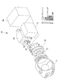
図1及び図2に示す参考例の増速機20は、第1段増速部から第3段増速部まで3段階の増速を行うものである。この増速機20の第1段増速部は、太陽歯車(太陽部)21、遊星歯車(遊星部)22及びリングギヤ(リング部)23を組み合わせてなるスター型増速機構であり、主軸12を支持する主軸受50が外周部に一体に組み合わされた構成とされる。すなわち、太陽歯車21の外周部に配置されて噛合する遊星歯車22は、各々の設置位置で太陽歯車21及びリングギヤ23と噛合して自転するものの、太陽歯車21の周囲を公転することはない。従って、このようなスター型の増速機20の潤滑は、各遊星歯車22に対して適所から潤滑油を供給することで容易に実施することができる。
図示の構成では、主軸12とリングギヤ23とが軸方向に突き合わされ、複数のボルト24により一体に結合されている。リングギヤ23は、外周面が主軸受50に対して、すなわち、内輪部52の内周面52aに圧入して嵌合されている。また、リングギヤ23の内周面には、遊星歯車22と噛合する内歯車23aが形成されている。
The speed increaser 20 of the reference example shown in FIG.1 and FIG.2 performs 3 steps | paragraphs of speed increase from a 1st stage | paragraph speed increase part to a 3rd stage | paragraph speed increase part. The first stage speed increasing portion of the
In the configuration shown in the drawing, the
遊星歯車22は、太陽歯車21の周方向において、複数(たとえば4個)が等ピッチに配置されて互いに噛合している。各遊星歯車22には、歯車の両側面へ突出する回転軸22a,22bが設けられている。両回転軸22a,22bは、それぞれが軸受25を介して前面支持部材26及び後面支持部材27に回転自在に支持されている。このため、遊星歯車22においては、二つの回転軸22a,22bが荷重を分担して負担可能な構造となるので、噛合部における片当たりの原因である荷重による回転軸の傾きを防止し、増速機20の耐久性を増すことができる。なお、この場合の前面はロータヘッド4側であり、後面が発電機14側である。
A plurality of (for example, four) planetary gears 22 are arranged at an equal pitch in the circumferential direction of the
また、軸受25を前面支持部材26及び後面支持部材27に組み付ける際、軸受25の外輪は、通常の隙間ばめではなく、がたつきを生じない冷ばめとされる。さらに、前面支持部材26及び後面支持部材27との間において、遊星歯車22のない空間部分には、両支持部材26,27間を連結するステー28が設置される。このステー28は、たとえば図2に示すように、円周方向に隣接する遊星歯車22の間に、遊星歯車22の回転と干渉しないように設置されている。
このように、遊星歯車22を冷ばめしてがたつきのない軸受25で支持するとともに、ステー28を設けて第1段増速部を補強したことにより、風車翼5を支持するハブ11とともに回転する主軸12に撓みが生じたり、第1段増速部の噛合部が軸方向において片当たりが生じることを防止できるようになり、従って、増速機20の耐久性や信頼性を増すことができる。
Further, when the
In this way, the
太陽歯車21は、周囲に配設された複数の遊星歯車22との噛合により、主軸12と同軸上で回転可能に支持されている。すなわち、増速機20の第1段増速部においては、軸中心位置に配置されて回転する太陽歯車21が周囲に配設された遊星歯車22と噛合し、さらに、遊星歯車22は、外周側に配設されたリングギヤ23と噛合することにより、主軸12と一体に回転するリングギヤ23の回転数が各歯車のギヤ比に応じて増速され、太陽歯車21の出力軸21aから出力される。
The
上述した主軸受50は、本体51と後面支持部材27との間にナセル3のフレーム部材3aを挟持するようにして、各部材を貫通する複数のボルト54を締め付けることにより固定支持されている。従って、主軸受50は、増速機20の外周部を嵌合させて、より具体的には、スター型とした増速機20の第1段増速部と嵌合させて一体化した構成とされる。この結果、主軸20及びリングギヤ23は、ナセル3のフレーム部材3aに支持された固定側の本体51に対し、圧入により嵌合した内輪部52と共に回転する。
The
図示の増速機20は、太陽歯車21の出力軸21aが後面側に配置されているプラネタリ型の第2段増速部と連結されている。
第2段増速部は、太陽歯車30と、複数の遊星歯車31と、リングギヤ32と、出力軸33とを具備して構成される。なお、第2段増速部及び後述する第3段増速部は、一体のケーシング34の内部に収納され、このケーシング34は、上述した後面支持部材27に対して複数のボルト35により固定されている。
The
The second speed increasing portion includes a
太陽歯車30は、一体の入力軸30aが連結部材36を介して第1段増速部の出力軸21aと連結され、前後一対の軸受37及び後述する複数の遊星歯車31との噛合により、回転自在に支持されている。この太陽歯車30は、入力軸30aを軸中心として円周方向へ等ピッチに配置された複数の軸部30bを備えている。この軸部30bには、軸受38を介して遊星歯車31が回転自在に支持されている。
遊星歯車31は、ケーシング34に固定支持されたリングギヤ32の内歯車32a及び出力軸33の外周面に形成された外歯車33aと噛合している。そして、この遊星歯車31は、太陽部材30の回転により旋回する軸部30bと一体に、軸部30bの回りを自転しながら公転することとなる。この結果、出力軸33の回転数は、第2段増速部を構成する各歯車のギア比に応じて出力軸21aと一体に回転する入力軸30a及び太陽歯車30の回転数から増速される。
The
The
上述した第2段増速部により増速された出力軸33は、第3段増速部を構成する大歯車39の内歯車39aと噛合して回転させる。この大歯車39は、前後一対の軸受40により回転自在に支持されている。そして、この大歯車39は、外周面に形成した外歯車39bが図示しない小歯車と噛合している。この小歯車は、高速カップリング13を介して発電機14を駆動する最終出力軸41(図4参照)に取り付けられ、図1において大歯車39の紙面裏側に位置して一体に回転する。
従って、第2段増速部で増速された出力軸33の回転数は、各歯車のギア比に応じて最終出力軸41の回転数まで増速される。すなわち、増速機20においては、第1段増速部から第3段増速部まで主軸12の回転数を3段階にわたって増速し、最終的には最終出力軸41の回転数まで増速して発電機14を駆動する。
The
Therefore, the rotation speed of the
このように、主軸12を支持する主軸受50を第1段増速部の外周に、すなわちリングギヤ23に組み付けて一体化した構成の増速機20は、風力発電装置1のドライブトレイン10を軸方向に短くすることができる。このため、ナセル3の内部に収納設置されるドライブトレイン10は、全体を小型軽量化することができる。また、ドライブトレイン10を収納設置するナセル3についても、特にナセル台板の荷重負担を軽減して小型化できることから、全体を小型軽量化することができる。
Thus, the
次に、上述した参考例について、第1段増速部の第1変形例を図5に示して説明する。なお、以下に説明する変形例は、第2増速部及び第3増速部の構成が上述した参考例と同様であり、従って、その詳細な説明は省略する。なおまた、第1段増速部の構成についても、上述した参考例と同様の部分には同じ符号を付し、その詳細な説明は省略する。
図5は、第1変形例に係る第1段増速部について、要部の構成を示す断面図である。主軸12のフランジ部12aは、主軸受50の本体51に対して複数のボルト24′により固定されている。本体51の外周面には、リングギヤ23の前面側内周面23bが一体に回転するようスプライン等により嵌合されている。また、主軸受50の内輪部52は、内周面52a側に設けた支持部材55により補強されている。なお、この場合の主軸受50は、ボルト56の締め付けに応じてローラ部材53の密着力を調整可能な予圧型軸受とされる。
Next, the above-described reference example will be described with reference to FIG. In the modified example described below, the configurations of the second speed increasing portion and the third speed increasing portion are the same as those of the reference example described above, and therefore detailed description thereof is omitted. In addition, for the configuration of the first stage speed increasing portion, the same reference numerals are given to the same portions as those in the above-described reference example, and detailed description thereof will be omitted.
FIG. 5 is a cross-sectional view showing the configuration of the main part of the first stage speed increasing portion according to the first modification. The
一方、遊星歯車22は、回転軸22cにより回転自在に支持されている。この場合の回転軸22cは、前面側が内輪部52を貫通するボルト56により支持され、かつ、後面側が軸受25により支持されている。そして、遊星歯車22は、外周側においてリングギヤ23の内歯車23aと噛合し、内周側において太陽歯車21と噛合している。なお、太陽歯車21の出力軸21aが第2段増速部と連結される構成については、上述した参考例と同様である。
On the other hand, the
このように構成された第1段増速部は、主軸12の回転により本体51及びリングギヤ23が一体に回転するので、リングギヤ23と噛合する遊星歯車22も回転軸22cに支持されて回転する。さらに、遊星歯車22の回転は、噛合する太陽歯車21を回転させるので、主軸12の回転数は、各歯車のギア比に応じて増速されて出力軸21aから第2段増速部へ伝達される。
そして、上述した構成の第1段増速部は、主軸12を本体51に連結する構成となるため、主軸12と軸方向に突き合わせて結合したリングギヤ23を内輪部52に嵌合した構成と比較すれば、主軸受50の小径化が可能となってコスト面で有利になる。また、上述したリングギヤ23と本体51とを一体に回転させる構造については、特に限定されるものではないが、主軸12の調芯機能を有することからスプライン結合が望ましい。
In the first-stage speed increasing portion configured as described above, the
The first-stage speed increasing portion having the above-described configuration is configured to connect the
図6に示す第2変形例では、主軸12のフランジ部12aが予圧型とした主軸受50の内輪部52に連結されるとともに、内輪部52の内周面には、リングギヤ23の内歯車23aに相当する内歯車52bが形成されている。この内歯車52bは、遊星歯車22と噛合している。すなわち、この変形例では、リングギヤ23が主軸受50と一体化された構成とされ、この結果、部品点数の低減が可能になる。また、軸方向の長さについても、上述した実施形態と比較して短縮することができる。
なお、図中の符号22dは遊星歯車22と一体の回転軸、56は主軸12のフランジ部を固定するボルトである。
In the second modification shown in FIG. 6, the
In the figure,
図7に示す第3変形例では、上述した第2変形例と同様に、主軸12のフランジ部12aが予圧型とした主軸受50の内輪部52に連結されている。そして、内輪部52の後面側には、内輪部52を貫通させた主軸固定用のボルト56を用いて、リングギヤ23のフランジ部23bが固定されている。この場合、主軸12及びリングギヤ23に形成したフランジ部12a,23bが軸中心側へ延在しているので、これらのフランジ部12a,23bを内輪部52の両側面に固定することで、上述した第2変形例と比較して主軸受50を小径化することができる。
In the third modification shown in FIG. 7, the
図8に示す本発明の一実施形態では、軸方向に二分割した主軸受50Aの間にリングギヤ23を挟持した構成とされる。なお、図8は、図1に示す増速機の内部構成について、第1段増速部を示す要部断面図である。
主軸受50Aは、本体51及び内輪部52が軸方向に二分割されており、前面側の内輪部52には主軸12のフランジ部12aがボルト56により固定されている。このようにして主軸12が固定された前面側の内輪部52は、後面側の内輪部52との間にリングギヤ23を挟持し、両方向からボルト56,56′を締め込んで一体化される。この結果、軸方向に前後一対配置されているローラ部材53間の間隔は、略内輪部52の間に挟持した遊星歯車22の幅分だけ広がることとなる。従って、主軸受50Aにおいては、主軸12の回転により作用するモーメントに対して耐性が向上する。
In the embodiment of the present invention shown in FIG. 8, the
In the
図9に示す本実施形態の変形例では、上述した実施形態と同様に、軸方向に二分割した主軸受50Bの間にリングギヤ23を挟持した構成とされるが、主軸12の固定位置及びリングギヤ23の挟持位置が異なっている。
すなわち、本体51及び内輪部52が軸方向に二分割された主軸受50Bに対し、前面側の本体51に主軸12のフランジ部12aがボルト56により固定されている。このようにして主軸12が固定された前面側の本体51は、後面側の本体51との間にリングギヤ23を挟持して図示省略のボルト等により固定して一体化される。この結果、軸方向に前後一対配置されているローラ部材53間の間隔は、略本体51間に挟持した遊星歯車22の幅分だけ広がることとなる。従って、主軸受50Bにおいては、主軸12の回転により作用するモーメントに対して耐性が向上する。
In the modification of the present embodiment shown in FIG. 9, the
That is, the
さらに、この変形例によれば、リングギヤ23が本体51の間に挟持されているので、主軸受50Bの径を上述した実施形態より小さくすることができ、従って、主軸受50Bのコスト低減が可能となる。
なお、図中の符号22eは遊星歯車22の回転軸、25Aは遊星歯車22を回転自在に支持する軸受である。
Furthermore, according to this modification, since the
In the figure,
<他の参考例>
続いて、上述した増速機20の第1段増速部について、歯車に代えてトラクションドライブを採用した他の参考例を図10に基づいて説明する。この場合においても、第2増速部及び第3増速部の構成は上述した実施形態または参考例(各変形例を含む)と同様である。なお、第1段増速部の構成について、上述した実施形態及び参考例と同様の部分には同じ符号を付し、その詳細な説明は省略する。
図10に示す参考例においては、上述した太陽歯車21、遊星歯車22及びリングギヤ23に代えて、密着面に生じるトラクションにより動力(トルク)の伝達を行うトラクションドライブ部材の太陽ローラ(太陽部)61、遊星ローラ(遊星部)62及びリングローラ(リング部)63が採用されている。
<Other reference examples>
Next, another reference example in which a traction drive is used instead of the gears for the first speed increasing portion of the
In the reference example shown in FIG. 10, instead of the
主軸12は、主軸受70の前面側に複数のボルト71を用いて固定されている。この主軸受70は、内周面側に一体化されたリングローラ63を備えている。
遊星ローラ62は、太陽ローラ61とリングローラ63との間に、周方向へ等ピッチに複数(たとえば3〜4個)設置されている。これらの遊星ローラ62は、ローラ本体62aにボルト62bで固定された回転軸62cが軸受25に回転自在に支持されている。すなわち、各遊星ローラ62は、軸受25により支持された回転軸62cを軸中心として、所定の位置で自転することとなる。
The
A plurality (for example, 3 to 4) of
太陽ローラ61は、前述した太陽歯車21と同様に、周囲に配設された複数の遊星ローラ62と密着することにより、主軸12と同軸上を回転可能に支持されている。すなわち、増速機20の第1段増速部においては、軸中心位置に配置されて回転する太陽ローラ61が周囲に配設された複数の遊星ローラ62と密着してトラクションを生じ、さらに、遊星ローラ62は、外周側に配設されたリングローラ63と密着してトラクションを生じることにより、主軸12と一体に回転するリングローラ63の回転数が各ローラの直径比に応じて増速され、太陽ローラ61の出力軸61aから出力される。
Similar to the
このような構成とすれば、回転数の増速にトラクションドライブを採用することにより、第1段増速部が増速機能と主軸受の機能とを備えた構成となるので、部品点数の低減とともに小型軽量化が可能となる。また、トラクションドライブを採用して増速する構成としたことにより、歯車を採用した増速機と比較して運転時の騒音を低減することができる。 By adopting such a configuration, by adopting a traction drive to increase the rotational speed, the first stage speed increasing portion has a speed increasing function and a function of the main bearing, so that the number of parts can be reduced. At the same time, it is possible to reduce the size and weight. Further, by adopting a configuration in which the traction drive is used to increase the speed, noise during operation can be reduced as compared with a speed increaser that uses a gear.
ところで、上述したトラクションドライブを用いた第1段増速部の構成は、以下に説明する変形例が可能である。なお、以下に説明する変形例は、第2増速部及び第3増速部の構成が上述した参考例と同様であり、従って、その詳細な説明は省略する。なおまた、第1段増速部の構成についても、上述した参考例と同様の部分には同じ符号を付し、その詳細な説明は省略する。
図11に示す第1変形例は、歯車を用いた第1段変速部の第2変形例(図6参照)をトラクションドライブに変更したものである。すなわち、主軸12のフランジ部12aが主軸受50の内輪部52に連結されるとともに、内輪部52の内周面には、リングギヤの内歯車に代えてリングローラ63Aが形成されている。このリングローラ63Aは、遊星ローラ62とトラクション面同士が密着しているので、リングローラ63Aが主軸受50と一体化された構成とされる。
By the way, the structure of the 1st stage speed increasing part using the traction drive mentioned above can be modified as described below. In the modified example described below, the configurations of the second speed increasing portion and the third speed increasing portion are the same as those of the reference example described above, and therefore detailed description thereof is omitted. In addition, for the configuration of the first stage speed increasing portion, the same reference numerals are given to the same portions as those in the above-described reference example, and detailed description thereof will be omitted.
The first modification shown in FIG. 11 is obtained by changing the second modification (see FIG. 6) of the first speed change unit using gears to a traction drive. That is, the
また、太陽ローラ61Aと遊星ローラ62Aとの間もトラクション面同士が密着しているので、リングローラ63Aと遊星ローラ62Aとの密着面や遊星ローラ62Aと太陽ローラ61Aの密着面にはトラクションが生じ、トルク伝達とともに各ローラの直径比に応じた増速が行われる。なお、図中の符号62dは遊星ローラ62Aの回転軸、61aは太陽ローラ61Aの回転軸である。
このような構成を採用しても、第1段増速部の構成部品点数を低減することができ、さらに、軸方向の長さについても短縮することができる。
Also, since the traction surfaces are in close contact with each other between the
Even if such a configuration is adopted, the number of component parts of the first stage speed increasing portion can be reduced, and the axial length can also be shortened.
図12に示す第2変形例は、主軸受50Cを略コ字形の断面形状とし、一体化したリングローラ63Aのトラクション面をボルト64の締め付けにより凸状に撓ませるものである。すなわち、トラクション面から略垂直に立ち上がる一対の対向部57を軸受50Cに形成しておき、この対向部57及び主軸12のフランジ部12aを貫通するボルト64により主軸12を固定するが、このとき、ボルト64の締付力を調整することで、トラクション面は遊星リング62A側へ膨出するように撓む。従って、この撓み量を調整すれば、各リングのトラクション面間に生じる密着力を増し、トラクションによるトルクの伝達効率を向上させることができる。
In the second modification shown in FIG. 12, the
このように、本発明の風力発電装置によれば、増速機20の軸方向を短くして小型軽量化が達成されるので、ドライブトレイン全体についても軸方向長さを短くして軽量化が可能になる。従って、ドライブトレイン自体のコスト低減が可能になるとともに、大出力化に伴って大型化する傾向にある風力発電装置の支柱上部荷重を低減することができる。このような支柱上部荷重の低減は、支柱や基礎等の負担を軽減するだけでなく、ドライブトレインを収納設置するナセル等の現地据付作業を容易にするので、この点からも風力発電装置のコスト低減が可能になる。
なお、本発明は上述した実施形態に限定されることはなく、その要旨を逸脱しない範囲内において適宜変更することができる。
Thus, according to the wind turbine generator of the present invention, the axial direction of the
In addition, this invention is not limited to embodiment mentioned above, In the range which does not deviate from the summary, it can change suitably.
1 風力発電装置
2 支柱
3 ナセル
4 ロータヘッド
5 風車翼
10 ドライブトレイン
11 ハブ
12 主軸
14 発電機
20 増速機
21 太陽歯車(太陽部)
22 遊星歯車(遊星部)
23 リングギヤ(リング部)
41 最終出力軸
50,50A,50B,50C 主軸受
61,61A 太陽ローラ(太陽部)
62,62A 遊星ローラ(遊星部)
63,63A リングローラ(リング部)
DESCRIPTION OF SYMBOLS 1
22 Planetary gear (planetary part)
23 Ring gear (ring part)
41
62,62A Planetary roller (planetary part)
63, 63A Ring roller (ring part)
Claims (2)
前記ロータヘッドから前記発電機まで回転力を伝達するドライブトレインの増速機が、第1段増速部に主軸受と一体のスター型増速機構を備え、
前記主軸受は、前記スター型増速機構のリング部材と一体化され、
前記リング部材は、前記主軸受を軸方向に二分割した軸受間に挟持されていることを特徴とする風力発電装置。 A wind turbine generator that generates power by driving a generator connected via a drive train and a rotor head to which a wind turbine rotor blade is attached and rotates integrally,
A drive train speed increaser that transmits rotational force from the rotor head to the generator includes a star-type speed increasing mechanism integrated with a main bearing in a first speed increasing portion ,
The main bearing is integrated with a ring member of the star-type speed increasing mechanism,
The wind power generator , wherein the ring member is sandwiched between bearings obtained by dividing the main bearing into two in the axial direction .
Priority Applications (1)
| Application Number | Priority Date | Filing Date | Title |
|---|---|---|---|
| JP2008102754A JP5148346B2 (en) | 2008-04-10 | 2008-04-10 | Wind power generator |
Applications Claiming Priority (1)
| Application Number | Priority Date | Filing Date | Title |
|---|---|---|---|
| JP2008102754A JP5148346B2 (en) | 2008-04-10 | 2008-04-10 | Wind power generator |
Publications (2)
| Publication Number | Publication Date |
|---|---|
| JP2009250213A JP2009250213A (en) | 2009-10-29 |
| JP5148346B2 true JP5148346B2 (en) | 2013-02-20 |
Family
ID=41311151
Family Applications (1)
| Application Number | Title | Priority Date | Filing Date |
|---|---|---|---|
| JP2008102754A Expired - Fee Related JP5148346B2 (en) | 2008-04-10 | 2008-04-10 | Wind power generator |
Country Status (1)
| Country | Link |
|---|---|
| JP (1) | JP5148346B2 (en) |
Cited By (1)
| Publication number | Priority date | Publication date | Assignee | Title |
|---|---|---|---|---|
| KR102213828B1 (en) | 2020-11-17 | 2021-02-09 | 한창기술 주식회사 | Automatic expansion device with detonating circuit |
Families Citing this family (6)
| Publication number | Priority date | Publication date | Assignee | Title |
|---|---|---|---|---|
| KR101161484B1 (en) | 2010-02-12 | 2012-07-02 | 미츠비시 쥬고교 가부시키가이샤 | Gear box for wind turbine generator and wind turbine generator |
| JP5161958B2 (en) * | 2010-02-12 | 2013-03-13 | 三菱重工業株式会社 | Speed increaser for wind power generator and wind power generator |
| EP2508754B1 (en) * | 2011-04-04 | 2016-03-30 | Siemens Aktiengesellschaft | Drive system for a wind turbine |
| WO2014012947A1 (en) * | 2012-07-16 | 2014-01-23 | Colipu A/S | A wind turbine gearbox |
| CN102979857A (en) * | 2012-11-17 | 2013-03-20 | 吴小杰 | Bearing-grease lubricating wind-power double-cycloidal variable-pitch speed reducer |
| JP2015169143A (en) * | 2014-03-07 | 2015-09-28 | 株式会社ジェイテクト | Power generation device and shaft coupling device used in the same |
Family Cites Families (2)
| Publication number | Priority date | Publication date | Assignee | Title |
|---|---|---|---|---|
| WO2002014690A1 (en) * | 2000-08-15 | 2002-02-21 | Hansen Transmissions International Nv | Drive assembly for wind turbines |
| DE102006057055B3 (en) * | 2006-12-04 | 2008-06-19 | Lohmann & Stolterfoht Gmbh | Power-split wind turbine gearbox |
-
2008
- 2008-04-10 JP JP2008102754A patent/JP5148346B2/en not_active Expired - Fee Related
Cited By (1)
| Publication number | Priority date | Publication date | Assignee | Title |
|---|---|---|---|---|
| KR102213828B1 (en) | 2020-11-17 | 2021-02-09 | 한창기술 주식회사 | Automatic expansion device with detonating circuit |
Also Published As
| Publication number | Publication date |
|---|---|
| JP2009250213A (en) | 2009-10-29 |
Similar Documents
| Publication | Publication Date | Title |
|---|---|---|
| WO2011027427A1 (en) | Wind driven generator | |
| CA2669276C (en) | Wind turbine generator | |
| CA2531278C (en) | Wind turbine generator | |
| JP4031747B2 (en) | Wind turbine for wind power generation | |
| JP5148346B2 (en) | Wind power generator | |
| US20100219642A1 (en) | Wind turbine with single main bearing | |
| US20090289460A1 (en) | Wind Turbine With A Drive Train | |
| US9297364B2 (en) | Bogie plate for wind turbine | |
| CN102588226B (en) | For the power train of the generator in wind turbine | |
| CN101836014A (en) | A gearbox for a wind turbine, a method of converting wind energy and use of a gearbox | |
| AU2008252039A1 (en) | Wind turbine drive | |
| US9028361B2 (en) | Modular gear unit for a wind turbine | |
| US11466669B2 (en) | Drive train arrangement | |
| JP5287631B2 (en) | Wind power generator | |
| JP4909578B2 (en) | Windmill drive | |
| KR101074694B1 (en) | Wind turbine gearbox with rotating housing | |
| JP2006249982A (en) | Wind power generator | |
| WO2004013516A1 (en) | Gear transmission unit with planet carrier | |
| AU2011226784B2 (en) | Wind power generator |
Legal Events
| Date | Code | Title | Description |
|---|---|---|---|
| A621 | Written request for application examination |
Free format text: JAPANESE INTERMEDIATE CODE: A621 Effective date: 20101227 |
|
| A977 | Report on retrieval |
Free format text: JAPANESE INTERMEDIATE CODE: A971007 Effective date: 20120518 |
|
| A131 | Notification of reasons for refusal |
Free format text: JAPANESE INTERMEDIATE CODE: A131 Effective date: 20120522 |
|
| A521 | Request for written amendment filed |
Free format text: JAPANESE INTERMEDIATE CODE: A523 Effective date: 20120723 |
|
| A131 | Notification of reasons for refusal |
Free format text: JAPANESE INTERMEDIATE CODE: A131 Effective date: 20120814 |
|
| A521 | Request for written amendment filed |
Free format text: JAPANESE INTERMEDIATE CODE: A523 Effective date: 20121011 |
|
| TRDD | Decision of grant or rejection written | ||
| A01 | Written decision to grant a patent or to grant a registration (utility model) |
Free format text: JAPANESE INTERMEDIATE CODE: A01 Effective date: 20121106 |
|
| A61 | First payment of annual fees (during grant procedure) |
Free format text: JAPANESE INTERMEDIATE CODE: A61 Effective date: 20121128 |
|
| R151 | Written notification of patent or utility model registration |
Ref document number: 5148346 Country of ref document: JP Free format text: JAPANESE INTERMEDIATE CODE: R151 |
|
| FPAY | Renewal fee payment (event date is renewal date of database) |
Free format text: PAYMENT UNTIL: 20151207 Year of fee payment: 3 |
|
| LAPS | Cancellation because of no payment of annual fees |