JP5114930B2 - Mass spectrometer ion source - Google Patents
Mass spectrometer ion source Download PDFInfo
- Publication number
- JP5114930B2 JP5114930B2 JP2006323439A JP2006323439A JP5114930B2 JP 5114930 B2 JP5114930 B2 JP 5114930B2 JP 2006323439 A JP2006323439 A JP 2006323439A JP 2006323439 A JP2006323439 A JP 2006323439A JP 5114930 B2 JP5114930 B2 JP 5114930B2
- Authority
- JP
- Japan
- Prior art keywords
- ionization chamber
- heat
- sample
- source
- plate
- Prior art date
- Legal status (The legal status is an assumption and is not a legal conclusion. Google has not performed a legal analysis and makes no representation as to the accuracy of the status listed.)
- Active
Links
Images


Landscapes
- Other Investigation Or Analysis Of Materials By Electrical Means (AREA)
- Electron Tubes For Measurement (AREA)
Description
ガス状サンプルを導入してイオン化する質量分析計におけるイオン源のイオン化部の加熱に関する。 The present invention relates to heating of an ionization section of an ion source in a mass spectrometer that introduces a gaseous sample and performs ionization.
本発明は、サンプル化合物分子の質量を測定する質量分析計たとえば、ガスクロマトグラフ質量分析計(以下GC/MSと称する)におけるイオン源について説明する。 The present invention describes an ion source in a mass spectrometer that measures the mass of sample compound molecules, such as a gas chromatograph mass spectrometer (hereinafter referred to as GC / MS).
GC/MSでは、分析するサンプルを気化した状態で装置に導入しイオン化しイオンの分離および測定を行うが、サンプルがとくに高沸点化合物の場合温度低下の起こった場所に吸着し分析感度の低下が生じる。 In GC / MS, the sample to be analyzed is introduced into the apparatus in a vaporized state, ionized, and ions are separated and measured. However, if the sample is a high boiling point compound, it is adsorbed at the location where the temperature has dropped and the analytical sensitivity is reduced. Arise.
GC/MSの構成部品のひとつであるイオン源においても同様の影響があるためイオン化室内の壁への付着を防止する手段として、イオン源のイオン化室は加熱し保温される。通常イオン化室を加熱し保温するためにイオン源に機能上必要とされるサンプルガス分子をイオン化するための電子線を放射するフィラメントおよびリペラー電極、収束レンズ、マグネットを避けて熱源を配置する(特許文献1参照)。 Since the ion source which is one of the components of the GC / MS has the same influence, the ionization chamber of the ion source is heated and kept warm as a means for preventing adhesion to the walls in the ionization chamber. In order to heat and keep the ionization chamber normally, the heat source is arranged avoiding the filament, repeller electrode, converging lens, and magnet that emit electron beams to ionize the sample gas molecules that are functionally required for the ion source (patented) Reference 1).
図5、図6および図7はGC/MSのイオン源の構造を示している。図5はイオン源の正面図を示す。図6は図5の矢線I−Iにおける断面図を示す。図7は図5の平面図を示す。 5, 6 and 7 show the structure of the GC / MS ion source. FIG. 5 shows a front view of the ion source. 6 shows a cross-sectional view taken along the line II in FIG. FIG. 7 shows a plan view of FIG.
図5で、15は熱源でヒータ2と温度センサー3とヒートブロック1(図6、7に示す)で構成され、9aはリペラー電極リード端子で10はフィラメントリード端子、10aはフィラメント取付けネジであり、26はプレートで熱源15とリペラー電極9とイオン化室箱8(図6に示す)を取付けるためのプレートを兼ねており、これらの部品はイオン源を構成する部品の一部である。13はサンプル導入部である。熱源15によりイオン化室箱8は加熱され、GCからのサンプルガスはサンプル導入部13を通してイオン化室箱8内に導入される。
In FIG. 5, 15 is a heat source, which is composed of a
図6で、イオン化室箱8に設けられた電子入射孔17を通してイオン化室Aにイオン化室箱8の外部に配置されたフィラメント(図示せず)から放射された電子を紙面に垂直方向に入射させ、サンプル導入部13を介してイオン化室箱8に接続されたガスクロマトグラフのカラム28によりサンプル導入孔19を通してイオン化室Aに導入されたサンプルガス分子をイオン化する。前記フィラメントは2個設けられている場合があり一方が作動しているときは他方は電子トラップとして機能する。イオン化室Aで生成されたサンプルイオンは、リペラー電極9によりイオン化室箱8に設けられたイオン出射孔18よりレンズ電極11、11aが形成する電界レンズ空間Cに押し出され収束されてイオンビーム29は真空チャンバーB内に設けられた質量分離部に導入され質量分離されイオン信号として検出される。なお、11bはレンズ電極11、11aを固定するための位置決めピンである。20はプレート26によりイオン化室箱8とリペラー電極9をイオン化室プレート23に締結固定するためのボルトであり、20aはイオン化室プレート23に設けられたボルト20を止めるタップ穴である。
In FIG. 6, electrons radiated from a filament (not shown) arranged outside the
図7では図5で説明したように、熱源15はヒートブロック1とそれに埋設したヒータ2と温度センサー3で構成され、イオン化室プレート23に固着している。熱源15からの熱はイオン化室箱8を載架しているイオン化室プレート23を通じてイオン化室箱8に伝導され、イオン化室Aが所定温度に保持されるようになっている。24はスペーサでフィラメント(図示せず)とマグネット21の保持とイオン化室箱8とイオン化室プレート23の固定を兼ねており、12はイオン源のベース板である。マグネット21はイオン化室箱8の外側に配置したフィラメント(図示せず)の後方に配置されておりフィラメントから放射される電子流をイオン化室A内で集光してサンプルガスと電子線の衝突断面積を大きくしイオン化効率を高める働きをする。
In FIG. 7, as described with reference to FIG. 5, the
しかし、上述した従来のイオン源では熱源15の配置およびイオン化室箱8に接触して熱を伝導するイオン化室プレート23の材料と、イオン化室プレート23を支持するスペーサ24の材料によりまたそれらの配置や構成により、イオン化室箱8とイオン化室Aの加熱および保温の効率性が問題である。また装置を停止してメンテナンスを行う場合は、高温での大気暴露による部品材料表面の劣化をさけるために真空中でイオン源の温度を下げる必要があるが、真空中であるため前記部品の材料と配置や構成によりメンテナンス可能な温度である約40度以下に低下するまでに長時間を要する問題もある。
熱源15は、熱源が接触しているイオン化室プレート23を通じてイオン化室箱8を加熱、保温するが位置的な制約があり、図5、図7のようにサンプル導入部13の反対側に熱源15を配置することになる。この構成では熱源15から発生した熱は、イオン化室プレート23、スペーサ24、ベース板12を通って真空チャンバーBに逃げる。この場合、熱源15からイオン化室プレート23およびスペーサ24に向かって熱の移動がありサンプル導入部13側に向かって熱勾配が発生する。図6で熱源15から遠いサンプル導入部13側のイオン化室箱8の温度が低下しサンプル導入孔19側のイオン化室箱8の内壁およびサンプル導入孔19の内壁に高沸点成分サンプルの吸着が起こり分析感度の低下を引き起こす。温度低下分を補うように設定温度を上昇させることが対策として考えられるが、熱が逃げるためイオン化室箱8の内壁の温度が均一にならずに温度差が発生し必要以上に高温の部分ができる。そのため化合物によっては内壁に接触して分解し正確な分析ができない。
The
従って、熱源15からイオン源に伝導される熱の損失を減らして、サンプルが接触する部分は温度差を少なくし、均一に保持することができない問題がある。また、装置を停止してメンテナンスを行う場合はイオン源の温度を下げなければならないが、真空雰囲気ではメンテナンスが可能な温度に低下するまで長時間を要するため温度低下時間を短縮する必要がある。
Therefore, there is a problem that the loss of heat conducted from the
特許文献1に示す技術では、図5の破線で示すようにインタフェースブロック14がイオン化室箱8に当接するようにした構造になっており、サンプルガス分子はインタフェースブロック14の中心線を貫通したサンプル導入流路よりイオン化室に導入される。インタフェースブロック14を熱源として利用しイオン化室箱を加熱していたがイオン化室の加熱、保温が効率良く行えない問題とイオン化室箱をインタフェースブロック14に対して独立して加熱、保温ができない問題がある。
In the technique shown in
本発明は、従来の質量分析計のイオン源部の加熱、保温および放熱に関する上述のような問題点を解消するイオン源を提供しようとするものである。 The present invention seeks to provide an ion source that solves the above-described problems associated with heating, heat retention and heat dissipation of an ion source of a conventional mass spectrometer.
本発明が提供するイオン源は、上記課題を解決するために、加熱源をサンプル導入部と反対側に配置しまたはイオン化室箱を包囲するように配置し、イオン化室箱と加熱源を直接載架するイオン化室プレートをサンプル導入部に近い側は断熱体で支持しあるいは支持せずに、サンプル導入部から遠い側は放熱体で支持する構成とする。この構成により適正な加熱が保証される。 In order to solve the above problems, the ion source provided by the present invention is arranged such that the heating source is arranged on the side opposite to the sample introduction part or surrounding the ionization chamber box, and the ionization chamber box and the heating source are directly mounted. The ionization chamber plate is constructed so that the side near the sample introduction part is supported or not supported by a heat insulator, and the side far from the sample introduction part is supported by a heat radiator. This configuration ensures proper heating.
本発明によれば、加熱源からのイオン化室箱への熱伝導が効率良く行えるためイオン化室内の温度分布が熱源に近い温度で均一に保持され、高沸点化合物サンプルがイオン化室箱のサンプル導入孔側のイオン化室壁およびサンプル導入孔部分に吸着するのを抑えることができる。また、イオン化室の内壁が必要以上に加熱されることもなくサンプルの分解も起こらず分析感度が向上する。熱源側を放熱性のある部材で固定しているので、装置を停止してメンテナンスを行う場合などはイオン源の冷却時間を短縮することができ、迅速にメンテナンスを行うことができる。 According to the present invention, the heat distribution from the heating source to the ionization chamber box can be efficiently performed, so that the temperature distribution in the ionization chamber is uniformly maintained at a temperature close to the heat source, and the high-boiling compound sample is sampled in the ionization chamber box Adsorption to the side ionization chamber wall and the sample introduction hole portion can be suppressed. In addition, the inner wall of the ionization chamber is not heated more than necessary, the sample is not decomposed, and the analysis sensitivity is improved. Since the heat source side is fixed with a heat radiating member, when the apparatus is stopped and maintenance is performed, the cooling time of the ion source can be shortened, and the maintenance can be performed quickly.
サンプル導入部側の固定を断熱性の高い材料を用いて放熱の少ない構造とすることでこの熱流量の損失を減少させることができる。また、イオン化室プレートの熱伝導性が増加するように材料および構造を決めることで単位熱流量に対する温度低下量を減少できる。 The loss on the heat flow rate can be reduced by fixing the sample introduction part side to a structure with less heat dissipation using a material having high heat insulation. Further, by determining the material and structure so that the thermal conductivity of the ionization chamber plate is increased, the amount of temperature decrease with respect to the unit heat flow rate can be reduced.
さらに本発明はサンプル導入部以外の部位でイオン化室プレートを固定するものである。この構成によりさらに熱損失を減少させる。 Furthermore, the present invention fixes the ionization chamber plate at a site other than the sample introduction part. This configuration further reduces heat loss.
サンプル導入部側に支持点を設けないことによって、サンプル導入部側への熱流を無くしているため請求項1よりも熱損失が少ない。また、イオン化室プレートの熱伝導率が増加するように材料および構造を決めることで単位熱流量に対する温度低下量をさらに減少させることができる。その結果、サンプル導入部側のイオン化室の温度がより熱源に近い温度になりイオン化室壁の温度分布が改善される。 By not providing a support point on the sample introduction part side, the heat flow to the sample introduction part side is eliminated, so that there is less heat loss than in the first aspect. Further, by determining the material and structure so that the thermal conductivity of the ionization chamber plate is increased, the amount of temperature decrease with respect to the unit heat flow rate can be further reduced. As a result, the temperature of the ionization chamber on the sample introduction portion side becomes closer to the heat source, and the temperature distribution of the ionization chamber wall is improved.
本発明はさらに熱源の形状を、イオン化室箱を包囲する形として構成する。すなわちイオン化室プレートの支持位置をイオン化室の温度低下に影響を与えない熱源の外側の位置とし、イオン化室箱に接触する部分のイオン化室プレートの温度勾配発生を防止し、イオン化室の温度低下を生じさせないようにする。イオン化室箱が熱源にて包囲された形となり、この状態で熱源の温度調整を行うと、真空チャンバーにつながる支持部分に向かって熱流が発生することになるが、イオン化室箱自体には放熱経路が設けられておらず真空チャンバーに向かっては熱流が発生せず、温度低下も発生しない。 In the present invention, the shape of the heat source is further configured to surround the ionization chamber box. In other words, the support position of the ionization chamber plate is set to a position outside the heat source that does not affect the temperature decrease of the ionization chamber, and the temperature gradient of the ionization chamber plate in the part in contact with the ionization chamber box is prevented, thereby reducing the temperature of the ionization chamber. Don't make it happen. When the ionization chamber box is surrounded by a heat source and the temperature of the heat source is adjusted in this state, a heat flow is generated toward the support part connected to the vacuum chamber, but the ionization chamber box itself has a heat dissipation path. Is not provided, no heat flow is generated toward the vacuum chamber, and no temperature drop occurs.
以下本発明を実施例にしたがって説明する。
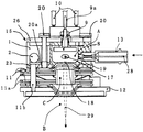
図1と図2および図3は本発明の第1の実施例を示す。図1はイオン源の正面図であり図2は矢線I−Iにおける断面図、そして図3は平面図を示している。図2に示すようにイオン化室箱8およびプレート26、フィラメント(図示せず)、リペラー電極9、レンズ電極11、11aの構造および配置は従来技術と同等である。なお、図1から図4において図5から図7に示す符号と同一の符号で示す部品は図5から図7における部品と同一であり、これらについての詳細な説明は省略する。
The present invention will be described below with reference to examples.
1, 2 and 3 show a first embodiment of the present invention. FIG. 1 is a front view of an ion source, FIG. 2 is a cross-sectional view taken along line I-I, and FIG. 3 is a plan view. As shown in FIG. 2, the structure and arrangement of the
図1で、熱源15はヒータ2と温度センサー3とヒートブロック1から構成されており、熱源15のヒートブロック1が別途の温度制御手段によって一定温度に保たれると、ヒートブロック1に固着しているイオン化室プレート上4とイオン化室プレート下5(図2に示す)が熱源15に近い温度まで加熱される。
In FIG. 1, the
図2に示すようにイオン化室プレート上4はイオン化室箱8の低部の近い側に接触しておりイオン化室プレート下5はイオン化室プレート上4の下側に接触して固定されており、イオン化室プレート上4を熱伝導率の高い材料、例えばアルミ合金、銅合金などで構成し、熱源15からの熱がイオン化室プレート上4を通して効率良くイオン化室箱8に伝わるようにしている。イオン化室プレート下5は熱伝導率がより低い素材、例えばステンレスなどで構成しているが、これは、図2に示すように下側のイオン化室プレート下5にプレート26によりイオン化室箱8とリペラー電極9をボルト20で締結固定するためのタップ穴20aを設け、アルミ合金などにタップ穴を設けると繰り返し締結に耐えられず、下側のプレートを別素材とするためである。なお、27はリペラー電極9を位置決めするためのプレートである。
As shown in FIG. 2, the upper
温度の低下量を最少とするだけであれば、イオン化室プレート上4とイオン化室プレート下5は熱伝導率の高い素材で一体の構成にすることが望ましい。イオン化室プレート上4とイオン化室プレート下5を位置決めし保持する図3のサンプル導入部13側のスペーサ6は、伝熱量が少なくなるような断面形状と長さにして、後述のスペーサ7に比べて放熱量を減少させている。スペーサ7はフィラメント(図示せず)とマグネット21の保持とイオン化室プレート上4とイオン化室プレート下5の固定を兼ねており、イオン化室プレート上4との接触面積は、放熱量を増やすため機能上問題のない範囲で最大となっている。
If the amount of decrease in temperature is to be minimized, it is desirable that the upper
接触面積を多くするのは、熱源15の温度調整を切った後、冷却が短時間で終了することを目的としており、この接触部分を通じての放熱量は、先述のスペーサ6を通じた放熱量に比べて大きくなる。しかし、この熱流は放熱流路が設けられていないイオン化室箱8近辺を通過することはなく直接真空チャンバーBに行くので、イオン化室Aの温度低下を起こすことはない。また、ヒータ2は発熱量がスペーサ7を通した放熱量に対して十分な余裕があるものを使う。なお、図2、図3に示すようにイオン化室箱8およびフィラメント(図示せず)、リペラー電極9、レンズ電極11、11a、マグネット21はその固定位置も重要な要素であり、相互の位置決めができるようベース板12に固定されている。
The purpose of increasing the contact area is to finish the cooling in a short time after the temperature adjustment of the
これらの部品を保持しているイオン化室プレート下5とスペーサ7は、嵌合構造でベース板12に固定されている。
The lower
図4は本発明の実施例2を示す。図4は実施例1の正面図である図3に対応する正面図である。 FIG. 4 shows a second embodiment of the present invention. 4 is a front view corresponding to FIG. 3 which is a front view of the first embodiment.
この実施例2と実施例1との差は、図4に示すようにサンプル導入部13側の支持は行わない点にある。すなわち、実施例1の図3におけるスペーサ6を無くした構成である。これによって、イオン化室箱8周辺のイオン化室プレート上4、イオン化室プレート下5を通って逃げる熱量は微量となり、イオン化室プレート上4自体の熱伝導性は問題とならない程度となるので、熱伝導性よりも強度を確保できる素材、例えばステンレスなどで構成することができる。
The difference between the second embodiment and the first embodiment is that the support on the
従って、実施例1では、図2と図3ようにイオン化室プレート上4およびイオン化室プレート下5の2枚重ねの構造としていたが、本実施例2では図4のように1枚構造のイオン化室プレート25にすることができる。
Accordingly, in the first embodiment, the structure is such that the ionization chamber plate upper 4 and the ionization chamber plate lower 5 are stacked as shown in FIGS. 2 and 3, but in the second embodiment, the single ionization structure is used as shown in FIG. The
実施例3は、上記した実施例1における構成においてイオン化室箱8全体を加熱する構造としたものである。イオン化プレート上4およびイオン化室プレート下5を支持する点は、熱源15と同位置または、熱源15よりも外側に配置する。実施例2と同様にサンプル導入部13側の支持は行わない。熱源15は、実施例1でいうところのスペーサ7と一体構造として、イオン化室箱8のサンプル導入部13側まで熱伝導させる。
The third embodiment has a structure in which the entire
これによって、イオン化室箱8周辺のイオン化室プレート上4とイオン化室プレート下5を通って逃げる熱量はごくわずかとなり、イオン化室プレート自体の熱伝導性は問題とならない程度となるので、熱伝導性よりも、強度を確保できる素材、例えばステンレスなどで構成することができる。従って、この実施例の場合も、イオン化室プレート上4およびイオン化室プレート下5は実施例2と同様1枚構造とすることができる。
As a result, the amount of heat escaping through the upper
本発明は、ガス状サンプルを導入してイオン化する質量分析計のサンプルイオン化部の加熱および保温に関するものであり、またイオン源の冷却時間に関するものでありガスクロマトグラフ質量分析計などに利用可能である。なお、上記実施例においては熱伝導率がより低い材料としてステンレスを例に挙げたが、このステンレス材に限定されるものではなく使用条件が合えば他の材料を利用できる。 The present invention relates to heating and heat retention of a sample ionization part of a mass spectrometer that ionizes by introducing a gaseous sample, and also relates to a cooling time of an ion source and can be used for a gas chromatograph mass spectrometer or the like. . In the above embodiment, stainless steel is taken as an example of a material having a lower thermal conductivity. However, the material is not limited to this stainless material, and other materials can be used as long as the use conditions are met.
1 ヒートブロック
2 ヒータ
3 温度センサー
4 イオン化室プレート上
5 イオン化室プレート下
6 スペーサ
7 スペーサ
8 イオン化室箱
9 リペラー電極
9a リペラー電極リード端子
10 フィラメントリード端子
10a フィラメント取付けネジ
11 レンズ電極
11a レンズ電極
11b 位置決めピン
12 ベース板
13 サンプル導入部
14 インタフェースブロック
15 熱源
17 電子入射孔
18 イオン出射孔
19 サンプル導入孔
20 ボルト
20a タップ穴
21 マグネット
23 イオン化室プレート
24 スペーサ
25 イオン化室プレート
26 プレート
27 プレート
28 カラム
29 イオンビーム
A イオン化室
B 真空チャンバー
C 電界レンズ空間
DESCRIPTION OF
Claims (3)
Priority Applications (1)
| Application Number | Priority Date | Filing Date | Title |
|---|---|---|---|
| JP2006323439A JP5114930B2 (en) | 2006-11-30 | 2006-11-30 | Mass spectrometer ion source |
Applications Claiming Priority (1)
| Application Number | Priority Date | Filing Date | Title |
|---|---|---|---|
| JP2006323439A JP5114930B2 (en) | 2006-11-30 | 2006-11-30 | Mass spectrometer ion source |
Publications (2)
| Publication Number | Publication Date |
|---|---|
| JP2008140583A JP2008140583A (en) | 2008-06-19 |
| JP5114930B2 true JP5114930B2 (en) | 2013-01-09 |
Family
ID=39601846
Family Applications (1)
| Application Number | Title | Priority Date | Filing Date |
|---|---|---|---|
| JP2006323439A Active JP5114930B2 (en) | 2006-11-30 | 2006-11-30 | Mass spectrometer ion source |
Country Status (1)
| Country | Link |
|---|---|
| JP (1) | JP5114930B2 (en) |
Cited By (1)
| Publication number | Priority date | Publication date | Assignee | Title |
|---|---|---|---|---|
| CN107428775B (en) * | 2015-03-26 | 2020-11-03 | 巴斯夫欧洲公司 | Benzoxanthene Cyanide and Benzothioxanthene Compounds |
Families Citing this family (2)
| Publication number | Priority date | Publication date | Assignee | Title |
|---|---|---|---|---|
| EP3678161A1 (en) * | 2009-10-12 | 2020-07-08 | Perkinelmer Health Sciences Inc. | Assemblies for ion and electron sources and methods of use |
| US11328919B2 (en) * | 2018-05-11 | 2022-05-10 | Leco Corporation | Two-stage ion source comprising closed and open ion volumes |
Family Cites Families (3)
| Publication number | Priority date | Publication date | Assignee | Title |
|---|---|---|---|---|
| JPS54109895A (en) * | 1978-02-17 | 1979-08-28 | Hitachi Ltd | Ion source |
| JPH0675390B2 (en) * | 1990-11-30 | 1994-09-21 | 株式会社島津製作所 | Mass spectrometer ion source device |
| JP3648915B2 (en) * | 1997-03-31 | 2005-05-18 | 株式会社島津製作所 | Gas chromatograph mass spectrometer |
-
2006
- 2006-11-30 JP JP2006323439A patent/JP5114930B2/en active Active
Cited By (1)
| Publication number | Priority date | Publication date | Assignee | Title |
|---|---|---|---|---|
| CN107428775B (en) * | 2015-03-26 | 2020-11-03 | 巴斯夫欧洲公司 | Benzoxanthene Cyanide and Benzothioxanthene Compounds |
Also Published As
| Publication number | Publication date |
|---|---|
| JP2008140583A (en) | 2008-06-19 |
Similar Documents
| Publication | Publication Date | Title |
|---|---|---|
| JP4793440B2 (en) | Mass spectrometer | |
| US5756995A (en) | Ion interface for mass spectrometer | |
| KR101998008B1 (en) | Ionization device and mass spectrometer therewith | |
| JP5020836B2 (en) | Shielding material holding mechanism of sample cross-section preparation device | |
| US20120326032A1 (en) | Particle Beam Microscope | |
| JP5114930B2 (en) | Mass spectrometer ion source | |
| KR20110039250A (en) | Plasma facing probe apparatus comprising a vacuum gap for use in a plasma processing chamber | |
| KR19980080821A (en) | Gas Chromatograph Mass Spectrometer | |
| JP2009145050A (en) | Sample shielding mechanism of sample cross section making device | |
| JP6280964B2 (en) | Generated gas analyzer and generated gas analysis method | |
| JP2014232055A5 (en) | ||
| JP5669324B2 (en) | Quadrupole mass spectrometer | |
| EP3142138A1 (en) | X-ray tube | |
| TWI690700B (en) | Generated gas analysis device and generated gas analysis method | |
| EP2718956B1 (en) | Ion source, nanofabrication apparatus comprising such source, and a method for emitting ions | |
| JP2013105737A (en) | Microscopic laser mass spectrometer | |
| KR20110028447A (en) | Plasma processing system having a mechanism for controlling the temperature of the component | |
| JP4689049B2 (en) | Arc-free electron gun | |
| JP5885299B2 (en) | Skimmer type interface structure | |
| US20120326030A1 (en) | Particle Beam Microscope | |
| JP7416865B2 (en) | Improvements related to time-of-flight mass spectrometers | |
| US5506412A (en) | Means for reducing the contamination of mass spectrometer leak detection ion sources | |
| CN202339901U (en) | High voltage assisted laser desorption ionization mass spectrometric analysis ion source | |
| JP7055323B2 (en) | Mass spectrometer and mass spectrometry method | |
| JP3890883B2 (en) | Energy dispersive X-ray detector, scanning electron microscope and electron microanalyzer using the same |
Legal Events
| Date | Code | Title | Description |
|---|---|---|---|
| A621 | Written request for application examination |
Free format text: JAPANESE INTERMEDIATE CODE: A621 Effective date: 20090420 |
|
| A977 | Report on retrieval |
Free format text: JAPANESE INTERMEDIATE CODE: A971007 Effective date: 20110301 |
|
| A131 | Notification of reasons for refusal |
Free format text: JAPANESE INTERMEDIATE CODE: A131 Effective date: 20110405 |
|
| A521 | Written amendment |
Free format text: JAPANESE INTERMEDIATE CODE: A523 Effective date: 20110603 |
|
| A131 | Notification of reasons for refusal |
Free format text: JAPANESE INTERMEDIATE CODE: A131 Effective date: 20120221 |
|
| A521 | Written amendment |
Free format text: JAPANESE INTERMEDIATE CODE: A523 Effective date: 20120308 |
|
| TRDD | Decision of grant or rejection written | ||
| A01 | Written decision to grant a patent or to grant a registration (utility model) |
Free format text: JAPANESE INTERMEDIATE CODE: A01 Effective date: 20120918 |
|
| A01 | Written decision to grant a patent or to grant a registration (utility model) |
Free format text: JAPANESE INTERMEDIATE CODE: A01 |
|
| A61 | First payment of annual fees (during grant procedure) |
Free format text: JAPANESE INTERMEDIATE CODE: A61 Effective date: 20121001 |
|
| R151 | Written notification of patent or utility model registration |
Ref document number: 5114930 Country of ref document: JP Free format text: JAPANESE INTERMEDIATE CODE: R151 |
|
| FPAY | Renewal fee payment (event date is renewal date of database) |
Free format text: PAYMENT UNTIL: 20151026 Year of fee payment: 3 |