JP5109634B2 - Control device for internal combustion engine - Google Patents
Control device for internal combustion engine Download PDFInfo
- Publication number
- JP5109634B2 JP5109634B2 JP2007320488A JP2007320488A JP5109634B2 JP 5109634 B2 JP5109634 B2 JP 5109634B2 JP 2007320488 A JP2007320488 A JP 2007320488A JP 2007320488 A JP2007320488 A JP 2007320488A JP 5109634 B2 JP5109634 B2 JP 5109634B2
- Authority
- JP
- Japan
- Prior art keywords
- piston
- internal combustion
- combustion engine
- temperature
- oil
- Prior art date
- Legal status (The legal status is an assumption and is not a legal conclusion. Google has not performed a legal analysis and makes no representation as to the accuracy of the status listed.)
- Expired - Fee Related
Links
Images


Classifications
-
- Y—GENERAL TAGGING OF NEW TECHNOLOGICAL DEVELOPMENTS; GENERAL TAGGING OF CROSS-SECTIONAL TECHNOLOGIES SPANNING OVER SEVERAL SECTIONS OF THE IPC; TECHNICAL SUBJECTS COVERED BY FORMER USPC CROSS-REFERENCE ART COLLECTIONS [XRACs] AND DIGESTS
- Y02—TECHNOLOGIES OR APPLICATIONS FOR MITIGATION OR ADAPTATION AGAINST CLIMATE CHANGE
- Y02T—CLIMATE CHANGE MITIGATION TECHNOLOGIES RELATED TO TRANSPORTATION
- Y02T10/00—Road transport of goods or passengers
- Y02T10/10—Internal combustion engine [ICE] based vehicles
- Y02T10/30—Use of alternative fuels, e.g. biofuels
Landscapes
- Combined Controls Of Internal Combustion Engines (AREA)
- Output Control And Ontrol Of Special Type Engine (AREA)
- Lubrication Of Internal Combustion Engines (AREA)
Description
本発明は、内燃機関の制御装置に関する。 The present invention relates to a control device for an internal combustion engine.
従来から、内燃機関のピストンの裏側に向けてオイルを噴射するオイルジェットが知られている。ピストンにオイルが噴射されることにより、ピストンが冷却される。特許文献1には、ピストンの温度を推定し、所定温度以下の場合には、蓄熱容器内の、保温されたオイルをピストンに供給する技術が開示されている。
Conventionally, an oil jet that injects oil toward the back side of a piston of an internal combustion engine is known. By injecting oil into the piston, the piston is cooled.
ところで、気筒内での燃焼温度は、内燃機関に供給される燃料の性状によって異なる。このため、ピストンの温度も同様に燃料の性状によって異なることが知られている。しかしながら特許文献1には、このような観点に基づいて、ピストンにオイルを供給する技術は開示されていない。
By the way, the combustion temperature in a cylinder changes with properties of the fuel supplied to an internal combustion engine. For this reason, it is known that the temperature of the piston also varies depending on the properties of the fuel. However,
したがって本発明の目的は、内燃機関に供給される燃料の性状に基づいてピストンの温度を推定し、ピストンの温度に適したオイルの供給を行うことができる内燃機関の制御装置を提供することである。 Accordingly, an object of the present invention is to provide a control device for an internal combustion engine that can estimate the temperature of the piston based on the properties of the fuel supplied to the internal combustion engine and supply oil suitable for the temperature of the piston. is there.
上記目的は、内燃機関のピストンに向けてオイルを噴射するオイルジェットと、前記内燃機関に供給される燃料の性状を検出する燃料性状検出手段と、前記燃料性状検出手段の検出結果に基づいて前記ピストンの温度を推定する推定手段と、前記推定手段の推定結果に基づいて前記オイルジェットによって噴射されるオイルの噴射量を制御する噴射量制御手段とを備えている、ことを特徴とする内燃機関の制御装置によって達成できる。 The above object is based on an oil jet that injects oil toward a piston of an internal combustion engine, a fuel property detection unit that detects a property of fuel supplied to the internal combustion engine, and a detection result of the fuel property detection unit. An internal combustion engine comprising: estimation means for estimating a temperature of the piston; and an injection amount control means for controlling an injection amount of oil injected by the oil jet based on an estimation result of the estimation means. Can be achieved by the control device.
燃料の性状に基づいてピストンの温度を推定することにより、ピストンの温度を正確に推定でき、この推定結果に基づいてオイルの噴射量を制御することにより、オイルの噴射量をピストンの温度に適したものとすることができる。 By estimating the temperature of the piston based on the properties of the fuel, the temperature of the piston can be accurately estimated, and by controlling the oil injection amount based on the estimation result, the oil injection amount is suitable for the piston temperature. Can be.
また、上記目的は、内燃機関のピストンに向けてオイルを噴射するオイルジェットと、前記内燃機関に供給される燃料の性状を検出する燃料性状検出手段と、前記燃料性状検出手段の検出結果に基づいて前記ピストンの温度を推定する推定手段と、前記推定手段の推定結果に基づいて前記オイルジェットによって噴射されるオイルの温度を制御する温度制御手段を備えている、ことを特徴とする内燃機関の制御装置によって達成できる。 Further, the object is based on an oil jet that injects oil toward a piston of an internal combustion engine, a fuel property detection unit that detects a property of fuel supplied to the internal combustion engine, and a detection result of the fuel property detection unit. An internal combustion engine comprising: estimation means for estimating the temperature of the piston; and temperature control means for controlling the temperature of oil injected by the oil jet based on an estimation result of the estimation means. Can be achieved by the control device.
このような構成によっても、ピストンの温度を正確に推定でき、この推定結果に基づいてオイルの噴射量を制御することにより、オイルの温度をピストンの温度に適したものとすることができる。 Even with such a configuration, the piston temperature can be accurately estimated, and the oil temperature can be made suitable for the piston temperature by controlling the oil injection amount based on the estimation result.
上記構成において、前記内燃機関は、複数の種類の異なる燃料を混合して使用可能であり、前記燃料性状検出手段は、前記内燃機関に供給される燃料中の、前記複数の燃料のうち少なくとも一種類の燃料の濃度を検出する、構成を採用できる。この構成により、複数の種類の異なる燃料を混在して使用可能な内燃機関であっても、ピストンの温度に適したオイルの供給を行うことができる。 In the above configuration, the internal combustion engine can be used by mixing a plurality of different types of fuel, and the fuel property detection means is at least one of the plurality of fuels in the fuel supplied to the internal combustion engine. A configuration that detects the concentration of the type of fuel can be employed. With this configuration, even in an internal combustion engine that can be used by mixing a plurality of different types of fuel, oil suitable for the temperature of the piston can be supplied.
上記構成において、前記内燃機関は、アルコールとガソリンとをそれぞれ単独又は混合して使用可能であり、前記燃料性状検出手段は、前記内燃機関に供給される燃料中のアルコールの濃度を検出する、構成を採用できる。 In the above configuration, the internal combustion engine can use alcohol and gasoline individually or in combination, and the fuel property detection means detects the concentration of alcohol in the fuel supplied to the internal combustion engine. Can be adopted.
上記構成において、前記内燃機関は、水素とガソリンとをそれぞれ単独又は混合して使用可能であり、前記燃料性状検出手段は、前記内燃機関に供給されるガソリンに対する水素の割合を検出する、構成を採用できる。 In the above configuration, the internal combustion engine can use hydrogen and gasoline individually or in combination, and the fuel property detection means detects a ratio of hydrogen to gasoline supplied to the internal combustion engine. Can be adopted.
本発明によれば、ピストンの温度に適したオイルの供給を行うことができる内燃機関の制御装置をできる。 ADVANTAGE OF THE INVENTION According to this invention, the control apparatus of the internal combustion engine which can supply the oil suitable for the temperature of a piston can be performed.
以下、図面を参照して複数の実施例について説明する。 Hereinafter, a plurality of embodiments will be described with reference to the drawings.
図1は、実施例1に係る内燃機関の制御装置が適用されたエンジンシステムの概略構成を示す図である。内燃機関であるエンジン2は、燃料として、アルコールとガソリンとをそれぞれ単独又は混合して使用可能に構成されている。エンジン2は、所謂FFV用エンジンである。 FIG. 1 is a diagram illustrating a schematic configuration of an engine system to which a control device for an internal combustion engine according to a first embodiment is applied. The engine 2 that is an internal combustion engine is configured so that alcohol and gasoline can be used alone or in combination as fuel. The engine 2 is a so-called FFV engine.
エンジン2は内部にピストン8が配置されたシリンダブロック6と、シリンダブロック6に組み付けられたシリンダヘッド4を備えている。ピストン8の上面からシリンダヘッド4までの空間は燃焼室10を形成しており、この燃焼室10に連通するように吸気通路18と排気通路20がシリンダヘッド4に形成されている。吸気通路18と燃焼室10との接続部には、吸気通路18と燃焼室10との連通状態を制御する吸気バルブ12が設けられ、排気通路20と燃焼室10との接続部には、排気通路20と燃焼室10との連通状態を制御する排気バルブ14が設けられている。また、燃焼室10の頂部には、点火プラグ13が取り付けられている。
The engine 2 includes a cylinder block 6 in which a
吸気通路18には、燃料を噴射するインジェクタ60が気筒毎に設けられている。インジェクタ60は、通電制御により開閉駆動されて燃料を噴射する。インジェクタ60は、燃料通路64を介して燃料タンク62に接続されている。燃料通路64にはポンプ66が配置されている。尚、燃料タンク62に貯留された燃料は、ガソリン100パーセントのときもあるし、メタノール、エタノールなどのアルコールがガソリンに混合された混合燃料の場合もあるし、更にはアルコール100パーセントの場合もある。燃料タンク62にどのような燃料が給油されるかは、例えばユーザがどのようなガソリンスタンドが利用可能であるかといった、ユーザの使用環境に依存することが多い。
In the
燃料タンク62に貯留された燃料は、ポンプ66によって圧縮されてインジェクタ60に供給される。インジェクタ60の作動は、ECU(Electronic Control Unit)100によって制御される。ポンプ66は、エンジン2の駆動によって駆動される。
The fuel stored in the
燃料タンク62には、燃料タンク62に貯留された燃料に含まれるアルコールの濃度を検出するアルコールセンサ61が設けられている。アルコールセンサ61の検出信号は、ECU100へと出力される。アルコールセンサ61は、エンジン2に供給される燃料の性状を検出する燃料性状検出手段に相当する。
The
ECU100は、CPU(Central Processing Unit)、ROM(Read Only Memory)、RAM(Random Access Memory)などから構成され、エンジン2に設けられた各センサからの出力に基づいて、エンジン2全体の作動を制御する。また、ROMには、詳しくは後述するが、オイル噴射量制御処理を実行するためのプログラムが格納されており、これら処理の実行過程で取得したデータは、RAMに格納される。また、ECU100は、推定手段、噴射量制御手段に相当する。
The ECU 100 includes a CPU (Central Processing Unit), a ROM (Read Only Memory), a RAM (Random Access Memory), and the like, and controls the operation of the engine 2 as a whole based on outputs from sensors provided in the engine 2. To do. Further, as will be described in detail later, the ROM stores a program for executing the oil injection amount control process, and data acquired in the course of executing these processes is stored in the RAM. The
また、ECU100には、機関回転数Neを検出するクランク角センサ90a、吸気通路18内に設けられたスロットル弁(不図示)の開度(以下、スロットル開度と称する)を検出するスロットル開度センサ90b、ノック振動を検出するノックセンサ90cなどからの検出信号が出力される。
The ECU 100 also includes a
ピストン8の下部には、オイルジェット70が設けられている。オイルジェット70は、ピストン8の裏面に向けて潤滑用のオイルを噴射することにより、ピストン8の頂面を冷却するものである。ピストン8には、オイルジェット70から噴射されるオイルを内部で循環させるためのオイル循環路8aが形成されている。オイル循環路8a内にオイルが供給されることにより、ピストン8が冷却される。
An
オイルジェット70は、オイル通路74を介してオイルパン72に接続されている。オイル通路74にはオイルポンプ76が配置され、オイルパン72には、潤滑用のオイルが貯留されている。また、オイル通路74とオイルジェット70との連結部分には、オイルジェット70から噴射されるオイルの噴射量を調整可能な制御弁78が設けられている。ECU100は、制御弁78の作動を制御することにより、オイルジェット70に噴射されるオイルの噴射量を制御することができる。従って、ECU100と制御弁78は、噴射量制御手段に相当する。オイルポンプ76は、エンジン2の駆動によって機械的に駆動される。
The
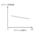
次に、エンジン2に供給される燃料に含まれるアルコール濃度と、ピストン8の頂面温度との関係について説明する。図2は、燃料中のアルコール濃度と、ピストン8の頂面温度との関係を示したグラフである。図2は、横軸が燃料中のアルコール濃度を示しており、縦軸がピストン8の頂面温度を示している。図2に示すように、アルコール濃度が高いほど、ピストン8の頂面温度が低くなることを示している。この理由は、アルコールはガソリンよりも気化潜熱が大きいため、その分だけ筒内温度も低くなり、ピストン8の頂面温度も低くなる傾向があるからである。
Next, the relationship between the alcohol concentration contained in the fuel supplied to the engine 2 and the top surface temperature of the
ECU100は、アルコールセンサ61からの出力に基づいてエンジン2に供給される燃料のアルコール濃度を検出し、この検出結果に基づいてピストン8の頂面の温度を推定し、次に、この推定結果に基づいてオイルジェット70からのオイルの噴射量を制御するオイル噴射量制御処理を実行する。
The
次に、ECU100が実行するオイル噴射量制御処理の一例を説明する。図3は、ECU100が実行するオイル噴射量制御処理の一例を示すフローチャートである。まず、ECU100は、ピストン8の頂面温度Tを推定する推定処理を実行する(ステップS1)。この推定処理については、詳しくは後述する。
次に、ECU100は、推定された頂面温度Tが、限界値Tmaxを超えているか否か、又は、ノックセンサ90cからの出力により、ノッキングが発生しているか否かを判定する(ステップS2)。頂面温度Tが限界値Tmax以下であり、ノッキングも発生していない場合には、本処理を終了する。尚、Tmaxは、ピストン8の頂面温度の影響を受ける各部品の強度や耐久性を考慮して設定された上限値である。
Next, an example of the oil injection amount control process executed by the
Next, the
頂面温度Tが、限界値Tmaxを超えている場合、又はノッキングが発生している場合には、ECU100は、オイルジェット70からピストン8に向けて噴射されるオイルの噴射量が、毎分0.5リットルになるように、制御弁78の作動を制御する(ステップS3)。これにより、ピストン8の頂面温度が低下して、また、ノッキングを抑制しうる。
When the top surface temperature T exceeds the limit value Tmax or when knocking occurs, the
次に、ECU100は、再びピストン8の頂面温度を推定する(ステップS4)。尚、本ステップS4での処理の具体的な方法は、ステップS1での処理を同じである。
Next, the
次に、ECU100は、再度、頂面温度Tが限界値Tmaxを超えているか、又は、ノッキングが発生しているか否かを判定する(ステップS5)。頂面温度Tが所定値Tmax以下であり、ノッキングも発生していない場合には、本処理を終了する。
Next, the
頂面温度Tが、限界値Tmaxを超えている場合、又はノッキングが発生している場合には、オイルジェット70からのオイル噴射量が、許容最大噴射量Qmax未満であるか否かを判定する(ステップS6)。オイルジェット70からのオイル噴射量が、許容最大噴射量Qmax未満の場合には、ECU100は、現在のオイル噴射量に、毎分0.5リットルの噴射量を加算する(ステップS7)。即ち、現在のオイル噴射量が、毎分0.5リットルの場合には、毎分0.5リットルを更に加算することによって、オイル噴射量を毎分1リットルとなるように、ECU100は、制御弁78を制御する。次に、ECU100は、再度ステップS5以降の処理を実行する。このように、オイル噴射量が、許容最大噴射量Qmax未満の場合であって、頂面温度Tが限界値Tmaxを超えており又はノッキングが発生している場合には、オイル噴射量が毎分0.5リットルづつ増量される。このようにオイル噴射量が増量されることにより、ピストン8を冷却し、ノッキングの発生も抑制される。尚、オイル噴射量は、オイルジェット70やオイルポンプ76の性能を考慮して適宜変更してもよい。
When the top surface temperature T exceeds the limit value Tmax, or when knocking occurs, it is determined whether or not the oil injection amount from the
ステップS6において、オイル噴射量が、許容最大量Qmaxであった場合には、ECU100は、頂面温度Tが限界値Tmaxを超えている場合には、スロットル弁の」開度を下げ、ノッキングが発生している場合には、点火プラグ13による点火タイミングを現在よりも遅角側に制御する(ステップS8)。スロットル弁の開度を下げることにより、燃焼室10内に導入される吸気量が減少する。これに伴って、党内温度及びピストン8の頂面温度が低下する。また、点火タイミングを遅角側に制御することにより、ノッキングの発生を防止できる。
In step S6, when the oil injection amount is the allowable maximum amount Qmax, the
次に、ステップS1でECU100が実行した、ピストン8の頂面温度Tの推定処理について説明する。図4は、頂面温度Tの推定処理の一例を示したフローチャートである。
Next, the estimation process of the top surface temperature T of the
図4に示すように、ECU100は、クランク角センサ90a、スロットル開度センサ90bからの出力により、機関回転数Ne、スロットル開度に関する情報を取得する(ステップS11)。次に、ECU100は、これらの情報に基づいて、エンジン2に供給される燃料がガソリン100パーセント時での、ピストン8の頂面温度T0を推定する(ステップS12)。次に、ECU100は、アルコールセンサ61の出力から、インジェクタ60に貯留されている燃料中のアルコール濃度Xを算出する(ステップS13)。
As shown in FIG. 4, the
次に、ECU100は、ピストン8の頂面温度Tを推定する(ステップS14)。具体的には、ステップS13において算出したアルコール濃度Xに基づいて、エンジン2に供給される燃料に含まれるアルコールに起因する、ピストン8の頂面温度の変化量ΔTを算出する。アルコール濃度が多いほど、ピストン8の頂面温度は低下することになる。変化量ΔTは、以下の式により算出できる。
Next, the
(数1)
ΔT=αX・・・・・・(1)
αは補正係数を示し、図2に示したグラフの傾きに相当する。
次に、以下の式により、ピストン8の頂面温度Tを推定する。
(Equation 1)
ΔT = αX (1)
α represents a correction coefficient, which corresponds to the slope of the graph shown in FIG.
Next, the top surface temperature T of the
(数2)
T=T0+ΔT・・・・・・(2)
即ち、エンジン2に供給される燃料がガソリン100パーセント時での、ピストン8の頂面温度T0に、アルコールに基づくピストン8の頂面温度の変化量Δを加算することにより、実際のピストン8の頂面温度を推定する。
(Equation 2)
T = T0 + ΔT (2)
That is, when the amount of fuel supplied to the engine 2 is 100% of gasoline, the change amount Δ of the top surface temperature of the
以上のように、ECU100は、燃料の性状に基づいてピストン8の温度を推定することにより、ピストン8の温度を正確に推定でき、この推定結果に基づいてオイルの噴射量を制御することにより、オイルの噴射量をピストン8の温度に適したものとすることができる。従って、オイルの噴射量が多すぎることによるピストン8の過冷却を防止でき、また、オイルの噴射量が少なすぎることによるピストン8の過度な温度上昇を防止できる。また、無駄なオイルの噴射を防止できる。
As described above, the
図5は、実施例2に係る内燃機関の制御装置が適用されたエンジンシステムの概略構成を示す図である。尚、実施例1に係る内燃機関の制御装置が適用されたエンジンシステムと同様の構成部分については、同様の符号を付することによって、説明を省略する。 FIG. 5 is a diagram illustrating a schematic configuration of an engine system to which the control device for an internal combustion engine according to the second embodiment is applied. In addition, about the component similar to the engine system to which the control apparatus of the internal combustion engine which concerns on Example 1 is applied, description is abbreviate | omitted by attaching | subjecting the same code | symbol.
オイル通路74には、オイルクーラ80が配置されている。オイルクーラ80は、オイルジェット70から噴射されるオイルを冷却するためのものである。オイルクーラ80は、ECU100aからの指令に応じてその冷却温度が制御される。オイルクーラ80とオイルポンプ76との間には、制御弁78aが配置されている。制御弁78aは、ECU100aからの指令に応じて開閉する。
An
また、オイルパン72には、オイルパン72に貯留されているオイルの温度を検出する温度センサ71が設けられている。温度センサ71は、検出信号をECU100aに出力する。
The
ECU100a及びオイルクーラ80は、燃料性状検出手段の検出結果に基づいてピストン8の温度の推定結果に基づいてオイルジェット70によって噴射されるオイルの温度を制御する温度制御手段に相当する。また、ECU100aのROMには、オイル温度制御処理を実行するためのプログラムが格納されており、これら処理の実行過程で取得したデータは、RAMに格納される。
The
次に、ECU100aが実行するオイル温度制御処理の一例を説明する。図6は、ECU100aが実行するオイル温度制御処置の一例を示したフローチャートである。ECU100aは、ステップS1、S2の処理を実行する。尚、この処理は、図3において示したステップS1、S2の処理と同様である。
Next, an example of the oil temperature control process executed by the
次に、ECU100は、温度センサ71からの出力に基づいて、オイルの温度Trを取得する(ステップS2a)。次に、ECU100aは、ステップS1において推定したピストン8の頂面温度に基づいて、オイルクーラ80の設定温度を制御する(ステップS2b)。具体的には、制御弁78aが開弁し、制御弁78が閉弁し、オイルポンプ76によってオイルクーラ80にオイルが圧送された状態でオイルクーラ80の温度を制御する。これにより、オイルクーラ80内に圧送されたオイルは、所定の温度まで冷却される。
Next, the
次に、ECU100aは、制御弁78を開弁させてオイルジェット70からオイルを予め設定された一定量噴射させる(ステップS3a)。次に、ECU100aは、再びピストン8の頂面温度Tを推定する(ステップS4)。
Next, the
次に、ECU100aは、ステップS5の処理を実行する。頂面温度Tが、限界値Tmaxを超えている場合、又はノッキングが発生している場合には、ECU100aは、オイルクーラ80の設定温度が最低値より大きいか否かを判定する(ステップS6a)。最低値とは、オイルクーラ80によって設定可能な温度のうち、最も低温な値をいう。オイルクーラ80の設定温度が最低値よりも大きい場合には、ECU100aは、オイルクーラ80の設定温度を2℃下げる(ステップS7a)。次にECU100aは、オイルジェット70から再び一定量のオイルを噴射させる(ステップS3a)。このように、オイルクーラ80の設定温度が最低値よりも大きい場合であって、頂面温度Tが限界値Tmaxを超えており又はノッキングが発生している場合には、オイルクーラ80の設定温度が下げられることになる。このように、オイルが冷却されることにより、ピストン8を冷却し、ノッキングの発生も抑制される。尚、オイルクーラ80の設定温度は、適宜変更してもよい。
Next, the
尚、ステップS6aにおいて、オイルクーラ80の設定温度が最低値であった場合には、ECU100aは、ステップS8の処理を実行する。
In step S6a, if the set temperature of the
以上のように、ECU100aは、ピストン8の温度の推定結果に基づいてオイルの温度を制御することにより、オイルの温度をピストン8の温度に適したものとすることができる。これにより、ピストン8を早期に冷却することができる。
As described above, the
図7は、実施例3に係る内燃機関の制御装置が適用されたエンジンシステムの概略構成を示す図である。尚、実施例1に係る内燃機関の制御装置が適用されたエンジンシステムと同様の構成部分については、同様の符号を付することによって、説明を省略する。 FIG. 7 is a diagram illustrating a schematic configuration of an engine system to which the control device for an internal combustion engine according to the third embodiment is applied. In addition, about the component similar to the engine system to which the control apparatus of the internal combustion engine which concerns on Example 1 is applied, description is abbreviate | omitted by attaching | subjecting the same code | symbol.
エンジン2aは、気体燃料である水素と液体燃料であるガソリンとをそれぞれ単独又は混合して使用可能に構成されている。燃料タンク62aには、ガソリンのみが単独で貯留される。
The
吸気通路18には、吸気通路18内に水素を噴射するインジェクタ50が気筒毎に設けられている。インジェクタ50は、通電制御により開閉駆動されて水素を噴射する。インジェクタ50は、水素通路54を介して水素タンク52に接続されている。水素通路54にはポンプ56が配置されている。水素タンク52内の水素は、ポンプ56によって圧縮されてインジェクタ50に供給される。
In the
ECU100bは、運転状態に応じてインジェクタ50、60からそれぞれ噴射されるガソリン、水素の総噴射量、ガソリンと水素との噴射割合を制御する。詳細には、ECU100bは、アクセルポジションセンサ(不図示)とクランク角センサ90aからの出力に応じたマップから、目標負荷率を算出する。このマップは、ECU100bのROMに予め記憶されている。従って、ECU100bは、エンジン2aに供給されるガソリンに対する水素の割合を検出する燃料性状検出手段に相当する。
The
次に、ECU100bが実行するオイル噴射量制御処理について説明する。ECU100bは、前述した実施例1に係るECU100と同様に、ピストン8の頂面温度Tを推定し、その推定結果に基づいてオイルジェット70からのオイルの噴射量が制御する。しかしながら、ECU100bは、インジェクタ50から噴射される水素量と、インジェクタ60から噴射されるガソリンの量とに基づいて、ピストン8の頂面温度を推定する。具体的には、エンジン2aに供給される燃料がガソリン100パーセント時での、ピストン8の頂面温度T0に、水素が供給されることに基づくピストン8の頂面温度の変化量を加算することにより、実際のピストン8の頂面温度を推定する。これにより、より詳細にピストン8の頂面温度を推定することができる。
Next, an oil injection amount control process executed by the
以上本発明の好ましい実施形態について詳述したが、本発明は係る特定の実施形態に限定されるものではなく、特許請求の範囲に記載された本発明の要旨の範囲内において、種々の変形・変更が可能である。 Although the preferred embodiments of the present invention have been described in detail above, the present invention is not limited to the specific embodiments, and various modifications and changes can be made within the scope of the gist of the present invention described in the claims. It can be changed.
実施例2において、オイルの温度を制御する温度制御手段として、オイルクーラ80を採用したが、オイルへの加熱温度を設定可能なオイルヒータであってもよい。
In the second embodiment, the
実施例3において、オイルの噴射量を制御するように構成したが、このような構成に限定されず、オイルの温度を制御するオイルクーラ又はオイルヒータを採用して、オイルの温度を制御するようにしてもよい。 In the third embodiment, the oil injection amount is controlled. However, the present invention is not limited to such a configuration, and an oil cooler or an oil heater that controls the oil temperature is employed to control the oil temperature. It may be.
2、2a エンジン
8 ピストン
8a オイル循環路
50、60 インジェクタ
61 アルコールセンサ(燃料性状検出手段)
70 オイルジェット
71 温度センサ
78 制御弁(噴射量制御手段)
80 オイルクーラ(温度制御手段)
100、100a、100c ECU(推定手段、噴射量制御手段、温度制御手段)
2,
70
80 Oil cooler (temperature control means)
100, 100a, 100c ECU (estimating means, injection amount control means, temperature control means)
Claims (4)
前記内燃機関に供給される燃料の性状を検出する燃料性状検出手段と、
前記燃料性状検出手段の検出結果に基づいて前記ピストンの温度を推定する推定手段と、
前記推定手段の推定結果に基づいて前記オイルジェットによって噴射されるオイルの噴射量を制御する噴射量制御手段とを備え、
前記内燃機関は、アルコールとガソリンとをそれぞれ単独又は混合して使用可能であり、
前記燃料性状検出手段は、前記内燃機関に供給される前記燃料中のアルコールの濃度Xを検出し、
前記推定手段は、前記アルコール濃度Xに補正係数αをかけた値を、前記内燃機関に供給される燃料に含まれるアルコールに起因する前記ピストンの温度の変化量ΔTとして算出し、前記内燃機関に供給される燃料中のガソリンの濃度が100パーセントの時の前記ピストンの温度T0に前記変化量ΔTを加算した値を前記ピストンの温度として推定する、ことを特徴とする内燃機関の制御装置。 An oil jet that injects oil toward the piston of the internal combustion engine;
Fuel property detecting means for detecting the property of the fuel supplied to the internal combustion engine;
Estimating means for estimating the temperature of the piston based on the detection result of the fuel property detecting means;
Injection amount control means for controlling the amount of oil injected by the oil jet based on the estimation result of the estimation means ,
The internal combustion engine can be used alone or in combination with alcohol and gasoline,
The fuel property detection means detects the concentration X of alcohol in the fuel supplied to the internal combustion engine,
The estimation means calculates a value obtained by multiplying the alcohol concentration X by a correction coefficient α as a change in temperature ΔT of the piston caused by the alcohol contained in the fuel supplied to the internal combustion engine. A control apparatus for an internal combustion engine, wherein a value obtained by adding the change amount ΔT to the piston temperature T0 when the concentration of gasoline in the supplied fuel is 100% is estimated as the piston temperature .
前記内燃機関に供給される燃料の性状を検出する燃料性状検出手段と、
前記燃料性状検出手段の検出結果に基づいて前記ピストンの温度を推定する推定手段と、
前記推定手段の推定結果に基づいて前記オイルジェットによって噴射されるオイルの温度を制御する温度制御手段を備え、
前記内燃機関は、アルコールとガソリンとをそれぞれ単独又は混合して使用可能であり、
前記燃料性状検出手段は、前記内燃機関に供給される前記燃料中のアルコールの濃度Xを検出し、
前記推定手段は、前記アルコール濃度Xに補正係数αをかけた値を、前記内燃機関に供給される燃料に含まれるアルコールに起因する前記ピストンの温度の変化量ΔTとして算出し、前記内燃機関に供給される燃料中のガソリンの濃度が100パーセントの時の前記ピストンの温度T0に前記変化量ΔTを加算した値を前記ピストンの温度として推定する、ことを特徴とする内燃機関の制御装置。 An oil jet that injects oil toward the piston of the internal combustion engine;
Fuel property detecting means for detecting the property of the fuel supplied to the internal combustion engine;
Estimating means for estimating the temperature of the piston based on the detection result of the fuel property detecting means;
Temperature control means for controlling the temperature of oil injected by the oil jet based on the estimation result of the estimation means ,
The internal combustion engine can be used alone or in combination with alcohol and gasoline,
The fuel property detection means detects the concentration X of alcohol in the fuel supplied to the internal combustion engine,
The estimation means calculates a value obtained by multiplying the alcohol concentration X by a correction coefficient α as a change in temperature ΔT of the piston caused by the alcohol contained in the fuel supplied to the internal combustion engine. A control apparatus for an internal combustion engine, wherein a value obtained by adding the change amount ΔT to the piston temperature T0 when the concentration of gasoline in the supplied fuel is 100% is estimated as the piston temperature .
前記内燃機関に供給される燃料の性状を検出する燃料性状検出手段と、 Fuel property detecting means for detecting the property of the fuel supplied to the internal combustion engine;
前記燃料性状検出手段の検出結果に基づいて前記ピストンの温度を推定する推定手段と、 Estimating means for estimating the temperature of the piston based on the detection result of the fuel property detecting means;
前記推定手段の推定結果に基づいて前記オイルジェットによって噴射されるオイルの噴射量を制御する噴射量制御手段とを備え、 Injection amount control means for controlling the amount of oil injected by the oil jet based on the estimation result of the estimation means,
前記内燃機関は、水素とガソリンとをそれぞれ単独又は混合して使用可能であり、 The internal combustion engine can be used either alone or in combination with hydrogen and gasoline,
前記燃料性状検出手段は、前記内燃機関に供給されるガソリンに対する水素の割合Xを検出し、 The fuel property detecting means detects a ratio X of hydrogen to gasoline supplied to the internal combustion engine,
前記推定手段は、前記割合Xに補正係数αをかけた値を、前記内燃機関に供給される水素に起因する前記ピストンの温度の変化量ΔTとして算出し、前記内燃機関に供給される燃料中のガソリンの濃度が100パーセントの時の前記ピストンの温度T0に前記変化量ΔTを加算した値を前記ピストンの温度として推定する、ことを特徴とする内燃機関の制御装置。 The estimation means calculates a value obtained by multiplying the ratio X by a correction coefficient α as a change amount ΔT of the temperature of the piston caused by hydrogen supplied to the internal combustion engine. A control apparatus for an internal combustion engine, characterized in that a value obtained by adding the change amount ΔT to the piston temperature T0 when the gasoline concentration is 100% is estimated as the piston temperature.
前記内燃機関に供給される燃料の性状を検出する燃料性状検出手段と、 Fuel property detecting means for detecting the property of the fuel supplied to the internal combustion engine;
前記燃料性状検出手段の検出結果に基づいて前記ピストンの温度を推定する推定手段と、 Estimating means for estimating the temperature of the piston based on the detection result of the fuel property detecting means;
前記推定手段の推定結果に基づいて前記オイルジェットによって噴射されるオイルの温度を制御する温度制御手段を備え、 Temperature control means for controlling the temperature of oil injected by the oil jet based on the estimation result of the estimation means,
前記内燃機関は、水素とガソリンとをそれぞれ単独又は混合して使用可能であり、 The internal combustion engine can be used either alone or in combination with hydrogen and gasoline,
前記燃料性状検出手段は、前記内燃機関に供給されるガソリンに対する水素の割合Xを検出し、 The fuel property detecting means detects a ratio X of hydrogen to gasoline supplied to the internal combustion engine,
前記推定手段は、前記割合Xに補正係数αをかけた値を、前記内燃機関に供給される水素に起因する前記ピストンの温度の変化量ΔTとして算出し、前記内燃機関に供給される燃料中のガソリンの濃度が100パーセントの時の前記ピストンの温度T0に前記変化量ΔTを加算した値を前記ピストンの温度として推定する、ことを特徴とする内燃機関の制御装置。 The estimation means calculates a value obtained by multiplying the ratio X by a correction coefficient α as a change amount ΔT of the temperature of the piston caused by hydrogen supplied to the internal combustion engine. A control apparatus for an internal combustion engine, characterized in that a value obtained by adding the change amount ΔT to the piston temperature T0 when the gasoline concentration is 100% is estimated as the piston temperature.
Priority Applications (1)
| Application Number | Priority Date | Filing Date | Title |
|---|---|---|---|
| JP2007320488A JP5109634B2 (en) | 2007-12-12 | 2007-12-12 | Control device for internal combustion engine |
Applications Claiming Priority (1)
| Application Number | Priority Date | Filing Date | Title |
|---|---|---|---|
| JP2007320488A JP5109634B2 (en) | 2007-12-12 | 2007-12-12 | Control device for internal combustion engine |
Publications (2)
| Publication Number | Publication Date |
|---|---|
| JP2009144540A JP2009144540A (en) | 2009-07-02 |
| JP5109634B2 true JP5109634B2 (en) | 2012-12-26 |
Family
ID=40915441
Family Applications (1)
| Application Number | Title | Priority Date | Filing Date |
|---|---|---|---|
| JP2007320488A Expired - Fee Related JP5109634B2 (en) | 2007-12-12 | 2007-12-12 | Control device for internal combustion engine |
Country Status (1)
| Country | Link |
|---|---|
| JP (1) | JP5109634B2 (en) |
Cited By (1)
| Publication number | Priority date | Publication date | Assignee | Title |
|---|---|---|---|---|
| US11939904B2 (en) | 2022-02-18 | 2024-03-26 | Caterpillar Inc. | Optimized piston temperature control in gaseous fuel hydrogen engine system |
Families Citing this family (7)
| Publication number | Priority date | Publication date | Assignee | Title |
|---|---|---|---|---|
| JP5821865B2 (en) * | 2013-02-05 | 2015-11-24 | トヨタ自動車株式会社 | Oil jet abnormality determination device for internal combustion engine and control device for internal combustion engine |
| JP5962534B2 (en) * | 2013-02-15 | 2016-08-03 | トヨタ自動車株式会社 | Intercooler temperature controller |
| JP5854022B2 (en) | 2013-10-04 | 2016-02-09 | トヨタ自動車株式会社 | Oil jet device for internal combustion engine |
| JP6353664B2 (en) * | 2014-02-20 | 2018-07-04 | 日立オートモティブシステムズ株式会社 | Engine control device |
| JP6436122B2 (en) | 2016-03-28 | 2018-12-12 | トヨタ自動車株式会社 | Internal combustion engine |
| JP6919317B2 (en) * | 2017-05-12 | 2021-08-18 | いすゞ自動車株式会社 | Piston temperature estimation device and piston temperature estimation method |
| CN115234356B (en) * | 2022-08-19 | 2024-01-12 | 潍柴动力股份有限公司 | Electric control piston cooling nozzle and control method |
Family Cites Families (7)
| Publication number | Priority date | Publication date | Assignee | Title |
|---|---|---|---|---|
| JP2517988B2 (en) * | 1987-10-26 | 1996-07-24 | 三菱自動車工業株式会社 | Output control device for internal combustion engine |
| JPH0598921A (en) * | 1991-10-11 | 1993-04-20 | Mazda Motor Corp | Lubricating device for alcohol engine |
| JPH05231119A (en) * | 1992-02-25 | 1993-09-07 | Mazda Motor Corp | Lubricating oil feed controller for engine |
| JP3082445B2 (en) * | 1992-07-14 | 2000-08-28 | 日産自動車株式会社 | Multi-fuel engine cooling system |
| JP3332274B2 (en) * | 1993-09-29 | 2002-10-07 | マツダ株式会社 | Control unit for hydrogen engine |
| JP2003148121A (en) * | 2001-11-15 | 2003-05-21 | Aisin Seiki Co Ltd | Lubricating device for internal combustion engine |
| JP4158747B2 (en) * | 2004-06-28 | 2008-10-01 | 日産自動車株式会社 | Ignition timing control device for internal combustion engine |
-
2007
- 2007-12-12 JP JP2007320488A patent/JP5109634B2/en not_active Expired - Fee Related
Cited By (1)
| Publication number | Priority date | Publication date | Assignee | Title |
|---|---|---|---|---|
| US11939904B2 (en) | 2022-02-18 | 2024-03-26 | Caterpillar Inc. | Optimized piston temperature control in gaseous fuel hydrogen engine system |
Also Published As
| Publication number | Publication date |
|---|---|
| JP2009144540A (en) | 2009-07-02 |
Similar Documents
| Publication | Publication Date | Title |
|---|---|---|
| JP5109634B2 (en) | Control device for internal combustion engine | |
| US7258103B2 (en) | Control apparatus for internal combustion engine | |
| US7841316B2 (en) | Controller for direct injection engine | |
| US7747379B2 (en) | Control device of direct injection internal combustion engine | |
| KR100881877B1 (en) | Control apparatus for internal combustion engine | |
| US8150599B2 (en) | Control apparatus and control method for internal combustion engine | |
| JP4103867B2 (en) | Control device for hydrogenated internal combustion engine | |
| US11441509B2 (en) | Fuel injector temperature mitigation | |
| KR100912844B1 (en) | Control apparatus for internal combustion engine | |
| CN104520562B (en) | The control device and control method of internal combustion engine | |
| US9957904B2 (en) | Control apparatus for controlling fuel injection timing and variable valve timing in compression self-ignition internal combustion engine | |
| EP2249015B1 (en) | Engine | |
| JP4387384B2 (en) | Control device for internal combustion engine | |
| JP4296798B2 (en) | Control device for internal combustion engine | |
| JP2000073901A (en) | Fuel supply control device for internal combustion engine | |
| US20130035840A1 (en) | Block heater detection for improved startability | |
| JP4667275B2 (en) | Control device for internal combustion engine | |
| JP2008196311A (en) | Exhaust gas recirculation device for internal combustion engine | |
| JP7622699B2 (en) | Engine Control Unit | |
| JP4576884B2 (en) | Control device and control method for internal combustion engine | |
| JP4618281B2 (en) | Fuel injection control device for internal combustion engine | |
| JP2003083067A (en) | Internal combustion engine piston temperature control device | |
| JP6230337B2 (en) | Control device for internal combustion engine | |
| JP2014206156A (en) | Fuel injection controller of cylinder injection internal combustion engine | |
| JP2008121690A (en) | Control device for hydrogenated internal combustion engine |
Legal Events
| Date | Code | Title | Description |
|---|---|---|---|
| A621 | Written request for application examination |
Free format text: JAPANESE INTERMEDIATE CODE: A621 Effective date: 20101018 |
|
| A131 | Notification of reasons for refusal |
Free format text: JAPANESE INTERMEDIATE CODE: A131 Effective date: 20120131 |
|
| A521 | Written amendment |
Free format text: JAPANESE INTERMEDIATE CODE: A523 Effective date: 20120227 |
|
| TRDD | Decision of grant or rejection written | ||
| A01 | Written decision to grant a patent or to grant a registration (utility model) |
Free format text: JAPANESE INTERMEDIATE CODE: A01 Effective date: 20120911 |
|
| A01 | Written decision to grant a patent or to grant a registration (utility model) |
Free format text: JAPANESE INTERMEDIATE CODE: A01 |
|
| A61 | First payment of annual fees (during grant procedure) |
Free format text: JAPANESE INTERMEDIATE CODE: A61 Effective date: 20120924 |
|
| FPAY | Renewal fee payment (event date is renewal date of database) |
Free format text: PAYMENT UNTIL: 20151019 Year of fee payment: 3 |
|
| FPAY | Renewal fee payment (event date is renewal date of database) |
Free format text: PAYMENT UNTIL: 20151019 Year of fee payment: 3 |
|
| LAPS | Cancellation because of no payment of annual fees |