JP5109320B2 - Sliding member - Google Patents
Sliding member Download PDFInfo
- Publication number
- JP5109320B2 JP5109320B2 JP2006264149A JP2006264149A JP5109320B2 JP 5109320 B2 JP5109320 B2 JP 5109320B2 JP 2006264149 A JP2006264149 A JP 2006264149A JP 2006264149 A JP2006264149 A JP 2006264149A JP 5109320 B2 JP5109320 B2 JP 5109320B2
- Authority
- JP
- Japan
- Prior art keywords
- layer
- dlc film
- hardness
- diamond
- hydrogen content
- Prior art date
- Legal status (The legal status is an assumption and is not a legal conclusion. Google has not performed a legal analysis and makes no representation as to the accuracy of the status listed.)
- Expired - Fee Related
Links
- UFHFLCQGNIYNRP-UHFFFAOYSA-N Hydrogen Chemical compound [H][H] UFHFLCQGNIYNRP-UHFFFAOYSA-N 0.000 claims description 72
- 229910052739 hydrogen Inorganic materials 0.000 claims description 72
- 239000001257 hydrogen Substances 0.000 claims description 72
- 229910052799 carbon Inorganic materials 0.000 claims description 49
- OKTJSMMVPCPJKN-UHFFFAOYSA-N Carbon Chemical compound [C] OKTJSMMVPCPJKN-UHFFFAOYSA-N 0.000 claims description 48
- 239000000314 lubricant Substances 0.000 claims description 19
- 239000005078 molybdenum compound Substances 0.000 claims description 5
- 150000002752 molybdenum compounds Chemical class 0.000 claims description 5
- 239000000758 substrate Substances 0.000 claims description 5
- 150000003752 zinc compounds Chemical class 0.000 claims description 5
- 229910052751 metal Inorganic materials 0.000 claims description 2
- 239000002184 metal Substances 0.000 claims description 2
- 239000010410 layer Substances 0.000 description 153
- 235000019589 hardness Nutrition 0.000 description 123
- 239000000523 sample Substances 0.000 description 39
- 238000004544 sputter deposition Methods 0.000 description 21
- 238000007373 indentation Methods 0.000 description 19
- 239000002344 surface layer Substances 0.000 description 19
- 239000000654 additive Substances 0.000 description 13
- 239000000463 material Substances 0.000 description 12
- 230000000996 additive effect Effects 0.000 description 11
- ZOKXTWBITQBERF-UHFFFAOYSA-N Molybdenum Chemical compound [Mo] ZOKXTWBITQBERF-UHFFFAOYSA-N 0.000 description 10
- 229910052750 molybdenum Inorganic materials 0.000 description 10
- 239000011733 molybdenum Substances 0.000 description 10
- 239000004519 grease Substances 0.000 description 9
- HCHKCACWOHOZIP-UHFFFAOYSA-N Zinc Chemical compound [Zn] HCHKCACWOHOZIP-UHFFFAOYSA-N 0.000 description 8
- 229910052725 zinc Inorganic materials 0.000 description 8
- 239000011701 zinc Substances 0.000 description 8
- NINIDFKCEFEMDL-UHFFFAOYSA-N Sulfur Chemical compound [S] NINIDFKCEFEMDL-UHFFFAOYSA-N 0.000 description 7
- 238000003475 lamination Methods 0.000 description 7
- KHYKFSXXGRUKRE-UHFFFAOYSA-J molybdenum(4+) tetracarbamodithioate Chemical compound C(N)([S-])=S.[Mo+4].C(N)([S-])=S.C(N)([S-])=S.C(N)([S-])=S KHYKFSXXGRUKRE-UHFFFAOYSA-J 0.000 description 7
- 239000011593 sulfur Substances 0.000 description 7
- 229910052717 sulfur Inorganic materials 0.000 description 7
- 239000010687 lubricating oil Substances 0.000 description 6
- 239000007787 solid Substances 0.000 description 6
- 239000011248 coating agent Substances 0.000 description 5
- 238000000576 coating method Methods 0.000 description 5
- 230000000694 effects Effects 0.000 description 5
- 238000000921 elemental analysis Methods 0.000 description 5
- 229910000831 Steel Inorganic materials 0.000 description 4
- 125000004435 hydrogen atom Chemical group [H]* 0.000 description 4
- 239000002356 single layer Substances 0.000 description 4
- 239000010959 steel Substances 0.000 description 4
- VNTLIPZTSJSULJ-UHFFFAOYSA-N chromium molybdenum Chemical compound [Cr].[Mo] VNTLIPZTSJSULJ-UHFFFAOYSA-N 0.000 description 3
- MIMDHDXOBDPUQW-UHFFFAOYSA-N dioctyl decanedioate Chemical group CCCCCCCCOC(=O)CCCCCCCCC(=O)OCCCCCCCC MIMDHDXOBDPUQW-UHFFFAOYSA-N 0.000 description 3
- 238000004453 electron probe microanalysis Methods 0.000 description 3
- 230000001603 reducing effect Effects 0.000 description 3
- 238000009958 sewing Methods 0.000 description 3
- 238000001179 sorption measurement Methods 0.000 description 3
- XLOMVQKBTHCTTD-UHFFFAOYSA-N Zinc monoxide Chemical compound [Zn]=O XLOMVQKBTHCTTD-UHFFFAOYSA-N 0.000 description 2
- 238000005299 abrasion Methods 0.000 description 2
- 239000003575 carbonaceous material Substances 0.000 description 2
- 239000011651 chromium Substances 0.000 description 2
- 238000010586 diagram Methods 0.000 description 2
- 238000002474 experimental method Methods 0.000 description 2
- 238000004519 manufacturing process Methods 0.000 description 2
- 239000012528 membrane Substances 0.000 description 2
- 238000010791 quenching Methods 0.000 description 2
- 230000000171 quenching effect Effects 0.000 description 2
- WMYJOZQKDZZHAC-UHFFFAOYSA-H trizinc;dioxido-sulfanylidene-sulfido-$l^{5}-phosphane Chemical compound [Zn+2].[Zn+2].[Zn+2].[O-]P([O-])([S-])=S.[O-]P([O-])([S-])=S WMYJOZQKDZZHAC-UHFFFAOYSA-H 0.000 description 2
- VYZAMTAEIAYCRO-UHFFFAOYSA-N Chromium Chemical compound [Cr] VYZAMTAEIAYCRO-UHFFFAOYSA-N 0.000 description 1
- 239000005069 Extreme pressure additive Substances 0.000 description 1
- XEEYBQQBJWHFJM-UHFFFAOYSA-N Iron Chemical group [Fe] XEEYBQQBJWHFJM-UHFFFAOYSA-N 0.000 description 1
- 239000000853 adhesive Substances 0.000 description 1
- 230000001070 adhesive effect Effects 0.000 description 1
- 239000012298 atmosphere Substances 0.000 description 1
- 239000002199 base oil Substances 0.000 description 1
- 125000004432 carbon atom Chemical group C* 0.000 description 1
- 238000005255 carburizing Methods 0.000 description 1
- 229910052804 chromium Inorganic materials 0.000 description 1
- 229910003460 diamond Inorganic materials 0.000 description 1
- 239000010432 diamond Substances 0.000 description 1
- 238000010894 electron beam technology Methods 0.000 description 1
- 238000007542 hardness measurement Methods 0.000 description 1
- 239000003879 lubricant additive Substances 0.000 description 1
- 238000001755 magnetron sputter deposition Methods 0.000 description 1
- 238000005259 measurement Methods 0.000 description 1
- 238000000034 method Methods 0.000 description 1
- 239000000203 mixture Substances 0.000 description 1
- 239000003607 modifier Substances 0.000 description 1
- 230000003287 optical effect Effects 0.000 description 1
- 230000000737 periodic effect Effects 0.000 description 1
- 239000011241 protective layer Substances 0.000 description 1
- 238000010008 shearing Methods 0.000 description 1
- 239000000344 soap Substances 0.000 description 1
- 239000000126 substance Substances 0.000 description 1
- JBQYATWDVHIOAR-UHFFFAOYSA-N tellanylidenegermanium Chemical compound [Te]=[Ge] JBQYATWDVHIOAR-UHFFFAOYSA-N 0.000 description 1
- 239000002562 thickening agent Substances 0.000 description 1
- 239000011787 zinc oxide Substances 0.000 description 1
Images


Classifications
-
- F—MECHANICAL ENGINEERING; LIGHTING; HEATING; WEAPONS; BLASTING
- F16—ENGINEERING ELEMENTS AND UNITS; GENERAL MEASURES FOR PRODUCING AND MAINTAINING EFFECTIVE FUNCTIONING OF MACHINES OR INSTALLATIONS; THERMAL INSULATION IN GENERAL
- F16C—SHAFTS; FLEXIBLE SHAFTS; ELEMENTS OR CRANKSHAFT MECHANISMS; ROTARY BODIES OTHER THAN GEARING ELEMENTS; BEARINGS
- F16C33/00—Parts of bearings; Special methods for making bearings or parts thereof
- F16C33/02—Parts of sliding-contact bearings
- F16C33/04—Brasses; Bushes; Linings
- F16C33/043—Sliding surface consisting mainly of ceramics, cermets or hard carbon, e.g. diamond like carbon [DLC]
-
- F—MECHANICAL ENGINEERING; LIGHTING; HEATING; WEAPONS; BLASTING
- F16—ENGINEERING ELEMENTS AND UNITS; GENERAL MEASURES FOR PRODUCING AND MAINTAINING EFFECTIVE FUNCTIONING OF MACHINES OR INSTALLATIONS; THERMAL INSULATION IN GENERAL
- F16C—SHAFTS; FLEXIBLE SHAFTS; ELEMENTS OR CRANKSHAFT MECHANISMS; ROTARY BODIES OTHER THAN GEARING ELEMENTS; BEARINGS
- F16C2206/00—Materials with ceramics, cermets, hard carbon or similar non-metallic hard materials as main constituents
- F16C2206/02—Carbon based material
- F16C2206/04—Diamond like carbon [DLC]
Landscapes
- Engineering & Computer Science (AREA)
- General Engineering & Computer Science (AREA)
- Chemical & Material Sciences (AREA)
- Ceramic Engineering (AREA)
- Mechanical Engineering (AREA)
- Carbon And Carbon Compounds (AREA)
- Lubricants (AREA)
- Physical Vapour Deposition (AREA)
Description
本発明はダイヤモンドライクカーボン層を備えた摺動部材に関し、詳細には、ダイヤモンドライクカーボン層の摺動部材への密着性を高め、且つ、摩擦係数を低くして、優れた摺動性を備えた摺動部材に関する。 The present invention relates to a sliding member provided with a diamond-like carbon layer, and more specifically, the adhesion of the diamond-like carbon layer to the sliding member is increased, and the friction coefficient is lowered to provide excellent sliding properties. The present invention relates to a sliding member.
従来、ダイヤモンドライクカーボン(DLC)は、硬度、耐摩耗性、固体潤滑性、化学的安定性等に優れていることが知られている。そして、このダイヤモンドライクカーボンを表面に設けて、耐摩耗性及び摺動性を高めた摺動部材が提案されている(例えば、特許文献1参照。)。この特許文献1に記載摺動部材では、基材上にCr層、Cr−カーボン層組成傾斜層、ダイヤモンドライクカーボン硬度傾斜層、硬質ダイヤモンドライクカーボンの順に積層した構造の保護層を設けて、保護層の密着性の向上及び摺動性の向上を図っている。
しかしながら、ダイヤモンドライクカーボンは、内部残留応力が高く、高負荷な条件下では、密着性が著しく低くなると言う問題点があり、特許文献1に記載のような構造の摺動部材でも高負荷な条件下では密着性が低下するという問題点があった。また、大気中で優れた低摩耗性、耐摩耗性、耐焼付性及び耐久性を示す水素含有量が少ない硬質ダイヤモンドライクカーボン材料は、潤滑油存在下においては、その摩擦低減効果が必ずしも大きくない。このようなダイヤモンドライクカーボン材料に、ジチオリン酸亜鉛など、極圧添加剤として使用されている有機亜鉛化合物や摩擦調整剤として使用されるジチオカルバミン酸モリブデン(MoDTC)を含有する潤滑油を適用しても、ダイヤモンドライクカーボン表面が極めて安定であり、不活性であるゆえに、これら添加物が表面にて機能せず、摩擦摩耗低減効果は十分に発揮されないという問題点があった。
However, diamond-like carbon has a problem that the internal residual stress is high and the adhesiveness is remarkably lowered under a high load condition. Even a sliding member having a structure as described in
本発明は、上述の課題を解決するためになされたものであり、摺動部材へのダイヤモンドライクカーボンの高い密着性を実現すると共に、低摩擦性を示す摺動部材を提供することを目的とする。 The present invention has been made to solve the above-described problems, and has an object to provide a sliding member that exhibits high adhesion of diamond-like carbon to the sliding member and exhibits low friction. To do.
上記目的を達成するために、請求項1に記載の摺動部材では、基材と、当該基材上に設けられた金属を含む中間層と、当該中間層上に設けられ、当該中間層から離れるに従って、硬度が連続的又は段階的に増加するダイヤモンドライクカーボン層からなる第1ダイヤモンドライクカーボン層と、当該第1ダイヤモンドライクカーボン層上に設けられ、所定硬度のダイヤモンドライクカーボン層からなる低硬度層と当該低硬度層より高い硬度のダイヤモンドライクカーボン層からなる高硬度層とが、前記第1ダイヤモンドライクカーボン層上側から、高硬度層、低硬度層の順に交互に積層された第2ダイヤモンドライクカーボン層とを備え、前記第1ダイヤモンドライクカーボン層及び第2ダイヤモンドライクカーボン層中の水素含有量が20at%〜50at%であり、前記第1ダイヤモンドライクカーボン層の厚みは、50nm〜700nmであり、前記第2ダイヤモンドライクカーボン層の最表面は、前記低硬度層から構成されていることを特徴とする。
In order to achieve the above object, in the sliding member according to
また、請求項2に記載の摺動部材では、請求項1に記載の発明の構成に加え、前記最表面の低硬度層の水素含有量が20at%〜50at%であることを特徴とする。
Further, the sliding member according to
また、請求項3に記載の摺動部材では、請求項1又は2に記載の発明の構成に加え、前記第2ダイヤモンドライクカーボン層の最表面に塗布される潤滑剤には、有機モリブデン化合物及び有機亜鉛化合物を含むことを特徴とする。
In the sliding member according to
請求項1に記載の摺動部材では、前記第1ダイヤモンドライクカーボン層及び第2ダイヤモンドライクカーボン層中の水素含有量が20at%〜50at%であるので、基板あるいは中間下地層との境界において応力の集中が抑制されて、基材と前記第1ダイヤモンドライクカーボン層及び第2ダイヤモンドライクカーボン層との密着性の低下を防止することができる。また、硬度が連続的又は段階的に増加する第1ダイヤモンドライクカーボン層(以下、「傾斜層」とも言う。)の上に、高硬度層、低硬度層の順に交互に積層された積層周期構造を有する第2ダイヤモンドライクカーボン層を設けることにより、表層側の内部応力を抑えて靱性を向上することができる。さらに、摩耗係数が低く摺動性が良好な被膜を得ることが出来る。
In the sliding member according to
また、請求項1に記載の摺動部材では、上記発明の効果に加え、第1ダイヤモンドライクカーボン層の厚みを50nm〜700nmとすることにより、摩耗係数が低く摺動性が良好な被膜を得ることが出来る。
Moreover, in the sliding member according to
また、請求項2に記載の摺動部材では、請求項1に記載の発明の効果に加え、粘着材は、前記第2ダイヤモンドライクカーボン層の最表面の低硬度層の水素含有量が20at%〜50at%であることにより、ダイヤモンドライクカーボン層の表面に、水素基を多く存在させることにより剪断力が低下し、結合力の弱い水素基が摩擦によって脱落することによって、有機亜鉛化合物潤滑剤や有機モリブデン化合物潤滑剤に含まれる成分が吸着しやすい状態とすることによって、トライボケミカル反応被膜が形成され固体潤滑剤としての機能を発揮でき、ダイヤモンドライクカーボンの低摩擦性・低摩耗性をさらに向上できる。
Further, the sliding member according to
また、請求項3に記載の摺動部材では、請求項1又は2に記載の発明の効果に加え、第2ダイヤモンドライクカーボン層の最表面に塗布される潤滑剤には、有機モリブデン化合物及び有機亜鉛化合物を含むので、トライボケミカル反応被膜が形成され固体潤滑剤としての機能を発揮でき、ダイヤモンドライクカーボンの低摩擦性・低摩耗性をさらに向上できる。
In the sliding member according to
以下、本発明の一実施形態である摺動部材について、図面を参照して説明する。図1は、本発明の一実施形態である摺動部材1の断面図の模式図である。本実施の形態の摺動部材1は、鋼材(一例として、クロムモリブデン鋼や超硬合金等)からなる基材5上へ、クロム層からなる中間層6を設け、当該中間層6上へは、ダイヤモンドライクカーボン(以下、「DLC」とも言う。)からなるDLC多層膜10を設けたものである。
Hereinafter, a sliding member according to an embodiment of the present invention will be described with reference to the drawings. FIG. 1 is a schematic diagram of a cross-sectional view of a sliding
そして、このDLC多層膜10は、図1に示すように、中間層6側にDLCの硬度が層内で傾斜した傾斜層12(本発明の第1ダイヤモンドライクカーボン層に相当する)が設けられ、当該傾斜層12上に、DLC膜の積層構造層11(本発明の第2ダイヤモンドライクカーボン層に相当する)が設けられている。尚、DLC多層膜10の生成は、周知のUBMスパッタリング法 (Unbalanced Magnetron sputtering process)を用いて行った。
As shown in FIG. 1, the
次に、傾斜層12について説明する。図1に示すように、摺動部材1では、中間層6側にDLCの硬度が層内で傾斜した傾斜層12が設けられている。この傾斜層12は、1つの層内で、中間層6側は硬度が低く、反対側(積層構造層11側)は硬度が高く形成されているものである。
Next, the
次に、DLC多層膜10を構成する積層構造層11について説明する。図1に示すように、DLC多層膜10を構成する積層構造層11は、硬度の異なるDLC層を交互に積み重ねた複数の層からなるDLCの多層膜である。即ち、本実施の形態の積層構造層11では、傾斜層12側から、高硬度層13、低硬度層14、高硬度層15、低硬度層16、高硬度層17、低硬度層18、高硬度層19、低硬度層20、高硬度層21、低硬度層22と積層している。即ち、この積層構造層11は、DLCの高硬度層と低硬度層のペアを1周期(10nm)として、積層構造層11の膜厚を満たすまで積み重ねて形成している。上記実施の形態では、高硬度層13から低硬度層22までを例示しているが、積層する層数は、これよりも多い場合や、少ない場合でもよく、積層構造層11の必要な膜厚と、高硬度層及び低硬度層の膜厚により積層する層数は決定される。
Next, the laminated structure layer 11 constituting the
次に、図2に示す、試験結果の表を参照して、DLC多層膜10の製造方法とその製造方法により製作されたDLC多層膜10を有する摺動部材1の耐久試験の結果について説明する。図2は、DLC膜を有する試料1〜11のUBMスパッタリング法におけるバイアス電圧、生成されたDLC膜厚比、DLC膜厚、積層周期、耐久試験に於ける耐久性(耐久時間)、内部応力、押込み試験結果、スクラッチ密着試験の於けるスクラッチ密着力を示す一覧表である。
Next, with reference to the test result table shown in FIG. 2, the manufacturing method of the
図2の表に示すように、この試験に用いた摺動部材1については、基材5上に設けられた中間層6上に、DLC膜を単層だけで設けた試料と、積層構造層だけ設けた試料と、傾斜層だけで設けた試料と、傾斜層上に積層構造層を異なる膜厚比で7種類設けた試料の合計11種類を作成して、耐久試験、押込み試験及びスクラッチ密着試験を行った。
As shown in the table of FIG. 2, for the sliding
耐久試験では、天秤軸と天秤軸受とを摺動させて実験を行い、摺動部の寿命を計測した。本実験は、室温40℃の環境で、天秤軸を3300rpmで回転させて、焼き付きが起こるまでの時間(耐久性)を測定した。天秤部分のPV値は、P=1.4MPa、V=6.4m/sである。また、天秤軸に塗布されるグリスは、基油にDOS(セバシン酸ジオクチル)、増ちょう剤にLi石鹸16重量%、添加剤にZnDTp(ジチオリン酸亜鉛)及びMoDTC(ジチオカルバミン酸モリブデン)を5重量%を使用した。尚、DOSの40℃での動粘度は12mm2/sである。 In the durability test, an experiment was performed by sliding the balance shaft and the balance bearing, and the life of the sliding portion was measured. In this experiment, the balance shaft was rotated at 3300 rpm in an environment at a room temperature of 40 ° C., and the time (durability) until seizure occurred was measured. The PV value of the balance part is P = 1.4 MPa and V = 6.4 m / s. The grease applied to the balance shaft is DOS (dioctyl sebacate) as the base oil, 16% by weight of Li soap as the thickener, and 5% of ZnDTp (zinc dithiophosphate) and MoDTC (molybdenum dithiocarbamate) as additives. %It was used. The kinematic viscosity of DOS at 40 ° C. is 12 mm 2 / s.
尚、本耐久試験では、天秤軸と天秤軸受と焼き付きまでの耐久性(耐久時間)を3500時間を合格値とした。この3500時間を合格基準としたのは、一般に工業ミシンでは、1年間に平均700時間程度の実働時間であることが知られている。そうすると、3500時間は5年分の稼働時間となり、3500時間の耐久性を備えたミシンでは、5年に一度潤滑油を給油すれば良いことになる。従来は、1年毎のグリス補給が必要であったが、5年に一度と潤滑油の給油サイクルが非常に長くなり、作業者の潤滑油の供給作業を大幅に削減することができる。また、 焼き付き寿命が3500時間以上になると、約5年のメンテナンスフリーに相当し、工業ミシンの一般的な買い替え寿命が10年といわれているので、製品寿命において、1回の潤滑油の給油(グリスアップ)で済み、作業の軽減効果が大きいからである。 In this endurance test, the balance shaft (balance shaft), balance bearing, and durability until seizure (endurance time) were set to 3500 hours as acceptable values. In general, it is known that an industrial sewing machine has an average working time of about 700 hours per year, with 3500 hours as an acceptance criterion. In that case, 3500 hours become an operation time for 5 years, and in a sewing machine having a durability of 3500 hours, lubricating oil may be supplied once every 5 years. Conventionally, grease replenishment every year has been required, but the lubricating oil supply cycle becomes very long once every five years, and the worker's lubricating oil supply operation can be greatly reduced. In addition, when the seizure life is 3500 hours or more, it corresponds to about 5 years of maintenance-free, and the general replacement life of industrial sewing machines is said to be 10 years. This is because the effect of reducing work is great.
次に、押込み試験について説明する。今回の押込み試験では、ロックウェルCスケール硬度測定用圧子を試料1〜11に押し込み、圧痕周りの剥離の発生の有無を光学顕微鏡にて観察した。圧痕の押し込み荷重としては、150kgfを印加した。
Next, the indentation test will be described. In this indentation test, a Rockwell C scale hardness measurement indenter was pushed into
次に、スクラッチ試験について説明する。スクラッチ試験では、先端半径200μmのロックウェルCスケールのダイヤモンド圧子を試料1〜11に垂直荷重をかけて、一定方向に移動させた。そして、垂直荷重が増加して臨界荷重を越えると圧子進行方向前方の被膜が剥離して接触が圧子と被膜から圧子と基板に変わるため摩擦係数と応力の成分が変化してスクラッチ摩擦力が大きく変化する荷重すなわち摩擦力による臨界荷重が得られる。この臨界荷重を密着力として定量評価した。 Next, the scratch test will be described. In the scratch test, a Rockwell C scale diamond indenter having a tip radius of 200 μm was moved in a certain direction by applying a vertical load to the samples 1-11. When the vertical load increases and exceeds the critical load, the coating in front of the indenter moves away, and the contact changes from the indenter and coating to the indenter and substrate, so the friction coefficient and stress components change and the scratch friction force increases. A critical load due to changing load, ie frictional force, is obtained. This critical load was quantitatively evaluated as the adhesion force.
以下、図2に示す表を参照して、試料1(No:1)〜試料11(No:11)のDLC膜の構造と、試験結果を説明する。まず、試料1(No:1)としては、図2に示すように、UBMスパッタリング法において、バイアス電圧を300Vの一定に維持して、DLC膜を単層の1μmの膜厚のものを作成した。当該DLC膜の水素の含有量は9.7at%である。そして、この試料1では、焼き付きを起こすまでの寿命が900時間の耐久性で、不合格である。そして、試料1のDLC膜の内部応力は、1.3GPaであった。また、押込み試験では、剥離を生じ、スクラッチ密着力は65Nであった。
Hereinafter, with reference to the table shown in FIG. 2, the structure of the DLC film of the sample 1 (No: 1) to the sample 11 (No: 11) and the test result will be described. First, as Sample 1 (No: 1), as shown in FIG. 2, a DLC film having a single layer thickness of 1 μm was prepared by maintaining a bias voltage constant at 300 V in the UBM sputtering method. . The hydrogen content of the DLC film is 9.7 at%. And in this
また、試料2(No:2)としては、図2に示すように、UBMスパッタリング法において、バイアス電圧を300Vの一定に維持して、DLC膜を単層の1μmの膜厚のものを作成した。当該DLC膜の表層100nmまでの平均水素の含有量は33at%である。そして、この試料2では、焼き付きを起こすまでの寿命が1500時間の耐久性で、不合格である。そして、試料2のDLC膜の内部応力は、1.3GPaであった。また、押込み試験では、剥離を生じ、スクラッチ密着力は65Nであった。
As sample 2 (No: 2), as shown in FIG. 2, a DLC film having a single layer thickness of 1 μm was prepared by maintaining the bias voltage constant at 300 V in the UBM sputtering method. . The average hydrogen content up to 100 nm of the surface layer of the DLC film is 33 at%. And in this
また、試料3(No:3)としては、図2に示すように、UBMスパッタリング法において、バイアス電圧を0Vと300Vを交互に印加して、DLC膜を積層構造にして1μmの膜厚のものを作成した。当該DLC膜の表層100nmまでの平均水素の含有量は33at%である。尚、UBMスパッタリング法において、バイアス電圧を0Vとしたときには、硬度の低いDLC膜が形成され、バイアス電圧を300Vとしたときには、硬度の高いDLC膜が形成される。従って、中間層6から硬度の高いDLC膜、硬度の低いDLC膜、硬度の高いDLC膜、硬度の低いDLC膜と交互に積み重ねられ、DLC膜の積層周期は、10nmであり、表層が硬度の低いDLC膜となっている。そして、この試料3では、焼き付きを起こすまでの寿命が2000時間の耐久性で、不合格である。そして、試料3のDLC膜の内部応力は、0.3GPaであった。また、押込み試験では、剥離を生じることが無く、スクラッチ密着力は75Nであった。
Sample 3 (No: 3) has a thickness of 1 μm as shown in FIG. 2 by applying a bias voltage of 0 V and 300 V alternately to form a DLC film in a laminated structure in the UBM sputtering method. It was created. The average hydrogen content up to 100 nm of the surface layer of the DLC film is 33 at%. In the UBM sputtering method, when the bias voltage is set to 0V, a DLC film having a low hardness is formed, and when the bias voltage is set to 300V, a DLC film having a high hardness is formed. Therefore, the
また、試料4(No:4)としては、図2に示すように、UBMスパッタリング法において、バイアス電圧を50V〜300Vに傾斜して昇圧して印加して、1つのDLC膜内にバイアス電圧を50Vで形成した硬度の低い部分からバイアス電圧を300Vで形成した硬度の高い部分まで、DLC膜の硬度を連続的又は段階的に増加する傾斜層とした。この傾斜層は、1μmの膜厚のDLC膜で、当該DLC膜の表層100nmまでの平均水素の含有量は33at%である。この試料4では、焼き付きを起こすまでの寿命が1800時間の耐久性で、不合格である。そして、試料4のDLC膜の内部応力は、1.2GPaであった。また、押込み試験では、亀裂を生じ、スクラッチ密着力は110Nであった。
As shown in FIG. 2, sample 4 (No: 4) is a UBM sputtering method in which a bias voltage is ramped up to 50 V to 300 V and applied, and the bias voltage is applied to one DLC film. The graded layer increases the hardness of the DLC film continuously or stepwise from the low hardness portion formed at 50V to the high hardness portion formed at a bias voltage of 300V. This inclined layer is a DLC film having a thickness of 1 μm, and the average hydrogen content up to 100 nm of the surface layer of the DLC film is 33 at%. In this
また、試料5(No:5)としては、UBMスパッタリング法において、バイアス電圧を50V〜300Vに傾斜して昇圧して印加して、1つのDLC膜内にバイアス電圧を50Vで形成した硬度の低い部分からバイアス電圧を300Vで形成した硬度の高い部分まで、DLC膜の硬度を連続的又は段階的に増加する傾斜層の上に、UBMスパッタリング法において、バイアス電圧を0Vと300Vを交互に印加して、DLC膜を積層構造にして1μmの膜厚のものを作成した。この傾斜層+積層構造のDLC膜の厚みは、1μmであり、当該DLC膜の表層100nmまでの平均水素の含有量は33at%である。従って、中間層6上に傾斜層12が形成され、その上に、硬度の高いDLC膜、硬度の低いDLC膜、硬度の高いDLC膜、硬度の低いDLC膜と交互に積み重ねられ、表層が硬度の低いDLC膜となっている。そして、傾斜層と積層構造との膜厚比は、0.01:0.99であり、全体のDLC膜厚は1μmであり、積層構造のDLC膜の積層周期は、10nmである。そして、この試料5では、焼き付きを起こすまでの寿命が1800時間の耐久性で、不合格である。そして、試料5のDLC膜の内部応力は、0.3GPaであった。また、押込み試験では、剥離を生じることが無く、スクラッチ密着力は75Nであった。
As sample 5 (No: 5), in the UBM sputtering method, the bias voltage is increased to 50 V to 300 V while increasing the voltage, and the bias voltage is formed at 50 V in one DLC film. In the UBM sputtering method, a bias voltage of 0 V and 300 V is applied alternately on a gradient layer that increases the hardness of the DLC film continuously or stepwise from a portion to a high hardness portion formed with a bias voltage of 300 V. Thus, a DLC film having a thickness of 1 μm was formed in a laminated structure. The thickness of the DLC film having the inclined layer + stacked structure is 1 μm, and the average hydrogen content up to 100 nm of the surface layer of the DLC film is 33 at%. Accordingly, the
また、試料6(No:6)としては、UBMスパッタリング法において、バイアス電圧を50V〜300Vに傾斜して昇圧して印加して、1つのDLC膜内にバイアス電圧を50Vで形成した硬度の低い部分からバイアス電圧を300Vで形成した硬度の高い部分まで、DLC膜の硬度を連続的又は段階的に増加する傾斜層の上に、UBMスパッタリング法において、バイアス電圧を0Vと300Vを交互に印加して、DLC膜を積層構造にして1μmの膜厚のものを作成した。この傾斜層+積層構造のDLC膜の厚みは、1μmであり、当該DLC膜の表層100nmまでの平均水素の含有量は33at%である。従って、中間層6上に傾斜層12が形成され、その上に、硬度の高いDLC膜、硬度の低いDLC膜、硬度の高いDLC膜、硬度の低いDLC膜と交互に積み重ねられ、表層が硬度の低いDLC膜となっている。そして、傾斜層と積層構造との膜厚比は、0.05:0.95であり、全体のDLC膜厚は1μmであり、積層構造のDLC膜の積層周期は、10nmである。そして、この試料6では、焼き付きを起こすまでの寿命が3800時間の耐久性で、合格である。そして、試料6のDLC膜の内部応力は、0.3GPaであった。また、押込み試験では、剥離を生じることが無く、スクラッチ密着力は95Nであった。
Further, as sample 6 (No: 6), in the UBM sputtering method, the bias voltage is increased while being inclined from 50 V to 300 V, and the bias voltage is formed at 50 V in one DLC film. In the UBM sputtering method, a bias voltage of 0 V and 300 V is applied alternately on a gradient layer that increases the hardness of the DLC film continuously or stepwise from a portion to a high hardness portion formed with a bias voltage of 300 V. Thus, a DLC film having a thickness of 1 μm was formed in a laminated structure. The thickness of the DLC film having the inclined layer + stacked structure is 1 μm, and the average hydrogen content up to 100 nm of the surface layer of the DLC film is 33 at%. Accordingly, the
また、試料7(No:7)としては、UBMスパッタリング法において、バイアス電圧を50V〜300Vに傾斜して昇圧して印加して、1つのDLC膜内にバイアス電圧を50Vで形成した硬度の低い部分からバイアス電圧を300Vで形成した硬度の高い部分まで、DLC膜の硬度を連続的又は段階的に増加する傾斜層の上に、UBMスパッタリング法において、バイアス電圧を0Vと300Vを交互に印加して、DLC膜を積層構造にして1μmの膜厚のものを作成した。この傾斜層+積層構造のDLC膜の厚みは、1μmであり、当該DLC膜の表層100nmまでの平均水素の含有量は33at%である。従って、中間層6上に傾斜層12が形成され、その上に、硬度の高いDLC膜、硬度の低いDLC膜、硬度の高いDLC膜、硬度の低いDLC膜と交互に積み重ねられ、表層が硬度の低いDLC膜となっている。そして、傾斜層と積層構造との膜厚比は、0.1:0.9であり、全体のDLC膜厚は1μmであり、積層構造のDLC膜の積層周期は、10nmである。そして、この試料7では、焼き付きを起こすまでの寿命が4000時間の耐久性で、合格である。そして、試料7のDLC膜の内部応力は、0.3GPaであった。また、押込み試験では、剥離を生じることが無く、スクラッチ密着力は95Nであった。
As sample 7 (No: 7), in the UBM sputtering method, the bias voltage is inclined and increased to 50 V to 300 V and applied, and the bias voltage is formed at 50 V in one DLC film with low hardness. In the UBM sputtering method, a bias voltage of 0 V and 300 V is applied alternately on a gradient layer that increases the hardness of the DLC film continuously or stepwise from a portion to a high hardness portion formed with a bias voltage of 300 V. Thus, a DLC film having a thickness of 1 μm was formed in a laminated structure. The thickness of the DLC film having the inclined layer + stacked structure is 1 μm, and the average hydrogen content up to 100 nm of the surface layer of the DLC film is 33 at%. Accordingly, the
また、試料8(No:8)としては、UBMスパッタリング法において、バイアス電圧を50V〜300Vに傾斜して昇圧して印加して、1つのDLC膜内にバイアス電圧を50Vで形成した硬度の低い部分からバイアス電圧を300Vで形成した硬度の高い部分まで、DLC膜の硬度を連続的又は段階的に増加する傾斜層の上に、UBMスパッタリング法において、バイアス電圧を0Vと300Vを交互に印加して、DLC膜を積層構造にして1μmの膜厚のものを作成した。この傾斜層+積層構造のDLC膜の厚みは、1μmであり、当該DLC膜の表層100nmまでの平均水素の含有量は33at%である。従って、中間層6上に傾斜層12が形成され、その上に、硬度の高いDLC膜、硬度の低いDLC膜、硬度の高いDLC膜、硬度の低いDLC膜と交互に積み重ねられ、表層が硬度の低いDLC膜となっている。そして、傾斜層と積層構造との膜厚比は、0.3:0.7であり、全体のDLC膜厚は1μmであり、積層構造のDLC膜の積層周期は、10nmである。そして、この試料8では、焼き付きを起こすまでの寿命が4200時間の耐久性で、合格である。そして、試料8のDLC膜の内部応力は、0.3GPaであった。また、押込み試験では、剥離を生じることが無く、スクラッチ密着力は105Nであった。
Further, as sample 8 (No: 8), in the UBM sputtering method, the bias voltage is increased while being inclined from 50 V to 300 V, and the bias voltage is formed in one DLC film at 50 V with low hardness. In the UBM sputtering method, a bias voltage of 0 V and 300 V is applied alternately on a gradient layer that increases the hardness of the DLC film continuously or stepwise from a portion to a high hardness portion formed with a bias voltage of 300 V. Thus, a DLC film having a thickness of 1 μm was formed in a laminated structure. The thickness of the DLC film having the inclined layer + stacked structure is 1 μm, and the average hydrogen content up to 100 nm of the surface layer of the DLC film is 33 at%. Accordingly, the
また、試料9(No:9)としては、UBMスパッタリング法において、バイアス電圧を50V〜300Vに傾斜して昇圧して印加して、1つのDLC膜内にバイアス電圧を50Vで形成した硬度の低い部分からバイアス電圧を300Vで形成した硬度の高い部分まで、DLC膜の硬度を連続的又は段階的に増加する傾斜層の上に、UBMスパッタリング法において、バイアス電圧を0Vと300Vを交互に印加して、DLC膜を積層構造にして1μmの膜厚のものを作成した。この傾斜層+積層構造のDLC膜の厚みは、1μmであり、当該DLC膜の表層100nmまでの平均水素の含有量は33at%である。従って、中間層6上に傾斜層12が形成され、その上に、硬度の高いDLC膜、硬度の低いDLC膜、硬度の高いDLC膜、硬度の低いDLC膜と交互に積み重ねられ、表層が硬度の低いDLC膜となっている。そして、傾斜層と積層構造との膜厚比は、0.5:0.5であり、全体のDLC膜厚は1μmであり、積層構造のDLC膜の積層周期は、10nmである。そして、この試料9では、焼き付きを起こすまでの寿命が4400時間の耐久性で、合格である。そして、試料9のDLC膜の内部応力は、0.3GPaであった。また、押込み試験では、剥離を生じることが無く、スクラッチ密着力は105Nであった。
As sample 9 (No: 9), in UBM sputtering method, the bias voltage was increased to 50 V to 300 V while increasing the bias voltage, and the bias voltage was formed at 50 V in one DLC film with low hardness. In the UBM sputtering method, a bias voltage of 0 V and 300 V is applied alternately on a gradient layer that increases the hardness of the DLC film continuously or stepwise from a portion to a high hardness portion formed with a bias voltage of 300 V. Thus, a DLC film having a thickness of 1 μm was formed in a laminated structure. The thickness of the DLC film having the inclined layer + stacked structure is 1 μm, and the average hydrogen content up to 100 nm of the surface layer of the DLC film is 33 at%. Accordingly, the
また、試料10(No:10)としては、UBMスパッタリング法において、バイアス電圧を50V〜300Vに傾斜して昇圧して印加して、1つのDLC膜内にバイアス電圧を50Vで形成した硬度の低い部分からバイアス電圧を300Vで形成した硬度の高い部分まで、DLC膜の硬度を連続的又は段階的に増加する傾斜層の上に、UBMスパッタリング法において、バイアス電圧を0Vと300Vを交互に印加して、DLC膜を積層構造にして1μmの膜厚のものを作成した。この傾斜層+積層構造のDLC膜の厚みは、1μmであり、当該DLC膜の表層100nmまでの平均水素の含有量は33at%である。従って、中間層6上に傾斜層12が形成され、その上に、硬度の高いDLC膜、硬度の低いDLC膜、硬度の高いDLC膜、硬度の低いDLC膜と交互に積み重ねられ、表層が硬度の低いDLC膜となっている。そして、傾斜層と積層構造との膜厚比は、0.7:0.3であり、全体のDLC膜厚は1μmであり、積層構造のDLC膜の積層周期は、10nmである。そして、この試料10では、焼き付きを起こすまでの寿命が4000時間の耐久性で、合格である。そして、試料10のDLC膜の内部応力は、0.5GPaであった。また、押込み試験では、剥離を生じることが無く、スクラッチ密着力は110Nであった。
Further, as sample 10 (No: 10), in the UBM sputtering method, the bias voltage is increased to 50 V to 300 V while being increased and applied, and the bias voltage is formed at 50 V in one DLC film with low hardness. In the UBM sputtering method, a bias voltage of 0 V and 300 V is applied alternately on a gradient layer that increases the hardness of the DLC film continuously or stepwise from a portion to a high hardness portion formed with a bias voltage of 300 V. Thus, a DLC film having a thickness of 1 μm was formed in a laminated structure. The thickness of the DLC film having the inclined layer + stacked structure is 1 μm, and the average hydrogen content up to 100 nm of the surface layer of the DLC film is 33 at%. Accordingly, the
また、試料11(No:11)としては、UBMスパッタリング法において、バイアス電圧を50V〜300Vに傾斜して昇圧して印加して、1つのDLC膜内にバイアス電圧を50Vで形成した硬度の低い部分からバイアス電圧を300Vで形成した硬度の高い部分まで、DLC膜の硬度を連続的又は段階的に増加する傾斜層の上に、UBMスパッタリング法において、バイアス電圧を0Vと300Vを交互に印加して、DLC膜を積層構造にして1μmの膜厚のものを作成した。この傾斜層+積層構造のDLC膜の厚みは、1μmであり、当該DLC膜の表層100nmまでの平均水素の含有量は33at%である。従って、中間層6上に傾斜層12が形成され、その上に、硬度の高いDLC膜、硬度の低いDLC膜、硬度の高いDLC膜、硬度の低いDLC膜と交互に積み重ねられ、表層が硬度の低いDLC膜となっている。そして、傾斜層と積層構造との膜厚比は、0.9:0.1であり、全体のDLC膜厚は1μmであり、積層構造のDLC膜の積層周期は、10nmである。そして、この試料11では、焼き付きを起こすまでの寿命が1800時間の耐久性で、不合格である。そして、試料11のDLC膜の内部応力は、1.2GPaであった。また、押込み試験では、亀裂を生じ、スクラッチ密着力は110Nであった。
Further, as sample 11 (No: 11), in the UBM sputtering method, the bias voltage is increased to 50 V to 300 V while being increased and applied, and the bias voltage is formed at 50 V in one DLC film with low hardness. In the UBM sputtering method, a bias voltage of 0 V and 300 V is applied alternately on a gradient layer that increases the hardness of the DLC film continuously or stepwise from a portion to a high hardness portion formed with a bias voltage of 300 V. Thus, a DLC film having a thickness of 1 μm was formed in a laminated structure. The thickness of the DLC film having the inclined layer + stacked structure is 1 μm, and the average hydrogen content up to 100 nm of the surface layer of the DLC film is 33 at%. Accordingly, the
以上説明した耐久試験結果により、傾斜層12の厚みが50nm〜700nmである試料6〜試料10が3500時間以上の耐久性を示し合格であったので、DLCの傾斜層12の厚みが50nm〜700nmが好ましいことが判明した。
According to the endurance test results described above, since the
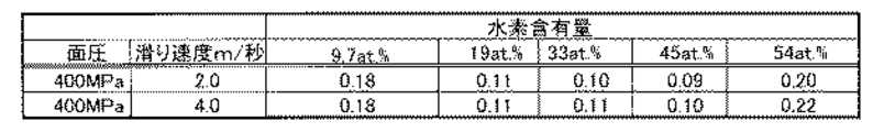
次に、図3及び図4を参照して、DLC膜の水素含有量とピンオンディスク式摩擦摩耗試験機で測定した摩擦係数の関係について説明する。図3は、水素含有量を変えたDLC膜のピンオンディスク式摩擦摩耗試験機で測定した摩擦係数の表であり、図4は、図3に示す表をグラフにしたものである。このピンオンディスク式摩擦摩耗試験では、クロムモリブデン鋼(SCM415浸炭焼き入れ材)のφ55mmからなるディスクにDLC膜の単層コーティングを施して、潤滑剤を塗布して、その上に、先端極率半径8mmの球面ピンを押しつけて、室温30℃、湿度50%で試験距離1000mで、各水素含有量毎に、滑り速度を変えて摩擦摩耗試験を行った。
尚、潤滑剤(グリス)の添加剤としては、ジアルキルジチオリン酸亜鉛(ZnDTP)

In addition, as an additive of lubricant (grease), zinc dialkyldithiophosphate (ZnDTP)
図3及び図4に示すように、球面ピンの面圧が400MPaの時に、球面ピンの滑り速度を2.0m/秒とすると、DLC膜の水素含有量が9.7at%で摩擦係数が0.18、DLC膜の水素含有量が19at%で摩擦係数が0.11、DLC膜の水素含有量が33at%で摩擦係数が0.10、DLC膜の水素含有量が45at%で摩擦係数が0.09、DLC膜の水素含有量が54at%で摩擦係数が0.20である。 As shown in FIGS. 3 and 4, when the spherical pin has a surface pressure of 400 MPa and the sliding speed of the spherical pin is 2.0 m / sec, the hydrogen content of the DLC film is 9.7 at% and the friction coefficient is 0. .18, DLC film hydrogen content 19at% and friction coefficient 0.11, DLC film hydrogen content 33at% and friction coefficient 0.10, DLC film hydrogen content 45at% and friction coefficient The DLC film has a hydrogen content of 54 at% and a friction coefficient of 0.20.
また、図3及び図4に示すように、球面ピンの面圧が400MPaの時に、球面ピンの滑り速度を4.0m/秒とすると、DLC膜の水素含有量が9.7at%で摩擦係数が0.18、DLC膜の水素含有量が19at%で摩擦係数が0.11、DLC膜の水素含有量が33at%で摩擦係数が0.11、DLC膜の水素含有量が45at%で摩擦係数が0.10、DLC膜の水素含有量が54at%で摩擦係数が0.22である。 Further, as shown in FIGS. 3 and 4, when the surface pressure of the spherical pin is 400 MPa and the sliding speed of the spherical pin is 4.0 m / sec, the DLC film has a hydrogen content of 9.7 at% and a friction coefficient. The friction coefficient is 0.18, the hydrogen content of the DLC film is 19 at%, the friction coefficient is 0.11, the hydrogen content of the DLC film is 33 at%, the friction coefficient is 0.11, and the hydrogen content of the DLC film is 45 at%. The coefficient is 0.10, the hydrogen content of the DLC film is 54 at%, and the friction coefficient is 0.22.
従って、上記の実験結果からDLC膜の水素含有量と摩擦係数との関係についてDLC膜の水素含有量が9.7at%の時に摩擦係数が0.18と大きく、また、DLC膜の水素含有量が54at%の時にも摩擦係数が0.20以上と大きい。これは後述のように、水素含有量が9.7at%の時にはDLC表面に潤滑剤(グリス)の添加剤由来の成分の吸着が無いために摩擦係数を上げることになる。また、DLC膜の水素含有量が54at%のときは、DLC膜の硬度が低くなり過ぎて摩耗が進行するために固体接触面積が増大して摩擦係数を上げることになる。これに対して、DLC膜の水素含有量が19at%の時に摩擦係数が0.11、DLC膜の水素含有量が33at%の時に摩擦係数が0.10〜0.11、DLC膜の水素含有量が45at%の時に摩擦係数が0.09〜0.10と小さい。従って、DLC膜の水素含有量が19at%〜45at%であれば、摩擦係数が十分に小さく良好な摺動性を実現することができる。 Therefore, from the above experimental results, the relationship between the hydrogen content of the DLC film and the friction coefficient is as large as 0.18 when the hydrogen content of the DLC film is 9.7 at%, and the hydrogen content of the DLC film. Is 54 at%, the friction coefficient is as large as 0.20 or more. As will be described later, when the hydrogen content is 9.7 at%, the coefficient of friction is increased because there is no adsorption of components derived from the additive of the lubricant (grease) on the DLC surface. Further, when the hydrogen content of the DLC film is 54 at%, the hardness of the DLC film becomes too low and wear progresses, so that the solid contact area increases and the friction coefficient increases. On the other hand, when the hydrogen content of the DLC film is 19 at%, the friction coefficient is 0.11, when the hydrogen content of the DLC film is 33 at%, the friction coefficient is 0.10 to 0.11, and the hydrogen content of the DLC film is When the amount is 45 at%, the friction coefficient is as small as 0.09 to 0.10. Therefore, if the hydrogen content of the DLC film is 19 at% to 45 at%, the friction coefficient is sufficiently small and good slidability can be realized.
次に、図5及び図6を参照して、接触面元素分析結果について説明する。この接触面元素分析は、上記ピンオンディスク式摩擦摩耗試験を行ったクロムモリブデン鋼(SCM415浸炭焼き入れ材)のφ55mmからなるディスクのDLC膜に、潤滑剤(グリス)の添加剤であるジアルキルジチオリン酸亜鉛(ZnDTP)及びジアルキルジチオカルバミン酸モリブデン(MoDTC)由来の亜鉛(Zn)、モリブデン(Mo)、硫黄(S)がどの程度含まれているかを電子線マイクロアナライザ(EPMA: Electron Probe Micro-Analysis)により調べたものである。図5は、DLC膜の水素含有量と、当該DLC膜への潤滑剤(グリス)の添加剤由来の成分の含有量を示す表であり、図6は、図5に示す表をグラフにしたものである。 Next, the contact surface elemental analysis results will be described with reference to FIGS. This contact surface elemental analysis was carried out by using a DLC film of a 55 mm-diameter disk of chromium molybdenum steel (SCM415 carburized quenching material) subjected to the pin-on-disk friction and wear test, and a dialkyldithiophosphorus which is an additive for a lubricant (grease). Electron Probe Micro-Analysis (EPMA) shows how much zinc (Zn), molybdenum (Mo) and sulfur (S) derived from zinc oxide (ZnDTP) and molybdenum dialkyldithiocarbamate (MoDTC) are contained Was investigated. FIG. 5 is a table showing the hydrogen content of the DLC film and the content of the component derived from the additive of the lubricant (grease) to the DLC film, and FIG. 6 is a graph of the table shown in FIG. Is.
図5及び図6に示すように、DLC膜の水素含有量が9.7at%の場合には、亜鉛が0.00at%、モリブデンが0.00at%、硫黄が0.00at%である。また、DLC膜の水素含有量が19at%の場合には、亜鉛が0.45at%、モリブデンが0.09at%、硫黄が0.04at%である。また、DLC膜の水素含有量が33at%の場合には、亜鉛が0.77at%、モリブデンが0.15at%、硫黄が0.12at%である。また、DLC膜の水素含有量が45at%の場合には、亜鉛が0.99at%、モリブデンが0.21at%、硫黄が0.16at%である。また、DLC膜の水素含有量が54at%の場合には、亜鉛が1.03at%、モリブデンが0.24at%、硫黄が0.17at%である。 As shown in FIGS. 5 and 6, when the hydrogen content of the DLC film is 9.7 at%, zinc is 0.00 at%, molybdenum is 0.00 at%, and sulfur is 0.00 at%. Further, when the hydrogen content of the DLC film is 19 at%, zinc is 0.45 at%, molybdenum is 0.09 at%, and sulfur is 0.04 at%. Further, when the hydrogen content of the DLC film is 33 at%, zinc is 0.77 at%, molybdenum is 0.15 at%, and sulfur is 0.12 at%. When the hydrogen content of the DLC film is 45 at%, zinc is 0.99 at%, molybdenum is 0.21 at%, and sulfur is 0.16 at%. When the hydrogen content of the DLC film is 54 at%, zinc is 1.03 at%, molybdenum is 0.24 at%, and sulfur is 0.17 at%.
従って、DLC膜の水素含有量が19at%〜54at%の場合には、DLC膜から潤滑剤(グリス)の添加剤由来の成分を検出することができ、DLC膜表面において添加剤由来の成分が層状構造膜を形成すると考えられ、固体潤滑剤としての機能を発揮すると考えられる。よって、接触面元素分析結果に基づけば、DLC膜の水素含有量が19at%〜54at%が好ましい。これは、従来の鉄部品と同様に、潤滑剤の成分(添加剤)を吸着して、摺動摩擦によりDLC膜にトライボフィルムを形成するからである。それによって潤滑油下での摩擦係数を低減することができるのである。また、上記接触面元素分析結果から潤滑剤には、有機モリブデン化合物及び有機亜鉛化合物を含むことが好ましいことが判明した。これは、DLC膜の水素含有量が19at%以上〜54at%の場合には、潤滑剤の添加剤であるジアルキルジチオリン酸亜鉛(ZnDTP)及びジアルキルジチオカルバミン酸モリブデン(MoDTC)から、亜鉛、モリブデン、硫黄がDLC膜に取り込まれているからである。 Accordingly, when the hydrogen content of the DLC film is 19 at% to 54 at%, the component derived from the additive of the lubricant (grease) can be detected from the DLC film, and the component derived from the additive is present on the DLC film surface. It is considered that a layered structure film is formed, and it is considered that a function as a solid lubricant is exhibited. Therefore, based on the contact surface elemental analysis results, the hydrogen content of the DLC film is preferably 19 at% to 54 at%. This is because, like a conventional iron part, a lubricant component (additive) is adsorbed and a tribo film is formed on the DLC film by sliding friction. As a result, the coefficient of friction under lubricating oil can be reduced. Moreover, it was found from the contact surface elemental analysis results that the lubricant preferably contains an organic molybdenum compound and an organic zinc compound. This is because when the hydrogen content of the DLC film is 19 at% to 54 at%, zinc, molybdenum and sulfur are added from zinc dialkyldithiophosphate (ZnDTP) and molybdenum dialkyldithiocarbamate (MoDTC), which are lubricant additives. This is because is taken into the DLC film.
次に、図7及び図8を参照して、水素含有量とDLC膜硬度の関係について説明する。図7は、水素含有量とDLC膜硬度の関係を示す表であり、図8は、図7の表グラフにしたものである。ここでは、基材を超硬合金とし、その上に各水素含有量のDLC膜を形成したものを、超微小押込み硬さ試験機(ナノインデンテーションテスター)により、DLC膜硬度を調べた。 Next, with reference to FIG.7 and FIG.8, the relationship between hydrogen content and DLC film hardness is demonstrated. FIG. 7 is a table showing the relationship between the hydrogen content and the DLC film hardness, and FIG. 8 is a table graph of FIG. Here, the DLC film hardness was examined using an ultra-fine indentation hardness tester (nanoindentation tester) for a substrate in which a base material was a cemented carbide and a DLC film having each hydrogen content was formed thereon.
図7及び図8に示すように、DLC膜の水素含有量が9.7at%の場合には、硬度が18Gpaであり、DLC膜の水素含有量が19at%の場合には、硬度が16Gpaであり、DLC膜の水素含有量が33at%の場合には、硬度が15Gpaであり、DLC膜の水素含有量が45at%の場合には、硬度が14Gpaであり、DLC膜の水素含有量が54at%の場合には、硬度が6Gpaである。 As shown in FIGS. 7 and 8, when the hydrogen content of the DLC film is 9.7 at%, the hardness is 18 Gpa, and when the hydrogen content of the DLC film is 19 at%, the hardness is 16 Gpa. Yes, when the hydrogen content of the DLC film is 33 at%, the hardness is 15 Gpa, and when the hydrogen content of the DLC film is 45 at%, the hardness is 14 Gpa, and the hydrogen content of the DLC film is 54 at%. In the case of%, the hardness is 6 Gpa.
上記の測定結果からは、DLC膜の水素含有量が9.7at%〜45at%の場合が、DLC膜硬度の低下防止のためには好ましいことが分かる。これは、水素が含有すると、炭素原子間で共有結合する箇所に水素原子が入るため、終端となり、共有結合部分が減少することから過剰な水素の含有は極端な硬度低下を招くからである。従って、水素含有量が50at%を越えると硬度が低くなり過ぎたり、摩耗量が増加し、固体接触面積が増大して摩擦係数を上げることになる。 From the above measurement results, it is understood that the case where the hydrogen content of the DLC film is 9.7 at% to 45 at% is preferable for preventing the decrease in the DLC film hardness. This is because, when hydrogen is contained, hydrogen atoms enter at the sites where covalent bonds are formed between carbon atoms, so that the hydrogen atoms are terminated and the covalent bond portions are reduced. Therefore, excessive hydrogen content causes an extreme decrease in hardness. Accordingly, when the hydrogen content exceeds 50 at%, the hardness becomes too low, the wear amount increases, the solid contact area increases, and the friction coefficient increases.
以上説明したように、本発明の実施形態である摺動部材1によれば、DLC膜の水素含有量とピンオンディスク式摩擦摩耗試験機で測定した摩擦係数の関係では、DLC膜の水素含有量が19at%〜45at%であれば、摩擦係数が十分に小さく良好な摺動性を実現することができることが判明した。また、電子線マイクロアナライザ(EPMA)による接触面元素分析結果によれば、DLC膜が潤滑剤の添加剤成分を吸着するためには、DLC膜の水素含有量が、19at%〜54at%が好ましいことが判明した。また、超微小押込み硬さ試験機によるDLC膜硬度の試験では、DLC膜の水素含有量が9.7at%〜45at%の場合が、硬度10GPa以上を実現できることが判明した。従って、潤滑剤の添加剤成分を吸着させ、且つDLC膜の硬度低下を抑制するためにはDLC膜の水素含有量としては、20at%〜50at%であれば、良いと考えられる。
As described above, according to the sliding
尚、本発明は、上記実施の形態に限られず、各種の軸及び軸受け部材、摺動部材、その他摩擦の生じる部材の摩擦低減に活用することができる。 In addition, this invention is not restricted to the said embodiment, It can utilize for the friction reduction of various shafts, a bearing member, a sliding member, and other members which produce friction.
本発明の摺動部材は、軸及び軸受けに限らず、各種の摩擦面、摺動面を有する機械に適用できる。 The sliding member of the present invention is not limited to a shaft and a bearing, and can be applied to machines having various friction surfaces and sliding surfaces.
1 摺動部材
5 基材
6 中間層
10 DLC多層膜
11 積層構造層
12 傾斜層
13 高硬度層
14 低硬度層
15 高硬度層
16 低硬度層
17 高硬度層
18 低硬度層
19 高硬度層
20 低硬度層
21 高硬度層
22 低硬度層
DESCRIPTION OF
Claims (3)
当該基材上に設けられた金属を含む中間層と、
当該中間層上に設けられ、当該中間層から離れるに従って、硬度が連続的又は段階的に増加するダイヤモンドライクカーボン層からなる第1ダイヤモンドライクカーボン層と、
当該第1ダイヤモンドライクカーボン層上に設けられ、所定硬度のダイヤモンドライクカーボン層からなる低硬度層と当該低硬度層より高い硬度のダイヤモンドライクカーボン層からなる高硬度層とが、前記第1ダイヤモンドライクカーボン層上側から、高硬度層、低硬度層の順に交互に積層された第2ダイヤモンドライクカーボン層とを備え、
前記第1ダイヤモンドライクカーボン層及び第2ダイヤモンドライクカーボン層中の水素含有量が20at%〜50at%であり、
前記第1ダイヤモンドライクカーボン層の厚みは、50nm〜700nmであり、
前記第2ダイヤモンドライクカーボン層の最表面は、前記低硬度層から構成されていることを特徴とする摺動部材。 A substrate;
An intermediate layer comprising a metal provided on the substrate;
A first diamond-like carbon layer comprising a diamond-like carbon layer provided on the intermediate layer and having a hardness that increases continuously or stepwise as the distance from the intermediate layer increases;
The first diamond-like carbon layer includes a low-hardness layer made of a diamond-like carbon layer having a predetermined hardness and a high-hardness layer made of a diamond-like carbon layer having a higher hardness than the low-hardness layer. A second diamond-like carbon layer alternately stacked in the order of a high hardness layer and a low hardness layer from the upper side of the carbon layer;
The hydrogen content of the first diamond-like carbon layer and the second diamond-like carbon layer is Ri 20at% to 50 at% der,
The first diamond-like carbon layer has a thickness of 50 nm to 700 nm,
The uppermost surface of the second diamond-like carbon layer, a sliding member characterized that you have constructed from the low-hardness layer.
Priority Applications (1)
| Application Number | Priority Date | Filing Date | Title |
|---|---|---|---|
| JP2006264149A JP5109320B2 (en) | 2006-09-28 | 2006-09-28 | Sliding member |
Applications Claiming Priority (1)
| Application Number | Priority Date | Filing Date | Title |
|---|---|---|---|
| JP2006264149A JP5109320B2 (en) | 2006-09-28 | 2006-09-28 | Sliding member |
Publications (2)
| Publication Number | Publication Date |
|---|---|
| JP2008081630A JP2008081630A (en) | 2008-04-10 |
| JP5109320B2 true JP5109320B2 (en) | 2012-12-26 |
Family
ID=39352808
Family Applications (1)
| Application Number | Title | Priority Date | Filing Date |
|---|---|---|---|
| JP2006264149A Expired - Fee Related JP5109320B2 (en) | 2006-09-28 | 2006-09-28 | Sliding member |
Country Status (1)
| Country | Link |
|---|---|
| JP (1) | JP5109320B2 (en) |
Families Citing this family (20)
| Publication number | Priority date | Publication date | Assignee | Title |
|---|---|---|---|---|
| JP5352877B2 (en) * | 2008-11-28 | 2013-11-27 | 神奈川県 | DLC coating member and manufacturing method thereof |
| JP5420941B2 (en) * | 2009-03-16 | 2014-02-19 | トヨタ自動車株式会社 | Manufacturing method of sliding member |
| WO2012063735A1 (en) * | 2010-11-09 | 2012-05-18 | 株式会社ニコン | Carbon thin film, mold for molding optical element and method for producing optical element |
| CN103228817A (en) * | 2010-11-30 | 2013-07-31 | 本田技研工业株式会社 | Sliding structural members |
| JP5964943B2 (en) * | 2011-04-07 | 2016-08-03 | シエル・インターナシヨネイル・リサーチ・マーチヤツピイ・ベー・ウイShell Internationale Research Maatschappij Besloten Vennootshap | Lubricant composition and method of using the lubricant composition |
| JP5436486B2 (en) | 2011-04-15 | 2014-03-05 | 株式会社豊田中央研究所 | Sliding member |
| JP6063698B2 (en) | 2011-12-19 | 2017-01-18 | ミネベア株式会社 | Sliding member and fluid dynamic bearing device |
| EP2924142B1 (en) | 2012-05-15 | 2016-11-16 | ZhongAo HuiCheng Technology Co. Ltd. | A nano-multilayer film |
| DE102013200846A1 (en) * | 2013-01-21 | 2014-07-24 | Federal-Mogul Burscheid Gmbh | Sliding element, in particular piston ring, with a coating |
| JP6196170B2 (en) * | 2014-02-10 | 2017-09-13 | 大同メタル工業株式会社 | Sliding member |
| EP3135310B1 (en) * | 2014-04-23 | 2020-08-05 | Zhongao Huicheng Technology Co., Ltd. | Artificial joint cup, magnetic control sputtering coating film preparation method |
| JP5941503B2 (en) | 2014-07-11 | 2016-06-29 | 株式会社豊田中央研究所 | Sliding machine |
| WO2016098217A1 (en) * | 2014-12-17 | 2016-06-23 | オーエスジー株式会社 | Amorphous carbon coating film and amorphous-carbon-coating-film-covered tool |
| CN105734527B (en) * | 2016-03-08 | 2019-01-18 | 仪征亚新科双环活塞环有限公司 | A kind of diamond-like coating, piston ring and preparation process for piston ring surface |
| JP6357607B1 (en) * | 2017-03-31 | 2018-07-11 | 株式会社リケン | Sliding member and piston ring |
| CN110446883B (en) | 2017-03-31 | 2020-10-09 | 株式会社理研 | Sliding member and piston ring |
| EP3604782B1 (en) * | 2017-03-31 | 2024-07-03 | Kabushiki Kaisha Riken | Sliding member, piston ring and method of manufacturing a sliding member |
| JP6357606B1 (en) * | 2017-03-31 | 2018-07-11 | 株式会社リケン | Sliding member and piston ring |
| CN113551034B (en) * | 2021-07-28 | 2024-07-23 | 安庆帝伯格茨活塞环有限公司 | Double transition layer diamond-like coating piston ring |
| CN117987773B (en) * | 2024-02-01 | 2024-08-09 | 仪征亚新科双环活塞环有限公司 | Wear-resistant low-friction coating piston ring and preparation method thereof |
Family Cites Families (10)
| Publication number | Priority date | Publication date | Assignee | Title |
|---|---|---|---|---|
| JP2610469B2 (en) * | 1988-02-26 | 1997-05-14 | 株式会社 半導体エネルギー研究所 | Method for forming carbon or carbon-based coating |
| JPH05202477A (en) * | 1992-01-27 | 1993-08-10 | Sumitomo Electric Ind Ltd | Hard carbon film and its production |
| JP2990220B2 (en) * | 1994-07-30 | 1999-12-13 | 株式会社半導体エネルギー研究所 | Carbon or carbon-based coating |
| JPH0940494A (en) * | 1995-05-19 | 1997-02-10 | Sanyo Electric Co Ltd | Hard carbon film and its formation |
| JP3561611B2 (en) * | 1997-09-25 | 2004-09-02 | 三洋電機株式会社 | Hard carbon coating |
| JP4730753B2 (en) * | 2000-03-23 | 2011-07-20 | 株式会社神戸製鋼所 | Diamond-like carbon hard multilayer film and members with excellent wear resistance and sliding resistance |
| JP3995900B2 (en) * | 2001-04-25 | 2007-10-24 | 株式会社神戸製鋼所 | Diamond-like carbon multilayer film |
| JP4085699B2 (en) * | 2002-06-04 | 2008-05-14 | トヨタ自動車株式会社 | Sliding member and manufacturing method thereof |
| JP2004269991A (en) * | 2003-03-11 | 2004-09-30 | National Institute Of Advanced Industrial & Technology | Diamond-like carbon multilayer film with excellent wear resistance in different environments |
| JP2006161075A (en) * | 2004-12-03 | 2006-06-22 | Shinko Seiki Co Ltd | Hard carbon film, and its depositing method |
-
2006
- 2006-09-28 JP JP2006264149A patent/JP5109320B2/en not_active Expired - Fee Related
Also Published As
| Publication number | Publication date |
|---|---|
| JP2008081630A (en) | 2008-04-10 |
Similar Documents
| Publication | Publication Date | Title |
|---|---|---|
| JP5109320B2 (en) | Sliding member | |
| Watanabe et al. | Tribological characteristics of WS2/MoS2 solid lubricating multilayer films | |
| US9090965B2 (en) | Slide part | |
| Kalin et al. | Differences in the tribological mechanisms when using non-doped, metal-doped (Ti, WC), and non-metal-doped (Si) diamond-like carbon against steel under boundary lubrication, with and without oil additives | |
| Fontaine et al. | Fundamentals of the tribology of DLC coatings | |
| CN102822546B (en) | Rolling bearing | |
| JP5982408B2 (en) | Sliding components coated with a metal-containing carbon layer to improve wear and friction behavior for tribological applications under lubricated conditions | |
| JP4784248B2 (en) | Sliding structure and sliding method | |
| Kharanzhevskiy et al. | Tribological performance of boron-based superhard coatings sliding against different materials | |
| Yamada et al. | Effect of fracture properties and surface morphology on wear of DLC coatings at severe contact condition | |
| Narayana et al. | Enhancing fretting wear behavior of Ti64 alloy: The impact of surface textures and CrN-MoS2-Ag composite coating | |
| Yang | Wear resistance and solid lubricity of molybdenum-containing nitride coatings deposited by cathodic arc evaporation | |
| bin Taib et al. | The effects of oil additives and mating materials to the friction, wear and seizure characteristics of aC: H coating | |
| Zhang et al. | Microstructure and friction behavior of LaF3 doped Ti-MoS2 composite thin films deposited by unbalanced magnetron sputtering | |
| Singh et al. | Effect of lubrication on the wear behaviour of CrN coating deposited by PVD process | |
| Liu et al. | Wear transitions and mechanisms in lubricated sliding of a molybdenum coating | |
| Wang et al. | Fracture toughness and sliding properties of magnetron sputtered CrBC and CrBCN coatings | |
| Gant et al. | The wear and friction behaviour of engineering coatings in ambient air and dry nitrogen | |
| US9790447B2 (en) | Sliding system | |
| Al-Asadi et al. | The effect of diamond like carbon coating on the wear resistance at dry sliding conditions | |
| Vengudusamy et al. | Influence of silicon on the wear properties of amorphous carbon under dry and lubricated conditions | |
| JP2009052081A (en) | Hard carbon coating | |
| Kao et al. | Optimum MoS2–Cr coating for sliding against copper, steel and ceramic balls | |
| Vuchkov et al. | Tribological study of WS-(C) sputtered coatings sliding against aluminium at elevated temperatures | |
| Kuhn et al. | Wear and friction characteristics of PVD-coated roller bearings |
Legal Events
| Date | Code | Title | Description |
|---|---|---|---|
| RD04 | Notification of resignation of power of attorney |
Free format text: JAPANESE INTERMEDIATE CODE: A7424 Effective date: 20080223 |
|
| A621 | Written request for application examination |
Free format text: JAPANESE INTERMEDIATE CODE: A621 Effective date: 20090804 |
|
| A131 | Notification of reasons for refusal |
Free format text: JAPANESE INTERMEDIATE CODE: A131 Effective date: 20120508 |
|
| A521 | Request for written amendment filed |
Free format text: JAPANESE INTERMEDIATE CODE: A523 Effective date: 20120704 |
|
| TRDD | Decision of grant or rejection written | ||
| A01 | Written decision to grant a patent or to grant a registration (utility model) |
Free format text: JAPANESE INTERMEDIATE CODE: A01 Effective date: 20120911 |
|
| A01 | Written decision to grant a patent or to grant a registration (utility model) |
Free format text: JAPANESE INTERMEDIATE CODE: A01 |
|
| A61 | First payment of annual fees (during grant procedure) |
Free format text: JAPANESE INTERMEDIATE CODE: A61 Effective date: 20120924 |
|
| FPAY | Renewal fee payment (event date is renewal date of database) |
Free format text: PAYMENT UNTIL: 20151019 Year of fee payment: 3 |
|
| R150 | Certificate of patent or registration of utility model |
Ref document number: 5109320 Country of ref document: JP Free format text: JAPANESE INTERMEDIATE CODE: R150 Free format text: JAPANESE INTERMEDIATE CODE: R150 |
|
| LAPS | Cancellation because of no payment of annual fees |