JP5105589B2 - X-ray CT system - Google Patents
X-ray CT system Download PDFInfo
- Publication number
- JP5105589B2 JP5105589B2 JP2007181725A JP2007181725A JP5105589B2 JP 5105589 B2 JP5105589 B2 JP 5105589B2 JP 2007181725 A JP2007181725 A JP 2007181725A JP 2007181725 A JP2007181725 A JP 2007181725A JP 5105589 B2 JP5105589 B2 JP 5105589B2
- Authority
- JP
- Japan
- Prior art keywords
- ray
- identification map
- unit
- types
- identification
- Prior art date
- Legal status (The legal status is an assumption and is not a legal conclusion. Google has not performed a legal analysis and makes no representation as to the accuracy of the status listed.)
- Active
Links
- 238000010521 absorption reaction Methods 0.000 claims description 99
- 239000000203 mixture Substances 0.000 claims description 67
- 238000000034 method Methods 0.000 claims description 57
- 238000004364 calculation method Methods 0.000 claims description 36
- 230000008859 change Effects 0.000 claims description 19
- 238000001228 spectrum Methods 0.000 claims description 19
- 238000001514 detection method Methods 0.000 claims description 15
- 230000008569 process Effects 0.000 claims description 11
- 238000013500 data storage Methods 0.000 claims description 7
- 210000001519 tissue Anatomy 0.000 description 101
- 238000003384 imaging method Methods 0.000 description 83
- 230000008520 organization Effects 0.000 description 34
- 238000009826 distribution Methods 0.000 description 32
- 238000012545 processing Methods 0.000 description 23
- 238000003860 storage Methods 0.000 description 19
- 230000006870 function Effects 0.000 description 16
- 238000002474 experimental method Methods 0.000 description 14
- 210000000988 bone and bone Anatomy 0.000 description 12
- 230000009977 dual effect Effects 0.000 description 11
- 210000004204 blood vessel Anatomy 0.000 description 10
- 238000011156 evaluation Methods 0.000 description 8
- JOYRKODLDBILNP-UHFFFAOYSA-N Ethyl urethane Chemical compound CCOC(N)=O JOYRKODLDBILNP-UHFFFAOYSA-N 0.000 description 6
- 238000007689 inspection Methods 0.000 description 5
- 238000012790 confirmation Methods 0.000 description 4
- 239000002872 contrast media Substances 0.000 description 4
- 238000004088 simulation Methods 0.000 description 4
- 230000008901 benefit Effects 0.000 description 3
- 238000010586 diagram Methods 0.000 description 3
- 239000002360 explosive Substances 0.000 description 3
- 210000000056 organ Anatomy 0.000 description 3
- 208000004434 Calcinosis Diseases 0.000 description 2
- 210000001015 abdomen Anatomy 0.000 description 2
- 230000002308 calcification Effects 0.000 description 2
- 238000007796 conventional method Methods 0.000 description 2
- 230000001066 destructive effect Effects 0.000 description 2
- 238000010894 electron beam technology Methods 0.000 description 2
- 239000010410 layer Substances 0.000 description 2
- 230000007246 mechanism Effects 0.000 description 2
- OYPRJOBELJOOCE-UHFFFAOYSA-N Calcium Chemical compound [Ca] OYPRJOBELJOOCE-UHFFFAOYSA-N 0.000 description 1
- 238000000342 Monte Carlo simulation Methods 0.000 description 1
- 206010028980 Neoplasm Diseases 0.000 description 1
- 239000008280 blood Substances 0.000 description 1
- 210000004369 blood Anatomy 0.000 description 1
- 229910052791 calcium Inorganic materials 0.000 description 1
- 239000011575 calcium Substances 0.000 description 1
- 238000004040 coloring Methods 0.000 description 1
- 229940039231 contrast media Drugs 0.000 description 1
- 238000013480 data collection Methods 0.000 description 1
- 230000007423 decrease Effects 0.000 description 1
- 239000002355 dual-layer Substances 0.000 description 1
- 238000005516 engineering process Methods 0.000 description 1
- 210000004394 hip joint Anatomy 0.000 description 1
- 230000001678 irradiating effect Effects 0.000 description 1
- 239000004973 liquid crystal related substance Substances 0.000 description 1
- 238000002360 preparation method Methods 0.000 description 1
- 230000009467 reduction Effects 0.000 description 1
- 230000004044 response Effects 0.000 description 1
- 238000005070 sampling Methods 0.000 description 1
- XLYOFNOQVPJJNP-UHFFFAOYSA-N water Substances O XLYOFNOQVPJJNP-UHFFFAOYSA-N 0.000 description 1
Images


Classifications
-
- A—HUMAN NECESSITIES
- A61—MEDICAL OR VETERINARY SCIENCE; HYGIENE
- A61B—DIAGNOSIS; SURGERY; IDENTIFICATION
- A61B6/00—Apparatus or devices for radiation diagnosis; Apparatus or devices for radiation diagnosis combined with radiation therapy equipment
- A61B6/40—Arrangements for generating radiation specially adapted for radiation diagnosis
- A61B6/405—Source units specially adapted to modify characteristics of the beam during the data acquisition process
-
- A—HUMAN NECESSITIES
- A61—MEDICAL OR VETERINARY SCIENCE; HYGIENE
- A61B—DIAGNOSIS; SURGERY; IDENTIFICATION
- A61B6/00—Apparatus or devices for radiation diagnosis; Apparatus or devices for radiation diagnosis combined with radiation therapy equipment
- A61B6/02—Arrangements for diagnosis sequentially in different planes; Stereoscopic radiation diagnosis
- A61B6/03—Computed tomography [CT]
- A61B6/032—Transmission computed tomography [CT]
-
- A—HUMAN NECESSITIES
- A61—MEDICAL OR VETERINARY SCIENCE; HYGIENE
- A61B—DIAGNOSIS; SURGERY; IDENTIFICATION
- A61B6/00—Apparatus or devices for radiation diagnosis; Apparatus or devices for radiation diagnosis combined with radiation therapy equipment
- A61B6/42—Arrangements for detecting radiation specially adapted for radiation diagnosis
- A61B6/4208—Arrangements for detecting radiation specially adapted for radiation diagnosis characterised by using a particular type of detector
- A61B6/4241—Arrangements for detecting radiation specially adapted for radiation diagnosis characterised by using a particular type of detector using energy resolving detectors, e.g. photon counting
-
- A—HUMAN NECESSITIES
- A61—MEDICAL OR VETERINARY SCIENCE; HYGIENE
- A61B—DIAGNOSIS; SURGERY; IDENTIFICATION
- A61B6/00—Apparatus or devices for radiation diagnosis; Apparatus or devices for radiation diagnosis combined with radiation therapy equipment
- A61B6/48—Diagnostic techniques
- A61B6/482—Diagnostic techniques involving multiple energy imaging
-
- A—HUMAN NECESSITIES
- A61—MEDICAL OR VETERINARY SCIENCE; HYGIENE
- A61B—DIAGNOSIS; SURGERY; IDENTIFICATION
- A61B6/00—Apparatus or devices for radiation diagnosis; Apparatus or devices for radiation diagnosis combined with radiation therapy equipment
- A61B6/58—Testing, adjusting or calibrating thereof
- A61B6/582—Calibration
- A61B6/583—Calibration using calibration phantoms
Landscapes
- Health & Medical Sciences (AREA)
- Life Sciences & Earth Sciences (AREA)
- Engineering & Computer Science (AREA)
- Medical Informatics (AREA)
- Radiology & Medical Imaging (AREA)
- Molecular Biology (AREA)
- Biophysics (AREA)
- Nuclear Medicine, Radiotherapy & Molecular Imaging (AREA)
- Optics & Photonics (AREA)
- Pathology (AREA)
- Physics & Mathematics (AREA)
- Biomedical Technology (AREA)
- Heart & Thoracic Surgery (AREA)
- High Energy & Nuclear Physics (AREA)
- Surgery (AREA)
- Animal Behavior & Ethology (AREA)
- General Health & Medical Sciences (AREA)
- Public Health (AREA)
- Veterinary Medicine (AREA)
- Pulmonology (AREA)
- Theoretical Computer Science (AREA)
- Apparatus For Radiation Diagnosis (AREA)
Description
本発明は、X線CT装置に関し、被写体の組成における識別の高精度化ならびに線量の低減技術に関する。 The present invention relates to an X-ray CT apparatus, and relates to a technique for improving the accuracy of identification in a composition of a subject and reducing a dose.
X線CT装置は、被写体の断層画像(以下,CT画像という)を計測する装置であり、画像上の濃度はX線吸収率(以下,吸収率とする)を表す。近年の技術革新により、大量のCT画像が取得できるようになっている。その結果、大量のCT画像を効率良く利用するため、コンピュータによる被写体組成の自動識別機能の重要性が増している。しかし、例えば生体組織の骨、臓器、血管等のように、X線吸収率が近接している組成(組織)については、自動識別が困難な場合がある。 The X-ray CT apparatus is an apparatus for measuring a tomographic image of a subject (hereinafter referred to as a CT image), and the density on the image represents an X-ray absorption rate (hereinafter referred to as an absorption rate). Due to recent technological innovation, a large amount of CT images can be acquired. As a result, in order to efficiently use a large amount of CT images, the importance of an automatic object composition identification function by a computer is increasing. However, it may be difficult to automatically identify a composition (tissue) having a close X-ray absorption rate, such as a bone, organ, blood vessel or the like of a living tissue.
この問題を解決するための技術として、デュアルエネルギー撮影法(以下、DE法という)が提案されている。DE法で撮像を行うデュアルエネルギーX線CT装置は、異なるエネルギースペクトルを有するX線を2種類以上被写体に照射し、2種類以上のX線ごとにCT画像を取得する。得られた2以上のCT画像は、対応する領域において、X線吸収率が異なる値を示す。これは、各組成のX線吸収率は、照射するX線のエネルギースペクトルに依存するためである。よって、予め求めておいた、2種類以上のX線についての被写体領域のX線吸収率と、組成とを対応づけた識別マップを用いることにより、当該被写体領域の組成(組織)を識別した画像を取得することができる。このように、1種類のエネルギースペクトルを有するX線によるX線吸収率では困難であった組成の識別が、2種類以上のエネルギースペクトルを有するX線を用いることで可能となる。識別マップは、実験またはシミュレーションにより予め作成することができる。 As a technique for solving this problem, a dual energy imaging method (hereinafter referred to as DE method) has been proposed. A dual energy X-ray CT apparatus that performs imaging using the DE method irradiates two or more types of X-rays having different energy spectra to acquire a CT image for each of the two or more types of X-rays. The obtained two or more CT images show different values of X-ray absorption in corresponding regions. This is because the X-ray absorption rate of each composition depends on the energy spectrum of the irradiated X-rays. Therefore, an image in which the composition (tissue) of the subject region is identified by using an identification map that associates the X-ray absorption rate of the subject region with the composition for two or more types of X-rays obtained in advance. Can be obtained. In this way, it is possible to identify a composition that has been difficult with the X-ray absorption rate by X-rays having one type of energy spectrum, by using X-rays having two or more types of energy spectra. The identification map can be created in advance by experiment or simulation.
DE法は、例えば空港や税関等に設置されている爆発物検査用のX線CT装置に搭載され、原子番号や密度情報を用いて組成の特定に使用されている。また、特許文献1や特許文献2には、医療現場で利用される生体用X線CT装置において、2種類のエネルギースペクトルを有するX線の撮影データを用いて、血管内の石灰化と骨、血液と軟質プラーク等の識別を行うことが開示されている。非特許文献1の技術では、実験またはシミュレーションにより識別マップを作成し、カルシウムと造影剤の識別を行っている。
従来のデュアルエネルギーX線CT装置では、識別マップ等の識別基準やX線条件(X線エネルギーの組合せ、およびX線出力量)が、撮影部位(以下、識別対象部位という)に応じて必ずしも最適化されていなかった。このため、識別精度の低下や線量増加が生じるという課題があった。 In a conventional dual energy X-ray CT apparatus, an identification standard such as an identification map and an X-ray condition (a combination of X-ray energy and an X-ray output amount) are not necessarily optimal depending on an imaging part (hereinafter referred to as an identification target part). It was not converted. For this reason, there existed a subject that the identification accuracy fell and the dose increased.
識別マップは、識別対象部位やX線条件等の撮影条件の組み合わせごとに異なる内容になるため、精度良く識別を行うためには、撮像条件の組み合わせに対応した最適な識別マップを用いる必要がある。しかし、識別対象部位やX線条件等の撮像条件は、膨大な数の組み合わせが存在し、従来のように実験や計算に基づき予め作成した識別マップを用いる方法では、膨大な数の識別マップを作成しておく必要があり、実現するのは容易ではない。そのため数種類の代表的な識別マップのみを予め用意し、他の撮像条件の場合も、これで代用しているのが現状である。このため、適切な識別マップを選択できず識別精度が低下する。 Since the identification map has different contents for each combination of imaging conditions such as a region to be identified and an X-ray condition, it is necessary to use an optimal identification map corresponding to the combination of imaging conditions in order to perform accurate identification. . However, there are an enormous number of combinations of imaging conditions such as identification target parts and X-ray conditions, and in the conventional method using an identification map created in advance based on experiments and calculations, an enormous number of identification maps are used. It must be created and is not easy to implement. Therefore, at present, only several types of representative identification maps are prepared in advance, and this is substituted for other imaging conditions. For this reason, an appropriate identification map cannot be selected, and the identification accuracy decreases.
X線条件に関しては、操作者の指定に応じて自動的に最適化できることが望ましいが、実際には操作者が経験に基づいて設定している。そのため最適なX線条件で照射を行えず線量の増加に繋がっている。 It is desirable that the X-ray condition can be automatically optimized according to the operator's designation, but actually, the operator sets it based on experience. Therefore, irradiation cannot be performed under optimal X-ray conditions, leading to an increase in dose.
本発明の目的は、デュアルエネルギーX線CT装置において識別マップを最適化することで識別の高精度化を実現することにある。また、本技術を用いることで、従来と同等の識別精度をより少ない線量で実現できるため、線量の低減が可能になる。 An object of the present invention is to achieve high accuracy of identification by optimizing an identification map in a dual energy X-ray CT apparatus. In addition, by using the present technology, it is possible to realize the same identification accuracy as the conventional one with a smaller dose, and thus the dose can be reduced.
上記目的を達成するために、本発明によれば、以下のようなX線CT装置が提供される。
すなわち、本発明の第1の態様のX線CT装置は、複数種類の異なるエネルギースペクトルを有するX線を発生するX線発生部と、被写体透過後の前記X線を検出するX線検出部と、X線検出部の検出信号に基づき複数種類のX線ごとにX線吸収率画像を計算する画像計算部と、複数種類のX線吸収率画像の対応する領域におけるX線吸収率の値を、各X線吸収率と被写体の組成との関係を示す識別マップにあてはめ、領域の組成を識別する識別計算部と、識別マップを作成する識別マップ作成部と、X線発生部のX線照射条件と識別すべき複数の組成との入力を操作者から受け付ける入力部とを有する。ここで、識別マップ作成部は、入力部に入力されたX線照射条件における複数組成の存在確率を、複数種類のX線吸収率値の組み合わせごとに算出し、存在確率が最も大きい組成を、X線吸収率値の組み合わせに対応する組成と決定することにより、識別マップを作成する。このように、第1の態様のX線CT装置は、入力部に入力されたX線照射条件に応じて、識別マップを作成することができるため、最適な識別マップを用いて高精度に組成の識別を行うことができる。
In order to achieve the above object, according to the present invention, the following X-ray CT apparatus is provided.
That is, the X-ray CT apparatus according to the first aspect of the present invention includes an X-ray generation unit that generates X-rays having a plurality of different energy spectra, and an X-ray detection unit that detects the X-rays after being transmitted through a subject. An image calculation unit that calculates an X-ray absorptance image for each of a plurality of types of X-rays based on a detection signal of the X-ray detection unit, and an X-ray absorption rate value in a corresponding region of the plurality of types of X-ray absorptivity images And an identification map indicating the relationship between each X-ray absorption rate and the composition of the subject, an identification calculation unit for identifying the composition of the region, an identification map creating unit for creating an identification map, and X-ray irradiation of the X-ray generation unit An input unit that receives an input of conditions and a plurality of compositions to be identified from an operator. Here, the identification map creation unit calculates the existence probability of a plurality of compositions in the X-ray irradiation conditions input to the input unit for each combination of a plurality of types of X-ray absorption rate values, and determines the composition having the largest existence probability, An identification map is created by determining the composition corresponding to the combination of X-ray absorption values. Thus, since the X-ray CT apparatus of the first aspect can create an identification map according to the X-ray irradiation conditions input to the input unit, the composition can be made with high accuracy using the optimal identification map. Can be identified.
本発明の第2の態様によるX線CT装置では、識別マップ作成部は、入力部に入力されたX線照射条件における組成の存在確率の変化を示す関数を複数種類のX線吸収率を変数として組成ごとに求め、複数種類のX線吸収率をそれぞれ座標軸とする識別マップ空間に、組成ごとの存在確率の変化を示す関数が交差する位置を境界として描くことにより、境界によって隔てられた複数の領域が複数の組成にそれぞれ対応する識別マップを作成する。このように、第2の態様のX線CT装置は、入力部に入力されたX線照射条件に応じて、識別マップを作成することができるため、最適な識別マップを用いて高精度に組成の識別を行うことができる。 In the X-ray CT apparatus according to the second aspect of the present invention, the identification map creation unit uses a function indicating a change in the existence probability of the composition under the X-ray irradiation conditions input to the input unit as a variable of a plurality of types of X-ray absorption rates. As for each composition, and a plurality of types separated by the boundary by drawing the position where the function indicating the change in the existence probability for each composition intersects in the identification map space having a plurality of types of X-ray absorption rates as coordinate axes. An identification map corresponding to each of a plurality of compositions is created. As described above, since the X-ray CT apparatus of the second aspect can create an identification map according to the X-ray irradiation conditions input to the input unit, the composition can be made with high accuracy using the optimum identification map. Can be identified.
本発明の第3の態様によるX線CT装置では、識別マップ作成部は、入力部に入力されたX線照射条件における組成の存在確率の変化を示す関数を複数種類のX線吸収率を変数として組成ごとに求め、複数種類のX線吸収率をそれぞれ座標軸とする識別マップ空間において、存在確率の変化を示す関数に基づき、所定の位置に境界を描くことにより、境界によって隔てられた複数の領域が複数の組成にそれぞれ対応する識別マップを作成する。このように、第3の態様のX線CT装置は、入力部に入力されたX線照射条件に応じて、識別マップを作成することができるため、最適な識別マップを用いて高精度に組成の識別を行うことができる。 In the X-ray CT apparatus according to the third aspect of the present invention, the identification map creation unit uses a function indicating a change in the existence probability of the composition under the X-ray irradiation conditions input to the input unit as a variable of a plurality of types of X-ray absorption rates. In the identification map space having a plurality of types of X-ray absorption rates as coordinate axes, and by drawing a boundary at a predetermined position based on a function indicating a change in existence probability, a plurality of boundaries separated by the boundary are obtained. An identification map in which each region corresponds to a plurality of compositions is created. Thus, since the X-ray CT apparatus of the third aspect can create an identification map according to the X-ray irradiation conditions input to the input unit, the composition can be made with high accuracy using the optimum identification map. Can be identified.
上記第3の態様において、識別マップ作成部は、例えば、存在確率の変化を示す関数と、境界位置とを用いて、予め定めた数式により、全ての前記組成についての誤答率を求め、誤答率が最小となる位置を境界位置と定める構成とする。 In the third aspect, the identification map creation unit obtains an error rate for all the compositions by a predetermined mathematical formula using, for example, a function indicating a change in existence probability and a boundary position, The position where the response rate is minimized is defined as the boundary position.
上記第1〜第3の態様において、識別マップ作成部は、例えば、入力部が受け付け可能な複数の組成について、平均X線吸収率と、X線吸収率の標準偏差とをX線照射条件ごとに予め格納したデータ格納部を含み、入力部が操作者から受け付けたX線照射条件について対応する平均X線吸収率と、X線吸収率の標準偏差をデータ格納部から読み出し、これらを予め定めた数式に代入することにより存在確率を計算により求める。 In the first to third aspects, the identification map creation unit, for example, calculates an average X-ray absorption rate and a standard deviation of the X-ray absorption rate for each X-ray irradiation condition for a plurality of compositions that can be received by the input unit. The data storage unit stored in advance is read out, the average X-ray absorption rate corresponding to the X-ray irradiation conditions received by the input unit from the operator, and the standard deviation of the X-ray absorption rate are read from the data storage unit, and these are set in advance. The existence probability is calculated by substituting it into the formula.
このとき、入力部は、X線照射条件として、例えば、複数種類のX線ごとに管電圧および管電流量の設定を受け付ける。データ格納部には、入力部が受け付け可能な管電圧ごとの平均X線吸収率と、単位管電流量あたりのX線吸収率の標準偏差とが格納されている。識別マップ作成部は、単位管電流量あたりのX線吸収率の標準偏差と、入力部に設定された管電流量と、予め定めた数式とを用いて、X線吸収率の標準偏差を計算により求める。 At this time, the input unit accepts, for example, the setting of the tube voltage and the tube current amount for a plurality of types of X-rays as the X-ray irradiation conditions. The data storage unit stores an average X-ray absorption rate for each tube voltage that can be received by the input unit, and a standard deviation of the X-ray absorption rate per unit tube current amount. The identification map creation unit calculates the standard deviation of the X-ray absorption rate using the standard deviation of the X-ray absorption rate per unit tube current amount, the tube current amount set in the input unit, and a predetermined mathematical formula. Ask for.
上記第2の態様において、識別マップ作成部は、例えば、境界によって隔てられた二つの領域にそれぞれ対応する組成について誤判別が生じる割合を、二つの組成の前記存在確率の変化を示す関数と、境界位置と、予め定めた数式を用いて計算により求め、誤判別が生じる割合が予め定めた閾値より大きい場合には、二つの組成に対応する領域を識別マップ上で結合させ、一つの組成として識別させてもよい。これにより、識別精度が低い組成同士を同一の組成とみなすことができ、識別精度を向上できる。 In the second aspect, the identification map creation unit, for example, the ratio of the occurrence of misclassification with respect to the composition corresponding to each of the two regions separated by the boundary, a function indicating the change in the existence probability of the two compositions, When the ratio of the boundary position and a predetermined mathematical expression is calculated and the rate of occurrence of misclassification is greater than a predetermined threshold, the regions corresponding to the two compositions are combined on the identification map to obtain one composition. You may identify. Thereby, compositions having low identification accuracy can be regarded as the same composition, and the identification accuracy can be improved.
第1〜第3の態様において、入力部は、例えば、識別マップの作成に必要なX線照射条件の一部のみについて設定を受け付けてもよい。この場合、識別マップ作成部は、他のX線照射条件についての複数の候補値を作成し、複数の候補値ごとに識別マップを作成し、得られた複数種類の識別マップについてそれぞれ、識別マップ全体で組織の誤判別が生じる割合を、存在確率の変化を示す関数と、境界位置と、予め定めた数式を用いて計算により求めることにより、誤判別が生じる割合が最も小さい識別マップを選択することができる。これにより、選択した識別マップについての候補値をX線照射条件の最適値として選択することができ、X線照射条件の最適化を図ることができる。 In the first to third aspects, the input unit may accept settings for only a part of the X-ray irradiation conditions necessary for creating the identification map, for example. In this case, the identification map creating unit creates a plurality of candidate values for other X-ray irradiation conditions, creates an identification map for each of the plurality of candidate values, and each of the obtained plural types of identification maps is an identification map. Select the identification map that has the smallest rate of misclassification by calculating the ratio of occurrence of misclassification of the organization by calculation using a function indicating the change in existence probability, the boundary position, and a predetermined mathematical formula. be able to. Thereby, the candidate value about the selected identification map can be selected as the optimum value of the X-ray irradiation condition, and the X-ray irradiation condition can be optimized.
選択したX線照射条件の最適値は、最適なX線照射条件として操作者に対して表示することを可能である。また、X線発生部が、自動で、最適値のX線条件を用いてX線を照射し、X線吸収画像を取得するようにしてもよい。 The optimum value of the selected X-ray irradiation condition can be displayed to the operator as the optimum X-ray irradiation condition. In addition, the X-ray generation unit may automatically irradiate X-rays using an optimal X-ray condition and acquire an X-ray absorption image.
上述の候補値としては、例えば、X線発生部の管電流量について挙げることができ、これにより管電流量の最適化を図ることができる。 As the above-mentioned candidate value, for example, the tube current amount of the X-ray generation unit can be cited, and thereby the tube current amount can be optimized.
入力部は、例えば、X線照射条件として、複数種類のX線の合計照射線量について設定を受け付けるようにする。この場合、識別マップ作成部は、複数種類のX線の照射線量の合計が、設定された合計照射線量を満たすように、複数種類のX線ごとの照射線量の候補値を作成する。また例えば、入力部は、複数種類のX線による被曝線量について設定を受け付け、識別マップ作成部は、複数種類のX線の照射を受けた被写体の合計被曝量が、被曝線量に対応するように、複数種類のX線ごとに照射線量の候補値を作成してもよい。これらにより、操作者は、合計照射線量や被曝量により、容易にX線条件を設定可能になる。 For example, as the X-ray irradiation condition, the input unit accepts a setting for a total irradiation dose of a plurality of types of X-rays. In this case, the identification map creation unit creates a candidate value for the irradiation dose for each of the plurality of types of X-rays so that the total of the irradiation amounts of the plurality of types of X-rays satisfies the set total irradiation dose. In addition, for example, the input unit accepts settings for exposure doses of a plurality of types of X-rays, and the identification map creation unit is configured so that the total exposure dose of a subject that has been irradiated with a plurality of types of X-rays corresponds to the exposure doses. A candidate value for the irradiation dose may be created for each of a plurality of types of X-rays. Thus, the operator can easily set the X-ray conditions according to the total irradiation dose and the exposure dose.
以下、本発明の一実施の形態を図面を参照にして詳細に説明する。なお、全図において、同一機能を有するものは同一符号を付け、その繰り返しの説明は省略する。 Hereinafter, an embodiment of the present invention will be described in detail with reference to the drawings. In all the drawings, components having the same function are denoted by the same reference numerals, and repeated description thereof is omitted.
(第1の実施の形態)
第1の実施の形態のデュアルエネルギーX線CT装置について説明する。このX線CT装置は、概略構成を図1に示したように、入力手段101と、撮影手段102と、画像生成手段103とを有している。入力手段101は、撮影条件入力部110、識別マップ作成部111および組織パラメータ保存部112を含んでいる。撮影手段102は、撮影制御部113、X線発生部1、X線検出部2、ガントリー5および被写体搭載用テーブル7を含んでいる。画像生成手段103は、信号収集部114、再構成処理部115、識別処理部116および画像表示部117を含んでいる。なお、入力手段101および画像生成手段103は、必ずしもX線CT装置と一体である必要はなく、例えばネットワークを介して接続された別の装置によって、その動作を実現させてもよい。
(First embodiment)
A dual energy X-ray CT apparatus according to the first embodiment will be described. The X-ray CT apparatus includes an
図1のデュアルエネルギーX線CT装置を実現するハードウエア構成の一例を図2を用いて説明する。入力手段101の撮影条件入力部110は、図2のように、キーボード120、マウス121、ペンタブレット、タッチパネル等により構成する。識別マップ作成部111は、中央処理装置122およびメモリ123等により構成する。中央処理装置122は、メモリ123に予め格納しておいた所定のプログラムを展開・起動することで識別マップ作成のための処理を行う。組織パラメータ保存部112は、HDD(Hard Disk Drive)装置124等により構成する。なお前記各構成要素は、データバス1101によって接続されている。
An example of a hardware configuration for realizing the dual energy X-ray CT apparatus of FIG. 1 will be described with reference to FIG. As shown in FIG. 2, the photographing
撮影手段102のX線発生部1は、X線管3を含む。X線検出部2は、X線検出器4を含む。ガントリー5の中央には被写体8およびテーブル7を配置するための円形の開口部9が設けられている。ガントリー5内には、X線管3およびX線検出器4を搭載する回転板6と、回転板6を回転させるための不図示の駆動機構とを備えている。テーブル7には、ガントリー5に対する被写体位置を調整するための不図示の駆動機構が備えられている。撮影制御部113は、X線管3を制御するX線制御器126、ガントリー制御器125およびテーブル制御器127を含んでいる。ガントリー制御器125は、回転板6の回転駆動を制御する。テーブル制御器127は、テーブル7の駆動を制御する。
The
X線管3のX線発生点とX線検出器4のX線入力面との距離は、代表例として1000mmに設定することができる。ガントリー5の開口部9の直径は、代表例として700mmに設定することができる。回転板6の回転の所要時間は、代表例として1.0s/回に設定することができる。X線検出器4は、シンチレータ、およびフォトダイオード等から構成される公知のX線検出器を使用することができる。X線検出器4は、X線管3から等距離に多数の検出素子を円弧状に配列した構成であり、その素子数(チャネル数)は、例えば950個である。各検出素子のチャンネル方向のサイズは、例えば1mmである。撮影手段102の1回転における撮影回数は、900回であり、回転板6が0.4度回転する毎に1回の撮影が行われる。なお前記各仕様はこれらの値に限定されるものはなく、X線CT装置の構成に応じて種々変更可能である。
The distance between the X-ray generation point of the
画像生成手段103の信号収集部114は、データ収集システム(DAS;Data Acquisition System)128を含んでいる。DAS128は、X線検出器4の検出結果をディジタル信号に変換する。再構成処理部115と識別処理部116は、中央処理装置122、メモリ123およびHDD装置124を含む。中央処理装置122およびメモリ123において、所定のプログラムを展開・起動することで画像の再構成処理や識別処理等の各種の処理を行う。HDD装置124等は、データの保存や入出力を行う。画像表示部117は、液晶ディスプレイやCRT等のモニタ129により構成される。なお、各構成要素はデータバス1103によって接続されている。
The
つぎに、第1の実施の形態のX線CT装置の動作を説明する。
このX線CT装置は、DE法による撮影を行う機能と一般的な撮影機能とを有している。DE法による撮影は、入力モードと本撮影モードを順に行う。入力モードは、操作者が識別対象部位や管電圧等の撮影条件を入力し、これに基づき最適な識別マップを計算により求めるモードである。本撮影モードは、入力モードで入力した撮影条件に基づきX線を照射しCT画像を生成した後、入力モードで求めた最適な識別マップを用いて、CT画像の組織(被写体8が生体ではない場合は組成)を識別するモードである。モードの選択は、操作者がマウス121やキーボード120等を通して行う。本実施の形態では、撮影モードで用いる撮影条件について、入力モードで識別マップを作成するため、識別マップの最適化を図ることができ、識別の高精度化および線量の低減を実現できる。以下、両モードにおける動作を説明する。
Next, the operation of the X-ray CT apparatus according to the first embodiment will be described.
This X-ray CT apparatus has a function of performing imaging by the DE method and a general imaging function. In the shooting by the DE method, the input mode and the main shooting mode are sequentially performed. The input mode is a mode in which an operator inputs imaging conditions such as a region to be identified and a tube voltage, and obtains an optimum identification map based on this. In this imaging mode, a CT image is generated by irradiating X-rays based on the imaging conditions input in the input mode, and then the CT image tissue (subject 8 is not a living body) using the optimum identification map obtained in the input mode. This is a mode for identifying the composition. The mode is selected by the operator through the
入力モードは、(1)撮影条件設定、(2)識別マップ作成の順で行う。入力モードは、図1の入力手段101の撮影条件入力部110、識別マップ作成部111および組織パラメータ保存部112により実行される。
The input mode is performed in the order of (1) shooting condition setting and (2) identification map creation. The input mode is executed by the imaging
(1)撮影条件設定
撮影条件入力部110は、図3に示すような入力画面をモニタ129もしくは別のモニタに表示する。操作者が、この画面を見ながら、撮影条件入力部110を構成するマウス121やキーボード120等を操作することにより、識別対象部位、識別対象部位に含まれる識別すべき複数の組織の種類、低エネルギーX線照射時の管電圧ELおよび管電流量IL、高エネルギーX線照射時の管電圧EHおよび管電流量IHを設定する。
(1) Shooting Condition Setting The shooting
図3の入力画面には、識別対象部位を選択するための識別部位選択リスト130と、識別すべき組織を選択するための識別組織選択リスト131と、低エネルギーおよび高エネルギーのX線出力量に対応する管電圧および管電流量を設定するためのX線条件入力領域132が含まれている。操作者は、図3の画面の識別部位選択リスト130において、識別対象部位を選択する。例えば部位は胸部、腹部、頭部、頚部、脊椎、股関節、四股等を選択できる。識別部位選択リスト130は、部位に限らず心臓、脂肪、血管等のように、部位を構成する組織を選択する構成にすることもできる。
The input screen of FIG. 3 includes an identification
また、操作者は、識別組織選択リスト131において、造影剤、プラーク各種、石灰化、腫瘍、穿刺器具、カテーテル等の検査用途に応じた組織や、骨、血管、各種臓器等の組織を選択する。このとき、造影剤濃度等の数値表記の可能な組織は、識別組織選択リスト131の数値入力欄において、数値を入力する。X線条件入力領域132では、高エネルギーX線照射時の管電圧EHおよび管電流量IH、低エネルギーX線照射時の管電圧ELおよび管電流量ILをそれぞれ入力する。
Further, the operator selects, in the identified
なお、撮影条件入力のための画面は、図3の画面構成に限られるものではなく、識別対象部位、組織、管電圧および管電流量が設定できる画面構成であれば制限はない。また、事前に撮影条件を保存した場合、それを読み出して用いることができる。この場合、撮影の都度、操作者が入力しなくてもよい。また、図3の画面例では、高低2種類のエネルギースペクトルを有するX線条件を設定するが、3種類以上のX線を用いてDE法で撮影を行うことも可能であり、この場合の管電圧および管電流量の項目を操作者が追加し、設定する構成にすることができる。 Note that the screen for inputting imaging conditions is not limited to the screen configuration of FIG. 3, and there is no limitation as long as the screen configuration can set the identification target region, tissue, tube voltage, and tube current amount. In addition, when shooting conditions are stored in advance, they can be read and used. In this case, the operator does not have to input each time shooting is performed. In the screen example of FIG. 3, X-ray conditions having two types of high and low energy spectra are set, but it is also possible to perform imaging using the DE method using three or more types of X-rays. An operator can add and set items of voltage and tube current amount.
(2)識別マップ作成
識別マップ作成部111は、図4にその処理手順を示したように、撮影条件入力部110に入力された識別対象部位、管電圧および管電流量等の撮影条件に応じて、各組織におけるX線吸収率の存在確率(以下、X線吸収率分布という)から最適な識別マップを計算により求める(ステップ201〜204)。この計算は、組織パラメータ保存部112に予め格納されている、撮影条件毎の各組織のX線吸収率およびX線吸収率の標準偏差を用いて行う。
(2) Creation of identification map As shown in the processing procedure in FIG. 4, the identification
ここで作成する識別マップとは、図5に示したように、低エネルギーX線吸収率μLの値と高エネルギーX線吸収率μHの値をそれぞれx軸y軸にとった2次元マップであり、境界50によって領域51,52,53に分割されたものである。領域51,52,53は、骨、臓器、造影血管等の異なる組織(組成)に対応している。よって、本撮影モードで撮影した低エネルギーX線吸収率画像および高エネルギーX線吸収率画像の対応する画素について、それぞれ画像の示す低エネルギーX線吸収率μLの値と高エネルギーX線吸収率μHの値とを求め、識別マップ上でこれら値によって特定される点が含まれる領域51、52、53を求めることにより、その領域に対応する組織が、X線吸収率画像の、その画素の組織であると識別することができる。識別マップは、撮影条件(管電圧E、管電流量I)の組み合わせごとに、領域51,52,53の境界が異なる形状を示すため、本実施の形態では、入力された撮影条件について、識別マップを計算により作成する(ステップ201〜204)。
The identification map to be created here, as shown in FIG. 5, two-dimensional map taken in the x-axis y-axis respectively the values of the low-energy X-ray absorption factor mu L value and high-energy X-ray absorption factor mu H And divided into
図4に示したように、識別マップ作成部111は、操作者が入力した識別対象部位、識別すべき組織の種類(N個)、低エネルギーと高エネルギーに対応するX線管3の管電圧EL、EHのデータを撮影条件入力部110から取り込んだ後、組織パラメータ保存部112にアクセスすることにより、識別マップの計算に必要なパラメータ(管電圧EL、EHに対応する平均吸収率μave、単位管電流量あたりのX線吸収率の標準偏差σ0)の値であって、取り込んだ撮影条件に対応する値を読み出す(ステップ201)。これにより、管電圧EL、EHに対応する平均吸収率μaveL、μaveH、および各組織の単位管電流量あたりのノイズの標準偏差σ0L、σ0Hを取得することができる。
As shown in FIG. 4, the identification
なお、組織パラメータ保存部112には、図6に示すように、組織ごとに事前に実験またはシミュレーションより求めた、管電圧に対応する平均吸収率μave、および、管電圧に対応する、単位管電流量あたりのX線吸収率の標準偏差σ0を示す組織テーブル140がデータベースとして予め格納されている。図6では、組織パラメータ保存部112に保存されている組織テーブル140の一例として、骨のテーブル141および造影血管のテーブル142を示している。データベースの構成は、図6の構成に限らず、組織ごとの管電圧、平均吸収率、および、単位管電流量あたりのノイズの標準偏差を保存した構成であればどのような構成でもよい。
As shown in FIG. 6, the tissue
つぎに、撮影条件入力部110から操作者が入力した管電流量IL、IHを取り込み、式σL=σ0L/(√IL)、σH=σ0H/(√IH)によりX線吸収率の標準偏差σL、σHを求める(ステップ202)。ステップ201、202で求めた平均吸収率μaveL、μaveHおよび標準偏差σL、σHから、予め定めておいた演算式を用いて2次元X線吸収率分布μ(x,y)を求める(ステップ203)。ここでは、下記の[数1]に示す2次元ガウス分布から平均吸収率μaveL、μaveHを中心とする2次元X線吸収率分布μ(x,y)を近似的に求める(ステップ203)。2次元X線吸収率分布μ(x,y)は、xy平面における、その組織の存在確率の変化を示す関数である。

ただし、xおよびyは、図5の識別マップの座標軸x、yの値であり、xは低エネルギーX線吸収率μL、yは、高エネルギーX線吸収率μHに対応している。また、[数1]の2次元ガウス分布の演算式に限らず、多項式、指数関数、ローレンツ関数等、種々の関数を用いたX線吸収率分布演算式を用いることが可能である。 However, x and y are coordinate axes x, y values of the identification map in FIG. 5, x is a low-energy X-ray attenuation coefficient mu L, y corresponds to the high-energy X-ray attenuation coefficient mu H. In addition, the X-ray absorptivity distribution calculation formula using various functions such as a polynomial, an exponential function, and a Lorentz function can be used instead of the calculation formula for the two-dimensional Gaussian distribution of [Equation 1].
2次元X線吸収率分布μ(x,y)は、操作者が撮影条件入力部101に入力した組織ごとに求める。組織がN個ある場合、k番目(但し、k=1、2・・・N)の組織のX線吸収率分布を以下μk(x,y)で表す。
The two-dimensional X-ray absorption rate distribution μ (x, y) is obtained for each tissue input by the operator to the imaging
つぎに、識別マップの2次元空間を予め定めた微小サイズの画素に分割し、座標(x,y)の画素において、N個の組織のX線吸収率分布μk(x,y)(但し、k=1、2・・・N)の値(頻度)を比較し、最も大きいX線吸収率分布μk(x,y)の組織を当該画素の組織として決定する。識別マップ内のすべての画素について組織を決定することにより、識別マップを作成することができる(ステップ204)。 Next, the two-dimensional space of the identification map is divided into pixels of a predetermined minute size, and the X-ray absorption rate distribution μ k (x, y) of N tissues at the pixel of the coordinate (x, y) (however, , K = 1, 2... N) are compared, and the tissue of the largest X-ray absorption distribution μ k (x, y) is determined as the tissue of the pixel. An identification map can be created by determining the tissue for all pixels in the identification map (step 204).
作成した識別マップは、識別マップ作成部111から識別処理部116に受け渡され、識別処理部116の構成要素であるHDD装置124等に格納される。
The created identification map is transferred from the identification
つぎに、本撮影モードにおけるX線CT装置の動作について説明する。
本撮影モードでは、操作者が、マウス121やキーボード120等を通して撮影位置を指定した後、撮影開始を指示すると、入力モードで操作者が撮影条件入力部101に設定した識別対象部位、高低2種類の管電圧、管電圧ごとの管電流量の条件で撮影を行う。具体的には、テーブル制御器127の制御により、テーブル7は被写体8を回転板6に対して略垂直な方向に移動させ、回転板6の撮影位置が指定された撮影位置と一致した時点で移動を停止する。これにより、被写体8の配置が完了する。一方、ガントリー制御器125は、撮影開始が指示されると同時に駆動モーターを動作させ、回転板6の回転を開始させる。回転板6の回転が定速状態に入り、かつ被写体8の配置が終了した時点で、ガントリー制御器125は、X線管3のX線照射タイミングおよびX線検出器4の撮影タイミングを指示し、撮影を開始する。
Next, the operation of the X-ray CT apparatus in the main imaging mode will be described.
In this photographing mode, when the operator designates a photographing position after specifying the photographing position through the
撮影は、回転板6が2回転する期間中に行われ、前半の1回転ではX線管3の管電圧が高管電圧EHに、また後半の1回転ではX線管3の管電圧が低管電圧ELに設定される。そのため、X線制御器126は、前半の1回転が終了すると同時にX線管3の管電圧を、高管電圧EHから低管電圧ELに切り替える。代表的な管電圧値としては、140kV(高管電圧EH)および80kV(低管電圧EL)を設定することができる。
Imaging is performed during a period in which the
X線検出器4の出力信号は、信号収集部114のDAS128によってディジタル信号に変換され、その信号に対して公知のエアキャリブレーション処理が施される。求められたX線吸収率の情報はメモリ123に保存される。中央処理装置122は、公知のCT画像再構成プログラムを実行することにより、再構成処理部115として動作し、被写体のX線吸収率を表すCT画像を生成する。
The output signal of the
中央処理装置122は、公知の識別プログラムを実行することにより識別処理部116として動作し、生成したCT画像について、入力モードで求めておいた識別マップを適用して、画像の各部位のX線吸収率に対応する組織を識別し、識別画像を求める。中央処理装置122は、計算した識別画像をモニタ129に表示させるとともに、操作者の指示に応じて、識別画像中の組織に対して着色等の強調表示処理を行い、操作者に組織に関する情報を提供する。また、ネットワークアダプタを用いて、ローカルエリアネットワーク、電話回線、インターネット等のネットワークを介して外部の端末と画像生成手段103を接続し、端末との間でCT画像や識別画像を送受信することも可能である。
The
上述の撮影方法では、1回転毎に管電圧を高速に切り替えて2種類以上のエネルギースペクトルを有するX線の撮影データを取得しているが、上記したものとは異なる装置構成や撮影手順によってDE法を行うことも可能である。例えば、ガントリー5内に2組のX線管3とX線検出器4を有し、それぞれのX線管3に異なる管電圧を設定する方法や、X線管3の前またはX線検出器4の前にフィルターを配置し、フィルターの有無によってエネルギースペクトルを変化させる方法や、X線検出器4の検出面の略垂直方向に2層以上のX線検出器4を重ね合わせて構成することでX線検出器4の層毎に異なるエネルギースペクトルによる撮影データを得る方法や、回転板6の所定の回転角度毎に管電圧を高速に切り替える方法等を用いることができる。
In the above-described imaging method, X-ray imaging data having two or more types of energy spectrum is acquired by switching the tube voltage at high speed for each rotation. However, the DE is different depending on the apparatus configuration and imaging procedure different from those described above. It is also possible to do the law. For example, there are two sets of
本実施の形態のCT装置は、撮影条件入力部110に操作者が入力した撮影条件に応じて、識別マップ作成部111が最適な識別マップを作成するため、識別処理部116は、最適な識別マップを用いて識別を行うことができる。よって、識別精度を向上させることができ、組織の自動識別処理による読影医の負担軽減を図ることができる。
In the CT apparatus according to the present embodiment, since the identification
なお、上述した説明では、N個の組織のX線吸収率分布μk(x,y)から識別マップを作成するために、図4のステップ204において識別マップの画素ごとにX線吸収率分布μ(x,y)の値が最も大きな組織を選択する手法について説明した。しかしながら、本発明はこの手法に限定されるものではない。これを以下説明する。
In the above description, in order to create an identification map from the X-ray absorptance distribution μ k (x, y) of N tissues, the X-ray absorptivity distribution for each pixel of the identification map in
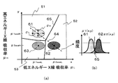
例えば、3つの組織61,62,63について識別マップを求める場合、それらについてX線吸収率分布μ1(x,y)、μ2(x,y)、μ3(x,y)を求め、それをxy平面に配置すると、図7(a)のようになる。X線吸収率分布μ1(x,y)、μ2(x,y)、μ3(x,y)は存在確率の変化を示す関数であるため、例えば、xy平面内の直線64における組織61,62のX線吸収率の頻度は、図7(b)のようにX線吸収率分布μ1(x,y)とμ2(x,y)が一部重なりあったグラフで表される。よって、組織61に対応する領域51と組織62に対応する領域52との境界65をどの位置に配置するかによって、組織61と組織62とを誤って識別する確率(誤答率)が求められる。したがって、全ての組織について誤答率が最も低くなる位置に境界65を引くことにより、最適な識別マップを作成することができる。
For example, when obtaining an identification map for three
X線吸収率分布から誤答率を演算する原理を説明する。図8(a)は、組織kのX線吸収率分布μk(x,y)220をxy平面上に示したものであり、図8(b)は、図8(a)の直線71上のμk(x,y)220の頻度を示したものである。境界線221を図8(a)、(b)のように設定した場合、組織kの正答率は、平均吸収率(μkaveL,μkaveH)222を含む領域Sk72に含まれるX線吸収率分布μk(x,y)の総和、すなわちμk(x,y)の領域72内の体積223によって表される。一方、組織kの誤答率は、領域Sk以外の領域73に含まれるX線吸収率分布μk(x,y)の総和、すなわちμk(x,y)の領域73内の体積224で表される。よって、誤答率は下記[数2]で表される。
識別マップに含まれる全ての組織に対する識別精度を評価するための全体誤答率Iは、各組織における誤答率の二乗和を組織数で規格化した下記[数3]で定義することができる。
全体誤答率Iを最小化するための境界を定める方法としては、種々の方法を用いることができる。例えば、第1の方法として、上述のステップ204(図4)で説明したように、識別マップのxy平面を微小領域(例えば画素)に分割し、微小領域(画素)の座標(x,y)における、各組織のX線吸収率分布μ1(x,y)、μ2(x,y)、μ3(x,y)・・・の頻度を比較し、最も頻度の大きいX線吸収率分布を選択し、選択したX線吸収率分布の組織(組成)を当該微小領域(画素)の組織(組成)として決定する方法を用いることができる。全ての微小領域(画素)について対応する組織を決定していくことにより、識別マップを生成することができる。この方法は、微小領域ごとに対応する組織を決定していくため、境界位置を決定するという計算を行う必要はなく、結果的に境界が定まる。このため、境界位置を定め、その位置による全体誤答率Iを計算しなくても、全体誤答率Iが最小になる識別マップを決定でき、計算量が少なくなるという利点がある。 Various methods can be used as a method for determining the boundary for minimizing the overall error rate I. For example, as the first method, as described in step 204 (FIG. 4), the xy plane of the identification map is divided into minute areas (for example, pixels), and the coordinates (x, y) of the minute area (pixels). , X-ray absorption rate distributions μ 1 (x, y), μ 2 (x, y), μ 3 (x, y)... A method of selecting a distribution and determining the tissue (composition) of the selected X-ray absorption rate distribution as the tissue (composition) of the microregion (pixel) can be used. An identification map can be generated by determining the corresponding tissue for all the minute regions (pixels). In this method, since the corresponding tissue is determined for each minute region, it is not necessary to perform calculation for determining the boundary position, and as a result, the boundary is determined. For this reason, it is possible to determine an identification map that minimizes the overall error rate I without determining the boundary position and calculating the overall error rate I according to the position, and there is an advantage that the calculation amount is reduced.
第2の方法としては、識別マップ上の各組織のX線吸収率分布μ1(x,y)、μ2(x,y)、μ3(x,y)・・を2つずつ組み合わせ、それら相互に交差する位置、すなわち頻度が等しくなる位置に境界を描くことにより、識別マップを生成する方法を用いることができる。この方法も、全体誤答率Iを計算しなくても、全体誤答率Iが最小になる識別マップを決定できる。この方法は、後述する第2の実施の形態で、識別マップを決定する際に用いている。 As a second method, two tissue X-ray absorption distributions μ 1 (x, y), μ 2 (x, y), μ 3 (x, y). A method of generating an identification map can be used by drawing boundaries at positions where they intersect each other, that is, at positions where the frequencies are equal. This method can also determine an identification map that minimizes the overall error rate I without calculating the overall error rate I. This method is used when determining the identification map in the second embodiment described later.
第3の方法としては、任意の位置に境界を定め、その都度、全体誤答率Iを求め、全体誤答率Iが最小になる境界位置を試行錯誤的に定める方法を用いることも可能である。 As a third method, it is also possible to use a method in which a boundary is defined at an arbitrary position, the overall error rate I is obtained each time, and the boundary position where the overall error rate I is minimized is determined by trial and error. is there.
つぎに、本実施の形態において図4のステップ201〜204で作成された識別マップが最適化されたものであることを検証するために図9の構造のファントムを用いて撮影実験を行った。ファントムは、人体腹部を想定して、断面が楕円形状を有し、生体組織に近い吸収率を有するウレタン151で構成されている。ファントムの中央、および上方には、それぞれ骨152、造影血管150を模擬した円筒体を配置した。造影血管150は、水に造影剤を混ぜたものが充填されている。ここでは10種類の濃度のものを用意した。
Next, in order to verify that the identification map created in
撮影実験では、入力モードにおいて、設定された撮影条件により識別マップを生成した。つぎに、本撮影モードにおいて、2種類のエネルギーのX線を照射して、X線吸収率画像を撮影し、入力モードで生成した識別マップを用いて組織の識別を行った。撮影条件の管電圧EL、EHは、それぞれ80kV、140kVに設定した。 In the shooting experiment, an identification map was generated according to the set shooting conditions in the input mode. Next, in the main imaging mode, two types of energy X-rays were irradiated, an X-ray absorptivity image was captured, and tissue was identified using the identification map generated in the input mode. The tube voltages E L and E H of the imaging conditions were set to 80 kV and 140 kV, respectively.
撮影実験の入力モードにおいて、撮影条件より計算した識別マップ156を図10に示す。図10の識別マップ156は、x軸が低エネルギーX線吸収率、y軸が高エネルギーX線吸収率を表し、境界221によってウレタン154、骨155、造影血管153の領域に分割されていることがわかる。この識別マップ156を適用し、本撮影モードで撮影した実際の撮影データをウレタン151、骨152、造影血管150を識別し、下記[数4]を用いてウレタン151、骨152、造影血管150の3つ組織の全体誤答率Iresを評価した。その結果を図11に示す。
なお、上記[数4]の評価用全体誤答率Iresは、一つの組織kにおける評価用誤答率である上記[数5]の二乗和を組織数で規格化したものであり、Iresが小さいほど識別精度が高いことを示す。[数4]および[数5]においてpk、ckは、それぞれ識別画像における組織kの全画素数および正答した画素数である。 Note that the overall error rate I res for evaluation in [Equation 4] is obtained by normalizing the sum of squares of [Equation 5], which is the error rate for evaluation in one organization k, by the number of organizations. The smaller res is, the higher the identification accuracy is. In [Equation 4] and [Equation 5], p k and c k are the total number of pixels of the tissue k and the number of correctly answered pixels in the identification image, respectively.
図11に示したように、本実施の形態により最適な識別マップ156を適用した場合は、従来法の識別マップを適用した場合と比較して評価用全体誤答率Iresが低く、識別精度が向上することがわかる。なお、撮影実験は、実際に撮影した画像を用いる方法の他、シミュレーションで擬似的に作成した画像で行うことも可能である。
As shown in FIG. 11, when the
上述した第1の実施の形態では、操作者が入力する度に識別マップの作成を行っているが、予め用意した撮影条件の組合せに対して識別マップを生成しておき、生成した識別マップを組織パラメータ保存部112に格納しておく構成にすることもできる。これにより、識別マップ計算部111は、組織パラメータ保存部112を参照するだけで識別マップを取得できるため、演算を高速化できる利点がある。
In the first embodiment described above, an identification map is created every time an operator inputs, but an identification map is generated for a combination of imaging conditions prepared in advance, and the generated identification map is It can also be configured to be stored in the organization
なお、第1の実施の形態では、X線CT装置の構成の一例として、生体用のX線CT装置を示したが、爆発物検査や製品の非破壊検査等の用途を目的としたX線CT装置に本発明を適用可能であることは言うまでもない。また本実施の形態では、一例として公知の第3世代のマルチスライスX線CT装置の構成を示したが、公知の第1、第2、第4世代のX線CT装置にも適用でき、公知のシングルスライスX線CT装置やエレクトロンビームCTにも適用できる。 In the first embodiment, the X-ray CT apparatus for living bodies is shown as an example of the configuration of the X-ray CT apparatus. However, X-rays intended for uses such as explosives inspection and non-destructive inspection of products are used. Needless to say, the present invention can be applied to a CT apparatus. In the present embodiment, the configuration of a known third-generation multi-slice X-ray CT apparatus is shown as an example, but the present invention can also be applied to known first-, second-, and fourth-generation X-ray CT apparatuses. It can also be applied to single-slice X-ray CT apparatus and electron beam CT.
(第2の実施の形態)
第2の実施の形態のデュアルエネルギーX線CT装置について説明する。第2の実施の形態のX線CT装置の構成は、第1の実施の形態のX線CT装置と同じであるが、識別マップ作成部111の識別マップ生成時の動作が第1の実施の形態とは異なっている。
(Second Embodiment)
A dual energy X-ray CT apparatus according to a second embodiment will be described. The configuration of the X-ray CT apparatus of the second embodiment is the same as that of the X-ray CT apparatus of the first embodiment, but the operation of the identification
第1の実施の形態では、操作者が、撮影条件入力部101に識別すべき領域としてN個の組織を指定した場合には、識別マップ作成部111は、N個の組織に対応するN個の領域に分割された識別マップ(例えば図5)を作成する構成であった。しかしながら、組織のX線吸収率分布μ(x,y)が似ている組織がある場合等には、生成された識別マップを用いても、2つの組織間を識別する精度が低いことが生じ得る。このような場合に、生成した識別マップを用いても、識別精度を向上させることができない。
In the first embodiment, when the operator designates N organizations as areas to be identified in the imaging
そこで、本実施の形態では、2つの組織間を識別する精度が閾値よりも低い場合、2つの組織は同じ組織として、識別マップ上の2つの組織に対応する領域を結合させるクラスタ化を行う。これにより、識別精度を向上させる。 Therefore, in the present embodiment, when the accuracy of discriminating between the two organizations is lower than the threshold value, the two organizations are regarded as the same organization, and clustering is performed to combine regions corresponding to the two organizations on the identification map. Thereby, the identification accuracy is improved.
例えば、図12のように、組織Aに対応する領域160と、組織Bに対応する領域161と、組織Cに対応する領域162が設定される識別マップにおいて、組織Aと組織Bとの識別精度が閾値よりも低い場合、両者をクラスタ化する情報164を生成し、組織A160と組織B161を組織AB163としてクラスタ化し、これにより識別マップ231を生成する。
For example, as shown in FIG. 12, in the identification map in which the area 160 corresponding to the organization A, the
以下、第2の実施の形態の識別マップ作成部111のマップ生成手順について、図13のフローチャートのステップ240〜244を用いて説明する。まず、第1の実施の形態の図4のステップ201〜203を行い、操作者が入力したN個の組織についてX線吸収率μ(x,y)をそれぞれ求める。
Hereinafter, the map generation procedure of the identification
つぎに、識別マップ上の各組織の境界を決定する。ここでは、各組織のX線吸収率分布μ1(x,y)、μ2(x,y)、μ3(x,y)・・を2つずつ組み合わせ、それら相互に交差する位置、すなわち頻度が等しくなる位置に境界を描く手法を用いる。具体的には、識別対象部位の組織kを選択し、組織k以外の組織i(i=1、2、…、N;k≠i)とのペアをそれぞれ作成し、各ペアごとに両者のX線吸収率分布が等しくなる位置に、識別マップ上に境界線を描く。(ステップ240)。例えば、図14(a)に示すように、組織k260と組織A261をペアとし、図14(d)に示すように2つの組織のX線吸収率分布μ(x,y)が交差する谷の位置を探索し、この位置に境界線263を描く。このとき、このペア以外他の組織のX線吸収率分布を考慮しない。
Next, the boundaries of each tissue on the identification map are determined. Here, X-ray absorption rate distributions μ 1 (x, y), μ 2 (x, y), μ 3 (x, y),. A method of drawing a boundary at a position where the frequencies are equal is used. Specifically, the tissue k of the part to be identified is selected, and a pair with a tissue i other than the tissue k (i = 1, 2,..., N; k ≠ i) is created. A boundary line is drawn on the identification map at a position where the X-ray absorption rate distributions are equal. (Step 240). For example, as shown in FIG. 14A, the tissue k260 and the tissue A261 are paired, and the X-ray absorption distribution μ (x, y) of the two tissues intersects as shown in FIG. 14D. A position is searched, and a
つぎに、上述の[数3]により、ペアにした2つ組織kおよびAについて全体誤答率Iを計算し(ステップ241)、予め定めた閾値と比較する(ステップ242)。計算した全体誤答率Iが閾値以上であれば、組織k、Aの識別精度が低いことを意味するので、後でクラスタ化する必要があると判断して、この組織ペアをメモリ123等に保存する(ステップ164)。
Next, the overall error rate I is calculated for the two organizations k and A paired by the above [Equation 3] (step 241), and compared with a predetermined threshold value (step 242). If the calculated total error rate I is equal to or greater than the threshold value, it means that the identification accuracy of the organizations k and A is low. Therefore, it is determined that clustering is necessary later, and this organization pair is stored in the
同様に、図14(b)のように、組織k260と別の組織B262のペアについても、境界線263を決定する(ステップ240)。組織k260と組織B262のペアについて全体誤答率Iを計算し、クラスタ化が必要かどうか判断し、必要であればメモリ123等に保存する(ステップ241、242、164)。これらの処理を、組織kと他の全ての組織との組合せについて行う。
Similarly, as shown in FIG. 14B, a
つぎに、図14(c)のように、組織k260と他の組織(組織A261および組織B262)の境界線263の積集合(AND)をとり、これを組織k260の最適な境界線263として決定する(ステップ243)。図14(c)では、AND処理により決定した境界線を実線264で示し、除外した境界線を破線265で示す。これにより、組織kの周囲の境界線264が決定できる。このように、組織ごとに境界線264を決定していく方法は、組織数を増加しても、生体組織の任意の組み合わせに対して境界を高速に計算できる。
Next, as shown in FIG. 14C, the product set (AND) of the
上記ステップ240〜243、164を全組織について順次行うことにより、各組織の周囲の境界線が決定され、識別マップが生成される。
By sequentially performing the
生成された識別マップの各組織の境界から、ステップ164において、メモリ123等にクラスタペアとして保存された組織ペア間の境界を図12のように消去し、両組織ペアを一つの組織とする(ステップ244)。これにより、識別精度の低い組織のクラスタ化を行うことができ、識別精度が向上された識別マップを生成することができる。
In
第2の実施の形態では、識別精度の低い2つの組織を1組織としてクラスタ化した識別マップを生成するため、この識別マップを用いて本撮影モードで組織の識別を行うことにより、全体誤答率Iを低下させることができ、識別精度が向上する。 In the second embodiment, in order to generate an identification map in which two organizations with low identification accuracy are clustered as one organization, using this identification map, the organization is identified in the main photographing mode. The rate I can be reduced, and the identification accuracy is improved.
なお、ステップ244では、閾値を用いてクラスタ化の必要性について判断する構成について説明したが、操作者が任意の組織間のクラスタ化を希望する場合、それをステップ201で受け付け、ステップ244においてクラスタペアとして保存することにより、クラスタ化することも可能である。
In
(第3の実施の形態)
第3の実施の形態のデュアルエネルギーCT装置では、最適なX線条件での撮像を可能にする。
第3の実施の形態のCT装置では、操作者が識別対象部位、組織、線量等の撮影条件をすべて入力する必要はなく、一部のみについて入力する。操作者が指定していない撮影条件については、X線CT装置が、複数種類に条件の異なる複数の候補値を作成し、それらの候補値ごとに識別マップを作成し、識別精度を求める。これにより、操作者が所望する撮影条件を満たしながら、識別精度が最も高い最適なX線条件を算出することができる。本撮影モードでは、算出した最適なX線条件で撮影を行うことができる。
(Third embodiment)
The dual energy CT apparatus according to the third embodiment enables imaging under optimal X-ray conditions.
In the CT apparatus according to the third embodiment, it is not necessary for the operator to input all imaging conditions such as the identification target region, tissue, and dose, but only a part of the imaging conditions. For imaging conditions not specified by the operator, the X-ray CT apparatus creates a plurality of candidate values having different conditions for a plurality of types, creates an identification map for each candidate value, and obtains identification accuracy. Accordingly, it is possible to calculate the optimum X-ray condition with the highest identification accuracy while satisfying the imaging condition desired by the operator. In this imaging mode, imaging can be performed under the calculated optimal X-ray condition.
第3の実施の形態のデュアルエネルギーX線CT装置の構造は、第1の実施の形態の図1の装置と同様の構成であるが、図15に示したように、入力手段101には、最適なX線条件を算出および表示するため、X線条件算出部170およびX線条件表示部171を備えている点が図1の装置とは異なっている。X線条件算出部170には、管電流量パラメータ保存部172が配置されている。他の構成は、図1と同じであるので説明を省略する。これらを実現するハードウエア構成としては、第1の実施の形態の図2の中央処理装置122によりメモリ123に予め格納しておいた所定のX線条件算出処理動作プログラムを展開・起動することによりX線条件算出部170を実現することができる。管電流量パラメータ保存部172は、メモリ123により構成することができる。X線条件表示部171は、画像生成手段103のモニタ129により兼用できる。
The structure of the dual energy X-ray CT apparatus of the third embodiment is the same as that of the apparatus of FIG. 1 of the first embodiment. However, as shown in FIG. 1 is different from the apparatus of FIG. 1 in that an X-ray
以下、第3の実施の形態のデュアルエネルギーX線CT装置の動作を説明する。本X線CT装置は、第1の実施の形態と同様に、入力モードと本撮影モードが用意されている。入力モードについて図16のフローチャートを用いて以下説明する。 The operation of the dual energy X-ray CT apparatus according to the third embodiment will be described below. As in the first embodiment, the X-ray CT apparatus is provided with an input mode and a main imaging mode. The input mode will be described below with reference to the flowchart of FIG.
(1)撮影条件設定
X線条件算出部170は、図17に示すような撮影条件入力のための画面をモニタ129に表示させる。この画面は、撮影条件として、識別対象部位選択リスト130、識別組織選択リスト131、線量モード180の3つについて設定を受け付ける画面である。操作者はマウス121やキーボード120等を用いて、これら撮影条件を設定する(図16のステップ270)。
(1) Imaging Condition Setting The X-ray
本実施の形態では、特に、X線条件を、管電圧および管電流量ではなく線量で設定することを可能にするため、線量モード180での設定を可能にしている。識別対象部位選択リスト130、識別組織選択リスト131における設定は、第1の実施の形態と同じであるので説明を省略する。線量モード180では、低被曝モードと高画質モードの2つのうち一方の選択を操作者から受け付ける。低被曝モードは、DE法ではない1種類のエネルギースペクトルを有するX線による撮影を行う通常撮影と同等の線量で、DE法を行うためのモードである。一方、高画質モードは、通常撮影より多い線量を用いてDE法を行うことにより、高SN画像を取得するためのモードである。これら低被曝モードおよび高画質モードには、それぞれ予め定められた線量値Rtotalが割り当てられている。よって、操作者は、線量の値を数値として入力することなく、線量を選択することができる。
In the present embodiment, in particular, the X-ray condition can be set not by the tube voltage and the tube current amount but by the dose, so that the setting in the
なお、線量モード180の設定方法は、この設定方法に限られるものではなく、数値入力欄を画面に表示し、操作者が線量を数値として入力する構成にすることも可能である。ここでいう線量とは、照射線量、被曝線量等を含むものとする。図17に示した画面は、識別対象部位、組織および線量の3つが、少なくとも設定できる構成であればよく、他の構成にすることも可能である。また、事前に撮影条件を保存した場合、毎回操作者が入力しなくてもよい。
The setting method of the
(2)最適X線条件の算出
次に、X線条件算出部170は、ステップ270で入力された識別対象部位、組織、線量モード180の撮影条件に基づき、この撮影条件を満たすX線条件(高エネルギーX線と低エネルギーX線の線量比、そのときの管電圧、管電流量)の複数の組合せ(候補値)を求める(図16のステップ271〜273)。
(2) Calculation of Optimum X-ray Conditions Next, the X-ray
まず、線量の分割を行い、線量の候補値を複数求める(ステップ271)。撮影条件入力部110が操作者から入力を受け付けた低被曝モードまたは高画質モードには、予め定めた数値の線量Rtotalが対応している。線量Rtotalは、低エネルギーX線および高エネルギーX線の線量の和であるので、X線条件算出部170は、選択されたモードの線量Rtotalを、低エネルギーX線と高エネルギーX線に対応するX線の線量RL、RHに分割する。分割方法としては、例えば予め定めておいた複数種類の分割比に線量Rtotalを掛ける方法を用いることができる。
First, doses are divided and a plurality of dose candidate values are obtained (step 271). A predetermined numerical dose R total corresponds to the low exposure mode or the high image quality mode in which the imaging
次に低エネルギーX線照射時と高エネルギーX線照射時の管電圧EL、EHの候補値を複数設定する(ステップ272)。例えば、予め定めた最低電圧から予め定めた電圧値ずつ電圧値を増加させることにより、管電圧EL、EHを設定する方法や、予め定めた複数種類の管電圧を順次選択することにより、管電圧EL、EHを設定する方法を用いることができる。また、操作者が、撮影条件入力部110から複数種類の管電圧EL、EHの組み合わせを入力する構成にすることもできる。
Next, a plurality of candidate values for tube voltages E L and E H at the time of low energy X-ray irradiation and at the time of high energy X-ray irradiation are set (step 272). For example, by increasing the voltage value by a predetermined voltage value from a predetermined minimum voltage, a method of setting the tube voltages E L and E H or by sequentially selecting a plurality of predetermined tube voltages, A method of setting the tube voltages E L and E H can be used. Further, the operator can input a combination of a plurality of types of tube voltages E L and E H from the imaging
次に管電流量IL、IHの候補値を複数設定する(ステップ273)。X線条件算出部170内の管電流量パラメータ保存部172には、予め求めておいた、線量と管電圧の組み合わせに対応する管電流量が、テーブルとして格納されている。X線条件算出部170は、管電流量パラメータ保存部172にアクセスすることにより、ステップ270で入力された複数種類の管電圧EL、EHの候補値および複数種類の線量RL、RHの候補値の組み合わせ(EL、RL)、(EH、RH)に対応する管電流量IL、IHを、それぞれ読み出す。これにより、管電流量の候補値を複数設定する。
Next, a plurality of candidate values for the tube current amounts I L and I H are set (step 273). In the tube current amount
識別マップ作成部111は、これら複数の候補値の組み合わせごとに識別マップを計算する(ステップ274)。識別マップの計算工程は、第1の実施の形態の図4のステップ201〜204と同様である。作成した識別マップごとに、第1の実施の形態で示した[数3]を用いて、マップ用全体誤答率Iを計算する(ステップ275)。計算したマップ用全体誤答率Iのうち最小のI値が得られた識別マップを選択し、その識別マップの計算に用いた候補値の組み合わせ(EL、RL、IL)、(EH、RH、IH)を、最適なX線条件として決定する(ステップ276)。以上より、操作者による任意の設定に対して、常に最適な識別マップおよび最適なX線条件を算出できる。
The identification
X線条件算出部、上述のステップ276で決定した最適なX線条件(EL、RL、IL)、(EH、RH、IH)と全体誤答率Iを、X線条件表示部171に表示する。操作者がこのX線条件での撮影を行うことを指示した場合には、この最適なX線条件での撮影が、本撮影モードで開始される。また、ステップ276で決定した最適なX線条件の全体誤答率Iが、操作者が予め定めておいた閾値以下である場合には、操作者からの指示を待つことなく、自動で本撮影モードを開始し、撮影を行う構成にすることも可能である。全体誤答率Iが上記閾値を超えている場合、例えば、X線条件表示部171にX線の照射不可を表示してもよい。
The X-ray condition calculation unit, the optimal X-ray conditions (E L , R L , I L ), (E H , R H , I H ) determined in the
撮影によって生成されたCT画像は、全体誤答率Iが最小な識別マップを用いて組織の識別画像を作成することができる。 A CT image generated by imaging can create an identification image of a tissue using an identification map with a minimum overall error rate I.
このように、第3の実施の形態のCT装置は、操作者がすべてのX線条件のパラメータを入力する必要はなく、高エネルギーX線と低エネルギーX線の線量比、および、それぞれの管電圧、管電流量については、操作者が入力した撮影条件を満たす候補値の中から、識別マップの全体誤答率Iが最小となる最適値を計算によって、求め、操作者に提示することができる。よって、全体誤答率Iが最小となるX線条件で撮影を行うことができ、全体誤答率Iが最小の識別マップで組織の識別を行うことができる。これにより、識別の高精度化、および線量の低減を実現できる。 Thus, the CT apparatus of the third embodiment does not require the operator to input all X-ray condition parameters, and the dose ratio of high energy X-rays and low energy X-rays and the respective tubes. Regarding the voltage and tube current amount, an optimum value that minimizes the overall error rate I of the identification map can be obtained by calculation from candidate values that satisfy the photographing conditions input by the operator, and can be presented to the operator. it can. Therefore, imaging can be performed under an X-ray condition that minimizes the overall error rate I, and tissue identification can be performed using an identification map that minimizes the overall error rate I. Thereby, high accuracy of identification and reduction of dose can be realized.
本実施の形態において、最適なX線条件が決定されているかどうかを検証するために撮影実験を行った。撮影実験には、第1の実施の形態における図9と同様のファントムを用いた。また、ステップ272において管電圧EL、EHの候補値の設定方法としては、予め定めた3種類の管電圧(80kV、120kV、140kV)の中から2種類の管電圧をEL、EHとして選択することにより設定した。なお、管電圧の候補値は、これらの値に限られるものではない。
In the present embodiment, an imaging experiment was performed in order to verify whether or not the optimum X-ray condition was determined. In the shooting experiment, the same phantom as in FIG. 9 in the first embodiment was used. In addition, as a method of setting candidate values of the tube voltages E L and E H in
ステップ270で設定される線量モード180は、低被曝モードを選択した。これにより、DE法ではない1種類のエネルギースペクトルを有するX線による通常撮影と同等の線量にRtotalを設定した。ステップ271で設定する低エネルギーX線と高エネルギーX線の線量比は、図18の横軸に示したように、合計線量Rtotalにおける低管電圧の線量比を0から1の間で変化させた。これにより、複数の識別マップを計算し、計算した識別マップに対して、上述の[数4]の評価用全体誤答率Iresを計算した。
As the
線量比(合計線量における低管電圧の線量)を変化させたときの全体誤答率Iresの変化を示すグラフを図18に示す。図18のように、各管電圧の組み合わせとも、線量比を変化させた場合の全体誤答率Iの変化を示すグラフが極小値を示し、図18の例では、管電圧EL80kVおよびEH140kVで線量比(合計線量における低管電圧の線量)が0.45のプロット280において評価用全体誤答率Iresが最小となった。これにより、プロット280の線量比、管電圧を最適なX線条件として算出できることが確認できた。
FIG. 18 shows a graph showing changes in the overall error rate I res when the dose ratio (dose of the low tube voltage in the total dose) is changed. As shown in FIG. 18, for each combination of tube voltages, a graph showing a change in the overall error rate I when the dose ratio is changed shows a minimum value. In the example of FIG. 18, the
なお、図18にグラフをプロットする場合、任意のサンプリング間隔の線量比について評価用全体誤答率Iresをそれぞれ求めてプロットし、近似曲線を用いてプロット間を補間することでIresの最小値を高速に算出することも可能である。 When plotting the graph in FIG. 18, the total error rate I res for evaluation is obtained for each dose ratio at an arbitrary sampling interval and plotted, and the minimum of I res is obtained by interpolating between the plots using an approximate curve. It is also possible to calculate the value at high speed.
上述してきたように、第3の実施の形態のデュアルエネルギーX線CT装置は、操作者が指定した線量に応じて、全体誤答率が最小になるX線条件を算出し、その条件で本撮影を行うことができるため、線量を低減したX線条件で、高精度な識別画像をDE法により取得できる。また、操作者に最適なX線条件を表示し、操作者が所望する条件で撮影を行うことも可能である。 As described above, the dual energy X-ray CT apparatus according to the third embodiment calculates an X-ray condition that minimizes the overall error rate in accordance with the dose specified by the operator, and this condition is used for this condition. Since imaging can be performed, a highly accurate identification image can be acquired by the DE method under X-ray conditions with a reduced dose. It is also possible to display the optimum X-ray conditions for the operator and perform imaging under conditions desired by the operator.
ここでは、照射線量を操作者が設定する構成について説明したが、照射線量に限らず、被写体の合計被曝量を設定する構成にすることも可能である。 Here, the configuration in which the operator sets the irradiation dose has been described. However, the configuration is not limited to the irradiation dose, and a configuration in which the total exposure amount of the subject is set is also possible.
上述の第3の実施の形態では、識別対象部位および合計線量を入力し、最適なX線条件(管電圧および管電流量)を算出したが、操作者から管電圧の入力を受け付けることにより、最適な管電流量のみを算出できることはいうまでもない。 In the third embodiment described above, the identification target region and the total dose are input and the optimum X-ray conditions (tube voltage and tube current amount) are calculated. By receiving the input of the tube voltage from the operator, Needless to say, only the optimum amount of tube current can be calculated.
なお、モンテカルロシミュレーションまたはエネルギースペクトルのデータベースを用いることにより、最適な管電圧および管電流量からエネルギースペクトルおよび合計フォトン数を計算できる。そのため最適な管電圧および管電流量の算出の代わりに、エネルギースペクトルおよび合計フォトン数を算出することも可能である。 By using a Monte Carlo simulation or an energy spectrum database, the energy spectrum and the total photon number can be calculated from the optimum tube voltage and tube current amount. Therefore, instead of calculating the optimum tube voltage and tube current amount, it is also possible to calculate the energy spectrum and the total number of photons.
第3の実施の形態では、操作者が入力する度に、X線条件の候補値を求め、識別マップの計算を行っているが、予め用意した撮影条件の組合せに対して識別マップを作成し、組織パラメータ保存部112に格納しておいても良い。これにより、識別マップ作成部111において組織パラメータ保存部112を参照するだけで識別マップを取得できるため、演算を高速化できる利点がある。
In the third embodiment, each time an operator inputs, X-ray condition candidate values are obtained and an identification map is calculated. An identification map is created for a combination of imaging conditions prepared in advance. Alternatively, it may be stored in the organization
第3の実施の形態では、一例として生体用のX線CT装置を示したが、爆発物検査や製品の非破壊検査等の用途を目的としたX線CT装置に本発明を適用しても良いことは言うまでもない。また本実施例は一例として公知の第3世代のマルチスライスX線CT装置を示したが、公知の第1、第2、第4世代のX線CT装置にも適用でき、公知のシングルスライスX線CT装置やエレクトロンビームCTにも適用できる。 In the third embodiment, a biological X-ray CT apparatus is shown as an example. However, the present invention can be applied to an X-ray CT apparatus for purposes such as explosives inspection and non-destructive inspection of products. It goes without saying that it is good. This embodiment shows a known third-generation multi-slice X-ray CT apparatus as an example, but can also be applied to known first-, second-, and fourth-generation X-ray CT apparatuses. It can also be applied to a line CT apparatus and an electron beam CT.
本発明では、第1および第2の実施の形態のように、識別対象部位、管電圧等の撮影条件に基づき、最適な識別マップを作成することができる。よって、最適な識別マップを適用することで識別の高精度化を図ることができる。また、第3の実施の形態のように、最適なX線条件を算出することも可能であるため、線量の低減を実現できる。 In the present invention, as in the first and second embodiments, an optimal identification map can be created based on the imaging conditions such as the identification target region and the tube voltage. Therefore, it is possible to increase the accuracy of identification by applying an optimal identification map. In addition, since the optimum X-ray condition can be calculated as in the third embodiment, the dose can be reduced.
1…X線発生部、2…X線検出部、3…X線管、4…X線検出器、5…ガントリー、6…回転板、7…テーブル、8…被写体、9…円形の開口部、101…入力手段、102…撮影手段、103…画像生成手段、110…撮影条件入力部、111…識別マップ作成部、112…組織パラメータ保存部、113…撮影制御部、114…信号収集部、115…再構成処理部、116…識別処理部、117…画像表示部、120…キーボード、121…マウス、122…中央処理装置、123…メモリ、124…HDD装置、125…ガントリー制御部、126…X線制御部、127…テーブル制御器、128…DAS、129…モニタ、130…識別部位選択リスト、131…識別組織選択リスト、132…X線条件入力領域、140…組織テーブル、141…組織テーブル(骨組織)、142…組織テーブル(造影血管組織)、150…造影血管、151…ウレタン、152…骨、153…造影血管領域、154…ウレタン領域、155…骨領域、156…識別マップ、160…組織Aの領域、161…組織Bの領域、162…組織Cの領域、163…組織AB、164…クラスタペア保存部、170…X線条件算出部、171…X線条件表示部、172…管電流量パラメータ保存部、180…線量モード
DESCRIPTION OF
Claims (14)
前記識別マップ作成部は、前記入力部に入力された前記X線照射条件における前記組成の存在確率の変化を示す関数を前記複数種類のX線吸収率を変数として前記組成ごとに求め、前記複数種類のX線吸収率をそれぞれ座標軸とする識別マップ空間に、前記組成ごとの前記存在確率の変化を示す関数が交差する位置を境界として描くことにより、前記境界によって隔てられた複数の領域が複数の前記組成にそれぞれ対応する前記識別マップを作成することを特徴とするX線CT装置。 An X-ray generation unit that generates X-rays having a plurality of different energy spectra, an X-ray detection unit that detects the X-rays after passing through a subject, and the plurality of types of X-rays based on detection signals of the X-ray detection unit An image calculation unit that calculates an X-ray absorptance image for each line; and values of X-ray absorptance in corresponding regions of the plurality of types of X-ray absorptivity images; Applying to an identification map indicating a relationship with the composition, an identification calculation unit for identifying the composition of the region, an identification map creating unit for creating the identification map, and a plurality of X-ray irradiation conditions of the X-ray generation unit to be identified An input unit that receives input from the operator with the composition of
The identification map creation unit obtains a function indicating a change in the existence probability of the composition under the X-ray irradiation conditions input to the input unit for each composition using the plurality of types of X-ray absorption rates as variables, and A plurality of regions separated by the boundary are obtained by drawing, as a boundary, a position where the function indicating the change in the existence probability for each composition intersects in an identification map space having each type of X-ray absorption rate as a coordinate axis. An X-ray CT apparatus that creates the identification map corresponding to each of the compositions.
前記識別マップ作成部は、前記入力部に入力された前記X線照射条件における前記組成の存在確率の変化を示す関数を前記複数種類のX線吸収率を変数として前記組成ごとに求め、前記複数種類のX線吸収率をそれぞれ座標軸とする識別マップ空間において、前記存在確率の変化を示す関数に基づき、所定の位置に境界を描くことにより、前記境界によって隔てられた複数の領域が複数の前記組成にそれぞれ対応する前記識別マップを作成することを特徴とするX線CT装置。 An X-ray generation unit that generates X-rays having a plurality of different energy spectra, an X-ray detection unit that detects the X-rays after passing through a subject, and the plurality of types of X-rays based on detection signals of the X-ray detection unit An image calculation unit that calculates an X-ray absorptance image for each line; and values of X-ray absorptance in corresponding regions of the plurality of types of X-ray absorptivity images; Applying to an identification map indicating a relationship with the composition, an identification calculation unit for identifying the composition of the region, an identification map creating unit for creating the identification map, and a plurality of X-ray irradiation conditions of the X-ray generation unit to be identified An input unit that receives input from the operator with the composition of
The identification map creation unit obtains a function indicating a change in the existence probability of the composition under the X-ray irradiation conditions input to the input unit for each composition using the plurality of types of X-ray absorption rates as variables, and In the identification map space with each type of X-ray absorption rate as a coordinate axis, a plurality of regions separated by the boundary are formed by drawing a boundary at a predetermined position based on the function indicating the change in the existence probability. An X-ray CT apparatus, wherein the identification map corresponding to each composition is created.
前記データ格納部には、前記入力部が受け付け可能な管電圧ごとの前記平均X線吸収率と、単位管電流量あたりの前記X線吸収率の標準偏差とが格納され、
前記識別マップ作成部は、前記単位管電流量あたりのX線吸収率の標準偏差と、前記入力部に設定された管電流量と、予め定めた数式とを用いて、前記X線吸収率の標準偏差を計算により求めることを特徴とするX線CT装置。 The X-ray CT apparatus according to claim 4 , wherein the input unit receives a setting of a tube voltage and a tube current amount for each of the plurality of types of X-rays as the X-ray irradiation condition.
The data storage unit stores the average X-ray absorption rate for each tube voltage that can be received by the input unit, and the standard deviation of the X-ray absorption rate per unit tube current amount,
The identification map creation unit uses the standard deviation of the X-ray absorption rate per unit tube current amount, the tube current amount set in the input unit, and a predetermined mathematical formula to calculate the X-ray absorption rate. An X-ray CT apparatus characterized by obtaining a standard deviation by calculation.
複数種類の異なるエネルギースペクトルを有するX線を被写体に照射し、前記被写体透過後の前記X線を検出し、検出した信号に基づき、前記複数種類のX線ごとにX線吸収率画像を計算する工程と、 A subject is irradiated with a plurality of types of X-rays having different energy spectra, the X-ray transmitted through the subject is detected, and an X-ray absorption image is calculated for each of the plurality of types of X-rays based on the detected signal. Process,
前記複数種類のX線吸収率画像の対応する領域におけるX線吸収率の値を、前記識別マップにあてはめ、前記領域の組成を識別する工程とを有するX線画像の組成識別方法であって、 Applying an X-ray absorption value in a corresponding region of the plurality of types of X-ray absorption images to the identification map, and identifying the composition of the region, comprising:
前記識別マップを作成する工程は、 The step of creating the identification map includes:
X線照射条件における組成の存在確率の変化を示す関数を複数種類のX線吸収率を変数として前記組成ごとに求め、前記複数種類のX線吸収率をそれぞれ座標軸とする識別マップ空間に、前記組成ごとの前記存在確率の変化を示す関数が交差する位置を境界として描くことにより、前記境界によって隔てられた複数の領域が複数の前記組成にそれぞれ対応する識別マップを作成する工程であることを特徴とするX線画像の組成識別方法。 A function indicating a change in the existence probability of the composition under X-ray irradiation conditions is obtained for each of the compositions using a plurality of types of X-ray absorption rates as variables, and the identification map space having the plurality of types of X-ray absorption rates as coordinate axes, A step of creating an identification map in which a plurality of regions separated by the boundary respectively correspond to a plurality of the compositions by drawing a position where the function indicating the change in the existence probability for each composition intersects as a boundary. A method for identifying a composition of a characteristic X-ray image.
複数種類の異なるエネルギースペクトルを有するX線を被写体に照射し、前記被写体透過後の前記X線を検出し、検出した信号に基づき、前記複数種類のX線ごとにX線吸収率画像を計算する工程と、 A subject is irradiated with a plurality of types of X-rays having different energy spectra, the X-ray transmitted through the subject is detected, and an X-ray absorption image is calculated for each of the plurality of types of X-rays based on the detected signal. Process,
前記複数種類のX線吸収率画像の対応する領域におけるX線吸収率の値を、前記識別マップにあてはめ、前記領域の組成を識別する工程とを有するX線画像の組成識別方法であって、 Applying an X-ray absorption value in a corresponding region of the plurality of types of X-ray absorption images to the identification map, and identifying the composition of the region, comprising:
前記識別マップを作成する工程は、 The step of creating the identification map includes:
X線照射条件における組成の存在確率の変化を示す関数を前記複数種類のX線吸収率を変数として前記組成ごとに求め、前記複数種類のX線吸収率をそれぞれ座標軸とする識別マップ空間において、前記存在確率の変化を示す関数に基づき、所定の位置に境界を描くことにより、前記境界によって隔てられた複数の領域が複数の前記組成にそれぞれ対応する識別マップを作成する工程であることをX線画像の組成識別方法。 In the identification map space where the function indicating the change in the existence probability of the composition under the X-ray irradiation conditions is obtained for each of the compositions using the plurality of types of X-ray absorption rates as variables, and the plurality of types of X-ray absorption rates are coordinate axes, X is a step of creating an identification map in which a plurality of regions separated by the boundary respectively correspond to a plurality of the compositions by drawing a boundary at a predetermined position based on the function indicating the change in the existence probability. Method for identifying composition of line image.
Priority Applications (4)
| Application Number | Priority Date | Filing Date | Title |
|---|---|---|---|
| JP2007181725A JP5105589B2 (en) | 2007-07-11 | 2007-07-11 | X-ray CT system |
| CN200780053691XA CN101686824B (en) | 2007-07-11 | 2007-12-21 | X ray CT system |
| US12/668,244 US7924969B2 (en) | 2007-07-11 | 2007-12-21 | X ray CT system |
| PCT/JP2007/074695 WO2009008102A1 (en) | 2007-07-11 | 2007-12-21 | X ray ct system |
Applications Claiming Priority (1)
| Application Number | Priority Date | Filing Date | Title |
|---|---|---|---|
| JP2007181725A JP5105589B2 (en) | 2007-07-11 | 2007-07-11 | X-ray CT system |
Publications (2)
| Publication Number | Publication Date |
|---|---|
| JP2009017984A JP2009017984A (en) | 2009-01-29 |
| JP5105589B2 true JP5105589B2 (en) | 2012-12-26 |
Family
ID=40228297
Family Applications (1)
| Application Number | Title | Priority Date | Filing Date |
|---|---|---|---|
| JP2007181725A Active JP5105589B2 (en) | 2007-07-11 | 2007-07-11 | X-ray CT system |
Country Status (4)
| Country | Link |
|---|---|
| US (1) | US7924969B2 (en) |
| JP (1) | JP5105589B2 (en) |
| CN (1) | CN101686824B (en) |
| WO (1) | WO2009008102A1 (en) |
Families Citing this family (25)
| Publication number | Priority date | Publication date | Assignee | Title |
|---|---|---|---|---|
| US8553959B2 (en) * | 2008-03-21 | 2013-10-08 | General Electric Company | Method and apparatus for correcting multi-modality imaging data |
| JP5570733B2 (en) * | 2009-01-26 | 2014-08-13 | ジーイー・メディカル・システムズ・グローバル・テクノロジー・カンパニー・エルエルシー | X-ray CT system |
| JP4727737B2 (en) * | 2009-02-24 | 2011-07-20 | 三菱重工業株式会社 | Radiotherapy apparatus control apparatus and target part position measurement method |
| JP5590548B2 (en) * | 2010-02-03 | 2014-09-17 | 国立大学法人京都大学 | X-ray CT image processing method, X-ray CT program, and X-ray CT apparatus equipped with the program |
| JP5442530B2 (en) * | 2010-05-24 | 2014-03-12 | ジーイー・メディカル・システムズ・グローバル・テクノロジー・カンパニー・エルエルシー | Image processing apparatus, image display apparatus, program, and X-ray CT apparatus |
| JP5898081B2 (en) * | 2010-09-07 | 2016-04-06 | 株式会社日立メディコ | X-ray CT system |
| US20120166117A1 (en) * | 2010-10-29 | 2012-06-28 | Xia Llc | Method and apparatus for evaluating superconducting tunnel junction detector noise versus bias voltage |
| US8737567B2 (en) * | 2011-01-27 | 2014-05-27 | Medtronic Navigation, Inc. | Image acquisition optimization |
| JP6026145B2 (en) * | 2012-06-05 | 2016-11-16 | 東芝メディカルシステムズ株式会社 | X-ray CT system |
| WO2013188957A1 (en) * | 2012-06-18 | 2013-12-27 | University Health Network | Method and system for compressed sensing image reconstruction |
| US9354185B2 (en) * | 2012-12-21 | 2016-05-31 | Advanced Micro Devices, Inc. | 3D imaging with multiple irradiation frequencies |
| US10451568B2 (en) | 2014-08-22 | 2019-10-22 | Canon Medical Systems Corporation | Photon counting X-ray CT apparatus |
| WO2016039054A1 (en) * | 2014-09-11 | 2016-03-17 | 株式会社日立メディコ | Photon counting ct device and estimated exposure level computation method |
| US10117628B2 (en) * | 2014-10-01 | 2018-11-06 | Toshiba Medical Systems Corporation | Photon counting apparatus |
| US9964499B2 (en) * | 2014-11-04 | 2018-05-08 | Toshiba Medical Systems Corporation | Method of, and apparatus for, material classification in multi-energy image data |
| US10213172B2 (en) | 2015-02-20 | 2019-02-26 | General Electric Company | Imaging method and system of tube voltage and current optimization |
| WO2016171186A1 (en) * | 2015-04-20 | 2016-10-27 | 株式会社ジョブ | Data processing device and data processing method for x-ray examination, and x-ray examination apparatus provided with said device |
| CN108135558B (en) * | 2015-10-05 | 2021-09-03 | 皇家飞利浦有限公司 | Device for characterizing a body part |
| CN105911075B (en) * | 2016-05-23 | 2019-07-16 | 奕瑞影像科技(太仓)有限公司 | A kind of test method and system of X-ray accumulation large dosage |
| CN108811488B (en) * | 2017-02-27 | 2022-05-03 | 纳米维景(上海)医疗科技有限公司 | Static real-time CT imaging system and method adapting to large-field-of-view requirement |
| JP7161212B2 (en) | 2017-05-16 | 2022-10-26 | 株式会社ジョブ | Data processing device and data processing method in X-ray inspection, and X-ray inspection device equipped with the device |
| US10813205B2 (en) * | 2018-01-12 | 2020-10-20 | Accuray Incorporated | Detecting motion by using a low dose x-ray image |
| US11246559B2 (en) * | 2019-02-14 | 2022-02-15 | Prismatic Sensors Ab | Calibration of an x-ray imaging system |
| CN110192885A (en) * | 2019-05-30 | 2019-09-03 | 上海联影医疗科技有限公司 | Dosing method, device, equipment and storage medium based on X-ray imaging |
| JP2024155060A (en) * | 2023-04-20 | 2024-10-31 | Hoya株式会社 | X-ray CT device, program, and information processing method |
Family Cites Families (11)
| Publication number | Priority date | Publication date | Assignee | Title |
|---|---|---|---|---|
| US3965358A (en) * | 1974-12-06 | 1976-06-22 | Albert Macovski | Cross-sectional imaging system using a polychromatic x-ray source |
| US5187658A (en) * | 1990-01-17 | 1993-02-16 | General Electric Company | System and method for segmenting internal structures contained within the interior region of a solid object |
| US6922462B2 (en) | 2002-07-31 | 2005-07-26 | Ge Medical Systems Global Technology Company, Llc | Method, system and computer product for plaque characterization |
| JP3974842B2 (en) * | 2002-10-30 | 2007-09-12 | アロカ株式会社 | X-ray bone density measuring device |
| US6898263B2 (en) | 2002-11-27 | 2005-05-24 | Ge Medical Systems Global Technology Company, Llc | Method and apparatus for soft-tissue volume visualization |
| DE10311628B4 (en) | 2003-03-14 | 2006-04-13 | Siemens Ag | imaging |
| DE10347961A1 (en) | 2003-10-10 | 2005-06-09 | Schering Ag | X-ray arrangement and X-ray contrast method for imaging on an examination subject containing at least one X-ray contrast element and use of the X-ray arrangement |
| JP4794238B2 (en) * | 2005-08-10 | 2011-10-19 | 株式会社日立メディコ | Multi-energy X-ray CT system |
| DE102005037367B3 (en) | 2005-08-08 | 2007-04-05 | Siemens Ag | Method for an X-ray device |
| DE102005049602B3 (en) * | 2005-10-17 | 2007-04-19 | Siemens Ag | Segmenting at least one substance in an x-ray image involves determining number of image points in classification range as assessment value and deriving segmented image with threshold comparison based on assessment value |
| US7920669B2 (en) * | 2007-07-25 | 2011-04-05 | Siemens Aktiengesellschaft | Methods, apparatuses and computer readable mediums for generating images based on multi-energy computed tomography data |
-
2007
- 2007-07-11 JP JP2007181725A patent/JP5105589B2/en active Active
- 2007-12-21 US US12/668,244 patent/US7924969B2/en active Active
- 2007-12-21 CN CN200780053691XA patent/CN101686824B/en not_active Expired - Fee Related
- 2007-12-21 WO PCT/JP2007/074695 patent/WO2009008102A1/en active Application Filing
Also Published As
| Publication number | Publication date |
|---|---|
| WO2009008102A1 (en) | 2009-01-15 |
| JP2009017984A (en) | 2009-01-29 |
| CN101686824A (en) | 2010-03-31 |
| US20100226474A1 (en) | 2010-09-09 |
| US7924969B2 (en) | 2011-04-12 |
| CN101686824B (en) | 2012-11-28 |
Similar Documents
| Publication | Publication Date | Title |
|---|---|---|
| JP5105589B2 (en) | X-ray CT system | |
| JP5191787B2 (en) | X-ray CT system | |
| Seeram | Computed Tomography: Physics and Technology. A Self Assessment Guide | |
| US6904118B2 (en) | Method and apparatus for generating a density map using dual-energy CT | |
| JP5942266B2 (en) | X-ray CT apparatus and tube current determination method | |
| US7715522B2 (en) | X-ray CT apparatus | |
| JP5042465B2 (en) | Radiation imaging apparatus and image processing method | |
| JP4512609B2 (en) | Apparatus for optimizing irradiation dose in CT angiography of coronary artery using standard deviation of CT value | |
| US8649479B2 (en) | System and method for breast imaging using X-ray computed tomography | |
| JP5484788B2 (en) | X-ray CT system | |
| JP6329490B2 (en) | X-ray CT apparatus and image reconstruction method | |
| EP2433566A2 (en) | System and method for blood vessel stenosis visualization and quantification using spectral CT analysis | |
| JP5028528B2 (en) | X-ray CT system | |
| US20090052621A1 (en) | Method and apparatus for basis material decomposition with k-edge materials | |
| US8855385B2 (en) | Apparatus and method for multi-energy tissue quantification | |
| US20070053478A1 (en) | X-ray ct apparatus and x-ray radiographic method | |
| JP2004329661A (en) | X-ray computerized tomographic apparatus and image noise simulation apparatus | |
| JP2004174253A (en) | Method and device for visualization of soft tissue space | |
| WO2016117418A1 (en) | X-ray ct apparatus and imaging method | |
| EP2490593A2 (en) | Acquisition protocol assessment apparatus | |
| JP2005095397A (en) | Method of correcting scattered x-ray component, program therefor, and x-ray ct system | |
| Zainon | Spectral micro-ct imaging of ex vivo atherosclerotic plaque | |
| EP4201331A1 (en) | Dynamic perspective method, apparatus and system for c-shaped arm equipment | |
| JP2003033346A (en) | X-ray ct system and its control method | |
| JP6873831B2 (en) | Medical image diagnostic equipment, medical image processing equipment and medical image processing program |
Legal Events
| Date | Code | Title | Description |
|---|---|---|---|
| A621 | Written request for application examination |
Free format text: JAPANESE INTERMEDIATE CODE: A621 Effective date: 20100308 |
|
| A131 | Notification of reasons for refusal |
Free format text: JAPANESE INTERMEDIATE CODE: A131 Effective date: 20120124 |
|
| A521 | Request for written amendment filed |
Free format text: JAPANESE INTERMEDIATE CODE: A523 Effective date: 20120322 |
|
| TRDD | Decision of grant or rejection written | ||
| A01 | Written decision to grant a patent or to grant a registration (utility model) |
Free format text: JAPANESE INTERMEDIATE CODE: A01 Effective date: 20120904 |
|
| A01 | Written decision to grant a patent or to grant a registration (utility model) |
Free format text: JAPANESE INTERMEDIATE CODE: A01 |
|
| A61 | First payment of annual fees (during grant procedure) |
Free format text: JAPANESE INTERMEDIATE CODE: A61 Effective date: 20121001 |
|
| R150 | Certificate of patent or registration of utility model |
Ref document number: 5105589 Country of ref document: JP Free format text: JAPANESE INTERMEDIATE CODE: R150 Free format text: JAPANESE INTERMEDIATE CODE: R150 |
|
| FPAY | Renewal fee payment (event date is renewal date of database) |
Free format text: PAYMENT UNTIL: 20151012 Year of fee payment: 3 |
|
| S111 | Request for change of ownership or part of ownership |
Free format text: JAPANESE INTERMEDIATE CODE: R313111 |
|
| S533 | Written request for registration of change of name |
Free format text: JAPANESE INTERMEDIATE CODE: R313533 |
|
| R350 | Written notification of registration of transfer |
Free format text: JAPANESE INTERMEDIATE CODE: R350 |
|
| R250 | Receipt of annual fees |
Free format text: JAPANESE INTERMEDIATE CODE: R250 |
|
| S111 | Request for change of ownership or part of ownership |
Free format text: JAPANESE INTERMEDIATE CODE: R313111 |
|
| R350 | Written notification of registration of transfer |
Free format text: JAPANESE INTERMEDIATE CODE: R350 |
|
| R250 | Receipt of annual fees |
Free format text: JAPANESE INTERMEDIATE CODE: R250 |
|
| R250 | Receipt of annual fees |
Free format text: JAPANESE INTERMEDIATE CODE: R250 |
|
| S111 | Request for change of ownership or part of ownership |
Free format text: JAPANESE INTERMEDIATE CODE: R313111 |
|
| R350 | Written notification of registration of transfer |
Free format text: JAPANESE INTERMEDIATE CODE: R350 |
|
| R250 | Receipt of annual fees |
Free format text: JAPANESE INTERMEDIATE CODE: R250 |