JP5102201B2 - Removable embolic clot filter - Google Patents
Removable embolic clot filter Download PDFInfo
- Publication number
- JP5102201B2 JP5102201B2 JP2008511266A JP2008511266A JP5102201B2 JP 5102201 B2 JP5102201 B2 JP 5102201B2 JP 2008511266 A JP2008511266 A JP 2008511266A JP 2008511266 A JP2008511266 A JP 2008511266A JP 5102201 B2 JP5102201 B2 JP 5102201B2
- Authority
- JP
- Japan
- Prior art keywords
- longitudinal axis
- segment
- hub
- angle
- filter
- Prior art date
- Legal status (The legal status is an assumption and is not a legal conclusion. Google has not performed a legal analysis and makes no representation as to the accuracy of the status listed.)
- Active
Links
- 230000003073 embolic effect Effects 0.000 title 1
- 210000004204 blood vessel Anatomy 0.000 claims description 56
- 239000008280 blood Substances 0.000 claims description 31
- 210000004369 blood Anatomy 0.000 claims description 31
- 239000000463 material Substances 0.000 claims description 19
- 238000000034 method Methods 0.000 claims description 17
- 239000012867 bioactive agent Substances 0.000 claims description 6
- 230000000149 penetrating effect Effects 0.000 claims description 4
- 238000005452 bending Methods 0.000 claims description 2
- 230000008878 coupling Effects 0.000 claims 1
- 238000010168 coupling process Methods 0.000 claims 1
- 238000005859 coupling reaction Methods 0.000 claims 1
- 230000002401 inhibitory effect Effects 0.000 claims 1
- 238000004519 manufacturing process Methods 0.000 claims 1
- 210000003462 vein Anatomy 0.000 description 13
- 230000007704 transition Effects 0.000 description 10
- 230000003511 endothelial effect Effects 0.000 description 8
- 229910000734 martensite Inorganic materials 0.000 description 8
- 229910001000 nickel titanium Inorganic materials 0.000 description 8
- HLXZNVUGXRDIFK-UHFFFAOYSA-N nickel titanium Chemical compound [Ti].[Ti].[Ti].[Ti].[Ti].[Ti].[Ti].[Ti].[Ti].[Ti].[Ti].[Ni].[Ni].[Ni].[Ni].[Ni].[Ni].[Ni].[Ni].[Ni].[Ni].[Ni].[Ni].[Ni].[Ni] HLXZNVUGXRDIFK-UHFFFAOYSA-N 0.000 description 8
- 238000011084 recovery Methods 0.000 description 7
- 238000003466 welding Methods 0.000 description 7
- 229910052751 metal Inorganic materials 0.000 description 6
- 239000002184 metal Substances 0.000 description 6
- 230000017531 blood circulation Effects 0.000 description 5
- 230000006870 function Effects 0.000 description 5
- 239000012781 shape memory material Substances 0.000 description 5
- 210000001631 vena cava inferior Anatomy 0.000 description 5
- RJURFGZVJUQBHK-UHFFFAOYSA-N actinomycin D Natural products CC1OC(=O)C(C(C)C)N(C)C(=O)CN(C)C(=O)C2CCCN2C(=O)C(C(C)C)NC(=O)C1NC(=O)C1=C(N)C(=O)C(C)=C2OC(C(C)=CC=C3C(=O)NC4C(=O)NC(C(N5CCCC5C(=O)N(C)CC(=O)N(C)C(C(C)C)C(=O)OC4C)=O)C(C)C)=C3N=C21 RJURFGZVJUQBHK-UHFFFAOYSA-N 0.000 description 4
- 229910001566 austenite Inorganic materials 0.000 description 4
- 230000036760 body temperature Effects 0.000 description 4
- 230000006835 compression Effects 0.000 description 4
- 238000007906 compression Methods 0.000 description 4
- 238000013461 design Methods 0.000 description 4
- 229910000701 elgiloys (Co-Cr-Ni Alloy) Inorganic materials 0.000 description 4
- -1 for example Inorganic materials 0.000 description 4
- 239000003112 inhibitor Substances 0.000 description 4
- BASFCYQUMIYNBI-UHFFFAOYSA-N platinum Chemical compound [Pt] BASFCYQUMIYNBI-UHFFFAOYSA-N 0.000 description 4
- 208000005189 Embolism Diseases 0.000 description 3
- DCXYFEDJOCDNAF-REOHCLBHSA-N L-asparagine Chemical compound OC(=O)[C@@H](N)CC(N)=O DCXYFEDJOCDNAF-REOHCLBHSA-N 0.000 description 3
- 208000010378 Pulmonary Embolism Diseases 0.000 description 3
- 208000007536 Thrombosis Diseases 0.000 description 3
- 230000001028 anti-proliverative effect Effects 0.000 description 3
- 239000003795 chemical substances by application Substances 0.000 description 3
- 230000007423 decrease Effects 0.000 description 3
- 238000001914 filtration Methods 0.000 description 3
- 238000002513 implantation Methods 0.000 description 3
- 208000014674 injury Diseases 0.000 description 3
- 238000003780 insertion Methods 0.000 description 3
- 230000037431 insertion Effects 0.000 description 3
- 208000024891 symptom Diseases 0.000 description 3
- 230000008733 trauma Effects 0.000 description 3
- 230000002792 vascular Effects 0.000 description 3
- QTBSBXVTEAMEQO-UHFFFAOYSA-N Acetic acid Natural products CC(O)=O QTBSBXVTEAMEQO-UHFFFAOYSA-N 0.000 description 2
- BSYNRYMUTXBXSQ-UHFFFAOYSA-N Aspirin Chemical compound CC(=O)OC1=CC=CC=C1C(O)=O BSYNRYMUTXBXSQ-UHFFFAOYSA-N 0.000 description 2
- DLGOEMSEDOSKAD-UHFFFAOYSA-N Carmustine Chemical compound ClCCNC(=O)N(N=O)CCCl DLGOEMSEDOSKAD-UHFFFAOYSA-N 0.000 description 2
- PTOAARAWEBMLNO-KVQBGUIXSA-N Cladribine Chemical compound C1=NC=2C(N)=NC(Cl)=NC=2N1[C@H]1C[C@H](O)[C@@H](CO)O1 PTOAARAWEBMLNO-KVQBGUIXSA-N 0.000 description 2
- 108010092160 Dactinomycin Proteins 0.000 description 2
- AOJJSUZBOXZQNB-TZSSRYMLSA-N Doxorubicin Chemical compound O([C@H]1C[C@@](O)(CC=2C(O)=C3C(=O)C=4C=CC=C(C=4C(=O)C3=C(O)C=21)OC)C(=O)CO)[C@H]1C[C@H](N)[C@H](O)[C@H](C)O1 AOJJSUZBOXZQNB-TZSSRYMLSA-N 0.000 description 2
- 108050007372 Fibroblast Growth Factor Proteins 0.000 description 2
- 102000018233 Fibroblast Growth Factor Human genes 0.000 description 2
- HTTJABKRGRZYRN-UHFFFAOYSA-N Heparin Chemical compound OC1C(NC(=O)C)C(O)OC(COS(O)(=O)=O)C1OC1C(OS(O)(=O)=O)C(O)C(OC2C(C(OS(O)(=O)=O)C(OC3C(C(O)C(O)C(O3)C(O)=O)OS(O)(=O)=O)C(CO)O2)NS(O)(=O)=O)C(C(O)=O)O1 HTTJABKRGRZYRN-UHFFFAOYSA-N 0.000 description 2
- SIKJAQJRHWYJAI-UHFFFAOYSA-N Indole Chemical compound C1=CC=C2NC=CC2=C1 SIKJAQJRHWYJAI-UHFFFAOYSA-N 0.000 description 2
- FAPWRFPIFSIZLT-UHFFFAOYSA-M Sodium chloride Chemical compound [Na+].[Cl-] FAPWRFPIFSIZLT-UHFFFAOYSA-M 0.000 description 2
- 108010073929 Vascular Endothelial Growth Factor A Proteins 0.000 description 2
- 102000005789 Vascular Endothelial Growth Factors Human genes 0.000 description 2
- 108010019530 Vascular Endothelial Growth Factors Proteins 0.000 description 2
- 229960001138 acetylsalicylic acid Drugs 0.000 description 2
- 239000002253 acid Substances 0.000 description 2
- RJURFGZVJUQBHK-IIXSONLDSA-N actinomycin D Chemical compound C[C@H]1OC(=O)[C@H](C(C)C)N(C)C(=O)CN(C)C(=O)[C@@H]2CCCN2C(=O)[C@@H](C(C)C)NC(=O)[C@H]1NC(=O)C1=C(N)C(=O)C(C)=C2OC(C(C)=CC=C3C(=O)N[C@@H]4C(=O)N[C@@H](C(N5CCC[C@H]5C(=O)N(C)CC(=O)N(C)[C@@H](C(C)C)C(=O)O[C@@H]4C)=O)C(C)C)=C3N=C21 RJURFGZVJUQBHK-IIXSONLDSA-N 0.000 description 2
- RWZYAGGXGHYGMB-UHFFFAOYSA-N anthranilic acid Chemical compound NC1=CC=CC=C1C(O)=O RWZYAGGXGHYGMB-UHFFFAOYSA-N 0.000 description 2
- 230000002927 anti-mitotic effect Effects 0.000 description 2
- 239000002473 artificial blood Substances 0.000 description 2
- 229960001230 asparagine Drugs 0.000 description 2
- TZCXTZWJZNENPQ-UHFFFAOYSA-L barium sulfate Chemical compound [Ba+2].[O-]S([O-])(=O)=O TZCXTZWJZNENPQ-UHFFFAOYSA-L 0.000 description 2
- 238000005219 brazing Methods 0.000 description 2
- 239000002131 composite material Substances 0.000 description 2
- 150000001875 compounds Chemical class 0.000 description 2
- 229960000640 dactinomycin Drugs 0.000 description 2
- 229940126864 fibroblast growth factor Drugs 0.000 description 2
- JYGXADMDTFJGBT-VWUMJDOOSA-N hydrocortisone Chemical compound O=C1CC[C@]2(C)[C@H]3[C@@H](O)C[C@](C)([C@@](CC4)(O)C(=O)CO)[C@@H]4[C@@H]3CCC2=C1 JYGXADMDTFJGBT-VWUMJDOOSA-N 0.000 description 2
- CGIGDMFJXJATDK-UHFFFAOYSA-N indomethacin Chemical compound CC1=C(CC(O)=O)C2=CC(OC)=CC=C2N1C(=O)C1=CC=C(Cl)C=C1 CGIGDMFJXJATDK-UHFFFAOYSA-N 0.000 description 2
- 230000007246 mechanism Effects 0.000 description 2
- 229910001092 metal group alloy Inorganic materials 0.000 description 2
- 229910052697 platinum Inorganic materials 0.000 description 2
- ZAHRKKWIAAJSAO-UHFFFAOYSA-N rapamycin Natural products COCC(O)C(=C/C(C)C(=O)CC(OC(=O)C1CCCCN1C(=O)C(=O)C2(O)OC(CC(OC)C(=CC=CC=CC(C)CC(C)C(=O)C)C)CCC2C)C(C)CC3CCC(O)C(C3)OC)C ZAHRKKWIAAJSAO-UHFFFAOYSA-N 0.000 description 2
- 230000035945 sensitivity Effects 0.000 description 2
- 229910001285 shape-memory alloy Inorganic materials 0.000 description 2
- 229960002930 sirolimus Drugs 0.000 description 2
- QFJCIRLUMZQUOT-HPLJOQBZSA-N sirolimus Chemical compound C1C[C@@H](O)[C@H](OC)C[C@@H]1C[C@@H](C)[C@H]1OC(=O)[C@@H]2CCCCN2C(=O)C(=O)[C@](O)(O2)[C@H](C)CC[C@H]2C[C@H](OC)/C(C)=C/C=C/C=C/[C@@H](C)C[C@@H](C)C(=O)[C@H](OC)[C@H](O)/C(C)=C/[C@@H](C)C(=O)C1 QFJCIRLUMZQUOT-HPLJOQBZSA-N 0.000 description 2
- 239000011780 sodium chloride Substances 0.000 description 2
- 239000010935 stainless steel Substances 0.000 description 2
- 229910001220 stainless steel Inorganic materials 0.000 description 2
- 238000012360 testing method Methods 0.000 description 2
- WYWHKKSPHMUBEB-UHFFFAOYSA-N tioguanine Chemical compound N1C(N)=NC(=S)C2=C1N=CN2 WYWHKKSPHMUBEB-UHFFFAOYSA-N 0.000 description 2
- FPVKHBSQESCIEP-UHFFFAOYSA-N (8S)-3-(2-deoxy-beta-D-erythro-pentofuranosyl)-3,6,7,8-tetrahydroimidazo[4,5-d][1,3]diazepin-8-ol Natural products C1C(O)C(CO)OC1N1C(NC=NCC2O)=C2N=C1 FPVKHBSQESCIEP-UHFFFAOYSA-N 0.000 description 1
- FDKXTQMXEQVLRF-ZHACJKMWSA-N (E)-dacarbazine Chemical compound CN(C)\N=N\c1[nH]cnc1C(N)=O FDKXTQMXEQVLRF-ZHACJKMWSA-N 0.000 description 1
- 102100025573 1-alkyl-2-acetylglycerophosphocholine esterase Human genes 0.000 description 1
- VSNHCAURESNICA-NJFSPNSNSA-N 1-oxidanylurea Chemical compound N[14C](=O)NO VSNHCAURESNICA-NJFSPNSNSA-N 0.000 description 1
- FUFLCEKSBBHCMO-UHFFFAOYSA-N 11-dehydrocorticosterone Natural products O=C1CCC2(C)C3C(=O)CC(C)(C(CC4)C(=O)CO)C4C3CCC2=C1 FUFLCEKSBBHCMO-UHFFFAOYSA-N 0.000 description 1
- NYWSLZMTZNODJM-MCGDBQAWSA-N 2-[5-[(4e,20e)-35-butyl-19-[(2s,3s,4s,5r)-3,4-dihydroxy-5-(hydroxymethyl)oxolan-2-yl]oxy-10,12,14,16,18,22,26,30,34-nonahydroxy-3,5,21,33-tetramethyl-36-oxo-1-oxacyclohexatriaconta-4,20-dien-2-yl]-4-hydroxyhexyl]guanidine Chemical compound OC1CC(O)CC(O)CC(O)CC(O)CCCC\C(C)=C\C(C)C(C(C)C(O)CCCN=C(N)N)OC(=O)C(CCCC)C(O)C(C)CCC(O)CCCC(O)CCCC(O)\C(C)=C\C1O[C@@H]1[C@@H](O)[C@H](O)[C@@H](CO)O1 NYWSLZMTZNODJM-MCGDBQAWSA-N 0.000 description 1
- CTRPRMNBTVRDFH-UHFFFAOYSA-N 2-n-methyl-1,3,5-triazine-2,4,6-triamine Chemical compound CNC1=NC(N)=NC(N)=N1 CTRPRMNBTVRDFH-UHFFFAOYSA-N 0.000 description 1
- PLIKAWJENQZMHA-UHFFFAOYSA-N 4-aminophenol Chemical class NC1=CC=C(O)C=C1 PLIKAWJENQZMHA-UHFFFAOYSA-N 0.000 description 1
- VHRSUDSXCMQTMA-PJHHCJLFSA-N 6alpha-methylprednisolone Chemical compound C([C@@]12C)=CC(=O)C=C1[C@@H](C)C[C@@H]1[C@@H]2[C@@H](O)C[C@]2(C)[C@@](O)(C(=O)CO)CC[C@H]21 VHRSUDSXCMQTMA-PJHHCJLFSA-N 0.000 description 1
- STQGQHZAVUOBTE-UHFFFAOYSA-N 7-Cyan-hept-2t-en-4,6-diinsaeure Natural products C1=2C(O)=C3C(=O)C=4C(OC)=CC=CC=4C(=O)C3=C(O)C=2CC(O)(C(C)=O)CC1OC1CC(N)C(O)C(C)O1 STQGQHZAVUOBTE-UHFFFAOYSA-N 0.000 description 1
- RZVAJINKPMORJF-UHFFFAOYSA-N Acetaminophen Chemical compound CC(=O)NC1=CC=C(O)C=C1 RZVAJINKPMORJF-UHFFFAOYSA-N 0.000 description 1
- 108020000948 Antisense Oligonucleotides Proteins 0.000 description 1
- 108010024976 Asparaginase Proteins 0.000 description 1
- DCXYFEDJOCDNAF-UHFFFAOYSA-N Asparagine Natural products OC(=O)C(N)CC(N)=O DCXYFEDJOCDNAF-UHFFFAOYSA-N 0.000 description 1
- XHVAWZZCDCWGBK-WYRLRVFGSA-M Aurothioglucose Chemical compound OC[C@H]1O[C@H](S[Au])[C@H](O)[C@@H](O)[C@@H]1O XHVAWZZCDCWGBK-WYRLRVFGSA-M 0.000 description 1
- NOWKCMXCCJGMRR-UHFFFAOYSA-N Aziridine Chemical compound C1CN1 NOWKCMXCCJGMRR-UHFFFAOYSA-N 0.000 description 1
- 239000005552 B01AC04 - Clopidogrel Substances 0.000 description 1
- 239000005528 B01AC05 - Ticlopidine Substances 0.000 description 1
- 108010006654 Bleomycin Proteins 0.000 description 1
- 229940123587 Cell cycle inhibitor Drugs 0.000 description 1
- JWBOIMRXGHLCPP-UHFFFAOYSA-N Chloditan Chemical compound C=1C=CC=C(Cl)C=1C(C(Cl)Cl)C1=CC=C(Cl)C=C1 JWBOIMRXGHLCPP-UHFFFAOYSA-N 0.000 description 1
- MFYSYFVPBJMHGN-UHFFFAOYSA-N Cortisone Natural products O=C1CCC2(C)C3C(=O)CC(C)(C(CC4)(O)C(=O)CO)C4C3CCC2=C1 MFYSYFVPBJMHGN-UHFFFAOYSA-N 0.000 description 1
- MFYSYFVPBJMHGN-ZPOLXVRWSA-N Cortisone Chemical compound O=C1CC[C@]2(C)[C@H]3C(=O)C[C@](C)([C@@](CC4)(O)C(=O)CO)[C@@H]4[C@@H]3CCC2=C1 MFYSYFVPBJMHGN-ZPOLXVRWSA-N 0.000 description 1
- 102000016736 Cyclin Human genes 0.000 description 1
- 108050006400 Cyclin Proteins 0.000 description 1
- 229940122560 Cyclin inhibitor Drugs 0.000 description 1
- CMSMOCZEIVJLDB-UHFFFAOYSA-N Cyclophosphamide Chemical compound ClCCN(CCCl)P1(=O)NCCCO1 CMSMOCZEIVJLDB-UHFFFAOYSA-N 0.000 description 1
- PMATZTZNYRCHOR-CGLBZJNRSA-N Cyclosporin A Chemical compound CC[C@@H]1NC(=O)[C@H]([C@H](O)[C@H](C)C\C=C\C)N(C)C(=O)[C@H](C(C)C)N(C)C(=O)[C@H](CC(C)C)N(C)C(=O)[C@H](CC(C)C)N(C)C(=O)[C@@H](C)NC(=O)[C@H](C)NC(=O)[C@H](CC(C)C)N(C)C(=O)[C@H](C(C)C)NC(=O)[C@H](CC(C)C)N(C)C(=O)CN(C)C1=O PMATZTZNYRCHOR-CGLBZJNRSA-N 0.000 description 1
- 108010036949 Cyclosporine Proteins 0.000 description 1
- UHDGCWIWMRVCDJ-CCXZUQQUSA-N Cytarabine Chemical compound O=C1N=C(N)C=CN1[C@H]1[C@@H](O)[C@H](O)[C@@H](CO)O1 UHDGCWIWMRVCDJ-CCXZUQQUSA-N 0.000 description 1
- 108090000790 Enzymes Proteins 0.000 description 1
- 102000004190 Enzymes Human genes 0.000 description 1
- GHASVSINZRGABV-UHFFFAOYSA-N Fluorouracil Chemical compound FC1=CNC(=O)NC1=O GHASVSINZRGABV-UHFFFAOYSA-N 0.000 description 1
- 102000009465 Growth Factor Receptors Human genes 0.000 description 1
- 108010009202 Growth Factor Receptors Proteins 0.000 description 1
- 229940121710 HMGCoA reductase inhibitor Drugs 0.000 description 1
- HEFNNWSXXWATRW-UHFFFAOYSA-N Ibuprofen Chemical compound CC(C)CC1=CC=C(C(C)C(O)=O)C=C1 HEFNNWSXXWATRW-UHFFFAOYSA-N 0.000 description 1
- XDXDZDZNSLXDNA-UHFFFAOYSA-N Idarubicin Natural products C1C(N)C(O)C(C)OC1OC1C2=C(O)C(C(=O)C3=CC=CC=C3C3=O)=C3C(O)=C2CC(O)(C(C)=O)C1 XDXDZDZNSLXDNA-UHFFFAOYSA-N 0.000 description 1
- XDXDZDZNSLXDNA-TZNDIEGXSA-N Idarubicin Chemical compound C1[C@H](N)[C@H](O)[C@H](C)O[C@H]1O[C@@H]1C2=C(O)C(C(=O)C3=CC=CC=C3C3=O)=C3C(O)=C2C[C@@](O)(C(C)=O)C1 XDXDZDZNSLXDNA-TZNDIEGXSA-N 0.000 description 1
- 206010061218 Inflammation Diseases 0.000 description 1
- 102100022337 Integrin alpha-V Human genes 0.000 description 1
- FBOZXECLQNJBKD-ZDUSSCGKSA-N L-methotrexate Chemical compound C=1N=C2N=C(N)N=C(N)C2=NC=1CN(C)C1=CC=C(C(=O)N[C@@H](CCC(O)=O)C(O)=O)C=C1 FBOZXECLQNJBKD-ZDUSSCGKSA-N 0.000 description 1
- 241000124008 Mammalia Species 0.000 description 1
- SBDNJUWAMKYJOX-UHFFFAOYSA-N Meclofenamic Acid Chemical compound CC1=CC=C(Cl)C(NC=2C(=CC=CC=2)C(O)=O)=C1Cl SBDNJUWAMKYJOX-UHFFFAOYSA-N 0.000 description 1
- 241001465754 Metazoa Species 0.000 description 1
- 229930192392 Mitomycin Natural products 0.000 description 1
- NWIBSHFKIJFRCO-WUDYKRTCSA-N Mytomycin Chemical compound C1N2C(C(C(C)=C(N)C3=O)=O)=C3[C@@H](COC(N)=O)[C@@]2(OC)[C@@H]2[C@H]1N2 NWIBSHFKIJFRCO-WUDYKRTCSA-N 0.000 description 1
- BLXXJMDCKKHMKV-UHFFFAOYSA-N Nabumetone Chemical compound C1=C(CCC(C)=O)C=CC2=CC(OC)=CC=C21 BLXXJMDCKKHMKV-UHFFFAOYSA-N 0.000 description 1
- MWUXSHHQAYIFBG-UHFFFAOYSA-N Nitric oxide Chemical class O=[N] MWUXSHHQAYIFBG-UHFFFAOYSA-N 0.000 description 1
- 229930012538 Paclitaxel Natural products 0.000 description 1
- 229940123934 Reductase inhibitor Drugs 0.000 description 1
- 108010023197 Streptokinase Proteins 0.000 description 1
- QJJXYPPXXYFBGM-LFZNUXCKSA-N Tacrolimus Chemical compound C1C[C@@H](O)[C@H](OC)C[C@@H]1\C=C(/C)[C@@H]1[C@H](C)[C@@H](O)CC(=O)[C@H](CC=C)/C=C(C)/C[C@H](C)C[C@H](OC)[C@H]([C@H](C[C@H]2C)OC)O[C@@]2(O)C(=O)C(=O)N2CCCC[C@H]2C(=O)O1 QJJXYPPXXYFBGM-LFZNUXCKSA-N 0.000 description 1
- FOCVUCIESVLUNU-UHFFFAOYSA-N Thiotepa Chemical compound C1CN1P(N1CC1)(=S)N1CC1 FOCVUCIESVLUNU-UHFFFAOYSA-N 0.000 description 1
- 229940122388 Thrombin inhibitor Drugs 0.000 description 1
- 108090000373 Tissue Plasminogen Activator Proteins 0.000 description 1
- 102000003978 Tissue Plasminogen Activator Human genes 0.000 description 1
- RTAQQCXQSZGOHL-UHFFFAOYSA-N Titanium Chemical compound [Ti] RTAQQCXQSZGOHL-UHFFFAOYSA-N 0.000 description 1
- 108090000435 Urokinase-type plasminogen activator Proteins 0.000 description 1
- 102000003990 Urokinase-type plasminogen activator Human genes 0.000 description 1
- JXLYSJRDGCGARV-WWYNWVTFSA-N Vinblastine Natural products O=C(O[C@H]1[C@](O)(C(=O)OC)[C@@H]2N(C)c3c(cc(c(OC)c3)[C@]3(C(=O)OC)c4[nH]c5c(c4CCN4C[C@](O)(CC)C[C@H](C3)C4)cccc5)[C@@]32[C@H]2[C@@]1(CC)C=CCN2CC3)C JXLYSJRDGCGARV-WWYNWVTFSA-N 0.000 description 1
- 229940122803 Vinca alkaloid Drugs 0.000 description 1
- 108010048673 Vitronectin Receptors Proteins 0.000 description 1
- 229960000446 abciximab Drugs 0.000 description 1
- PDODBKYPSUYQGT-UHFFFAOYSA-N acetic acid;1h-indene Chemical compound CC(O)=O.C1=CC=C2CC=CC2=C1 PDODBKYPSUYQGT-UHFFFAOYSA-N 0.000 description 1
- 229940100198 alkylating agent Drugs 0.000 description 1
- 239000002168 alkylating agent Substances 0.000 description 1
- 229910045601 alloy Inorganic materials 0.000 description 1
- 239000000956 alloy Substances 0.000 description 1
- 229960000473 altretamine Drugs 0.000 description 1
- 229960003437 aminoglutethimide Drugs 0.000 description 1
- ROBVIMPUHSLWNV-UHFFFAOYSA-N aminoglutethimide Chemical compound C=1C=C(N)C=CC=1C1(CC)CCC(=O)NC1=O ROBVIMPUHSLWNV-UHFFFAOYSA-N 0.000 description 1
- 230000002491 angiogenic effect Effects 0.000 description 1
- 239000002333 angiotensin II receptor antagonist Substances 0.000 description 1
- 229940125364 angiotensin receptor blocker Drugs 0.000 description 1
- 238000000137 annealing Methods 0.000 description 1
- 229940045799 anthracyclines and related substance Drugs 0.000 description 1
- 239000003242 anti bacterial agent Substances 0.000 description 1
- 229940121363 anti-inflammatory agent Drugs 0.000 description 1
- 239000002260 anti-inflammatory agent Substances 0.000 description 1
- 230000000340 anti-metabolite Effects 0.000 description 1
- 229940088710 antibiotic agent Drugs 0.000 description 1
- 239000003146 anticoagulant agent Substances 0.000 description 1
- 229940127219 anticoagulant drug Drugs 0.000 description 1
- 229940100197 antimetabolite Drugs 0.000 description 1
- 239000002256 antimetabolite Substances 0.000 description 1
- 229940045686 antimetabolites antineoplastic purine analogs Drugs 0.000 description 1
- 229940045687 antimetabolites folic acid analogs Drugs 0.000 description 1
- 239000003080 antimitotic agent Substances 0.000 description 1
- 229940045688 antineoplastic antimetabolites pyrimidine analogues Drugs 0.000 description 1
- 229940127218 antiplatelet drug Drugs 0.000 description 1
- 239000000074 antisense oligonucleotide Substances 0.000 description 1
- 238000012230 antisense oligonucleotides Methods 0.000 description 1
- 235000009582 asparagine Nutrition 0.000 description 1
- AUJRCFUBUPVWSZ-XTZHGVARSA-M auranofin Chemical compound CCP(CC)(CC)=[Au]S[C@@H]1O[C@H](COC(C)=O)[C@@H](OC(C)=O)[C@H](OC(C)=O)[C@H]1OC(C)=O AUJRCFUBUPVWSZ-XTZHGVARSA-M 0.000 description 1
- 229960005207 auranofin Drugs 0.000 description 1
- 229960001799 aurothioglucose Drugs 0.000 description 1
- VSRXQHXAPYXROS-UHFFFAOYSA-N azanide;cyclobutane-1,1-dicarboxylic acid;platinum(2+) Chemical compound [NH2-].[NH2-].[Pt+2].OC(=O)C1(C(O)=O)CCC1 VSRXQHXAPYXROS-UHFFFAOYSA-N 0.000 description 1
- 229960002170 azathioprine Drugs 0.000 description 1
- LMEKQMALGUDUQG-UHFFFAOYSA-N azathioprine Chemical compound CN1C=NC([N+]([O-])=O)=C1SC1=NC=NC2=C1NC=N2 LMEKQMALGUDUQG-UHFFFAOYSA-N 0.000 description 1
- 229910052788 barium Inorganic materials 0.000 description 1
- DSAJWYNOEDNPEQ-UHFFFAOYSA-N barium atom Chemical compound [Ba] DSAJWYNOEDNPEQ-UHFFFAOYSA-N 0.000 description 1
- 229960002537 betamethasone Drugs 0.000 description 1
- UREBDLICKHMUKA-DVTGEIKXSA-N betamethasone Chemical compound C1CC2=CC(=O)C=C[C@]2(C)[C@]2(F)[C@@H]1[C@@H]1C[C@H](C)[C@@](C(=O)CO)(O)[C@@]1(C)C[C@@H]2O UREBDLICKHMUKA-DVTGEIKXSA-N 0.000 description 1
- 239000000560 biocompatible material Substances 0.000 description 1
- 229960001561 bleomycin Drugs 0.000 description 1
- OYVAGSVQBOHSSS-UAPAGMARSA-O bleomycin A2 Chemical compound N([C@H](C(=O)N[C@H](C)[C@@H](O)[C@H](C)C(=O)N[C@@H]([C@H](O)C)C(=O)NCCC=1SC=C(N=1)C=1SC=C(N=1)C(=O)NCCC[S+](C)C)[C@@H](O[C@H]1[C@H]([C@@H](O)[C@H](O)[C@H](CO)O1)O[C@@H]1[C@H]([C@@H](OC(N)=O)[C@H](O)[C@@H](CO)O1)O)C=1N=CNC=1)C(=O)C1=NC([C@H](CC(N)=O)NC[C@H](N)C(N)=O)=NC(N)=C1C OYVAGSVQBOHSSS-UAPAGMARSA-O 0.000 description 1
- 230000036772 blood pressure Effects 0.000 description 1
- 229960002092 busulfan Drugs 0.000 description 1
- 229960004562 carboplatin Drugs 0.000 description 1
- 229960005243 carmustine Drugs 0.000 description 1
- 210000004027 cell Anatomy 0.000 description 1
- 239000000919 ceramic Substances 0.000 description 1
- 229960004630 chlorambucil Drugs 0.000 description 1
- JCKYGMPEJWAADB-UHFFFAOYSA-N chlorambucil Chemical compound OC(=O)CCCC1=CC=C(N(CCCl)CCCl)C=C1 JCKYGMPEJWAADB-UHFFFAOYSA-N 0.000 description 1
- 229960001265 ciclosporin Drugs 0.000 description 1
- DQLATGHUWYMOKM-UHFFFAOYSA-L cisplatin Chemical compound N[Pt](N)(Cl)Cl DQLATGHUWYMOKM-UHFFFAOYSA-L 0.000 description 1
- 229960004316 cisplatin Drugs 0.000 description 1
- 229960002436 cladribine Drugs 0.000 description 1
- 229960003009 clopidogrel Drugs 0.000 description 1
- GKTWGGQPFAXNFI-HNNXBMFYSA-N clopidogrel Chemical compound C1([C@H](N2CC=3C=CSC=3CC2)C(=O)OC)=CC=CC=C1Cl GKTWGGQPFAXNFI-HNNXBMFYSA-N 0.000 description 1
- 239000011248 coating agent Substances 0.000 description 1
- 238000000576 coating method Methods 0.000 description 1
- 239000005515 coenzyme Substances 0.000 description 1
- 239000012141 concentrate Substances 0.000 description 1
- 239000004020 conductor Substances 0.000 description 1
- 239000012809 cooling fluid Substances 0.000 description 1
- 239000003246 corticosteroid Substances 0.000 description 1
- 229960001334 corticosteroids Drugs 0.000 description 1
- 229960004544 cortisone Drugs 0.000 description 1
- 239000002875 cyclin dependent kinase inhibitor Substances 0.000 description 1
- 229940043378 cyclin-dependent kinase inhibitor Drugs 0.000 description 1
- 229960004397 cyclophosphamide Drugs 0.000 description 1
- 229930182912 cyclosporin Natural products 0.000 description 1
- 229960000684 cytarabine Drugs 0.000 description 1
- 229960000975 daunorubicin Drugs 0.000 description 1
- STQGQHZAVUOBTE-VGBVRHCVSA-N daunorubicin Chemical compound O([C@H]1C[C@@](O)(CC=2C(O)=C3C(=O)C=4C=CC=C(C=4C(=O)C3=C(O)C=21)OC)C(C)=O)[C@H]1C[C@H](N)[C@H](O)[C@H](C)O1 STQGQHZAVUOBTE-VGBVRHCVSA-N 0.000 description 1
- 230000003247 decreasing effect Effects 0.000 description 1
- 229960003957 dexamethasone Drugs 0.000 description 1
- UREBDLICKHMUKA-CXSFZGCWSA-N dexamethasone Chemical compound C1CC2=CC(=O)C=C[C@]2(C)[C@]2(F)[C@@H]1[C@@H]1C[C@@H](C)[C@@](C(=O)CO)(O)[C@@]1(C)C[C@@H]2O UREBDLICKHMUKA-CXSFZGCWSA-N 0.000 description 1
- 229960001259 diclofenac Drugs 0.000 description 1
- DCOPUUMXTXDBNB-UHFFFAOYSA-N diclofenac Chemical compound OC(=O)CC1=CC=CC=C1NC1=C(Cl)C=CC=C1Cl DCOPUUMXTXDBNB-UHFFFAOYSA-N 0.000 description 1
- 229960002768 dipyridamole Drugs 0.000 description 1
- IZEKFCXSFNUWAM-UHFFFAOYSA-N dipyridamole Chemical compound C=12N=C(N(CCO)CCO)N=C(N3CCCCC3)C2=NC(N(CCO)CCO)=NC=1N1CCCCC1 IZEKFCXSFNUWAM-UHFFFAOYSA-N 0.000 description 1
- 229940042399 direct acting antivirals protease inhibitors Drugs 0.000 description 1
- 229960004679 doxorubicin Drugs 0.000 description 1
- 239000013013 elastic material Substances 0.000 description 1
- 230000010102 embolization Effects 0.000 description 1
- 229940088598 enzyme Drugs 0.000 description 1
- 229940011871 estrogen Drugs 0.000 description 1
- 239000000262 estrogen Substances 0.000 description 1
- VJJPUSNTGOMMGY-MRVIYFEKSA-N etoposide Chemical compound COC1=C(O)C(OC)=CC([C@@H]2C3=CC=4OCOC=4C=C3[C@@H](O[C@H]3[C@@H]([C@@H](O)[C@@H]4O[C@H](C)OC[C@H]4O3)O)[C@@H]3[C@@H]2C(OC3)=O)=C1 VJJPUSNTGOMMGY-MRVIYFEKSA-N 0.000 description 1
- 229960005420 etoposide Drugs 0.000 description 1
- 239000003527 fibrinolytic agent Substances 0.000 description 1
- 229960000961 floxuridine Drugs 0.000 description 1
- ODKNJVUHOIMIIZ-RRKCRQDMSA-N floxuridine Chemical compound C1[C@H](O)[C@@H](CO)O[C@H]1N1C(=O)NC(=O)C(F)=C1 ODKNJVUHOIMIIZ-RRKCRQDMSA-N 0.000 description 1
- 229960002011 fludrocortisone Drugs 0.000 description 1
- AAXVEMMRQDVLJB-BULBTXNYSA-N fludrocortisone Chemical compound O=C1CC[C@]2(C)[C@@]3(F)[C@@H](O)C[C@](C)([C@@](CC4)(O)C(=O)CO)[C@@H]4[C@@H]3CCC2=C1 AAXVEMMRQDVLJB-BULBTXNYSA-N 0.000 description 1
- 229960002949 fluorouracil Drugs 0.000 description 1
- 150000002224 folic acids Chemical class 0.000 description 1
- PCHJSUWPFVWCPO-UHFFFAOYSA-N gold Chemical compound [Au] PCHJSUWPFVWCPO-UHFFFAOYSA-N 0.000 description 1
- 229910052737 gold Inorganic materials 0.000 description 1
- 239000010931 gold Substances 0.000 description 1
- 150000002344 gold compounds Chemical class 0.000 description 1
- 229940015045 gold sodium thiomalate Drugs 0.000 description 1
- 229960002897 heparin Drugs 0.000 description 1
- 229920000669 heparin Polymers 0.000 description 1
- UUVWYPNAQBNQJQ-UHFFFAOYSA-N hexamethylmelamine Chemical compound CN(C)C1=NC(N(C)C)=NC(N(C)C)=N1 UUVWYPNAQBNQJQ-UHFFFAOYSA-N 0.000 description 1
- 229940088597 hormone Drugs 0.000 description 1
- 239000005556 hormone Substances 0.000 description 1
- 229960000890 hydrocortisone Drugs 0.000 description 1
- 229960001680 ibuprofen Drugs 0.000 description 1
- 229960000908 idarubicin Drugs 0.000 description 1
- 229960003444 immunosuppressant agent Drugs 0.000 description 1
- 239000003018 immunosuppressive agent Substances 0.000 description 1
- 239000007943 implant Substances 0.000 description 1
- PZOUSPYUWWUPPK-UHFFFAOYSA-N indole Natural products CC1=CC=CC2=C1C=CN2 PZOUSPYUWWUPPK-UHFFFAOYSA-N 0.000 description 1
- RKJUIXBNRJVNHR-UHFFFAOYSA-N indolenine Natural products C1=CC=C2CC=NC2=C1 RKJUIXBNRJVNHR-UHFFFAOYSA-N 0.000 description 1
- 229960000905 indomethacin Drugs 0.000 description 1
- 208000015181 infectious disease Diseases 0.000 description 1
- 230000004054 inflammatory process Effects 0.000 description 1
- 229960004752 ketorolac Drugs 0.000 description 1
- OZWKMVRBQXNZKK-UHFFFAOYSA-N ketorolac Chemical compound OC(=O)C1CCN2C1=CC=C2C(=O)C1=CC=CC=C1 OZWKMVRBQXNZKK-UHFFFAOYSA-N 0.000 description 1
- 229940043355 kinase inhibitor Drugs 0.000 description 1
- 239000007788 liquid Substances 0.000 description 1
- 229940124302 mTOR inhibitor Drugs 0.000 description 1
- 239000003628 mammalian target of rapamycin inhibitor Substances 0.000 description 1
- 229960004961 mechlorethamine Drugs 0.000 description 1
- HAWPXGHAZFHHAD-UHFFFAOYSA-N mechlorethamine Chemical class ClCCN(C)CCCl HAWPXGHAZFHHAD-UHFFFAOYSA-N 0.000 description 1
- 229960003803 meclofenamic acid Drugs 0.000 description 1
- 229960003464 mefenamic acid Drugs 0.000 description 1
- HYYBABOKPJLUIN-UHFFFAOYSA-N mefenamic acid Chemical compound CC1=CC=CC(NC=2C(=CC=CC=2)C(O)=O)=C1C HYYBABOKPJLUIN-UHFFFAOYSA-N 0.000 description 1
- 229960001924 melphalan Drugs 0.000 description 1
- SGDBTWWWUNNDEQ-LBPRGKRZSA-N melphalan Chemical compound OC(=O)[C@@H](N)CC1=CC=C(N(CCCl)CCCl)C=C1 SGDBTWWWUNNDEQ-LBPRGKRZSA-N 0.000 description 1
- GLVAUDGFNGKCSF-UHFFFAOYSA-N mercaptopurine Chemical compound S=C1NC=NC2=C1NC=N2 GLVAUDGFNGKCSF-UHFFFAOYSA-N 0.000 description 1
- 229960001428 mercaptopurine Drugs 0.000 description 1
- QSHDDOUJBYECFT-UHFFFAOYSA-N mercury Chemical compound [Hg] QSHDDOUJBYECFT-UHFFFAOYSA-N 0.000 description 1
- 229910052753 mercury Inorganic materials 0.000 description 1
- 229960000485 methotrexate Drugs 0.000 description 1
- 230000005012 migration Effects 0.000 description 1
- 238000013508 migration Methods 0.000 description 1
- 229960004857 mitomycin Drugs 0.000 description 1
- 229960000350 mitotane Drugs 0.000 description 1
- 229960001156 mitoxantrone Drugs 0.000 description 1
- KKZJGLLVHKMTCM-UHFFFAOYSA-N mitoxantrone Chemical compound O=C1C2=C(O)C=CC(O)=C2C(=O)C2=C1C(NCCNCCO)=CC=C2NCCNCCO KKZJGLLVHKMTCM-UHFFFAOYSA-N 0.000 description 1
- 238000012986 modification Methods 0.000 description 1
- 230000004048 modification Effects 0.000 description 1
- 229960004866 mycophenolate mofetil Drugs 0.000 description 1
- RTGDFNSFWBGLEC-SYZQJQIISA-N mycophenolate mofetil Chemical compound COC1=C(C)C=2COC(=O)C=2C(O)=C1C\C=C(/C)CCC(=O)OCCN1CCOCC1 RTGDFNSFWBGLEC-SYZQJQIISA-N 0.000 description 1
- 229960004270 nabumetone Drugs 0.000 description 1
- 229930014626 natural product Natural products 0.000 description 1
- 239000002840 nitric oxide donor Substances 0.000 description 1
- 229960001592 paclitaxel Drugs 0.000 description 1
- 230000035515 penetration Effects 0.000 description 1
- 229960002340 pentostatin Drugs 0.000 description 1
- FPVKHBSQESCIEP-JQCXWYLXSA-N pentostatin Chemical compound C1[C@H](O)[C@@H](CO)O[C@H]1N1C(N=CNC[C@H]2O)=C2N=C1 FPVKHBSQESCIEP-JQCXWYLXSA-N 0.000 description 1
- 239000000137 peptide hydrolase inhibitor Substances 0.000 description 1
- 229960002895 phenylbutazone Drugs 0.000 description 1
- VYMDGNCVAMGZFE-UHFFFAOYSA-N phenylbutazonum Chemical compound O=C1C(CCCC)C(=O)N(C=2C=CC=CC=2)N1C1=CC=CC=C1 VYMDGNCVAMGZFE-UHFFFAOYSA-N 0.000 description 1
- 239000003757 phosphotransferase inhibitor Substances 0.000 description 1
- 229960002702 piroxicam Drugs 0.000 description 1
- QYSPLQLAKJAUJT-UHFFFAOYSA-N piroxicam Chemical compound OC=1C2=CC=CC=C2S(=O)(=O)N(C)C=1C(=O)NC1=CC=CC=N1 QYSPLQLAKJAUJT-UHFFFAOYSA-N 0.000 description 1
- 239000000106 platelet aggregation inhibitor Substances 0.000 description 1
- 229920000642 polymer Polymers 0.000 description 1
- 229960005205 prednisolone Drugs 0.000 description 1
- OIGNJSKKLXVSLS-VWUMJDOOSA-N prednisolone Chemical compound O=C1C=C[C@]2(C)[C@H]3[C@@H](O)C[C@](C)([C@@](CC4)(O)C(=O)CO)[C@@H]4[C@@H]3CCC2=C1 OIGNJSKKLXVSLS-VWUMJDOOSA-N 0.000 description 1
- 229960004618 prednisone Drugs 0.000 description 1
- XOFYZVNMUHMLCC-ZPOLXVRWSA-N prednisone Chemical compound O=C1C=C[C@]2(C)[C@H]3C(=O)C[C@](C)([C@@](CC4)(O)C(=O)CO)[C@@H]4[C@@H]3CCC2=C1 XOFYZVNMUHMLCC-ZPOLXVRWSA-N 0.000 description 1
- 230000002265 prevention Effects 0.000 description 1
- 229950010664 primycin Drugs 0.000 description 1
- NYWSLZMTZNODJM-SDUQVVOESA-N primycin Natural products CCCC[C@H]1[C@H](O)[C@H](C)CC[C@@H](O)CCC[C@@H](O)CCC[C@@H](O)C(=C[C@H](O[C@H]2O[C@H](CO)[C@@H](O)[C@@H]2O)[C@@H](O)C[C@H](O)C[C@@H](O)C[C@H](O)C[C@H](O)CCCCC(=C[C@@H](C)[C@@H](OC1=O)[C@H](C)[C@H](O)CCCNC(=N)N)C)C NYWSLZMTZNODJM-SDUQVVOESA-N 0.000 description 1
- 229960000624 procarbazine Drugs 0.000 description 1
- CPTBDICYNRMXFX-UHFFFAOYSA-N procarbazine Chemical compound CNNCC1=CC=C(C(=O)NC(C)C)C=C1 CPTBDICYNRMXFX-UHFFFAOYSA-N 0.000 description 1
- 150000003212 purines Chemical class 0.000 description 1
- 150000003230 pyrimidines Chemical class 0.000 description 1
- 230000005855 radiation Effects 0.000 description 1
- 239000002994 raw material Substances 0.000 description 1
- 239000002464 receptor antagonist Substances 0.000 description 1
- 229940044551 receptor antagonist Drugs 0.000 description 1
- 230000004202 respiratory function Effects 0.000 description 1
- 230000004044 response Effects 0.000 description 1
- 229940058287 salicylic acid derivative anticestodals Drugs 0.000 description 1
- 150000003872 salicylic acid derivatives Chemical class 0.000 description 1
- 230000003248 secreting effect Effects 0.000 description 1
- 229920000431 shape-memory polymer Polymers 0.000 description 1
- 230000011664 signaling Effects 0.000 description 1
- AGHLUVOCTHWMJV-UHFFFAOYSA-J sodium;gold(3+);2-sulfanylbutanedioate Chemical compound [Na+].[Au+3].[O-]C(=O)CC(S)C([O-])=O.[O-]C(=O)CC(S)C([O-])=O AGHLUVOCTHWMJV-UHFFFAOYSA-J 0.000 description 1
- 238000005476 soldering Methods 0.000 description 1
- 230000003637 steroidlike Effects 0.000 description 1
- 229960005202 streptokinase Drugs 0.000 description 1
- BDHFUVZGWQCTTF-UHFFFAOYSA-M sulfonate Chemical compound [O-]S(=O)=O BDHFUVZGWQCTTF-UHFFFAOYSA-M 0.000 description 1
- 229960000894 sulindac Drugs 0.000 description 1
- MLKXDPUZXIRXEP-MFOYZWKCSA-N sulindac Chemical compound CC1=C(CC(O)=O)C2=CC(F)=CC=C2\C1=C/C1=CC=C(S(C)=O)C=C1 MLKXDPUZXIRXEP-MFOYZWKCSA-N 0.000 description 1
- 229910052715 tantalum Inorganic materials 0.000 description 1
- GUVRBAGPIYLISA-UHFFFAOYSA-N tantalum atom Chemical compound [Ta] GUVRBAGPIYLISA-UHFFFAOYSA-N 0.000 description 1
- RCINICONZNJXQF-MZXODVADSA-N taxol Chemical compound O([C@@H]1[C@@]2(C[C@@H](C(C)=C(C2(C)C)[C@H](C([C@]2(C)[C@@H](O)C[C@H]3OC[C@]3([C@H]21)OC(C)=O)=O)OC(=O)C)OC(=O)[C@H](O)[C@@H](NC(=O)C=1C=CC=CC=1)C=1C=CC=CC=1)O)C(=O)C1=CC=CC=C1 RCINICONZNJXQF-MZXODVADSA-N 0.000 description 1
- NRUKOCRGYNPUPR-QBPJDGROSA-N teniposide Chemical compound COC1=C(O)C(OC)=CC([C@@H]2C3=CC=4OCOC=4C=C3[C@@H](O[C@H]3[C@@H]([C@@H](O)[C@@H]4O[C@@H](OC[C@H]4O3)C=3SC=CC=3)O)[C@@H]3[C@@H]2C(OC3)=O)=C1 NRUKOCRGYNPUPR-QBPJDGROSA-N 0.000 description 1
- 229960001278 teniposide Drugs 0.000 description 1
- 229960002871 tenoxicam Drugs 0.000 description 1
- WZWYJBNHTWCXIM-UHFFFAOYSA-N tenoxicam Chemical compound O=C1C=2SC=CC=2S(=O)(=O)N(C)C1=C(O)NC1=CC=CC=N1 WZWYJBNHTWCXIM-UHFFFAOYSA-N 0.000 description 1
- 229960001196 thiotepa Drugs 0.000 description 1
- 239000003868 thrombin inhibitor Substances 0.000 description 1
- 229960005001 ticlopidine Drugs 0.000 description 1
- PHWBOXQYWZNQIN-UHFFFAOYSA-N ticlopidine Chemical compound ClC1=CC=CC=C1CN1CC(C=CS2)=C2CC1 PHWBOXQYWZNQIN-UHFFFAOYSA-N 0.000 description 1
- 229960003087 tioguanine Drugs 0.000 description 1
- 229960000187 tissue plasminogen activator Drugs 0.000 description 1
- 239000010936 titanium Substances 0.000 description 1
- 229910052719 titanium Inorganic materials 0.000 description 1
- 230000009466 transformation Effects 0.000 description 1
- 230000000472 traumatic effect Effects 0.000 description 1
- 229960005294 triamcinolone Drugs 0.000 description 1
- GFNANZIMVAIWHM-OBYCQNJPSA-N triamcinolone Chemical compound O=C1C=C[C@]2(C)[C@@]3(F)[C@@H](O)C[C@](C)([C@@]([C@H](O)C4)(O)C(=O)CO)[C@@H]4[C@@H]3CCC2=C1 GFNANZIMVAIWHM-OBYCQNJPSA-N 0.000 description 1
- WFKWXMTUELFFGS-UHFFFAOYSA-N tungsten Chemical compound [W] WFKWXMTUELFFGS-UHFFFAOYSA-N 0.000 description 1
- 229910052721 tungsten Inorganic materials 0.000 description 1
- 239000010937 tungsten Substances 0.000 description 1
- 229960005356 urokinase Drugs 0.000 description 1
- 229960003048 vinblastine Drugs 0.000 description 1
- JXLYSJRDGCGARV-XQKSVPLYSA-N vincaleukoblastine Chemical compound C([C@@H](C[C@]1(C(=O)OC)C=2C(=CC3=C([C@]45[C@H]([C@@]([C@H](OC(C)=O)[C@]6(CC)C=CCN([C@H]56)CC4)(O)C(=O)OC)N3C)C=2)OC)C[C@@](C2)(O)CC)N2CCC2=C1NC1=CC=CC=C21 JXLYSJRDGCGARV-XQKSVPLYSA-N 0.000 description 1
- 229960004528 vincristine Drugs 0.000 description 1
- OGWKCGZFUXNPDA-UHFFFAOYSA-N vincristine Natural products C1C(CC)(O)CC(CC2(C(=O)OC)C=3C(=CC4=C(C56C(C(C(OC(C)=O)C7(CC)C=CCN(C67)CC5)(O)C(=O)OC)N4C=O)C=3)OC)CN1CCC1=C2NC2=CC=CC=C12 OGWKCGZFUXNPDA-UHFFFAOYSA-N 0.000 description 1
- OGWKCGZFUXNPDA-XQKSVPLYSA-N vincristine Chemical compound C([N@]1C[C@@H](C[C@]2(C(=O)OC)C=3C(=CC4=C([C@]56[C@H]([C@@]([C@H](OC(C)=O)[C@]7(CC)C=CCN([C@H]67)CC5)(O)C(=O)OC)N4C=O)C=3)OC)C[C@@](C1)(O)CC)CC1=C2NC2=CC=CC=C12 OGWKCGZFUXNPDA-XQKSVPLYSA-N 0.000 description 1
- GBABOYUKABKIAF-GHYRFKGUSA-N vinorelbine Chemical compound C1N(CC=2C3=CC=CC=C3NC=22)CC(CC)=C[C@H]1C[C@]2(C(=O)OC)C1=CC([C@]23[C@H]([C@]([C@H](OC(C)=O)[C@]4(CC)C=CCN([C@H]34)CC2)(O)C(=O)OC)N2C)=C2C=C1OC GBABOYUKABKIAF-GHYRFKGUSA-N 0.000 description 1
- 229960002066 vinorelbine Drugs 0.000 description 1
Images


Classifications
-
- A—HUMAN NECESSITIES
- A61—MEDICAL OR VETERINARY SCIENCE; HYGIENE
- A61F—FILTERS IMPLANTABLE INTO BLOOD VESSELS; PROSTHESES; DEVICES PROVIDING PATENCY TO, OR PREVENTING COLLAPSING OF, TUBULAR STRUCTURES OF THE BODY, e.g. STENTS; ORTHOPAEDIC, NURSING OR CONTRACEPTIVE DEVICES; FOMENTATION; TREATMENT OR PROTECTION OF EYES OR EARS; BANDAGES, DRESSINGS OR ABSORBENT PADS; FIRST-AID KITS
- A61F2/00—Filters implantable into blood vessels; Prostheses, i.e. artificial substitutes or replacements for parts of the body; Appliances for connecting them with the body; Devices providing patency to, or preventing collapsing of, tubular structures of the body, e.g. stents
- A61F2/01—Filters implantable into blood vessels
- A61F2/0105—Open ended, i.e. legs gathered only at one side
-
- A—HUMAN NECESSITIES
- A61—MEDICAL OR VETERINARY SCIENCE; HYGIENE
- A61B—DIAGNOSIS; SURGERY; IDENTIFICATION
- A61B90/00—Instruments, implements or accessories specially adapted for surgery or diagnosis and not covered by any of the groups A61B1/00 - A61B50/00, e.g. for luxation treatment or for protecting wound edges
- A61B90/39—Markers, e.g. radio-opaque or breast lesions markers
-
- A—HUMAN NECESSITIES
- A61—MEDICAL OR VETERINARY SCIENCE; HYGIENE
- A61F—FILTERS IMPLANTABLE INTO BLOOD VESSELS; PROSTHESES; DEVICES PROVIDING PATENCY TO, OR PREVENTING COLLAPSING OF, TUBULAR STRUCTURES OF THE BODY, e.g. STENTS; ORTHOPAEDIC, NURSING OR CONTRACEPTIVE DEVICES; FOMENTATION; TREATMENT OR PROTECTION OF EYES OR EARS; BANDAGES, DRESSINGS OR ABSORBENT PADS; FIRST-AID KITS
- A61F2/00—Filters implantable into blood vessels; Prostheses, i.e. artificial substitutes or replacements for parts of the body; Appliances for connecting them with the body; Devices providing patency to, or preventing collapsing of, tubular structures of the body, e.g. stents
- A61F2/01—Filters implantable into blood vessels
- A61F2/0103—With centering means
-
- A—HUMAN NECESSITIES
- A61—MEDICAL OR VETERINARY SCIENCE; HYGIENE
- A61F—FILTERS IMPLANTABLE INTO BLOOD VESSELS; PROSTHESES; DEVICES PROVIDING PATENCY TO, OR PREVENTING COLLAPSING OF, TUBULAR STRUCTURES OF THE BODY, e.g. STENTS; ORTHOPAEDIC, NURSING OR CONTRACEPTIVE DEVICES; FOMENTATION; TREATMENT OR PROTECTION OF EYES OR EARS; BANDAGES, DRESSINGS OR ABSORBENT PADS; FIRST-AID KITS
- A61F2/00—Filters implantable into blood vessels; Prostheses, i.e. artificial substitutes or replacements for parts of the body; Appliances for connecting them with the body; Devices providing patency to, or preventing collapsing of, tubular structures of the body, e.g. stents
- A61F2/01—Filters implantable into blood vessels
- A61F2002/016—Filters implantable into blood vessels made from wire-like elements
-
- A—HUMAN NECESSITIES
- A61—MEDICAL OR VETERINARY SCIENCE; HYGIENE
- A61F—FILTERS IMPLANTABLE INTO BLOOD VESSELS; PROSTHESES; DEVICES PROVIDING PATENCY TO, OR PREVENTING COLLAPSING OF, TUBULAR STRUCTURES OF THE BODY, e.g. STENTS; ORTHOPAEDIC, NURSING OR CONTRACEPTIVE DEVICES; FOMENTATION; TREATMENT OR PROTECTION OF EYES OR EARS; BANDAGES, DRESSINGS OR ABSORBENT PADS; FIRST-AID KITS
- A61F2220/00—Fixations or connections for prostheses classified in groups A61F2/00 - A61F2/26 or A61F2/82 or A61F9/00 or A61F11/00 or subgroups thereof
- A61F2220/0008—Fixation appliances for connecting prostheses to the body
- A61F2220/0016—Fixation appliances for connecting prostheses to the body with sharp anchoring protrusions, e.g. barbs, pins, spikes
-
- A—HUMAN NECESSITIES
- A61—MEDICAL OR VETERINARY SCIENCE; HYGIENE
- A61F—FILTERS IMPLANTABLE INTO BLOOD VESSELS; PROSTHESES; DEVICES PROVIDING PATENCY TO, OR PREVENTING COLLAPSING OF, TUBULAR STRUCTURES OF THE BODY, e.g. STENTS; ORTHOPAEDIC, NURSING OR CONTRACEPTIVE DEVICES; FOMENTATION; TREATMENT OR PROTECTION OF EYES OR EARS; BANDAGES, DRESSINGS OR ABSORBENT PADS; FIRST-AID KITS
- A61F2230/00—Geometry of prostheses classified in groups A61F2/00 - A61F2/26 or A61F2/82 or A61F9/00 or A61F11/00 or subgroups thereof
- A61F2230/0002—Two-dimensional shapes, e.g. cross-sections
- A61F2230/0028—Shapes in the form of latin or greek characters
- A61F2230/005—Rosette-shaped, e.g. star-shaped
-
- A—HUMAN NECESSITIES
- A61—MEDICAL OR VETERINARY SCIENCE; HYGIENE
- A61F—FILTERS IMPLANTABLE INTO BLOOD VESSELS; PROSTHESES; DEVICES PROVIDING PATENCY TO, OR PREVENTING COLLAPSING OF, TUBULAR STRUCTURES OF THE BODY, e.g. STENTS; ORTHOPAEDIC, NURSING OR CONTRACEPTIVE DEVICES; FOMENTATION; TREATMENT OR PROTECTION OF EYES OR EARS; BANDAGES, DRESSINGS OR ABSORBENT PADS; FIRST-AID KITS
- A61F2230/00—Geometry of prostheses classified in groups A61F2/00 - A61F2/26 or A61F2/82 or A61F9/00 or A61F11/00 or subgroups thereof
- A61F2230/0063—Three-dimensional shapes
- A61F2230/0067—Three-dimensional shapes conical
-
- A—HUMAN NECESSITIES
- A61—MEDICAL OR VETERINARY SCIENCE; HYGIENE
- A61F—FILTERS IMPLANTABLE INTO BLOOD VESSELS; PROSTHESES; DEVICES PROVIDING PATENCY TO, OR PREVENTING COLLAPSING OF, TUBULAR STRUCTURES OF THE BODY, e.g. STENTS; ORTHOPAEDIC, NURSING OR CONTRACEPTIVE DEVICES; FOMENTATION; TREATMENT OR PROTECTION OF EYES OR EARS; BANDAGES, DRESSINGS OR ABSORBENT PADS; FIRST-AID KITS
- A61F2230/00—Geometry of prostheses classified in groups A61F2/00 - A61F2/26 or A61F2/82 or A61F9/00 or A61F11/00 or subgroups thereof
- A61F2230/0063—Three-dimensional shapes
- A61F2230/0073—Quadric-shaped
- A61F2230/008—Quadric-shaped paraboloidal
-
- A—HUMAN NECESSITIES
- A61—MEDICAL OR VETERINARY SCIENCE; HYGIENE
- A61F—FILTERS IMPLANTABLE INTO BLOOD VESSELS; PROSTHESES; DEVICES PROVIDING PATENCY TO, OR PREVENTING COLLAPSING OF, TUBULAR STRUCTURES OF THE BODY, e.g. STENTS; ORTHOPAEDIC, NURSING OR CONTRACEPTIVE DEVICES; FOMENTATION; TREATMENT OR PROTECTION OF EYES OR EARS; BANDAGES, DRESSINGS OR ABSORBENT PADS; FIRST-AID KITS
- A61F2250/00—Special features of prostheses classified in groups A61F2/00 - A61F2/26 or A61F2/82 or A61F9/00 or A61F11/00 or subgroups thereof
- A61F2250/0014—Special features of prostheses classified in groups A61F2/00 - A61F2/26 or A61F2/82 or A61F9/00 or A61F11/00 or subgroups thereof having different values of a given property or geometrical feature, e.g. mechanical property or material property, at different locations within the same prosthesis
- A61F2250/0037—Special features of prostheses classified in groups A61F2/00 - A61F2/26 or A61F2/82 or A61F9/00 or A61F11/00 or subgroups thereof having different values of a given property or geometrical feature, e.g. mechanical property or material property, at different locations within the same prosthesis differing in height or in length
-
- A—HUMAN NECESSITIES
- A61—MEDICAL OR VETERINARY SCIENCE; HYGIENE
- A61F—FILTERS IMPLANTABLE INTO BLOOD VESSELS; PROSTHESES; DEVICES PROVIDING PATENCY TO, OR PREVENTING COLLAPSING OF, TUBULAR STRUCTURES OF THE BODY, e.g. STENTS; ORTHOPAEDIC, NURSING OR CONTRACEPTIVE DEVICES; FOMENTATION; TREATMENT OR PROTECTION OF EYES OR EARS; BANDAGES, DRESSINGS OR ABSORBENT PADS; FIRST-AID KITS
- A61F2250/00—Special features of prostheses classified in groups A61F2/00 - A61F2/26 or A61F2/82 or A61F9/00 or A61F11/00 or subgroups thereof
- A61F2250/0014—Special features of prostheses classified in groups A61F2/00 - A61F2/26 or A61F2/82 or A61F9/00 or A61F11/00 or subgroups thereof having different values of a given property or geometrical feature, e.g. mechanical property or material property, at different locations within the same prosthesis
- A61F2250/0039—Special features of prostheses classified in groups A61F2/00 - A61F2/26 or A61F2/82 or A61F9/00 or A61F11/00 or subgroups thereof having different values of a given property or geometrical feature, e.g. mechanical property or material property, at different locations within the same prosthesis differing in diameter
-
- A—HUMAN NECESSITIES
- A61—MEDICAL OR VETERINARY SCIENCE; HYGIENE
- A61F—FILTERS IMPLANTABLE INTO BLOOD VESSELS; PROSTHESES; DEVICES PROVIDING PATENCY TO, OR PREVENTING COLLAPSING OF, TUBULAR STRUCTURES OF THE BODY, e.g. STENTS; ORTHOPAEDIC, NURSING OR CONTRACEPTIVE DEVICES; FOMENTATION; TREATMENT OR PROTECTION OF EYES OR EARS; BANDAGES, DRESSINGS OR ABSORBENT PADS; FIRST-AID KITS
- A61F2250/00—Special features of prostheses classified in groups A61F2/00 - A61F2/26 or A61F2/82 or A61F9/00 or A61F11/00 or subgroups thereof
- A61F2250/0058—Additional features; Implant or prostheses properties not otherwise provided for
- A61F2250/0067—Means for introducing or releasing pharmaceutical products into the body
-
- A—HUMAN NECESSITIES
- A61—MEDICAL OR VETERINARY SCIENCE; HYGIENE
- A61F—FILTERS IMPLANTABLE INTO BLOOD VESSELS; PROSTHESES; DEVICES PROVIDING PATENCY TO, OR PREVENTING COLLAPSING OF, TUBULAR STRUCTURES OF THE BODY, e.g. STENTS; ORTHOPAEDIC, NURSING OR CONTRACEPTIVE DEVICES; FOMENTATION; TREATMENT OR PROTECTION OF EYES OR EARS; BANDAGES, DRESSINGS OR ABSORBENT PADS; FIRST-AID KITS
- A61F2250/00—Special features of prostheses classified in groups A61F2/00 - A61F2/26 or A61F2/82 or A61F9/00 or A61F11/00 or subgroups thereof
- A61F2250/0058—Additional features; Implant or prostheses properties not otherwise provided for
- A61F2250/0096—Markers and sensors for detecting a position or changes of a position of an implant, e.g. RF sensors, ultrasound markers
- A61F2250/0098—Markers and sensors for detecting a position or changes of a position of an implant, e.g. RF sensors, ultrasound markers radio-opaque, e.g. radio-opaque markers
Landscapes
- Health & Medical Sciences (AREA)
- Life Sciences & Earth Sciences (AREA)
- Animal Behavior & Ethology (AREA)
- Oral & Maxillofacial Surgery (AREA)
- Veterinary Medicine (AREA)
- Engineering & Computer Science (AREA)
- Biomedical Technology (AREA)
- Heart & Thoracic Surgery (AREA)
- Public Health (AREA)
- General Health & Medical Sciences (AREA)
- Surgery (AREA)
- Cardiology (AREA)
- Transplantation (AREA)
- Vascular Medicine (AREA)
- Molecular Biology (AREA)
- Medical Informatics (AREA)
- Pathology (AREA)
- Nuclear Medicine, Radiotherapy & Molecular Imaging (AREA)
- Surgical Instruments (AREA)
- Prostheses (AREA)
- Management, Administration, Business Operations System, And Electronic Commerce (AREA)
- Vehicle Cleaning, Maintenance, Repair, Refitting, And Outriggers (AREA)
- External Artificial Organs (AREA)
Description
本出願は、2005年5月12日に出願された名称「Removable Embolus Blood Clot Filter(取り外し可能な塞栓血餅フィルタ」の米国仮特許出願番号60/680,601に対する優先権を主張し、これは引用により全体が本明細書に組み込まれる。 This application claims priority to US Provisional Patent Application No. 60 / 680,601 of the name “Removable Embroid Blood Clot Filter” filed on May 12, 2005, The entire contents are incorporated herein by reference.
本発明は、塞栓症の危険を低減するために血管内に配置し、必要に応じて血管に外傷性損傷を与えることなく血管から取り除くことができるフィルタ装置に関する。 The present invention relates to a filter device that can be placed in a blood vessel to reduce the risk of embolism and removed from the blood vessel as needed without causing traumatic damage to the blood vessel.
近年、血管通路への導入を容易にするために小サイズへの圧縮に適合され、後で通路壁に接触して拡張可能である幾つかの医療装置が設計されている。これらの装置のうちの1つとして、拡張して大静脈などの静脈の内壁と係合することにより所定位置に保持される血餅フィルタが挙げられる。これらの大静脈フィルタは、永久的に所定位置に留置されるように設計されている。このようなフィルタは、血管壁に穿通して血管のいずれかの長手方向の移動を確実に阻止するフック付端部を備えた細長い分岐係止部材などの、大静脈内の所定位置にフィルタを係止する構造を含む。このタイプのフィルタのフックは剛直で撓むことがなく、このタイプのフィルタの植え込み後の2週間から6週間以内に内皮層が分岐係止部材を覆って成長し、フックを所定位置に確実に固定する。このときフィルタを取り除こうとすると、結果として大静脈を傷つけ又は破断させる危険を招くことになる。 In recent years, several medical devices have been designed that are adapted for compression to a small size to facilitate introduction into a vascular passage and can be expanded later by contacting the passage walls. One of these devices is a clot filter that is held in place by expanding and engaging the inner wall of a vein, such as the vena cava. These vena cava filters are designed to be permanently in place. Such a filter can be placed in place in the vena cava, such as an elongate branch locking member with a hooked end that penetrates the vessel wall and reliably prevents any longitudinal movement of the vessel. Includes a locking structure. The hook of this type of filter is rigid and does not flex, and within 2 to 6 weeks after implantation of this type of filter, the endothelial layer grows over the bifurcated locking member to ensure that the hook is in place. Fix it. At this time, if the filter is removed, there is a risk of damaging or breaking the vena cava.
幾つかの症状及び医療処置は、患者を短期間の間肺塞栓の危険にさらすことがあるが、これはフィルタの植え込みによって軽減することができる。このような場合、肺塞栓の危険は数週間又は数ヶ月の時間期間後には消失することがあるので、患者は永久的な植え込みを受けるのを避けることが多い。しかしながら、ほとんどの既存のフィルタは、2週間を超えて所定位置に留置された後には容易に又は安全に取り除くことができず、従って、取り除く際に血管壁を損傷する可能性のない長期間用の一時フィルタは利用可能ではない。 Some symptoms and medical procedures may put the patient at risk for pulmonary embolism for a short period of time, which can be alleviated by filter implantation. In such cases, the patient often avoids permanent implantation because the risk of pulmonary embolism may disappear after a time period of weeks or months. However, most existing filters cannot be removed easily or safely after being placed in place for more than two weeks, and therefore for long periods of time without the possibility of damaging the vessel wall upon removal. The temporary filter is not available.
取り外し可能なフィルタを提供する試みにおいて、円錐構造の2つのフィルタバスケットが中央軸に沿って形成され、各バスケットはバスケットの中央ハブから外側に放射状に広がる間隔を置いたストラットで形成された。中央ハブは、圧縮ユニットによって離間して保持され、2つのバスケットのロケータ部材が重なり合ってバスケットが互いに面するようにされている。このタイプのフィルタは、フィルタの各端部に挿入された2つの除去装置を使用してバスケットを引き離し圧縮ユニットを破砕させる必要がある。ロケータ部材の端部セクションは、血管壁に対してほぼ平行な関係に位置するように形成され、先端は血管壁を穿通しないように内側に曲げられている。内皮層がロケータ部材を覆って成長する前にこのタイプの装置を引き抜く場合、血管の損傷は最小限になる。しかしながら、内皮層が成長した後では、フィルタ部分を引き離すときに内側と長手方向の組み合わせの移動が、この層を断裂させる可能性がある。 In an attempt to provide a removable filter, two conical filter baskets were formed along the central axis, each basket formed with struts spaced radially outward from the central hub of the basket. The central hub is held apart by a compression unit so that the locator members of the two baskets overlap so that the baskets face each other. This type of filter requires the basket to be pulled apart using two removal devices inserted at each end of the filter to break the compression unit. The end section of the locator member is formed to be in a substantially parallel relationship with the vessel wall and the tip is bent inward so as not to penetrate the vessel wall. If this type of device is withdrawn before the endothelial layer grows over the locator member, vessel damage is minimized. However, after the endothelial layer has grown, the combined movement of the inner and longitudinal directions can tear the layer as the filter portion is pulled apart.
様々な実施形態では、複数のロケータ及び複数の係止部を利用することによって血管の塞栓をフィルタリングすることを可能にする取り外し可能な血液フィルタを提供する。一態様においては、血管を通る血流中に配置されるフィルタは、ハブと、少なくとも1つの係止部と、少なくとも1つのロケータとを含む。ハブは、長手方向軸に沿って配置することができる。少なくとも1つの係止部は、ハブから突出し、フィルタが血管内に置かれるときに血管の壁を穿通するフックを含む。フックは、ハブから長手方向軸に沿って離間され、長手方向軸から第1の半径方向の距離を離間することができる。少なくとも1つのロケータは、血管壁に係合するロケータの先端部又は一部分を有する。先端部は、ハブから長手方向軸に沿って離間され、長手方向軸から第2の半径方向の距離を離間することができる。第2の半径方向の距離は、第1の半径方向の距離よりも短くすることができる。少なくとも1つのロケータは、少なくとも4つの部分を有し、この部分の各々は、それぞれの異なる軸上に配置することができる。 In various embodiments, a removable blood filter is provided that allows for filtering vascular emboli by utilizing multiple locators and multiple locks. In one aspect, a filter disposed in the blood flow through a blood vessel includes a hub, at least one lock, and at least one locator. The hub can be disposed along the longitudinal axis. At least one lock includes a hook that protrudes from the hub and penetrates the vessel wall when the filter is placed in the vessel. The hook may be spaced along the longitudinal axis from the hub and may be spaced a first radial distance from the longitudinal axis. The at least one locator has a locator tip or portion that engages the vessel wall. The tip may be spaced along the longitudinal axis from the hub and may be spaced a second radial distance from the longitudinal axis. The second radial distance can be shorter than the first radial distance. The at least one locator has at least four parts, each of which can be located on a different axis.
更に別の態様において、様々な実施形態はまた、血管を通る血流中に置かれるフィルタを提供する。このフィルタは、ハブと、少なくとも1つの係止部と、少なくとも1つのロケータとを含む。ハブは、長手方向軸に沿って配置することができる。少なくとも1つの係止部がハブから突出し、フィルタが血管内に置かれるときに血管の壁を穿通するフックを含む。フックは、ハブから長手方向軸に沿って離間され、長手方向軸から第1の半径方向の距離を離間することができる。少なくとも1つのロケータは、ハブから突出し、血管壁に係合するロケータの先端部又は一部分を有する。先端部は、ハブから長手方向軸に沿って離間され、長手方向軸から第2の半径方向の距離を離間することができ、第2の半径方向の距離は、第1の半径方向の距離よりも短くすることができる。ロケータは、ハブに隣接して配置することができ、少なくとも4つの部分を有し、少なくとも4つの部分の各々はそれぞれ異なる軸上に配置することができる。少なくとも4つの部分は、長手方向軸に沿って延びる、ある曲率半径上に配置された湾曲部分を含むことができる。 In yet another aspect, the various embodiments also provide a filter that is placed in the bloodstream through the blood vessel. The filter includes a hub, at least one locking portion, and at least one locator. The hub can be disposed along the longitudinal axis. At least one lock protrudes from the hub and includes a hook that penetrates the vessel wall when the filter is placed in the vessel. The hook may be spaced along the longitudinal axis from the hub and may be spaced a first radial distance from the longitudinal axis. At least one locator protrudes from the hub and has a locator tip or portion that engages the vessel wall. The tip is spaced from the hub along the longitudinal axis and can be spaced a second radial distance from the longitudinal axis, the second radial distance being greater than the first radial distance. Can also be shortened. The locator can be disposed adjacent to the hub and has at least four portions, each of which can be disposed on a different axis. The at least four portions can include a curved portion disposed on a certain radius of curvature extending along the longitudinal axis.
様々な実施形態の更に別の1つの態様において、血管を通る血流中に置かれるフィルタが提供される。フィルタは、ハブと、少なくとも1つの係止部と、少なくとも1つのロケータとを含む。ハブは、長手方向軸に沿って配置することができる。少なくとも1つの係止部は、ハブから突出し、フィルタが血管内に置かれるときに血管の壁を穿通する、ハブから長手方向軸に沿って離間され且つ長手方向軸から第1の半径方向の距離を離間したフックを含む。少なくとも1つのロケータは、ハブから突出し、血管壁に係合するロケータの先端部又は一部分を有する。先端部は、ハブから長手方向軸に沿って離間され、長手方向軸から第2の半径方向の距離を離間することができ、第2の半径方向の距離は、第1の半径方向の距離よりも短くすることができる。ロケータは、ハブに遠位の第1の部分と、ハブに近位の第2の部分とを有する。第1の部分及び第2の部分の各々は、ほぼ直線状であり、長手方向軸に対して傾斜した異なる軸上に配置することができ、第1の部分の長さは第2の部分の長さより大きくすることができる。 In yet another aspect of various embodiments, a filter is provided that is placed in the bloodstream through a blood vessel. The filter includes a hub, at least one locking portion, and at least one locator. The hub can be disposed along the longitudinal axis. At least one locking portion projects from the hub and penetrates the vessel wall when the filter is placed in the vessel and is spaced along the longitudinal axis from the hub and a first radial distance from the longitudinal axis. Including spaced hooks. At least one locator protrudes from the hub and has a locator tip or portion that engages the vessel wall. The tip is spaced from the hub along the longitudinal axis and can be spaced a second radial distance from the longitudinal axis, the second radial distance being greater than the first radial distance. Can also be shortened. The locator has a first portion distal to the hub and a second portion proximal to the hub. Each of the first part and the second part is substantially straight and can be arranged on a different axis inclined with respect to the longitudinal axis, the length of the first part being that of the second part Can be larger than the length.
様々な実施形態の更に追加の態様において、血管を通る血流内に置かれるフィルタが提供される。フィルタは、ハブと、少なくとも1つの係止部と、少なくとも1つのロケータとを含む。ハブは、長手方向軸に沿って配置することができる。少なくとも1つの係止部は、ハブから突出し、血管の壁を穿通する、ハブから長手方向軸に沿って離間され且つ長手方向軸から第1の半径方向の距離を離間したフックを含む。少なくとも1つのロケータは、ハブから突出し、血管壁に係合するロケータの先端部又は一部分を有する。先端部は、ハブから長手方向軸に沿って離間され、長手方向軸から第2の半径方向の距離を離間することができ、第2の半径方向の距離は、第1の半径方向の距離よりも短くすることができる。ロケータは、長手方向軸に対して傾斜した第1の部分と第2の部分とを有する。第1の部分はハブに遠位とすることができ、第2の部分はハブに近位とすることができ、第1の部分の長さは第2の部分の長さよりも大きい。 In yet additional aspects of various embodiments, a filter is provided that is placed in the bloodstream through a blood vessel. The filter includes a hub, at least one locking portion, and at least one locator. The hub can be disposed along the longitudinal axis. The at least one locking portion includes a hook projecting from the hub and penetrating the vessel wall and spaced apart from the hub along the longitudinal axis and spaced a first radial distance from the longitudinal axis. At least one locator protrudes from the hub and has a locator tip or portion that engages the vessel wall. The tip is spaced from the hub along the longitudinal axis and can be spaced a second radial distance from the longitudinal axis, the second radial distance being greater than the first radial distance. Can also be shortened. The locator has a first portion and a second portion that are inclined with respect to the longitudinal axis. The first portion can be distal to the hub, the second portion can be proximal to the hub, and the length of the first portion is greater than the length of the second portion.
様々な実施形態の更に別の態様において、血管壁を含む血管内に置かれたフィルタが提供される。フィルタは、ハブと、部材の第1のセット及び第2のセットとを含む。ハブは、長手方向軸に沿って配置することができる。部材の第1のセットの各々は、ハブから延びる。部材の第1のセットの各々は、ハブから長手方向軸に沿って離間したフックを含み、各フックは、長手方向軸から半径方向に第1の距離を離間している。部材の第2のセットの各々は、ハブから延び、長手方向軸に沿ってハブから離間されている先端部を含む。各先端部は、第1の距離より短い第2の距離を長手方向軸から半径方向に離間することができる。 In yet another aspect of various embodiments, a filter placed in a blood vessel including a vessel wall is provided. The filter includes a hub and a first set and a second set of members. The hub can be disposed along the longitudinal axis. Each of the first set of members extends from the hub. Each of the first set of members includes hooks spaced along the longitudinal axis from the hub, each hook being spaced a first distance radially from the longitudinal axis. Each of the second set of members includes a tip extending from the hub and spaced from the hub along the longitudinal axis. Each tip can be spaced radially from the longitudinal axis by a second distance that is shorter than the first distance.
様々な実施形態の更に別の態様において、血管内に置かれるフィルタが提供される。フィルタは、ハブと、複数の係止部と、複数のロケータとを含む。ハブは、長手方向軸に沿って配置することができる。複数の係止部はハブから分岐する。各係止部は、(i)血管の壁を穿通し、(ii)ハブから長手方向軸に沿って間隔をあけることができ、(iii)長手方向軸から半径方向に第1の距離を離間することができるフックを含むことができる。複数のロケータはハブから分岐する。各ロケータは、ハブに隣接するベース部と、ベース部から第1の軸に沿って延びる第1の部分と、第1の部分から第1の軸とは異なることができる第2の軸に沿って延びる第2の部分と、第2の部分から第1及び第2の軸とは異なることができる先端軸に沿って延びる先端部分とを含む。先端部分は、(i)血管壁と係合し、(ii)ハブから長手方向軸に沿って離間ことができ、(iii)第1の半径方向の距離より短くすることができる第2の距離を長手方向軸から半径方向に離間することができる。 In yet another aspect of various embodiments, a filter is provided that is placed in a blood vessel. The filter includes a hub, a plurality of locking portions, and a plurality of locators. The hub can be disposed along the longitudinal axis. The plurality of locking portions branch from the hub. Each locking portion can (i) penetrate the wall of the blood vessel, (ii) be spaced along the longitudinal axis from the hub, and (iii) be spaced a first distance radially from the longitudinal axis. A hook that can be included can be included. Multiple locators branch off from the hub. Each locator has a base portion adjacent to the hub, a first portion extending from the base portion along the first axis, and a second axis along the second axis that can be different from the first axis. And a tip portion extending from the second portion along a tip axis that can be different from the first and second axes. The tip portion (i) engages the vessel wall, (ii) can be spaced along the longitudinal axis from the hub, and (iii) a second distance that can be shorter than the first radial distance. Can be radially spaced from the longitudinal axis.
様々な実施形態の更に別の態様において、血管内に置かれるフィルタが提供される。フィルタは、ハブと、複数の係止部と、複数のロケータとを含む。ハブは、長手方向軸に沿って配置することができる。複数の係止部はハブから分岐する。各係止部は、(i)血管の壁を穿通し、(ii)ハブから長手方向軸に沿って離間することができ、(iii)第1の距離を長手方向軸から半径方向に離間することができるフックを含む。複数のロケータはハブから分岐する。各ロケータは、ハブに隣接するベース部分と、(i)血管壁に係合することができ、(ii)ハブから長手方向軸に沿って離間することができ、(iii)第1の半径方向の距離より短くすることができる第2の距離を長手方向軸から半径方向に離間することができる先端部分と、ベース部分と先端部分とを結合する中間部分とを含む。中間部分は、長手方向軸に対して傾斜することができる第1の軸に沿って第1の長さをベース部分から延びている第1の直線セグメントと、長手方向軸に対して傾斜することができ且つ第1の軸とは異なることができる第2の軸に沿って第1の長さよりも長くすることができる第2の長さを先端部分と第1の部分との間で延びている第2の直線セグメントとを含むことができる。 In yet another aspect of various embodiments, a filter is provided that is placed in a blood vessel. The filter includes a hub, a plurality of locking portions, and a plurality of locators. The hub can be disposed along the longitudinal axis. The plurality of locking portions branch from the hub. Each locking portion may (i) penetrate the vessel wall, (ii) be spaced along the longitudinal axis from the hub, and (iii) be radially spaced from the longitudinal axis. Including hooks that can. Multiple locators branch off from the hub. Each locator can have a base portion adjacent to the hub and (i) engage the vessel wall, (ii) can be spaced along the longitudinal axis from the hub, and (iii) a first radial direction A tip portion that can be radially spaced from the longitudinal axis by a second distance that can be shorter than a distance between the base portion and an intermediate portion that joins the base portion and the tip portion. The intermediate portion is inclined with respect to the longitudinal axis and a first linear segment extending from the base portion with a first length along a first axis that can be inclined with respect to the longitudinal axis. A second length extending between the tip portion and the first portion that can be longer than the first length along the second axis that can be different from the first axis. A second straight line segment.
様々な実施形態の更に別の態様において、フィルタが提供される。フィルタは、血管の壁に含まれる血流内に配置される。フィルタは、長手方向軸に沿って延びるハブと、第1及び第2のほぼ直線状のセグメントを有する少なくとも1つの第1の部材とを含む。フィルタはまた、第3及び第4のほぼ直線状のセグメントを有する少なくとも1つの第2の部材を含む。第1のセグメントは、長手方向軸を中心に回転されたときに第1の円錐の一部を定める。第2のセグメントは、長手方向軸を中心に回転されたときに円柱を定める。第3及び第4のセグメントは、セグメントの各々が長手方向軸を中心に回転されたときに第3及び第4の円錐のそれぞれの一部を定める。第3及び第4のセグメントの少なくとも1つは、血管の壁を穿通するフック部分を有する。 In yet another aspect of various embodiments, a filter is provided. The filter is placed in the bloodstream contained in the vessel wall. The filter includes a hub extending along the longitudinal axis and at least one first member having first and second generally linear segments. The filter also includes at least one second member having third and fourth generally straight segments. The first segment defines a portion of the first cone when rotated about the longitudinal axis. The second segment defines a cylinder when rotated about the longitudinal axis. The third and fourth segments define a portion of each of the third and fourth cones when each of the segments is rotated about the longitudinal axis. At least one of the third and fourth segments has a hook portion that penetrates the vessel wall.
様々な実施形態の更に別の態様において、血管壁に含まれる血流内に配置される血液フィルタが提供される。フィルタは、ハブと、少なくとも1つの係止部と、複数のロケータとを含む。ハブは、血流にほぼ平行に延びる長手方向軸に沿って配置することができる。少なくとも1つの係止部は、血管の壁を穿通するフックを含む。少なくとも1つの係止部は、長手方向軸を中心とする第1の円錐形の発生部を定める。第1の円錐形は、(i)ハブに隣接して配置された頂点を含み、各係止部は、(ii)ハブから長手方向軸に沿って離間することができ、(iii)第1の距離を長手方向軸から半径方向に離間することができる。複数のロケータがハブから分岐し、長手方向軸に沿って幾何学的中心を有する第1の錐台を定める。 In yet another aspect of various embodiments, a blood filter is provided that is disposed within a blood stream contained in a vessel wall. The filter includes a hub, at least one locking portion, and a plurality of locators. The hub can be disposed along a longitudinal axis that extends generally parallel to the blood flow. The at least one locking portion includes a hook that penetrates the wall of the blood vessel. The at least one locking part defines a first conical generating part centered on the longitudinal axis. The first conical shape includes (i) a vertex disposed adjacent to the hub, and each locking portion can be (ii) spaced along the longitudinal axis from the hub, and (iii) the first Can be spaced radially from the longitudinal axis. A plurality of locators diverge from the hub and define a first frustum having a geometric center along the longitudinal axis.
更に別の態様において、フィルタが提供される。血管壁に含まれる血流内にフィルタを置くことができる。フィルタは、ハブと、複数の係止部と、複数のロケータとを含む。ハブは、長手方向軸に沿って配置することができる。複数の係止部はハブから分岐する。各係止部は、(i)血管の壁を穿通し、(ii)ハブから長手方向軸に沿って離間することができ、(iii)第1の距離を長手方向軸から半径方向に離間することができるフックを含むことができる。複数のロケータはハブから分岐する。各ロケータは、ハブから弓状に延びるベース部分を含む。ベース部分は、長手方向軸からほぼ半径方向の第2の距離に位置する横軸を中心とする曲率半径を有する。ロケータの各々は、先端が血管壁に接触している。ハブに最も近い先端部分は、ハブから長手方向軸に沿って第3の距離で離間し、長手方向軸から第3の距離より短い第4の半径方向の距離を離間することができる。 In yet another aspect, a filter is provided. A filter can be placed in the bloodstream contained in the vessel wall. The filter includes a hub, a plurality of locking portions, and a plurality of locators. The hub can be disposed along the longitudinal axis. The plurality of locking portions branch from the hub. Each locking portion may (i) penetrate the vessel wall, (ii) be spaced along the longitudinal axis from the hub, and (iii) be radially spaced from the longitudinal axis. A hook can be included. Multiple locators branch off from the hub. Each locator includes a base portion that extends arcuately from the hub. The base portion has a radius of curvature about a horizontal axis located at a second radial distance from the longitudinal axis. Each of the locators has a tip in contact with the blood vessel wall. The tip portion closest to the hub can be spaced a third distance along the longitudinal axis from the hub and a fourth radial distance shorter than the third distance from the longitudinal axis.
上述の様々な実施形態は更に、フィルタのハブ上に又はフィルタのハブの一部として放射線不透過性材料を含むことができる。また、上述の様々な実施形態は更に、フィルタに組み込まれた又はフィルタの一部として生物活性剤を含むことができる。 The various embodiments described above may further include a radiopaque material on the filter hub or as part of the filter hub. In addition, the various embodiments described above can further include a bioactive agent incorporated into or as part of the filter.
様々な実施形態は更に、ハブから延びて第1の体積を定める複数のロケータと、ハブから延びて第2の体積を定める複数の係止部とを有する血液フィルタ装置を血管内で中心に配置する方法を提供する。本方法は、第2の体積の15パーセントを超える体積を第1の体積内に囲み、各ロケータ上に設けられたフックを血管壁に係合させることにより達成することができる。 Various embodiments further center a blood filter device within the blood vessel having a plurality of locators extending from the hub and defining a first volume and a plurality of locking portions extending from the hub and defining a second volume. Provide a way to do it. The method can be accomplished by enclosing a volume greater than 15 percent of the second volume within the first volume and engaging a hook provided on each locator to the vessel wall.
本明細書に組み込まれ且つ本明細書の一部を構成する添付図面は、本発明の現在好ましい実施形態を例証し、上記の要約及び以下の詳細な説明と併せて本発明の特徴を明らかにするのに役立つ。
添付図面を参照しながら種々の実施形態を詳細に説明する。可能な限り図面全体を通して同じ参照符号は同じ又は同様の要素を示している。
The accompanying drawings, which are incorporated in and constitute a part of this specification, illustrate presently preferred embodiments of the invention and, together with the above summary and the following detailed description, clarify the features of the invention. To help.
Various embodiments will be described in detail with reference to the accompanying drawings. Wherever possible, the same reference numbers will be used throughout the drawings to refer to the same or like elements.
あらゆる数値又は範囲に対して本明細書で使用される用語「約」又は「およそ」は、本明細書に記載された本来の目的において構成部品の一部又は集合が機能することが可能な好適な寸法上の許容範囲を意味する。また、本明細書で使用する用語「患者」、「ホスト」、及び「被検体」は、あらゆるヒト又は動物の被検体を指し、システム又は方法をヒトの使用に限定するものではないが、ヒト患者での本発明の使用により好ましい実施形態が提示される。 The term “about” or “approximately” as used herein for any numerical value or range is preferred to permit a part or set of components to function for the intended purpose described herein. It means the tolerance on the size. Also, as used herein, the terms “patient”, “host”, and “subject” refer to any human or animal subject and do not limit the system or method to human use, A preferred embodiment is presented by the use of the invention in a patient.
図1〜14は、好ましい実施形態を示している。図1を参照すると、フィルタ100が斜視図で示されている。フィルタ100は、ハブ10と、ロケータ部材20と、フック40を有する係止部材30とを含む。フィルタ100は、複数の細長いワイヤから作ることができ、該ワイヤは、好ましくは、例えばElgiloyなどの金属であり、更に好ましくはNitinolなどの超弾形状記憶合金である。ワイヤは、例えば溶接、レーザ溶接、又はプラズマ溶接などの好適な接続技術、或いは互いに接合されることによって、フィルタの後端部でハブ10により共に保持される。好ましくは、ワイヤはプラズマ溶接される。本明細書で使用する「ワイヤ」とは、ロッド、バー、チューブ、ワイヤ、及び薄いプレートから切断された細いセクション部を含む細い断面のあらゆる細長部材を指し、金属成形の特定の方法に従ってワイヤ原材料又は製品からカットされた円形断面の細長い部材に本発明の範囲を限定するものではない。
1-14 illustrate a preferred embodiment. Referring to FIG. 1, a
ロケータ部材20は、近位ロケータ端部20Pと遠位ロケータ端部20Dとを有する。同様に、係止部材30は、近位係止端部30Pと遠位係止端部30Dとを有する。遠位係止端部30Dは、図6に示すようにフック40を備えることができる。
図4A及び4Bを参照すると、ロケータ部材30は、好ましくは3から6セグメント、より好ましくは4つのロケータセグメントLS1、LS2、LS3、LS4の複数のロケータセグメントを備えることができる。第1のロケータセグメントLS1は、ハブから長手方向軸Aに沿って第1の方向に延びる湾曲部分とすることができる。一実施形態では、第2のロケータセグメントLS2は、第2の軸110に沿ってほぼ直線状に延び、第3のロケータセグメントLS3は、第3の軸120に沿ってほぼ直線状に延び、第4のロケータセグメントLS4は、第4の軸130に沿ってほぼ直線状に延びる。好ましい実施形態では、様々な軸A、110、120、130、及び140は、各々が互いに交差することができるが、そのいずれもが互いに実質的に同一直線上にはない点で互いに異なっている。
Referring to FIGS. 4A and 4B, the
ロケータセグメントLS2は、接合部又は曲げ部LJ1によってロケータセグメントLS3と区別することができる。ロケータセグメントLS3は、接合部又は曲げ部LJ2によりロケータセグメントLS4と区別することができる。接合部又は曲げ部LJ1又はLJ2は、セグメントの交差によって形成され、あらゆる2つのセグメントを接続する丸み部分を定める位置とみなすことができる。 Locator segment LS2 can be distinguished from locator segment LS3 by a joint or bend LJ1. The locator segment LS3 can be distinguished from the locator segment LS4 by the joint portion or the bent portion LJ2. The joint or bend LJ1 or LJ2 is formed by the intersection of segments and can be considered as a position that defines a rounded portion connecting any two segments.
ロケータ20は、3個から12個のロケータに及ぶことができる。図4Aに示したフィルタの実施形態は、軸Aの周りにほぼ等角度で離間した6つのロケータを含む。図4Bに示す実施形態では、ロケータセグメントLS1は、曲率半径R1を有する弧を通って延び、その中心は、半径方向横断距離d3で且つ長手方向軸Aにほぼ平行な軸に沿ってハブ10の終端面12から測定した長手方向距離L4上で軸Aと直交する軸に沿って位置付けることができる。ロケータセグメントLS2は、軸110に沿って延びて長手方向軸Aに対して第1の角度θ1を形成し、ロケータセグメントLS3は、軸120に沿って延びて第2の角度θ2を形成する。図4Bに示すように、第1のロケータ接合部又は曲げ部LJ1は、終端面12から軸Aにほぼ平行な長手方向長さL1に位置付けることができる。第1のロケータ接合部又は曲げ部LJ1は、図4Aに示すように、軸Aに対してほぼ直交する軸上で軸Aから距離「d1」の約半分の距離に位置することができ、ここで距離d1は、それぞれ直径方向に配置されたロケータ20の内側接面間の距離である。第2のロケータ接合部LJ2は、軸Aにほぼ平行な長手方向長さL2に位置付けることができる。第2のロケータ接合部LJ2は、軸Aから直径「d2」の約半分の距離に位置付けることができる。距離d2は、それぞれ直径方向に配置されたロケータ20の第4のセグメントLS4の最外面間距離である。ロケータ部材20の厚さはt1である。ロケータ部材20が円形断面のワイヤである場合、ロケータ20の厚さt1は、ワイヤの直径とすることができる。
The
静脈又は血管内にフィルタを配置するロケータ部材を提供するために、前述の寸法パラメータに対してある範囲の値を使用することができ、該静脈又は血管内では、フィルタは、セグメントLS4を静脈又は血管の壁にほぼ平行に位置付け、且つフィルタを中心に置くために静脈又は血管の壁に対して横方向の十分な力であるが壁を傷つけない程度の力が加わるように適用されることになる。例えば、ヒトの幼児又はイヌの大静脈のような細い静脈又は血管内に配置することが目的とされるフィルタは、位置決め部材が十分に展開して位置決め及びフィルタリング機能を達成できるように、大人のヒトの大静脈又は他の血管のような大きな静脈又は血管内に配置することを目的とするフィルタよりも小さい寸法のL1、L2、L3、L4、LS1、LS2、LS3、LS4、d1、及びd2を有することができる。大人のヒトの大静脈のフィルタに好適な例示的な実施形態において、フィルタが被検体の体温であり抑制されていない場合、半径R1の中心は軸Aからの距離d3が約0.1インチ及び長さL4が約0.2インチに位置し、曲率半径R1は約0.02インチから約0.1インチであり、長さL1は約0.3インチ、長さL2は約0.9インチ、距離d1は(直径方向に配置されたロケータ20の内接面まで測定して)約0.8インチ、距離d2は約1.5インチ、第1の角度θ1は約58度、第2の角度θ2は約22度、及びロケータの厚さt1は約0.013インチである。本明細書で示した値は近似値であり、図に示された特定の実施形態に好適な寸法の範囲内にある寸法を表しており、フィルタが被検体の血管内で目的通りに機能することができる値である限りあらゆる好適な値を使用することができる点に留意されたい。 A range of values can be used for the dimensional parameters described above to provide a locator member that places the filter within the vein or vessel, within which the filter can segment LS4 into the vein or To be applied so that it is positioned substantially parallel to the wall of the blood vessel and is applied with sufficient force in the transverse direction to the vein or blood vessel wall but not to damage the wall to center the filter. Become. For example, a filter intended to be placed in a narrow vein or blood vessel, such as the vena cava of a human infant or dog, can be used by adults so that the positioning member can be fully deployed to achieve positioning and filtering functions. L1, L2, L3, L4, LS1, LS2, LS3, LS4, d1, and d2 of smaller dimensions than filters intended to be placed in large veins or blood vessels, such as human vena cava or other blood vessels Can have. In an exemplary embodiment suitable for an adult human vena cava filter, the center of radius R 1 has a distance d 3 from axis A of about 0.1 when the filter is the body temperature of the subject and is not suppressed. Inch and length L 4 are located at about 0.2 inch, radius of curvature R 1 is about 0.02 inch to about 0.1 inch, length L 1 is about 0.3 inch, length L 2 Is about 0.9 inches, distance d 1 is about 0.8 inches (measured to the inscribed surface of diametrically located locator 20), distance d 2 is about 1.5 inches, and the first angle θ 1 is about 58 degrees, the second angle θ 2 is about 22 degrees, and the locator thickness t1 is about 0.013 inches. The values shown herein are approximate and represent dimensions that are within the preferred dimensions for the particular embodiment shown in the figure, and the filter functions as desired in the subject's blood vessel. It should be noted that any suitable value can be used as long as it can.
図5A及び5Bを参照すると、ハブ10は、距離d8の約2倍の直径を有する円筒形内部開口を備えることができる。複数の係止部材30の各々は、その一部がハブ10内に配置された第1の係止セグメントLA1を備えることができ、該第1の係止セグメントは第1の係止接合部又は曲げ部AJ1により第2の係止セグメントLA2に接続され、該第2の係止セグメントは、第2の係止接合部又は曲げ部AJ2を介して第3の係止セグメントLA3に接続することができる。第3の係止セグメントLA3は、第3の係止接合部又は曲げ部AJ3を介してフック40に接続することができる。第1の係止セグメントLA1は、軸Aに対して傾斜して延びている。第2の係止セグメントLA2は、長手方向軸Aに対して角度θ3で軸Aに対して傾斜した軸130に沿って延びる。第3の係止セグメントLA3は、角度θ4で長手方向軸Aに対して傾斜した軸140に沿って延びる。第2の係止接合部又は曲げ部AJ2は、ハブ10の終端面12から軸Aにほぼ平行な軸上で測定した第6の長手方向距離L6で、且つ軸Aにほぼ直交する軸上の2つの係止部30のほぼ直径方向の端点間で測定した第4の距離d4の約半分に位置付けることができる。第3の係止接合部AJ3は、軸Aにほぼ平行な軸に沿って測定した第7の長手方向距離L7で、且つ2つのほぼ直径方向の係止部30の内面間で軸Aに直交する軸上で測定した距離d7の約半分の横断距離に位置付けることができる。係止部材30の厚さは公称上t2である。係止部材30が円形断面のワイヤである場合、係止部30の厚さt2は、ワイヤの直径とすることができる。図5Bに示すように、フック40は、ハブ10の終端面12まで測定したL10の長手方向距離に位置する平面に接することができる。フック40は、好適な温度(例えば室温)又は被検体の体内温度で拡張した配置において曲率半径R2により特徴付けることができる。フックの湾曲R2の中心は、ハブ10の終端面12から軸Aにほぼ平行な軸に沿って測定した距離L11で、且つ2つのほぼ直径方向のフック40間で測定した距離d6の半分に位置付けることができる。それぞれの直径方向フック40の先端40Tは、長手方向距離L12(第3の係止接合部AJ3までの長手方向距離L7とほぼ同じとすることができる)で、且つ直径方向フック40間の距離d7の半分に位置付けることができる。
With reference to FIGS. 5A and 5B, the
静脈又は血管内にフィルタを位置付けて係止することになる係止部材を提供するために、前述の寸法パラメータに対してある範囲の値を使用することができ、この血管内では、フィルタは、フック40を静脈又は血管の壁と接触して位置付け、且つフックを確実に壁に係合させるために静脈又は血管壁に対して横方向の十分な力であるが壁を損傷しない程度の力が加わるように適用されることになる。例えば、子供又はイヌの大静脈のような細い静脈又は血管内に配置することが目的とされるフィルタは、係止部材が十分に展開して位置決め、係止、及びフィルタリング機能を達成できるように、大人の大静脈又は他の血管のような大きな静脈又は血管内に配置することを目的とするフィルタよりも小さい寸法を有することができる。大人のヒトの大静脈フィルタに好適な例示的な実施形態において、フィルタが被検体の体温であり抑制されていない場合、長手方向距離L8は約0.02インチ、L9は約0.2インチ、L10は約1.3インチ、L11は約1.2インチ、d6は約1.5インチ、d7は約1.6インチ、d8は約0.01インチ、d9は1.5から1.6インチ、L12は約1.2インチ、曲率半径R2は約0.03インチ、係止部材の厚さt2は約0.013インチである。最も好ましくは、極めて小さい曲率半径R3が係止接合部又は曲げ部AJ2を特徴付けることができるが、ここでR3は約0.01インチとすることができる。
A range of values can be used for the aforementioned dimensional parameters to provide a locking member that will position and lock the filter within the vein or vessel, within which the filter is A force sufficient to position the
フィルタのさらなる保持力が要求される状況において、ロケータに係止部材を結合することができる。図5Cに1つの構成が例示的に示されており、ここでフック22は、先端部分の近傍でロケータに結合することができる。この構成では、先端部分及びフック22の両方は、ロケータの先端部とフック22とにより定められるストップ領域22aを形成することにより、ロケータが血管壁を穿通しないように構成されている。係止部材用のフック40と同じ形状でフックを結合又は形成することにより、別の構成が可能である。フックを使用することが望ましくない可能性がある図5Dに示す更に別の構成では、ロケータ上の好適な場所に1つ又は複数のストップ部材24を設けることができる。図5Dに示すように、ストップ部材24は、ロケータに結合された円錐台の形である。しかしながら、ストップ部材24は、部材24によりロケータが血管壁を穿通するのを低減又は阻止する限りあらゆる形状のものとすることができる。更に別の構成では、フック22(又はフック40)は、例えば第1のロケータに結合されたフック22、第2のロケータに結合されたフック40、第3のロケータ上のストップ部材24、フック22と第4のロケータ上のストップ部材24との組み合わせ、フック40と第5のロケータ上のストップ部材24との組み合わせのように、ストップ部材24と組み合わせて使用することができる。
A locking member can be coupled to the locator in situations where additional holding power of the filter is required. One configuration is shown in FIG. 5C by way of example, where
図6を参照すると、フック40は、近位フック部分40Pと、鋭利な先端部40Tが設けられた遠位フック部分40Dとを備えることができる。フック40は厚さt3を有するように形成することができる。フック40がほぼ円形の断面を有するワイヤで形成される場合、厚さt3は、ワイヤの外径にほぼ等しいとすることができる。一実施形態では、フックの厚さt3は、ほぼ0.5から係止部の厚さt2であるほぼ0.8である。上述のようにフィルタが被検体の体温であるときに、ワイヤは、中心を長手方向距離L11及び半径方向距離d9に位置付けた曲率半径R2に従って形成することができる。先端部40Tは、長さh1にほぼ等しいとすることができる長さのほぼ平坦な面40Dを備えることができる。先端部40Tは、湾曲部分40Sに接する面から距離h2に位置付けることができる。
Referring to FIG. 6, the
図7を参照すると、ロケータ20は、該ロケータ20の1つを軸Aの周りで360度回転させることで軸Aの周りの第1の複合回転面SR1により境界付けられて示されている。第1の複合回転面SR1は、切頭の双曲面Hと、第1の錐台F1と、第2の錐台F2と、円柱面C1とを含む。図8を参照すると、係止部30は、係止部30の1つを軸Aの周りに360度回転させることで軸Aの周りの第2の複合回転面SR2により境界付けられて示されている。係止部30により定められた第2の複合回転面SR2は、第3の錐台F3と、第4の錐台F4と、第5の錐台F5とを含む。
Referring to FIG. 7, the
幾つかの設計パラメータは、好ましい実施形態が既知のフィルタに様々な利点をもたらすことができると考えられている。様々な利点には、例えば、取り付けられたときにフィルタ100の移動を阻止すること、フィルタ容積がより大きくなること、血管の内壁に対して同心性が良好になることが含まれる。幾つかの設計パラメータは、例えば、第1の回転面SR1により定められる体積V1の第2の回転面SR2により定められる体積V2に対する比(少なくとも0.92、好ましくは約1.0、最も好ましくは約0.99とすることができる)を含む、性能に影響を与え、且つフィルタの特性に適合するように調整することができる。また、体積V2の約15%以上を体積V1で囲むことができ、好ましくは体積V2の少なくとも25%を体積V1で囲むことができ、最も好ましくは体積V2の約35%を体積V1で囲むことができ、その結果、図9に体積V3として示す、体積V1で囲まれていない体積V2の部分(すなわち第1の体積V1の外側のV1の体積)が約0.4立方インチとなる。また、好ましい実施形態では、フックの断面積が増えるにつれて、フィルタ100は人工血管に取り付けられたときに除去しにくくなる傾向があることがわかった。同様に、曲率半径R2が減少し、他のパラメータがほぼ一定に維持されると、人工血管において除去抵抗が大きくなる。
Several design parameters are believed that the preferred embodiment can provide various advantages over known filters. Various advantages include, for example, preventing movement of the
フィルタの材料は、例えばポリマー、形状記憶ポリマー、形状記憶金属、熱記憶材料、金属、金属合金、又はセラミックなどの、あらゆる好適な生体適合性材料とすることができる。好ましくは、材料はElgiloy、最も好ましくは熱形状記憶合金であるNitinolとすることができる。 The material of the filter can be any suitable biocompatible material such as, for example, a polymer, shape memory polymer, shape memory metal, thermal memory material, metal, metal alloy, or ceramic. Preferably, the material can be Elgiloy, most preferably Nitinol, which is a thermal shape memory alloy.
ロケータ及び係止部材にNitinolなどの形状記憶材料を使用すると、フィルタを通常の拡張(すなわち抑制されていない)形状から長手方向軸に向かって半径方向内方に折り畳み、脈管内に挿入するための折り畳み形状にするのが容易になる。Nitinolの特性により、フィルタ部材はあらかじめ設定された形状に回復するフィルタ能力にどのようにも影響せずに、大きな変形(例えばステンレス鋼の8倍)に耐えることが可能となる。これは、剛直なオーステナイトと軟質のマルテンサイトとの間の結晶相転移に起因する。この現象により、挿入部位への外傷及び合併症を有意に低減する、極めて小さい直径の送達用シースにインプラントを装荷することが可能になる Using a shape memory material such as Nitinol for the locator and locking member, the filter can be folded radially inward from the normal expanded (ie, unrestrained) shape toward the longitudinal axis and inserted into the vessel It becomes easy to make it into a folded shape. The characteristics of Nitinol allow the filter member to withstand large deformations (e.g., 8 times that of stainless steel) without affecting the filter ability to recover to a preset shape. This is due to the crystalline phase transition between rigid austenite and soft martensite. This phenomenon allows the implant to be loaded into a very small diameter delivery sheath that significantly reduces trauma and complications to the insertion site.
材料のマルテンサイト形態とオーステナイト形態間の転移は、材料を転移温度範囲、詳細にはAfを上回って維持しながら、転移応力レベルの上下で材料変形を増減することにより達成することができる。これは、フィルタが血餅を生じたときに有意に変形する(従ってマルテンサイト状態になる)可能性があるので、フックの場合においては特に重要である。超弾性特性により、負荷が解放される(例えば血餅が壊れる)とすぐにフックは目的とする形状を取り戻すことができる。 The transition between the martensitic and austenitic forms of the material can be achieved by increasing or decreasing the material deformation above and below the transition stress level while maintaining the material above the transition temperature range, specifically Af. This is particularly important in the case of hooks, as the filter can be significantly deformed (and thus become martensitic) when it clots. Due to the superelastic properties, the hook can regain its intended shape as soon as the load is released (eg, the clot breaks).
ハブ10にBFの方向で(すなわちフィルタのハブ10に向かって)長手方向の力が加わると、フィルタを取り除く間にフックを下大静脈(「IVC」)壁から回収することができる。この集中応力下で、フックは真っ直ぐにされてマルテンサイト状態に転移し、これによって超弾性になる。従って、フック40は、特定のフック移動力が加えられると実質的に真っ直ぐな形状に撓み、フック移動力が取り除かれると元の形状に跳ね返るように設計されている。
When a longitudinal force is applied to the
或いは、Af温度を下回る温度低下を形状記憶材料に適用することにより、フィルタの装荷又は回収中に材料を可鍛性にするように材料の結晶相を変化させることができる。例えば、冷生理食塩水、低温液、又は熱導体のような種々の技術を用いて結晶相を変化させることができる。 Alternatively, by applying a temperature drop below the Af temperature to the shape memory material, the crystalline phase of the material can be changed to make the material malleable during loading or retrieval of the filter. For example, the crystalline phase can be changed using various techniques such as cold saline, cryogenic liquid, or heat conductor.
熱形状記憶材料の特性によって、ロケータ及び係止部材はマルテンサイトからオーステナイトへの転移温度を下回って冷却され、その後真っ直ぐにされて、約2ミリメートル(mm)の内径を有する所定長の細いプラスチック管体(例えば#8フレンチ式カテーテルを通すことが可能な折り畳まれた真っ直ぐの形態に保持することができる。(哺乳類の身体内のような)高温形態では、フィルタ10は、図1に示すような予成形フィルタ形状を取り戻す。或いは、ロケータ及び/又は係止部材は、スプリング金属のワイヤで形成することができ、カテーテル又は管体内で真っ直ぐにされて圧縮することができ、管体が取り除かれたときに図1のフィルタ形状に分岐する。
Depending on the properties of the thermal shape memory material, the locator and locking member are cooled below the martensite to austenite transition temperature and then straightened to a thin plastic tube of predetermined length with an inner diameter of about 2 millimeters (mm). The
フィルタ部材の展開形状及び外形は、部材を所望の形状に保持しながら高温(例えば約500度)でアニールすることにより設定することができる(記憶形状がインプリントされる)。その後、フィルタがオーステナイト形態(すなわちマルテンサイトからオーステナイトへの転移温度すなわちAf温度を上回る温度で)にあるときは常に、部材は記憶形状に戻る。フィルタの高温形状を設定する例示的な方法は、米国特許第4,425,908号に開示されており、その内容は引用により全体が本明細書に組み込まれる。 The developed shape and outer shape of the filter member can be set by annealing at a high temperature (for example, about 500 degrees) while holding the member in a desired shape (memory shape is imprinted). Thereafter, whenever the filter is in the austenitic form (i.e., above the martensite to austenite transition or Af temperature), the member returns to the memorized shape. An exemplary method for setting the high temperature shape of the filter is disclosed in US Pat. No. 4,425,908, the contents of which are hereby incorporated by reference in their entirety.
形状記憶材料の高温形態では、フィルタは一般に、同軸の第1及び第2のバスケット又は篩いを有し、各フィルタバスケットは、一般に、フィルタの長手方向軸を中心に対称であり、両方のフィルタバスケットはフィルタの前端に対して凹状になっている。 In the high temperature form of shape memory material, the filter generally has coaxial first and second baskets or sieves, each filter basket is generally symmetrical about the longitudinal axis of the filter, and both filter baskets Is concave with respect to the front end of the filter.
係止部材30によって形成された篩いV2は、第1のフィルタであり、最大12の円周方向に離間した係止部材30とすることができる。図で例証された実施形態では、6つの係止部材30が示されている。係止部材は長さを等しくすることができるが、ワイヤ端部のフック40が相互接続することなくカテーテル内に納まるように異なる長さにしてもよい。係止部材30は、図1に示す拡張構成(すなわち高温での抑制されていない形態)では、血管壁に対して好ましくは10から45度の範囲内のわずかな角度をなしており、フック40は、血管壁を穿通してフィルタを係止し移動しないようにする。係止部材30は、ロケータ部材20に対して半径方向にオフセットされており、ロケータ部材20間の中間で放射状に位置付けることができ、また、図3に示すように円周方向に60度の弧度で離間して配置することができる。ロケータ部材20は篩いV1を形成する。従って、組み合わされたフィルタの篩いV2及びV1は、例えばフィルタセクションの最大分岐で30度の弧度毎など、ハブ10の周りに放射状に位置付けられたワイヤを提供することができる。図2及び4Aの矢印で示す血流BFの方向を参照すると、図示の実施形態では、フィルタセクションV2は、フィルタ100のハブ10に向か錐台を形成し、フィルタセクションV1は、幾何学的中心がハブ10の終端部12に近接しているほぼ錐台様の凹状篩いを形成する。好ましい実施形態では、面SR1の容積V1は、約0.3から約1.1立方インチ、好ましくは約0.7立方インチとすることができ、面SR2の容積V2は、約0.3から約1.1立方インチ、好ましくは約0.7立方インチとすることができる。
The sieve V2 formed by the locking
フック40の構造は、取り付けられたときにフィルタの移動を阻止すると同時に取り付け後に血管から取り除くことを可能にする点で重要であると考えられる。既知の永久式大静脈フィルタの係止部材上に形成されたフックの場合のように、このフック40は、フィルタ100が拡張されたときに血管壁を穿通し、フィルタを所定位置に係止して、血管内でフィルタが長手方向にいずれかの方向で移動するのを阻止する。しかしながら、フック40が植え込まれ、その後内皮層により覆われると、これらフック及びフィルタは、大静脈への重大な損傷又は破断の危険なしに回収することができる。内皮層への損傷又は局所的な大静脈壁の穿刺など、フック回収による血管への軽度の損傷は許容可能である。
The structure of the
フィルタを安全に取り除くことを可能にするために、接合セクション40Sの断面を係止部材30及びフック40の残部の厚さt2又は断面に対して大幅に小さくすることができる。接合セクション40Sは、係止部材30が拡張されてフック40が大静脈壁を穿通できるようになるときに十分な剛性であるような大きさにすることができる。しかしながら、フックを血管壁から引き抜くときには、血流BFの方向の引き抜き力は、接合セクション40Sを湾曲させて、フック先端部40Tが軸Aと平行な位置に向かって移動するようになる(すなわちフックは真っ直ぐになる)。フックがこのように真っ直ぐになると、血管壁を断裂させることなく、小さな穿刺だけを残してフィルタを引き抜くことができる。ある実施形態では、係止部材30は約0.00013平方インチの断面積を有し、フック40、詳細には湾曲接合セクション40Sは、約0.000086平方インチの断面積を有する。
In order to be able to remove the filter safely, the cross section of the joining section 40S can be made significantly smaller than the thickness t2 or cross section of the locking
図6を参照すると、フック40全体は、その全長にわたってロケータ20部材(厚さt1を有する)又は係止部材30(厚さt2を有する)の断面よりも小さい断面t3で形成することができる点に留意されたい。その結果、軸方向の引き抜き力は、フック40をその全長にわたって真っ直ぐにする傾向になる。フック構造のこの融通性により、フックが回収中に血管壁を断裂するのを阻止すると考えられる。
Referring to FIG. 6, the
上記で示したように、フィルタは、ステンレス鋼、チタン、又はElgiloyなどの延性の金属合金で製造することができるが、Nitinolで製造するのが好ましい。Nitinolは、低弾性材料であって、装置100のロケータ及び係止部材を低い接触力及び圧力を有しながら、装置の移動を阻止するのに十分な係止力を得るように設計することを可能にする。フック40の開放を生じさせるのに必要な力は、フィルタの移動を阻止するのに必要な全体の力に変化させることができる。これは上述のように、フックの断面積もしくは形状を変えることによって、又は材料の選択によって達成することができる。
As indicated above, the filter can be made of a ductile metal alloy such as stainless steel, titanium, or Elgiloy, but is preferably made of Nitinol. Nitinol is a low elastic material designed to design the locator and locking member of the
温度感受性に加えて、高温のオーステナイト状態にあるときには、Nitinolはまた圧力感受性の影響を受けやすく、これにより材料の温度を転移温度を上回って維持しながら、材料にオーステナイトからマルテンサイト状態への相変態を生じさせることができる。フック40の一部又は全部の断面積を、係止部材30又はロケータ部材20の断面積と比べて小さくすることにより、フィルタを取り除くなどのために、長手方向の力がBF方向(すなわちフィルタのハブ10に向かって)でハブ10に加えられると、応力は低減された断面の区域に集中することになる。この集中応力下では、フックの低減された断面部分は、マルテンサイト状態に移行することができ、これによって弾性になり、フックが真っ直ぐになる。従って、Nitinol、Elgiloy、スプリング金属、又はプラスチックで形成されたかどうかに関係なく、フック40は、特定のフック移動力が加えられたときにはほぼ真っ直ぐな形状に撓み、フック移動力が取り除かれると元の形状に跳ね返るように設計されている。
In addition to temperature sensitivity, Nitinol is also susceptible to pressure sensitivity when in a high temperature austenitic state, thereby maintaining the material's temperature above the transition temperature while allowing the material to transition from austenite to martensite. Transformation can occur. By reducing the cross-sectional area of a part or all of the
フック40を変形させるのに必要な力又は応力は、装置が完全に閉塞されて血管内の血圧がテストスタンドで50水銀柱ミリメートル(mmHg)に到達させるときに、装置の各フックに加わる力に相関付けることができる。テストスタンド(図示せず)は、所定長の管体(種々の内径を有する)を有して、フィルタを適切に取り付けることができるように構成することができる。この管体は、終端部が周囲雰囲気にさらされ、フィルタを横切る圧力差の量を示す等級がマークされた別の管体に接続されており、この圧力差の量は、フィルタ100の各ロケータに加わる力と関連している。この力は、28mmの血管の少なくとも50ミリメートルHgの圧力差に対して6つの係止装置の各係止について少なくとも約70グラムである。フィルタの望ましい総移動抗力は、大人のヒト被験体用の大静脈フィルタの実施形態で約420グラムであると考えられ、フック40を有する係止部材30を更に加えると、各フックに対する最大移動力が低下する可能性がある。フィルタへの荷重は、血管の直径が小さくなると、これに相応して小さくなる。好ましくはフック40は、約10mmHgから最大約150〜200mmHgまでの範囲内の所定のフィルタ移動抗力で係止機構として機能する。この範囲内の所定のフィルタ移動抗力で形状が維持されると、フック40は、ハブの方向、すなわち血流に対してフィルタ後端TEの方向で加えられるより大きな力に応答して変形し始め、血管組織に損傷を引き起こす力よりも実質的に小さい力で解放されるのが好ましい。これは、フックがある程度真っ直ぐになる能力であり、好ましい実施形態のフィルタを血管壁から安全に取り除くことを可能にする。
The force or stress required to deform the
フィルタ100が、2週間を超えた一定期間の間血管内の所定位置に留まった後、内皮層がフック40の上に成長する。しかしながら、これらのフック40は、ハブの方向(すなわち後端TEに向かって)に引き出し力を受けると、血管壁に対して小角度で向けられたワイヤのほぼ真っ直ぐなセクションになるので、内皮層の表面に6つのピンポイントの外傷のみを残してフィルタを取り除くことができる。これを実現するために、例えば、米国特許第6,156,055号(引用により本明細書に組み込まれる)で説明され図示されたユニットなどのカテーテル又は同様の回収ユニットをハブ10の上に挿入し、ロケータ部材20と係合させる。ハブ10が固定保持されている間、カテーテルを下方に移動させてロケータ部材20を軸Aに向かって折り畳むようにし、続いて係止部材30と係合させてこれらを下方に押し出し、これによってフック40を内皮層から引き出すことができる。次に、ハブ10をカテーテル内に引き込み、カテーテル内でフィルタ100全体を折り畳むことができる。フィルタが形状記憶材料で形成されている場合、フィルタの折り畳みを助けるために、これらのステップ中に冷却流体(例えば冷却食塩水)をカテーテルに通すことができる。
After the
フック40の主な目的は、通常の呼吸機能の間又は重篤の肺塞栓症の場合に、フィルタが確実に移動しないようにすることである。通常の下大静脈(IVC)圧は、約2から約5mmHgであると考えられている。閉塞したIVCは、閉塞下で35mmHgまで加圧する可能性がある。従って、フィルタの安定性を確保するために、取り外し可能なフィルタ100のフィルタ移動抗力に対しての設計基準として、フィルタの圧力降下50mmHgを選択することができる。フィルタに少なくとも50ミリメートルHgよりも大きな取り外し圧力が加えられると、フック40は変形して血管壁から解放される。フックを変形させるのに必要な圧力は、以下の計算による力に変換することができる。
51.76mmHg=1.0ポンド・平方インチ(psi)であるので、
50mmHg=0.9668psi
28mm大静脈では、
![]()
![]()
Since 51.76 mmHg = 1.0 pounds square inch (psi),
50mmHg = 0.668psi
In the 28mm vena cava,
![]()
![]()
大静脈の直径が大きくなると、少なくとも50ミリメートルHgの圧力に抗するのに必要な力も大きくなる点に留意されたい。 Note that as the vena cava diameter increases, the force required to resist pressures of at least 50 millimeters Hg also increases.
フィルタのフック40の数に応じて、各フックの所要強度を計算することができる。6つのフックを有する装置では、
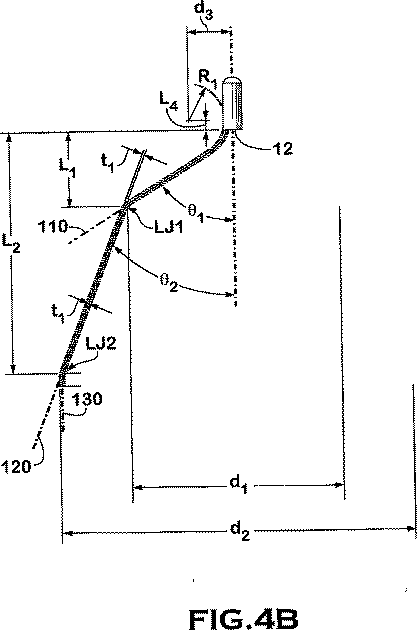
言い換えれば、各フックは、フィルタ100が28mm直径の血管において少なくとも50ミリメートルHgの圧力勾配に耐えるためおおよそ少なくとも70グラムの力に耐え得ることが必要である。
In other words, each hook needs to be able to withstand a force of approximately at least 70 grams in order for the
血管の過度の外傷を防ぐために、各個々のフックは比較的脆弱であることが必要とされる。フック数と個々のフック強度のバランスをとることにより、少なくとも50ミリメートルHgの圧力勾配基準、又は10mmHgから150mmHgの範囲内の他の何らかの所定圧力勾配基準を維持しながらも、血管の損傷を最小にすることができる。 Each individual hook is required to be relatively fragile to prevent excessive trauma of the blood vessel. Balancing the number of hooks and the individual hook strength minimizes vessel damage while maintaining a pressure gradient reference of at least 50 millimeters Hg, or some other predetermined pressure gradient reference in the range of 10 mmHg to 150 mmHg can do.
図4Aを参照すると、係止部材30は、各係止部材30の外側端部に離間して隣接する係止接合部又は曲げ部AJ1から外方に曲げることができる。係止部材30が、カテーテル又は他の管体内の圧縮から血管に解放されると、各係止部材のこの曲げ部は、フック40が実質的に管体内でバネ付勢され、フックが管体から展開されるときに交差しないことを保証する。係止部材30が肩部30から外方に曲げられているので、挿入管が引き抜かれるとフック40は迅速に外方に展開される。
Referring to FIG. 4A, the locking
別の実施形態では、例えば、フィルタの一部へのコーティング、或いはフィルタの表面上、内側、又はフィルタに付着された溶解可能構造によって血液フィルタに生体活性剤を組み込むことができる。生体活性剤は、フィルタに関連する他の症状(例えば感染又は炎症など)の治療又は予防のため、或いはフィルタ自体には関係しない他の症状の治療のためにフィルタの一部として含むことができる。更に具体的には、生体活性剤には、限定ではないが、例えば、ビンカアルカロイド(すなわち、ビンブラスチン、ビンクリスチン、及びビノレルビン)、パクリタキセル、エピジポドフィロトキシン(すなわちエトポシド、テニポシド)、抗生物質(ダクチノマイシン(アクチノマイシンD)、ダウノルビシン、ドキソルビシン、及びイダルビシン)、アントラサイクリン、ミトキサントロン、ブレオマイシン、プリカマイシン(ミトラマイシン)、及びマイトマイシン、酵素(全身的にL−アスパラギンを代謝させて自らアスパラギンを合成する能力を持たない細胞を死滅させるL−アスパラギナーゼ)などの天然物を含む抗増殖剤/抗有糸分裂薬;
G(GP)IIb/IIIa抑制剤及びビトロネクチン受容体拮抗剤などの抗血小板剤;
ナイトロジェンマスタード(メクロレタミン、シクロホスファミド及び類似体、メルファラン、クロラムブシル)、エチレンイミン及びメチルメラミン(ヘキサメチルメラミン及びチオテパ)、スルホン酸アルキル−ブスルファン、ニルトソウレア(カルムスチン(BCNU)及び類似体、ストレプトゾシン)、並びにトラゼン−ダカルバジニン(DTIC)などの抗増殖性/抗有糸分裂性アルキル化剤;
葉酸類似体(メトトレキサート)、ピリミジン類似体(フルオロウラシル、フロクスウリジン、及びシタラビン)、プリン類似体、並びに関連抑制剤(メルカプトプリン、チオグアニン、ペントスタチン、及び2−クロロデオキシアデノシン{クラドリビン})などの抗増殖性/抗有糸分裂性代謝拮抗剤;
白金配位錯体(シスプラチン、カルボプラチン)、プロカルバジン、ヒドロキシウレア、ミトタン、アミノグルテチミド;
ホルモン(すなわちエストロゲン);
抗凝血剤(ヘパリン、合成ヘパリン塩、及び他のトロンビン抑制剤);
線維素溶解剤(組織プラスミノゲン活性化因子、ストレプトキナーゼ、及びウロキナーゼなど)、アスピリン、ジピリダモール、チクロピジン、クロピドグレル、アブシキマブ;
遊走抑制剤;
分泌抑制剤(例えばブレベルジン);
副腎皮質ステロイド(コルチゾール、コルチゾン、フルドロコルチゾン、プレドニゾン、プレドニゾロン、6α−メチルプレドニゾロン、トリアムシノロン、ベータメタゾン、及びデキサメタゾン)、非ステロイド剤(サリチル酸誘導体すなわちアスピリン)などの抗炎症剤;
パラアミノフェノール誘導体、すなわちアセトミノフェン;
インドール及びインデン酢酸(インドメタシン、スリンダク、及びエトダラク)、ヘテロアリール酢酸(トルメチン、ジクロフェナク、及びケトロラク)、アリールプリピオン酸(イブプロフェン及び誘導体)、アントラニル酸(メフェナミン酸及びメクロフェナミン酸)、エノール酸(ピロキシカム、テノキシカム、フェニルブタゾン、及びオキシフェンタトラゾン)、ナブメトン、金化合物(オーラノフィン、オーロチオグルコース、金チオリンゴ酸ナトリウム);
免疫抑制剤(シクロスポリン、タクロリムス(FK−506)、シロリムス(ラパマイシン)、アザチオプリン、ミコフェノール酸モフェチル);
血管内皮細胞増殖因子(VEGF)、線維芽細胞増殖因子(FGF)などの血管形成剤;
アンギオテンシン受容体遮断薬;
一酸化窒素供与体;
アンチセンスオリジオヌクレオチド及びその組み合わせ;
mTOR阻害剤及び増殖因子受容体シグナル伝達キナーゼ阻害剤などの細胞周期阻害剤;
レテノイド;
サイクリン/CDK阻害剤;
HMG補酵素還元酵素阻害剤(スタチン);
プロテアーゼ抑制剤;
などの製薬剤を含むことができる。
In another embodiment, the bioactive agent can be incorporated into the blood filter, for example, by coating on a portion of the filter, or by a dissolvable structure attached to the surface, inside, or to the filter. The bioactive agent can be included as part of the filter for the treatment or prevention of other symptoms associated with the filter (eg, infection or inflammation) or for the treatment of other symptoms not related to the filter itself. . More specifically, bioactive agents include, but are not limited to, for example, vinca alkaloids (ie, vinblastine, vincristine, and vinorelbine), paclitaxel, epidipodophyllotoxin (ie, etoposide, teniposide), antibiotics ( Dactinomycin (actinomycin D), daunorubicin, doxorubicin, and idarubicin), anthracycline, mitoxantrone, bleomycin, primycin (mitromycin), and mitomycin, enzyme (systemically metabolizing L-asparagine and asparagine itself) Anti-proliferative / anti-mitotic agents including natural products such as L-asparaginase that kills cells that do not have the ability to synthesize;
Antiplatelet agents such as G (GP) IIb / IIIa inhibitors and vitronectin receptor antagonists;
Nitrogen mustard (mechloretamine, cyclophosphamide and analogs, melphalan, chlorambucil), ethyleneimine and methylmelamine (hexamethylmelamine and thiotepa), alkyl-busulfan sulfonate, niltsourea (carmustine (BCNU)) and analogs, strept Zocine), as well as anti-proliferative / anti-mitotic alkylating agents such as trazen-dacarbazinin (DTIC);
Such as folic acid analogues (methotrexate), pyrimidine analogues (fluorouracil, floxuridine, and cytarabine), purine analogues, and related inhibitors (mercaptopurine, thioguanine, pentostatin, and 2-chlorodeoxyadenosine {Cladribine}) Anti-proliferative / anti-mitotic antimetabolite;
Platinum coordination complexes (cisplatin, carboplatin), procarbazine, hydroxyurea, mitotane, aminoglutethimide;
Hormones (ie estrogens);
Anticoagulants (heparin, synthetic heparin salts, and other thrombin inhibitors);
Fibrinolytic agents (such as tissue plasminogen activator, streptokinase, and urokinase), aspirin, dipyridamole, ticlopidine, clopidogrel, abciximab;
Migration inhibitor;
Secretory inhibitors (eg, blavezine);
Anti-inflammatory agents such as corticosteroids (cortisol, cortisone, fludrocortisone, prednisone, prednisolone, 6α-methylprednisolone, triamcinolone, betamethasone, and dexamethasone), non-steroidal agents (salicylic acid derivatives or aspirin);
Paraaminophenol derivatives, ie acetominophen;
Indole and indene acetic acid (indomethacin, sulindac, and etodalac), heteroaryl acetic acid (tolmethine, diclofenac, and ketorolac), arylprepionic acid (ibuprofen and derivatives), anthranilic acid (mefenamic acid and meclofenamic acid), enolic acid (piroxicam, Tenoxicam, phenylbutazone, and oxyfentatrazone), nabumetone, gold compounds (auranofin, aurothioglucose, gold sodium thiomalate);
Immunosuppressants (cyclosporine, tacrolimus (FK-506), sirolimus (rapamycin), azathioprine, mycophenolate mofetil);
Angiogenic agents such as vascular endothelial growth factor (VEGF), fibroblast growth factor (FGF);
Angiotensin receptor blockers;
Nitric oxide donors;
Antisense oligonucleotides and combinations thereof;
cell cycle inhibitors such as mTOR inhibitors and growth factor receptor signaling kinase inhibitors;
Retenoids;
Cyclin / CDK inhibitor;
HMG coenzyme reductase inhibitor (statin);
Protease inhibitors;
And the like.
例えば、引用により本明細書に組み込まれる米国特許第6,258,026号に記載されたユニットのような、フィルタ供給ユニット(図示せず)は、上記特許で詳細に説明されているようにフィルタ100をカテーテル又は供給管体から脈管内のほぼ中央部分に送達するよう適合されている。好ましくは、この供給装置は、2005年8月9日に出願された名称「Embolus Blood Clot Filter and Delivery System(塞栓血餅フィルタ及びデリバリシステム)」の米国仮特許出願番号60/706,596に示され説明された供給装置、又は先の仮特許出願に対する優先権を主張するPCT特許出願に示され記載された供給装置とすることができ、該PCT特許出願は、2006年5月9日に出願された代理人整理番号14673−003WO及びPTC出願番号____の名称「Embolus Blood Clot Filter and Delivery System(塞栓血餅フィルタ及びデリバリシステム)」であり、これら両方の出願は引用により全体が本明細書に組み込まれる。 For example, a filter supply unit (not shown), such as the unit described in US Pat. No. 6,258,026, incorporated herein by reference, is a filter as described in detail in that patent. It is adapted to deliver 100 from the catheter or supply tube to a generally central portion within the vessel. Preferably, this delivery device is shown in US Provisional Patent Application No. 60 / 706,596, filed Aug. 9, 2005, under the name “Embolus Blood Clot Filter and Delivery System”. Or a supply device as shown and described in a PCT patent application claiming priority over an earlier provisional patent application, which was filed on May 9, 2006. And the name “Embolus Blood Clot Filter and Delivery System” (embolization clot filter and delivery system), with the assigned agent docket number 14673-003WO and PTC application number ____ Built-in It is.
一実施形態では、フィルタの一部、好ましくはフィルタのハブ10に放射線不透過性材料を組み込むことができる。ここで使用する放射線不透過性材料とは、材料が哺乳動物体内にある間、機械又はヒトが可読の放射線機器に識別可能なあらゆる材料であり、例えば、限定ではなく例証として、金、タングステン、白金、バリウム、硫酸バリウム、又はタンタルなどである。フィルタ内に放射線不透過性材料を使用することにより、臨床医は、放射線透過装置を使用して被検体の血管内にフィルタを配置することが可能となる。放射線不透過性材料は、キャップ、スリーブ、シム、ワイヤ、又はハブ組立部品の回りもしくは内部へのろう付など、ハブに付加される追加構造の形態とすることができる。或いは、ハブ自体を放射線不透過性合金で形成することができる。
In one embodiment, a radiopaque material may be incorporated into a portion of the filter, preferably the
上述の実施形態のようなハブ10の代わりに、図10に示す実施形態のように、フィルタ装置200の一部として回収フックを設けることができる。フィルタ装置200は、回収フック220を有するハブ210を含む。フック220は、被検体からフィルタ200を回収するためにスネア装置が使用するように構成されている。図11及び12を参照すると、回収フック220は、ハブ210との一体部材230として、又は、例えばEDM、レーザ溶接、プラズマ溶接、溶接ろう付け、溶接、はんだ付け、接着などの好適な技術によりハブ210に接合される独立部材として形成することができる。好ましい実施形態では、部材230は、ハブ210の一部分からブラインドボア240を形成した機械加工のビレット部材とすることができる。フック部分220は、傾斜面250及び260を含み、これらは、フィルタ200のオフセットした挿入位置によりカテーテル開口部で曲がることなくフィルタ200を回収できる点で好都合であると考えられる。言い換えれば、取り出し処置中に、部材230の軸300がカテーテル回収装置の長手方向軸とほぼ平行ではない又は整列していない状況がある可能性がある。このような場合、保持力が大きくなると、フックがカテーテルの入口開口部に干渉し、これによりフィルタの回収処置が困難になる可能性が高くなると考えられている。傾斜部250及び260により、曲がり又は干渉がかなり減少すると考えられる。詳細には、図13及び14に示すように、傾斜部250は、平坦部252及び254に結合された曲率半径R4を含む。平坦部分254は、丸みの付いた面R6を有するフック部分256に結合することができる。図13に示すように、平坦部分252は、別の丸みをつけた部分R7に結合される。本明細書に提供された図面は、各図に示されたあらゆる要素に対して一定の縮尺にされている点に留意されたい。
Instead of the
ロケータ部材20及び係止部材30の一部をブラインド孔240内に保持することができる回収フック230を提供するために、前述の寸法パラメータにある範囲の値を使用することができる。例えば、より小さいフィルタは、回収フック230が静脈内で過度閉塞を生じないように、大人の大静脈又は他の血管などの大きな静脈又は血管内に配置されることを目的とされるフィルタより小さい寸法を有することができる。更に、回収フック230は、フックを回収機構と係合させる助けとなるなど、臨床医が放射線透過装置を用いながら被検体内のフックの位置を特定することができるように、放射線不透過性材料から製造され又はこれを含むことができる。
To provide a
本発明を特定の好ましい実施形態、数々の修正、変形形態を参照しながら開示したが、添付の請求項で定義されるように、本発明の領域及び範囲から逸脱することなく、説明された実施形態に対して変更することができる。従って、本発明は、説明された実施形態に限定されず、添付の請求項の表現及びその均等物により定義される全範囲を有するものとする。 Although the invention has been disclosed with reference to certain preferred embodiments, numerous modifications, and variations, the described embodiments have been described without departing from the scope and scope of the invention as defined in the appended claims. Changes can be made to the form. Accordingly, the invention is not limited to the described embodiments but is to be accorded the full scope defined by the appended claims and equivalents thereof.
10 ハブ
20 ロケータ部材
30 係止部材
40 フック
100 フィルタ
10
Claims (43)
長手方向軸に沿って配置されるハブと、
前記ハブから突出する少なくとも1つの係止部材であって、前記フィルタが前記血管内に置かれるときに血管壁を穿通するフックを含み、前記フックは前記ハブから前記長手方向軸に沿って離間され、且つ前記長手方向軸から第1の半径方向の距離を離間された少なくとも1つの係止部材と、
前記ハブから突出する少なくとも1つのロケータであって、前記ハブから前記長手方向軸に沿って離間され且つ前記長手方向軸から前記第1の半径方向距離よりも小さい第2の半径方向距離を離間された先端部分を有し、各々がそれぞれの異なる軸上に配置されている少なくとも4つの部分を有するロケータと、を備え、
前記ロケータは、前記ハブに隣接して長手方向軸に対して第1の角度を定める湾曲部分と、第1の角度で延びる第1のセグメントと、長手方向軸に対して第2の角度で延びる第2のセグメントを有し、第1の角度は略58°であり、第2の角度は略22°である、フィルタ。A filter placed in the bloodstream through a blood vessel,
A hub disposed along the longitudinal axis;
At least one locking member protruding from the hub, the hook penetrating a blood vessel wall when the filter is placed in the blood vessel, the hook being spaced apart from the hub along the longitudinal axis And at least one locking member spaced a first radial distance from the longitudinal axis;
At least one locator projecting from the hub, spaced from the hub along the longitudinal axis and spaced from the longitudinal axis by a second radial distance that is less than the first radial distance. A locator having at least four portions, each having a tip portion that is disposed on a respective different axis ,
The locator is adjacent to the hub and defines a curved portion defining a first angle with respect to the longitudinal axis, a first segment extending at the first angle, and a second angle with respect to the longitudinal axis. A filter having a second segment, the first angle is approximately 58 °, and the second angle is approximately 22 ° .
長手方向軸に沿って配置されるハブと、
前記ハブから突出する少なくとも1つの係止部材であって、前記フィルタが前記血管内に置かれるときに血管壁を穿通するフックを含み、前記フックは前記ハブから前記長手方向軸に沿って離間され、且つ前記長手方向軸から第1の半径方向の距離を離間された少なくとも1つの係止部材と、
前記ハブから突出する少なくとも1つのロケータであって、前記ハブから前記長手方向軸に沿って離間され且つ前記長手方向軸から前記第1の半径方向距離よりも小さい第2の半径方向距離を離間された先端部分を有し、前記ハブに対して遠位の第2のセグメントと前記ハブに対して近位の第1のセグメントとを有し、前記第1及び第2のセグメントの各々が、ほぼ直線であって前記長手方向軸に対して傾斜した異なる軸上に配置されており、前記第2のセグメントの長さが前記第1のセグメントの長さよりも長いロケータと、を備え、
前記第1のセグメントは長手方向軸に対して第1の角度で延び、前記第2のセグメントは第2の角度で延び、第1の角度は略58°であり、第2の角度は略22°である、フィルタ。A filter placed in the bloodstream through a blood vessel,
A hub disposed along the longitudinal axis;
At least one locking member protruding from the hub, the hook penetrating a blood vessel wall when the filter is placed in the blood vessel, the hook being spaced apart from the hub along the longitudinal axis And at least one locking member spaced a first radial distance from the longitudinal axis;
At least one locator projecting from the hub, spaced from the hub along the longitudinal axis and spaced from the longitudinal axis by a second radial distance that is less than the first radial distance. A second segment distal to the hub and a first segment proximal to the hub, each of the first and second segments being approximately A locator that is straight and disposed on a different axis that is inclined with respect to the longitudinal axis, wherein the length of the second segment is longer than the length of the first segment ;
The first segment extends at a first angle relative to the longitudinal axis, the second segment extends at a second angle, the first angle is approximately 58 °, and the second angle is approximately 22 The filter that is ° .
長手方向軸に沿って配置されるハブと、
前記ハブから分岐する複数の係止部材であって、各係止部材が、前記血管内に配置されるときに、(i)前記血管の壁を穿通する、(ii)前記長手方向軸に沿って前記ハブから離間されている、及び(iii)前記長手方向軸から第1の半径方向距離を離間されたフックを含む係止部材と、
前記ハブから分岐する複数のロケータであって、各ロケータが、
前記ハブに隣接するベース部分と、
前記ベース部分から第1の軸に沿って延びる第1のセグメントと、
前記第1のセグメントから前記第1の軸とは異なる第2の軸に沿って延びる第2のセグメントと、
前記第2のセグメントから前記第1及び第2の軸とは異なる先端軸に沿って延びる先端部分であって、(i)前記フィルタが前記血管内に置かれるときに前記血管壁と係合し、(ii)前記ハブから前記長手方向軸に沿って離間し、(iii)前記長手方向軸から前記第1の半径方向距離よりも小さい第2の半径方向距離を離間した先端部分と、
を含むロケータと、を備え、
前記第1のセグメントは長手方向軸に対して第1の角度で延び、前記第2のセグメントは第2の角度で延び、第1の角度は略58°であり、第2の角度は略22°であるフィルタ。A filter placed in a blood vessel,
A hub disposed along the longitudinal axis;
A plurality of locking members bifurcated from the hub, wherein each locking member , when placed in the blood vessel, (i) penetrates the wall of the blood vessel; (ii) along the longitudinal axis A locking member including a hook spaced from the hub, and (iii) a first radial distance from the longitudinal axis;
A plurality of locators branched from the hub, each locator,
A base portion adjacent to the hub;
A first segment extending from the base portion along a first axis;
A second segment extending along different second axis from said first axis from said first segment,
A tip portion extending from the second segment along a tip axis different from the first and second axes, and (i) engages the vessel wall when the filter is placed in the vessel. (Ii) a tip portion spaced from the hub along the longitudinal axis, and (iii) a distal portion spaced from the longitudinal axis by a second radial distance that is less than the first radial distance ;
And a locator, including,
The first segment extends at a first angle relative to the longitudinal axis, the second segment extends at a second angle, the first angle is approximately 58 °, and the second angle is approximately 22 ° der Ru filter.
長手方向軸に沿って配置されるハブと、
前記ハブから分岐する複数の係止部材であって、各係止部材が、(i)前記フィルタが前記血管内に置かれるときに前記血管の壁を穿通し、(ii)前記ハブから前記長手方向軸に沿って離間され、及び(iii)前記長手方向軸から第1の半径方向距離を離間されたフックを含む係止部材と、
前記ハブから分岐する複数のロケータと、
を備え、
前記各ロケータが、
前記ハブに隣接するベース部分と、
(i)前記血管の壁に係合し、(ii)前記ハブから前記長手方向軸に沿って離間し、及び(iii)前記長手方向軸から前記第1の半径方向距離よりも小さい第2の半径方向距離を離間した先端部分と、
前記ベース部分と前記先端部分とを結合する中間部分であって、前記長手方向軸に対して第1の角度で傾斜している第1の軸に沿って前記ベース部分から第1の長さを延びる直線の第1のセグメントと、前記先端部分と第1のセグメントとの間に前記第1の長さよりも大きい第2の長さを前記長手方向軸に対して第2の角度で傾斜し且つ前記第1の軸とは異なる第2の軸に沿って延びた直線の第2のセグメントとを含む中間部分と、
を含み、第1の角度は略58°であり、第2の角度は略22°である、ことを特徴とするフィルタ。A filter placed in a blood vessel,
A hub disposed along the longitudinal axis;
A plurality of locking members bifurcated from the hub, wherein each locking member (i) penetrates the wall of the blood vessel when the filter is placed in the blood vessel; (ii) the longitudinal from the hub A locking member including a hook spaced along a directional axis, and (iii) a first radial distance from the longitudinal axis;
A plurality of locators branched from the hub;
With
Each locator is
A base portion adjacent to the hub;
(Ii) engaging the vessel wall; (ii) spaced apart from the hub along the longitudinal axis; and (iii) a second less than the first radial distance from the longitudinal axis. A tip portion separated by a radial distance ;
A first portion from the base portion along a first axis that is an intermediate portion joining the base portion and the tip portion and is inclined at a first angle with respect to the longitudinal axis. A first straight segment extending and a second length greater than the first length between the tip portion and the first segment inclined at a second angle with respect to the longitudinal axis; An intermediate portion including a straight second segment extending along a second axis different from the first axis;
Only containing the first angle is approximately 58 °, the second angle is approximately 22 °, filter, characterized in that.
前記1つの方向で前記長手方向軸に沿って前記本体から離れて傾斜して延び、前記本体に隣接する前記複数の係止部材に結合された複数のロケータ部材と、
を備え、
前記複数のロケータ部材の各々が第1、第2、及び第3のセグメントを有し、前記第1のセグメントは前記長手方向軸から湾曲経路に沿って延びて前記長手方向軸に対して第1の角度を定める湾曲部分により前記本体に接続され、前記第2のセグメントは前記長手方向軸に対して第2の角度で延びており、前記第3のセグメントは前記長手方向軸にほぼ平行に延びており、
第1の角度は略58°であり、第2の角度は略22°である、ことを特徴とする血液フィルタ。A plurality of locking members coupled together to define a body extending along the longitudinal axis, each extending obliquely away from the body in one direction;
A plurality of locator members extending obliquely away from the body along the longitudinal axis in the one direction and coupled to the plurality of locking members adjacent to the body;
With
Each of the plurality of locator members has first, second, and third segments, the first segment extending from the longitudinal axis along a curved path and first with respect to the longitudinal axis. are connected by a curved portion defining an angle of said main body, said second segment extends at a second angle relative to the longitudinal axis, the third segment extending substantially parallel to said longitudinal axis and,
The blood filter, wherein the first angle is about 58 ° and the second angle is about 22 ° .
ことを特徴とする請求項5に記載の血液フィルタ。The body further includes a tubular member surrounding the plurality of locator members and defining a hub;
The blood filter according to claim 5 .
ことを特徴とする請求項5に記載の血液フィルタ。A third segment of each locator extends at a third angle with respect to the longitudinal axis;
The blood filter according to claim 5 .
ことを特徴とする請求項7に記載の血液フィルタ。The first angle is greater than the third angle;
The blood filter according to claim 7 .
ことを特徴とする請求項8に記載の血液フィルタ。The third angle is less than about 1 degree;
The blood filter according to claim 8 .
ことを特徴とする請求項1〜4のいずれか一項に記載の血液フィルタ。The hook is offset in a straight line with respect to an axis on which at least one segment of the locking member is aligned;
The blood filter according to any one of claims 1 to 4, wherein:
第4の角度で前記長手方向軸から離れて延びる第1の係止セグメントと、
第5の角度で前記長手方向軸から離れて延びる第2の係止セグメントと、
保持部分と、
を備えることを特徴とする請求項9に記載の血液フィルタ。Each of the plurality of locking members is
A first locking segment extending away from the longitudinal axis at a fourth angle;
A second locking segment extending away from the longitudinal axis at a fifth angle;
Holding part;
The blood filter according to claim 9 , comprising:
ことを特徴とする請求項11に記載の血液フィルタ。At least two of the plurality of locator members define a first virtual circle having a first diameter extending through the longitudinal axis;
The blood filter according to claim 11 .
ことを特徴とする請求項12に記載の血液フィルタ。The locator includes a hook that engages the wall of the blood vessel;
The blood filter according to claim 12 .
ことを特徴とする請求項12に記載の血液フィルタ。At least two of the plurality of locking members define a second imaginary circle having a second diameter extending through the longitudinal axis, wherein the second diameter is about 1. Double
The blood filter according to claim 12 .
ことを特徴とする請求項14に記載の血液フィルタ。The end portion includes a length along a longitudinal axis of about 0.05 inches;
The blood filter according to claim 14 .
ことを特徴とする請求項15に記載の血液フィルタ。The curved portion includes a radius of curvature of about 0.1 inches about an axis substantially perpendicular to the longitudinal axis;
The blood filter according to claim 15 .
ことを特徴とする請求項16に記載の血管フィルタ。The retaining portion includes a hook;
The blood vessel filter according to claim 16 .
ことを特徴とする請求項17に記載の血液フィルタ。The hook includes a curved shape in the activated state and a substantially linear shape in the restrained state.
The blood filter according to claim 17 .
ことを特徴とする請求項18に記載の血液フィルタ。The hook includes a curved shape in an activated state, and the locking member is twisted about an axis in the restrained state of the filter;
The blood filter according to claim 18 .
ことを特徴とする請求項19に記載の血液フィルタ。The hook is in the restrained state when a force of at least about 70 grams or more is applied to each locator along the longitudinal axis.
The blood filter according to claim 19 .
ことを特徴とする請求項20に記載の血液フィルタ。The locking member includes a cross-sectional area of about 0.00013 square inches;
The blood filter according to claim 20 .
ことを特徴とする請求項21に記載の血液フィルタ。The hook includes a curved member having a cross-sectional area of about 0.000086 square inches;
The blood filter according to claim 21 .
ことを特徴とする請求項1〜4の何れか一項に記載のフィルタ。Defining a first circle the hook has a radius equal to said first radial distance, defining a second circle which the tip portion has a radius equal to the second radial distance, said first and second Two circles are substantially concentric about the longitudinal axis;
The filter as described in any one of Claims 1-4 characterized by the above-mentioned.
を備える、
ことを特徴とする請求項1〜4、13、17〜23のいずれか1項に記載のフィルタ。Each of the locking members includes a first locking segment extending substantially parallel to the longitudinal axis; a second locking segment extending tangentially to the respective hook; an intermediate locking segment extending, coupled diagonally to each of the first and second locking segments of the respective between the second locking segment,
Comprising
The filter according to any one of claims 1 to 4 , 13 , and 17 to 23 .
ことを特徴とする請求項24に記載のフィルタ。Each first, second, and intermediate locking segment extends generally linearly;
The filter according to claim 24 .
ことを特徴とする請求項25に記載のフィルタ。Each first, second, and intermediate locking segment extends in a curvilinear manner;
26. The filter according to claim 25 .
ことを特徴とする請求項26に記載のフィルタ。Each of the second locking segments extends at an angle with respect to the major axis at a first angle, and each of the intermediate locking segments has a second angle that is less than the first angle. Extending obliquely with respect to the long axis,
27. A filter according to claim 26 .
前記先端部分が約0.05インチの長手方向軸に沿った長さを有し、
前記湾曲部分が約0.1インチの曲率半径を含み、
前記ロケータの第1の部分が、前記長手方向軸から約0.4インチ及び前記長手方向軸に沿って測定して前記ハブから約0.3インチ延びており、
前記ロケータの第2の部分が、前記長手方向軸から約0.75インチ及び前記長手方向軸に沿って測定して前記ハブから約0.9インチ延びており、
前記係止部材の前記フックの部分が前記長手方向軸から約0.75及び前記長手方向軸に沿って測定して前記ハブから約1.3インチに位置し、
前記フックが約0.03インチの曲率半径を含む、
ことを特徴とする請求項1に記載のフィルタ。When the filter is in an unsuppressed state,
The tip portion has a length along a longitudinal axis of about 0.05 inches;
The curved portion includes a radius of curvature of about 0.1 inches;
A first portion of the locator extends about 0.4 inches from the longitudinal axis and about 0.3 inches from the hub as measured along the longitudinal axis;
A second portion of the locator extends about 0.75 inches from the longitudinal axis and about 0.9 inches from the hub as measured along the longitudinal axis;
The portion of the hook of the locking member is located about 0.75 from the longitudinal axis and about 1.3 inches from the hub as measured along the longitudinal axis;
The hook includes a radius of curvature of about 0.03 inches;
The filter according to claim 1 .
ことを特徴とする請求項24に記載のフィルタ。The intermediate locking segment defines a cone having a first apex disposed along the longitudinal axis adjacent to the hub;
The filter according to claim 24 .
第1の端部から第2の端部まで長手方向軸に沿って延びる本体と、
フィルタの非抑制形状において、前記第1及び第2の端部から離れて前記本体の前記第2の端部から傾斜して延びる複数の係止部材と、
を備え、
前記複数の係止部材が、前記長手方向軸に沿った長さを有し、いずれかの2つの係止部材の間の最大幅を前記長さの少なくとも0.9倍に定めて、前記フィルタが前記血管内に置かれたときに各係止部材に接続されたフックが前記血管の壁を穿通するようにされており、
前記血液フィルタには更に、
前記本体の前記第1及び第2の端部から離れて前記本体の第2の端部から傾斜して延びて、各々の一部分が前記壁に係合するようされた複数のロケータが設けられており、
前記ロケータは、長手方向軸に対して第1の角度で延びる第1のセグメントと、第2の角度で延びる第2のセグメントを有し、第1の角度は略58°であり、第2の角度は略22°である、
ことを特徴とする血液フィルタ。A blood filter for attachment to a blood vessel,
A body extending along the longitudinal axis from the first end to the second end;
In the non-inhibiting shape of the filter, a plurality of locking members extending from the first end of the main body and inclined from the first and second ends,
With
The plurality of locking members have a length along the longitudinal axis, and a maximum width between any two locking members is set to at least 0.9 times the length; A hook connected to each locking member penetrates the wall of the blood vessel when it is placed in the blood vessel,
The blood filter further includes
A plurality of locators are provided that extend away from the first and second ends of the body and incline from the second end of the body, each portion engaging the wall. And
The locator has a first segment extending at a first angle with respect to the longitudinal axis and a second segment extending at a second angle, the first angle being approximately 58 °, The angle is approximately 22 °.
A blood filter characterized by that.
ことを特徴とする請求項30に記載の血液フィルタ。At least one of the locators includes a hook disposed adjacent to the portion;
The blood filter according to claim 30 , wherein
ことを特徴とする請求項31に記載の血液フィルタ。At least one of the locators includes a stop member disposed adjacent to the portion;
32. The blood filter according to claim 31 , wherein:
第1の端部から第2の端部まで第1の方向で長手方向軸に沿って延びるハブと、
各々が3つのほぼ直線状のセグメントを有する複数のロケータであって、該3つのほぼ直線状のセグメントがいずれかの2つのセグメント間の接合部で弓状のセグメントと共に接続され、前記セグメントはロケータを形成するように構成され、前記ほぼ直線状のセグメントの各々が、前記第1の方向に延びる異なる軸上に配置されている、複数のロケータと、
異なる軸上に配置された2つのほぼ直線状のセグメントと、前記ハブに結合された弓状のセグメントとにフックを接続した複数の係止部材と、を備え、
前記ロケータは、長手方向軸に対して第1の角度で延びる第1のセグメントと、第2の角度で延びる第2のセグメントを有し、第1の角度は略58°であり、第2の角度は略22°であることを特徴とする血液フィルタ。A blood filter placed in a blood vessel,
A hub extending along a longitudinal axis in a first direction from a first end to a second end;
A plurality of locators each having three generally linear segments, the three generally linear segments being connected together with an arcuate segment at the junction between any two segments, said segments being locators A plurality of locators, each of the substantially linear segments being disposed on different axes extending in the first direction;
A plurality of locking members having hooks connected to two generally linear segments disposed on different axes and an arcuate segment coupled to the hub ;
The locator has a first segment extending at a first angle with respect to the longitudinal axis and a second segment extending at a second angle, the first angle being approximately 58 °, blood filter angle, wherein substantially 22 ° der Rukoto.
ことを特徴とする請求項33に記載のフィルタ。The generally straight segment includes a curved segment;
34. The filter according to claim 33 .
請求項1から34のいずれか1項に記載のフィルタ。Further comprising a bioactive agent;
The filter according to any one of claims 1 to 34 .
ことを特徴とする請求項1〜4、6〜29、33および34のいずれか1項に記載のフィルタ。Further comprising a bioactive agent coupled to the filter and a radiopaque material disposed adjacent to the hub.
The filter according to any one of claims 1 to 4, 6 to 29 , 33, and 34 .
各々が末端部分を有する複数のロケータを長手方向軸の周りに配置する段階と、
前記長手方向軸のまわりに仮想円柱を定めるように前記末端部分を構成する段階と、
前記複数のロケータに対して、保持部分に結合された主要部分を各々が有する複数の係止部材を接続する段階と、
前記長手方向軸の周りに仮想円錐を定めるように前記係止部材の主要部分を配向する段階と、を含み、
前記ロケータは、長手方向軸に対して第1の角度で延びる第1のセグメントと、第2の角度で延びる第2のセグメントを有し、第1の角度は略58°であり、第2の角度は略22°である方法。A method of manufacturing a blood filter, comprising:
Placing a plurality of locators, each having a distal portion, about a longitudinal axis;
Configuring the end portion to define a virtual cylinder about the longitudinal axis;
Connecting a plurality of locking members each having a main portion coupled to a holding portion to the plurality of locators;
Orienting the main portion of the locking member to define a virtual cone about the longitudinal axis ;
The locator has a first segment extending at a first angle with respect to the longitudinal axis and a second segment extending at a second angle, the first angle being approximately 58 °, A method in which the angle is approximately 22 ° .
前記第1のセグメントがフックに接続されて第1の長さを有し、前記第2のセグメントが前記第1のセグメントの長さの約450パーセントの長さを有し、前記第3のセグメントが前記第1のセグメントの長さの約27パーセントの長さを有する、
ことを特徴とする請求項39に記載の方法。The orientation step includes forming wires in the first, second, and third segments;
The first segment is connected to a hook and has a first length; the second segment has a length of about 450 percent of the length of the first segment; and the third segment Has a length of about 27 percent of the length of the first segment;
40. The method of claim 39 .
ことを特徴とする請求項40に記載の方法。The virtual cone includes a substantially circular bottom surface having a diameter of about 1.1 times the diameter of the virtual cylinder;
41. The method of claim 40 .
ことを特徴とする請求項37に記載の方法。At least one of the end portions of the locator includes at least one of a hook and a stop member;
38. The method of claim 37 .
Applications Claiming Priority (3)
| Application Number | Priority Date | Filing Date | Title |
|---|---|---|---|
| US68060105P | 2005-05-12 | 2005-05-12 | |
| US60/680,601 | 2005-05-12 | ||
| PCT/US2006/017889 WO2006124405A2 (en) | 2005-05-12 | 2006-05-09 | Removable embolus blood clot filter |
Publications (2)
| Publication Number | Publication Date |
|---|---|
| JP2008544771A JP2008544771A (en) | 2008-12-11 |
| JP5102201B2 true JP5102201B2 (en) | 2012-12-19 |
Family
ID=37431823
Family Applications (1)
| Application Number | Title | Priority Date | Filing Date |
|---|---|---|---|
| JP2008511266A Active JP5102201B2 (en) | 2005-05-12 | 2006-05-09 | Removable embolic clot filter |
Country Status (6)
| Country | Link |
|---|---|
| US (6) | US7967838B2 (en) |
| EP (1) | EP1880313B1 (en) |
| JP (1) | JP5102201B2 (en) |
| CA (3) | CA2946470C (en) |
| MX (1) | MX2007013932A (en) |
| WO (1) | WO2006124405A2 (en) |
Cited By (8)
| Publication number | Priority date | Publication date | Assignee | Title |
|---|---|---|---|---|
| US8430903B2 (en) | 2005-08-09 | 2013-04-30 | C. R. Bard, Inc. | Embolus blood clot filter and delivery system |
| US8613754B2 (en) | 2005-05-12 | 2013-12-24 | C. R. Bard, Inc. | Tubular filter |
| US8628556B2 (en) | 2004-08-04 | 2014-01-14 | C. R. Bard, Inc. | Non-entangling vena cava filter |
| US9131999B2 (en) | 2005-11-18 | 2015-09-15 | C.R. Bard Inc. | Vena cava filter with filament |
| US9351821B2 (en) | 1998-09-25 | 2016-05-31 | C. R. Bard, Inc. | Removable embolus blood clot filter and filter delivery unit |
| US9498318B2 (en) | 2005-05-12 | 2016-11-22 | C.R. Bard, Inc. | Removable embolus blood clot filter |
| US10188496B2 (en) | 2006-05-02 | 2019-01-29 | C. R. Bard, Inc. | Vena cava filter formed from a sheet |
| US12115057B2 (en) | 2005-05-12 | 2024-10-15 | C.R. Bard, Inc. | Tubular filter |
Families Citing this family (40)
| Publication number | Priority date | Publication date | Assignee | Title |
|---|---|---|---|---|
| US9204956B2 (en) | 2002-02-20 | 2015-12-08 | C. R. Bard, Inc. | IVC filter with translating hooks |
| US20060271067A1 (en) * | 2005-05-24 | 2006-11-30 | C.R. Bard, Inc. | Laser-resistant surgical devices |
| EP1965729A2 (en) | 2005-12-30 | 2008-09-10 | C.R. Bard, Inc. | Removable blood clot filter with edge for cutting through the endothelium |
| WO2007079407A2 (en) | 2005-12-30 | 2007-07-12 | C.R. Bard Inc. | Embolus blood clot filter with post delivery actuation |
| CA2633855A1 (en) | 2005-12-30 | 2007-07-12 | C.R. Bard Inc. | Embolus blood clot filter delivery system |
| EP1965728A2 (en) | 2005-12-30 | 2008-09-10 | C.R. Bard, Inc. | Embolus blood clot filter with floating filter basket |
| WO2007079415A2 (en) | 2005-12-30 | 2007-07-12 | C.R. Bard Inc. | Embolus blood clot filter removal system and method |
| WO2007143602A2 (en) | 2006-06-05 | 2007-12-13 | C.R. Bard Inc. | Embolus blood clot filter utilizable with a single delivery system or a single retrieval system in one of a femoral or jugular access |
| US20080300620A1 (en) * | 2007-05-31 | 2008-12-04 | C.R. Bard, Inc. | Embolic filter made from a composite material |
| US8795318B2 (en) * | 2007-09-07 | 2014-08-05 | Merit Medical Systems, Inc. | Percutaneous retrievable vascular filter |
| US8062328B2 (en) | 2007-09-07 | 2011-11-22 | Merit Medical Systems, Inc. | Percutaneous permanent retrievable vascular filter |
| US9044305B2 (en) * | 2008-04-03 | 2015-06-02 | Cook Medical Technologies Llc | Self cleaning devices, systems and methods of use |
| EP2429624B1 (en) | 2009-05-15 | 2014-04-02 | Intersect ENT, Inc. | A combination of an expandable device and a delivery device. |
| US20110106136A1 (en) * | 2009-10-29 | 2011-05-05 | Medtronic Vascular, Inc. | IVC Filter With Drug Delivery |
| FR2952295B1 (en) * | 2009-11-06 | 2012-01-06 | A L N | FILTER FOR CELLULAR VEIN AND KITS CONTAINING THE SAME |
| US20120277774A1 (en) * | 2009-11-13 | 2012-11-01 | The Brigham And Women's Hospital, Inc. | Method and Apparatus for Vascular Anastomosis |
| EP2523629B1 (en) | 2010-01-12 | 2021-04-14 | Cook Medical Technologies LLC | Visual stabilizer on anchor legs of vena cava filter |
| US8469970B2 (en) * | 2011-07-11 | 2013-06-25 | Great Aspirations Ltd. | Apparatus for entrapping and extracting objects from body cavities |
| US9039715B2 (en) | 2011-07-11 | 2015-05-26 | Great Aspirations Ltd. | Apparatus for entrapping and extracting objects from body cavities |
| US8734480B2 (en) | 2011-08-05 | 2014-05-27 | Merit Medical Systems, Inc. | Vascular filter |
| US8740931B2 (en) | 2011-08-05 | 2014-06-03 | Merit Medical Systems, Inc. | Vascular filter |
| CA2864352A1 (en) * | 2012-01-13 | 2013-07-18 | Volcano Corporation | Endoluminal filter with fixation |
| US9452039B2 (en) | 2012-02-23 | 2016-09-27 | Merit Medical Systems, Inc. | Vascular filter |
| DE102012010687B4 (en) | 2012-05-30 | 2021-08-19 | ADMEDES GmbH | A method for producing a body implant, an assembly comprising a guide wire and a body implant, and a medical instrument |
| US9101449B2 (en) | 2012-07-27 | 2015-08-11 | Cook Medical Technologies Llc | Filter removal device |
| US9358021B2 (en) | 2013-01-09 | 2016-06-07 | Covidien Lp | Connection of an endovascular intervention device to a manipulation member |
| CN105188599B (en) * | 2013-02-08 | 2017-12-26 | 玛芬股份有限公司 | Peripherally Sealing Venous Check Valve |
| CN105188831B (en) | 2013-03-14 | 2021-01-01 | 因特尔赛克特耳鼻喉公司 | Systems, devices, and methods for treating sinus conditions |
| EP3030194B1 (en) | 2013-08-09 | 2019-03-13 | Merit Medical Systems, Inc. | Vascular filter delivery systems |
| US10010398B2 (en) | 2013-10-01 | 2018-07-03 | Cook Medical Technologies Llc | Filter device, system, and method |
| GB2527761A (en) * | 2014-06-30 | 2016-01-06 | Cook Medical Technologies Llc | Improved vascular filter and anchoring arrangement therefor |
| US10117736B2 (en) | 2014-08-06 | 2018-11-06 | Cook Medical Technologies Llc | Low radial force filter |
| CN107397588B (en) * | 2016-05-20 | 2020-03-06 | 中国科学院深圳先进技术研究院 | Simulation method and device for interventional embolization procedure |
| CN207821947U (en) * | 2017-04-11 | 2018-09-07 | 杭州唯强医疗科技有限公司 | With from central vena cava filter |
| KR101965637B1 (en) | 2017-07-31 | 2019-04-03 | (주) 타우피엔유메디칼 | A device for the treatment of tricuspid regurgitation in the pulmonary artery |
| KR101972991B1 (en) | 2017-07-31 | 2019-08-16 | (주) 타우피엔유메디칼 | Equipment for the treatment of tricuspid regurgitation |
| KR102156647B1 (en) | 2019-01-21 | 2020-09-16 | (주) 타우피엔유메디칼 | An assembled device for treatment of tricuspid regurgitation |
| WO2021047604A1 (en) * | 2019-09-12 | 2021-03-18 | 深圳市科奕顿生物医疗科技有限公司 | Intracavitary implant structure and vena cava filter having said structure |
| US11446114B2 (en) * | 2020-01-21 | 2022-09-20 | Med-Genesis, Llc | Biopsy marker with anchoring capabilities |
| US11738188B2 (en) | 2020-06-08 | 2023-08-29 | Covidien Lp | Connection of intravascular interventional elements and elongate manipulation members |
Family Cites Families (517)
| Publication number | Priority date | Publication date | Assignee | Title |
|---|---|---|---|---|
| US893055A (en) | 1908-01-23 | 1908-07-14 | William W Conner | Cork-extractor. |
| US2212334A (en) | 1936-08-15 | 1940-08-20 | Mueller & Co V | Catheter |
| US2767703A (en) | 1955-01-07 | 1956-10-23 | Herbert E Nieburgs | Exploratory device for cell specimens |
| US3334629A (en) | 1964-11-09 | 1967-08-08 | Bertram D Cohn | Occlusive device for inferior vena cava |
| US3472230A (en) | 1966-12-19 | 1969-10-14 | Fogarty T J | Umbrella catheter |
| US3540431A (en) | 1968-04-04 | 1970-11-17 | Kazi Mobin Uddin | Collapsible filter for fluid flowing in closed passageway |
| US3579798A (en) * | 1969-02-13 | 1971-05-25 | William P Henderson | Method of verifying the replacement of a damaged windshield |
| US3657744A (en) | 1970-05-08 | 1972-04-25 | Univ Minnesota | Method for fixing prosthetic implants in a living body |
| US3620212A (en) | 1970-06-15 | 1971-11-16 | Robert D Fannon Jr | Intrauterine contraceptive device |
| JPS512201B1 (en) | 1971-05-29 | 1976-01-23 | ||
| US3875928A (en) | 1973-08-16 | 1975-04-08 | Angelchik Jean P | Method for maintaining the reduction of a sliding esophageal hiatal hernia |
| US3885562A (en) | 1973-11-16 | 1975-05-27 | John C Lampkin | Syringe with writing surface |
| US3952747A (en) | 1974-03-28 | 1976-04-27 | Kimmell Jr Garman O | Filter and filter insertion instrument |
| US4000739A (en) | 1975-07-09 | 1977-01-04 | Cordis Corporation | Hemostasis cannula |
| US4041931A (en) | 1976-05-17 | 1977-08-16 | Elliott Donald P | Radiopaque anastomosis marker |
| JPS5394515A (en) | 1977-01-31 | 1978-08-18 | Kubota Ltd | Method of producing glass fiber reinforced cement plate |
| US4256132A (en) | 1978-12-07 | 1981-03-17 | Gunter Richard C | Safety device for clamp for medical solution administration systems |
| US4283447A (en) | 1979-05-18 | 1981-08-11 | Flynn Vincent J | Radiopaque polyurethane resin compositions |
| US4282876A (en) | 1979-05-18 | 1981-08-11 | Flynn Vincent J | Radiopaque polyurethane resin compositions |
| GB2056023B (en) | 1979-08-06 | 1983-08-10 | Ross D N Bodnar E | Stent for a cardiac valve |
| US4657024A (en) | 1980-02-04 | 1987-04-14 | Teleflex Incorporated | Medical-surgical catheter |
| US4588399A (en) | 1980-05-14 | 1986-05-13 | Shiley Incorporated | Cannula with radiopaque tip |
| US4419095A (en) | 1980-05-14 | 1983-12-06 | Shiley, Inc. | Cannula with radiopaque tip |
| US4317446A (en) | 1980-09-04 | 1982-03-02 | Schering Corporation | Prefilled disposable syringe |
| US4334536A (en) | 1980-11-05 | 1982-06-15 | Pfleger Frederick W | Hypodermic syringe needle assembly |
| IT1145924B (en) | 1981-08-19 | 1986-11-12 | Ci Ka Ra Spa | ANTI-THEFT FENCING NET |
| US4425908A (en) | 1981-10-22 | 1984-01-17 | Beth Israel Hospital | Blood clot filter |
| US4411655A (en) | 1981-11-30 | 1983-10-25 | Schreck David M | Apparatus and method for percutaneous catheterization |
| SE445884B (en) | 1982-04-30 | 1986-07-28 | Medinvent Sa | DEVICE FOR IMPLANTATION OF A RODFORM PROTECTION |
| US4643184A (en) | 1982-09-29 | 1987-02-17 | Mobin Uddin Kazi | Embolus trap |
| FR2534801A1 (en) | 1982-10-21 | 1984-04-27 | Claracq Michel | DEVICE FOR PARTIALLY OCCLUDING A VESSEL, PARTICULARLY OF THE CAUDAL CAVE VEIN, AND CONSTITUENT PART THEREOF |
| US4494531A (en) | 1982-12-06 | 1985-01-22 | Cook, Incorporated | Expandable blood clot filter |
| US4655219A (en) | 1983-07-22 | 1987-04-07 | American Hospital Supply Corporation | Multicomponent flexible grasping device |
| US4665906A (en) | 1983-10-14 | 1987-05-19 | Raychem Corporation | Medical devices incorporating sim alloy elements |
| US5190546A (en) | 1983-10-14 | 1993-03-02 | Raychem Corporation | Medical devices incorporating SIM alloy elements |
| CA1246956A (en) | 1983-10-14 | 1988-12-20 | James Jervis | Shape memory alloys |
| US5067957A (en) | 1983-10-14 | 1991-11-26 | Raychem Corporation | Method of inserting medical devices incorporating SIM alloy elements |
| US4572186A (en) | 1983-12-07 | 1986-02-25 | Cordis Corporation | Vessel dilation |
| US5669936A (en) | 1983-12-09 | 1997-09-23 | Endovascular Technologies, Inc. | Endovascular grafting system and method for use therewith |
| US4611594A (en) | 1984-04-11 | 1986-09-16 | Northwestern University | Medical instrument for containment and removal of calculi |
| US4727873A (en) | 1984-04-17 | 1988-03-01 | Mobin Uddin Kazi | Embolus trap |
| US4562596A (en) | 1984-04-25 | 1986-01-07 | Elliot Kornberg | Aortic graft, device and method for performing an intraluminal abdominal aortic aneurysm repair |
| US4590938A (en) | 1984-05-04 | 1986-05-27 | Segura Joseph W | Medical retriever device |
| DK151404C (en) | 1984-05-23 | 1988-07-18 | Cook Europ Aps William | FULLY FILTER FOR IMPLANTATION IN A PATIENT'S BLOOD |
| FR2567405B1 (en) | 1984-07-12 | 1988-08-12 | Lefebvre Jean Marie | MEDICAL FILTER |
| FR2573646B1 (en) | 1984-11-29 | 1988-11-25 | Celsa Composants Electr Sa | PERFECTED FILTER, PARTICULARLY FOR THE RETENTION OF BLOOD CLOTS |
| AT382783B (en) | 1985-06-20 | 1987-04-10 | Immuno Ag | DEVICE FOR APPLICATING A TISSUE ADHESIVE |
| DE3640745A1 (en) | 1985-11-30 | 1987-06-04 | Ernst Peter Prof Dr M Strecker | Catheter for producing or extending connections to or between body cavities |
| JPS62142568A (en) | 1985-12-18 | 1987-06-25 | 日本シヤ−ウツド株式会社 | Catheter obturator |
| US4710192A (en) | 1985-12-30 | 1987-12-01 | Liotta Domingo S | Diaphragm and method for occlusion of the descending thoracic aorta |
| JPS62261371A (en) | 1986-05-08 | 1987-11-13 | テルモ株式会社 | Catheter |
| US4722344A (en) | 1986-05-23 | 1988-02-02 | Critikon, Inc. | Radiopaque polyurethanes and catheters formed therefrom |
| DE3633527A1 (en) | 1986-10-02 | 1988-04-14 | Juergen Hochberger | Instruments for crushing concrements in hollow organs |
| US4793348A (en) | 1986-11-15 | 1988-12-27 | Palmaz Julio C | Balloon expandable vena cava filter to prevent migration of lower extremity venous clots into the pulmonary circulation |
| FR2606641B1 (en) | 1986-11-17 | 1991-07-12 | Promed | FILTERING DEVICE FOR BLOOD CLOTS |
| US4886506A (en) | 1986-12-23 | 1989-12-12 | Baxter Travenol Laboratories, Inc. | Soft tip catheter |
| US4817600A (en) | 1987-05-22 | 1989-04-04 | Medi-Tech, Inc. | Implantable filter |
| US4888506A (en) | 1987-07-09 | 1989-12-19 | Hitachi Metals, Ltd. | Voice coil-type linear motor |
| US4863442A (en) | 1987-08-14 | 1989-09-05 | C. R. Bard, Inc. | Soft tip catheter |
| US4873978A (en) | 1987-12-04 | 1989-10-17 | Robert Ginsburg | Device and method for emboli retrieval |
| FR2632864B2 (en) | 1987-12-31 | 1990-10-19 | Biomat Sarl | ANTI-EMBOLIC ELASTIC FILTERING SYSTEM FOR CELLAR VEIN AND ASSEMBLY OF MEANS FOR ITS PLACEMENT |
| SU1711906A1 (en) | 1988-01-11 | 1992-02-15 | 2-й Московский государственный медицинский институт им.Н.И.Пирогова | Intravenous filter and device for its implantation |
| US4857062A (en) | 1988-03-09 | 1989-08-15 | Medical Parameters, Inc. | Catheter introducer valve |
| US5304156A (en) | 1988-06-02 | 1994-04-19 | C. R. Bard, Inc. | Self-sealing guidewire and catheter introducer |
| FR2632848A1 (en) | 1988-06-21 | 1989-12-22 | Lefebvre Jean Marie | FILTER FOR MEDICAL USE |
| US4832055A (en) | 1988-07-08 | 1989-05-23 | Palestrant Aubrey M | Mechanically locking blood clot filter |
| US4898591A (en) | 1988-08-09 | 1990-02-06 | Mallinckrodt, Inc. | Nylon-PEBA copolymer catheter |
| US4915695A (en) | 1988-09-12 | 1990-04-10 | Koobs David C | Multiple barrel syringe |
| SE8803444D0 (en) | 1988-09-28 | 1988-09-28 | Medinvent Sa | A DEVICE FOR TRANSLUMINAL IMPLANTATION OR EXTRACTION |
| US4950227A (en) | 1988-11-07 | 1990-08-21 | Boston Scientific Corporation | Stent delivery system |
| US5152777A (en) | 1989-01-25 | 1992-10-06 | Uresil Corporation | Device and method for providing protection from emboli and preventing occulsion of blood vessels |
| US4969891A (en) | 1989-03-06 | 1990-11-13 | Gewertz Bruce L | Removable vascular filter |
| US5120308A (en) | 1989-05-03 | 1992-06-09 | Progressive Angioplasty Systems, Inc. | Catheter with high tactile guide wire |
| US5045072A (en) | 1989-06-13 | 1991-09-03 | Cordis Corporation | Catheter having highly radiopaque, flexible tip |
| FR2649884B1 (en) | 1989-07-18 | 1993-04-30 | Ems Ind | FILTER FOR THE RETENTION OF BLOOD CLOTS |
| US5292331A (en) | 1989-08-24 | 1994-03-08 | Applied Vascular Engineering, Inc. | Endovascular support device |
| US5674278A (en) | 1989-08-24 | 1997-10-07 | Arterial Vascular Engineering, Inc. | Endovascular support device |
| US6344053B1 (en) | 1993-12-22 | 2002-02-05 | Medtronic Ave, Inc. | Endovascular support device and method |
| US5059205A (en) | 1989-09-07 | 1991-10-22 | Boston Scientific Corporation | Percutaneous anti-migration vena cava filter |
| US5242462A (en) | 1989-09-07 | 1993-09-07 | Boston Scientific Corp. | Percutaneous anti-migration vena cava filter |
| US5531788A (en) | 1989-10-09 | 1996-07-02 | Foundation Pour L'avenir Pour La Recherche Medicale Appliquee | Anti-Pulmonary embolism filter |
| GB2238485B (en) | 1989-11-28 | 1993-07-14 | Cook William Europ | A collapsible filter for introduction in a blood vessel of a patient |
| US5421832A (en) | 1989-12-13 | 1995-06-06 | Lefebvre; Jean-Marie | Filter-catheter and method of manufacturing same |
| FR2657261A1 (en) | 1990-01-19 | 1991-07-26 | Bovyn Gilles | Device for temporary implantation of a blood filter in a vein of the human body |
| FR2660189B1 (en) | 1990-03-28 | 1992-07-31 | Lefebvre Jean Marie | DEVICE INTENDED TO BE IMPLANTED IN A VESSEL WITH SIDE LEGS WITH ANTAGONIST TEETH. |
| US5074867A (en) | 1990-05-18 | 1991-12-24 | Wilk Peter J | Surgical instrument assembly and related surgical method |
| FR2663217B1 (en) | 1990-06-15 | 1992-10-16 | Antheor | FILTERING DEVICE FOR THE PREVENTION OF EMBOLIES. |
| US5098440A (en) | 1990-08-14 | 1992-03-24 | Cordis Corporation | Object retrieval method and apparatus |
| CA2048307C (en) | 1990-08-14 | 1998-08-18 | Rolf Gunther | Method and apparatus for filtering blood in a blood vessel of a patient |
| US5114408A (en) | 1990-10-18 | 1992-05-19 | Daig Corporation | Universal hemostasis valve having improved sealing characteristics |
| FR2668067B1 (en) | 1990-10-23 | 1998-01-16 | Lg Medical Sa | SYRINGE FOR INJECTION OF A PRODUCT TOWARDS THE BODY OF A RECEIVER, PISTON FOR SYRINGE AND APPLICATION OF THIS SYRINGE TO THE INTRODUCTION OF A VASCULAR PROSTHESIS. |
| US5147379A (en) | 1990-11-26 | 1992-09-15 | Louisiana State University And Agricultural And Mechanical College | Insertion instrument for vena cava filter |
| US5695518A (en) | 1990-12-28 | 1997-12-09 | Laerum; Frode | Filtering device for preventing embolism and/or distension of blood vessel walls |
| US5147378A (en) | 1991-03-05 | 1992-09-15 | Harold Markham | Grapsing forceps |
| WO1992016163A1 (en) | 1991-03-14 | 1992-10-01 | Ethnor | Improved pulmonary embolism prevention filter and associated positioning and fitting kit |
| US5350398A (en) | 1991-05-13 | 1994-09-27 | Dusan Pavcnik | Self-expanding filter for percutaneous insertion |
| US5234416A (en) | 1991-06-06 | 1993-08-10 | Advanced Cardiovascular Systems, Inc. | Intravascular catheter with a nontraumatic distal tip |
| SE9101839L (en) | 1991-06-14 | 1992-10-12 | Ams Medinvent Sa | DEVICE FOR TRANSLUMINAL REMOVAL OR IMPLANTATION OF A STENT AND APPARATUS INCLUDING A SOUND DEVICE |
| US5649906A (en) | 1991-07-17 | 1997-07-22 | Gory; Pierre | Method for implanting a removable medical apparatus in a human body |
| US5219358A (en) | 1991-08-29 | 1993-06-15 | Ethicon, Inc. | Shape memory effect surgical needles |
| WO1993006878A1 (en) | 1991-10-11 | 1993-04-15 | Boston Scientific Corporation | Catheter introducer sheath assembly |
| US5720776A (en) | 1991-10-25 | 1998-02-24 | Cook Incorporated | Barb and expandable transluminal graft prosthesis for repair of aneurysm |
| CA2079417C (en) | 1991-10-28 | 2003-01-07 | Lilip Lau | Expandable stents and method of making same |
| US5626605A (en) | 1991-12-30 | 1997-05-06 | Scimed Life Systems, Inc. | Thrombosis filter |
| US5672158A (en) | 1992-01-07 | 1997-09-30 | Sherwood Medical Company | Catheter introducer |
| CA2087132A1 (en) | 1992-01-31 | 1993-08-01 | Michael S. Williams | Stent capable of attachment within a body lumen |
| US6059825A (en) | 1992-03-05 | 2000-05-09 | Angiodynamics, Inc. | Clot filter |
| US6497709B1 (en) | 1992-03-31 | 2002-12-24 | Boston Scientific Corporation | Metal medical device |
| FR2689388B1 (en) | 1992-04-07 | 1999-07-16 | Celsa Lg | PERFECTIONALLY RESORBABLE BLOOD FILTER. |
| US5324304A (en) | 1992-06-18 | 1994-06-28 | William Cook Europe A/S | Introduction catheter set for a collapsible self-expandable implant |
| US5707376A (en) | 1992-08-06 | 1998-01-13 | William Cook Europe A/S | Stent introducer and method of use |
| FR2694491B1 (en) | 1992-08-07 | 1994-09-30 | Celsa Lg | Triangular tab filters. |
| US5672153A (en) | 1992-08-12 | 1997-09-30 | Vidamed, Inc. | Medical probe device and method |
| US5203776A (en) | 1992-10-09 | 1993-04-20 | Durfee Paul J | Catheter |
| PH31459A (en) | 1992-11-30 | 1998-11-03 | Procter & Gamble | Absorbent article having elasticized side flaps and wings. |
| FR2699809B1 (en) | 1992-12-28 | 1995-02-17 | Celsa Lg | Device which can selectively constitute a temporary blood filter. |
| US5358493A (en) | 1993-02-18 | 1994-10-25 | Scimed Life Systems, Inc. | Vascular access catheter and methods for manufacture thereof |
| AU689094B2 (en) | 1993-04-22 | 1998-03-26 | C.R. Bard Inc. | Non-migrating vascular prosthesis and minimally invasive placement system therefor |
| US5843167A (en) | 1993-04-22 | 1998-12-01 | C. R. Bard, Inc. | Method and apparatus for recapture of hooked endoprosthesis |
| US5549576A (en) | 1993-05-07 | 1996-08-27 | C. R. Bard, Inc. | Vascular introducer valve with proximal self-lubrication |
| US5630822A (en) | 1993-07-02 | 1997-05-20 | General Surgical Innovations, Inc | Laparoscopic tissue removal device |
| US5531716A (en) | 1993-09-29 | 1996-07-02 | Hercules Incorporated | Medical devices subject to triggered disintegration |
| DE69433064T2 (en) | 1993-10-01 | 2004-06-17 | Boston Scientific Corp., Natick | VENA-CAVA FILTER |
| ES2135520T3 (en) | 1993-11-04 | 1999-11-01 | Bard Inc C R | NON-MIGRANT VASCULAR PROSTHESIS. |
| US5443497A (en) | 1993-11-22 | 1995-08-22 | The Johns Hopkins University | Percutaneous prosthetic by-pass graft and method of use |
| FR2714814B1 (en) | 1994-01-10 | 1996-03-29 | Bentex Trading Sa | Device intended to be placed in a vessel with flattened fixing lugs. |
| US5485667A (en) | 1994-03-03 | 1996-01-23 | Kleshinski; Stephen J. | Method for attaching a marker to a medical instrument |
| US5423851A (en) | 1994-03-06 | 1995-06-13 | Samuels; Shaun L. W. | Method and apparatus for affixing an endoluminal device to the walls of tubular structures within the body |
| US5417708A (en) | 1994-03-09 | 1995-05-23 | Cook Incorporated | Intravascular treatment system and percutaneous release mechanism therefor |
| EP0793457B2 (en) | 1994-04-06 | 2006-04-12 | WILLIAM COOK EUROPE ApS | A medical article for implantation into the vascular system of a patient |
| FR2718345B1 (en) | 1994-04-11 | 1997-04-04 | Braun Celsa Sa | Handle for controlled relative sliding of a sheath and a rod and apparatus for implanting a medical device, such as a filter, using such a handle. |
| US5853420A (en) | 1994-04-21 | 1998-12-29 | B. Braun Celsa | Assembly comprising a blood filter for temporary or definitive use and device for implanting it, corresponding filter and method of implanting such a filter |
| US5634942A (en) | 1994-04-21 | 1997-06-03 | B. Braun Celsa | Assembly comprising a blood filter for temporary or definitive use and a device for implanting it |
| FR2718950A1 (en) | 1994-04-21 | 1995-10-27 | Braun Celsa Sa | Temporary or long-term blood filter |
| US5554181A (en) | 1994-05-04 | 1996-09-10 | Regents Of The University Of Minnesota | Stent |
| DE9409484U1 (en) | 1994-06-11 | 1994-08-04 | Naderlinger, Eduard, 50127 Bergheim | Vena cava thrombus filter |
| US5669879A (en) | 1994-06-15 | 1997-09-23 | Duer; Edward Yeend | Catheter assembly for dilation of constricted blood vessel |
| GB2290236B (en) | 1994-06-16 | 1998-08-05 | Roger Harrington Fox | Vena-cava filter |
| ES2185707T5 (en) | 1994-07-08 | 2007-05-01 | Ev3 Inc. | INTRAVASCULAR FILTRATION DEVICE. |
| US5397355A (en) | 1994-07-19 | 1995-03-14 | Stentco, Inc. | Intraluminal stent |
| US5545210A (en) | 1994-09-22 | 1996-08-13 | Advanced Coronary Technology, Inc. | Method of implanting a permanent shape memory alloy stent |
| US5558652A (en) | 1994-10-06 | 1996-09-24 | B. Braun Medical, Inc. | Introducer with radiopaque marked tip and method of manufacture therefor |
| US5601595A (en) | 1994-10-25 | 1997-02-11 | Scimed Life Systems, Inc. | Remobable thrombus filter |
| EP0709482B1 (en) | 1994-10-28 | 1999-07-28 | Kazuhiro Otsuka | Method of manufacturing high-temperature shape memory alloys |
| AU3783195A (en) | 1994-11-15 | 1996-05-23 | Advanced Cardiovascular Systems Inc. | Intraluminal stent for attaching a graft |
| US5545151A (en) | 1994-11-22 | 1996-08-13 | Schneider (Usa) Inc | Catheter having hydrophobic properties |
| WO1996015819A1 (en) | 1994-11-23 | 1996-05-30 | Navarre Biomedical, Ltd. | Flexible catheter |
| CA2301351C (en) | 1994-11-28 | 2002-01-22 | Advanced Cardiovascular Systems, Inc. | Method and apparatus for direct laser cutting of metal stents |
| US6214025B1 (en) | 1994-11-30 | 2001-04-10 | Boston Scientific Corporation | Self-centering, self-expanding and retrievable vena cava filter |
| US6013093A (en) | 1995-11-28 | 2000-01-11 | Boston Scientific Corporation | Blood clot filtering |
| US5709704A (en) | 1994-11-30 | 1998-01-20 | Boston Scientific Corporation | Blood clot filtering |
| US5549626A (en) | 1994-12-23 | 1996-08-27 | New York Society For The Ruptured And Crippled Maintaining The Hospital For Special Surgery | Vena caval filter |
| US6579314B1 (en) | 1995-03-10 | 2003-06-17 | C.R. Bard, Inc. | Covered stent with encapsulated ends |
| US5591197A (en) | 1995-03-14 | 1997-01-07 | Advanced Cardiovascular Systems, Inc. | Expandable stent forming projecting barbs and method for deploying |
| CA2171896C (en) | 1995-03-17 | 2007-05-15 | Scott C. Anderson | Multi-anchor stent |
| JPH08257031A (en) | 1995-03-24 | 1996-10-08 | Toshio Saeki | Filter |
| US6325790B1 (en) | 1995-04-11 | 2001-12-04 | Cordis Corporation | Soft tip catheter |
| DE69629865T2 (en) | 1995-04-14 | 2004-07-15 | B. Braun Medical Sas | Intraluminal medical device, especially blood filter |
| US5624508A (en) | 1995-05-02 | 1997-04-29 | Flomenblit; Josef | Manufacture of a two-way shape memory alloy and device |
| US5681347A (en) | 1995-05-23 | 1997-10-28 | Boston Scientific Corporation | Vena cava filter delivery system |
| AU711503B2 (en) | 1995-06-01 | 1999-10-14 | Meadox Medicals, Inc. | Implantable intraluminal prosthesis |
| US5704910A (en) | 1995-06-05 | 1998-01-06 | Nephros Therapeutics, Inc. | Implantable device and use therefor |
| JPH0933989A (en) | 1995-07-21 | 1997-02-07 | Nikon Corp | Illumination optics |
| DE69636867T2 (en) | 1995-07-25 | 2007-08-30 | Medstent Inc., Rexdale | EXPANDABLE STENT |
| US5897497A (en) | 1995-07-27 | 1999-04-27 | Cordis Corporation | Guiding catheter introducer assembly |
| FR2737404B1 (en) | 1995-08-03 | 1997-09-19 | Braun Celsa Sa | PROSTHESIS IMPLANTABLE IN A HUMAN OR ANIMAL CONDUCT, SUCH AS A WALL Expander, OR ANEURISM PROSTHESIS |
| FR2737654B1 (en) | 1995-08-10 | 1997-11-21 | Braun Celsa Sa | FILTRATION UNIT FOR THE RETENTION OF BLOOD CLOTS |
| AU729466B2 (en) | 1995-10-13 | 2001-02-01 | Transvascular, Inc. | A device, system and method for interstitial transvascular intervention |
| US6283983B1 (en) | 1995-10-13 | 2001-09-04 | Transvascular, Inc. | Percutaneous in-situ coronary bypass method and apparatus |
| IL124038A (en) | 1995-10-13 | 2004-02-19 | Transvascular Inc | Apparatus for bypassing arterial obstructions and/or performing other transvascular procedures |
| US6302875B1 (en) | 1996-10-11 | 2001-10-16 | Transvascular, Inc. | Catheters and related devices for forming passageways between blood vessels or other anatomical structures |
| US5769816A (en) | 1995-11-07 | 1998-06-23 | Embol-X, Inc. | Cannula with associated filter |
| BE1009746A3 (en) | 1995-11-07 | 1997-07-01 | Dereume Jean Pierre Georges Em | Capture device introduced in a cavity of a human or animal body. |
| US5989281A (en) | 1995-11-07 | 1999-11-23 | Embol-X, Inc. | Cannula with associated filter and methods of use during cardiac surgery |
| US5593417A (en) | 1995-11-27 | 1997-01-14 | Rhodes; Valentine J. | Intravascular stent with secure mounting means |
| US5695519A (en) | 1995-11-30 | 1997-12-09 | American Biomed, Inc. | Percutaneous filter for carotid angioplasty |
| JP2000504594A (en) | 1996-02-02 | 2000-04-18 | トランスバスキュラー インコーポレイテッド | Method and apparatus for blocking flow in a blood vessel |
| WO1997029794A1 (en) | 1996-02-16 | 1997-08-21 | Trustees Of Boston University | Radio-opaque paint for medical stents |
| US6228052B1 (en) | 1996-02-29 | 2001-05-08 | Medtronic Inc. | Dilator for introducer system having injection port |
| DE19613550A1 (en) | 1996-04-04 | 1997-10-09 | Bayer Ag | New pyrimido [1,2-a] indoles |
| FR2748199B1 (en) | 1996-05-02 | 1998-10-09 | Braun Celsa Sa | TRANSCUTANEOUS SURGICAL ANASTOMOSABLE VASCULAR PROSTHESIS |
| US6052401A (en) | 1996-06-12 | 2000-04-18 | Rutgers, The State University | Electron beam irradiation of gases and light source using the same |
| US5746762A (en) | 1996-06-24 | 1998-05-05 | Bass; Lawrence S. | Device and method for surgical flap dissection |
| NL1003497C2 (en) | 1996-07-03 | 1998-01-07 | Cordis Europ | Catheter with temporary vena-cava filter. |
| US5669933A (en) | 1996-07-17 | 1997-09-23 | Nitinol Medical Technologies, Inc. | Removable embolus blood clot filter |
| US6066158A (en) | 1996-07-25 | 2000-05-23 | Target Therapeutics, Inc. | Mechanical clot encasing and removal wire |
| US5972019A (en) | 1996-07-25 | 1999-10-26 | Target Therapeutics, Inc. | Mechanical clot treatment device |
| US6432127B1 (en) | 1996-10-11 | 2002-08-13 | Transvascular, Inc. | Devices for forming and/or maintaining connections between adjacent anatomical conduits |
| US5893867A (en) | 1996-11-06 | 1999-04-13 | Percusurge, Inc. | Stent positioning apparatus and method |
| WO1998023322A1 (en) | 1996-11-27 | 1998-06-04 | Boston Scientific Corporation | Atraumatic anchoring and disengagement mechanism for permanent implant device |
| US6447530B1 (en) | 1996-11-27 | 2002-09-10 | Scimed Life Systems, Inc. | Atraumatic anchoring and disengagement mechanism for permanent implant device |
| US5968052A (en) | 1996-11-27 | 1999-10-19 | Scimed Life Systems Inc. | Pull back stent delivery system with pistol grip retraction handle |
| US5776162A (en) | 1997-01-03 | 1998-07-07 | Nitinol Medical Technologies, Inc. | Vessel implantable shape memory appliance with superelastic hinged joint |
| FR2758078B1 (en) | 1997-01-03 | 1999-07-16 | Braun Celsa Sa | BLOOD FILTER WITH IMPROVED PERMEABILITY |
| US5896869A (en) | 1997-01-13 | 1999-04-27 | International Business Machines Corporation | Semiconductor package having etched-back silver-copper braze |
| EP1226796B1 (en) | 1997-02-03 | 2005-06-01 | Angioguard, Inc. | Vascular filter |
| US6254633B1 (en) | 1997-02-12 | 2001-07-03 | Corvita Corporation | Delivery device for a medical device having a constricted region |
| US5919224A (en) | 1997-02-12 | 1999-07-06 | Schneider (Usa) Inc | Medical device having a constricted region for occluding fluid flow in a body lumen |
| US5893869A (en) | 1997-02-19 | 1999-04-13 | University Of Iowa Research Foundation | Retrievable inferior vena cava filter system and method for use thereof |
| US5989266A (en) | 1997-02-24 | 1999-11-23 | Foster; Thomas L. | Medical device including basket |
| US5800457A (en) | 1997-03-05 | 1998-09-01 | Gelbfish; Gary A. | Intravascular filter and associated methodology |
| US5814064A (en) | 1997-03-06 | 1998-09-29 | Scimed Life Systems, Inc. | Distal protection device |
| US7220257B1 (en) | 2000-07-25 | 2007-05-22 | Scimed Life Systems, Inc. | Cryotreatment device and method |
| US5846260A (en) | 1997-05-08 | 1998-12-08 | Embol-X, Inc. | Cannula with a modular filter for filtering embolic material |
| US5911734A (en) | 1997-05-08 | 1999-06-15 | Embol-X, Inc. | Percutaneous catheter and guidewire having filter and medical device deployment capabilities |
| FR2762989B1 (en) | 1997-05-12 | 1999-09-03 | Braun Celsa Sa | SYSTEM FOR REPAIRING AN ANATOMIC DUCT BY A PROGRESSIVE OPENING IMPLANT |
| US6059814A (en) | 1997-06-02 | 2000-05-09 | Medtronic Ave., Inc. | Filter for filtering fluid in a bodily passageway |
| US6761727B1 (en) | 1997-06-02 | 2004-07-13 | Medtronic Ave, Inc. | Filter assembly |
| CA2241558A1 (en) | 1997-06-24 | 1998-12-24 | Advanced Cardiovascular Systems, Inc. | Stent with reinforced struts and bimodal deployment |
| US6071292A (en) | 1997-06-28 | 2000-06-06 | Transvascular, Inc. | Transluminal methods and devices for closing, forming attachments to, and/or forming anastomotic junctions in, luminal anatomical structures |
| DE19731021A1 (en) | 1997-07-18 | 1999-01-21 | Meyer Joerg | In vivo degradable metallic implant |
| US6077880A (en) | 1997-08-08 | 2000-06-20 | Cordis Corporation | Highly radiopaque polyolefins and method for making the same |
| US6372927B2 (en) | 1997-08-11 | 2002-04-16 | Kao Corporation | Process for preparing alkylene oxide adducts |
| AU9373998A (en) | 1997-09-03 | 1999-03-22 | Peter Doble | Back biting surgical instrument |
| US6231598B1 (en) | 1997-09-24 | 2001-05-15 | Med Institute, Inc. | Radially expandable stent |
| US6099534A (en) | 1997-10-01 | 2000-08-08 | Scimed Life Systems, Inc. | Releasable basket |
| US6206888B1 (en) | 1997-10-01 | 2001-03-27 | Scimed Life Systems, Inc. | Stent delivery system using shape memory retraction |
| US6132388A (en) | 1997-10-16 | 2000-10-17 | Scimed Life Systems, Inc. | Guide wire tip |
| EP1028670B1 (en) | 1997-11-07 | 2008-01-02 | Salviac Limited | An embolic protection device |
| US6443972B1 (en) | 1997-11-19 | 2002-09-03 | Cordis Europa N.V. | Vascular filter |
| NL1007584C2 (en) | 1997-11-19 | 1999-05-20 | Cordis Europ | Vena cava filter. |
| US6503271B2 (en) | 1998-01-09 | 2003-01-07 | Cordis Corporation | Intravascular device with improved radiopacity |
| US5935162A (en) | 1998-03-16 | 1999-08-10 | Medtronic, Inc. | Wire-tubular hybrid stent |
| WO1999051167A2 (en) | 1998-04-02 | 1999-10-14 | Salviac Limited | Delivery catheter |
| US6383195B1 (en) | 1998-04-13 | 2002-05-07 | Endoline, Inc. | Laparoscopic specimen removal apparatus |
| US5944728A (en) | 1998-04-23 | 1999-08-31 | Boston Scientific Corporation | Surgical retrieval basket with the ability to capture and release material |
| US6511492B1 (en) | 1998-05-01 | 2003-01-28 | Microvention, Inc. | Embolectomy catheters and methods for treating stroke and other small vessel thromboembolic disorders |
| US5984947A (en) | 1998-05-04 | 1999-11-16 | Scimed Life Systems, Inc. | Removable thrombus filter |
| IL124958A0 (en) | 1998-06-16 | 1999-01-26 | Yodfat Ofer | Implantable blood filtering device |
| DE59913189D1 (en) | 1998-06-25 | 2006-05-04 | Biotronik Ag | Implantable, bioabsorbable vessel wall support, in particular coronary stent |
| US5928261A (en) | 1998-06-29 | 1999-07-27 | Ruiz; Carlos E. | Removable vascular filter, catheter system and methods of use |
| US6241746B1 (en) | 1998-06-29 | 2001-06-05 | Cordis Corporation | Vascular filter convertible to a stent and method |
| US6171297B1 (en) | 1998-06-30 | 2001-01-09 | Schneider (Usa) Inc | Radiopaque catheter tip |
| NL1009551C2 (en) | 1998-07-03 | 2000-01-07 | Cordis Europ | Vena cava filter with improvements for controlled ejection. |
| FR2791551B3 (en) | 1999-03-30 | 2001-04-27 | Braun Celsa Sa | EXPANDABLE SUPPORT WITH EXTENDED FREE END APEX |
| FR2781143B1 (en) | 1998-07-17 | 2000-11-10 | Braun Celsa Sa | EXPANDABLE SUPPORT WITH MEANDRES FOR AN ANATOMICAL CONDUIT, IN PARTICULAR, A BLOOD VESSEL |
| US6231588B1 (en) | 1998-08-04 | 2001-05-15 | Percusurge, Inc. | Low profile catheter for angioplasty and occlusion |
| US6306163B1 (en) | 1998-08-04 | 2001-10-23 | Advanced Cardiovascular Systems, Inc. | Assembly for collecting emboli and method of use |
| IL125965A (en) | 1998-08-27 | 2003-03-12 | Hendler Shoshan | Apparatus and method for acquisition and retrieval of resected biological specimens |
| US6162357A (en) | 1998-09-21 | 2000-12-19 | Boston Bay International, Inc. | Magnetic filter-separator having rotatable helical rods |
| US6331183B1 (en) | 1998-09-24 | 2001-12-18 | Scimed Life Systems, Inc. | Basket filter |
| US6328755B1 (en) | 1998-09-24 | 2001-12-11 | Scimed Life Systems, Inc. | Filter delivery device |
| US6342062B1 (en) | 1998-09-24 | 2002-01-29 | Scimed Life Systems, Inc. | Retrieval devices for vena cava filter |
| US6007558A (en) | 1998-09-25 | 1999-12-28 | Nitinol Medical Technologies, Inc. | Removable embolus blood clot filter |
| US7314477B1 (en) | 1998-09-25 | 2008-01-01 | C.R. Bard Inc. | Removable embolus blood clot filter and filter delivery unit |
| US6245099B1 (en) | 1998-09-30 | 2001-06-12 | Impra, Inc. | Selective adherence of stent-graft coverings, mandrel and method of making stent-graft device |
| US6071307A (en) | 1998-09-30 | 2000-06-06 | Baxter International Inc. | Endoluminal grafts having continuously curvilinear wireforms |
| EP1128782A4 (en) | 1998-10-04 | 2004-05-19 | Brainwave Cardio Vascular Tech | Flexible expandable sheet stent and technology of its manufacturing |
| AU6288799A (en) | 1998-10-09 | 2000-05-01 | Cook Incorporated | Vasoocclusion coil device having a core therein |
| US6113612A (en) | 1998-11-06 | 2000-09-05 | St. Jude Medical Cardiovascular Group, Inc. | Medical anastomosis apparatus |
| US6113608A (en) | 1998-11-20 | 2000-09-05 | Scimed Life Systems, Inc. | Stent delivery device |
| US6102932A (en) | 1998-12-15 | 2000-08-15 | Micrus Corporation | Intravascular device push wire delivery system |
| US6231581B1 (en) | 1998-12-16 | 2001-05-15 | Boston Scientific Corporation | Implantable device anchors |
| US6254609B1 (en) | 1999-01-11 | 2001-07-03 | Scimed Life Systems, Inc. | Self-expanding stent delivery system with two sheaths |
| US7018401B1 (en) | 1999-02-01 | 2006-03-28 | Board Of Regents, The University Of Texas System | Woven intravascular devices and methods for making the same and apparatus for delivery of the same |
| US6991641B2 (en) | 1999-02-12 | 2006-01-31 | Cordis Corporation | Low profile vascular filter system |
| US6171327B1 (en) | 1999-02-24 | 2001-01-09 | Scimed Life Systems, Inc. | Intravascular filter and method |
| US6245012B1 (en) | 1999-03-19 | 2001-06-12 | Nmt Medical, Inc. | Free standing filter |
| US6231589B1 (en) | 1999-03-22 | 2001-05-15 | Microvena Corporation | Body vessel filter |
| US6156055A (en) | 1999-03-23 | 2000-12-05 | Nitinol Medical Technologies Inc. | Gripping device for implanting, repositioning or extracting an object within a body vessel |
| US6537296B2 (en) | 1999-04-01 | 2003-03-25 | Scion Cardio-Vascular, Inc. | Locking frame, filter and deployment system |
| DE19916060A1 (en) | 1999-04-09 | 2000-10-19 | Braun Melsungen Ag | Stent device |
| US6436120B1 (en) | 1999-04-20 | 2002-08-20 | Allen J. Meglin | Vena cava filter |
| US6080178A (en) | 1999-04-20 | 2000-06-27 | Meglin; Allen J. | Vena cava filter |
| US6287335B1 (en) | 1999-04-26 | 2001-09-11 | William J. Drasler | Intravascular folded tubular endoprosthesis |
| US6267776B1 (en) | 1999-05-03 | 2001-07-31 | O'connell Paul T. | Vena cava filter and method for treating pulmonary embolism |
| US6350271B1 (en) | 1999-05-17 | 2002-02-26 | Micrus Corporation | Clot retrieval device |
| US6645152B1 (en) | 1999-06-02 | 2003-11-11 | Matthew T. Jung | Apparatus for the intravascular ultrasound-guided placement of a vena cava filter |
| US6440077B1 (en) | 1999-06-02 | 2002-08-27 | Matthew T. Jung | Apparatus and method for the intravascular ultrasound-guided placement of a vena cava filter |
| US6068645A (en) | 1999-06-07 | 2000-05-30 | Tu; Hosheng | Filter system and methods for removing blood clots and biological material |
| FR2794653B1 (en) | 1999-06-14 | 2001-12-21 | Sarl Aln | KIT FOR THE REMOVAL OF A BLADDER VESSEL FILTER OF THE UMBRELLA TYPE |
| US6544279B1 (en) | 2000-08-09 | 2003-04-08 | Incept, Llc | Vascular device for emboli, thrombus and foreign body removal and methods of use |
| US7303526B2 (en) | 1999-08-09 | 2007-12-04 | Cardiokinetix, Inc. | Device for improving cardiac function |
| US6273901B1 (en) | 1999-08-10 | 2001-08-14 | Scimed Life Systems, Inc. | Thrombosis filter having a surface treatment |
| US6638233B2 (en) | 1999-08-19 | 2003-10-28 | Fox Hollow Technologies, Inc. | Apparatus and methods for material capture and removal |
| JP4298949B2 (en) | 1999-08-27 | 2009-07-22 | イーブイ3 インコーポレイテッド | Slidable tube filter |
| US6251122B1 (en) | 1999-09-02 | 2001-06-26 | Scimed Life Systems, Inc. | Intravascular filter retrieval device and method |
| US6146404A (en) | 1999-09-03 | 2000-11-14 | Scimed Life Systems, Inc. | Removable thrombus filter |
| US6322541B2 (en) | 1999-09-10 | 2001-11-27 | Scimed Life Systems, Inc. | Vascular introducer sheath and hemostasis valve for use therewith |
| US6325815B1 (en) | 1999-09-21 | 2001-12-04 | Microvena Corporation | Temporary vascular filter |
| FR2799363B1 (en) | 1999-10-11 | 2001-11-30 | Braun Celsa Sa | MEDICAL IMPLANT IN MEANDRES IN ZIGZAG |
| US6652555B1 (en) | 1999-10-27 | 2003-11-25 | Atritech, Inc. | Barrier device for covering the ostium of left atrial appendage |
| US6551303B1 (en) | 1999-10-27 | 2003-04-22 | Atritech, Inc. | Barrier device for ostium of left atrial appendage |
| US6689150B1 (en) | 1999-10-27 | 2004-02-10 | Atritech, Inc. | Filter apparatus for ostium of left atrial appendage |
| US6425909B1 (en) | 1999-11-04 | 2002-07-30 | Concentric Medical, Inc. | Methods and devices for filtering fluid flow through a body structure |
| US6682540B1 (en) | 1999-11-05 | 2004-01-27 | Onux Medical, Inc. | Apparatus and method for placing multiple sutures |
| US6264671B1 (en) | 1999-11-15 | 2001-07-24 | Advanced Cardiovascular Systems, Inc. | Stent delivery catheter and method of use |
| FR2801493B1 (en) | 1999-11-26 | 2003-10-03 | Braun Celsa Sa | METHOD FOR MANUFACTURING A MONOBLOCK BLOOD FILTER |
| US6623450B1 (en) | 1999-12-17 | 2003-09-23 | Advanced Cardiovascular Systems, Inc. | System for blocking the passage of emboli through a body vessel |
| US6443971B1 (en) | 1999-12-21 | 2002-09-03 | Advanced Cardiovascular Systems, Inc. | System for, and method of, blocking the passage of emboli through a vessel |
| US6402771B1 (en) | 1999-12-23 | 2002-06-11 | Guidant Endovascular Solutions | Snare |
| US6660021B1 (en) | 1999-12-23 | 2003-12-09 | Advanced Cardiovascular Systems, Inc. | Intravascular device and system |
| US6575997B1 (en) | 1999-12-23 | 2003-06-10 | Endovascular Technologies, Inc. | Embolic basket |
| US6290710B1 (en) | 1999-12-29 | 2001-09-18 | Advanced Cardiovascular Systems, Inc. | Embolic protection device |
| US6511503B1 (en) | 1999-12-30 | 2003-01-28 | Advanced Cardiovascular Systems, Inc. | Catheter apparatus for treating occluded vessels and filtering embolic debris and method of use |
| US6695813B1 (en) | 1999-12-30 | 2004-02-24 | Advanced Cardiovascular Systems, Inc. | Embolic protection devices |
| US6540722B1 (en) | 1999-12-30 | 2003-04-01 | Advanced Cardiovascular Systems, Inc. | Embolic protection devices |
| US6702834B1 (en) | 1999-12-30 | 2004-03-09 | Advanced Cardiovascular Systems, Inc. | Embolic protection devices |
| US6383206B1 (en) | 1999-12-30 | 2002-05-07 | Advanced Cardiovascular Systems, Inc. | Embolic protection system and method including filtering elements |
| US6361546B1 (en) | 2000-01-13 | 2002-03-26 | Endotex Interventional Systems, Inc. | Deployable recoverable vascular filter and methods for use |
| IL140871A0 (en) | 2001-01-11 | 2002-02-10 | Mind Guard Ltd | Implantable composite stroke preventing device and method of manufacturing |
| US6342063B1 (en) | 2000-01-26 | 2002-01-29 | Scimed Life Systems, Inc. | Device and method for selectively removing a thrombus filter |
| US6217600B1 (en) | 2000-01-26 | 2001-04-17 | Scimed Life Systems, Inc. | Thrombus filter with break-away anchor members |
| US6325822B1 (en) | 2000-01-31 | 2001-12-04 | Scimed Life Systems, Inc. | Braided stent having tapered filaments |
| US6443926B1 (en) | 2000-02-01 | 2002-09-03 | Harold D. Kletschka | Embolic protection device having expandable trap |
| US6540767B1 (en) | 2000-02-08 | 2003-04-01 | Scimed Life Systems, Inc. | Recoilable thrombosis filtering device and method |
| US6540768B1 (en) | 2000-02-09 | 2003-04-01 | Cordis Corporation | Vascular filter system |
| AU2001241603A1 (en) | 2000-02-23 | 2001-09-03 | Boston Scientific Limited | Intravascular filtering devices and methods |
| US6264664B1 (en) | 2000-03-10 | 2001-07-24 | General Science And Technology Corp. | Surgical basket devices |
| WO2001067989A2 (en) | 2000-03-10 | 2001-09-20 | Don Michael T Anthony | Vascular embolism preventon device employing filters |
| US6719717B1 (en) | 2000-03-17 | 2004-04-13 | Advanced Research & Technology Institute, Inc. | Thrombectomy treatment system and method |
| US6485500B1 (en) | 2000-03-21 | 2002-11-26 | Advanced Cardiovascular Systems, Inc. | Emboli protection system |
| JP3849397B2 (en) | 2000-03-23 | 2006-11-22 | ニプロ株式会社 | Venous filter |
| US6258101B1 (en) | 2000-03-24 | 2001-07-10 | Lacey Manufacturing Company, Inc. | Instrument for deploying surgical devices |
| US6517573B1 (en) | 2000-04-11 | 2003-02-11 | Endovascular Technologies, Inc. | Hook for attaching to a corporeal lumen and method of manufacturing |
| US6702843B1 (en) | 2000-04-12 | 2004-03-09 | Scimed Life Systems, Inc. | Stent delivery means with balloon retraction means |
| GB2369575A (en) | 2000-04-20 | 2002-06-05 | Salviac Ltd | An embolic protection system |
| US6592616B1 (en) | 2000-04-28 | 2003-07-15 | Advanced Cardiovascular Systems, Inc. | System and device for minimizing embolic risk during an interventional procedure |
| US7181261B2 (en) | 2000-05-15 | 2007-02-20 | Silver James H | Implantable, retrievable, thrombus minimizing sensors |
| US6442413B1 (en) | 2000-05-15 | 2002-08-27 | James H. Silver | Implantable sensor |
| US7006858B2 (en) | 2000-05-15 | 2006-02-28 | Silver James H | Implantable, retrievable sensors and immunosensors |
| US6468290B1 (en) | 2000-06-05 | 2002-10-22 | Scimed Life Systems, Inc. | Two-planar vena cava filter with self-centering capabilities |
| US6695878B2 (en) | 2000-06-26 | 2004-02-24 | Rex Medical, L.P. | Vascular device for valve leaflet apposition |
| US6663650B2 (en) | 2000-06-29 | 2003-12-16 | Concentric Medical, Inc. | Systems, methods and devices for removing obstructions from a blood vessel |
| US6824545B2 (en) | 2000-06-29 | 2004-11-30 | Concentric Medical, Inc. | Systems, methods and devices for removing obstructions from a blood vessel |
| US6482222B1 (en) | 2000-07-11 | 2002-11-19 | Rafael Medical Technologies Inc. | Intravascular filter |
| EP1306101B1 (en) | 2000-07-12 | 2008-11-05 | Nipro Corporation | Safe retained needle |
| US6679902B1 (en) | 2000-07-19 | 2004-01-20 | Advanced Cardiovascular Systems, Inc. | Reduced profile delivery sheath for use in interventional procedures |
| WO2002011812A1 (en) | 2000-08-04 | 2002-02-14 | Duke University | Temporary vascular filters and methods |
| US6485501B1 (en) | 2000-08-11 | 2002-11-26 | Cordis Corporation | Vascular filter system with guidewire and capture mechanism |
| US6558405B1 (en) | 2000-08-29 | 2003-05-06 | Advanced Cardiovascular Systems, Inc. | Embolic filter |
| US6776770B1 (en) | 2000-09-07 | 2004-08-17 | Advanced Research & Technology Institute | Thromboaspiration valve-filter device and methods |
| US6511496B1 (en) | 2000-09-12 | 2003-01-28 | Advanced Cardiovascular Systems, Inc. | Embolic protection device for use in interventional procedures |
| US6616681B2 (en) | 2000-10-05 | 2003-09-09 | Scimed Life Systems, Inc. | Filter delivery and retrieval device |
| US6602226B1 (en) | 2000-10-12 | 2003-08-05 | Scimed Life Systems, Inc. | Low-profile stent delivery system and apparatus |
| US6537294B1 (en) | 2000-10-17 | 2003-03-25 | Advanced Cardiovascular Systems, Inc. | Delivery systems for embolic filter devices |
| JP2004517652A (en) | 2000-10-18 | 2004-06-17 | エヌエムティー メディカル インコーポレイテッド | Interlock installation / separation mechanism over wire |
| US6582447B1 (en) | 2000-10-20 | 2003-06-24 | Angiodynamics, Inc. | Convertible blood clot filter |
| US6616680B1 (en) | 2000-11-01 | 2003-09-09 | Joseph M. Thielen | Distal protection and delivery system and method |
| US6607553B1 (en) | 2000-11-17 | 2003-08-19 | B. Braun Medical, Inc. | Method for deploying a thermo-mechanically expandable stent |
| US6458145B1 (en) | 2000-11-28 | 2002-10-01 | Hatch Medical L.L.C. | Intra vascular snare and method of forming the same |
| US6488662B2 (en) | 2000-12-19 | 2002-12-03 | Laksen Sirimanne | Percutaneous catheter assembly |
| US6610077B1 (en) | 2001-01-23 | 2003-08-26 | Endovascular Technologies, Inc. | Expandable emboli filter and thrombectomy device |
| US20020128680A1 (en) | 2001-01-25 | 2002-09-12 | Pavlovic Jennifer L. | Distal protection device with electrospun polymer fiber matrix |
| US6563080B2 (en) | 2001-02-15 | 2003-05-13 | Scimed Life Systems, Inc. | Laser cutting of stents and other medical devices |
| US20040073252A1 (en) | 2001-02-20 | 2004-04-15 | Mark Goldberg | Blood clot filtering system |
| US6840950B2 (en) | 2001-02-20 | 2005-01-11 | Scimed Life Systems, Inc. | Low profile emboli capture device |
| JP2002244448A (en) | 2001-02-20 | 2002-08-30 | Canon Inc | Image forming device |
| US6506205B2 (en) | 2001-02-20 | 2003-01-14 | Mark Goldberg | Blood clot filtering system |
| US6569184B2 (en) | 2001-02-27 | 2003-05-27 | Advanced Cardiovascular Systems, Inc. | Recovery system for retrieving an embolic protection device |
| US7011094B2 (en) | 2001-03-02 | 2006-03-14 | Emphasys Medical, Inc. | Bronchial flow control devices and methods of use |
| US6537295B2 (en) | 2001-03-06 | 2003-03-25 | Scimed Life Systems, Inc. | Wire and lock mechanism |
| US6592549B2 (en) | 2001-03-14 | 2003-07-15 | Scimed Life Systems, Inc. | Rapid exchange stent delivery system and associated components |
| US6428559B1 (en) | 2001-04-03 | 2002-08-06 | Cordis Corporation | Removable, variable-diameter vascular filter system |
| US6818006B2 (en) | 2001-04-03 | 2004-11-16 | Medtronic Vascular, Inc. | Temporary intraluminal filter guidewire |
| US6660031B2 (en) | 2001-04-11 | 2003-12-09 | Scimed Life Systems, Inc. | Multi-length delivery system |
| US6436121B1 (en) | 2001-04-30 | 2002-08-20 | Paul H. Blom | Removable blood filter |
| US6645223B2 (en) | 2001-04-30 | 2003-11-11 | Advanced Cardiovascular Systems, Inc. | Deployment and recovery control systems for embolic protection devices |
| US6596011B2 (en) | 2001-06-12 | 2003-07-22 | Cordis Corporation | Emboli extraction catheter and vascular filter system |
| CA2450070C (en) | 2001-06-14 | 2010-03-02 | Cook Incorporated | Endovascular filter |
| US8282668B2 (en) | 2001-06-18 | 2012-10-09 | Rex Medical, L.P. | Vein filter |
| US6783538B2 (en) | 2001-06-18 | 2004-08-31 | Rex Medical, L.P | Removable vein filter |
| US6793665B2 (en) | 2001-06-18 | 2004-09-21 | Rex Medical, L.P. | Multiple access vein filter |
| WO2002102280A2 (en) | 2001-06-18 | 2002-12-27 | Rex Medical, L.P. | Removable vein filter |
| US7179275B2 (en) | 2001-06-18 | 2007-02-20 | Rex Medical, L.P. | Vein filter |
| US6623506B2 (en) | 2001-06-18 | 2003-09-23 | Rex Medical, L.P | Vein filter |
| US7967837B2 (en) | 2001-06-27 | 2011-06-28 | Salviac Limited | Catheter |
| US7780693B2 (en) | 2001-06-27 | 2010-08-24 | Salviac Limited | Catheter |
| US20030125751A1 (en) | 2001-06-27 | 2003-07-03 | Patrick Griffin | Catheter |
| US20030004946A1 (en) * | 2001-06-28 | 2003-01-02 | Vandenavond Todd M. | Package labeling |
| US6962598B2 (en) | 2001-07-02 | 2005-11-08 | Rubicon Medical, Inc. | Methods, systems, and devices for providing embolic protection |
| EP1401339B1 (en) | 2001-07-02 | 2010-08-25 | Rubicon Medical, Inc. | Systems and devices for deploying an embolic protection filter |
| US6997939B2 (en) | 2001-07-02 | 2006-02-14 | Rubicon Medical, Inc. | Methods, systems, and devices for deploying an embolic protection filter |
| US8075606B2 (en) | 2001-07-06 | 2011-12-13 | Angiomed Gmbh & Co. Medizintechnik Kg | Delivery system having a rapid pusher assembly for self-expanding stent, and stent exchange configuration |
| US6776774B2 (en) | 2001-07-16 | 2004-08-17 | Scimed Life Systems, Inc. | Hemostasis gasket valve |
| US6656203B2 (en) | 2001-07-18 | 2003-12-02 | Cordis Corporation | Integral vascular filter system |
| US6926733B2 (en) | 2001-08-02 | 2005-08-09 | Boston Scientific Scimed, Inc. | Method for enhancing sheet or tubing metal stent radiopacity |
| US6551342B1 (en) | 2001-08-24 | 2003-04-22 | Endovascular Technologies, Inc. | Embolic filter |
| US7749244B2 (en) | 2001-09-10 | 2010-07-06 | Rafael Medical Technologies Inc. | Intravascular devices, retrieval systems, and corresponding methods |
| US6719772B2 (en) | 2001-09-13 | 2004-04-13 | Terumo Medical Corporation | Retaining device for axially restraining movement between tubular elements of a medical device |
| US20030055812A1 (en) * | 2001-09-14 | 2003-03-20 | Xccelerator Technologies, Inc. | Vehicle parts monitoring system and associated method |
| EP1430839B1 (en) | 2001-09-28 | 2009-06-10 | Kanji Inoue | Free thrombus capturing tool |
| US20050021075A1 (en) | 2002-12-30 | 2005-01-27 | Bonnette Michael J. | Guidewire having deployable sheathless protective filter |
| US20030109824A1 (en) | 2001-11-07 | 2003-06-12 | Microvena Corporation | Distal protection device with local drug delivery to maintain patency |
| US6837898B2 (en) | 2001-11-30 | 2005-01-04 | Advanced Cardiovascular Systems, Inc. | Intraluminal delivery system for an attachable treatment device |
| US6793666B2 (en) | 2001-12-18 | 2004-09-21 | Scimed Life Systems, Inc. | Distal protection mechanically attached filter cartridge |
| US6958074B2 (en) | 2002-01-07 | 2005-10-25 | Cordis Corporation | Releasable and retrievable vascular filter system |
| US20030135162A1 (en) | 2002-01-17 | 2003-07-17 | Scimed Life Systems, Inc. | Delivery and retrieval manifold for a distal protection filter |
| EP1336393A3 (en) | 2002-02-14 | 2003-11-19 | John S. Geis | Stent-prosthesis, delivery device and delivery set for stent-prosthesis |
| US7331992B2 (en) | 2002-02-20 | 2008-02-19 | Bard Peripheral Vascular, Inc. | Anchoring device for an endoluminal prosthesis |
| WO2008051294A2 (en) | 2006-05-02 | 2008-05-02 | C. R. Bard, Inc. | Ivc filter with translating hooks |
| US9204956B2 (en) | 2002-02-20 | 2015-12-08 | C. R. Bard, Inc. | IVC filter with translating hooks |
| US7708771B2 (en) | 2002-02-26 | 2010-05-04 | Endovascular Technologies, Inc. | Endovascular graft device and methods for attaching components thereof |
| WO2003073961A1 (en) | 2002-03-05 | 2003-09-12 | Salviac Limited | System with embolic filter and retracting snare |
| US6773448B2 (en) | 2002-03-08 | 2004-08-10 | Ev3 Inc. | Distal protection devices having controllable wire motion |
| US7192434B2 (en) | 2002-03-08 | 2007-03-20 | Ev3 Inc. | Vascular protection devices and methods of use |
| US7052511B2 (en) | 2002-04-04 | 2006-05-30 | Scimed Life Systems, Inc. | Delivery system and method for deployment of foreshortening endoluminal devices |
| US6881218B2 (en) | 2002-05-01 | 2005-04-19 | Angiodynamics, Inc. | Blood clot filter |
| US20030220683A1 (en) | 2002-05-22 | 2003-11-27 | Zarouhi Minasian | Endoluminal device having barb assembly and method of using same |
| US7303575B2 (en) | 2002-08-01 | 2007-12-04 | Lumen Biomedical, Inc. | Embolism protection devices |
| US8444666B2 (en) | 2002-09-12 | 2013-05-21 | Cook Medical Technologies Llc | Retrievable filter |
| US6849061B2 (en) | 2002-10-21 | 2005-02-01 | Robert B. Wagner | Method and apparatus for pleural drainage |
| US20040082966A1 (en) | 2002-10-25 | 2004-04-29 | Scimed Life Systems, Inc. | Staged release of ivc filter legs |
| US20040087999A1 (en) | 2002-10-31 | 2004-05-06 | Gjalt Bosma | Vascular filter with improved anchor or other position retention |
| US20040088000A1 (en) | 2002-10-31 | 2004-05-06 | Muller Paul F. | Single-wire expandable cages for embolic filtering devices |
| US6989021B2 (en) | 2002-10-31 | 2006-01-24 | Cordis Corporation | Retrievable medical filter |
| US20050080449A1 (en) | 2002-10-31 | 2005-04-14 | Mulder Rudolf T. | Safety cartridge for retrievable medical filter |
| US20040093064A1 (en) | 2002-11-12 | 2004-05-13 | Gjalt Bosma | Drug eluting stent graft combination |
| US6696667B1 (en) | 2002-11-22 | 2004-02-24 | Scimed Life Systems, Inc. | Laser stent cutting |
| WO2004049973A1 (en) | 2002-11-29 | 2004-06-17 | Vascular Interventional Technologies Inc. | Embolus blood clot filter |
| DE10258708A1 (en) | 2002-12-12 | 2004-07-08 | Simag GmbH Systeme und Instrumente für die Magnetresonanztomographie | vessel filter |
| US20040138693A1 (en) | 2003-01-14 | 2004-07-15 | Scimed Life Systems, Inc. | Snare retrievable embolic protection filter with guidewire stopper |
| US7220271B2 (en) | 2003-01-30 | 2007-05-22 | Ev3 Inc. | Embolic filters having multiple layers and controlled pore size |
| US20040153119A1 (en) | 2003-01-30 | 2004-08-05 | Kusleika Richard S. | Embolic filters with a distal loop or no loop |
| US8361103B2 (en) | 2003-02-07 | 2013-01-29 | Karla Weaver | Low profile IVC filter |
| US7534251B2 (en) | 2003-02-11 | 2009-05-19 | Boston Scientific Scimed, Inc. | Retrievable IVC filter |
| WO2004071343A2 (en) | 2003-02-11 | 2004-08-26 | Cook, Inc. | Removable vena cava filter |
| JP2006518625A (en) | 2003-02-14 | 2006-08-17 | サルヴィアック・リミテッド | Stent delivery and placement system |
| ATE416717T1 (en) | 2003-03-17 | 2008-12-15 | Ev3 Endovascular Inc | STENT WITH LAMINATED THIN FILM COMPOSITE |
| US20040186510A1 (en) | 2003-03-18 | 2004-09-23 | Scimed Life Systems, Inc. | Embolic protection ivc filter |
| CA2517823A1 (en) | 2003-03-26 | 2004-10-14 | Cardiomind, Inc. | Implant delivery technologies |
| US7163550B2 (en) | 2003-03-26 | 2007-01-16 | Scimed Life Systems, Inc. | Method for manufacturing medical devices from linear elastic materials while maintaining linear elastic properties |
| US7130708B2 (en) | 2003-04-01 | 2006-10-31 | General Motors Corporation | Draw-in map for stamping die tryout |
| WO2004098459A1 (en) | 2003-04-30 | 2004-11-18 | Rex Medical, L.P. | Vein filter |
| EP1475110A1 (en) | 2003-05-09 | 2004-11-10 | B. Braun Melsungen Ag | Stent for controlled drug release |
| US7879062B2 (en) | 2003-07-22 | 2011-02-01 | Lumen Biomedical, Inc. | Fiber based embolism protection device |
| US8048042B2 (en) | 2003-07-22 | 2011-11-01 | Medtronic Vascular, Inc. | Medical articles incorporating surface capillary fiber |
| US7896898B2 (en) | 2003-07-30 | 2011-03-01 | Boston Scientific Scimed, Inc. | Self-centering blood clot filter |
| DE602004020901D1 (en) | 2003-07-31 | 2009-06-10 | Wilson Cook Medical Inc | System for the introduction of several medical devices |
| US20050055045A1 (en) | 2003-09-10 | 2005-03-10 | Scimed Life Systems, Inc. | Composite medical devices |
| US20050059993A1 (en) | 2003-09-17 | 2005-03-17 | Kamal Ramzipoor | Embolectomy device |
| US7056286B2 (en) | 2003-11-12 | 2006-06-06 | Adrian Ravenscroft | Medical device anchor and delivery system |
| US6972025B2 (en) | 2003-11-18 | 2005-12-06 | Scimed Life Systems, Inc. | Intravascular filter with bioabsorbable centering element |
| JP2005152490A (en) | 2003-11-28 | 2005-06-16 | Asics Corp | Shoes that fit your feet with a belt |
| US8231649B2 (en) | 2004-01-20 | 2012-07-31 | Boston Scientific Scimed, Inc. | Retrievable blood clot filter with retractable anchoring members |
| US8062326B2 (en) | 2004-01-22 | 2011-11-22 | Rex Medical, L.P. | Vein filter |
| US20060016299A1 (en) | 2004-07-26 | 2006-01-26 | Chang-Ying Chen | Indicating device of tool handle |
| US7976562B2 (en) | 2004-01-22 | 2011-07-12 | Rex Medical, L.P. | Method of removing a vein filter |
| US7338512B2 (en) | 2004-01-22 | 2008-03-04 | Rex Medical, L.P. | Vein filter |
| US7704266B2 (en) | 2004-01-22 | 2010-04-27 | Rex Medical, L.P. | Vein filter |
| US8500774B2 (en) | 2004-01-22 | 2013-08-06 | Rex Medical, L.P. | Vein filter |
| US8211140B2 (en) | 2004-01-22 | 2012-07-03 | Rex Medical, L.P. | Vein filter |
| US8162972B2 (en) | 2004-01-22 | 2012-04-24 | Rex Medical, Lp | Vein filter |
| ATE455520T1 (en) | 2004-01-27 | 2010-02-15 | Med Inst Inc | BARB FOR ATTACHING TO A MEDICAL PROSTHESIS |
| US7323003B2 (en) | 2004-02-13 | 2008-01-29 | Boston Scientific Scimed, Inc. | Centering intravascular filters and devices and methods for deploying and retrieving intravascular filters |
| US7232462B2 (en) | 2004-03-31 | 2007-06-19 | Cook Incorporated | Self centering delivery catheter |
| DE602005026207D1 (en) | 2004-04-15 | 2011-03-17 | Cordis Corp | LONG-TERM RETRIEVABLE MEDICAL FILTER |
| US8043322B2 (en) | 2004-04-16 | 2011-10-25 | Cook Medical Technologies Llc | Removable vena cava filter having inwardly positioned anchoring hooks in collapsed configuration |
| US8105349B2 (en) | 2004-04-16 | 2012-01-31 | Cook Medical Technologies Llc | Removable vena cava filter having primary struts for enhanced retrieval and delivery |
| US7625390B2 (en) | 2004-04-16 | 2009-12-01 | Cook Incorporated | Removable vena cava filter |
| JP4918636B2 (en) | 2004-04-16 | 2012-04-18 | クック メディカル テクノロジーズ エルエルシー | Retrievable vena cava filter with minimal damage in a folded configuration |
| CA2563372C (en) | 2004-04-16 | 2012-08-07 | Cook, Inc. | Removable vena cava filter with anchoring feature for reduced trauma |
| WO2005102437A2 (en) | 2004-04-16 | 2005-11-03 | Cordis Corporation | Asymmetrical medical filter |
| US7722635B2 (en) | 2004-06-25 | 2010-05-25 | Angiodynamics, Inc. | Blood clot filter |
| US7544202B2 (en) | 2004-06-25 | 2009-06-09 | Angiodynamics, Inc. | Retrievable blood clot filter |
| US8529595B2 (en) | 2004-06-30 | 2013-09-10 | Boston Scientific Scimed, Inc. | Intravascular filter |
| US20060015137A1 (en) | 2004-07-19 | 2006-01-19 | Wasdyke Joel M | Retrievable intravascular filter with bendable anchoring members |
| US7704267B2 (en) | 2004-08-04 | 2010-04-27 | C. R. Bard, Inc. | Non-entangling vena cava filter |
| US8109983B2 (en) | 2004-08-06 | 2012-02-07 | Boston Scientific Scimed, Inc. | Medical device delivery systems |
| US7794472B2 (en) | 2004-08-11 | 2010-09-14 | Boston Scientific Scimed, Inc. | Single wire intravascular filter |
| US20060041271A1 (en) | 2004-08-20 | 2006-02-23 | Gjalt Bosma | Vascular filter with sleeve |
| US20060047341A1 (en) | 2004-08-24 | 2006-03-02 | Trieu Hai H | Spinal disc implants with reservoirs for delivery of therapeutic agents |
| US8403955B2 (en) | 2004-09-02 | 2013-03-26 | Lifescreen Sciences Llc | Inflatable intravascular filter |
| US20060069405A1 (en) | 2004-09-20 | 2006-03-30 | Schaeffer Darin G | Anti-thrombus filter having enhanced identifying features |
| US7749246B2 (en) | 2004-09-27 | 2010-07-06 | Rex Medical, L.P. | Vein filter |
| JP2008514293A (en) | 2004-09-27 | 2008-05-08 | クック インコーポレイテッド | Removable vena cava filter with struts with axial curvature |
| US7279000B2 (en) | 2004-09-29 | 2007-10-09 | Angiodynamics Inc | Permanent blood clot filter with capability of being retrieved |
| US7658757B2 (en) | 2004-10-08 | 2010-02-09 | Boston Scientific Scimed, Inc. | Endoprosthesis delivery system |
| US7959645B2 (en) | 2004-11-03 | 2011-06-14 | Boston Scientific Scimed, Inc. | Retrievable vena cava filter |
| WO2006052894A1 (en) * | 2004-11-08 | 2006-05-18 | Cook, Inc. | Blood clot filter configured for a wire guide |
| US7794473B2 (en) | 2004-11-12 | 2010-09-14 | C.R. Bard, Inc. | Filter delivery system |
| WO2006110124A2 (en) | 2004-12-01 | 2006-10-19 | United Technologies Corporation | Ejector cooling of outer case for tip turbine engine |
| WO2006074163A2 (en) | 2005-01-03 | 2006-07-13 | Crux Biomedical, Inc. | Retrievable endoluminal filter |
| US7736384B2 (en) | 2005-01-07 | 2010-06-15 | Rex Medical, L.P. | Cartridge for vascular device |
| US7736383B2 (en) | 2005-01-07 | 2010-06-15 | Rex Medical, L.P. | Vein filter cartridge |
| US8029529B1 (en) | 2005-01-19 | 2011-10-04 | C. R. Bard, Inc. | Retrievable filter |
| US8267954B2 (en) | 2005-02-04 | 2012-09-18 | C. R. Bard, Inc. | Vascular filter with sensing capability |
| US7993362B2 (en) | 2005-02-16 | 2011-08-09 | Boston Scientific Scimed, Inc. | Filter with positioning and retrieval devices and methods |
| US20060206138A1 (en) | 2005-03-09 | 2006-09-14 | Eidenschink Tracee E | Intravascular filter assembly |
| US7998164B2 (en) | 2005-03-11 | 2011-08-16 | Boston Scientific Scimed, Inc. | Intravascular filter with centering member |
| US8574259B2 (en) | 2005-05-10 | 2013-11-05 | Lifescreen Sciences Llc | Intravascular filter with drug reservoir |
| US7967747B2 (en) | 2005-05-10 | 2011-06-28 | Boston Scientific Scimed, Inc. | Filtering apparatus and methods of use |
| JP5102201B2 (en) | 2005-05-12 | 2012-12-19 | シー・アール・バード・インコーポレーテッド | Removable embolic clot filter |
| US8613754B2 (en) * | 2005-05-12 | 2013-12-24 | C. R. Bard, Inc. | Tubular filter |
| US8062327B2 (en) | 2005-08-09 | 2011-11-22 | C. R. Bard, Inc. | Embolus blood clot filter and delivery system |
| US8021351B2 (en) | 2005-08-18 | 2011-09-20 | Medtronic Vascular, Inc. | Tracking aspiration catheter |
| US20070039432A1 (en) | 2005-08-18 | 2007-02-22 | Cutler Brian J | Torque-Indicating Driver and Method |
| US20070100372A1 (en) | 2005-11-02 | 2007-05-03 | Cook Incorporated | Embolic protection device having a filter |
| MX344147B (en) | 2005-11-18 | 2016-12-07 | Bard Inc C R | Vena cava filter with filament. |
| CA2630447A1 (en) | 2005-12-02 | 2007-06-07 | C.R. Bard, Inc. | Helical vena cava filter |
| CA2630536A1 (en) | 2005-12-07 | 2007-06-14 | C.R. Bard, Inc. | Vena cava filter with stent |
| CA2633855A1 (en) * | 2005-12-30 | 2007-07-12 | C.R. Bard Inc. | Embolus blood clot filter delivery system |
| EP1965729A2 (en) * | 2005-12-30 | 2008-09-10 | C.R. Bard, Inc. | Removable blood clot filter with edge for cutting through the endothelium |
| WO2007079407A2 (en) * | 2005-12-30 | 2007-07-12 | C.R. Bard Inc. | Embolus blood clot filter with post delivery actuation |
| US9107733B2 (en) | 2006-01-13 | 2015-08-18 | W. L. Gore & Associates, Inc. | Removable blood conduit filter |
| US20070191878A1 (en) | 2006-01-20 | 2007-08-16 | Segner Garland L | Body vessel filter |
| WO2007085025A2 (en) | 2006-01-20 | 2007-07-26 | Angiodynamics, Inc. | Retrievable blood clot filter |
| US20070185524A1 (en) | 2006-02-03 | 2007-08-09 | Pedro Diaz | Rapid exchange emboli capture guidewire system and methods of use |
| US20070198050A1 (en) | 2006-02-22 | 2007-08-23 | Phase One Medica, Llc | Medical implant device |
| WO2007106378A2 (en) | 2006-03-14 | 2007-09-20 | C. R. Bard, Inc. | Vena cava filter formed from a tube |
| US7867246B2 (en) | 2006-04-24 | 2011-01-11 | Boston Scientific Scimed, Inc. | Self-flushing medical apparatus |
| WO2007133366A2 (en) | 2006-05-02 | 2007-11-22 | C. R. Bard, Inc. | Vena cava filter formed from a sheet |
| WO2007143602A2 (en) | 2006-06-05 | 2007-12-13 | C.R. Bard Inc. | Embolus blood clot filter utilizable with a single delivery system or a single retrieval system in one of a femoral or jugular access |
| US20080119867A1 (en) | 2006-10-31 | 2008-05-22 | Cook Incorporated | Puncture and abrasion resistant sheath |
| US8518072B2 (en) | 2006-12-18 | 2013-08-27 | C.R. Bard, Inc. | Jugular femoral vena cava filter system |
| WO2008077067A2 (en) | 2006-12-19 | 2008-06-26 | C.R. Bard Inc. | Inferior vena cava filter with stability features |
| US9387062B2 (en) | 2007-01-31 | 2016-07-12 | Stanley Batiste | Intravenous deep vein thrombosis filter and method of filter placement |
| JP5261725B2 (en) | 2007-03-06 | 2013-08-14 | ウィリアム・エイ・クック・オーストラリア・プロプライエタリー・リミテッド | Intravascular placement device |
| US8795351B2 (en) | 2007-04-13 | 2014-08-05 | C.R. Bard, Inc. | Migration resistant embolic filter |
| US20080275488A1 (en) | 2007-05-01 | 2008-11-06 | Fleming James A | Extended duration removable medical filter |
| US20080275486A1 (en) | 2007-05-01 | 2008-11-06 | Clifford Dwyer | Extended duration medical filter |
| US20080294189A1 (en) | 2007-05-23 | 2008-11-27 | Moll Fransiscus L | Vein filter |
| US20090005803A1 (en) | 2007-06-27 | 2009-01-01 | Stanley Batiste | Removable vascular filter and method of filter use |
| US8062328B2 (en) | 2007-09-07 | 2011-11-22 | Merit Medical Systems, Inc. | Percutaneous permanent retrievable vascular filter |
| US20090163926A1 (en) | 2007-12-14 | 2009-06-25 | Angiodynamics, Inc. | Universal capture assembly |
| ES2449596T3 (en) | 2008-01-11 | 2014-03-20 | Rex Medical, L.P. | Venous filter |
| US8246648B2 (en) * | 2008-11-10 | 2012-08-21 | Cook Medical Technologies Llc | Removable vena cava filter with improved leg |
-
2006
- 2006-05-09 JP JP2008511266A patent/JP5102201B2/en active Active
- 2006-05-09 EP EP06770126.8A patent/EP1880313B1/en active Active
- 2006-05-09 CA CA2946470A patent/CA2946470C/en active Active
- 2006-05-09 MX MX2007013932A patent/MX2007013932A/en active IP Right Grant
- 2006-05-09 US US11/429,975 patent/US7967838B2/en active Active
- 2006-05-09 CA CA3029306A patent/CA3029306C/en active Active
- 2006-05-09 WO PCT/US2006/017889 patent/WO2006124405A2/en not_active Ceased
- 2006-05-09 CA CA2607580A patent/CA2607580C/en active Active
-
2011
- 2011-06-27 US US13/170,054 patent/US8574261B2/en active Active
-
2013
- 2013-11-04 US US14/070,873 patent/US9498318B2/en active Active
-
2016
- 2016-10-11 US US15/291,000 patent/US9872756B2/en active Active
-
2018
- 2018-01-22 US US15/877,159 patent/US10729527B2/en active Active
-
2020
- 2020-06-22 US US16/907,816 patent/US11554006B2/en active Active
Cited By (22)
| Publication number | Priority date | Publication date | Assignee | Title |
|---|---|---|---|---|
| US9615909B2 (en) | 1998-09-25 | 2017-04-11 | C.R. Bard, Inc. | Removable embolus blood clot filter and filter delivery unit |
| US9351821B2 (en) | 1998-09-25 | 2016-05-31 | C. R. Bard, Inc. | Removable embolus blood clot filter and filter delivery unit |
| US8628556B2 (en) | 2004-08-04 | 2014-01-14 | C. R. Bard, Inc. | Non-entangling vena cava filter |
| US9144484B2 (en) | 2004-08-04 | 2015-09-29 | C. R. Bard, Inc. | Non-entangling vena cava filter |
| US11103339B2 (en) | 2004-08-04 | 2021-08-31 | C. R. Bard, Inc. | Non-entangling vena cava filter |
| US8613754B2 (en) | 2005-05-12 | 2013-12-24 | C. R. Bard, Inc. | Tubular filter |
| US9017367B2 (en) | 2005-05-12 | 2015-04-28 | C. R. Bard, Inc. | Tubular filter |
| US11730583B2 (en) | 2005-05-12 | 2023-08-22 | C.R. Band. Inc. | Tubular filter |
| US11554006B2 (en) | 2005-05-12 | 2023-01-17 | C. R. Bard Inc. | Removable embolus blood clot filter |
| US9498318B2 (en) | 2005-05-12 | 2016-11-22 | C.R. Bard, Inc. | Removable embolus blood clot filter |
| US10813738B2 (en) | 2005-05-12 | 2020-10-27 | C.R. Bard, Inc. | Tubular filter |
| US12115057B2 (en) | 2005-05-12 | 2024-10-15 | C.R. Bard, Inc. | Tubular filter |
| US10729527B2 (en) | 2005-05-12 | 2020-08-04 | C.R. Bard, Inc. | Removable embolus blood clot filter |
| US8430903B2 (en) | 2005-08-09 | 2013-04-30 | C. R. Bard, Inc. | Embolus blood clot filter and delivery system |
| US10492898B2 (en) | 2005-08-09 | 2019-12-03 | C.R. Bard, Inc. | Embolus blood clot filter and delivery system |
| US11517415B2 (en) | 2005-08-09 | 2022-12-06 | C.R. Bard, Inc. | Embolus blood clot filter and delivery system |
| US9387063B2 (en) | 2005-08-09 | 2016-07-12 | C. R. Bard, Inc. | Embolus blood clot filter and delivery system |
| US10842608B2 (en) | 2005-11-18 | 2020-11-24 | C.R. Bard, Inc. | Vena cava filter with filament |
| US12226302B2 (en) | 2005-11-18 | 2025-02-18 | C.R. Bard, Inc. | Vena cava filter with filament |
| US9131999B2 (en) | 2005-11-18 | 2015-09-15 | C.R. Bard Inc. | Vena cava filter with filament |
| US10188496B2 (en) | 2006-05-02 | 2019-01-29 | C. R. Bard, Inc. | Vena cava filter formed from a sheet |
| US10980626B2 (en) | 2006-05-02 | 2021-04-20 | C. R. Bard, Inc. | Vena cava filter formed from a sheet |
Also Published As
| Publication number | Publication date |
|---|---|
| EP1880313A4 (en) | 2015-08-05 |
| US11554006B2 (en) | 2023-01-17 |
| EP1880313B1 (en) | 2023-03-08 |
| US20110257677A1 (en) | 2011-10-20 |
| MX2007013932A (en) | 2008-01-28 |
| WO2006124405A3 (en) | 2009-05-07 |
| CA3029306C (en) | 2020-12-29 |
| JP2008544771A (en) | 2008-12-11 |
| CA3029306A1 (en) | 2006-11-23 |
| US10729527B2 (en) | 2020-08-04 |
| WO2006124405A9 (en) | 2009-08-20 |
| CA2946470A1 (en) | 2006-11-23 |
| US7967838B2 (en) | 2011-06-28 |
| US20170027680A1 (en) | 2017-02-02 |
| US20180243072A1 (en) | 2018-08-30 |
| US20140058437A1 (en) | 2014-02-27 |
| US9498318B2 (en) | 2016-11-22 |
| WO2006124405A2 (en) | 2006-11-23 |
| US8574261B2 (en) | 2013-11-05 |
| US9872756B2 (en) | 2018-01-23 |
| EP1880313A2 (en) | 2008-01-23 |
| CA2607580A1 (en) | 2006-11-23 |
| US20070112373A1 (en) | 2007-05-17 |
| CA2607580C (en) | 2016-12-20 |
| CA2946470C (en) | 2019-02-19 |
| US20200390536A1 (en) | 2020-12-17 |
Similar Documents
| Publication | Publication Date | Title |
|---|---|---|
| JP5102201B2 (en) | Removable embolic clot filter | |
| US11730583B2 (en) | Tubular filter | |
| US12115057B2 (en) | Tubular filter |
Legal Events
| Date | Code | Title | Description |
|---|---|---|---|
| A621 | Written request for application examination |
Free format text: JAPANESE INTERMEDIATE CODE: A621 Effective date: 20090109 |
|
| RD03 | Notification of appointment of power of attorney |
Free format text: JAPANESE INTERMEDIATE CODE: A7423 Effective date: 20110310 |
|
| RD04 | Notification of resignation of power of attorney |
Free format text: JAPANESE INTERMEDIATE CODE: A7424 Effective date: 20110310 |
|
| A131 | Notification of reasons for refusal |
Free format text: JAPANESE INTERMEDIATE CODE: A131 Effective date: 20110729 |
|
| A977 | Report on retrieval |
Free format text: JAPANESE INTERMEDIATE CODE: A971007 Effective date: 20110804 |
|
| A601 | Written request for extension of time |
Free format text: JAPANESE INTERMEDIATE CODE: A601 Effective date: 20111031 |
|
| A602 | Written permission of extension of time |
Free format text: JAPANESE INTERMEDIATE CODE: A602 Effective date: 20111108 |
|
| A601 | Written request for extension of time |
Free format text: JAPANESE INTERMEDIATE CODE: A601 Effective date: 20111129 |
|
| A602 | Written permission of extension of time |
Free format text: JAPANESE INTERMEDIATE CODE: A602 Effective date: 20111206 |
|
| A601 | Written request for extension of time |
Free format text: JAPANESE INTERMEDIATE CODE: A601 Effective date: 20111227 |
|
| A602 | Written permission of extension of time |
Free format text: JAPANESE INTERMEDIATE CODE: A602 Effective date: 20120110 |
|
| A521 | Request for written amendment filed |
Free format text: JAPANESE INTERMEDIATE CODE: A523 Effective date: 20120127 |
|
| A131 | Notification of reasons for refusal |
Free format text: JAPANESE INTERMEDIATE CODE: A131 Effective date: 20120522 |
|
| A521 | Request for written amendment filed |
Free format text: JAPANESE INTERMEDIATE CODE: A523 Effective date: 20120821 |
|
| TRDD | Decision of grant or rejection written | ||
| A01 | Written decision to grant a patent or to grant a registration (utility model) |
Free format text: JAPANESE INTERMEDIATE CODE: A01 Effective date: 20120911 |
|
| A01 | Written decision to grant a patent or to grant a registration (utility model) |
Free format text: JAPANESE INTERMEDIATE CODE: A01 |
|
| A61 | First payment of annual fees (during grant procedure) |
Free format text: JAPANESE INTERMEDIATE CODE: A61 Effective date: 20120927 |
|
| FPAY | Renewal fee payment (event date is renewal date of database) |
Free format text: PAYMENT UNTIL: 20151005 Year of fee payment: 3 |
|
| R150 | Certificate of patent or registration of utility model |
Ref document number: 5102201 Country of ref document: JP Free format text: JAPANESE INTERMEDIATE CODE: R150 Free format text: JAPANESE INTERMEDIATE CODE: R150 |
|
| R250 | Receipt of annual fees |
Free format text: JAPANESE INTERMEDIATE CODE: R250 |
|
| R250 | Receipt of annual fees |
Free format text: JAPANESE INTERMEDIATE CODE: R250 |
|
| R250 | Receipt of annual fees |
Free format text: JAPANESE INTERMEDIATE CODE: R250 |
|
| R250 | Receipt of annual fees |
Free format text: JAPANESE INTERMEDIATE CODE: R250 |
|
| R250 | Receipt of annual fees |
Free format text: JAPANESE INTERMEDIATE CODE: R250 |
|
| R250 | Receipt of annual fees |
Free format text: JAPANESE INTERMEDIATE CODE: R250 |
|
| R250 | Receipt of annual fees |
Free format text: JAPANESE INTERMEDIATE CODE: R250 |
|
| R250 | Receipt of annual fees |
Free format text: JAPANESE INTERMEDIATE CODE: R250 |
|
| R250 | Receipt of annual fees |
Free format text: JAPANESE INTERMEDIATE CODE: R250 |
|
| R250 | Receipt of annual fees |
Free format text: JAPANESE INTERMEDIATE CODE: R250 |