JP5094122B2 - Method and apparatus for generating one or more gases - Google Patents
Method and apparatus for generating one or more gases Download PDFInfo
- Publication number
- JP5094122B2 JP5094122B2 JP2006540400A JP2006540400A JP5094122B2 JP 5094122 B2 JP5094122 B2 JP 5094122B2 JP 2006540400 A JP2006540400 A JP 2006540400A JP 2006540400 A JP2006540400 A JP 2006540400A JP 5094122 B2 JP5094122 B2 JP 5094122B2
- Authority
- JP
- Japan
- Prior art keywords
- ion exchanger
- inner electrode
- electrode
- housing
- outer electrode
- Prior art date
- Legal status (The legal status is an assumption and is not a legal conclusion. Google has not performed a legal analysis and makes no representation as to the accuracy of the status listed.)
- Expired - Fee Related
Links
- 239000007789 gas Substances 0.000 title claims description 49
- 238000000034 method Methods 0.000 title claims description 41
- XLYOFNOQVPJJNP-UHFFFAOYSA-N water Substances O XLYOFNOQVPJJNP-UHFFFAOYSA-N 0.000 claims description 27
- UFHFLCQGNIYNRP-UHFFFAOYSA-N Hydrogen Chemical compound [H][H] UFHFLCQGNIYNRP-UHFFFAOYSA-N 0.000 claims description 19
- 239000007788 liquid Substances 0.000 claims description 12
- VEXZGXHMUGYJMC-UHFFFAOYSA-N Hydrochloric acid Chemical compound Cl VEXZGXHMUGYJMC-UHFFFAOYSA-N 0.000 claims description 10
- 239000000463 material Substances 0.000 claims description 10
- 239000002253 acid Substances 0.000 claims description 6
- 238000006243 chemical reaction Methods 0.000 claims description 6
- 239000012528 membrane Substances 0.000 claims description 6
- 230000002378 acidificating effect Effects 0.000 claims description 5
- 230000003197 catalytic effect Effects 0.000 claims description 5
- 239000003795 chemical substances by application Substances 0.000 claims description 4
- 239000012530 fluid Substances 0.000 claims description 4
- 239000000945 filler Substances 0.000 claims description 3
- 150000002500 ions Chemical class 0.000 description 53
- 239000001257 hydrogen Substances 0.000 description 19
- 229910052739 hydrogen Inorganic materials 0.000 description 19
- 239000000126 substance Substances 0.000 description 18
- QVGXLLKOCUKJST-UHFFFAOYSA-N atomic oxygen Chemical compound [O] QVGXLLKOCUKJST-UHFFFAOYSA-N 0.000 description 11
- 238000002474 experimental method Methods 0.000 description 11
- 239000001301 oxygen Substances 0.000 description 11
- 229910052760 oxygen Inorganic materials 0.000 description 11
- 238000005868 electrolysis reaction Methods 0.000 description 6
- 238000004519 manufacturing process Methods 0.000 description 6
- 102000004190 Enzymes Human genes 0.000 description 4
- 108090000790 Enzymes Proteins 0.000 description 4
- 239000003792 electrolyte Substances 0.000 description 4
- 239000000758 substrate Substances 0.000 description 4
- 229920001410 Microfiber Polymers 0.000 description 3
- 238000000354 decomposition reaction Methods 0.000 description 3
- 239000003658 microfiber Substances 0.000 description 3
- 239000000843 powder Substances 0.000 description 3
- NWUYHJFMYQTDRP-UHFFFAOYSA-N 1,2-bis(ethenyl)benzene;1-ethenyl-2-ethylbenzene;styrene Chemical compound C=CC1=CC=CC=C1.CCC1=CC=CC=C1C=C.C=CC1=CC=CC=C1C=C NWUYHJFMYQTDRP-UHFFFAOYSA-N 0.000 description 2
- LSNNMFCWUKXFEE-UHFFFAOYSA-M Bisulfite Chemical compound OS([O-])=O LSNNMFCWUKXFEE-UHFFFAOYSA-M 0.000 description 2
- 239000004793 Polystyrene Substances 0.000 description 2
- 239000003054 catalyst Substances 0.000 description 2
- 150000001768 cations Chemical class 0.000 description 2
- 239000003651 drinking water Substances 0.000 description 2
- 235000020188 drinking water Nutrition 0.000 description 2
- 239000003456 ion exchange resin Substances 0.000 description 2
- 229920003303 ion-exchange polymer Polymers 0.000 description 2
- 239000000203 mixture Substances 0.000 description 2
- 229920002223 polystyrene Polymers 0.000 description 2
- 125000000542 sulfonic acid group Chemical group 0.000 description 2
- FEWJPZIEWOKRBE-UHFFFAOYSA-N Tartaric acid Natural products [H+].[H+].[O-]C(=O)C(O)C(O)C([O-])=O FEWJPZIEWOKRBE-UHFFFAOYSA-N 0.000 description 1
- 238000005411 Van der Waals force Methods 0.000 description 1
- 239000000654 additive Substances 0.000 description 1
- 239000003957 anion exchange resin Substances 0.000 description 1
- 239000003729 cation exchange resin Substances 0.000 description 1
- 229940023913 cation exchange resins Drugs 0.000 description 1
- 229920001429 chelating resin Polymers 0.000 description 1
- 238000004891 communication Methods 0.000 description 1
- 230000000052 comparative effect Effects 0.000 description 1
- 239000004020 conductor Substances 0.000 description 1
- 230000007423 decrease Effects 0.000 description 1
- 230000003247 decreasing effect Effects 0.000 description 1
- 238000010586 diagram Methods 0.000 description 1
- 125000000524 functional group Chemical group 0.000 description 1
- 239000010437 gem Substances 0.000 description 1
- 229910001751 gemstone Inorganic materials 0.000 description 1
- 150000002431 hydrogen Chemical class 0.000 description 1
- -1 hydrogen ions Chemical class 0.000 description 1
- 229910052500 inorganic mineral Inorganic materials 0.000 description 1
- 238000005342 ion exchange Methods 0.000 description 1
- 239000003014 ion exchange membrane Substances 0.000 description 1
- 239000002184 metal Substances 0.000 description 1
- 239000011707 mineral Substances 0.000 description 1
- 235000005985 organic acids Nutrition 0.000 description 1
- 150000007524 organic acids Chemical class 0.000 description 1
- 239000004033 plastic Substances 0.000 description 1
- 239000011347 resin Substances 0.000 description 1
- 229920005989 resin Polymers 0.000 description 1
- 239000011435 rock Substances 0.000 description 1
- 235000002906 tartaric acid Nutrition 0.000 description 1
- 239000011975 tartaric acid Substances 0.000 description 1
Images

Classifications
-
- C—CHEMISTRY; METALLURGY
- C25—ELECTROLYTIC OR ELECTROPHORETIC PROCESSES; APPARATUS THEREFOR
- C25B—ELECTROLYTIC OR ELECTROPHORETIC PROCESSES FOR THE PRODUCTION OF COMPOUNDS OR NON-METALS; APPARATUS THEREFOR
- C25B1/00—Electrolytic production of inorganic compounds or non-metals
- C25B1/01—Products
- C25B1/02—Hydrogen or oxygen
- C25B1/04—Hydrogen or oxygen by electrolysis of water
-
- C—CHEMISTRY; METALLURGY
- C25—ELECTROLYTIC OR ELECTROPHORETIC PROCESSES; APPARATUS THEREFOR
- C25B—ELECTROLYTIC OR ELECTROPHORETIC PROCESSES FOR THE PRODUCTION OF COMPOUNDS OR NON-METALS; APPARATUS THEREFOR
- C25B1/00—Electrolytic production of inorganic compounds or non-metals
-
- C—CHEMISTRY; METALLURGY
- C25—ELECTROLYTIC OR ELECTROPHORETIC PROCESSES; APPARATUS THEREFOR
- C25B—ELECTROLYTIC OR ELECTROPHORETIC PROCESSES FOR THE PRODUCTION OF COMPOUNDS OR NON-METALS; APPARATUS THEREFOR
- C25B15/00—Operating or servicing cells
-
- C—CHEMISTRY; METALLURGY
- C25—ELECTROLYTIC OR ELECTROPHORETIC PROCESSES; APPARATUS THEREFOR
- C25B—ELECTROLYTIC OR ELECTROPHORETIC PROCESSES FOR THE PRODUCTION OF COMPOUNDS OR NON-METALS; APPARATUS THEREFOR
- C25B9/00—Cells or assemblies of cells; Constructional parts of cells; Assemblies of constructional parts, e.g. electrode-diaphragm assemblies; Process-related cell features
-
- Y—GENERAL TAGGING OF NEW TECHNOLOGICAL DEVELOPMENTS; GENERAL TAGGING OF CROSS-SECTIONAL TECHNOLOGIES SPANNING OVER SEVERAL SECTIONS OF THE IPC; TECHNICAL SUBJECTS COVERED BY FORMER USPC CROSS-REFERENCE ART COLLECTIONS [XRACs] AND DIGESTS
- Y02—TECHNOLOGIES OR APPLICATIONS FOR MITIGATION OR ADAPTATION AGAINST CLIMATE CHANGE
- Y02E—REDUCTION OF GREENHOUSE GAS [GHG] EMISSIONS, RELATED TO ENERGY GENERATION, TRANSMISSION OR DISTRIBUTION
- Y02E60/00—Enabling technologies; Technologies with a potential or indirect contribution to GHG emissions mitigation
- Y02E60/30—Hydrogen technology
- Y02E60/36—Hydrogen production from non-carbon containing sources, e.g. by water electrolysis
Landscapes
- Chemical & Material Sciences (AREA)
- Engineering & Computer Science (AREA)
- Chemical Kinetics & Catalysis (AREA)
- Electrochemistry (AREA)
- Materials Engineering (AREA)
- Metallurgy (AREA)
- Organic Chemistry (AREA)
- Inorganic Chemistry (AREA)
- Electrolytic Production Of Non-Metals, Compounds, Apparatuses Therefor (AREA)
- Physical Or Chemical Processes And Apparatus (AREA)
Description
本発明は、1種以上のガスを生成する方法およびこの種の方法を実施するための装置に関する。 The present invention relates to a method for producing one or more gases and an apparatus for carrying out such a method.
本方法では、生成されるガスを含む液体が電解処理される。電気分解によって1種以上のガスが生成される。具体的には、本方法は水素または水素および酸素を生成するものであり、後者は特に混合物(酸水素ガス)として生成される。 In this method, the liquid containing the generated gas is subjected to electrolytic treatment. One or more gases are produced by electrolysis. In particular, the process produces hydrogen or hydrogen and oxygen, the latter being produced in particular as a mixture (oxyhydrogen gas).
水素、水素および酸素または酸水素ガスの生成方法はすでに公知である。典型的な電気分解法では水が使用される。水分子は水素および酸素を含む。しかしながら、これまでに知られている方法の効率および反応速度には改良の余地がある。 Methods for producing hydrogen, hydrogen and oxygen or oxyhydrogen gas are already known. In a typical electrolysis method, water is used. Water molecules contain hydrogen and oxygen. However, there is room for improvement in the efficiency and reaction rate of previously known methods.
電気分解により水素および酸素を生成する装置はUS−A 5,879,522により公知である。この装置はアノード室およびカソード室を備え、その中にはいずれの場合においてもカソードおよび電極に接触し、導電性を高めて過電圧を最小化する導電性超微小電極分子が存在する。 An apparatus for producing hydrogen and oxygen by electrolysis is known from US-A 5,879,522. This device comprises an anode chamber and a cathode chamber, in which in each case there are conductive ultramicroelectrode molecules that are in contact with the cathode and electrode, increasing the conductivity and minimizing the overvoltage.
水の電気分解方法は、JP2002−322584 Aにより公知である。この方法では、反応は微細な宝石粉末または岩石粉末、あるいは異なる種類の鉱物または金属の微細粉末に支持される。これらの微細粉末は導電性を向上させるためのものである。 A method for electrolyzing water is known from JP2002-322584 A. In this method, the reaction is supported by a fine gemstone or rock powder, or a fine powder of a different kind of mineral or metal. These fine powders are for improving conductivity.
DE 100 16 591 C2には、水素の生成方法が開示されている。この方法では、第1の電解質が中空マイクロファイバの内側の空間に設けられ、第2の電解質が中空マイクロファイバの外側に設けられる。中空マイクロファイバは、その壁面にアノードおよびカソードを個別に支持する。 DE 100 16 591 C2 discloses a method for producing hydrogen. In this method, the first electrolyte is provided in the space inside the hollow microfiber, and the second electrolyte is provided outside the hollow microfiber. The hollow microfiber individually supports an anode and a cathode on its wall surface.
US 2001/0050234 A1には、第1電極および第2電極を備え、それらの間に電解質メンブレンを設けた電解槽が開示されている。この電解質メンブレンとしては電子交換樹脂が使用可能である。 US 2001/0050234 A1 discloses an electrolytic cell provided with a first electrode and a second electrode, and an electrolyte membrane provided therebetween. As this electrolyte membrane, an electron exchange resin can be used.
本発明の目的は、冒頭で述べた種類の方法の改良版を提供することである。 The object of the present invention is to provide an improved version of the method of the type mentioned at the outset.
この目的は、本発明に基づき、次に示す方法によって達成される。本発明に係る水素ガス及び酸水素ガスの少なくとも一方のガスを生成する方法は、ハウジング内に、外側電極と、外側電極の内側に位置する管状の内側電極とを配置する工程と、外側電極と内側電極との間に、ガスが脱着可能に付着する非導電性イオン交換体を膜を介在させることなく配置する工程と、内側電極の内部と、内側電極とハウジングとの間の空間と、の間で液交換が生じるように、水位が内側電極よりも上になるまでハウジングに水を入れる工程と、外側電極及び内側電極に電圧を印加して水を電解分解する工程と、電解反応により生成されるガスを水位より上方の空間を通じて回収する工程とを備えている。 This object is achieved according to the present invention by the following method. A method of generating at least one of hydrogen gas and oxyhydrogen gas according to the present invention includes a step of disposing an outer electrode and a tubular inner electrode located inside the outer electrode in the housing, and an outer electrode. A step of disposing a non-conductive ion exchanger to which gas is detachably attached between the inner electrode and the inner electrode without interposing a membrane ; and a space between the inner electrode and the inner electrode and the housing. Produced by the electrolytic reaction, the process of adding water to the housing until the water level is above the inner electrode, the process of electrolytically decomposing water by applying a voltage to the outer and inner electrodes Recovering the generated gas through a space above the water level .
本発明は、具体的には次のようにすることができる。 Specifically, the present invention can be performed as follows .
水素が好ましくはイオン結合によって前記液体中に存在する前記物質に付着することが有利である。 It is advantageous that hydrogen adheres to the substance present in the liquid, preferably by ionic bonds.
前記生成ガスは水素であることが好ましい。 The product gas is preferably hydrogen.
前記生成ガスは水素および酸素であってもよい。このプロセスでは、水素および酸素を別々に生成することが可能である。しかしながら、水素および酸素を混合物(酸水素ガス)として生成することもまた可能である。この特有の酸水素ガスの生成は特に有利である。本発明の方法によれば、酸水素ガスを適切な(化学量論的な)混合比で生成することができる。とりわけ、このガスはこの形態でエネルギー生産に利用することができる。 The product gas may be hydrogen and oxygen. In this process, it is possible to produce hydrogen and oxygen separately. However, it is also possible to produce hydrogen and oxygen as a mixture (oxyhydrogen gas). The production of this unique oxyhydrogen gas is particularly advantageous. According to the method of the present invention, oxyhydrogen gas can be generated at an appropriate (stoichiometric) mixing ratio. In particular, this gas can be used in this form for energy production.
前記生成ガスを含む前記液体は水であることが好ましい。 The liquid containing the product gas is preferably water.
さらに有利な技術成果の特徴として、前記生成ガスが付着する前記物質はイオン交換体である。この物質は具体的にはイオン交換樹脂であってもよい。 As a further advantageous technical feature, the substance to which the product gas adheres is an ion exchanger. Specifically, this substance may be an ion exchange resin.
前記イオン交換体は酸性イオン交換体であることが好ましく、具体的には強酸性イオン交換体である。 The ion exchanger is preferably an acidic ion exchanger, specifically a strong acidic ion exchanger.
前記生成ガスが付着する前記物質すなわち前記イオン交換体はゲル状であってもよい。 The substance to which the product gas adheres, that is, the ion exchanger may be in a gel form.
前記イオン交換体が基質、活性基および交換されるイオンを含むかまたはそれらにより構成されていることが有利である。前記基質は具体的には架橋プラスチック、特に架橋ポリスチレンであってもよい。前記活性基はスルホン酸基(SO3)であることが好ましい。前記交換されるイオンは水素イオン(H)であることが好ましい。前記イオン交換体は特に一般化学式R−SO3−Hを有していてもよい。 Advantageously, the ion exchanger comprises or consists of a substrate, active groups and ions to be exchanged. The substrate may specifically be a crosslinked plastic, in particular a crosslinked polystyrene. The active group is preferably a sulfonic acid group (SO 3 ). The exchanged ions are preferably hydrogen ions (H). The ion exchanger may in particular have the general chemical formula R—SO 3 —H.
さらに有利な技術成果の特徴として、前記生成ガスが付着する前記物質すなわち前記イオン交換体、特に基礎イオン交換体材料は、触媒作用物質を含む。前記触媒作用物質は、具体的には導電性物質、特に導電性フィルムであってもよい。前記触媒作用物質は、前記物質、前記イオン交換体または前記基礎イオン交換体材料に混合されていてもよい。 As a further advantageous technical feature, the substance to which the product gas adheres, ie the ion exchanger, in particular the basic ion exchanger material, contains a catalytic agent. Specifically, the catalytic agent may be a conductive material, particularly a conductive film. The catalytic agent may be mixed with the substance, the ion exchanger or the basic ion exchanger material.
さらに有利な技術成果によれば、前記生成ガスが付着する前記物質すなわち前記イオン交換体、あるいは基礎イオン交換体材料は、触媒作用酵素および/またはガス運搬酵素を含む。有機酸、特に酒石酸がこのような酵素として使用される。前記酵素は前記物質、前記イオン交換体、前記イオン交換樹脂または基礎イオン交換材料に添加されていてもよい。 According to a further advantageous technical result, the substance to which the product gas adheres, ie the ion exchanger, or the basic ion exchanger material comprises a catalytic enzyme and / or a gas carrying enzyme. Organic acids, in particular tartaric acid, are used as such enzymes. The enzyme may be added to the substance, the ion exchanger, the ion exchange resin or the basic ion exchange material.
本発明の方法を実施するための本発明による装置は、ハウジングと、ハウジングを閉じる上部カバー及び下部カバーと、ハウジング内に設けられた外側電極と、ハウジング内に設けられ、外側電極の内側に位置する管状の内側電極と、外側電極と内側電極との間に入れられた非導電性イオン交換体とを備える。外側電極及び内側電極は、電源に接続されて陰極及び陽極を構成している。 An apparatus according to the invention for carrying out the method of the invention comprises a housing, an upper cover and a lower cover for closing the housing, an outer electrode provided in the housing, an inner electrode provided in the housing and located inside the outer electrode. A tubular inner electrode, and a non-conductive ion exchanger interposed between the outer electrode and the inner electrode. The outer electrode and the inner electrode are connected to a power source to form a cathode and an anode.
内側電極の内側には酸を含むフィラー材料が入れられていることが好ましい。 It is preferable that a filler material containing an acid is placed inside the inner electrode .
そして、その酸は塩酸であることが好ましい。 The acid is preferably hydrochloric acid .
US 2001/0050234 A1とは異なり、本発明はプロトン伝導性メンブレンを必要としない。本発明では、生成ガスが付着する物質、具体的にはイオン交換体をメンブレンに一体化しないようにすることができる。この物質すなわちイオン交換体は、アノード、カソードおよび液体に連通するように配置することができる。さらに、生成ガスが付着する非導電性物質、具体的には非導電性イオン交換体を使用することができる。本発明によって、生成ガスが付着する物質、具体的にはイオン交換体を使用することが可能になり、イオン結合および/またはファンデルワールス力によってそれに付着している周辺基(marginal groups)が電気分解によって放出される。 Unlike US 2001/0050234 A1, the present invention does not require a proton conducting membrane. In the present invention, the substance to which the product gas adheres, specifically, the ion exchanger can be prevented from being integrated with the membrane. This material or ion exchanger can be placed in communication with the anode, cathode and liquid. Furthermore, a non-conductive substance to which the product gas adheres, specifically, a non-conductive ion exchanger can be used. The invention makes it possible to use substances to which the product gas is attached, in particular ion exchangers, in which marginal groups attached to it by ionic bonds and / or van der Waals forces are electrically connected. Released by decomposition.
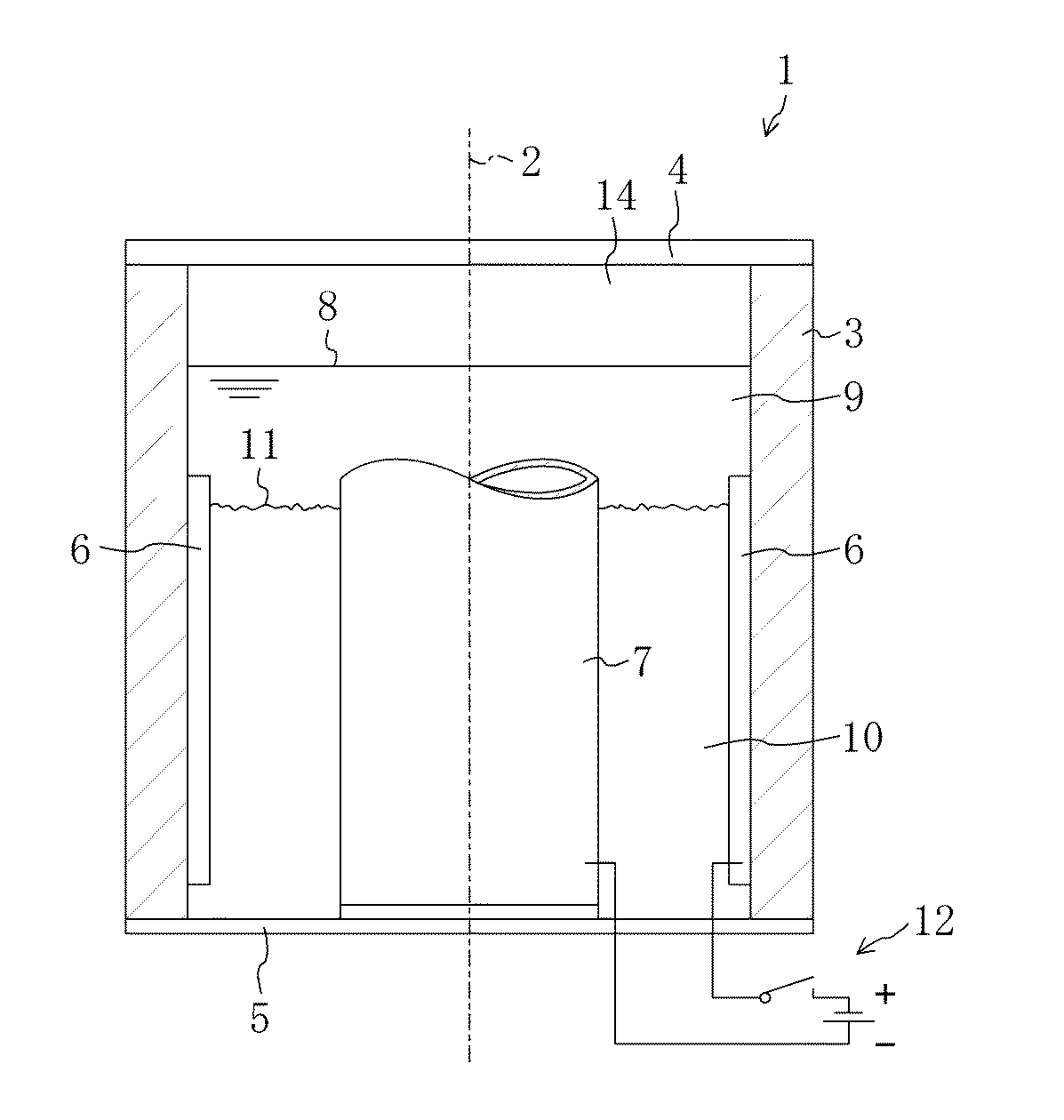
本発明の実施形態を同封の図面を参照しながら以下に説明する。図1は、酸水素ガス生成装置の概略図を示す。 Embodiments of the present invention will be described below with reference to the accompanying drawings. FIG. 1 shows a schematic diagram of an oxyhydrogen gas generator.
図1に示す装置は、中心軸2に関して回転可能かつ対称に設計された容器1を有し、上部カバー4および下部カバー5によって閉じられる管状ハウジング3を有する。装置全体は図示されているよりも長尺に形成されることが好ましい。
The device shown in FIG. 1 has a
ハウジング3の内壁には、環状外側電極6が設けられている。ハウジング3内部には管状内側電極7が置かれている。容器1には水位8まで水9が入っている。
An annular
電極6および7の間には、ゲル状のイオン交換体10が水位11まで入っている。
Between the
外側電極6は、例えば12Vカーバッテリ等の電源13のプラス極にスイッチ12を介して接続されている。電源13のマイナス極は内側電極7に接続されている。しかしながらこの極性は逆であってもよい。
The
図1に示す実施形態において、水位8はゲル状イオン交換体10の水位11よりも上にあり、上向きに開口する管状の内側電極7よりも上にある。電極7は閉じられていてもよい。電極7は水位8を超えて突出していてもよい。また、図示する実施形態において、ゲル状イオン交換体10の水位11は、外側電極6の上端部のすぐ下にある。しかしながら、この装置は水位11が電極6の上端部よりも上にくるように設計されていてもよい。内側電極7は下向きに閉じられていてもよいし、開いていてもよい。内側電極は下端部が開口していてもよいし、下部カバー5に封止接続されていてもよい。
In the embodiment shown in FIG. 1, the water level 8 is above the
スイッチ12が閉じられると容器1内で電解反応が起こり、負に帯電した電子およびイオンが陽極である外側電極6に引き付けられる。陽イオンは陰極である内側電極7へと流動する。このように、酸水素ガスが水位8と上部カバー4との間の空間14で生成される。これは特有の酸水素ガス生成に関する事柄である。この反応は実質的にイオン交換体10によって促進される。酸水素ガスは化学量論比で存在し、空間14から抜き取られる(図示せず)。これは不連続的(バッチ運転)または連続的に行ってもよい。生成された水素および酸素は、容器1の対応するデザインにより、別々に回収および排出することができる。
When the
イオン交換体10は、強酸性のゲル状イオン交換体であり、活性基としてスルホン酸基を有する。イオン交換体は一般化学式R−SO3−Hを有する。式中Rは基質、具体的には架橋ポリスチレン基質であり、SO3はスルホン酸活性基、Hは水素である。
The
イオン交換体10は流動状態で保たれていることが好ましい。これは好ましくはイオン交換体10を沈殿させないために行われる。イオン交換体は流動床プロセスによって流動状態に保たれていてもよい。イオン交換体が流動状態で保たれれば、ガス生成および電子流動が向上する。
The
さらに有利な技術成果によれば、イオン交換体は液体中に懸濁した状態で保たれている。これはイオン交換体または基礎イオン交換体材料が水9である液体中にそれ自体が懸濁状態で留まるように生成されるという点で好ましく行われる。
According to a further advantageous technical result, the ion exchanger is kept suspended in the liquid. This is preferably done in that the ion exchanger or basic ion exchanger material is produced so that it remains suspended in a liquid which is
本方法は連続的に行ってもよい。そのためにイオン交換体10は連続的に供給および排出されてもよい(図示せず)。排出されたイオン交換体は再生され、再び供給される。
The method may be performed continuously. For this purpose, the
本方法は多段階的に行ってもよい。 The method may be performed in multiple stages.
生成ガスは空間14から吸出してもよい。そのために空間14内に真空を発生させてもよい。さらに、上方へ漏出するガスはイオン交換体10を伴って流れるため、イオン交換体10を混合および拡散させることができる。
The generated gas may be sucked out of the
圧力および温度は、プロセスを理想的な効率で達成できるように設定することができる。 The pressure and temperature can be set so that the process can be achieved with ideal efficiency.
以下の表1に示す測定値は実際の実験によって算出されたものである。 The measured values shown in Table 1 below are calculated by actual experiments.
実験1は、イオン交換体を含まない水中で行った比較実験である。実験2では少量のイオン交換体を使用し、実験3では大量のイオン交換体を使用した。実験4では少量の塩酸をさらに追加した。
実験1では、1.0Aの電流を10.2Vの電圧で供給し、供給電力が10.2Wとなるようにする。このプロセスでは、10ml/分の酸水素ガスが生成される。これは時間あたりのエネルギー量1.8Wに相当する。このときの効率は(1.8:10.2=)0.176である。
In
イオン交換体を加えることにより、追加量に従ってアンペア数が3.0から7.5Aに増加するが、これに応じて電圧は9.2Vから6.5Vに減少する。生成された酸水素ガスの量は40ml/分から100ml/分に増加する。効率は0.260から0.370に増加する。 By adding the ion exchanger, the amperage increases from 3.0 to 7.5 A according to the added amount, but the voltage decreases accordingly from 9.2 V to 6.5 V. The amount of oxyhydrogen gas produced increases from 40 ml / min to 100 ml / min. Efficiency increases from 0.260 to 0.370.
実験4で少量の塩酸を加えることにより、アンペア数はさらに8.1Aに増加し、電圧はさらに5.7Vに減少する。生成された酸水素ガスの量はさらに115ml/分に増加し、効率は0.448に増加する。
By adding a small amount of hydrochloric acid in
図1に示す実験装置を使用したが、極性は逆にした。マイナス電極を形成するハウジング3は長さ116mm、内径26mmおよび外径28mmの管状に設計されている。プラス電極を形成する内側電極7は、長さ116mm、内径14mmおよび外径16mmの管状に設計されている。バッテリー充電器13は電源として使用され、DC電流を電圧12Vで発生させる。濃琥珀色の球体として入手できるAmberlit社のスチレン−DVBをイオン交換体として使用した。このイオン交換体の官能基はスルホン酸から形成される。内側電極7の内部には詰め物が充填されている(その他の添加物はなし)。
The experimental apparatus shown in FIG. 1 was used, but the polarity was reversed. The
実験を行う際、電極装置は50mlの飲料水で満たされる。これは2.75モルの物質量に相当する。電極装置全体が完全に「水中」に置かれるため、液交換が内側電極7の内部と、内側電極7とハウジング3との間の環状空間との間で、実際には内側電極7の上端部の上の空間と、その下端部の上つまり内側電極7の下端部と下部カバー5との間の空間の両方で生じる。上記飲料水のpHは7.0、導電性は266μS/cm(25℃)、硬度は5.4dH°である。DC電流が印加されると、イオン交換体の添加量に左右されるアンペア数、電圧、電力、標準体積としての酸水素ガス(KG)の時間あたりの生成量に関する表2に示す値が得られる。先に記載したイオン交換体を使用した。
In conducting the experiment, the electrode device is filled with 50 ml of drinking water. This corresponds to a substance amount of 2.75 mol. Since the entire electrode device is completely “underwater”, liquid exchange takes place between the inside of the inner electrode 7 and the annular space between the inner electrode 7 and the
1番目の実験ではイオン交換体を加えなかった。5.0ml/分の酸水素ガスが生成された。この量は1mlのイオン交換体を添加することによって2倍になる。1分間に生成される酸水素ガスの量はイオン交換体の量が増加するにつれて増加する。 In the first experiment, no ion exchanger was added. An oxyhydrogen gas of 5.0 ml / min was produced. This amount is doubled by adding 1 ml of ion exchanger. The amount of oxyhydrogen gas produced per minute increases as the amount of ion exchanger increases.
ハウジング3および内側電極7の長さを116mmから270mmに増加したこと以外は実施例2と同様の実験装置を使用した。実験装置のそれ以外の変更はしていない。得られた測定値は表3の通りである。
The same experimental apparatus as in Example 2 was used except that the length of the
本発明の方法によれば、電気分解において、例えば酸性カチオン交換体のような、生成ガスが特にイオン結合によって付着する物質を、具体的には水である液体に触媒およびドナーとして添加する。これにより、例えば水等の分解対象物質の分解を同義因子によって促進させることができる。添加する物質は酸、塩基またはイオン交換メンブレンのいずれでもない。固有の観点において、イオン交換体、とりわけカチオン交換樹脂および/またはアニオン交換樹脂は、例えば水素および酸素または酸水素ガスを生成するための水の電気分解のような、それ自体が周知である電気分解工程に添加されて触媒として作用し、電流フローを増加させる。また同時に、水素および/または酸素のドナーとして同工程の実施に貢献する。このように、上記実施形態によれば、例えば電流強度3,900C/分で0.6から0.85の効率を実現することができる。対応する装置は、14.6l/hの酸水素ガスを生成することができる。この酸水素ガス生成装置は、エンジンの構成要素であってもよく、エンジンに必要な酸水素ガスを特有の方法で生成する。このようにすると、必要量の酸水素ガスを連続的に生成することができるため、酸水素ガスの液化および貯蔵が不要となる。しかしながら、水素および酸素を別々に生成および使用することも可能である。 According to the method of the invention, in electrolysis, a substance to which the product gas adheres, in particular by ionic bonds, such as an acidic cation exchanger, is added as a catalyst and donor to a liquid, specifically water. Thereby, decomposition | disassembly of decomposition | disassembly object substances, such as water, can be accelerated | stimulated by a synonymous factor, for example. The substance to be added is neither an acid, a base nor an ion exchange membrane. In an inherent aspect, ion exchangers, in particular cation exchange resins and / or anion exchange resins, are electrolysis well known per se, such as, for example, electrolysis of water to produce hydrogen and oxygen or oxyhydrogen gas. Added to the process to act as a catalyst and increase current flow. At the same time, it contributes to the implementation of this process as a donor of hydrogen and / or oxygen. Thus, according to the above embodiment, for example, an efficiency of 0.6 to 0.85 can be realized at a current intensity of 3,900 C / min. A corresponding apparatus can produce 14.6 l / h oxyhydrogen gas. This oxyhydrogen gas generation device may be a component of the engine, and generates oxyhydrogen gas necessary for the engine by a specific method. In this way, since a necessary amount of oxyhydrogen gas can be continuously generated, liquefaction and storage of oxyhydrogen gas is not required. However, it is also possible to produce and use hydrogen and oxygen separately.
管状電極7の内部にフィラー材料、具体的には詰め物を入れてもよい。この材料または詰め物は酸で湿らせた状態であってもよく、好ましくは塩酸が用いられる。これにより、実施例1の実験4で記載したように収量が実質的に増加する。
A filler material, specifically, a filling may be placed inside the tubular electrode 7. This material or filling may be wetted with acid, preferably hydrochloric acid. This substantially increases the yield as described in
電解処理される液体は水であってもよい。しかしながら、例えば水素やその他の物質等の生成ガスを含むその他の液体を使用することも可能である。 The liquid to be electrolytically treated may be water. However, it is also possible to use other liquids containing product gases such as hydrogen or other substances.
Claims (10)
ハウジング内に、外側電極と、当該外側電極の内側に位置する管状の内側電極と、を配置する工程と、
前記外側電極と前記内側電極との間に、前記ガスが脱着可能に付着する非導電性イオン交換体を膜を介在させることなく配置する工程と、
前記内側電極の内部と、前記内側電極と前記ハウジングとの間の空間と、の間で液交換が生じるように、水位が当該内側電極よりも上になるまで前記ハウジングに水を入れる工程と、
前記外側電極及び前記内側電極に電圧を印加して前記水を電解分解する工程と、
電解反応により生成される前記ガスを前記水位より上方の空間を通じて回収する工程と、
を備えていることを特徴とする方法。A method for generating at least one of hydrogen gas and oxyhydrogen gas,
Disposing an outer electrode and a tubular inner electrode located inside the outer electrode in the housing;
Disposing a non-conductive ion exchanger to which the gas is detachably attached between the outer electrode and the inner electrode without interposing a membrane ;
Filling the housing with water until the water level is above the inner electrode so that liquid exchange occurs between the interior of the inner electrode and the space between the inner electrode and the housing;
Applying a voltage to the outer electrode and the inner electrode to electrolyze the water;
Recovering the gas produced by the electrolytic reaction through a space above the water level ;
A method characterized by comprising:
前記非導電性イオン交換体は酸性イオン交換体である方法。The method of claim 1, wherein
The method wherein the non-conductive ion exchanger is an acidic ion exchanger.
前記非導電性イオン交換体はゲル状である方法。The method according to claim 1 or 2,
The method wherein the non-conductive ion exchanger is in a gel form.
前記非導電性イオン交換体は触媒作用物質を含む方法。The method according to any one of claims 1 to 3, wherein
The method wherein the non-conductive ion exchanger comprises a catalytic agent.
前記非導電性イオン交換体は流動状態に保たれている方法。The method according to any one of claims 1 to 4, wherein
A method in which the non-conductive ion exchanger is kept in a fluid state.
前記非導電性イオン交換体は前記液体中に懸濁した状態で保たれている方法。The method according to any one of claims 1-5,
The method wherein the non-conductive ion exchanger is kept suspended in the liquid.
前記非導電性イオン交換体は連続的に供給される方法。The method according to any one of claims 1 to 6, wherein
The method in which the non-conductive ion exchanger is continuously supplied.
前記ハウジングと、
前記ハウジングを閉じる上部カバー及び下部カバーと、
前記ハウジング内に設けられた外側電極と、
前記ハウジング内に設けられ、前記外側電極の内側に位置する管状の内側電極と、
前記外側電極と前記内側電極との間に入れられた非導電性イオン交換体と、
を備え、
前記外側電極及び前記内側電極は、電源に接続されて陰極及び陽極を構成していることを特徴とする装置。An apparatus for carrying out the method according to claim 1,
The housing;
An upper cover and a lower cover for closing the housing;
An outer electrode provided in the housing;
A tubular inner electrode provided in the housing and positioned inside the outer electrode;
A non-conductive ion exchanger placed between the outer electrode and the inner electrode;
With
The outer electrode and the inner electrode are connected to a power source to form a cathode and an anode.
前記内側電極の内側に酸を含むフィラー材料が入れられている装置。The apparatus according to claim 8.
A device in which a filler material containing an acid is placed inside the inner electrode.
前記酸は塩酸である装置。The apparatus of claim 9.
An apparatus wherein the acid is hydrochloric acid.
Applications Claiming Priority (5)
| Application Number | Priority Date | Filing Date | Title |
|---|---|---|---|
| DE10355592 | 2003-11-28 | ||
| DE10355592.7 | 2003-11-28 | ||
| DE10359509.0 | 2003-12-18 | ||
| DE10359509A DE10359509B4 (en) | 2003-11-28 | 2003-12-18 | Production of gases, especially hydrogen and oxygen, comprises electrolysis of liquid, especially water, containing material which adsorbs gases |
| PCT/EP2004/013452 WO2005052214A2 (en) | 2003-11-28 | 2004-11-26 | Method and device for producing one or several gases |
Publications (2)
| Publication Number | Publication Date |
|---|---|
| JP2007512435A JP2007512435A (en) | 2007-05-17 |
| JP5094122B2 true JP5094122B2 (en) | 2012-12-12 |
Family
ID=34635114
Family Applications (1)
| Application Number | Title | Priority Date | Filing Date |
|---|---|---|---|
| JP2006540400A Expired - Fee Related JP5094122B2 (en) | 2003-11-28 | 2004-11-26 | Method and apparatus for generating one or more gases |
Country Status (8)
| Country | Link |
|---|---|
| US (1) | US8197666B2 (en) |
| EP (1) | EP1704268B1 (en) |
| JP (1) | JP5094122B2 (en) |
| KR (1) | KR101218952B1 (en) |
| AU (1) | AU2004293566B2 (en) |
| CA (1) | CA2547295C (en) |
| RU (1) | RU2385363C2 (en) |
| WO (1) | WO2005052214A2 (en) |
Families Citing this family (16)
| Publication number | Priority date | Publication date | Assignee | Title |
|---|---|---|---|---|
| US7521457B2 (en) * | 2004-08-20 | 2009-04-21 | Boehringer Ingelheim International Gmbh | Pyrimidines as PLK inhibitors |
| DE102005024619B4 (en) * | 2005-05-30 | 2016-10-27 | Franz Roiner | Process for the production of hydrogen |
| KR100925750B1 (en) * | 2007-09-20 | 2009-11-11 | 삼성전기주식회사 | Electrolyte solution for hydrogen generator and hydrogen generator including the same |
| FI121928B (en) * | 2008-10-08 | 2011-06-15 | Teknillinen Korkeakoulu | Electricity generation systems |
| CA2752707C (en) | 2009-02-17 | 2014-01-07 | Mcalister Technologies, Llc | Apparatus and method for controlling nucleation during electrolysis |
| JP5547753B2 (en) | 2009-02-17 | 2014-07-16 | マクアリスター テクノロジーズ エルエルシー | Apparatus and method for collecting gas during electrolysis |
| BRPI1008696A2 (en) | 2009-02-17 | 2016-03-08 | Mcalister Technologies Llc | electrolytic cell and method for using it. |
| US9040012B2 (en) | 2009-02-17 | 2015-05-26 | Mcalister Technologies, Llc | System and method for renewable resource production, for example, hydrogen production by microbial electrolysis, fermentation, and/or photosynthesis |
| US8075750B2 (en) | 2009-02-17 | 2011-12-13 | Mcalister Technologies, Llc | Electrolytic cell and method of use thereof |
| US20110094457A1 (en) * | 2009-09-11 | 2011-04-28 | Geo Firewall Sarl | System for regulating a hydrocarbon combustion process using a substantially stoichiometric mix of hydrogen and oxygen |
| US20110094459A1 (en) | 2009-09-11 | 2011-04-28 | Geo Firewall Sarl | Regulating a hydrocarbon combustion process using a set of data indicative of hydrocarbon fuel consumed corresponding to a monitored engine operating characteristic |
| US20110233069A1 (en) * | 2010-03-24 | 2011-09-29 | Rasirc | Method and system for electrochemical hydrogen generation |
| KR20130081578A (en) * | 2012-01-09 | 2013-07-17 | 삼성전자주식회사 | Electrically regenerative water softening apparatus and method of operating the same |
| DE202012012463U1 (en) | 2012-11-12 | 2013-02-25 | Jakob Propp | Electrolysis device for generating at least one reaction product and a system for providing the generated reaction product for a consumer |
| US9127244B2 (en) | 2013-03-14 | 2015-09-08 | Mcalister Technologies, Llc | Digester assembly for providing renewable resources and associated systems, apparatuses, and methods |
| US10390494B2 (en) * | 2016-01-20 | 2019-08-27 | Nano Evaporative Technologies, Inc. | Hydroponic electroculture system and methods of use |
Family Cites Families (18)
| Publication number | Priority date | Publication date | Assignee | Title |
|---|---|---|---|---|
| SU28739A1 (en) * | 1931-11-05 | 1932-12-31 | П.А. Герасимов | A device for the production of detonating gas for the operation in internal combustion engines by electrolysis of water |
| SU527197A1 (en) * | 1972-01-10 | 1976-09-05 | Electrodialyzer | |
| EP0023740B1 (en) * | 1979-08-07 | 1983-04-20 | Agfa-Gevaert N.V. | Rotary cross-cutting apparatus for cutting continuously moving webs |
| DE3118750C1 (en) * | 1981-05-12 | 1987-02-12 | Horst Ing.(grad.) 8459 Hirschbach Linn | Melting crucible for small quantities |
| JPS5992028A (en) * | 1982-11-18 | 1984-05-28 | Nippon Paint Co Ltd | Ion exchange treatment |
| FR2595679B1 (en) * | 1986-03-14 | 1988-05-13 | Atochem | PROCESS FOR THE JOINT MANUFACTURE OF HYDROGEN PEROXIDE AND ISOBUTENE |
| SU1460787A1 (en) * | 1986-07-04 | 1994-10-30 | Г.А. Плотников | Method and apparatus for contacting polydispersed ionite with liquid |
| WO1990015659A1 (en) * | 1989-06-16 | 1990-12-27 | Olin Corporation | Process for removing ionizable impurities from non-aqueous fluids |
| US5348683A (en) * | 1990-02-06 | 1994-09-20 | Olin Corporation | Chloric acid - alkali metal chlorate mixtures and chlorine dioxide generation |
| JP3095441B2 (en) * | 1990-12-26 | 2000-10-03 | ユニチカ株式会社 | Electrolytic cell and method of operating the same |
| JP3278909B2 (en) * | 1992-07-16 | 2002-04-30 | 株式会社豊田中央研究所 | Hydrogen generator |
| US5419816A (en) * | 1993-10-27 | 1995-05-30 | Halox Technologies Corporation | Electrolytic process and apparatus for the controlled oxidation of inorganic and organic species in aqueous solutions |
| JP2000265290A (en) * | 1999-03-18 | 2000-09-26 | Matsushita Refrig Co Ltd | Water electrolysis device |
| JP2001123288A (en) * | 1999-10-27 | 2001-05-08 | Tsukishima Kikai Co Ltd | Electrolytic apparatus |
| JP2002155387A (en) * | 2000-05-30 | 2002-05-31 | Mcl Engineering:Kk | Gaseous mixture generator and boiler using the gaseous mixture |
| JP2002066563A (en) * | 2000-08-31 | 2002-03-05 | Tokyo Yogyo Co Ltd | Active hydrogen storage water purifier |
| IL161529A0 (en) * | 2001-10-31 | 2004-09-27 | R & R Ventures Inc | Iontophoresis device |
| US6652719B1 (en) * | 2002-06-03 | 2003-11-25 | Skydon Corp. | Electrolysis system |
-
2004
- 2004-11-26 US US10/581,009 patent/US8197666B2/en active Active
- 2004-11-26 RU RU2006122945/15A patent/RU2385363C2/en not_active IP Right Cessation
- 2004-11-26 WO PCT/EP2004/013452 patent/WO2005052214A2/en not_active Ceased
- 2004-11-26 CA CA2547295A patent/CA2547295C/en not_active Expired - Fee Related
- 2004-11-26 KR KR1020067009723A patent/KR101218952B1/en not_active Expired - Fee Related
- 2004-11-26 JP JP2006540400A patent/JP5094122B2/en not_active Expired - Fee Related
- 2004-11-26 EP EP04819229.8A patent/EP1704268B1/en not_active Expired - Lifetime
- 2004-11-26 AU AU2004293566A patent/AU2004293566B2/en not_active Ceased
Also Published As
| Publication number | Publication date |
|---|---|
| RU2385363C2 (en) | 2010-03-27 |
| US8197666B2 (en) | 2012-06-12 |
| JP2007512435A (en) | 2007-05-17 |
| KR20060114334A (en) | 2006-11-06 |
| CA2547295A1 (en) | 2005-06-09 |
| AU2004293566B2 (en) | 2011-04-21 |
| AU2004293566A1 (en) | 2005-06-09 |
| WO2005052214A3 (en) | 2005-09-15 |
| US20070108065A1 (en) | 2007-05-17 |
| WO2005052214A2 (en) | 2005-06-09 |
| EP1704268A2 (en) | 2006-09-27 |
| EP1704268B1 (en) | 2018-05-02 |
| CA2547295C (en) | 2013-08-20 |
| RU2006122945A (en) | 2008-01-10 |
| KR101218952B1 (en) | 2013-01-14 |
Similar Documents
| Publication | Publication Date | Title |
|---|---|---|
| JP5094122B2 (en) | Method and apparatus for generating one or more gases | |
| EP0390158B1 (en) | Electrolysis cell | |
| CN105112934B (en) | A kind of preparation method of tetra-alkyl ammonium hydroxide | |
| JP2000104189A (en) | Production of hydrogen peroxide and electrolytic cell for production | |
| CN101962215B (en) | Plasma electrolytic catalysis method and device | |
| CN101506406A (en) | Electrode, method of manufacture and use thereof | |
| CN108411333A (en) | A method of preparing hydrogen peroxide using the hydrophobic cathodic reduction oxygen of acetylene black | |
| CN111547901A (en) | In-situ generation of hydrogen peroxide and ferrate coupled water treatment advanced purification device and treatment method | |
| CN109136973A (en) | A kind of non-precious metal doped molybdenum carbide hydrogen evolution electrode and its preparation method and application | |
| CN114481177B (en) | A reaction device and application of gas diffusion electrode combined with microchannel electrochemical preparation of hydrogen peroxide | |
| CN110468429B (en) | Activation method of silver electrode | |
| JP2005095808A (en) | Stirrer for hydrogen water production | |
| CN107512760A (en) | Electrolytic cell device of synchronous electricity life ozone and hydrogen peroxide and preparation method thereof, application | |
| CN110965071B (en) | A metal catalyst for electrochemical reduction of carbon dioxide and its preparation and application | |
| JPS63259093A (en) | Electrochemical method for recovery of metal rhodium from waste catalyst aqueous solution | |
| CN102021600A (en) | Method and device for producing potassium iodate through oxygen cathode non-diaphragm electrolysis | |
| CN113666367A (en) | Electrolytic tank for preparing graphite intercalation and preparation method of graphite intercalation | |
| Kolyagin et al. | Electrochemical reduction of oxygen to hydrogen peroxide in a gas-diffusion electrode based on mesoporous carbon | |
| US20160115605A1 (en) | System and method for selective electrochemical reduction of carbon dioxide employing an anodized silver electrode | |
| KR101741675B1 (en) | Method for electrochemical treatment of sewage and wastewater using conductive material | |
| CN103266329A (en) | Electrochemical method for synthesizing 2,2'-dichlorohydrazobenzene by use of supported catalyst ionic membrane | |
| Mazloum-Ardakani et al. | Enhanced electro-oxidation of urea based on nickel nanoparticle decorated reduced graphene oxide/PEDOT: PSS composite | |
| CN101864578A (en) | Method for preparing peroxymonosulfuric acid by sonoelectrochemistry | |
| Hu et al. | Electrohydrogenation of 4-amino-5-nitrosodimethyluracil with a foamed nickel cathode | |
| CN103996860A (en) | Graphite-polytetrafluoroethylene three-dimensional particle cathode of MFC (microbial fuel cell) synthesized on basis of hydrogen peroxide and preparation method |
Legal Events
| Date | Code | Title | Description |
|---|---|---|---|
| A621 | Written request for application examination |
Free format text: JAPANESE INTERMEDIATE CODE: A621 Effective date: 20070829 |
|
| A977 | Report on retrieval |
Free format text: JAPANESE INTERMEDIATE CODE: A971007 Effective date: 20091228 |
|
| A131 | Notification of reasons for refusal |
Free format text: JAPANESE INTERMEDIATE CODE: A131 Effective date: 20100112 |
|
| A521 | Request for written amendment filed |
Free format text: JAPANESE INTERMEDIATE CODE: A523 Effective date: 20100406 |
|
| A131 | Notification of reasons for refusal |
Free format text: JAPANESE INTERMEDIATE CODE: A131 Effective date: 20101116 |
|
| A521 | Request for written amendment filed |
Free format text: JAPANESE INTERMEDIATE CODE: A523 Effective date: 20110209 |
|
| A131 | Notification of reasons for refusal |
Free format text: JAPANESE INTERMEDIATE CODE: A131 Effective date: 20111108 |
|
| A521 | Request for written amendment filed |
Free format text: JAPANESE INTERMEDIATE CODE: A523 Effective date: 20120207 |
|
| TRDD | Decision of grant or rejection written | ||
| A01 | Written decision to grant a patent or to grant a registration (utility model) |
Free format text: JAPANESE INTERMEDIATE CODE: A01 Effective date: 20120821 |
|
| A01 | Written decision to grant a patent or to grant a registration (utility model) |
Free format text: JAPANESE INTERMEDIATE CODE: A01 |
|
| A61 | First payment of annual fees (during grant procedure) |
Free format text: JAPANESE INTERMEDIATE CODE: A61 Effective date: 20120918 |
|
| R150 | Certificate of patent or registration of utility model |
Ref document number: 5094122 Country of ref document: JP Free format text: JAPANESE INTERMEDIATE CODE: R150 Free format text: JAPANESE INTERMEDIATE CODE: R150 |
|
| FPAY | Renewal fee payment (event date is renewal date of database) |
Free format text: PAYMENT UNTIL: 20150928 Year of fee payment: 3 |
|
| R250 | Receipt of annual fees |
Free format text: JAPANESE INTERMEDIATE CODE: R250 |
|
| R250 | Receipt of annual fees |
Free format text: JAPANESE INTERMEDIATE CODE: R250 |
|
| R250 | Receipt of annual fees |
Free format text: JAPANESE INTERMEDIATE CODE: R250 |
|
| R250 | Receipt of annual fees |
Free format text: JAPANESE INTERMEDIATE CODE: R250 |
|
| R250 | Receipt of annual fees |
Free format text: JAPANESE INTERMEDIATE CODE: R250 |
|
| R250 | Receipt of annual fees |
Free format text: JAPANESE INTERMEDIATE CODE: R250 |
|
| LAPS | Cancellation because of no payment of annual fees |