JP5073332B2 - Image forming apparatus - Google Patents
Image forming apparatus Download PDFInfo
- Publication number
- JP5073332B2 JP5073332B2 JP2007070572A JP2007070572A JP5073332B2 JP 5073332 B2 JP5073332 B2 JP 5073332B2 JP 2007070572 A JP2007070572 A JP 2007070572A JP 2007070572 A JP2007070572 A JP 2007070572A JP 5073332 B2 JP5073332 B2 JP 5073332B2
- Authority
- JP
- Japan
- Prior art keywords
- brush
- toner
- image
- capturing
- image forming
- Prior art date
- Legal status (The legal status is an assumption and is not a legal conclusion. Google has not performed a legal analysis and makes no representation as to the accuracy of the status listed.)
- Expired - Fee Related
Links
Images


Classifications
-
- G—PHYSICS
- G03—PHOTOGRAPHY; CINEMATOGRAPHY; ANALOGOUS TECHNIQUES USING WAVES OTHER THAN OPTICAL WAVES; ELECTROGRAPHY; HOLOGRAPHY
- G03G—ELECTROGRAPHY; ELECTROPHOTOGRAPHY; MAGNETOGRAPHY
- G03G21/00—Arrangements not provided for by groups G03G13/00 - G03G19/00, e.g. cleaning, elimination of residual charge
- G03G21/0005—Arrangements not provided for by groups G03G13/00 - G03G19/00, e.g. cleaning, elimination of residual charge for removing solid developer or debris from the electrographic recording medium
- G03G21/0035—Arrangements not provided for by groups G03G13/00 - G03G19/00, e.g. cleaning, elimination of residual charge for removing solid developer or debris from the electrographic recording medium using a brush; Details of cleaning brushes, e.g. fibre density
Landscapes
- Physics & Mathematics (AREA)
- General Physics & Mathematics (AREA)
- Cleaning In Electrography (AREA)
- Electrostatic Charge, Transfer And Separation In Electrography (AREA)
Description
本発明は、転写工程を通過した後の像担持体の表面に付着しているトナーをブラシ内に一時的に捕捉した後、所定のタイミングでブラシ内から像担持体の表面に逆戻りさせるプリンタ、複写機、ファクシミリ等の画像形成装置に関するものである。 The present invention relates to a printer that temporarily captures the toner adhering to the surface of the image carrier after passing through the transfer step in the brush and then returns the toner to the surface of the image carrier from the brush at a predetermined timing. The present invention relates to an image forming apparatus such as a copying machine or a facsimile.
一般に、電子写真方式の画像形成装置においては、次のようなプロセスで画像を形成する。即ち、まず、帯電装置によって一様帯電せしめた感光体等の像担持体に対して露光走査などを施して静電潜像を形成し、この静電潜像を現像装置によって現像する。次いで、現像によって得られたトナー像を、像担持体上から記録紙等の記録部材に直接転写するか、あるいは中間転写体を介して記録部材に転写する。かかるプロセスにおいて、転写工程を経た後の像担持体の表面には、記録部材や中間転写体に転写されなかった転写残トナーが付着している。一般的な画像形成装置においては、この転写残トナーをクリーニングブレード等によって像担持体から除去した後、現像装置内に再搬送してリサイクルするクリーニングリサイクル機構を備えていることが多い。 In general, an electrophotographic image forming apparatus forms an image by the following process. That is, first, an electrostatic latent image is formed by subjecting an image carrier such as a photosensitive member uniformly charged by a charging device to exposure scanning, and the electrostatic latent image is developed by a developing device. Next, the toner image obtained by development is directly transferred from the image bearing member to a recording member such as recording paper, or transferred to the recording member via an intermediate transfer member. In such a process, the transfer residual toner that has not been transferred to the recording member or the intermediate transfer member adheres to the surface of the image carrier after the transfer step. A general image forming apparatus is often provided with a cleaning / recycling mechanism that removes the transfer residual toner from the image carrier with a cleaning blade or the like and then re-transports and recycles the toner inside the developing device.
しかしながら、この種のクリーニングリサイクル機構は、像担持体の表面から掻き取った転写残トナーを現像装置内に送るためのトナー搬送機構を必要とすることから、構成が複雑になって画像形成装置の大型化を招くという欠点があった。 However, this type of cleaning / recycling mechanism requires a toner transport mechanism for sending the transfer residual toner scraped off from the surface of the image carrier into the developing device. There was a drawback of increasing the size.
クリーニングリサイクル機構を用いることなく、転写残トナーを処理することが可能な画像形成装置としては、転写残トナーをブラシ部材によって一時捕捉するものが知られている(例えば特許文献1に記載のもの)。この種の画像形成装置は、ブラシ部材によって像担持体の表面から掻き取った転写残トナーをブラシ内に一時的に捕捉する一時捕捉処理を実施する。次いで、バイアス条件の変更などによってトナーをブラシ内から像担持体の表面に戻す戻し処理を、プリントジョブ終了後などの所定のタイミングで実施する。そして、像担持体の表面から現像装置の現像剤担持体(例えば現像ローラ)内に転移させることで、転写残トナーを最終的に現像装置内に回収する。かかる構成では、搬送スクリュウや搬送ベルトなどといった複雑なトナー搬送機構を必要としないため、装置の小型化や低コスト化を図ることができる。 As an image forming apparatus capable of processing untransferred toner without using a cleaning recycling mechanism, an apparatus that temporarily captures untransferred toner with a brush member is known (for example, one described in Patent Document 1). . This type of image forming apparatus performs a temporary capturing process in which the transfer residual toner scraped from the surface of the image carrier by the brush member is temporarily captured in the brush. Next, a return process for returning the toner from the brush to the surface of the image carrier by changing the bias condition or the like is performed at a predetermined timing such as after the end of the print job. Then, transfer residual toner is finally collected in the developing device by transferring from the surface of the image bearing member into a developer carrying member (for example, a developing roller) of the developing device. In such a configuration, a complicated toner transport mechanism such as a transport screw or a transport belt is not required, and thus the apparatus can be reduced in size and cost.
しかしながら、この種の画像形成装置においては、トナーが長期間に渡ってブラシ内に徐々に蓄積していくことで、異常画像を発生させることがあった。具体的には、複数の起毛から構成されるブラシによって像担持体の表面から掻き取られたトナーは、ブラシ内における各起毛の間に取り込まれる。そして、取り込まれたトナーの大半は、ブラシ先端部に留まった後、戻し処理において像担持体の表面にスムーズに逆転移する。ところが、ブラシ内に取り込まれた後、ブラシの挙動の影響などを受けてブラシの奥深くに入り込んでしまうトナーも少なからず発生する。かかるトナーは、次に説明する理由により、ブラシの先端側にスムーズに移動することができない。即ち、戻し処理において、ブラシと像担持体との接触部で両者間に形成される電気力線は、像担持体の表面に対する垂線に沿ってほぼ真っ直ぐに延びている。これに対し、像担持体の表面に接触している起毛は、像担持体の表面移動に追従して撓んでいる。ブラシの奥深くの各起毛間に留まっているトナーは、電気力線に沿って真っ直ぐに移動しようとすると、撓んでいる起毛の側面にぶつかってしまうため、先端側にスムーズに移動することができないのである。 However, in this type of image forming apparatus, the toner gradually accumulates in the brush over a long period of time, so that an abnormal image may be generated. Specifically, toner scraped from the surface of the image carrier by a brush composed of a plurality of raised hairs is taken in between the raised hairs in the brush. Then, most of the taken-in toner stays at the tip of the brush and then smoothly reversely transitions to the surface of the image carrier in the returning process. However, after being taken into the brush, there is a considerable amount of toner that penetrates deep into the brush due to the influence of the behavior of the brush. Such toner cannot move smoothly to the tip side of the brush for the following reason. That is, in the returning process, the electric lines of force formed between the brush and the image carrier at the contact portion extend substantially straight along a perpendicular to the surface of the image carrier. On the other hand, the raised portions that are in contact with the surface of the image carrier are bent following the movement of the surface of the image carrier. If the toner staying between the brushed parts in the deep part of the brush tries to move straight along the lines of electric force, it will collide with the side surface of the brushed brushed part, so it cannot move smoothly to the tip side. is there.
このような理由により、ブラシの根元側ではトナーが長期間に渡って徐々に蓄積していき、やがて種々の要因によって異常画像を発生させる。 For this reason, toner gradually accumulates over a long period of time on the base side of the brush, and an abnormal image is generated due to various factors.
例えば、像担持体の表面を一様帯電せしめる帯電部材としてブラシ部材を兼用している場合には、ブラシ内に蓄積したトナーがブラシと像担持体との間の放電を不安にして帯電ムラを引き起こす。そして、これにより、濃度ムラなどの異常画像を発生させる。 For example, when the brush member is also used as a charging member that uniformly charges the surface of the image carrier, the toner accumulated in the brush causes uneven charging due to anxiety of the discharge between the brush and the image carrier. cause. Thus, an abnormal image such as density unevenness is generated.
また例えば、ブラシ内に多量のトナーが蓄積すると、ブラシの挙動の影響を受けて多量のトナーが一時捕捉処理中であるにもかかわらず、像担持体にまとまって逆転移してしまうことがある。すると、そのトナーが後の帯電工程において像担持体の一様帯電を阻害して帯電ムラを引き起こしたり、潜像書込工程において像担持体への書込不良を引き起こしたりする。 Further, for example, if a large amount of toner accumulates in the brush, it may be reversely transferred to the image carrier even though the large amount of toner is being temporarily captured due to the influence of the behavior of the brush. As a result, the toner inhibits uniform charging of the image carrier in the subsequent charging process and causes uneven charging, or causes defective writing on the image carrier in the latent image writing process.
本発明は、以上の背景に鑑みなされたものであり、その目的とするところは、一時捕捉したトナーをブラシ内に多量に蓄積させることによる異常画像の発生を抑えることができる画像形成装置を提供することである。 The present invention has been made in view of the above background, and an object of the present invention is to provide an image forming apparatus capable of suppressing the occurrence of abnormal images caused by accumulating a large amount of temporarily captured toner in a brush. It is to be.
上記目的を達成するために、請求項1の発明は、像担持体の移動する表面にトナー像を形成する像形成手段と、トナー像を該像担持体の表面から転写体に転写する転写手段と、該表面の移動方向における全領域のうち、該転写手段による転写工程を通過した後の領域、に対して、ブラシ部材のブラシを接触させながら、該領域に付着しているトナーを複数の起毛からなる該ブラシ内に一時的に捕捉する一時捕捉処理を実施した後、所定のタイミングで該ブラシ内から該表面に逆戻りさせる戻し処理を実施するトナー一時捕捉手段とを備える画像形成装置であって、上記戻し処理において、上記領域に接触している状態の上記起毛の長さ方向における中心部の撓み方向を、少なくとも一時的に上記一時捕捉処理のときとは逆方向にし、上記ブラシ部材として、回転自在に支持される回転軸部材と、該回転軸部材の外周面に立設せしめられた複数の上記起毛からなるローラ状のブラシとを具備するブラシローラを用い、該ブラシローラを該像担持体との接触位置で該像担持体と同じ方向に移動させるように回転駆動する駆動手段、及び、該ブラシと上記像担持体との間の電界の向きを変化させる電界変化手段、を設け、上記一時捕捉処理では、トナーを該像担持体の表面から該ブラシ内に取り込む向きの該電界を形成するための捕捉バイアスを該ブラシローラに印加する一方で、上記戻し処理では、該ブラシ内のトナーを該像担持体の表面に吐き出す向きの該電界を形成するための吐き出しバイアスを該ブラシローラに印加する処理を実施するように該電界変化手段を構成し、且つ、該ブラシの線速を上記像担持体の表面移動速度の1/2以下にする駆動速度で上記ブラシローラを回転させながら、該戻し処理を実施させるようにしたことを特徴とするものである。
また、請求項2の発明は、請求項1に記載の画像形成装置において、上記戻し処理にて、上記電界として交番電界を形成させるように、上記電界変化手段を構成したことを特徴とするものである。
また、請求項3の発明は、請求項1又は2に記載の画像形成装置において、上記像担持体の表面の移動方向における非画像領域が上記ブラシとの接触位置を通過しているときに、上記戻し処理を実施させるようにしたことを特徴とするものである。
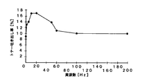
また、請求項4の発明は、請求項2に記載の画像形成装置であって、上記交番電界の周波数が50[Hz]以下であることを特徴とするものである。
また、請求項5の発明は、請求項1乃至4の何れかに記載の画像形成装置において、上記像担持体の表面と上記ブラシとの線速差を変化させることで、上記中心部の撓み方向を上記一時捕捉処理と上記戻し処理とで異ならせるようにしたことを特徴とするものである。
また、請求項6の発明は、請求項1乃至5の何れかに記載の画像形成装置において、上記ブラシローラのブラシの上記像担持体に対する食い込み量を変化させる食い込み量変化手段を設け、上記戻し処理のときには、上記一時捕捉処理のときよりも該食い込み量を小さくするようにしたことを特徴とするものである。
In order to achieve the above object, the invention of
According to a second aspect of the present invention, in the image forming apparatus according to the first aspect, the electric field changing means is configured to form an alternating electric field as the electric field in the return process. It is.
According to a third aspect of the present invention, in the image forming apparatus according to the first or second aspect, when the non-image area in the moving direction of the surface of the image carrier passes through the contact position with the brush, The return processing is performed.
The invention of
According to a fifth aspect of the present invention, in the image forming apparatus according to any one of the first to fourth aspects, the center portion is bent by changing a linear velocity difference between the surface of the image carrier and the brush. The direction is made different between the temporary capture process and the return process.
According to a sixth aspect of the present invention, there is provided the image forming apparatus according to any one of the first to fifth aspects, further comprising a biting amount changing unit that changes a biting amount of the brush roller with respect to the image carrier. In the process, the amount of biting is made smaller than that in the temporary capture process.
これらの発明においては、戻し処理でブラシの起毛の中心部を一時捕捉処理のときとは逆方向に撓ませていく途中で、起毛に対してブラシと像担持体との間の電気力線にほぼ沿った姿勢をとらせる。そして、このときに、ブラシの奥深くに入り込んだトナーを電気力線に沿ってスムーズに先端側に移動させる。更に、撓み方向を逆転させるという起毛の中心部の大きな挙動により、起毛に付着しているトナーをふるい落とすことで、トナーの先端側へのスムーズな移動を助長する。これらの結果、ブラシの奥深くに入り込んだトナーを戻し処理で迅速に像担持体の表面に戻すことが可能になる。かかる構成では、ブラシ内にトナーを蓄積させ難くすることが可能になるので、多量のトナーの蓄積による異常画像の発生を抑えることができる。 In these inventions, the center of the brushed brush is bent in the reverse direction in the returning process in the direction opposite to that in the temporary capturing process, and the electric force lines between the brush and the image carrier are raised against the raised brush. The posture is almost along. At this time, the toner that has entered deep into the brush is smoothly moved to the tip side along the lines of electric force. Further, due to the large behavior of the center part of the raising that reverses the bending direction, the toner adhering to the raising is screened off, thereby facilitating the smooth movement of the toner toward the tip side. As a result, the toner that has entered deep inside the brush can be quickly returned to the surface of the image carrier by the return process. In such a configuration, it is possible to make it difficult to accumulate toner in the brush, and thus it is possible to suppress the occurrence of abnormal images due to accumulation of a large amount of toner.
以下、本発明を適用した画像形成装置として、電子写真方式のカラーレーザープリンタ(以下、単にプリンタという)の一実施形態について説明する。
まず、本実施形態に係るプリンタの基本的な構成について説明する。図1は、本実施形態に係るプリンタの要部を示す概略構成図である。このプリンタは、イエロー,マゼンダ,シアン,ブラック(以下、Y,M,C,Kと記す)の各色のトナー像を形成するための4つのプロセスユニット1Y,M,C,Kを備えている。また、光書込ユニット50、レジストローラ対54、転写ユニット60等も備えている。各符号の末尾に付された添字Y,M,C,Kは、それぞれイエロー,マゼンダ,シアン,ブラック用の部材であることを示す。
Hereinafter, as an image forming apparatus to which the present invention is applied, an embodiment of an electrophotographic color laser printer (hereinafter simply referred to as a printer) will be described.
First, a basic configuration of the printer according to the present embodiment will be described. FIG. 1 is a schematic configuration diagram illustrating a main part of the printer according to the present embodiment. The printer includes four process units 1Y, M, C, and K for forming toner images of respective colors of yellow, magenta, cyan, and black (hereinafter referred to as Y, M, C, and K). An
潜像形成手段たる光書込ユニット50は、Y,M,C,Kの各色に対応する4つのレーザーダイオードからなる光源、正六面体のポリゴンミラー、これを回転駆動するためのポリゴンモータ、fθレンズ、レンズ、反射ミラー等を有している。レーザーダイオードから射出されたレーザー光Lは、ポリゴンミラーの何れか1つの面で反射してポリゴンミラーの回転に伴って偏向せしめられながら、後述する4つの感光体のうちの何れかに到達する。4つのレーザーダイオードからそれぞれ射出されるレーザー光Lにより、4つの感光体Y,M,C,Kの表面がそれぞれ光走査される。
The
プロセスユニット1Y,M,C,Kは、潜像担持体としてのドラム状の感光体3Y,M,C,K、これらにそれぞれ個別に対応する現像装置40Y,M,C,Kなどを有している。感光体3Y,M,C,Kは、アルミ等の素管に有機感光層が被覆されたものであり、図示しない駆動手段によって所定の線速で図中時計回り方向に回転駆動せしめられる。そして、図示しないパーソナルコンピュータ等から送られてくる画像情報に基づいて変調されたレーザー光Lを発する光書込ユニット50により、暗中にて光走査されて、Y,M,C,K用の静電潜像を担持する。
The
図2は、4つのプロセスユニット1Y,M,C,Kのうち、K用のプロセスユニット1Kをその周囲構成とともに示す拡大構成図である。同図において、K用のプロセスユニット1Kは、感光体3K、帯電ローラ7K、図示しない除電ランプ、ブラシ部材たるトナー捕捉ブラシローラ15K、現像手段たる現像装置40K等を、1つのユニットとして共通のユニットケーシング(保持体)に保持させて、プリンタ本体に対して着脱可能にしたものである。
FIG. 2 is an enlarged configuration diagram showing the
被帯電体であり且つ像担持体であるK用の感光体3Kは、アルミニウム素管からなる導電性基体の表面に、負帯電性の有機光光導電物質(OPC)からなる感光層が被覆された直径24[mm]程度のドラムであり、図示しない駆動手段によって所定の線速で図中時計回り方向に回転駆動せしめられる。
The
帯電ローラ7Kは、金属製の回転軸部材の周面に、導電性ゴム等からなる導電性ローラ部が被覆されたものであり、回転軸部材を中心にして図示しない駆動手段によって図中反時計回り方向に回転駆動されながら感光体3Kに接触して帯電ニップを形成している。帯電ローラ7Kの金属製の回転軸部材には、帯電電源101によって帯電バイアスが印加される。そして、帯電ローラ7Kと感光体3Kとの間に放電が発生することで、感光体3Kの表面が負極性に一様帯電せしめられる。
The charging
一様帯電せしめられたK用の感光体3Kの表面には、上述した光書込ユニット(50)による光走査でK用の静電潜像(負極性で且つ電位が地肌部よりも低い)が形成され、この静電潜像はK用の現像装置40KによってKトナー像に現像される。
On the surface of the uniformly charged
K用の現像装置40Kは、ケーシング41Kに設けられた開口から周面の一部を露出させる現像ローラ42Kを有している。この現像ローラ42Kは、ケーシング4K内に収容されている図示しないKトナーを周面に担持しながら回転する。現像ローラ42Kの表面に担持されたKトナーは、現像ローラ42Kの回転に伴って、現像ローラ42Kと感光体3Kとが対向あるいは接触する現像領域に搬送される。
The developing
この現像領域では、現像電源102から出力される負極性の現像バイアスが印加される現像ローラ42Kと、感光体3Kの静電潜像との間に、負極性のKトナーをローラ側から潜像側に静電移動させる現像ポテンシャルが作用する。また、現像ローラ42Kと感光体3Yの一様帯電箇所(地肌部)との間に、負極性のKトナーを地肌部側からローラ側に静電移動させる非現像ポテンシャルが作用する。現像ローラ42K上のKトナーは、現像ポテンシャルの作用によってローラ上から離脱して感光体3Kの静電潜像に転移する。この転移により、感光体3K上の静電潜像がKトナー像に現像される。このKトナーは、感光体3Kの回転に伴って、後述する転写ユニットの中間転写ベルト61上に1次転写される。
In this developing area, negative K toner is applied from the roller side to the latent image between the developing
1次転写ニップを通過した後、帯電ローラ7Kとの当接位置や上述の現像領域に進入する前の感光体3K表面には、トナー捕捉ブラシローラ15Kが当接して捕捉ニップを形成している。このトナー捕捉ブラシローラ15Kは、図示しない軸受けによって回転自在に支持される金属製の回転軸部材と、これの周面に立設せしめられた導電性材料からなる複数の起毛によって構成されるブラシとを有しており、このブラシの先端部を感光体3Kに当接させながら、図中反時計回り方向に回転駆動される。
After passing through the primary transfer nip, the toner catching
トナー捕捉ブラシローラ15Kの回転軸部材には、回収電源103によってバイアスが印加される。この回収電源103は、トナー捕捉ブラシローラ15Kに印加するバイアスを変化させることができる。
A bias is applied by the
1次転写ニップを通過した後の感光体3Kの表面は、1次転写ニップにおける転写電流の影響により、概ね0〜−20[V]まで電位を減衰させているとともに、転写残トナーを付着させている。回収電源103は、感光体3Kの表面の周方向における全領域のうち、トナー像を担持していた領域、がトナー捕捉ブラシローラ15Kとの接触位置を通過する期間には、交流電圧とプラス極性の直流電圧との重畳からなる捕捉バイアスをトナー捕捉ブラシローラ15Kに印加する。僅かにマイナス極性(トナーの正規帯電極性)に帯電している転写残トナーは、ブラシのプラス極性の直流成分に引かれて、感光体3Kからブラシ内に取り込まれる。即ち、本プリンタにおいては、回収電源103がトナー捕捉ブラシローラ15Kに捕捉バイアスを印加することで、感光体3Kに付着しているトナーを複数の起毛からなるブラシ内に一時的に捕捉する一時捕捉処理を実施する。
The surface of the
一方、回収電源103は、例えばプリントジョブ後や、連続プリントモードにおける紙間対応期間など、感光体3Kの表面におけるトナー像を担持していなかった非画像領域がトナー捕捉ブラシローラ15Kとの接触位置を通過する期間に、戻し処理を実施する。具体的には、図3に示すように、交流電圧とマイナス極性の直流電圧との重畳からなる吐き出しバイアスをトナー捕捉ブラシローラ15Kに印加する。これにより、マイナス極性の転写残トナーがブラシのマイナス極性の直流成分に反発して、ブラシ内から感光体3Kの表面に逆転移する。このとき、現像電源102は、現像ローラ42Kをアースに接続する。逆転移によって感光体3Kの表面に戻されたトナーは、上述の現像領域にて感光体3Kから現像ローラ42Kに転移して、現像装置40K内に回収される。
On the other hand, the
K用のプロセスユニット1Kについて説明してきたが、他色用のプロセスユニット1Y,M,CはK用のプロセスユニット1Kと同様の構成になっているので説明を省略する。
The
先に示した図1において、各色のプロセスユニット1Y,M,C,Kの下方には、転写ユニット60が配設されている。この転写ユニット60は、無端状の中間転写ベルト61を、複数の張架ローラによって張架しながら、図中反時計回り方向に無端移動せしめる。複数の張架ローラとは、具体的には、従動ローラ62、駆動ローラ63、4つの1次転写バイアスローラ66Y,M,C,K等のことである。
In FIG. 1 shown above, a
従動ローラ62、1次転写バイアスローラ66Y〜K、駆動ローラ63は、何れも中間転写ベルト61の裏面(ループ内周面)に接触している。そして、4つの1次転写バイアスローラ66Y,M,C,Kは、金属製の芯金にスポンジ等の弾性体が被覆されたローラであり、Y,M,C,K用の感光体3Y,M,C,Kに向けて押圧されて、中間転写ベルト61を挟み込んでいる。これにより、4つの感光体3Y,M,C,Kと中間転写ベルト61とがベルト移動方向において所定の長さで接触するY,M,C,K用の4つの1次転写ニップが形成されている。
The driven
4つの1次転写バイアスローラ66Y,M,C,Kの芯金には、それぞれ図示しない転写バイアス電源によって定電流制御される1次転写バイアスが印加されている。これにより、4つの1次転写バイアスローラ66Y,M,C,Kを介して中間転写ベルト61の裏面に転写電荷が付与され、各1次転写ニップにおいて中間転写ベルト61と感光体3Y,M,C,Kとの間に転写電界が形成される。なお、本プリンタにおいては、1次転写手段として1次転写バイアスローラ66Y,M,C,Kを設けているが、ローラに代えて、ブラシやブレード等のものを用いてもよい。また、転写チャージャーなどを用いてもよい。
A primary transfer bias that is constant current controlled by a transfer bias power source (not shown) is applied to the cores of the four primary
各色の感光体3Y,M,C,K上に形成されたY,M,C,Kトナー像は、各色の1次転写ニップで中間転写ベルト61上に重ね合わせて転写される。これにより、中間転写ベルト61上には4色重ね合わせトナー像(以下、4色トナー像という)が形成される。
The Y, M, C, and K toner images formed on the
中間転写ベルト61における駆動ローラ63に対する掛け回し箇所には、2次転写バイアスローラ67がベルトおもて面側から当接しており、これによって2次転写ニップが形成されている。この2次転写バイアスローラ67には、図示しない電源や配線からなる電圧印加手段によって2次転写バイアスが印加されている。これにより、2次転写バイアスローラ67と接地された2次転写ニップ裏側ローラ64との間に2次転写電界が形成されている。中間転写ベルト61上に形成された4色トナー像は、ベルトの無端移動に伴って2次転写ニップに進入する。
A secondary transfer bias roller 67 is in contact with the driving
本プリンタは、図示しない給紙カセットを備えており、その中に記録紙Pを複数枚重ねた記録紙束の状態で収容している。そして、一番上の記録紙Pを所定のタイミングで給紙路に送り出す。送り出された記録紙Pは、給紙路の末端に配設されたレジストローラ対54のレジストニップ内に挟み込まれる。 The printer includes a paper feed cassette (not shown), and accommodates a recording paper bundle in which a plurality of recording papers P are stacked therein. Then, the uppermost recording paper P is sent out to the paper feed path at a predetermined timing. The fed recording paper P is sandwiched in a registration nip of a registration roller pair 54 disposed at the end of the paper feed path.
レジストローラ対54は、給紙カセットから送られてきた記録紙Pをレジストニップに挟み込むために両ローラを回転駆動させているが、記録紙Pの先端を挟み込むとすぐに両ローラの回転駆動を停止させる。そして、記録紙Pを中間転写ベルト61上の4色トナー像に同期させ得るタイミングで2次転写ニップに向けて送り出す。2次転写ニップでは、中間転写ベルト61上の4色トナー像が2次転写電界やニップ圧の作用によって記録紙P上に一括2次転写されて、記録紙Pの白色と相まってフルカラー画像となる。
The registration roller pair 54 rotates both rollers in order to sandwich the recording paper P sent from the paper feed cassette into the registration nip. However, as soon as the leading edge of the recording paper P is sandwiched, both rollers rotate. Stop. Then, the recording paper P is fed toward the secondary transfer nip at a timing at which the recording paper P can be synchronized with the four-color toner image on the
このようにしてフルカラー画像が形成された記録紙Pは、2次転写ニップから排出された後、図示しない定着装置に送られてフルカラー画像が定着せしめられる。 The recording paper P on which the full-color image is formed in this manner is discharged from the secondary transfer nip, and then sent to a fixing device (not shown) to fix the full-color image.
2次転写ニップを通過した後の中間転写ベルト61表面に付着している2次転写残トナーは、ベルトクリーニング装置68によってベルト表面から除去される。
The secondary transfer residual toner adhering to the surface of the
以上の基本的な構成を有する本プリンタでは、4つのプロセスユニット1Y,M,C,Kや光書込ユニットなどが、像担持体たる感光体の移動する表面にトナー像を形成する像形成手段として機能している。また、トナー捕捉ブラシローラ(例えば図2の15K)や回収電源103などが、一時捕捉処理や戻し処理を実施するトナー一時捕捉手段として機能している。
In the printer having the above-described basic configuration, the four
次に、本プリンタの特徴的な構成について説明する。
本プリンタは、上述の戻し処理において、感光体3Kに接触している状態のトナー捕捉ブラシローラにおける起毛の長さ方向における中心部の撓み方向を、少なくとも一時的に上記一時捕捉処理のときとは逆方向にするようになっている。具体的には、K用のプロセスユニット1Kを例にすると、図4に示すように、一時捕捉処理のときには、トナー捕捉ブラシローラ15Kのブラシを構成する起毛16Kを、その根元よりも先端を感光体3Kの表面移動方向の上流側に位置させる姿勢で撓ませる。より詳しくは、起毛16Kの長さ方向の中心点P1を、先端点P2と根元点P3とを結ぶ仮想直線L1よりも感光体3Kの表面移動方向下流側に位置させるように、起毛16Kの長さ方向における中心部を表面移動方向下流側に向けて撓ませる。一方、戻し処理のときには、図5に示すように、少なくとも一時的に起毛16Kを、一時捕捉処理のときとは逆方向に撓ませる。より詳しくは、起毛16Kの中心点P1を仮想直線L1よりも感光体の表面移動方向上流側に位置させるように、起毛16Kの中心部を表面移動方向上流側に向けて撓ませる。
Next, a characteristic configuration of the printer will be described.
In the above-described returning process, the printer performs at least temporarily the bending direction of the central portion in the length direction of the raised brush in the toner capturing brush roller in contact with the
このような戻し処理においては、起毛16Kの中心部を一時捕捉処理のときとは逆方向に撓ませていく途中で、図6に示すように、対して感光体3Kの表面に対する垂線にほぼ沿った姿勢を起毛16Kの中間部にとらせる。この姿勢は、ブラシと感光体3Kとの間に形成される電気力線にほぼ沿った姿勢であるため、ブラシの奥深くに入り込んだトナー粒子Tを電気力線に沿ってスムーズに先端側に移動させる。更に、撓み方向を逆転させるという起毛16Kの中心部の大きな挙動により、起毛16Kに付着しているトナー粒子Tをふるい落とすことで、トナー粒子Tの先端側へのスムーズな移動を助長する。これらの結果、ブラシの奥深くに入り込んだトナーを戻し処理で迅速に感光体3Kの表面に戻して、ブラシ内でのトナーの多量の蓄積を回避することができる。
In such a return process, as shown in FIG. 6, substantially along the perpendicular to the surface of the
戻し処理においては、トナー捕捉ブラシローラ15Kに印加する吐き出しバイアスとして、交流電圧、又は交流電圧に直流電圧を重畳した重畳バイアスを採用することが望ましい。交流によるバイアス極性の切り替わりでトナー粒子Tを振動させることで、起毛16K表面からの離脱を促して、トナー粒子Tをよりスムーズに先端側に移動させることができるからである。
In the returning process, it is desirable to employ an AC voltage or a superimposed bias obtained by superimposing a DC voltage on the AC voltage as the discharge bias applied to the toner capturing
また、戻し処理については、本プリンタのように、感光体3Kの表面の移動方向における非画像領域がブラシとの接触位置を通過しているときに、実施させるようにすることが望ましい。非画像領域にトナーをのせても画像に悪影響を及ぼさないからである。
Further, it is desirable that the returning process is performed when the non-image area in the moving direction of the surface of the
なお、K用のプロセスユニット1Kについて説明したが、他色用のプロセスユニット(1Y,M,C)も同様の構成になっている。
The
次に、本発明者らが行った実験について説明する。
[実験1]
本発明者らは、図1や図2に示した構成と同様の構成を有するプリンタ試験機を容易した。そして、このプリンタ試験機にて、モノクロのテスト画像を1000枚の記録紙に連続で出力する実験を行った。この実験における各種条件を次の通りである。
・感光体の線速:100[mm/sec]
・一時捕捉処理におけるトナー捕捉ブラシローラの回転方向:感光体との当接位置でブラシ表面を感光体と同方向に表面移動させる順回転方向
・一時捕捉処理におけるトナー捕捉ブラシローラの線速:100[mm/secた]
・一時捕捉処理における回収バイアスの直流電圧:+300[V]
・一時捕捉処理における回収バイアスの交流電圧
ピーク・ツウ・ピーク電圧:1[kV]
デュティー:45[%]
周波数と波形:300[Hz]の矩形波
・戻し処理の実施タイミング:3枚プリント毎に連続プリントを一時中断して10秒間実施
・戻し処理におけるトナー捕捉ブラシローラの回転方向:順回転方向
・戻し処理におけるトナー捕捉ブラシローラの線速:100[mm/sec]
・戻し処理における回収バイアスの直流電圧:−500[V]
・戻し処理における回収バイアスの交流電圧
ピーク・ツウ・ピーク電圧:1[kV]
デュティー:45[%]
周波数と波形:300[Hz]の矩形波
Next, experiments conducted by the present inventors will be described.
[Experiment 1]
The present inventors have facilitated a printer testing machine having a configuration similar to that shown in FIGS. In this printer testing machine, an experiment was conducted in which monochrome test images were continuously output on 1000 recording sheets. Various conditions in this experiment are as follows.
-Linear speed of photoconductor: 100 [mm / sec]
The rotation direction of the toner capturing brush roller in the temporary capturing process: the forward rotation direction in which the brush surface is moved in the same direction as the photosensitive member at the contact position with the photosensitive member. The linear speed of the toner capturing brush roller in the temporary capturing process: 100. [Mm / sec]
・ Recovery bias DC voltage in temporary capture processing: +300 [V]
・ AC voltage for recovery bias in temporary capture processing Peak-to-peak voltage: 1 [kV]
Duty: 45%
Frequency and waveform: Rectangular wave of 300 [Hz] Implementation timing of return processing: Continuous printing is interrupted every 3 prints for 10 seconds. Toner capture brush roller rotation direction in return processing: forward rotation direction / return Linear speed of toner capture brush roller in processing: 100 [mm / sec]
-DC voltage of recovery bias in return processing: -500 [V]
・ AC voltage for recovery bias in return processing Peak-to-peak voltage: 1 [kV]
Duty: 45%
Frequency and waveform: 300 [Hz] rectangular wave
この実験では、戻し処理のときも一時捕捉処理のときと同じ速度でトナー捕捉ブラシローラを回転させているので、戻し処理において起毛の撓み方向を逆転させていない。かかる条件で、1000枚のプリントを行ったところ、後半のプリントにおいて、ブラシ内へのトナーの蓄積に起因する異常画像が発生した。 In this experiment, since the toner capturing brush roller is rotated at the same speed as in the temporary capturing process in the returning process, the bending direction of the raising is not reversed in the returning process. When 1000 sheets were printed under such conditions, an abnormal image due to toner accumulation in the brush occurred in the latter half of the print.
[実験2]
次いで、本発明者らは、戻し処理のときに、トナー捕捉ブラシローラを感光体の1/2の線速(50mm/sec)で回転させる点の他は、先の実験1と同様にして連続プリントを行った。すると、1000枚のプリントを行っても、異常画像を発生させることはなかった。これにより、戻し処理において起毛の撓み方向を一時捕捉処理のときとは逆方向にすることで、ブラシ内へのトナーの蓄積を有効に抑え得ることが立証された。
[Experiment 2]
Next, the present inventors continuously perform the same procedure as in the
[実験3]
戻し処理におけるトナー捕捉ブラシローラの線速(Vb)と、感光体の線速(Vk)との線速を適宜変更しながら、実験2と同様にして、それぞれの線速で1000ずつの連続プリントを行った。そして、連続プリント後に、トナー捕捉ブラシローラの重量を測定し、この測定結果と、初期状態のトナー捕捉ブラシローラの重量とに基づいて、ブラシ内からのトナー吐き出し率を計算した。すると、図19に示すように、線速比(Vb/Vk)を徐々に小さくしていった場合、線速比が0.5程度まで小さくなった時点で、トナー吐き出し率が急激に向上することがわかった。
[Experiment 3]
In the same manner as in
そこで、実施形態に係るプリンタにおいては、トナー捕捉ブラシローラの線速Vbを感光体の線速Vk(表面移動速度)の1/2以下にする駆動速度でトナー捕捉ブラシローラを回転させながら、戻し処理を実施させるようにしている。 Therefore, in the printer according to the embodiment, the toner capturing brush roller is rotated while the toner capturing brush roller is rotated at a driving speed that makes the linear velocity Vb of the toner capturing brush roller ½ or less of the linear velocity Vk (surface moving speed) of the photosensitive member. The processing is executed.
[実験4]
戻し処理における回収バイアスの交流電圧の周波数を適宜変更しながら、実験2と同様にして、それぞれの線速で1000ずつの連続プリントを行った。そして、実験3と同様にしてトナー吐き出し率を計算した。すると、図20に示すように、周波数を徐々に小さくしていった場合、周波数が50[Hz]程度まで小さくなった時点で、トナー吐き出し率が急激に向上することがわかった。
[Experiment 4]
While changing the frequency of the AC voltage of the recovery bias in the return process as appropriate, 1000 continuous printings were performed at each linear velocity in the same manner as in
そこで、本プリンタにおいては、戻し処理における回収バイアスの周波数を50[Hz]以下に設定している。 Therefore, in this printer, the frequency of the recovery bias in the return process is set to 50 [Hz] or less.
次に、実施形態に係るプリンタの各変形例装置について説明する。なお、以下に特筆しない限り、各変形例装置の構成は実施形態と同様である。
[第1変形例装置]
図7は、第1変形例装置におけるK用のプロセスユニット1Kを示す拡大構成図である。このプロセスユニット1Kは、実施形態における帯電ローラ(図2の7K)の代わりに、帯電ブラシローラ8Kを有している。この帯電ブラシローラ8Kは、図示しない軸受けによって回転自在に支持される金属製の回転軸部材と、これの周面に立設せしめられた導電性の複数の起毛からなるブラシとを有している。
Next, each modified device of the printer according to the embodiment will be described. Unless otherwise specified below, the configuration of each modified apparatus is the same as that of the embodiment.
[First Modification]
FIG. 7 is an enlarged configuration diagram showing the
帯電ブラシローラ8Kには、帯電電源104が接続されており、これによって交流電圧とマイナス極性の直流電圧との重畳による帯電バイアスが印加される。この印加により、帯電ブラシローラ8Kと感光体3Kとの接触部では、ブラシの各起毛と感光体3Kとの間に放電が発生して、感光体3Kがマイナス極性に一様帯電せしめられる。
A charging
1次転写ニップを通過した後、帯電ブラシローラ8Kとの接触位置に進入する前の感光体3Kの表面には、金属等の導電性材料からなるプレ帯電ブレード9Kが当接している。そして、このプレ帯電ブレード9Kには、プレ帯電電源105によってトナーと同極であるマイナス極性の直流電圧からなるプレ帯電バイアスが印加されている。感光体3Kは、プレ帯電ブレード9Kとの当接部やその前後でマイナス極性に帯電せしめられる。このとき、転写残トナー中に含まれる若干量の逆帯電トナー(プラス極性トナー)は、プレ帯電ブレード9Kからの電荷注入によって正規のマイナス極性に帯電せしめられる。
After passing through the primary transfer nip, a
上述のプレ帯電バイアスは、帯電ブラシローラ8Kに印加される帯電バイアスの直流成分よりもマイナス側に大きな値になっており、プレ帯電後の感光体3Kの表面電位は、帯電バイアスの直流成分よりもマイナス側に大きな値となる。プレ帯電後の感光体3Kの表面移動に伴って帯電ブラシローラ8Kとの接触位置の入口まで移動すると、感光体3Kに付着していたトナーが感光体3Kとブラシとの電位差によってブラシ内に取り込まれる。その後、感光体3Kの表面が帯電ブラシローラ8Kによって一様帯電せしめられると、その電位はブラシの電位よりも小さくなるが、トナーは感光体3の表面に転移せずにブラシ内に留まる。ブラシの起毛に付着したトナーに対し、感光体3とブラシとの電位差による静電気力よりも、ファンデルワールス力や鏡像力による起毛との付着力の方が大きく働くからである。第1変形例装置では、このようにして一時捕捉処理が行われる。
The pre-charging bias described above has a larger value on the negative side than the DC component of the charging bias applied to the charging
一方、戻し処理においては、図8に示すように、プレ帯電電源105からプレ帯電ブレード9Kに印加されるプレ帯電バイアスが、プラスの直流電圧に切り替えられる。そして、感光体3Kの表面がプラス極性に帯電せしめられる。このとき、帯電ブラシローラ8Kに印加されるバイアスの直流成分が、マイナス極性ではあるものの一時捕捉処理のときよりも小さな値のものに切り替えられる。プレ帯電ブレード9Kによってプラス極性に帯電せしめられた感光体3Kの表面が帯電ブラシローラ8Kとの接触位置の入口まで移動すると、ブラシ内のトナーがプラス極性に引かれて感光体3Kの表面に転移する。その後、感光体3Kの表面が帯電ブラシローラ8Kによって0[V]程度に一様帯電せしめられても、感光体3Kの表面上のトナーは、ブラシの直流成分のマイナス極性と反発して、感光体3Kの表面に留まる。
On the other hand, in the returning process, as shown in FIG. 8, the precharging bias applied from the
[第1参考形態]
図9は、第1参考形態に係るプリンタにおけるK用のプロセスユニット1Kを示す拡大構成図である。このプロセスユニット1Kは、実施形態におけるトナー捕捉ブラシローラ(図2の15K)の代わりに、トナー捕捉ブラシ部材17Kを有している。このトナー捕捉ブラシ部材17Kは、回転不能な金属製の支持ブラケット(支持体)と、支持ブラケットの表面に立設せしめられた複数の起毛からなるブラシとを具備しており、ブラシの先端部を感光体3Kの表面に接触させている。
[ First Reference Form ]
FIG. 9 is an enlarged configuration diagram showing a
回収電源103は、一時捕捉処理のときには、図示のように、交流電圧とプラス極性の直流電圧との重畳からなる捕捉バイアスをトナー捕捉ブラシ部材17Kに印加して、感光体3Kの表面上のトナーをブラシ内に取り込ませる。一方、戻し処理のときには、図10に示すように、交流電圧とマイナス極性の直流電圧との重畳からなる吐き出しバイアスをトナー捕捉ブラシローラ15Kに印加して、ブラシ内のトナーを感光体3Kの表面に吐き出させる。
As shown in the figure, the
[第2参考形態]
図11は、第2参考形態に係るプリンタにおけるK用のプロセスユニット1Kを示す拡大構成図である。このプロセスユニット1Kも、第1参考形態と同様に、トナー捕捉ブラシローラ(図2の15K)の代わりに、トナー捕捉ブラシ部材17Kを有している。1次転写ニップを通過した後、トナー捕捉ブラシ部材17Kとの接触位置に進入する前の感光体3Kの表面には、プレ帯電ブレード9Kが当接している。
[ Second Reference Form ]
FIG. 11 is an enlarged configuration diagram showing a
一時捕捉処理のときには、図示のように、プレ帯電電源105がマイナス極性の直流電圧からなるプレ帯電バイアスをプレ帯電ブレード9Kに印加する。そして、これによって感光体3Kの表面をマイナス極性に帯電せしめる。また、このとき、転写残トナー中に含まれる逆帯電トナーを正規のマイナス極性に帯電せしめる。プレ帯電後の感光体3Kの表面に付着しているトナーは、第1参考形態と同様にしてトナー捕捉ブラシ部材17Kのブラシ内に取り込まれるが、感光体3Kの表面がマイナス極性にプレ帯電せしめられていることにより、第1参考形態よりもトナーの取り込み効率が高くなる。
At the time of the temporary capturing process, as shown in the figure, the
一方、戻し処理のときには、図12に示すように、プレ帯電電源105がプレ帯電ブレード9Kをアースに接続する。そして、第1参考形態と同様にしてトナー捕捉ブラシ部材17Kのブラシ内のトナーを感光体3Kの表面に吐き出させる。
On the other hand, during the return process, as shown in FIG. 12, the
次に、実施形態に係るプリンタや第1変形例装置に、より特徴的な構成を付加した各実施例のプリンタについて説明する。
[第1実施例]
第1実施例に係るプリンタは、実施形態に係るプリンタ、あるいは第1変形例装置のように、ブラシ部材として、回転駆動されるトナー捕捉ブラシローラ15Kを用いる。そして、感光体3Kの表面とトナー捕捉ブラシローラ15Kのブラシ表面との線速差を変化させることで、起毛の中心部の撓み方向を一時捕捉処理と戻し処理とで異ならせるようになっている。
Next, printers according to the respective examples in which more characteristic configurations are added to the printer according to the embodiment and the first modification example device will be described.
[First embodiment]
The printer according to the first example uses, as the brush member, the toner capturing
具体的には、一時捕捉処理のときには、トナー捕捉ブラシローラ15Kのブラシ表面を、感光体3Kとの接触部で感光体3Kの表面と同じ方向で、且つ同じ速度からあるいはより速い速度で移動させるように、トナー捕捉ブラシローラ15Kを等速回転駆動する。このような同速回転駆動により、先に図4に示したように、ブラシの起毛16Kの中心部を感光体3Kの表面移動方向上流側に撓ませる。
Specifically, during the temporary capturing process, the brush surface of the toner capturing
一方、戻し処理のときには、トナー捕捉ブラシローラ15Kの線速を比較的短い周期で変化させる。具体的には、トナー捕捉ブラシローラ15Kの線速を感光体3Kの線速よりも遅く(あるいは回転停止)したり、感光体3Kの線速よりも速くしたりを短時間のうちに繰り返す。このような線速の変化において、トナー捕捉ブラシローラ15Kの線速を感光体3Kの線速よりも遅く(あるいは回転停止)しているときには、先に図5に示したように、ブラシの起毛16Kの中心部を一時捕捉処理のときとは逆側である感光体3Kの表面移動方向下流側に撓ませる。そして、このような逆側への撓みの過程でブラシ内のトナーの感光体3Kへの転移を促す。また、トナー捕捉ブラシローラ15Kの線速を感光体3Kよりも遅いものから、感光体3Kよりも速いものに切り替えることで、ブラシの起毛16Kにおける中心部の撓み方向を一時捕捉処理のときと同じ方向に戻す。このときには、ブラシ内のトナーの感光体3Kへの転移を促す。このように起毛16Kの中心部の撓み方向を比較的短時間のうちに繰り返し逆転させることで、ブラシの全周に渡ってトナーの吐き出しを促す。
On the other hand, during the returning process, the linear velocity of the toner catching
[第2実施例]
第2実施例に係るプリンタも、第1実施例に係るプリンタと同様に、ブラシ部材として、回転駆動されるトナー捕捉ブラシローラを用いる。そして、感光体3Kの表面とトナー捕捉ブラシローラ15Kのブラシ表面との線速差を変化させることで、起毛の中心部の撓み方向を一時捕捉処理と戻し処理とで異ならせるようになっている。
[Second Embodiment]
Similarly to the printer according to the first embodiment, the printer according to the second embodiment also uses a rotationally driven toner capturing brush roller as the brush member. Then, by changing the linear velocity difference between the surface of the
第1実施例に係るプリンタと異なるのは、1つのプロセスユニット内にトナー捕捉ブラシローラを2つ有している点である。図13は、第2実施例に係るプリンタにおけるK用のプロセスユニット1Kを示す拡大構成図である。プロセスユニット1Kは、図示のように、1次転写ニップを通過してから、トナー捕捉ブラシローラ15Kとの接触位置に進入する前の感光体3Kの表面に接触しながら回転する第2トナー捕捉ブラシローラ18Kを有している。この第2トナー捕捉ブラシローラ18Kは、トナー捕捉ブラシローラ15Kに比べて、起毛の配設密度が小さくなっている。その分だけ、ブラシ内から感光体3の表面に向けてトナーを吐き出し易くなっているが、トナーをブラシ内に一時捕捉していく能力は、トナー捕捉ブラシローラ15Kに比べて劣る。但し、第2トナー捕捉ブラシローラ18Kで捕捉しきれないトナーが発生しても、起毛の配設密度のより高いトナー捕捉ブラシローラ15Kで確実に捕捉することができるので、捕捉不良による問題は生じない。
The difference from the printer according to the first embodiment is that there are two toner capturing brush rollers in one process unit. FIG. 13 is an enlarged configuration diagram illustrating a
かかる構成においては、トナー吐き出し効率の良い第2トナー捕捉ブラシローラ18Kをトナー捕捉ブラシローラ15Kよりも上流側に設けたことで、トナーを確実に一時捕捉させるためのトナー捕捉ブラシローラ15Kへのトナーの入力量を減らす。これにより、トナー捕捉ブラシローラ15K内でのトナーの蓄積をより抑えることができる。
In such a configuration, the second toner capturing
[第1参考例]
第1参考例に係るプリンタは、第1参考形態や第2参考形態と同様に、ブラシ部材として、回転不能なトナー捕捉ブラシ部材を用いる。図14は、第1参考例に係るプリンタにおけるK用のトナー捕捉ブラシ部材17Kと、これが接触せしめられる感光体3Kとを示す拡大構成図である。K用のプロセスユニットは、トナー捕捉ブラシ部材17Kを感光体3Kとの接線方向に移動させる図示しないブラシ移動機構を備えている。
[First Reference Example]
The printer according to the first reference example uses a non-rotatable toner capturing brush member as the brush member, as in the first and second reference embodiments. FIG. 14 is an enlarged configuration diagram illustrating the K toner capturing
一時捕捉処理のときには、トナー捕捉ブラシ17Kが符号HPで示されるホームポジションで停止している。そして、ブラシの起毛16Kの先端部が感光体3Kの表面移動に追従して根元よりも表面移動方向の下流側に位置することで、起毛16Kの中心部が表面移動方向の上流側に向けて撓んでいる。
During the temporary capturing process, the
戻し処理が始まると、K用のプロセスユニットは、図15に示すように、上述のブラシ移動機構により、トナー捕捉ブラシ17Kをホームポジションよりも感光体3Kの表面移動方向の下流側にある下流側ポジションKPまで移動させる。そして、この移動により、起毛16Kの中心部を一時捕捉処理のときとは逆に、表面移動方向の下流側に向けて撓ませる。但し、このような撓みは一時的なものであり、感光体3の表面に追従して起毛16Kの先端部が下流側に移動していくことで、やがて中心部の撓み方向が再び逆転する。このときには、トナーの吐き出しが促される。この後、プロセスユニットは、トナー捕捉ブラシ17Kをホームポジションに戻す。
When the returning process is started, the process unit for K, as shown in FIG. 15, causes the
かかる構成においては、ブラシ面のほぼ全領域を同時に感光体3Kに接触させているため、起毛の中心部の撓み方向を1度逆転させるだけで、ブラシ全領域に対してトナーの吐き出しを促すことができる。これに対し、回転するトナー捕捉ブラシローラでは、円筒状のブラシ面の一部しか感光体3Kの表面に接触させていないため、ブラシ面の全領域に対してトナーの吐き出しを促すためには、ブラシの回転と、起毛中心部の撓み方向の逆転とを複数回に渡って繰り返す必要がある。
In such a configuration, since almost the entire area of the brush surface is in contact with the
[第2参考例]
第2参考例に係るプリンタも、第1参考例と同様に、ブラシ部材として、回転不能なトナー捕捉ブラシ部材を用いる。そして、トナー捕捉ブラシ部材を移動させることで、起毛の中心部の撓み方向を逆転させるようになっている。第3実施例に係るプリンタと異なるのは、ブラシ面が湾曲面になっている点である。
[ Second Reference Example ]
Similarly to the first reference example , the printer according to the second reference example uses a non-rotatable toner capturing brush member as the brush member. Then, by moving the toner catching brush member, the bending direction of the central portion of the raising is reversed. The difference from the printer according to the third embodiment is that the brush surface is a curved surface.
図16は、第2参考例に係るプリンタにおけるK用のトナー捕捉ブラシ部材17Kと、これが接触せしめられる感光体3Kとを示す拡大構成図である。同図において、トナー捕捉ブラシ17Kのブラシ面は、感光体3Kの周面の湾曲形状に沿った湾曲面になっている。かかる構成では、図15と図16との比較から明らかなように、ブラシ面が平面になっている場合に比べて、ブラシ面と感光体3Kとの接触面積を大きくして、トナーの捕捉効率や吐き出し効率を高めることができる。
FIG. 16 is an enlarged configuration diagram illustrating the K toner capturing
[第3参考例]
第3参考例に係るプリンタは、ブラシ部材として、回転可能なトナー捕捉ブラシローラを用いる。そして、戻し処理のときには、感光体3Kを逆回転させることで、ブラシの起毛中心部の撓み方向を一時捕捉処理のときとは逆転させるようになっている。
[Third reference example]
The printer according to the third reference example uses a rotatable toner capturing brush roller as a brush member. In the returning process, the direction of bending of the brushed central portion of the brush is reversed from that in the temporary capturing process by rotating the
かかる構成では、トナー捕捉ブラシローラの回転速度を変化させたり、トナー捕捉ブラシ部材を移動させたりすることなく、起毛の中心部の撓み方向を逆転させることができる。 In such a configuration, it is possible to reverse the bending direction of the center portion of the raised brush without changing the rotation speed of the toner catching brush roller or moving the toner catching brush member.
[第3実施例]
第3実施例に係るプリンタは、これまで説明してきた第1実施例、第2実施例、第1参考例、第2参考例、第3参考例に係るプリンタの何れかの構成を備えている。そして、その構成に加えて、ブラシ部材を感光体の表面に対する垂線方向に移動させることでブラシの感光体に対する食い込み量を変化させる食い込み量変化手段を備えている。
[ Third embodiment]
The printer according to the third embodiment includes any one of the configurations of the printers according to the first embodiment, the second embodiment, the first reference example, the second reference example, and the third reference example described so far. . In addition to the configuration, there is provided a biting amount changing means for changing the biting amount of the brush with respect to the photosensitive member by moving the brush member in a direction perpendicular to the surface of the photosensitive member.
この食い込み量変化手段は、ブラシ部材がK用のトナー捕捉ブラシローラ15Kである場合を例にすると、図17に示すような構成を具備する。同図において、トナー捕捉ブラシローラ15Kの回転軸部材は、軸受け19Kによって回転自在に支持されている。また、この軸受け19Kは、図示しない支持体により、感光体3Kの表面に対する垂線方向にスライド移動可能に保持されている。軸受け19Kに対しては、コイルバネ20Kと、図示しない駆動手段によって回転駆動される偏心カム21Kとが互いに反対方向から当接している。偏心カム21Kの回転角度が変化すると、軸受け19Kのスライド停止位置が変化する。そして、これによってブラシの感光体3Kに対する食い込み量が変化する。
The biting amount changing means has a configuration as shown in FIG. 17 when the brush member is a K toner capturing
一時捕捉処理のときには、ブラシの食い込み量を比較的大きくして、ブラシによる感光体3Kの表面からのトナーの掻き取り効率を高めることが望ましい。そこで、食い込み量変化手段は、図示のように、起毛に対して大きく撓んだ姿勢をとらせるような食い込み量に設定する。
In the temporary capturing process, it is desirable to increase the amount of biting of the brush to increase the scraping efficiency of the toner from the surface of the
一方、戻し処理のときには、ブラシの食い込み量をできるだけ小さくして、起毛の撓みを小さくすることが、吐き出し効率向上の観点から望ましい。そこで、食い込み量変化手段は、戻し処理のときには、図18に示すように、一時捕捉処理のときよりもブラシの食い込み量を小さくする。 On the other hand, in the returning process, it is desirable from the viewpoint of improving the discharge efficiency to reduce the amount of biting of the brush as much as possible to reduce the bending of the raised hair. Therefore, the biting amount changing means makes the biting amount of the brush smaller in the return process than in the temporary capture process as shown in FIG.
以上、第1変形例装置や各実施例に係るプリンタにおいては、各種の電源からの出力バイアスの変化によってブラシと感光体との間における電界の向きを変化させる電界変化手段を具備している。そして、その電界の向きの変化によって一時捕捉処理と戻し処理とを切り替えるようにしている。かかる構成では、バイアスの出力の調整によって一時捕捉処理と戻し処理とを容易且つ迅速に切り替えることができる。 As described above, the first modification apparatus and the printer according to each embodiment include an electric field changing unit that changes the direction of the electric field between the brush and the photosensitive member by changing the output bias from various power sources. Then, the temporary capture process and the return process are switched according to the change in the direction of the electric field. In such a configuration, the temporary acquisition process and the return process can be easily and quickly switched by adjusting the bias output.
また、第1変形例装置や各実施例に係るプリンタにおいては、戻し処理のときには、ブラシと感光体との間に、上述の重畳バイアスによる交番電界を形成することで、起毛からのトナーの離脱を促して、ブラシからのトナーの吐き出し効率をより高めることができる。 Further, in the first modification apparatus and the printer according to each embodiment, during the returning process, the alternating electric field is generated between the brush and the photosensitive member by the above-described superimposed bias, so that the toner is detached from the raised hair. And the efficiency of toner discharge from the brush can be further increased.
また、実施形態に係るプリンタにおいては、ブラシ部材として、回転自在に支持される回転軸部材と、回転軸部材の外周面に立設せしめられた複数の起毛からなるローラ状のブラシとを具備するブラシローラたるトナー捕捉ブラシローラを用いるとともに、これを回転駆動する図示しないモータや駆動伝達系からなる駆動手段を設けている。かかる構成では、トナー捕捉ブラシローラの回転に伴ってブラシを接触的に感光体の表面に摺擦せしめることで、感光体表面からのトナーの掻き取り効率を高めることができる。 In the printer according to the embodiment, the brush member includes a rotating shaft member that is rotatably supported and a roller-shaped brush that includes a plurality of raised brushes that are erected on the outer peripheral surface of the rotating shaft member. A toner catching brush roller as a brush roller is used, and a driving means including a motor (not shown) and a drive transmission system for rotating the toner capturing brush roller is provided. In such a configuration, the efficiency of scraping off the toner from the surface of the photosensitive member can be increased by causing the brush to contact and rub against the surface of the photosensitive member as the toner capturing brush roller rotates.
また、第1実施例や第2実施例に係るプリンタにおいては、感光体の表面とトナー捕捉ブラシローラのブラシとの線速差を変化させることで、起毛の中心部の撓み方向を一時捕捉処理と戻し処理とで異ならせるようにしている。かかる構成では、感光体やトナー捕捉ブラシローラの回転速度を変化させるだけで、起毛の中心部の撓み方向を容易に逆転させることができる。 Further, in the printer according to the first embodiment or the second embodiment, by temporarily changing the linear velocity difference between the surface of the photosensitive member and the brush of the toner capturing brush roller, the bending direction of the central portion of the raised brush is temporarily captured. And return processing are different. In such a configuration, it is possible to easily reverse the bending direction of the raised portion at the center by merely changing the rotation speed of the photosensitive member and the toner capturing brush roller.
また、第1、第2実施例に係るプリンタにおいては、ブラシの線速を感光体の表面移動速度の1/2以下にする駆動速度でトナー捕捉ブラシローラを回転させながら、戻し処理を実施させるようになっている。かかる構成では、上述した理由により、感光体の表面に対するブラシの線速が速すぎることによるトナー吐き出し効率の悪化を回避することができる。 In the printers according to the first and second embodiments, the returning process is performed while rotating the toner capturing brush roller at a driving speed that makes the linear velocity of the brush equal to or less than ½ of the surface moving speed of the photoreceptor. It is like that. In such a configuration, it is possible to avoid the deterioration of the toner discharge efficiency due to the too high linear velocity of the brush with respect to the surface of the photoconductor for the reason described above.
また、第1参考例、第2参考例、第3参考例に係るプリンタにおいては、ブラシ部材として、回転不能な支持体たる支持ブラケットと、これの表面に立設せしめられた複数の起毛からなるブラシとを具備するトナー捕捉ブラシ部材を用いている。かかる構成では、上述したように、起毛の中心部の撓み方向を1度逆転させるだけで、ブラシ全領域に対してトナーの吐き出しを促すことができる。 Further, in the printers according to the first reference example, the second reference example, and the third reference example , the brush member includes a support bracket that is a non-rotatable support body and a plurality of raised brushes erected on the surface thereof. A toner capturing brush member having a brush is used. In such a configuration, as described above, it is possible to prompt the toner to be discharged to the entire brush area only by reversing the bending direction of the central portion of the raised brush once.
また、第1、第2参考例に係るプリンタにおいては、ブラシ部材を移動させるブラシ移動機構を設け、ブラシ部材の移動により、起毛の中心部の撓み方向を一時捕捉処理と戻し処理とで異ならせるようにしている。かかる構成では、ブラシ部材の移動と、感光体の表面移動とを利用して、起毛の中心部の撓み方向を逆転させることができる。 Further, in the printers according to the first and second reference examples , a brush moving mechanism for moving the brush member is provided, and the bending direction of the central portion of the raising is made different between the temporary capturing process and the returning process by moving the brush member. I am doing so. In such a configuration, it is possible to reverse the bending direction of the central portion of the raised hair by using the movement of the brush member and the surface movement of the photosensitive member.
また、第2参考例に係るプリンタにおいては、像担持体として、ブラシとの接触位置で自らの表面を湾曲軌道に沿って移動させるドラム状の感光体を用いるとともに、トナー捕捉ブラシ部材として、ブラシにおける感光体表面との接触部が感光体表面の湾曲軌道に沿って湾曲しているものを用いている。かかる構成では、上述したように、ブラシ面が平面になっている場合に比べて、ブラシ面と感光体3Kとの接触面積を大きくして、トナーの捕捉効率や吐き出し効率を高めることができる。
In the printer according to the second reference example , a drum-shaped photosensitive member that moves its surface along a curved track at a position in contact with the brush is used as an image carrier, and a brush that is used as a toner capturing brush member. In which the contact portion with the surface of the photoreceptor is curved along the curved path of the surface of the photoreceptor. In such a configuration, as described above, the contact area between the brush surface and the
また、第3参考例に係るプリンタにおいては、戻し処理にて、少なくとも一時的に感光体の表面を一時捕捉処理のときとは逆方向に移動させることで、起毛の中心部の撓み方向を一時捕捉処理と戻し処理とで異ならせるようにしている。かかる構成では、トナー捕捉ブラシローラの回転速度を変化させたり、トナー捕捉ブラシ部材を移動させたりすることなく、起毛の中心部の撓み方向を逆転させることができる。 In the printer according to the third reference example , in the returning process, the surface of the photosensitive member is moved at least temporarily in the direction opposite to that in the temporary capturing process, thereby temporarily changing the bending direction of the central portion of the raising. The acquisition process and the return process are different. In such a configuration, it is possible to reverse the bending direction of the center portion of the raised brush without changing the rotation speed of the toner catching brush roller or moving the toner catching brush member.
また、第3実施例に係るプリンタにおいては、ブラシ部材のブラシの感光体に対する食い込み量を変化させる食い込み量変化手段を設け、戻し処理のときには、一時捕捉処理のときよりも食い込み量を小さくするようになっている。かかる構成では、食い込み量の変化により、一時捕捉処理のときにはトナーの掻き取り効率を高める一方で、戻し処理のときにはトナーの吐き出し効率を高めることができる。 Further, in the printer according to the third embodiment, a biting amount changing means for changing the biting amount of the brush member with respect to the photosensitive member of the brush is provided so that the biting amount is smaller in the returning process than in the temporary capturing process. It has become. In such a configuration, due to the change in the amount of biting, the toner scraping efficiency can be increased during the temporary capture process, while the toner ejection efficiency can be increased during the return process.
1Y,M,C,K:プロセスユニット(像形成手段の一部)
15K:トナー捕捉ブラシローラ
16K:起毛
17K:トナー捕捉ブラシ部材
50:光書込ユニット(像形成手段の一部)
60:転写ユニット(転写手段)
1Y, M, C, K: Process unit (part of image forming means)
15K: Toner capturing
60: Transfer unit (transfer means)
Claims (6)
上記戻し処理において、上記領域に接触している状態の上記起毛の長さ方向における中心部の撓み方向を、少なくとも一時的に上記一時捕捉処理のときとは逆方向にし、
上記ブラシ部材として、回転自在に支持される回転軸部材と、該回転軸部材の外周面に立設せしめられた複数の上記起毛からなるローラ状のブラシとを具備するブラシローラを用い、
該ブラシローラを該像担持体との接触位置で該像担持体と同じ方向に移動させるように回転駆動する駆動手段、及び、該ブラシと上記像担持体との間の電界の向きを変化させる電界変化手段、を設け、
上記一時捕捉処理では、トナーを該像担持体の表面から該ブラシ内に取り込む向きの該電界を形成するための捕捉バイアスを該ブラシローラに印加する一方で、上記戻し処理では、該ブラシ内のトナーを該像担持体の表面に吐き出す向きの該電界を形成するための吐き出しバイアスを該ブラシローラに印加する処理を実施するように該電界変化手段を構成し、
且つ、該ブラシの線速を上記像担持体の表面移動速度の1/2以下にする駆動速度で上記ブラシローラを回転させながら、該戻し処理を実施させるようにしたことを特徴とする画像形成装置。 An image forming means for forming a toner image on the moving surface of the image carrier, a transfer means for transferring the toner image from the surface of the image carrier to the transfer body, and the transfer of all the regions in the moving direction of the surface. Temporary capture processing for temporarily capturing the toner adhering to the region in the brush composed of a plurality of raised brushes while bringing the brush of the brush member into contact with the region after passing the transfer step by means An image forming apparatus including a toner temporary capturing unit that performs a return process for returning to the surface from the inside of the brush at a predetermined timing.
In the return process, the bending direction of the central portion in the length direction of the raised hair in contact with the region is at least temporarily opposite to the direction of the temporary capture process,
As the brush member, a brush roller comprising a rotary shaft member that is rotatably supported and a roller-like brush composed of a plurality of the raised brushes that are erected on the outer peripheral surface of the rotary shaft member is used.
Drive means for rotating to move in the same direction as the image bearing member at a contact position between the image carrier and said brush roller, and changes the electric field orientation between 該Bu brush and the image carrier Electric field changing means to be provided,
In the temporary capturing process, a capturing bias is applied to the brush roller to form the electric field in a direction in which the toner is captured from the surface of the image carrier into the brush. Configuring the electric field changing means to perform a process of applying a discharge bias to the brush roller for forming the electric field in a direction in which the toner is discharged to the surface of the image carrier,
In addition, the image forming method is characterized in that the returning process is performed while the brush roller is rotated at a driving speed at which the linear speed of the brush is set to ½ or less of the surface moving speed of the image carrier. apparatus.
上記戻し処理にて、上記電界として交番電界を形成させるように、上記電界変化手段を構成したことを特徴とする画像形成装置。 The image forming apparatus according to claim 1.
An image forming apparatus characterized in that the electric field changing means is configured to form an alternating electric field as the electric field in the returning process.
上記像担持体の表面の移動方向における非画像領域が上記ブラシとの接触位置を通過しているときに、上記戻し処理を実施させるようにしたことを特徴とする画像形成装置。 The image forming apparatus according to claim 1, wherein
An image forming apparatus, wherein the returning process is performed when a non-image area in the moving direction of the surface of the image carrier passes through a contact position with the brush.
上記交番電界の周波数が50[Hz]以下であることを特徴とする画像形成装置。 The image forming apparatus according to claim 2,
An image forming apparatus, wherein the frequency of the alternating electric field is 50 [Hz] or less.
上記像担持体の表面と上記ブラシとの線速差を変化させることで、上記中心部の撓み方向を上記一時捕捉処理と上記戻し処理とで異ならせるようにしたことを特徴とする画像形成装置。 The image forming apparatus according to claim 1,
An image forming apparatus characterized by changing the linear velocity difference between the surface of the image carrier and the brush so that the bending direction of the central portion differs between the temporary capturing process and the returning process. .
上記ブラシローラのブラシの上記像担持体に対する食い込み量を変化させる食い込み量変化手段を設け、上記戻し処理のときには、上記一時捕捉処理のときよりも該食い込み量を小さくするようにしたことを特徴とする画像形成装置。 The image forming apparatus according to any one of claims 1 to 5,
A biting amount changing means for changing a biting amount of the brush of the brush roller with respect to the image carrier is provided, and the biting amount is smaller in the returning process than in the temporary capturing process. Image forming apparatus.
Priority Applications (2)
| Application Number | Priority Date | Filing Date | Title |
|---|---|---|---|
| JP2007070572A JP5073332B2 (en) | 2007-03-19 | 2007-03-19 | Image forming apparatus |
| US12/050,529 US7792463B2 (en) | 2007-03-19 | 2008-03-18 | Image forming apparatus including a brush member to temporarily capture toner |
Applications Claiming Priority (1)
| Application Number | Priority Date | Filing Date | Title |
|---|---|---|---|
| JP2007070572A JP5073332B2 (en) | 2007-03-19 | 2007-03-19 | Image forming apparatus |
Publications (2)
| Publication Number | Publication Date |
|---|---|
| JP2008233359A JP2008233359A (en) | 2008-10-02 |
| JP5073332B2 true JP5073332B2 (en) | 2012-11-14 |
Family
ID=39774854
Family Applications (1)
| Application Number | Title | Priority Date | Filing Date |
|---|---|---|---|
| JP2007070572A Expired - Fee Related JP5073332B2 (en) | 2007-03-19 | 2007-03-19 | Image forming apparatus |
Country Status (2)
| Country | Link |
|---|---|
| US (1) | US7792463B2 (en) |
| JP (1) | JP5073332B2 (en) |
Families Citing this family (1)
| Publication number | Priority date | Publication date | Assignee | Title |
|---|---|---|---|---|
| JP2010032586A (en) * | 2008-07-25 | 2010-02-12 | Seiko Epson Corp | Cleaning device for image carrier, cleaning method, and image forming apparatus |
Family Cites Families (22)
| Publication number | Priority date | Publication date | Assignee | Title |
|---|---|---|---|---|
| JPS5933467A (en) * | 1982-08-19 | 1984-02-23 | Fuji Xerox Co Ltd | Brush electrostatic charging device |
| JPS62168171A (en) * | 1986-12-26 | 1987-07-24 | Toshiba Corp | Electrostatic charging device |
| JPH03288184A (en) * | 1990-04-04 | 1991-12-18 | Ricoh Co Ltd | Cleaning device for electrophotographic copying device |
| JP2619154B2 (en) * | 1991-06-28 | 1997-06-11 | 株式会社東芝 | Image forming device |
| JP3370346B2 (en) * | 1991-09-30 | 2003-01-27 | 株式会社東芝 | Image forming device |
| JPH08254877A (en) * | 1995-03-15 | 1996-10-01 | Pfu Ltd | Electrifying and cleaning device for electrophotographic printer |
| JPH1091048A (en) * | 1996-09-12 | 1998-04-10 | Toshiba Corp | Cleaning device and image forming device |
| JPH10282855A (en) * | 1997-04-10 | 1998-10-23 | Minolta Co Ltd | Image forming device |
| JPH11282253A (en) * | 1998-03-31 | 1999-10-15 | Mita Ind Co Ltd | Cleanrless image forming device |
| JP4123750B2 (en) * | 2001-04-09 | 2008-07-23 | 富士ゼロックス株式会社 | Image forming apparatus |
| JP2003295725A (en) * | 2002-04-03 | 2003-10-15 | Matsushita Electric Ind Co Ltd | Image forming device and image forming method |
| JP2004170530A (en) * | 2002-11-18 | 2004-06-17 | Ricoh Co Ltd | Image forming apparatus and process cartridge |
| JP3952952B2 (en) * | 2003-01-08 | 2007-08-01 | 松下電器産業株式会社 | Image forming apparatus |
| JP2005017463A (en) * | 2003-06-24 | 2005-01-20 | Ricoh Co Ltd | Image forming apparatus, and process cartridge and toner used therefor |
| JP2005091916A (en) * | 2003-09-18 | 2005-04-07 | Fuji Xerox Co Ltd | Cleaning device and image forming apparatus using the same |
| JP4821099B2 (en) * | 2004-08-20 | 2011-11-24 | 富士ゼロックス株式会社 | Image forming apparatus |
| JP2006178078A (en) * | 2004-12-21 | 2006-07-06 | Konica Minolta Business Technologies Inc | Image forming apparatus |
| JP2006330553A (en) * | 2005-05-30 | 2006-12-07 | Konica Minolta Business Technologies Inc | Image forming apparatus |
| JP4955968B2 (en) * | 2005-09-13 | 2012-06-20 | キヤノン株式会社 | Image forming apparatus |
| JP2007108656A (en) | 2005-09-16 | 2007-04-26 | Ricoh Co Ltd | Image forming apparatus |
| JP2007193208A (en) * | 2006-01-20 | 2007-08-02 | Ricoh Co Ltd | Charging device, image forming apparatus therewith, and processing cartridge |
| JP4988391B2 (en) | 2006-06-06 | 2012-08-01 | 株式会社リコー | Charging device, process unit using the same, and image forming apparatus |
-
2007
- 2007-03-19 JP JP2007070572A patent/JP5073332B2/en not_active Expired - Fee Related
-
2008
- 2008-03-18 US US12/050,529 patent/US7792463B2/en not_active Expired - Fee Related
Also Published As
| Publication number | Publication date |
|---|---|
| US7792463B2 (en) | 2010-09-07 |
| JP2008233359A (en) | 2008-10-02 |
| US20080232875A1 (en) | 2008-09-25 |
Similar Documents
| Publication | Publication Date | Title |
|---|---|---|
| JP3825600B2 (en) | Charging device, image forming apparatus, image carrier unit, and charging roller | |
| US6970666B2 (en) | Image forming apparatus | |
| JP2004021188A (en) | Image forming apparatus | |
| JP2000162881A (en) | Transfer device and image forming device, and respective method for image transferring and image forming | |
| JP5288233B2 (en) | Image forming apparatus | |
| JP2008180902A (en) | Image forming device | |
| JP5224157B2 (en) | Image forming apparatus | |
| JP2000231286A (en) | Improvement of discharge technique and cleaning technique for electrophotographic image forming device | |
| JP2008191246A (en) | Image forming apparatus | |
| JP3943940B2 (en) | Image forming apparatus | |
| JP2008070811A (en) | Charging device and image forming apparatus | |
| JP5171223B2 (en) | Image forming apparatus | |
| US7317884B2 (en) | Image forming apparatus featuring a defined relationship among an image length, transforming member length, and length of an electric field area | |
| JP4795220B2 (en) | Image forming apparatus | |
| JP5073332B2 (en) | Image forming apparatus | |
| JP2000131920A (en) | Image forming device | |
| JP4557379B2 (en) | Image forming apparatus | |
| JP4914707B2 (en) | Image forming apparatus | |
| JP2008070810A (en) | Electrifying device, process unit and image forming apparatus | |
| JP2002341627A (en) | Image forming apparatus | |
| JP4834501B2 (en) | Image forming apparatus | |
| JP2009037053A (en) | Image forming apparatus | |
| JP2008070637A (en) | Electrifying device and image forming apparatus | |
| JP7140553B2 (en) | image forming device | |
| JP4285118B2 (en) | Image forming apparatus and cleaning apparatus |
Legal Events
| Date | Code | Title | Description |
|---|---|---|---|
| A621 | Written request for application examination |
Free format text: JAPANESE INTERMEDIATE CODE: A621 Effective date: 20091019 |
|
| A977 | Report on retrieval |
Free format text: JAPANESE INTERMEDIATE CODE: A971007 Effective date: 20110922 |
|
| A131 | Notification of reasons for refusal |
Free format text: JAPANESE INTERMEDIATE CODE: A131 Effective date: 20110930 |
|
| A521 | Written amendment |
Free format text: JAPANESE INTERMEDIATE CODE: A523 Effective date: 20111128 |
|
| A131 | Notification of reasons for refusal |
Free format text: JAPANESE INTERMEDIATE CODE: A131 Effective date: 20120120 |
|
| A521 | Written amendment |
Free format text: JAPANESE INTERMEDIATE CODE: A523 Effective date: 20120319 |
|
| A131 | Notification of reasons for refusal |
Free format text: JAPANESE INTERMEDIATE CODE: A131 Effective date: 20120511 |
|
| A521 | Written amendment |
Free format text: JAPANESE INTERMEDIATE CODE: A523 Effective date: 20120710 |
|
| TRDD | Decision of grant or rejection written | ||
| A01 | Written decision to grant a patent or to grant a registration (utility model) |
Free format text: JAPANESE INTERMEDIATE CODE: A01 Effective date: 20120803 |
|
| A01 | Written decision to grant a patent or to grant a registration (utility model) |
Free format text: JAPANESE INTERMEDIATE CODE: A01 |
|
| A61 | First payment of annual fees (during grant procedure) |
Free format text: JAPANESE INTERMEDIATE CODE: A61 Effective date: 20120822 |
|
| R150 | Certificate of patent or registration of utility model |
Ref document number: 5073332 Country of ref document: JP Free format text: JAPANESE INTERMEDIATE CODE: R150 Free format text: JAPANESE INTERMEDIATE CODE: R150 |
|
| FPAY | Renewal fee payment (event date is renewal date of database) |
Free format text: PAYMENT UNTIL: 20150831 Year of fee payment: 3 |
|
| LAPS | Cancellation because of no payment of annual fees |