JP5062450B2 - Rotating magnetic field sensor - Google Patents
Rotating magnetic field sensor Download PDFInfo
- Publication number
- JP5062450B2 JP5062450B2 JP2010179935A JP2010179935A JP5062450B2 JP 5062450 B2 JP5062450 B2 JP 5062450B2 JP 2010179935 A JP2010179935 A JP 2010179935A JP 2010179935 A JP2010179935 A JP 2010179935A JP 5062450 B2 JP5062450 B2 JP 5062450B2
- Authority
- JP
- Japan
- Prior art keywords
- magnetic field
- detection
- angle
- value
- error
- Prior art date
- Legal status (The legal status is an assumption and is not a legal conclusion. Google has not performed a legal analysis and makes no representation as to the accuracy of the status listed.)
- Active
Links
Images


Classifications
-
- G—PHYSICS
- G01—MEASURING; TESTING
- G01R—MEASURING ELECTRIC VARIABLES; MEASURING MAGNETIC VARIABLES
- G01R33/00—Arrangements or instruments for measuring magnetic variables
- G01R33/02—Measuring direction or magnitude of magnetic fields or magnetic flux
- G01R33/06—Measuring direction or magnitude of magnetic fields or magnetic flux using galvano-magnetic devices
- G01R33/09—Magnetoresistive devices
- G01R33/093—Magnetoresistive devices using multilayer structures, e.g. giant magnetoresistance sensors
-
- B—PERFORMING OPERATIONS; TRANSPORTING
- B82—NANOTECHNOLOGY
- B82Y—SPECIFIC USES OR APPLICATIONS OF NANOSTRUCTURES; MEASUREMENT OR ANALYSIS OF NANOSTRUCTURES; MANUFACTURE OR TREATMENT OF NANOSTRUCTURES
- B82Y25/00—Nanomagnetism, e.g. magnetoimpedance, anisotropic magnetoresistance, giant magnetoresistance or tunneling magnetoresistance
Landscapes
- Physics & Mathematics (AREA)
- Chemical & Material Sciences (AREA)
- Engineering & Computer Science (AREA)
- Nanotechnology (AREA)
- Condensed Matter Physics & Semiconductors (AREA)
- General Physics & Mathematics (AREA)
- Crystallography & Structural Chemistry (AREA)
- Transmission And Conversion Of Sensor Element Output (AREA)
- Measuring Magnetic Variables (AREA)
Description
本発明は、回転磁界の方向が基準方向に対してなす角度を検出する回転磁界センサに関する。 The present invention relates to a rotating magnetic field sensor that detects an angle formed by the direction of a rotating magnetic field with respect to a reference direction.
近年、自動車のステアリングの回転位置の検出等の種々の用途で、対象物の回転位置を検出するために、回転磁界センサが広く利用されている。回転磁界センサは、対象物の回転位置を検出する場合に限らず、対象物の直線的な変位を検出する場合にも利用されている。回転磁界センサが用いられるシステムでは、一般的に、対象物の回転や直線的な運動に連動して方向が回転する回転磁界を発生する手段(例えば磁石)が設けられる。回転磁界センサは、磁気検出素子を用いて、回転磁界の方向が基準方向に対してなす角度を検出する。これにより、対象物の回転位置や直線的な変位が検出される。 In recent years, rotating magnetic field sensors have been widely used to detect the rotational position of an object in various applications such as detection of the rotational position of a steering wheel of an automobile. The rotating magnetic field sensor is used not only when detecting the rotational position of the object, but also when detecting a linear displacement of the object. In a system using a rotating magnetic field sensor, generally, means (for example, a magnet) that generates a rotating magnetic field whose direction rotates in conjunction with the rotation or linear motion of an object is provided. The rotating magnetic field sensor detects an angle formed by the direction of the rotating magnetic field with respect to a reference direction using a magnetic detection element. As a result, the rotational position and linear displacement of the object are detected.
回転磁界センサとしては、特許文献1に記載されているように、2つのブリッジ回路(ホイートストンブリッジ回路)を有するものが知られている。この回転磁界センサにおいて、2つのブリッジ回路は、それぞれ、4つの磁気検出素子としての磁気抵抗効果素子(以下、MR素子とも記す。)を含み、回転磁界の一方向の成分の強度を検出して、その強度を表す信号を出力する。2つのブリッジ回路の出力信号の位相は、各ブリッジ回路の出力信号の周期の1/4だけ異なっている。回転磁界の方向が基準方向に対してなす角度は、2つのブリッジ回路の出力信号に基づいて算出される。
As a rotating magnetic field sensor, one having two bridge circuits (Wheatstone bridge circuits) is known as described in
また、従来、位相が180°異なる一対の検出信号を出力する一対の磁気検出素子を備えた回転磁界センサは、種々提案されている。例えば、特許文献2には、エンコーダとセンサユニットとを備えた回転検出装置が記載されている。この回転検出装置において、エンコーダは、回転部材の回転中心と同心に設けられた被検出部を有し、この被検出部の磁気特性は、円周方向に関して交互に変化している。この回転検出装置では、センサユニットの検出部に、同種類の一対の磁気検出素子が、エンコーダの円周方向に関する位相を一致させると共に、磁束の流れ方向に関する位相を180°異ならせた状態で配置されている。
Conventionally, various rotating magnetic field sensors including a pair of magnetic detection elements that output a pair of detection signals that are 180 degrees out of phase have been proposed. For example,
特許文献2には、一対の磁気検出素子の出力信号を差動式ラインレシーバに入力することにより、ケーブル中を送られる信号に外部から加わる電気的ノイズの影響を除くことができる旨が記載されている。
また、特許文献3には、回転体の回転に伴って回転するマグネットと、第1および第2の磁気検出素子群とを備えた回転角度検出装置が記載されている。この回転角度検出装置において、マグネットは、円柱状に形成され、N極とS極の2極に平行着磁されている。第1および第2の磁気検出素子群は、それぞれ、マグネットの回転軸の周囲に90°間隔で配置された4つの磁気検出素子としてのホール素子で構成されている。第1の磁気検出素子群の4つのホール素子H1〜H4と、第2の磁気検出素子群の4つのホール素子H5〜H8は、45°間隔で交互に配置されている。第1の磁気検出素子群の4つのホール素子H1〜H4は、互いに90°の位相差を有するサイン波形の信号を出力する。同様に、第2の磁気検出素子群の4つのホール素子H5〜H8も、互いに90°の位相差を有するサイン波形の信号を出力する。
特許文献3に記載された回転角度検出装置では、180°間隔にある2つのホール素子の出力信号から差分データを生成し、この差分データに基づいて回転体の回転角度を検出する。具体的には、この回転角度検出装置では、それぞれ180°間隔にある2つのホール素子の4つの組、すなわちH1,H2と、H3,H4と、H5,H6と、H7,H8のそれぞれから、差分データH1−H2、H3−H4、H6−H5、H8−H7を生成する。そして、差分データH1−H2と差分データH3−H4から、第1の磁気検出素子群によって検出された回転角度θ1を算出し、差分データH6−H5と差分データH8−H7から、第2の磁気検出素子群によって検出された回転体の回転角度θ2を算出する。
In the rotation angle detection device described in
特許文献3には、180°間隔にある2つのホール素子の出力信号から差分データを生成することにより、マグネットのセンターと、8つのホール素子が配置されたホールアレイのセンターとの間のずれをキャンセルすることができる旨が記載されている。また、特許文献3には、第1の磁気検出素子群によって検出された回転角度と、第2の磁気検出素子群によって検出された回転角度とを比較して、異常発生の有無を判定することが記載されている。
In
ところで、回転磁界センサでは、磁気検出素子に対して、検出すべき回転磁界の他に、検出すべき回転磁界以外の磁界(以下、ノイズ磁界と言う。)が印加される場合がある。ノイズ磁界としては、例えばモーターからの漏れ磁界や地磁気がある。このように磁気検出素子に対してノイズ磁界が印加される場合には、磁気検出素子は、回転磁界とノイズ磁界との合成磁界を検出することになる。そのため、検出すべき回転磁界の方向とノイズ磁界の方向が異なるときには、回転磁界センサの検出角度に誤差が生じる。例えば、磁界の大きさを磁束密度で表したときに、検出すべき回転磁界の大きさが20mTであり、ノイズ磁界の大きさが地磁気相当の0.05mTであり、ノイズ磁界の方向が検出すべき回転磁界の方向に直交している場合には、合成磁界の方向が、検出すべき回転磁界の方向に対して0.14°だけ異なり、その結果、回転磁界センサの検出角度に0.14°の誤差が生じる。このことから、例えば、回転磁界センサの検出角度に0.1°の角度精度(分解能)が要求される場合には、地磁気でさえも非常に大きなノイズ源となることが分かる。 By the way, in a rotating magnetic field sensor, in addition to the rotating magnetic field to be detected, a magnetic field other than the rotating magnetic field to be detected (hereinafter referred to as a noise magnetic field) may be applied to the magnetic detection element. Examples of the noise magnetic field include a leakage magnetic field from the motor and a geomagnetism. Thus, when a noise magnetic field is applied to the magnetic detection element, the magnetic detection element detects a combined magnetic field of the rotating magnetic field and the noise magnetic field. Therefore, when the direction of the rotating magnetic field to be detected is different from the direction of the noise magnetic field, an error occurs in the detection angle of the rotating magnetic field sensor. For example, when the magnitude of the magnetic field is represented by magnetic flux density, the magnitude of the rotating magnetic field to be detected is 20 mT, the magnitude of the noise magnetic field is 0.05 mT equivalent to geomagnetism, and the direction of the noise magnetic field is detected. When orthogonal to the direction of the rotating magnetic field, the direction of the combined magnetic field differs by 0.14 ° from the direction of the rotating magnetic field to be detected. As a result, the detection angle of the rotating magnetic field sensor is 0.14. An error of ° occurs. From this, for example, it is understood that even when the angle accuracy (resolution) of 0.1 ° is required for the detection angle of the rotating magnetic field sensor, even the geomagnetism becomes a very large noise source.
回転磁界センサにおいて、上述のようなノイズ磁界に起因した検出角度の誤差を低減するために、磁気検出素子と、回転磁界を発生する磁石とを、一体の磁気シールドで囲うという対策が考えられる。また、ノイズ磁界の発生源が分かっている場合には、磁気検出素子とノイズ磁界の発生源との間に磁気シールドを設けるという対策も考えられる。しかしながら、これらの対策では、磁気シールドを含めた回転磁界センサの設計が大掛かりになったり、回転磁界センサのコストが高くなったり、回転磁界センサの組立工程や設置に種々の制約が生じたりするという問題点がある。 In the rotating magnetic field sensor, in order to reduce the detection angle error caused by the noise magnetic field as described above, a countermeasure may be considered in which the magnetic detection element and the magnet that generates the rotating magnetic field are surrounded by an integral magnetic shield. In addition, when the source of the noise magnetic field is known, a countermeasure of providing a magnetic shield between the magnetic detection element and the source of the noise magnetic field can be considered. However, with these measures, the design of the rotating magnetic field sensor including the magnetic shield becomes large, the cost of the rotating magnetic field sensor increases, and various restrictions are imposed on the assembly process and installation of the rotating magnetic field sensor. There is a problem.
特許文献2に記載された回転検出装置では、電気的ノイズは、一対の磁気検出素子のそれぞれ出力信号に対して、正負の符号が同じ誤差を生じさせる。そのため、一対の磁気検出素子のそれぞれ出力信号の差を求めることにより、電気的ノイズに起因する検出角度の誤差を低減することができる。しかし、特許文献2に記載された回転検出装置では、ノイズ磁界は、一対の磁気検出素子のそれぞれ出力信号に対して、正負の符号が反対の誤差を生じさせる。そのため、一対の磁気検出素子のそれぞれ出力信号の差を求めることによっては、ノイズ磁界に起因する検出角度の誤差を低減することはできない。
In the rotation detection device described in
特許文献3に記載された回転角度検出装置では、180°間隔にある2つのホール素子の出力信号から差分データを生成することによって、ノイズ磁界に起因する検出角度の誤差を低減することが可能である。しかしながら、この回転角度検出装置では、1つの検出角度、すなわち角度θ1またはθ2を得るためには、少なくとも、マグネットの回転軸の周囲に90°間隔で配置された4つの磁気検出素子(ホール素子)が必要である。そのため、特許文献3に記載された回転角度検出装置は、その用途が、4つの磁気検出素子を90°間隔で配置できるような場合に限定されるという問題点がある。
In the rotation angle detection device described in
本発明はかかる問題点に鑑みてなされたもので、その目的は、磁気検出素子の設置箇所を少なくしながら、ノイズ磁界に起因した検出角度の誤差を低減できるようにした回転磁界センサを提供することにある。 The present invention has been made in view of such problems, and an object of the present invention is to provide a rotating magnetic field sensor capable of reducing detection angle errors caused by a noise magnetic field while reducing the number of magnetic detecting element installation locations. There is.
本発明の回転磁界センサは、基準位置における回転磁界の方向が基準方向に対してなす角度を検出するものである。本発明の回転磁界センサは、回転磁界を発生する磁界発生部を備えている。磁界発生部が発生する回転磁界は、第1の位置における第1の部分磁界と第2の位置における第2の部分磁界とを含んでいる。第1の部分磁界と第2の部分磁界は、磁界の方向が互いに180°異なり且つ同じ回転方向に回転する。本発明の回転磁界センサは、更に、第1の位置において、主成分として第1の部分磁界を含む第1の印加磁界の方向が第1の方向に対してなす第1の角度を検出するための第1の検出部と、第2の位置において、主成分として第2の部分磁界を含む第2の印加磁界の方向が第2の方向に対してなす第2の角度を検出するための第2の検出部とを備えている。 The rotating field sensor of the present invention detects an angle formed by the direction of the rotating magnetic field at the reference position with respect to the reference direction. The rotating magnetic field sensor of the present invention includes a magnetic field generator that generates a rotating magnetic field. The rotating magnetic field generated by the magnetic field generation unit includes a first partial magnetic field at the first position and a second partial magnetic field at the second position. The first partial magnetic field and the second partial magnetic field rotate in the same rotation direction with the magnetic field directions being 180 ° different from each other. The rotating field sensor according to the present invention further detects, at the first position, a first angle formed by the direction of the first applied magnetic field including the first partial magnetic field as a main component with respect to the first direction. And a second position for detecting a second angle formed by the direction of the second applied magnetic field including the second partial magnetic field as a main component with respect to the second direction at the second position. 2 detection units.
第1の検出部は、それぞれ、少なくとも1つの磁気検出素子を含み、第1の印加磁界の一方向の成分の強度を検出して、その強度を表す信号を出力する第1および第2の検出回路と、第1および第2の検出回路の出力信号に基づいて第1の角度の検出値である第1の角度検出値を算出する第1の演算回路とを有している。 Each of the first detection units includes at least one magnetic detection element, detects the intensity of a component in one direction of the first applied magnetic field, and outputs a signal representing the intensity. A circuit and a first arithmetic circuit that calculates a first angle detection value that is a detection value of the first angle based on output signals of the first and second detection circuits.
第2の検出部は、それぞれ、少なくとも1つの磁気検出素子を含み、第2の印加磁界の一方向の成分の強度を検出して、その強度を表す信号を出力する第3および第4の検出回路と、第3および第4の検出回路の出力信号に基づいて第2の角度の検出値である第2の角度検出値を算出する第2の演算回路とを有している。 Each of the second detection units includes at least one magnetic detection element, detects the intensity of a component in one direction of the second applied magnetic field, and outputs a signal representing the intensity. A circuit and a second arithmetic circuit that calculates a second angle detection value that is a detection value of the second angle based on output signals of the third and fourth detection circuits.
第1ないし第4の検出回路の出力信号は、周期が互いに等しい。第2の検出回路の出力信号の位相は、第1の検出回路の出力信号の位相に対して、上記周期の1/4の奇数倍だけ異なっている。第4の検出回路の出力信号の位相は、第3の検出回路の出力信号の位相に対して、上記周期の1/4の奇数倍だけ異なっている。 The output signals of the first to fourth detection circuits have the same period. The phase of the output signal of the second detection circuit differs from the phase of the output signal of the first detection circuit by an odd multiple of 1/4 of the above period. The phase of the output signal of the fourth detection circuit differs from the phase of the output signal of the third detection circuit by an odd multiple of 1/4 of the above period.
本発明の回転磁界センサは、更に、第1の角度検出値と第2の角度検出値とに基づいて、基準位置における回転磁界の方向が基準方向に対してなす角度と対応関係を有する検出値を算出する第3の演算回路を備えている。 The rotating field sensor of the present invention further has a detection value having a correspondence relationship with an angle formed by the direction of the rotating magnetic field at the reference position with respect to the reference direction based on the first angle detection value and the second angle detection value. Is provided.
本発明の回転磁界センサでは、磁界発生部は、第1の位置における第1の部分磁界と第2の位置における第2の部分磁界とを含む回転磁界を発生する。第1の部分磁界と第2の部分磁界は、磁界の方向が互いに180°異なり且つ同じ回転方向に回転する。本発明では、第1の検出部によって、第1の位置において、主成分として第1の部分磁界を含む第1の印加磁界の方向が第1の方向に対してなす第1の角度が検出される。また、第2の検出部によって、第2の位置において、主成分として第2の部分磁界を含む第2の印加磁界の方向が第2の方向に対してなす第2の角度が検出される。そして、第1の角度の検出値である第1の角度検出値と第2の角度の検出値である第2の角度検出値とに基づいて、第3の演算回路によって、基準位置における回転磁界の方向が基準方向に対してなす角度と対応関係を有する検出値が算出される。 In the rotating magnetic field sensor of the present invention, the magnetic field generator generates a rotating magnetic field including the first partial magnetic field at the first position and the second partial magnetic field at the second position. The first partial magnetic field and the second partial magnetic field rotate in the same rotation direction with the magnetic field directions being 180 ° different from each other. In the present invention, the first detection unit detects the first angle formed by the direction of the first applied magnetic field including the first partial magnetic field as a main component with respect to the first direction at the first position. The The second detection unit detects a second angle formed by the second applied magnetic field including the second partial magnetic field as a main component with respect to the second direction at the second position. Then, based on the first angle detection value that is the detection value of the first angle and the second angle detection value that is the detection value of the second angle, the rotating magnetic field at the reference position is generated by the third arithmetic circuit. A detection value having a correspondence relationship with an angle formed by the direction of the reference to the reference direction is calculated.
本発明の回転磁界センサに対しては外部から、回転磁界以外のノイズ磁界が印加されてもよい。この場合、第1の印加磁界は、第1の部分磁界とノイズ磁界との合成磁界であり、第2の印加磁界は、第2の部分磁界とノイズ磁界との合成磁界であってもよい。本発明の回転磁界センサに対して外部からノイズ磁界が印加された場合には、ノイズ磁界に起因した第1の角度検出値の誤差と、ノイズ磁界に起因した第2の角度検出値の誤差は、正負の符号が反対の値になる。これにより、本発明によれば、ノイズ磁界に起因した検出角度の誤差を低減することが可能になる。 A noise magnetic field other than the rotating magnetic field may be externally applied to the rotating magnetic field sensor of the present invention. In this case, the first applied magnetic field may be a combined magnetic field of the first partial magnetic field and the noise magnetic field, and the second applied magnetic field may be a combined magnetic field of the second partial magnetic field and the noise magnetic field. When a noise magnetic field is applied from the outside to the rotating magnetic field sensor of the present invention, the error of the first angle detection value caused by the noise magnetic field and the error of the second angle detection value caused by the noise magnetic field are The sign of the sign is opposite. Thereby, according to this invention, it becomes possible to reduce the error of the detection angle resulting from a noise magnetic field.
また、本発明の回転磁界センサにおいて、第1の方向と第2の方向は、互いに180°異なっていてもよい。 In the rotating field sensor of the present invention, the first direction and the second direction may be different from each other by 180 °.
また、本発明の回転磁界センサにおいて、第1ないし第4の検出回路は、それぞれ、少なくとも1つの磁気検出素子として、直列に接続された一対の磁気検出素子を含んでいてもよい。この場合、第1ないし第4の検出回路は、それぞれ、直列に接続された第1の対の磁気検出素子と、直列に接続された第2の対の磁気検出素子とを含むホイートストンブリッジ回路を有していてもよい。磁気検出素子は磁気抵抗効果素子であってもよい。磁気抵抗効果素子は、磁化方向が固定された磁化固定層と、印加される磁界の方向に応じて磁化の方向が変化する自由層と、磁化固定層と自由層の間に配置された非磁性層とを有していてもよい。また、第2の検出回路における磁気抵抗効果素子の磁化固定層の磁化方向は、第1の検出回路における磁気抵抗効果素子の磁化固定層の磁化方向に直交し、第4の検出回路における磁気抵抗効果素子の磁化固定層の磁化方向は、第3の検出回路における磁気抵抗効果素子の磁化固定層の磁化方向に直交していてもよい。 In the rotating field sensor of the present invention, each of the first to fourth detection circuits may include a pair of magnetic detection elements connected in series as at least one magnetic detection element. In this case, each of the first to fourth detection circuits includes a Wheatstone bridge circuit including a first pair of magnetic detection elements connected in series and a second pair of magnetic detection elements connected in series. You may have. The magnetic detection element may be a magnetoresistive element. The magnetoresistive effect element includes a magnetization fixed layer whose magnetization direction is fixed, a free layer whose magnetization direction changes according to the direction of an applied magnetic field, and a nonmagnetic layer disposed between the magnetization fixed layer and the free layer. And may have a layer. The magnetization direction of the magnetization fixed layer of the magnetoresistive effect element in the second detection circuit is orthogonal to the magnetization direction of the magnetization fixed layer of the magnetoresistive effect element in the first detection circuit, and the magnetoresistance in the fourth detection circuit. The magnetization direction of the magnetization fixed layer of the effect element may be orthogonal to the magnetization direction of the magnetization fixed layer of the magnetoresistive effect element in the third detection circuit.
また、本発明の回転磁界センサにおいて、第1の角度検出値は、第1の印加磁界の成分が第1の部分磁界のみであって、第1の部分磁界の方向が理想的に回転する場合に想定される第1の角度の理論値に対する第1の角度誤差を含み、第2の角度検出値は、第2の印加磁界の成分が第2の部分磁界のみであって、第2の部分磁界の方向が理想的に回転する場合に想定される第2の角度の理論値に対する第2の角度誤差を含んでいてもよい。第1の角度誤差と第2の角度誤差は、第1および第2の部分磁界の方向の変化に伴って互いに等しい誤差周期で周期的に変化し、且つ第1の角度誤差の変化は第1の角度検出値の変化に依存し、第2の角度誤差の変化は第2の角度検出値の変化に依存し、第1の角度検出値の位相と第2の角度検出値の位相は、誤差周期の1/2の奇数倍だけ異なっていてもよい。この場合、第1の方向と第2の方向は、第1および第2の部分磁界の回転方向について、誤差周期の1/2の奇数倍だけ異なっていてもよい。また、誤差周期は、各検出回路の出力信号の周期の1/4であってもよい。 In the rotating field sensor of the present invention, the first detected angle value is obtained when the first applied magnetic field component is only the first partial magnetic field and the direction of the first partial magnetic field rotates ideally. Includes a first angle error with respect to the theoretical value of the first angle assumed in the second angle detection value, and the second detected angle value includes only the second partial magnetic field as a component of the second applied magnetic field, A second angle error may be included with respect to the theoretical value of the second angle assumed when the direction of the magnetic field rotates ideally. The first angle error and the second angle error change periodically with the same error period as the directions of the first and second partial magnetic fields change, and the change in the first angle error is the first The change in the second angle error depends on the change in the second angle detection value, the phase of the first angle detection value and the phase of the second angle detection value are the error. It may be different by an odd multiple of 1/2 of the period. In this case, the first direction and the second direction may differ by an odd multiple of 1/2 of the error period with respect to the rotation directions of the first and second partial magnetic fields. The error period may be 1/4 of the period of the output signal of each detection circuit.
また、本発明の回転磁界センサにおいて、回転磁界は、更に、第3の位置における第3の部分磁界と第4の位置における第4の部分磁界とを含んでいてもよい。第3の部分磁界と第4の部分磁界は、磁界の方向が互いに180°異なり且つ第1および第2の部分磁界と同じ回転方向に回転する。この場合、本発明の回転磁界センサは、更に、第3の位置において、主成分として第3の部分磁界を含む第3の印加磁界の方向が第3の方向に対してなす第3の角度を検出するための第3の検出部と、第4の位置において、主成分として第4の部分磁界を含む第4の印加磁界の方向が第4の方向に対してなす第4の角度を検出するための第4の検出部とを備えていてもよい。 In the rotating magnetic field sensor of the present invention, the rotating magnetic field may further include a third partial magnetic field at the third position and a fourth partial magnetic field at the fourth position. The directions of the third partial magnetic field and the fourth partial magnetic field are 180 ° different from each other and rotate in the same rotational direction as the first and second partial magnetic fields. In this case, the rotating field sensor of the present invention further has, at the third position, a third angle formed by the direction of the third applied magnetic field including the third partial magnetic field as a main component with respect to the third direction. A fourth angle formed by the direction of the fourth applied magnetic field including the fourth partial magnetic field as a main component with respect to the fourth direction is detected at the fourth position with the third detection unit for detection. And a fourth detection unit.
第3の検出部は、それぞれ、少なくとも1つの磁気検出素子を含み、第3の印加磁界の一方向の成分の強度を検出して、その強度を表す信号を出力する第5および第6の検出回路と、第5および第6の検出回路の出力信号に基づいて第3の角度の検出値である第3の角度検出値を算出する第4の演算回路とを有している。第4の検出部は、それぞれ、少なくとも1つの磁気検出素子を含み、第4の印加磁界の一方向の成分の強度を検出して、その強度を表す信号を出力する第7および第8の検出回路と、第7および第8の検出回路の出力信号に基づいて第4の角度の検出値である第4の角度検出値を算出する第5の演算回路とを有している。第1ないし第8の検出回路の出力信号は、周期が互いに等しい。第6の検出回路の出力信号の位相は、第5の検出回路の出力信号の位相に対して、上記周期の1/4の奇数倍だけ異なっている。第8の検出回路の出力信号の位相は、第7の検出回路の出力信号の位相に対して、上記周期の1/4の奇数倍だけ異なっている。 Each of the third detection units includes at least one magnetic detection element, detects the intensity of a component in one direction of the third applied magnetic field, and outputs a signal representing the intensity. A circuit, and a fourth arithmetic circuit that calculates a third angle detection value that is a detection value of the third angle based on output signals of the fifth and sixth detection circuits. Each of the fourth detection units includes at least one magnetic detection element, detects the intensity of a component in one direction of the fourth applied magnetic field, and outputs a signal representing the intensity. A circuit, and a fifth arithmetic circuit that calculates a fourth angle detection value that is a detection value of the fourth angle based on output signals of the seventh and eighth detection circuits. The output signals of the first to eighth detection circuits have the same period. The phase of the output signal of the sixth detection circuit differs from the phase of the output signal of the fifth detection circuit by an odd multiple of 1/4 of the above period. The phase of the output signal of the eighth detection circuit is different from the phase of the output signal of the seventh detection circuit by an odd multiple of 1/4 of the period.
また、本発明の回転磁界センサは、更に、第3の角度検出値と第4の角度検出値とに基づいて、基準位置における回転磁界の方向が基準方向に対してなす角度と対応関係を有する検出値を算出する第6の演算回路と、第3の演算回路によって算出された検出値と、第6の演算回路によって算出された検出値とに基づいて、基準位置における回転磁界の方向が基準方向に対してなす角度の検出値を算出する第7の演算回路とを備えていてもよい。 The rotating field sensor of the present invention further has a correspondence relationship with the angle formed by the direction of the rotating magnetic field at the reference position with respect to the reference direction based on the third detected angle value and the fourth detected angle value. Based on the detection value calculated by the sixth arithmetic circuit for calculating the detection value, the third arithmetic circuit, and the detection value calculated by the sixth arithmetic circuit, the direction of the rotating magnetic field at the reference position is the reference. And a seventh arithmetic circuit that calculates a detected value of an angle formed with respect to the direction.
本発明の回転磁界センサが上記第3の検出部、第4の検出部、第6の演算回路および第7の演算回路を備えている場合、回転磁界センサに対しては外部から、回転磁界以外のノイズ磁界が印加されてもよい。この場合、第1の印加磁界は、第1の部分磁界とノイズ磁界との合成磁界であり、第2の印加磁界は、第2の部分磁界とノイズ磁界との合成磁界であり、第3の印加磁界は、第3の部分磁界とノイズ磁界との合成磁界であり、第4の印加磁界は、第4の部分磁界とノイズ磁界との合成磁界であってもよい。また、この場合、第1の方向と第2の方向は互いに180°異なり、第3の方向と第4の方向は互いに180°異なっていてもよい。 When the rotating magnetic field sensor of the present invention includes the third detection unit, the fourth detection unit, the sixth arithmetic circuit, and the seventh arithmetic circuit, the rotating magnetic field sensor other than the rotating magnetic field is externally provided. The noise magnetic field may be applied. In this case, the first applied magnetic field is a combined magnetic field of the first partial magnetic field and the noise magnetic field, and the second applied magnetic field is a combined magnetic field of the second partial magnetic field and the noise magnetic field, The applied magnetic field may be a combined magnetic field of the third partial magnetic field and the noise magnetic field, and the fourth applied magnetic field may be a combined magnetic field of the fourth partial magnetic field and the noise magnetic field. In this case, the first direction and the second direction may be different from each other by 180 °, and the third direction and the fourth direction may be different from each other by 180 °.
また、本発明の回転磁界センサが上記第3の検出部、第4の検出部、第6の演算回路および第7の演算回路を備えている場合、第1の角度検出値は、第1の印加磁界の成分が第1の部分磁界のみであって、第1の部分磁界の方向が理想的に回転する場合に想定される第1の角度の理論値に対する第1の角度誤差を含んでいてもよい。第2の角度検出値は、第2の印加磁界の成分が第2の部分磁界のみであって、第2の部分磁界の方向が理想的に回転する場合に想定される第2の角度の理論値に対する第2の角度誤差を含んでいてもよい。第3の角度検出値は、第3の印加磁界の成分が第3の部分磁界のみであって、第3の部分磁界の方向が理想的に回転する場合に想定される第3の角度の理論値に対する第3の角度誤差を含んでいてもよい。第4の角度検出値は、第4の印加磁界の成分が第4の部分磁界のみであって、第4の部分磁界の方向が理想的に回転する場合に想定される第4の角度の理論値に対する第4の角度誤差を含んでいてもよい。 When the rotating field sensor of the present invention includes the third detection unit, the fourth detection unit, the sixth arithmetic circuit, and the seventh arithmetic circuit, the first detected angle value is the first A component of the applied magnetic field is only the first partial magnetic field, and includes a first angle error with respect to a theoretical value of the first angle assumed when the direction of the first partial magnetic field is ideally rotated. Also good. The second angle detection value is the second angle theory assumed when the component of the second applied magnetic field is only the second partial magnetic field and the direction of the second partial magnetic field rotates ideally. A second angular error relative to the value may be included. The third angle detection value is the third angle theory assumed when the component of the third applied magnetic field is only the third partial magnetic field and the direction of the third partial magnetic field rotates ideally. A third angular error relative to the value may be included. The fourth angle detection value is the fourth angle theory assumed when the component of the fourth applied magnetic field is only the fourth partial magnetic field and the direction of the fourth partial magnetic field rotates ideally. A fourth angular error for the value may be included.
第1ないし第4の角度誤差は、第1ないし第4の部分磁界の方向の変化に伴って互いに等しい誤差周期で周期的に変化し、且つ第1ないし第4の角度誤差の変化は、それぞれ第1ないし第4の部分磁界の方向の変化に依存する。この場合、第3の位置と第4の位置は、それぞれ、第1の位置と第2の位置に対して、誤差周期の1/2の奇数倍に相当する量だけずれていてもよい。 The first to fourth angular errors periodically change with the same error period as the first to fourth partial magnetic fields change, and the first to fourth angular errors change respectively. It depends on the change in direction of the first to fourth partial magnetic fields. In this case, the third position and the fourth position may be shifted from the first position and the second position by an amount corresponding to an odd multiple of 1/2 of the error period, respectively.
また、本発明の回転磁界センサにおいて、第1ないし第4の角度検出値がそれぞれ上記角度誤差を含む場合、誤差周期は、回転磁界の方向の回転の周期の1/2であってもよい。また、第1の角度誤差は、第1の部分磁界の方向の変化に依存して上記誤差周期で変化する成分と、第1の角度検出値の変化に依存して第2の誤差周期で変化する成分とを含んでいてもよい。第2の角度誤差は、第2の部分磁界の方向の変化に依存して上記誤差周期で変化する成分と、第2の角度検出値の変化に依存して第2の誤差周期で変化する成分とを含んでいてもよい。第3の角度誤差は、第3の部分磁界の方向の変化に依存して上記誤差周期で変化する成分と、第3の角度検出値の変化に依存して第2の誤差周期で変化する成分とを含んでいてもよい。第4の角度誤差は、第4の部分磁界の方向の変化に依存して上記誤差周期で変化する成分と、第4の角度検出値の変化に依存して第2の誤差周期で変化する成分とを含んでいてもよい。この場合、第1の角度検出値の位相と第2の角度検出値の位相は、第2の誤差周期の1/2の奇数倍だけ異なり、第3の角度検出値の位相と第4の角度検出値の位相は、第2の誤差周期の1/2の奇数倍だけ異なっていてもよい。 In the rotating field sensor of the present invention, when each of the first to fourth angle detection values includes the angle error, the error period may be ½ of the rotation period in the direction of the rotating magnetic field. Further, the first angle error changes in the error period depending on the change in the direction of the first partial magnetic field, and changes in the second error period depending on the change in the first detected angle value. And a component to be added. The second angle error includes a component that changes in the error cycle depending on the change in the direction of the second partial magnetic field, and a component that changes in the second error cycle depending on the change in the second detected angle value. And may be included. The third angle error includes a component that changes in the error cycle depending on the change in the direction of the third partial magnetic field, and a component that changes in the second error cycle depending on the change in the third detected angle value. And may be included. The fourth angle error includes a component that changes in the error cycle depending on the change in the direction of the fourth partial magnetic field, and a component that changes in the second error cycle depending on the change in the fourth detected angle value. And may be included. In this case, the phase of the first angle detection value and the phase of the second angle detection value are different by an odd multiple of ½ of the second error period, and the phase of the third angle detection value and the fourth angle The phase of the detected value may differ by an odd multiple of ½ of the second error period.
本発明では、前述のように、回転磁界センサに対して外部からノイズ磁界が印加された場合には、ノイズ磁界に起因した第1の角度検出値の誤差と、ノイズ磁界に起因した第2の角度検出値の誤差は、正負の符号が反対の値になる。これにより、本発明によれば、ノイズ磁界に起因した検出角度の誤差を低減することが可能になる。また、本発明では、第1および第2の位置に第1および第2の検出部を配置することにより、上記の効果が得られる。これらのことから、本発明によれば、磁気検出素子の設置箇所を少なくしながら、ノイズ磁界に起因した検出角度の誤差を低減することが可能になるという効果を奏する。 In the present invention, as described above, when a noise magnetic field is applied to the rotating magnetic field sensor from the outside, the error of the first angle detection value caused by the noise magnetic field and the second error caused by the noise magnetic field are detected. The error of the angle detection value is a value with opposite signs. Thereby, according to this invention, it becomes possible to reduce the error of the detection angle resulting from a noise magnetic field. In the present invention, the above-described effect can be obtained by arranging the first and second detection units at the first and second positions. For these reasons, according to the present invention, it is possible to reduce the detection angle error caused by the noise magnetic field while reducing the number of installation locations of the magnetic detection elements.
[第1の実施の形態]
以下、本発明の実施の形態について図面を参照して詳細に説明する。始めに、図1、図2および図4を参照して、本発明の第1の実施の形態に係る回転磁界センサの概略の構成について説明する。図1は、本実施の形態に係る回転磁界センサの概略の構成を示す斜視図である。図2は、本実施の形態に係る回転磁界センサの概略の構成を示す側面図である。図4は、本実施の形態における方向と角度の定義を示す説明図である。
[First Embodiment]
Hereinafter, embodiments of the present invention will be described in detail with reference to the drawings. First, a schematic configuration of the rotating field sensor according to the first embodiment of the present invention will be described with reference to FIG. 1, FIG. 2, and FIG. FIG. 1 is a perspective view showing a schematic configuration of a rotating field sensor according to the present embodiment. FIG. 2 is a side view showing a schematic configuration of the rotating field sensor according to the present embodiment. FIG. 4 is an explanatory diagram showing definitions of directions and angles in the present embodiment.
本実施の形態に係る回転磁界センサ1は、基準位置における回転磁界の方向が基準方向に対してなす角度を検出するものである。回転磁界は、第1の位置における第1の部分磁界MF1と第2の位置における第2の部分磁界MF2とを含んでいる。第1の部分磁界MF1と第2の部分磁界MF2は、磁界の方向が互いに180°異なり且つ同じ回転方向に回転する。
The
図1および図2に示したように、回転磁界センサ1は、回転磁界を発生する磁界発生部2と、第1の位置において、主成分として第1の部分磁界MF1を含む第1の印加磁界の方向が第1の方向に対してなす第1の角度を検出するための第1の検出部10と、第2の位置において、主成分として第2の部分磁界MF2を含む第2の印加磁界の方向が第2の方向に対してなす第2の角度を検出するための第2の検出部20とを備えている。なお、図1および図2では、便宜上、第1の部分磁界MF1を示す矢印と第1の検出部10とを離れた位置に記載し、第2の部分磁界MF2を示す矢印と第2の検出部20とを離れた位置に記載している。しかし、実際には、第1の検出部10は、第1の部分磁界MF1の発生位置である第1の位置に配置され、第2の検出部20は、第2の部分磁界MF2の発生位置である第2の位置に配置されている。方向と角度の定義については、後で詳しく説明する。
As shown in FIGS. 1 and 2, the
磁界発生部2は、回転位置を検出する対象物である回転軸6の軸方向の一端部に取り付けられた円板部5と、この円板部5に取り付けられた一対の磁石3,4とを備えている。回転軸6は、その中心軸を中心として回転する。それに連動して、磁界発生部2も、回転軸6の中心軸を含む回転中心Cを中心として回転する。一対の磁石3,4は、回転中心Cを含む仮想の平面に対して対称な位置に配置されている。ここで、円板部5に関して、図1および図2における下側の面を「下面」と定義し、図1および図2における上側の面を「上面」と定義する。円板部5の上面および下面は、いずれも回転中心Cに垂直である。磁石3,4は、円板部5の上面に固定されている。円板部5の下面には、回転軸6の一端部が固定されている。磁界発生部2では、回転中心Cを中心として磁石3,4が回転することにより、磁石3,4が発生する磁界に基づいて、回転磁界が発生される。
The magnetic
磁石3,4は、それぞれN極とS極とを有している。磁石3のN極とS極は、円板部5の上面の上に、S極、N極の順に配置されている。磁石4のN極とS極は、円板部5の上面の上に、N極、S極の順に配置されている。一対の磁石3,4が発生する回転磁界の方向は、磁界発生部2が回転することによって、回転中心Cを中心として回転する。図1および図2では、磁石3のN極から磁石4のS極に向かう磁束の主要部分と、磁石4のN極から磁石3のS極に向かう磁束の主要部分を、記号Mを付した曲線で表している。主に磁石3のN極から磁石4のS極に向かう磁束が、第1の位置における第1の部分磁界MF1を発生させる。また、主に磁石4のN極から磁石3のS極に向かう磁束が、第2の位置における第2の部分磁界MF2を発生させる。
The
第1および第2の検出部10,20は、円板部5の上面の上方において、磁石3と磁石4との間に配置されている。本実施の形態では、特に、第1の検出部10は、回転中心C上における第1の部分磁界MF1の発生位置である第1の位置に配置され、第2の検出部20は、回転中心C上における第2の部分磁界MF2の発生位置である第2の位置に配置されている。なお、図1および図2では、第1の検出部10と第2の検出部20を別体として描いているが、第1の検出部10と第2の検出部20は、それぞれ第1の位置と第2の位置に配置されていれば、一体化されていてもよい。本実施の形態では、第1の部分磁界MF1の方向は、磁石3のN極から磁石4のS極に向かう方向であり、第2の部分磁界MF2の方向は、磁石4のN極から磁石3のS極に向かう方向である。第1の部分磁界MF1の方向と第2の部分磁界MF2の方向は、互いに180°異なっている。磁界発生部2が回転すると、第1の部分磁界MF1と第2の部分磁界MF2は、同じ回転方向に回転する。
The first and
ここで、図4を参照して、本実施の形態における方向と角度の定義について説明する。図4において(a)は、第1の位置における方向と角度の定義を示している。図4において(b)は、第2の位置における方向と角度の定義を示している。まず、図1および図2に示した回転中心Cに平行で、円板部5の上面から離れる方向をZ方向と定義する。次に、Z方向に垂直な仮想の平面上において、互いに直交する2つの方向をX方向とY方向と定義する。図4では、X方向を右側に向かう方向として表し、Y方向を上側に向かう方向として表している。また、X方向とは反対の方向を−X方向と定義し、Y方向とは反対の方向を−Y方向と定義する。
Here, with reference to FIG. 4, the definition of the direction and angle in this Embodiment is demonstrated. In FIG. 4, (a) shows the definition of direction and angle at the first position. In FIG. 4, (b) shows the definition of direction and angle at the second position. First, a direction parallel to the rotation center C shown in FIGS. 1 and 2 and away from the upper surface of the
第1の位置は、第1の検出部10が第1の印加磁界を検出する位置である。本実施の形態では、第1の位置は、円板部5の上面の上方における回転中心C上の位置である。第1の方向D1は、第1の検出部10が第1の印加磁界の方向DM1を表すときの基準の方向である。本実施の形態では、第1の方向D1はY方向と一致している。第1の印加磁界は、主成分として第1の部分磁界MF1を含んでいる。第1の印加磁界の方向DM1と第1の部分磁界MF1の方向は、図4(a)において時計回り方向に回転するものとする。第1の印加磁界の方向DM1が第1の方向D1に対してなす第1の角度を記号θ1で表し、第1の部分磁界MF1の方向が第1の方向D1に対してなす角度を記号θ1m(図4(a)では図示せず)で表す。第1の印加磁界の成分が第1の部分磁界MF1のみであるときには、θ1はθ1mと一致する。角度θ1,θ1mは、第1の方向D1から時計回り方向に見たときに正の値で表し、第1の方向D1から反時計回り方向に見たときに負の値で表す。
The first position is a position where the
第2の位置は、第2の検出部20が第2の印加磁界を検出する位置である。本実施の形態では、第2の位置は、円板部5の上面の上方における回転中心C上の位置であり、第1の位置よりも円板部5の上面に近い位置である。第2の方向D2は、第2の検出部20が第2の印加磁界の方向DM2を表すときの基準の方向である。本実施の形態では、第1の方向D1と第2の方向D2は、互いに180°異なっている。また、本実施の形態では、第2の方向D2は−Y方向と一致している。第2の印加磁界は、主成分として第2の部分磁界MF2を含んでいる。第2の印加磁界の方向DM2と第2の部分磁界MF2の方向は、図4(b)において時計回り方向に回転するものとする。第2の印加磁界の方向DM2が第2の方向D2に対してなす第2の角度を記号θ2で表し、第2の部分磁界MF2の方向が第2の方向D2に対してなす角度を記号θ2m(図4(b)では図示せず)で表す。第2の印加磁界の成分が第2の部分磁界MF2のみであるときには、θ2はθ2mと一致する。角度θ2,θ2mは、第2の方向D2から時計回り方向に見たときに正の値で表し、第2の方向D2から反時計回り方向に見たときに負の値で表す。本実施の形態では、第1の方向D1と第2の方向D2は互いに180°異なり、第1の部分磁界MF1の方向と第2の部分磁界MF2の方向も互いに180°異なっていることから、角度θ1mと角度θ2mは等しくなる。
The second position is a position where the
基準位置と基準方向は、それぞれ、第1の位置と第1の方向D1と一致していてもよいし、第2の位置と第2の方向D2と一致していてもよいし、これらの位置および方向と異なる任意の位置と方向であってもよい。 The reference position and the reference direction may coincide with the first position and the first direction D1, respectively, or may coincide with the second position and the second direction D2, respectively. And any position and direction different from the direction may be used.
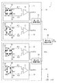
次に、図3を参照して、回転磁界センサ1の構成について詳しく説明する。図3は、回転磁界センサ1の構成を示す回路図である。回転磁界センサ1は、前述のように、第1の検出部10と第2の検出部20とを備えている。第1の検出部10は、第1および第2の検出回路11,12と、第1の演算回路13とを有している。第1および第2の検出回路11,12は、それぞれ第1の印加磁界の一方向の成分の強度を検出して、その強度を表す信号を出力する。第1の演算回路13は、第1および第2の検出回路11,12の出力信号に基づいて第1の角度θ1の検出値である第1の角度検出値θ1sを算出する。
Next, the configuration of the rotating
第2の検出部20の構成は、基本的には、第1の検出部10と同様である。すなわち、第2の検出部20は、第3および第4の検出回路21,22と、第2の演算回路23とを有している。第3および第4の検出回路21,22は、それぞれ第2の印加磁界の一方向の成分の強度を検出して、その強度を表す信号を出力する。第2の演算回路23は、第3および第4の検出回路21,22の出力信号に基づいて第2の角度θ2の検出値である第2の角度検出値θ2sを算出する。
The configuration of the
第1ないし第4の検出回路11,12,21,22の出力信号は、周期が互いに等しい。以下の説明では、第1ないし第4の検出回路11,12,21,22の出力信号の周期を周期Tと記す。第2の検出回路12の出力信号の位相は、第1の検出回路11の出力信号の位相に対して、周期Tの1/4の奇数倍だけ異なっている。第4の検出回路22の出力信号の位相は、第3の検出回路21の出力信号の位相に対して、周期Tの1/4の奇数倍だけ異なっている。
The output signals of the first to
本実施の形態では、第1の部分磁界MF1の方向と第2の部分磁界MF2の方向が互いに180°異なり、第1の方向D1と第2の方向D2も互いに180°異なっていることから、第1の角度検出値θ1sと第2の角度検出値θ2sの位相は等しくなる。 In the present embodiment, the direction of the first partial magnetic field MF1 and the direction of the second partial magnetic field MF2 are different from each other by 180 °, and the first direction D1 and the second direction D2 are also different from each other by 180 °. The first angle detection value θ1s and the second angle detection value θ2s have the same phase.
回転磁界センサ1は、更に、第1の検出部10によって得られた第1の角度検出値θ1sと第2の検出部20によって得られた第2の角度検出値θ2sとに基づいて、基準位置における回転磁界の方向が基準方向に対してなす角度と対応関係を有する検出値θsを算出する第3の演算回路30を備えている。本実施の形態では、第3の演算回路30は、下記の式(1)によって、θsを算出する。
The rotating
θs=(θ1s+θ2s)/2 …(1) θs = (θ1s + θ2s) / 2 (1)
第1ないし第4の検出回路11,12,21,22は、少なくとも1つの磁気検出素子を含んでいる。第1ないし第4の検出回路11,12,21,22は、それぞれ、少なくとも1つの磁気検出素子として、直列に接続された一対の磁気検出素子を含んでいてもよい。この場合、第1ないし第4の検出回路11,12,21,22は、それぞれ、直列に接続された第1の対の磁気検出素子と、直列に接続された第2の対の磁気検出素子とを含むホイートストンブリッジ回路を有していてもよい。以下、第1ないし第4の検出回路11,12,21,22が、それぞれ上記ホイートストンブリッジ回路を有している場合の例について説明する。
The first to
第1の検出回路11は、ホイートストンブリッジ回路14と、差分検出器15とを有している。ホイートストンブリッジ回路14は、電源ポートV1と、グランドポートG1と、2つの出力ポートE11,E12と、直列に接続された第1の対の磁気検出素子R11,R12と、直列に接続された第2の対の磁気検出素子R13,R14とを含んでいる。磁気検出素子R11,R13の各一端は、電源ポートV1に接続されている。磁気検出素子R11の他端は、磁気検出素子R12の一端と出力ポートE11に接続されている。磁気検出素子R13の他端は、磁気検出素子R14の一端と出力ポートE12に接続されている。磁気検出素子R12,R14の各他端は、グランドポートG1に接続されている。電源ポートV1には、所定の大きさの電源電圧が印加される。グランドポートG1はグランドに接続される。差分検出器15は、出力ポートE11,E12の電位差に対応する信号を第1の演算回路13に出力する。
The
第2の検出回路12は、ホイートストンブリッジ回路16と、差分検出器17とを有している。ホイートストンブリッジ回路16は、電源ポートV2と、グランドポートG2と、2つの出力ポートE21,E22と、直列に接続された第1の対の磁気検出素子R21,R22と、直列に接続された第2の対の磁気検出素子R23,R24とを含んでいる。磁気検出素子R21,R23の各一端は、電源ポートV2に接続されている。磁気検出素子R21の他端は、磁気検出素子R22の一端と出力ポートE21に接続されている。磁気検出素子R23の他端は、磁気検出素子R24の一端と出力ポートE22に接続されている。磁気検出素子R22,R24の各他端は、グランドポートG2に接続されている。電源ポートV2には、所定の大きさの電源電圧が印加される。グランドポートG2はグランドに接続される。差分検出器17は、出力ポートE21,E22の電位差に対応する信号を第1の演算回路13に出力する。
The
第3の検出回路21は、ホイートストンブリッジ回路24と、差分検出器25とを有している。ホイートストンブリッジ回路24は、電源ポートV3と、グランドポートG3と、2つの出力ポートE31,E32と、直列に接続された第1の対の磁気検出素子R31,R32と、直列に接続された第2の対の磁気検出素子R33,R34とを含んでいる。磁気検出素子R31,R33の各一端は、電源ポートV3に接続されている。磁気検出素子R31の他端は、磁気検出素子R32の一端と出力ポートE31に接続されている。磁気検出素子R33の他端は、磁気検出素子R34の一端と出力ポートE32に接続されている。磁気検出素子R32,R34の各他端は、グランドポートG3に接続されている。電源ポートV3には、所定の大きさの電源電圧が印加される。グランドポートG3はグランドに接続される。差分検出器25は、出力ポートE31,E32の電位差に対応する信号を第2の演算回路23に出力する。
The
第4の検出回路22は、ホイートストンブリッジ回路26と、差分検出器27とを有している。ホイートストンブリッジ回路26は、電源ポートV4と、グランドポートG4と、2つの出力ポートE41,E42と、直列に接続された第1の対の磁気検出素子R41,R42と、直列に接続された第2の対の磁気検出素子R43,R44とを含んでいる。磁気検出素子R41,R43の各一端は、電源ポートV4に接続されている。磁気検出素子R41の他端は、磁気検出素子R42の一端と出力ポートE41に接続されている。磁気検出素子R43の他端は、磁気検出素子R44の一端と出力ポートE42に接続されている。磁気検出素子R42,R44の各他端は、グランドポートG4に接続されている。電源ポートV4には、所定の大きさの電源電圧が印加される。グランドポートG4はグランドに接続される。差分検出器27は、出力ポートE41,E42の電位差に対応する信号を第2の演算回路23に出力する。
The
本実施の形態では、ホイートストンブリッジ回路(以下、ブリッジ回路と記す。)14,16,24,26に含まれる全ての磁気検出素子として、MR素子、特にTMR素子を用いている。なお、TMR素子の代りにGMR素子を用いてもよい。TMR素子またはGMR素子は、磁化方向が固定された磁化固定層と、印加される磁界の方向に応じて磁化の方向が変化する自由層と、磁化固定層と自由層の間に配置された非磁性層とを有している。TMR素子では、非磁性層はトンネルバリア層である。GMR素子では、非磁性層は非磁性導電層である。TMR素子またはGMR素子では、自由層の磁化の方向が磁化固定層の磁化の方向に対してなす角度に応じて抵抗値が変化し、この角度が0°のときに抵抗値は最小値となり、角度が180°のときに抵抗値は最大値となる。以下の説明では、ブリッジ回路14,16,24,26に含まれる磁気検出素子をMR素子と記す。図3において、塗りつぶした矢印は、MR素子における磁化固定層の磁化の方向を表し、白抜きの矢印は、MR素子における自由層の磁化の方向を表している。
In the present embodiment, MR elements, particularly TMR elements, are used as all magnetic detection elements included in the Wheatstone bridge circuit (hereinafter referred to as bridge circuit) 14, 16, 24, and 26. A GMR element may be used in place of the TMR element. The TMR element or the GMR element includes a magnetization fixed layer whose magnetization direction is fixed, a free layer whose magnetization direction changes according to the direction of an applied magnetic field, and a non-magnetic layer disposed between the magnetization fixed layer and the free layer. And a magnetic layer. In the TMR element, the nonmagnetic layer is a tunnel barrier layer. In the GMR element, the nonmagnetic layer is a nonmagnetic conductive layer. In the TMR element or the GMR element, the resistance value changes according to the angle formed by the magnetization direction of the free layer with respect to the magnetization direction of the magnetization fixed layer, and when this angle is 0 °, the resistance value becomes the minimum value. When the angle is 180 °, the resistance value becomes the maximum value. In the following description, the magnetic detection elements included in the
第1の検出回路11では、MR素子R11,R14における磁化固定層の磁化の方向はX方向であり、MR素子R12,R13における磁化固定層の磁化の方向は−X方向である。この場合、第1の印加磁界のX方向の成分の強度に応じて、出力ポートE11,E12の電位差が変化する。従って、第1の検出回路11は、第1の印加磁界のX方向の成分の強度を検出して、その強度を表す信号を出力する。図4(a)に示した第1の角度θ1が0°のときと180°のときは、第1の印加磁界のX方向の成分の強度は0である。第1の角度θ1が0°よりも大きく180゜よりも小さいときは、第1の印加磁界のX方向の成分の強度は正の値である。第1の角度θ1が180°よりも大きく360゜よりも小さいときは、第1の印加磁界のX方向の成分の強度は負の値である。
In the
第2の検出回路12では、MR素子R21,R24における磁化固定層の磁化の方向はY方向であり、MR素子R22,R23における磁化固定層の磁化の方向は−Y方向である。この場合、第1の印加磁界のY方向の成分の強度に応じて、出力ポートE21,E22の電位差が変化する。従って、第2の検出回路12は、第1の印加磁界のY方向の成分の強度を検出して、その強度を表す信号を出力する。図4(a)に示した第1の角度θ1が90°のときと270°のときは、第1の印加磁界のY方向の成分の強度は0である。第1の角度θ1が0°以上90゜未満のとき、および270°より大きく360°以下のときは、第1の印加磁界のY方向の成分の強度は正の値である。第1の角度θ1が90°よりも大きく270゜よりも小さいときは、第1の印加磁界のY方向の成分の強度は負の値である。
In the
図3に示した例では、第2の検出回路12におけるMR素子の磁化固定層の磁化方向は、第1の検出回路11におけるMR素子の磁化固定層の磁化方向に直交している。理想的には、第1の検出回路11の出力信号の波形はサイン(Sine)波形になり、第2の検出回路12の出力信号の波形はコサイン(Cosine)波形になる。この場合、第2の検出回路12の出力信号の位相は、第1の検出回路11の出力信号の位相に対して、周期Tの1/4だけ異なっている。ここで、第1の検出回路11の出力信号をsinθ1sと表し、第2の検出回路12の出力信号をcosθ1sと表すと、第1の角度検出値θ1sは、下記の式(2)によって算出することができる。なお、“atan”は、アークタンジェントを表す。
In the example shown in FIG. 3, the magnetization direction of the magnetization fixed layer of the MR element in the
θ1s=atan(sinθ1s/cosθ1s) …(2) θ1s = atan (sin θ1s / cos θ1s) (2)
なお、360°の範囲内で、式(2)におけるθ1sの解には、180°異なる2つの値がある。しかし、sinθ1sとcosθ1sの正負の組み合わせにより、θ1sの真の値が、式(2)におけるθ1sの2つの解のいずれであるかを判別することができる。すなわち、sinθ1sが正の値のときは、θ1sは0°よりも大きく180゜よりも小さい。sinθ1sが負の値のときは、θ1sは180°よりも大きく360゜よりも小さい。cosθ1sが正の値のときは、θ1sは、0°以上90゜未満、および270°より大きく360°以下の範囲内である。cosθ1sが負の値のときは、θ1sは、90°よりも大きく270゜よりも小さい。第1の演算回路13は、式(2)と、上記のsinθ1sとcosθ1sの正負の組み合わせの判定により、360°の範囲内でθ1sを求める。なお、第2の検出回路12の出力信号の位相が、第1の検出回路11の出力信号の位相に対して、周期Tの1/4だけ異なる場合に限らず、第2の検出回路12の出力信号の位相が、第1の検出回路11の出力信号の位相に対して、周期Tの1/4の奇数倍だけ異なっていれば、θ1sを求めることができる。
Within the range of 360 °, the solution of θ1s in equation (2) has two values that differ by 180 °. However, it is possible to determine which of the two solutions of θ1s in Equation (2) is the true value of θ1s by the combination of the sign of sin θ1s and cos θ1s. That is, when sin θ1s is a positive value, θ1s is larger than 0 ° and smaller than 180 °. When sin θ1s is a negative value, θ1s is greater than 180 ° and smaller than 360 °. When cos θ1s is a positive value, θ1s is in the range of 0 ° to less than 90 ° and greater than 270 ° to 360 °. When cos θ1s is a negative value, θ1s is greater than 90 ° and smaller than 270 °. The first
第3の検出回路21では、MR素子R31,R34における磁化固定層の磁化の方向は−X方向であり、MR素子R32,R33における磁化固定層の磁化の方向はX方向である。この場合、第2の印加磁界の−X方向の成分の強度に応じて、出力ポートE31,E32の電位差が変化する。従って、第3の検出回路21は、第2の印加磁界の−X方向の成分の強度を検出して、その強度を表す信号を出力する。図4(b)に示した第2の角度θ2が0°のときと180°のときは、第2の印加磁界の−X方向の成分の強度は0である。第2の角度θ2が0°よりも大きく180゜よりも小さいときは、第2の印加磁界の−X方向の成分の強度は正の値である。第2の角度θ2が180°よりも大きく360゜よりも小さいときは、第2の印加磁界の−X方向の成分の強度は負の値である。
In the
第4の検出回路22では、MR素子R41,R44における磁化固定層の磁化の方向は−Y方向であり、MR素子R42,R43における磁化固定層の磁化の方向はY方向である。この場合、第2の印加磁界の−Y方向の成分の強度に応じて、出力ポートE41,E42の電位差が変化する。従って、第4の検出回路22は、第2の印加磁界の−Y方向の成分の強度を検出して、その強度を表す信号を出力する。図4(b)に示した第2の角度θ2が90°のときと270°のときは、第2の印加磁界の−Y方向の成分の強度は0である。第2の角度θ2が0°以上90゜未満のとき、および270°より大きく360°以下のときは、第2の印加磁界の−Y方向の成分の強度は正の値である。第2の角度θ2が90°よりも大きく270゜よりも小さいときは、第2の印加磁界の−Y方向の成分の強度は負の値である。
In the
図3に示した例では、第4の検出回路22におけるMR素子の磁化固定層の磁化方向は、第3の検出回路21におけるMR素子の磁化固定層の磁化方向に直交している。理想的には、第3の検出回路21の出力信号の波形はサイン(Sine)波形になり、第4の検出回路22の出力信号の波形はコサイン(Cosine)波形になる。この場合、第4の検出回路22の出力信号の位相は、第3の検出回路21の出力信号の位相に対して、周期Tの1/4だけ異なっている。ここで、第3の検出回路21の出力信号をsinθ2sと表し、第4の検出回路22の出力信号をcosθ2sと表すと、第2の角度検出値θ2sは、下記の式(3)によって算出することができる。
In the example shown in FIG. 3, the magnetization direction of the magnetization fixed layer of the MR element in the
θ2s=atan(sinθ2s/cosθ2s) …(3) θ2s = atan (sin θ2s / cos θ2s) (3)
第2の演算回路23は、前述のθ1sの求め方と同様に、式(3)と、sinθ2sとcosθ2sの正負の組み合わせの判定により、360°の範囲内でθ2sを求める。なお、第4の検出回路22の出力信号の位相が、第3の検出回路21の出力信号の位相に対して、周期Tの1/4だけ異なる場合に限らず、第4の検出回路22の出力信号の位相が、第3の検出回路21の出力信号の位相に対して、周期Tの1/4の奇数倍だけ異なっていれば、θ2sを求めることができる。
The second
第1ないし第3の演算回路13,23,30は、例えば、1つのマイクロコンピュータによって実現することができる。
The first to third
次に、図6を参照して、MR素子の構成の一例について説明する。図6は、図3に示した回転磁界センサ1における1つのMR素子の一部を示す斜視図である。この例では、1つのMR素子は、複数の下部電極と、複数のMR膜と、複数の上部電極とを有している。複数の下部電極42は図示しない基板上に配置されている。個々の下部電極42は細長い形状を有している。下部電極42の長手方向に隣接する2つの下部電極42の間には、間隙が形成されている。図6に示したように、下部電極42の上面上において、長手方向の両端の近傍に、それぞれMR膜50が配置されている。MR膜50は、下部電極42側から順に積層された自由層51、非磁性層52、磁化固定層53および反強磁性層54を含んでいる。自由層51は、下部電極42に電気的に接続されている。反強磁性層54は、反強磁性材料よりなり、磁化固定層53との間で交換結合を生じさせて、磁化固定層53の磁化の方向を固定する。複数の上部電極43は、複数のMR膜50の上に配置されている。個々の上部電極43は細長い形状を有し、下部電極42の長手方向に隣接する2つの下部電極42上に配置されて隣接する2つのMR膜50の反強磁性層54同士を電気的に接続する。このような構成により、図6に示したMR素子は、複数の下部電極42と複数の上部電極43とによって直列に接続された複数のMR膜50を有している。なお、MR膜50における層51〜54の配置は、図6に示した配置とは上下が反対でもよい。
Next, an example of the configuration of the MR element will be described with reference to FIG. FIG. 6 is a perspective view showing a part of one MR element in the
次に、図3ないし図5を参照して、回転磁界センサ1の作用および効果について説明する。回転磁界センサ1では、第1の検出部10によって、第1および第2の検出回路11,12の出力信号に基づいて第1の角度θ1の検出値である第1の角度検出値θ1sを求める。また、第2の検出部20によって、第3および第4の検出回路21,22の出力信号に基づいて第2の角度θ2の検出値である第2の角度検出値θ2sを求める。そして、第1の角度検出値θ1sと第2の角度検出値θ2sとに基づいて、第3の演算回路30によって、基準位置における回転磁界の方向が基準方向に対してなす角度と対応関係を有する検出値θsを算出する。
Next, operations and effects of the rotating
本実施の形態によれば、回転磁界センサ1に対して外部から、回転磁界以外のノイズ磁界が印加された場合であっても、ノイズ磁界に起因した検出値θsの誤差を低減することが可能になる。以下、これについて詳しく説明する。なお、以下の説明では、上記のノイズ磁界をノイズ磁界Hextと記す。図4において記号Hextを付した矢印は、ノイズ磁界Hextの一例を示している。
According to the present embodiment, even when a noise magnetic field other than the rotating magnetic field is applied to the rotating
まず、図5を参照して、第1および第2の印加磁界とノイズ磁界Hextとの関係について説明する。図5は、第1および第2の印加磁界とノイズ磁界Hextとの関係を模式的に示す説明図である。ノイズ磁界Hextがない場合には、第1の印加磁界の成分は第1の部分磁界MF1のみであり、第2の印加磁界の成分は第2の部分磁界MF2のみである。図5において、記号AMF1aを付した矢印は、この場合における第1の印加磁界を表し、記号AMF2aを付した矢印は、この場合における第2の印加磁界を表している。図5に示したように、第1の印加磁界AMF1aの方向と第2の印加磁界AMF2aの方向は、第1の部分磁界MF1の方向と第2の部分磁界MF2の方向と同様に、互いに180°異なっている。 First, the relationship between the first and second applied magnetic fields and the noise magnetic field H ext will be described with reference to FIG. FIG. 5 is an explanatory diagram schematically showing the relationship between the first and second applied magnetic fields and the noise magnetic field H ext . In the absence of the noise magnetic field H ext , the first applied magnetic field component is only the first partial magnetic field MF1, and the second applied magnetic field component is only the second partial magnetic field MF2. In FIG. 5, the arrow with the symbol AMF1a represents the first applied magnetic field in this case, and the arrow with the symbol AMF2a represents the second applied magnetic field in this case. As shown in FIG. 5, the direction of the first applied magnetic field AMF1a and the direction of the second applied magnetic field AMF2a are 180 with respect to each other in the same manner as the direction of the first partial magnetic field MF1 and the direction of the second partial magnetic field MF2. ° Different.
ノイズ磁界Hextが印加された場合には、第1の印加磁界は、第1の部分磁界MF1とノイズ磁界Hextとの合成磁界となり、第2の印加磁界は、第2の部分磁界MF2とノイズ磁界Hextとの合成磁界となる。図5において、記号AMF1bを付した矢印は、この場合における第1の印加磁界を表し、記号AMF2bを付した矢印は、この場合における第2の印加磁界を表している。 When the noise magnetic field H ext is applied, the first applied magnetic field is a combined magnetic field of the first partial magnetic field MF1 and the noise magnetic field H ext, and the second applied magnetic field is the second partial magnetic field MF2. It becomes a combined magnetic field with the noise magnetic field H ext . In FIG. 5, the arrow with the symbol AMF1b represents the first applied magnetic field in this case, and the arrow with the symbol AMF2b represents the second applied magnetic field in this case.
次に、第1および第2の角度検出値θ1s,θ2sとノイズ磁界Hextとの関係について説明する。ノイズ磁界Hextがない場合には、第1の角度検出値θ1sは、第1の印加磁界AMF1a、すなわち第1の部分磁界MF1の方向が第1の方向D1に対してなす角度θ1mと等しくなる。ノイズ磁界Hextが印加された場合には、第1の角度検出値θ1sは、第1の印加磁界AMF1b、すなわち第1の部分磁界MF1とノイズ磁界Hextとの合成磁界が第1の方向D1に対してなす角度と等しくなる。この合成磁界が第1の方向D1に対してなす角度と角度θ1mとの差は、ノイズ磁界Hextに起因して生じるものであり、角度検出値θ1sの誤差となるものである。本実施の形態では、この誤差を第1のノイズ誤差と呼び、記号dθ1nで表す。図5には、dθ1nも示している。 Next, the relationship between the first and second detected angle values θ1s and θ2s and the noise magnetic field H ext will be described. In the absence of the noise magnetic field H ext , the first detected angle value θ1s is equal to the first applied magnetic field AMF1a, that is, the angle θ1m that the direction of the first partial magnetic field MF1 forms with respect to the first direction D1. . When the noise magnetic field H ext is applied, the first angle detection value θ1s is determined by the first applied magnetic field AMF1b, that is, the combined magnetic field of the first partial magnetic field MF1 and the noise magnetic field H ext in the first direction D1. Is equal to the angle formed with respect to. The difference between the angle formed by the combined magnetic field with respect to the first direction D1 and the angle θ1m is caused by the noise magnetic field H ext and is an error of the detected angle value θ1s. In the present embodiment, this error is referred to as a first noise error and is represented by the symbol dθ1n. FIG. 5 also shows dθ1n.
同様に、ノイズ磁界Hextがない場合には、第2の角度検出値θ2sは、第2の印加磁界AMF2a、すなわち第2の部分磁界MF2の方向が第2の方向D2に対してなす角度θ2mと等しくなる。ノイズ磁界Hextが印加された場合には、第2の角度検出値θ2sは、第2の印加磁界AMF2b、すなわち第2の部分磁界MF2とノイズ磁界Hextとの合成磁界が第2の方向D2に対してなす角度と等しくなる。この合成磁界が第2の方向D2に対してなす角度と角度θ2mとの差は、ノイズ磁界Hextに起因して生じるものであり、角度検出値θ2sの誤差となるものである。本実施の形態では、この誤差を第2のノイズ誤差と呼び、記号dθ2nで表す。図5には、dθ2nも示している。 Similarly, when there is no noise magnetic field H ext , the second detected angle value θ2s is an angle θ2m formed by the second applied magnetic field AMF2a, that is, the direction of the second partial magnetic field MF2 with respect to the second direction D2. Is equal to When the noise magnetic field H ext is applied, the second detected angle value θ2s is the second applied magnetic field AMF2b, that is, the combined magnetic field of the second partial magnetic field MF2 and the noise magnetic field H ext in the second direction D2. Is equal to the angle formed with respect to. The difference between the angle formed by the combined magnetic field with respect to the second direction D2 and the angle θ2m is caused by the noise magnetic field H ext and causes an error in the detected angle value θ2s. In the present embodiment, this error is called a second noise error and is represented by the symbol dθ2n. FIG. 5 also shows dθ2n.
なお、第1のノイズ誤差dθ1nは、第1の部分磁界MF1から時計回り方向に見たときに正の値で表し、第1の部分磁界MF1から反時計回り方向に見たときに負の値で表すものとする。また、第2のノイズ誤差dθ2nは、第1のノイズ誤差dθ1nと同様に、第2の部分磁界MF2から時計回り方向に見たときに正の値で表し、第2の部分磁界MF2から反時計回り方向に見たときに負の値で表すものとする。 The first noise error dθ1n is expressed as a positive value when viewed in the clockwise direction from the first partial magnetic field MF1, and is a negative value when viewed in the counterclockwise direction from the first partial magnetic field MF1. It shall be expressed as Similarly to the first noise error dθ1n, the second noise error dθ2n is represented by a positive value when viewed in the clockwise direction from the second partial magnetic field MF2, and counterclockwise from the second partial magnetic field MF2. When viewed in the direction of rotation, it shall be expressed as a negative value.
図5に示した例では、第1の印加磁界AMF1bの方向は、第1の部分磁界MF1の方向に対して、図5における反時計回り方向に第1のノイズ誤差dθ1nの絶対値|dθ1n|だけ異なっている。また、第2の印加磁界AMF2bの方向は、第2の部分磁界MF2の方向に対して、図5における時計回り方向に第2のノイズ誤差dθ2nの絶対値|dθ2n|だけ異なっている。この場合、第1の角度検出値θ1sと第2の角度検出値θ2sは、それぞれ下記の式(4),(5)で表される。 In the example shown in FIG. 5, the absolute value of the first noise error dθ1n | dθ1n | in the direction of the first applied magnetic field AMF1b is counterclockwise in FIG. 5 with respect to the direction of the first partial magnetic field MF1. Only different. Further, the direction of the second applied magnetic field AMF2b differs from the direction of the second partial magnetic field MF2 by the absolute value | dθ2n | of the second noise error dθ2n in the clockwise direction in FIG. In this case, the first angle detection value θ1s and the second angle detection value θ2s are expressed by the following equations (4) and (5), respectively.
θ1s=θ1m−|dθ1n| …(4)
θ2s=θ2m+|dθ2n| …(5)
θ1s = θ1m− | dθ1n | (4)
θ2s = θ2m + | dθ2n | (5)
次に、検出値θsとノイズ磁界Hextとの関係について説明する。前述のように、第3の演算回路30は、第1の角度検出値θ1sと第2の角度検出値θ2sとに基づいて、式(1)によって、検出値θsを算出する。式(1)に、式(4),(5)を代入すると、下記の式(6)が得られる。
Next, the relationship between the detected value θs and the noise magnetic field H ext will be described. As described above, the third
θs=(θ1s+θ2s)/2
=(θ1m−|dθ1n|+θ2m+|dθ2n|)/2
=(θ1m+θ2m)/2+(−|dθ1n|+|dθ2n|)/2 …(6)
θs = (θ1s + θ2s) / 2
= (Θ1m− | dθ1n | + θ2m + | dθ2n |) / 2
= (Θ1m + θ2m) / 2 + (− | dθ1n | + | dθ2n |) / 2 (6)
前述のように、角度θ1mと角度θ2mは等しくなる。ここで、回転磁界センサ1によって検出される、基準位置における回転磁界の方向が基準方向に対してなす角度を角度θと記す。角度θが角度θ1mと等しいと仮定すると、ノイズ磁界Hextが印加されない場合には、検出値θsは、理想的には、角度θと等しくなる。しかし、式(6)から理解されるように、検出値θsは、第1のノイズ誤差dθ1nと第2のノイズ誤差dθ2nの両方と対応関係を有する誤差を含んでいる。この誤差は、ノイズ磁界Hextに起因して生じるものである。
As described above, the angle θ1m and the angle θ2m are equal. Here, the angle formed by the rotating
次に、本実施の形態によれば、ノイズ磁界Hextに起因した検出値θsの誤差を低減することが可能になる理由について説明する。図5に示した例では、第1のノイズ誤差dθ1nは負の値(−|dθ1n|)になり、第2のノイズ誤差dθ2nは正の値(|dθ2n|)になる。従って、式(6)によって検出値θsを算出する際に、第1のノイズ誤差dθ1nの値と第2のノイズ誤差dθ2nの値が相殺されて検出値θsの誤差の絶対値は、第1のノイズ誤差dθ1nの絶対値と第2のノイズ誤差dθ2nの絶対値のいずれよりも小さくなる。 Next, the reason why it becomes possible to reduce the error of the detected value θs caused by the noise magnetic field H ext according to the present embodiment will be described. In the example shown in FIG. 5, the first noise error dθ1n has a negative value (− | dθ1n |), and the second noise error dθ2n has a positive value (| dθ2n |). Therefore, when the detection value θs is calculated by the equation (6), the value of the first noise error dθ1n and the value of the second noise error dθ2n are canceled, and the absolute value of the error of the detection value θs is the first value. It becomes smaller than both the absolute value of the noise error dθ1n and the absolute value of the second noise error dθ2n.
なお、ノイズ磁界Hextの方向が図5に示した例とは反対方向である場合には、第1の印加磁界AMF1bの方向は、第1の部分磁界MF1の方向に対して、図5における時計回り方向に第1のノイズ誤差dθ1nの絶対値|dθ1n|だけ異なり、第2の印加磁界AMF2bの方向は、第2の部分磁界MF2の方向に対して、図5における反時計回り方向に第2のノイズ誤差dθ2nの絶対値|dθ2n|だけ異なる。すなわち、この場合には、第1のノイズ誤差dθ1nは正の値(|dθ1n|)になり、第2のノイズ誤差dθ2nは負の値(−|dθ2n|)になる。この場合にも、検出値θsを算出する際に、第1のノイズ誤差dθ1nの値と第2のノイズ誤差dθ2nの値が相殺されて検出値θsの誤差の絶対値は、第1のノイズ誤差dθ1nの絶対値と第2のノイズ誤差dθ2nの絶対値のいずれよりも小さくなる。 When the direction of the noise magnetic field H ext is the opposite direction to the example shown in FIG. 5, the direction of the first applied magnetic field AMF1b is the same as the direction of the first partial magnetic field MF1 in FIG. In the clockwise direction, the absolute value of the first noise error dθ1n differs from | dθ1n |, and the direction of the second applied magnetic field AMF2b is the second counterclockwise direction in FIG. 5 with respect to the direction of the second partial magnetic field MF2. 2 is different by an absolute value | dθ2n | of the noise error dθ2n. That is, in this case, the first noise error dθ1n is a positive value (| dθ1n |), and the second noise error dθ2n is a negative value (− | dθ2n |). Also in this case, when calculating the detection value θs, the value of the first noise error dθ1n and the value of the second noise error dθ2n are canceled out, and the absolute value of the error of the detection value θs is the first noise error. It becomes smaller than both the absolute value of dθ1n and the absolute value of the second noise error dθ2n.
もし、回転磁界センサが、第1の検出部10と第2の検出部20の一方のみを備え、第1の角度検出値θ1sと第2の角度検出値θ2sの一方を検出値θsとする場合には、検出値θsに含まれる誤差は、第1のノイズ誤差dθ1nまたは第2のノイズ誤差dθ2nとなる。これに対し、本実施の形態に係る回転磁界センサは、第1の検出部10と第2の検出部20を備え、式(6)によって検出値θsを算出する。本実施の形態では、上記の例に限らず、第1のノイズ誤差dθ1nと第2のノイズ誤差dθ2nが共に0になる場合を除いて、第1のノイズ誤差dθ1nと第2のノイズ誤差dθ2nは、正負の符号が反対の値になる。そのため、上述のように、第3の演算回路30によって検出値θsを算出する際に、検出値θsに含まれる誤差の絶対値は、第1のノイズ誤差dθ1nの絶対値と第2のノイズ誤差dθ2nの絶対値のいずれよりも小さくなる。これにより、本実施の形態によれば、ノイズ磁界Hextに起因した検出角度の誤差を低減することが可能になる。
If the rotating magnetic field sensor includes only one of the
また、本実施の形態では、第1および第2の検出回路11,12を有する第1の検出部10は第1の位置に配置され、第3および第4の検出回路21,22を有する第2の検出部20は第2の位置に配置されている。そのため、本実施の形態によれば、第1ないし第4の検出回路11,12,21,22を互いに異なる場所に設置する場合に比べて、第1ないし第4の検出回路11,12,21,22の設置箇所を少なくすることができる。また、第1ないし第4の検出回路11,12,21,22は、それぞれ、少なくとも1つのMR素子を含んでいる。本実施の形態によれば、上述のように、第1ないし第4の検出回路11,12,21,22の設置箇所を少なくすることができるので、検出回路11,12,21,22に含まれるMR素子の設置箇所を少なくすることができる。以上のことから、本実施の形態によれば、磁気検出素子(MR素子)の設置箇所を少なくしながら、ノイズ磁界Hextに起因した検出角度の誤差を低減することが可能になる。
Further, in the present embodiment, the
[変形例]
以下、本実施の形態における第1および第2の変形例について説明する。始めに、図7を参照して、本実施の形態における第1の変形例の回転磁界センサ1について説明する。図7は、第1の変形例の回転磁界センサ1の概略の構成を示す側面図である。第1の変形例では、一対の磁石3,4は、円板部5の上面から離れるに従って互いの距離が大きくなるように、回転中心Cに対して傾いている。磁石3のN極とS極は、回転中心Cに対して傾き、且つ円板部5の上面から離れる方向に、S極、N極の順に配置されている。磁石4のN極とS極は、回転中心Cに対して傾き、且つ円板部5の上面から離れる方向に、N極、S極の順に配置されている。
[Modification]
Hereinafter, first and second modifications of the present embodiment will be described. First, with reference to FIG. 7, the
図7では、磁石3のN極から磁石4のS極に向かう磁束の主要部分と、磁石4のN極から磁石3のS極に向かう磁束の主要部分を、記号Mを付した曲線または直線で表している。これらの磁束の主要部分は、一対の磁石3,4が回転中心Cに対して傾いていない場合(図2)に比べて、図7における上方に変位している。図2に示したように、一対の磁石3,4が回転中心Cに対して傾いていない場合には、磁石4のN極から磁石3のS極に向かう磁束の主要部分が、円板部5の上面よりも下方を通過する可能性がある。この場合には、第2の検出部20を最適な位置、すなわち磁石4のN極から磁石3のS極に向かう磁束の主要部分が通過する位置に設置することが困難になる場合がある。これに対し、第1の変形例によれば、磁石4のN極から磁石3のS極に向かう磁束の主要部分が、円板部5の上面よりも上方を通過するように、磁束の分布を調整することが可能になる。これにより、容易に、第2の検出部20を最適な位置に設置することが可能になる。
In FIG. 7, the main part of the magnetic flux from the N pole of the
次に、図8を参照して、本実施の形態における第2の変形例の回転磁界センサ1について説明する。図8は、第2の変形例の回転磁界センサ1の概略の構成を示す側面図である。第2の変形例では、一対の磁石3,4は、円板部5の上面から離れた位置に配置されている。磁界発生部2は、図1および図2に示した本実施の形態における磁界発生部2の構成要素に加えて、円板部5の上面に固定された支持部7,8を有している。磁石3,4は、それぞれ支持部7,8の上に固定されている。
Next, with reference to FIG. 8, the
図8では、回転磁界のうち、磁石3のN極から磁石4のS極に向かう磁束の主要部分と、磁石4のN極から磁石3のS極に向かう磁束の主要部分を、記号Mを付した曲線で表している。これらの磁束の主要部分は、磁石3,4が円板部5の上面に固定されている場合(図2)に比べて、図8における上方に変位している。これにより、第2の変形例によれば、第1の変形例と同様に、容易に、第2の検出部20を最適な位置に設置することが可能になる。
In FIG. 8, the main part of the magnetic flux from the N pole of the
[第2の実施の形態]
次に、図9および図10を参照して、本発明の第2の実施の形態に係る回転磁界センサについて説明する。図9は、本実施の形態に係る回転磁界センサの概略の構成を示す斜視図である。図10は、本実施の形態に係る回転磁界センサの概略の構成を示す側面図である。図9および図10に示したように、本実施の形態に係る回転磁界センサ61は、第1の実施の形態における磁界発生部2の代りに、磁界発生部62を備えている。
[Second Embodiment]
Next, a rotating field sensor according to the second embodiment of the present invention will be described with reference to FIGS. 9 and 10. FIG. 9 is a perspective view showing a schematic configuration of the rotating field sensor according to the present embodiment. FIG. 10 is a side view showing a schematic configuration of the rotating field sensor according to the present embodiment. As shown in FIGS. 9 and 10, the rotating
磁界発生部62は、回転位置を検出する対象物である回転軸66に取り付けられたリング状の磁石63を有している。図9および図10において、記号Cを付した一点鎖線は、回転軸66の中心軸を含む回転中心を示している。磁石63は、回転中心Cを中心として対称に配置されるように、図示しない固定手段によって回転軸66に固定されている。磁石63は、回転軸66に連動して、回転中心Cを中心として回転する。これにより、磁石63が発生する磁界に基づいて、回転磁界が発生される。
The
磁石63は、それぞれ、1組以上のN極とS極が交互にリング状に配列された第1層63Aおよび第2層63Bを有している。第1層63Aおよび第2層63Bは、図9および図10における上下方向(回転中心Cに平行な方向)に積層されている。第1層63AのN極と第2層63BのS極は、上下に隣接するように配置されている。第1層63AのS極と第2層63BのN極も、上下に隣接するように配置されている。
Each of the
図9および図10に示したように、第1および第2の検出部10,20は、磁石63の外周部の外側の位置において、回転中心Cに平行な方向に並ぶように配置されている。第1の検出部10が配置された位置が第1の位置であり、第2の検出部20が配置された位置が第2の位置である。第1の位置は、第1層63Aと第2層63Bの界面を含む仮想の平面よりも上方にある。第2の位置は、上記仮想の平面よりも下方にある。回転磁界は、第1の位置における第1の部分磁界MF1と第2の位置における第2の部分磁界MF2とを含んでいる。主に第1層63Aの近傍における磁束が第1の部分磁界MF1を発生させる。第1層63Aの近傍における磁束には、上下に隣接する第1層63Aと第2層63Bにおける異なる2つの極の間の磁束と、第1層63Aにおいて回転方向に隣接する異なる2つの極の間の磁束とが含まれる。また、主に第2層63Bの近傍における磁束が第2の部分磁界MF2を発生させる。第2層63Bの近傍における磁束には、上下に隣接する第1層63Aと第2層63Bにおける異なる2つの極の間の磁束と、第2層63Bにおいて回転方向に隣接する異なる2つの極の間の磁束とが含まれる。図10では、第1層63AのN極から第2層63BのS極に向かう磁束の主要部分を、記号Mを付した曲線で表している。第1の部分磁界MF1と第2の部分磁界MF2は、磁界の方向が互いに180°異なり且つ同じ回転方向に回転する。
As shown in FIGS. 9 and 10, the first and
第1の検出部10は、第1の位置において、主成分として第1の部分磁界MF1を含む第1の印加磁界の方向が第1の方向D1に対してなす第1の角度を検出する。第2の検出部20は、第2の位置において、主成分として第2の部分磁界MF2を含む第2の印加磁界の方向が第2の方向D2に対してなす第2の角度を検出する。第1の方向D1と第2の方向D2は、互いに180°異なっている。第1の方向D1は、例えば、回転中心Cから第1の検出部10に向かう方向である。
The
図9に示した例では、第1層63Aおよび第2層63Bは、それぞれ、5組のN極とS極とを含み、磁石63が1回転する間に、第1の部分磁界MF1と第2の部分磁界MF2は5回転する。この場合、検出回路11,12,21,22の出力信号における1周期すなわち電気角の360°は、磁石63の1/5回転すなわち磁石63の回転角の72°に相当する。
In the example shown in FIG. 9, each of the
[変形例]
次に、図11を参照して、本実施の形態における変形例について説明する。図11は、本実施の形態における変形例の回転磁界センサ61の概略の構成を示す側面図である。図11に示したように、変形例の回転磁界センサ61は、磁界発生部62の代りに、磁界発生部72を備えている。
[Modification]
Next, a modification of the present embodiment will be described with reference to FIG. FIG. 11 is a side view showing a schematic configuration of a
磁界発生部72は、一方向に長い磁石73を有している。磁石73は、対象物の直線的な運動に連動して、その長手方向に直線的に移動する。これにより、磁石73が発生する磁界に基づいて、回転磁界が発生される。磁石73は、それぞれ、複数組のN極とS極が交互に直線状に配列された第1層73Aおよび第2層73Bを有している。第1層73Aおよび第2層73Bは、図11における上下方向(磁石73の移動方向に直交する方向)に積層されている。第1層73AのN極と第2層73BのS極は、上下に隣接するように配置されている。第1層73AのS極と第2層73BのN極も、上下に隣接するように配置されている。
The
図11に示したように、第1および第2の検出部10,20は、磁石73の側方において、図11における上下方向(第1層73Aと第2層73Bの積層方向)に並ぶように配置されている。第1の検出部10が配置された位置が第1の位置であり、第2の検出部20が配置された位置が第2の位置である。第1の位置は、第1層73Aと第2層73Bの界面を含む仮想の平面よりも上方にある。第2の位置は、上記仮想の平面よりも下方にある。回転磁界は、第1の位置における第1の部分磁界MF1と第2の位置における第2の部分磁界MF2とを含んでいる。主に第1層73Aの近傍における磁束が第1の部分磁界MF1を発生させる。第1層73Aの近傍における磁束には、上下に隣接する第1層73Aと第2層73Bにおける異なる2つの極の間の磁束と、第1層73Aにおいて磁石73の移動方向に隣接する異なる2つの極の間の磁束とが含まれる。また、主に第2層73Bの近傍における磁束が第2の部分磁界MF2を発生させる。第2層73Bの近傍における磁束には、上下に隣接する第1層73Aと第2層73Bにおける異なる2つの極の間の磁束と、第2層73Bにおいて磁石73の移動方向に隣接する異なる2つの極の間の磁束とが含まれる。第1の部分磁界MF1と第2の部分磁界MF2は、磁界の方向が互いに180°異なり且つ同じ回転方向に回転する。
As shown in FIG. 11, the first and
第1の検出部10は、第1の位置において、主成分として第1の部分磁界MF1を含む第1の印加磁界の方向が第1の方向D1に対してなす第1の角度を検出する。第2の検出部20は、第2の位置において、主成分として第2の部分磁界MF2を含む第2の印加磁界の方向が第2の方向D2に対してなす第2の角度を検出する。第1の方向D1と第2の方向D2は、互いに180°異なっている。第1の方向D1は、例えば、第1の検出部10に向いた磁石73の側面に垂直であって、磁石73から第1の検出部10に向かう方向である。
The
磁石73が、1ピッチ分すなわちN極とS極の1組分だけ移動すると、第1の部分磁界MF1と第2の部分磁界MF2がそれぞれ1回転する。この場合、検出回路11,12,21,22の出力信号における1周期すなわち電気角の360°は、磁石73の1ピッチに相当する。
When the
本実施の形態におけるその他の構成、作用および効果は、第1の実施の形態と同様である。 Other configurations, operations, and effects in the present embodiment are the same as those in the first embodiment.
[第3の実施の形態]
次に、図12を参照して、本発明の第3の実施の形態に係る回転磁界センサについて説明する。図12は、本実施の形態に係る回転磁界センサの概略の構成を示す斜視図である。図12に示したように、本実施の形態に係る回転磁界センサ81は、第2の実施の形態における磁界発生部62の代りに、磁界発生部82を備えている。
[Third Embodiment]
Next, with reference to FIG. 12, a rotating magnetic field sensor according to a third embodiment of the invention will be described. FIG. 12 is a perspective view showing a schematic configuration of the rotating field sensor according to the present embodiment. As shown in FIG. 12, the rotating
磁界発生部82は、回転位置を検出する対象物である回転軸66に取り付けられたリング状の磁石83を有している。図12において、記号Cを付した一点鎖線は、回転軸66の中心軸を含む回転中心を示している。磁石83は、回転中心Cを中心として対称に配置されるように、図示しない固定手段によって回転軸66に固定されている。磁石83は、回転軸66に連動して、回転中心Cを中心として回転する。これにより、磁石83が発生する磁界に基づいて、回転磁界が発生される。磁石83は、2n組(nは1以上の整数)のN極とS極が交互にリング状に配列されて構成されている。図12に示した例では、磁石83は、2組のN極とS極を含んでいる。
The
図12に示したように、第1および第2の検出部10,20は、磁石83を挟むように、回転中心Cを含む仮想の平面に対して対称な位置に配置されている。第1の検出部10が配置された位置が第1の位置であり、第2の検出部20が配置された位置が第2の位置である。回転磁界は、第1の位置における第1の部分磁界MF1と第2の位置における第2の部分磁界MF2とを含んでいる。第1の部分磁界MF1と第2の部分磁界MF2は、磁界の方向が互いに180°異なり且つ同じ回転方向に回転する。
As shown in FIG. 12, the first and
第1の検出部10は、第1の位置において、主成分として第1の部分磁界MF1を含む第1の印加磁界の方向が第1の方向D1に対してなす第1の角度を検出する。第2の検出部20は、第2の位置において、主成分として第2の部分磁界MF2を含む第2の印加磁界の方向が第2の方向D2に対してなす第2の角度を検出する。第1の方向D1と第2の方向D2は、互いに180°異なっている。第1の方向D1は、例えば、回転中心Cから第1の検出部10に向かう方向である。
The
図12に示した例では、磁石83が1回転する間に、第1の部分磁界MF1と第2の部分磁界MF2は2回転する。この場合、検出回路11,12,21,22の出力信号における1周期すなわち電気角の360°は、磁石83の1/2回転すなわち磁石83の回転角の180°に相当する。
In the example shown in FIG. 12, the first partial magnetic field MF1 and the second partial magnetic field MF2 rotate twice while the
[変形例]
次に、図13を参照して、本実施の形態における変形例について説明する。図13は、本実施の形態における変形例の回転磁界センサ81の概略の構成を示す側面図である。図13に示したように、変形例の回転磁界センサ81は、磁界発生部82の代りに、磁界発生部92を備えている。
[Modification]
Next, a modification of the present embodiment will be described with reference to FIG. FIG. 13 is a side view showing a schematic configuration of a
磁界発生部92は、一方向に長い磁石93を有している。磁石93は、対象物の直線的な運動に連動して、その長手方向に直線的に移動する。これにより、磁石93が発生する磁界に基づいて、回転磁界が発生される。磁石93は、複数組のN極とS極が交互に直線状に配列されて構成されている。
The
図13に示したように、第1および第2の検出部10,20は、磁石93の側方において、磁石93の移動方向に平行な方向に並ぶように配置されている。第2の検出部20は、第1の検出部10に対して、磁石93の1/2ピッチだけずれた位置に配置されている。第1の検出部10が配置された位置が第1の位置であり、第2の検出部20が配置された位置が第2の位置である。回転磁界は、第1の位置における第1の部分磁界MF1と第2の位置における第2の部分磁界MF2とを含んでいる。第1の部分磁界MF1と第2の部分磁界MF2は、磁界の方向が互いに180°異なり且つ同じ回転方向に回転する。
As shown in FIG. 13, the first and
第1の検出部10は、第1の位置において、主成分として第1の部分磁界MF1を含む第1の印加磁界の方向が第1の方向D1に対してなす第1の角度を検出する。第2の検出部20は、第2の位置において、主成分として第2の部分磁界MF2を含む第2の印加磁界の方向が第2の方向D2に対してなす第2の角度を検出する。第1の方向D1と第2の方向D2は、互いに180°異なっている。第1の方向D1は、例えば、第1の検出部10に向いた磁石93の側面に垂直であって、磁石93から第1の検出部10に向かう方向である。
The
磁石93が、1ピッチ分だけ移動すると、第1の部分磁界MF1と第2の部分磁界MF2がそれぞれ1回転する。この場合、検出回路11,12,21,22の出力信号における1周期すなわち電気角の360°は、磁石93の1ピッチに相当する。
When the
本実施の形態におけるその他の構成、作用および効果は、第2の実施の形態と同様である。 Other configurations, operations, and effects in the present embodiment are the same as those in the second embodiment.
[第4の実施の形態]
次に、図14を参照して、本発明の第4の実施の形態に係る回転磁界センサについて説明する。図14は、本実施の形態に係る回転磁界センサの概略の構成を示す斜視図である。本実施の形態に係る回転磁界センサ101の構成は、基本的には、第1の実施の形態に係る回転磁界センサ1と同じである。
[Fourth Embodiment]
Next, a rotating field sensor according to a fourth embodiment of the invention will be described with reference to FIG. FIG. 14 is a perspective view showing a schematic configuration of the rotating field sensor according to the present embodiment. The configuration of the
本実施の形態では、第1の検出部10が第1の印加磁界の方向を表すときの基準の方向である第1の方向D1と、第2の検出部20が第2の印加磁界の方向を表すときの基準の方向である第2の方向D2の関係が、第1の実施の形態とは異なっている。具体的には、第1の方向D1と第2の方向D2は、第1および第2の部分磁界MF1,MF2の回転方向について、45°の奇数倍だけ異なっている。これを実現するために、図14に示した例では、第2の検出部20の姿勢を第1の実施の形態と異ならせている。図14に示した例では、第2の検出部20は、第1の実施の形態における図1に示した状態から、回転中心Cに垂直な仮想の平面内において、磁界発生部2の回転方向に45°回転した姿勢で配置されている。第1の検出部10の姿勢は、第1の実施の形態における図1に示した状態と同じである。この場合、第1の方向D1と第2の方向D2は、第1および第2の部分磁界MF1,MF2の回転方向について、180°+45°、すなわち225°(45°の5倍)だけ異なる。なお、第2の検出部20の姿勢を上記のように設定する代りに、第2の検出部20に含まれるMR素子における磁化固定層の磁化の方向を、第1の実施の形態における方向に対して、磁界発生部2の回転方向に45°回転してもよい。あるいは、第1の検出部10を、図1に示した状態から、回転中心Cに垂直な仮想の平面内において、磁界発生部2の回転方向に−45°回転した姿勢で配置してもよい。あるいは、第1の検出部10に含まれるMR素子における磁化固定層の磁化の方向を、第1の実施の形態における方向に対して、磁界発生部2の回転方向に−45°回転してもよい。
In the present embodiment, the first direction D1, which is the reference direction when the
本実施の形態では、第1の印加磁界の方向が第1の方向D1に対してなす第1の角度θ1の検出値である第1の角度検出値θ1sの位相と、第2の印加磁界の方向が第2の方向D2に対してなす第2の角度θ2の検出値である第2の角度検出値θ2sの位相は、π/4(電気角45°)の奇数倍だけ異なっている。図14に示した例では、第1の部分磁界MF1の方向と第2の部分磁界MF2の方向は180°異なり、第1の方向D1と第2の方向D2は第1および第2の部分磁界MF1,MF2の回転方向について225°異なっていることから、第1の角度検出値θ1sと第2の角度検出値θ2sの位相は、π/4(電気角45°)だけ異なる。この場合、第3の演算回路30は、下記の式(7)によって、基準位置における回転磁界の方向が基準方向に対してなす角度と対応関係を有する検出値θsを算出する。
In the present embodiment, the phase of the first detected angle θ1s, which is the detected value of the first angle θ1 that the direction of the first applied magnetic field forms with respect to the first direction D1, and the second applied magnetic field The phase of the second angle detection value θ2s, which is the detection value of the second angle θ2 that the direction forms with respect to the second direction D2, differs by an odd multiple of π / 4 (electrical angle 45 °). In the example shown in FIG. 14, the direction of the first partial magnetic field MF1 and the direction of the second partial magnetic field MF2 are different by 180 °, and the first direction D1 and the second direction D2 are the first and second partial magnetic fields. Since the rotation directions of MF1 and MF2 are different by 225 °, the first angle detection value θ1s and the second angle detection value θ2s are different in phase by π / 4 (electrical angle 45 °). In this case, the third
θs=(θ1s+θ2s+π/4)/2 …(7) θs = (θ1s + θ2s + π / 4) / 2 (7)
次に、回転磁界センサ101の作用および効果について説明する。回転磁界センサ101では、第1の検出部10の第1および第2の検出回路11,12の出力信号に基づいて算出された第1の角度検出値θ1sと、第2の検出部20の第3および第4の検出回路21,22の出力信号に基づいて算出された第2の角度検出値θ2sとに基づいて、第3の演算回路30によって、式(7)を用いて、基準位置における回転磁界の方向が基準方向に対してなす角度θと対応関係を有する検出値θsを算出する。
Next, the operation and effect of the rotating
第1の実施の形態で説明したように、検出回路11,12,21,22の各出力信号の波形は、理想的には正弦曲線(サイン(Sine)波形とコサイン(Cosine)波形を含む)となる。しかし、実際には、MR素子に起因してMR素子の出力信号波形が歪むことによって、検出回路11,12,21,22の各出力信号の波形は、正弦曲線から歪む。MR素子に起因してMR素子の出力信号波形が歪む場合としては、例えば、MR素子の磁化固定層の磁化方向が回転磁界等の影響によって変動する場合や、MR素子の自由層の磁化方向が、自由層の形状異方性や保磁力等の影響によって、第1の印加磁界の方向または第2の印加磁界の方向と一致しない場合がある。図15は、検出回路の出力信号の波形の歪みの態様を示している。図15には、検出回路11,12,21,22を代表して、検出回路12の出力信号の波形を示している。図15において、横軸は角度θ1を示し、縦軸は検出回路12の出力信号cosθ1sを示している。符号110は、理想的な正弦曲線を示している。符号111,112で示す2つの波形は、MR素子に起因して歪んだ波形を示している。
As described in the first embodiment, the waveform of each output signal of the
上述のようにMR素子に起因して検出回路11,12の出力信号の波形が歪むために、第1の角度検出値θ1sは、第1の印加磁界の成分が第1の部分磁界MF1のみであって、第1の部分磁界MF1の方向が理想的に回転する場合に想定される第1の角度θ1の理論値に対する第1の角度誤差を含んでいる。同様に、MR素子に起因して検出回路21,22の出力信号の波形が歪むために、第2の角度検出値θ2sは、第2の印加磁界の成分が第2の部分磁界MF2のみであって、第2の部分磁界MF2の方向が理想的に回転する場合に想定される第2の角度θ2の理論値に対する第2の角度誤差を含んでいる。本実施の形態では、第1の角度誤差を記号dθ1で表し、第2の角度誤差を記号dθ2で表す。第1の角度誤差dθ1と第2の角度誤差dθ2は、第1および第2の部分磁界MF1,MF2の方向の変化に伴って互いに等しい誤差周期で周期的に変化し、且つ第1の角度誤差dθ1の変化は第1の角度検出値θ1sの変化に依存し、第2の角度誤差dθ2の変化は第2の角度検出値θ2sの変化に依存している。検出回路の出力信号の波形が図15に示したように歪む場合には、誤差周期は、各検出回路の出力信号の周期の1/4、すなわちπ/2(電気角90°)となる。
As described above, since the waveforms of the output signals of the
図16は、第1の角度検出値θ1sと第1の角度誤差dθ1との関係を示している。図16において、横軸は第1の角度θ1を示し、縦軸は第1の角度θ1、第1の角度検出値θ1sおよび第1の角度誤差dθ1を示している。また、図16では、便宜上、縦軸における角度θ1と第1の角度検出値θ1sの値については、実際の角度が90°〜270゜の範囲では180°を引いた値で表し、実際の角度が270°〜360゜の範囲では360°を引いた値で表している。これ以降の説明で使用する図16と同様の図においても、図16と同様の表し方を用いる。第2の角度検出値θ2sと第2の角度誤差dθ2との関係は、図16と同様である。なお、理解を容易にするために、図16における第1の角度検出値θ1sの波形は、角度誤差dθ1成分を強調して描いている。これは、図16と同様の他の図でも同様である。 FIG. 16 shows the relationship between the first detected angle value θ1s and the first angular error dθ1. In FIG. 16, the horizontal axis represents the first angle θ1, and the vertical axis represents the first angle θ1, the first detected angle value θ1s, and the first angular error dθ1. In FIG. 16, for the sake of convenience, the value of the angle θ1 and the first detected angle value θ1s on the vertical axis is represented by a value obtained by subtracting 180 ° when the actual angle is in the range of 90 ° to 270 °. Is in the range of 270 ° to 360 ° minus 360 °. The same notation as in FIG. 16 is also used in the same figure as FIG. 16 used in the following description. The relationship between the second detected angle value θ2s and the second angular error dθ2 is the same as in FIG. For easy understanding, the waveform of the first detected angle value θ1s in FIG. 16 is drawn with the angle error dθ1 component emphasized. The same applies to other drawings similar to FIG.
本実施の形態では、第1の角度検出値θ1sの位相と第2の角度検出値θ2sの位相は、誤差周期の1/2すなわちπ/4(電気角45°)の奇数倍だけ異なっている。これを実現するために、本実施の形態では、第1の方向D1と第2の方向D2を、第1および第2の部分磁界MF1,MF2の回転方向について、誤差周期の1/2(電気角45°)の奇数倍だけ異ならせている。例えば、第1の方向D1と第2の方向D2が、第1および第2の部分磁界MF1,MF2の回転方向について、誤差周期の1/2(電気角45°)の5倍に相当する空間上の角度である225°だけ異なっている場合には、第1の角度検出値θ1sの位相と第2の角度検出値θ2sの位相は、誤差周期の1/2すなわちπ/4(電気角45°)だけ異なる。 In the present embodiment, the phase of the first angle detection value θ1s and the phase of the second angle detection value θ2s differ by an odd multiple of 1/2 of the error period, that is, π / 4 (electric angle 45 °). . In order to realize this, in the present embodiment, the first direction D1 and the second direction D2 are set to 1/2 the error period (electricity) with respect to the rotation directions of the first and second partial magnetic fields MF1 and MF2. The angle is different by an odd multiple of 45 °. For example, the space in which the first direction D1 and the second direction D2 correspond to five times the error period ½ (electrical angle 45 °) with respect to the rotation direction of the first and second partial magnetic fields MF1 and MF2. When the upper angle is different by 225 °, the phase of the first angle detection value θ1s and the phase of the second angle detection value θ2s are 1/2 of the error period, that is, π / 4 (electrical angle 45 °) only different.
本実施の形態によれば、第1の角度誤差dθ1と第2の角度誤差dθ2とを相殺することが可能になる。このことを、図17および図18を参照して説明する。図17において、(a)は、図16に示した第1の角度検出値θ1sと第1の角度誤差dθ1との関係を示している。図17において、(b)は、第2の角度検出値θ2sと第2の角度誤差dθ2との関係を示している。図17に示した例では、第1の角度誤差dθ1および第2の角度誤差dθ2の振幅は±0.09°である。本実施の形態では、第1の角度検出値θ1sと第2の角度検出値θ2sの位相を、誤差周期の1/2すなわちπ/4の奇数倍だけずらしている。そして、第1の角度検出値θ1sと第2の角度検出値θ2sを用いて、角度θの検出値θsを算出する。従って、検出値θsを算出する際に、第1の角度誤差dθ1の位相と第2の角度誤差dθ2の位相は、互いに逆相になる。これにより、第1の角度誤差dθ1と第2の角度誤差dθ2が相殺される。 According to the present embodiment, it is possible to cancel out the first angle error dθ1 and the second angle error dθ2. This will be described with reference to FIG. 17 and FIG. 17A shows the relationship between the first detected angle value θ1s and the first angular error dθ1 shown in FIG. In FIG. 17, (b) shows the relationship between the second detected angle value θ2s and the second angular error dθ2. In the example shown in FIG. 17, the amplitudes of the first angle error dθ1 and the second angle error dθ2 are ± 0.09 °. In the present embodiment, the phases of the first detected angle value θ1s and the second detected angle value θ2s are shifted by ½ of the error period, that is, an odd multiple of π / 4. Then, the detected value θs of the angle θ is calculated using the first detected angle value θ1s and the second detected angle value θ2s. Therefore, when calculating the detection value θs, the phase of the first angle error dθ1 and the phase of the second angle error dθ2 are opposite to each other. As a result, the first angular error dθ1 and the second angular error dθ2 are canceled out.
図18は、上述のようにして算出された検出値θsと、この検出値θsに含まれる角度誤差との関係を表している。本実施の形態では、検出値θsに含まれる角度誤差を記号dθで表す。図18に示されるように、角度誤差dθは、第1の角度誤差dθ1および第2の角度誤差dθ2に比べて、大幅に小さくなっている。図18に示した例では、角度誤差dθの振幅は±0.02°である。 FIG. 18 shows the relationship between the detected value θs calculated as described above and the angle error included in the detected value θs. In the present embodiment, the angle error included in the detected value θs is represented by the symbol dθ. As shown in FIG. 18, the angle error dθ is significantly smaller than the first angle error dθ1 and the second angle error dθ2. In the example shown in FIG. 18, the amplitude of the angle error dθ is ± 0.02 °.
また、本実施の形態では、MR素子における磁化固定層の磁化の方向以外は全く同じ構成の2つの検出部10,20を用いて検出角度を補正している。そのため、各検出部における角度誤差が温度の関数であったとしても、温度による角度誤差の変動分も含めて各検出部における角度誤差を相殺して、検出角度を補正することができる。そのため、本実施の形態によれば、最終的に、温度による誤差の変動の少ない角度検出値を得ることが可能になる。
In the present embodiment, the detection angle is corrected using the two
また、本実施の形態では、検出値θsの算出方法は、第1の角度検出値θ1sと第2の角度検出値θ2sの位相差を補正する点を除いて、第1の実施の形態における検出値θsの算出方法と同じである。従って、第1の実施の形態で説明したように、回転磁界センサ101に対して外部から、回転磁界以外のノイズ磁界Hextが印加された場合に、ノイズ磁界Hextに起因して生じる第1の角度検出値θ1sの第1のノイズ誤差dθ1nと、ノイズ磁界Hextに起因して生じる第2の角度検出値θ2sの第2のノイズ誤差dθ2nは、正負の符号が反対の値になる。そのため、本実施の形態によれば、第1の実施の形態における説明と同じ理由によって、ノイズ磁界Hextに起因した検出値θsの誤差を低減することが可能になる。
In the present embodiment, the detection value θs is calculated by the detection method in the first embodiment except that the phase difference between the first angle detection value θ1s and the second angle detection value θ2s is corrected. This is the same as the method for calculating the value θs. Therefore, as described in the first embodiment, when a noise magnetic field H ext other than the rotating magnetic field is applied to the rotating
本実施の形態におけるその他の構成、作用および効果は、第1の実施の形態と同様である。なお、本実施の形態において、磁界発生部2を第2または第3の実施の形態における構成とし、第1の方向D1と第2の方向D2が第1および第2の部分磁界MF1,MF2の回転方向について45°の奇数倍だけ異なるように、第1および第2の検出部10,20を配置してもよい。
Other configurations, operations, and effects in the present embodiment are the same as those in the first embodiment. In this embodiment, the
[第5の実施の形態]
次に、図19ないし図21を参照して、本発明の第5の実施の形態に係る回転磁界センサについて説明する。図19は、本実施の形態に係る回転磁界センサの概略の構成を示す斜視図である。図20は、本実施の形態における変形例の回転磁界センサの概略の構成を示す斜視図である。図21は、本実施の形態に係る回転磁界センサの構成を示すブロック図である。始めに、本実施の形態に係る回転磁界センサ121の構成について説明する。図21に示したように、回転磁界センサ121は、第1および第2の複合検出部210A,210Bを備えている。
[Fifth Embodiment]
Next, with reference to FIGS. 19 to 21, a rotating field sensor according to a fifth embodiment of the invention will be described. FIG. 19 is a perspective view showing a schematic configuration of the rotating field sensor according to the present embodiment. FIG. 20 is a perspective view showing a schematic configuration of a rotating field sensor according to a modification of the present embodiment. FIG. 21 is a block diagram showing a configuration of the rotating field sensor according to the present embodiment. First, the configuration of the
複合検出部210A,210Bの構成は、それぞれ、第1の実施の形態に係る回転磁界センサ1から磁界発生部2を除いた構成と同様である。具体的には、第1の複合検出部210Aは、第1の検出部10および第2の検出部20および第3の演算回路30と同様の構成の第1の検出部10A、第2の検出部20Aおよび第3の演算回路30Aを備えている。同様に、第2の複合検出部210Bは、第1の検出部10、第2の検出部20および第3の演算回路30と同様の構成の第3の検出部10B、第4の検出部20Bおよび第6の演算回路30Bを備えている。第1の検出部10Aは第1の位置に配置され、第2の検出部20Aは第2の位置に配置され、第3の検出部10Bは第3の位置に配置され、第4の検出部20Bは第4の位置に配置されている。
The configurations of the
図19に示したように、本実施の形態に係る回転磁界センサ121は、更に、回転磁界を発生する磁界発生部122を備えている。磁界発生部122の構成は、第2の実施の形態における磁界発生部62の構成と同様である。具体的には、磁界発生部122は、回転軸66に取り付けられたリング状の磁石123を有している。また、磁石123は、第1層63Aおよび第2層63Bと同様の構成の第1層123Aおよび第2層123Bを有している。
As shown in FIG. 19, the rotating
第1および第2の検出部10A,20Aの、磁石123に対する相対的な位置関係は、第2の実施の形態における第1および第2の検出部10,20の、磁石63に対する相対的な位置関係と同様である。第3および第4の検出部10B,20Bの、磁石123に対する相対的な位置関係も、第2の実施の形態における第1および第2の検出部10,20の、磁石63に対する相対的な位置関係と同様である。第3および第4の検出部10B,20Bは、第1および第2の検出部10A,20Aに対して、回転磁界の回転の周期の1/4すなわち電気角90°に相当する量だけずれた位置に配置されている。
The relative positional relationship of the first and
第1の検出部10Aが配置された位置が第1の位置であり、第2の検出部20Aが配置された位置が第2の位置である。回転磁界は、第1の位置における第1の部分磁界MF1と第2の位置における第2の部分磁界MF2とを含んでいる。第1および第2の部分磁界MF1,MF2は、第2の実施の形態と同じ原理により、磁石123によって発生される。第1の部分磁界MF1と第2の部分磁界MF2は、磁界の方向が互いに180°異なり且つ同じ回転方向に回転する。
The position where the
第1の検出部10Aは、第1の位置において、主成分として第1の部分磁界MF1を含む第1の印加磁界の方向が第1の方向D1に対してなす第1の角度を検出する。第2の検出部20Aは、第2の位置において、主成分として第2の部分磁界MF2を含む第2の印加磁界の方向が第2の方向D2に対してなす第2の角度を検出する。第1の方向D1と第2の方向D2は、互いに180°異なっている。第1の方向D1は、例えば、回転中心Cから第1の検出部10Aに向かう方向である。
10A of 1st detection parts detect the 1st angle which the direction of the 1st applied magnetic field containing 1st partial magnetic field MF1 as a main component makes with respect to the 1st direction D1 in a 1st position. The
また、第3の検出部10Bが配置された位置が第3の位置であり、第4の検出部20Bが配置された位置が第4の位置である。回転磁界は、更に、第3の位置における第3の部分磁界MF3と第4の位置における第4の部分磁界MF4とを含んでいる。第3および第4の部分磁界MF3,MF4は、第1および第2の部分磁界MF1,MF2と同じ原理により、磁石123によって発生される。第3の部分磁界MF3と第4の部分磁界MF4は、磁界の方向が互いに180°異なり且つ第1および第2の部分磁界MF1,MF2と同じ回転方向に回転する。
The position where the
第3の検出部10Bは、第3の位置において、主成分として第3の部分磁界MF3を含む第3の印加磁界の方向が第3の方向に対してなす第3の角度を検出する。第4の検出部20Bは、第4の位置において、主成分として第4の部分磁界MF4を含む第4の印加磁界の方向が第4の方向に対してなす第4の角度を検出する。第3の方向は、第3の検出部10Bが第3の印加磁界の方向を表すときの基準の方向である。第4の方向は、第4の検出部20Bが第4の印加磁界の方向を表すときの基準の方向である。第3および第4の方向、ならびに第3および第4の角度の定義は、図4を用いて説明した第1および第2の方向、ならびに第1および第2の角度と同様である。本実施の形態では、第3の方向と第4の方向は、互いに180°異なっている。第3の方向は、例えば、回転中心Cから第3の検出部10Bに向かう方向である。
The
本実施の形態では、第3の方向に対して第3の部分磁界MF3の方向がなす角度は、第1の方向に対して第1の部分磁界MF1の方向がなす角度に対して、電気角90°に相当する角度だけ異なっている。同様に、第4の方向に対して第4の部分磁界MF4の方向がなす角度は、第2の方向に対して第2の部分磁界MF2の方向がなす角度に対して、電気角90°に相当する角度だけ異なっている。 In the present embodiment, the angle formed by the direction of the third partial magnetic field MF3 with respect to the third direction is an electrical angle with respect to the angle formed by the direction of the first partial magnetic field MF1 with respect to the first direction. It differs by an angle corresponding to 90 °. Similarly, the angle formed by the direction of the fourth partial magnetic field MF4 with respect to the fourth direction is an electrical angle of 90 ° with respect to the angle formed by the direction of the second partial magnetic field MF2 with respect to the second direction. Only the corresponding angle is different.
第1の検出部10Aは、第1の検出回路11Aと、第2の検出回路12Aと、第1の演算回路13Aとを有している。第1の検出回路11A、第2の検出回路12Aおよび第1の演算回路13Aの構成は、第1の実施の形態における第1の検出回路11、第2の検出回路12および第1の演算回路13と同じである。第1および第2の検出回路11A,12Aは、それぞれ第1の印加磁界の一方向の成分の強度を検出して、その強度を表す信号を出力する。第1の演算回路13Aは、第1および第2の検出回路11A,12Aの出力信号に基づいて第1の角度θ1の検出値である第1の角度検出値θ1sを算出する。
The
第2の検出部20Aは、第3の検出回路21Aと、第4の検出回路22Aと、第2の演算回路23Aとを有している。第3の検出回路21A、第4の検出回路22Aおよび第2の演算回路23Aの構成は、第1の実施の形態における第3の検出回路21、第4の検出回路22および第2の演算回路23と同じである。第3および第4の検出回路21A,22Aは、それぞれ第2の印加磁界の一方向の成分の強度を検出して、その強度を表す信号を出力する。第2の演算回路23Aは、第3および第4の検出回路21A,22Aの出力信号に基づいて第2の角度θ2の検出値である第2の角度検出値θ2sを算出する。
The
第3の検出部10Bは、第5の検出回路11Bと、第6の検出回路12Bと、第4の演算回路13Bとを有している。第5の検出回路11B、第6の検出回路12Bおよび第4の演算回路13Bの構成は、第1の実施の形態における第1の検出回路11、第2の検出回路12および第1の演算回路13と同じである。第5および第6の検出回路11B,12Bは、それぞれ第3の印加磁界の一方向の成分の強度を検出して、その強度を表す信号を出力する。第4の演算回路13Bは、第5および第6の検出回路11B,12Bの出力信号に基づいて第3の角度θ3の検出値である第3の角度検出値θ3sを算出する。
The
第4の検出部20Bは、第7の検出回路21Bと、第8の検出回路22Bと、第5の演算回路23Bとを有している。第7の検出回路21B、第8の検出回路22Bおよび第5の演算回路23Bの構成は、第1の実施の形態における第3の検出回路21、第4の検出回路22および第2の演算回路23と同じである。第7および第8の検出回路21B,22Bは、それぞれ第4の印加磁界の一方向の成分の強度を検出して、その強度を表す信号を出力する。第5の演算回路23Bは、第7および第8の検出回路21B,22Bの出力信号に基づいて第4の角度θ4の検出値である第4の角度検出値θ4sを算出する。
The
第1ないし第8の検出回路11A,12A,21A,22A,11B,12B,21B,22Bの出力信号は、周期が互いに等しい。以下の説明では、第1ないし第8の検出回路11A,12A,21A,22A,11B,12B,21B,22Bの出力信号の周期を周期Tと記す。第2の検出回路12Aの出力信号の位相は、第1の検出回路11Aの出力信号の位相に対して、周期Tの1/4の奇数倍だけ異なっている。第4の検出回路22Aの出力信号の位相は、第3の検出回路21Aの出力信号の位相に対して、周期Tの1/4の奇数倍だけ異なっている。第6の検出回路12Bの出力信号の位相は、第5の検出回路11Bの出力信号の位相に対して、周期Tの1/4の奇数倍だけ異なっている。第8の検出回路22Bの出力信号の位相は、第7の検出回路21Bの出力信号の位相に対して、周期Tの1/4の奇数倍だけ異なっている。
The output signals of the first to
第3の演算回路30Aは、第1の検出部10Aによって第1の印加磁界を検出して得られた第1の角度検出値θ1sと、第2の検出部20Aによって第2の印加磁界を検出して得られた第2の角度検出値θ2sとに基づいて、第1の基準位置における回転磁界の方向が第1の基準方向に対してなす角度の検出値θAsを算出する。検出値θAsの算出方法は、第1の実施の形態における検出値θsの算出方法と同じである。検出値θAsは、誤差を考慮しなければ、基準位置における回転磁界の方向が基準方向に対してなす角度との差が一定値(0を含む)になるという関係を有している。従って、検出値θAsは、基準位置における回転磁界の方向が基準方向に対してなす角度と対応関係を有する。
The third
第6の演算回路30Bは、第3の検出部10Bによって第3の印加磁界を検出して得られた第3の角度検出値θ3sと、第4の検出部20Bによって第4の印加磁界を検出して得られた第4の角度検出値θ4sとに基づいて、第2の基準位置における回転磁界の方向が第2の基準方向に対してなす角度の検出値θBsを算出する。検出値θBsの算出方法は、第1の実施の形態における検出値θsの算出方法と同じである。検出値θBsは、誤差を考慮しなければ、基準位置における回転磁界の方向が基準方向に対してなす角度との差が一定値(0を含む)になるという関係を有している。従って、検出値θBsは、基準位置における回転磁界の方向が基準方向に対してなす角度と対応関係を有する。
The sixth
図21に示したように、回転磁界センサ121は、更に、第3の演算回路30Aによって算出された角度の検出値θAsと、第6の演算回路30Bによって算出された角度の検出値θBsとに基づいて、基準位置における回転磁界の方向が基準方向に対してなす角度の検出値θsを算出する第7の演算回路211を備えている。第7の演算回路211は、例えばマイクロコンピュータによって実現することができる。なお、回転磁界センサ121の基準位置と基準方向は、それぞれ、第1の基準位置と第1の基準方向と一致していてもよいし、第2の基準位置と第2の基準方向と一致していてもよいし、これらの位置および方向と異なる任意の位置と方向であってもよい。
As shown in FIG. 21, the rotating
次に、本実施の形態における変形例の回転磁界センサ121の構成について説明する。図20に示したように、本実施の形態における変形例の回転磁界センサ121は、磁界発生部122の代りに、磁界発生部132を備えている。磁界発生部132の構成は、第2の実施の形態における磁界発生部72の構成と同様である。具体的には、磁界発生部132は、磁石73と同様の構成の磁石133を有している。磁石133は、対象物の直線的な運動に連動して、その長手方向に直線的に移動する。これにより、磁石133が発生する磁界に基づいて、回転磁界が発生される。磁石133は、第1層73Aおよび第2層73Bと同様の構成の第1層133Aおよび第2層133Bを有している。
Next, the structure of the
第1および第2の検出部10A,20Aの、磁石133に対する相対的な位置関係は、第2の実施の形態における第1および第2の検出部10,20の、磁石73に対する相対的な位置関係と同様である。第3および第4の検出部10B,20Bの、磁石133に対する相対的な位置関係も、第2の実施の形態における第1および第2の検出部10,20の、磁石73に対する相対的な位置関係と同様である。変形例では、第3および第4の検出部10B,20Bは、第1および第2の検出部10A,20Aに対して、回転磁界の回転の周期の1/4すなわち電気角90°に相当する量、すなわち磁石133の1/4ピッチだけずれた位置に配置されている。
The relative positional relationship of the first and
次に、第7の演算回路211における検出値θsの算出方法について説明する。本実施の形態では、第1の印加磁界を検出して得られた第1の角度検出値θ1sと第2の印加磁界を検出して得られた第2の角度検出値θ2sとに基づいて、検出値θAsを算出する。また、第3の印加磁界を検出して得られた第3の角度検出値θ3sと第4の印加磁界を検出して得られた第4の角度検出値θ4sとに基づいて、検出値θBsを算出する。図19および図20に示した例では、第3の位置と第4の位置は、それぞれ、第1の位置と第2の位置に対して、電気角90°に相当する量だけずれており、検出値θAs,θBsの位相は、電気角90°だけ異なる。これらの例では、第7の演算回路211は、下記の式(8)によって、θsを算出する。
Next, a method for calculating the detection value θs in the seventh
θs=(θAs+θBs+π/2)/2 …(8) θs = (θAs + θBs + π / 2) / 2 (8)
次に、回転磁界センサ121の効果について説明する。本実施の形態に係る回転磁界センサ121は、回転磁界に起因して発生する角度誤差を低減するのに適している。始めに、図19、図20および図22を参照して、回転磁界に起因して角度誤差が発生する理由について説明する。図示しないが、図19に示した例では、第1の部分磁界MF1は、磁石123の半径方向の成分Hrと、回転中心Cに垂直な平面内において、Hrに直交する方向の成分Hθとを含んでいる。図示しないが、図20に示した例では、第1の部分磁界MF1は、第1の検出部10Aと第2の検出部20Aが並べられた方向に垂直な仮想の平面内において、磁石133の移動方向に直交する方向の成分Hrと、この平面内において、Hrに直交する方向の成分Hθとを含んでいる。
Next, the effect of the rotating
ここで、図19または図20に示した例において、第1の印加磁界の成分が第1の部分磁界MF1のみであって、第1の検出部10Aによって第1の印加磁界の方向を検出して第1の角度検出値θ1sを得る場合を考える。図22は、この場合におけるHr、Hθ、θ1sならびに第1の角度誤差の関係の一例を示している。本実施の形態では、第1の角度誤差を記号dθ1で表す。図22において、横軸は、角度θ1を示し、縦軸は、Hr、Hθ、θ1s、dθ1を示している。なお、理解を容易にするために、図22における第1の角度誤差dθ1の波形は、振幅を実際よりも大きく描いている。図19または図20に示した例では、第1の部分磁界MF1の方向や第1の部分磁界MF1の一方向の成分の強度が正弦関数的に変化しない場合がある。この場合、第1の角度検出値θ1sは、第1の印加磁界の成分が第1の部分磁界MF1のみであって、第1の部分磁界MF1の方向が理想的に回転する場合に想定される第1の角度θ1の理論値に対する第1の角度誤差dθ1を含むことになる。この場合における第1の角度誤差dθ1の変化は、第1の部分磁界MF1の方向の変化に依存する。第1の角度誤差dθ1の誤差周期は、第1の部分磁界MF1の方向の回転の周期の1/2である。
Here, in the example shown in FIG. 19 or FIG. 20, the component of the first applied magnetic field is only the first partial magnetic field MF1, and the direction of the first applied magnetic field is detected by the
同様に、第2の検出部20Aによって第2の印加磁界の方向を検出して第2の角度検出値θ2sを得る場合も、第2の角度検出値θ2sは、第2の印加磁界の成分が第2の部分磁界MF2のみであって、第2の部分磁界MF2の方向が理想的に回転する場合に想定される第2の角度θ2の理論値に対する第2の角度誤差を含むことになる。本実施の形態では、第2の角度誤差を記号dθ2で表す。この場合における第2の角度誤差dθ2の変化は、第2の部分磁界MF2の方向の変化に依存する。第2の角度誤差dθ2の誤差周期は、第2の部分磁界MF2の方向の回転の周期の1/2である。
Similarly, when the second detected magnetic field direction is detected by the
また、第3の検出部10Bによって第3の印加磁界の方向を検出して第3の角度検出値θ3sを得る場合も、第3の角度検出値θ3sは、第3の印加磁界の成分が第3の部分磁界MF3のみであって、第3の部分磁界MF3の方向が理想的に回転する場合に想定される第3の角度θ3の理論値に対する第3の角度誤差を含むことになる。本実施の形態では、第3の角度誤差を記号dθ3で表す。この場合における第3の角度誤差dθ3の変化は、第3の部分磁界MF3の方向の変化に依存する。第3の角度誤差dθ3の誤差周期は、第3の部分磁界MF3の方向の回転の周期の1/2である。
Also, when the third detected magnetic field direction is detected by the
また、第4の検出部20Bによって第4の印加磁界の方向を検出して第4の角度検出値θ4sを得る場合も、第4の角度検出値θ4sは、第4の印加磁界の成分が第4の部分磁界MF4のみであって、第4の部分磁界MF4の方向が理想的に回転する場合に想定される第4の角度θ4の理論値に対する第4の角度誤差を含むことになる。本実施の形態では、第4の角度誤差を記号dθ4で表す。この場合における第4の角度誤差dθ4の変化は、第4の部分磁界MF4の方向の変化に依存する。第4の角度誤差dθ4の誤差周期は、第4の部分磁界MF4の方向の回転の周期の1/2である。
Also, when the direction of the fourth applied magnetic field is detected by the
前述のように、第1の部分磁界MF1と第2の部分磁界MF2は、磁界の方向が互いに180°異なり且つ同じ回転方向に回転するものであり、第3の部分磁界MF3と第4の部分磁界MF4は、磁界の方向が互いに180°異なり且つ第1および第2の部分磁界MF1,MF2と同じ回転方向に回転するものである。従って、第1ないし第4の部分磁界MF1,MF2,MF3,MF4の方向の回転の周期は互いに等しく、第1ないし第4の角度誤差dθ1,dθ2,dθ3,dθ4は、第1ないし第4の部分磁界MF1,MF2,MF3,MF4の方向の変化に伴って互いに等しい誤差周期で周期的に変化する。 As described above, the first partial magnetic field MF1 and the second partial magnetic field MF2 have different magnetic field directions by 180 ° and rotate in the same rotation direction. The third partial magnetic field MF3 and the fourth partial magnetic field MF2 The magnetic field MF4 rotates in the same rotational direction as the first and second partial magnetic fields MF1 and MF2 and the directions of the magnetic fields differ from each other by 180 °. Accordingly, the rotation periods in the directions of the first to fourth partial magnetic fields MF1, MF2, MF3, and MF4 are equal to each other, and the first to fourth angular errors dθ1, dθ2, dθ3, and dθ4 are the first to fourth. As the directions of the partial magnetic fields MF1, MF2, MF3, and MF4 change, they change periodically with the same error period.
次に、図23および図24を参照して、回転磁界センサ121によって、回転磁界に起因して発生する角度誤差を低減できることを説明する。図23において、(a)は、検出値θAsと、検出値θAsに含まれる角度誤差dθAとの関係を示している。図23において、(b)は、検出値θBsと、検出値θBsに含まれる角度誤差dθBとの関係を示している。図23では、第1の基準位置における回転磁界の方向が第1の基準方向に対してなす角度を記号θAで表し、第2の基準位置における回転磁界の方向が第2の基準方向に対してなす角度を記号θBで表している。前述のように、検出値θAs,θBsの算出方法は、いずれも第1の実施の形態における検出値θsの算出方法と同じである。例えば、第1の実施の形態で説明したように、第1の方向D1と第2の方向D2が互いに180°異なり、第3の方向D3と第4の方向D4も互いに180°異なっている場合、検出値θAs,θBsは、いずれも、第1の実施の形態における式(1)によって算出される。式(1)から理解されるように、検出値θAsは、第1の角度検出値θ1sと第2の角度検出値θ2sの両方と対応関係を有していることから、検出値θAsに含まれる角度誤差dθAも、第1の角度検出値θ1sに含まれる第1の角度誤差dθ1と第2の角度検出値θ2sに含まれる第2の角度誤差dθ2の両方と対応関係を有している。角度誤差dθ1,dθ2,dθAの位相は一致している。同様に、検出値θBsは、第3の角度検出値θ3sと第4の角度検出値θ4sの両方と対応関係を有していることから、検出値θBsに含まれる角度誤差dθBも、第3の角度検出値θ3sに含まれる第3の角度誤差dθ3と第4の角度検出値θ4sに含まれる第4の角度誤差dθ4の両方と対応関係を有している。角度誤差dθ3,dθ4,dθBの位相は一致している。
Next, with reference to FIG. 23 and FIG. 24, it will be described that the rotating
図23に示した例では、角度誤差dθA,dθBの振幅は±0.17°である。本実施の形態では、第3の位置と第4の位置は、それぞれ、第1の位置と第2の位置に対して、誤差周期の1/2(電気角90°)に相当する量だけずれており、検出値θAs,θBsの位相は、誤差周期の1/2(電気角90°)だけ異なる。従って、検出値θsを算出する際に、角度誤差dθAの位相と角度誤差dθBの位相は、互いに逆相になる。これにより、角度誤差dθAと角度誤差dθBとが相殺される。
In the example shown in FIG. 23, the amplitudes of the angle errors dθA and dθB are ± 0.17 °. In the present embodiment, the third position and the fourth position are shifted from the first position and the second position by an amount corresponding to 1/2 of the error period (
図24は、上述のようにして算出された検出値θsと、この検出値θsに含まれる角度誤差との関係を表している。図24では、基準位置における回転磁界の方向が基準方向に対してなす角度を記号θで表し、検出値θsに含まれる角度誤差を記号dθで表している。図24に示されるように、角度誤差dθは、角度誤差dθA,dθBに比べて、大幅に小さくなっている。図24に示した例では、角度誤差dθの振幅は±0.03°である。 FIG. 24 shows the relationship between the detected value θs calculated as described above and the angle error included in the detected value θs. In FIG. 24, the angle formed by the direction of the rotating magnetic field at the reference position with respect to the reference direction is represented by the symbol θ, and the angle error included in the detected value θs is represented by the symbol dθ. As shown in FIG. 24, the angle error dθ is significantly smaller than the angle errors dθA and dθB. In the example shown in FIG. 24, the angular error dθ has an amplitude of ± 0.03 °.
なお、本実施の形態では、第3の位置と第4の位置は、それぞれ、第1の位置と第2の位置に対して、誤差周期の1/2に相当する量だけずれている。しかし、第3の位置と第4の位置は、それぞれ、第1の位置と第2の位置に対して、誤差周期の1/2の奇数倍に相当する量だけずれていればよい。この場合に、角度誤差dθAと角度誤差dθBが相殺されて、検出値θsに含まれる角度誤差dθを大幅に低減することができる。 In the present embodiment, the third position and the fourth position are shifted from the first position and the second position by an amount corresponding to 1/2 of the error period, respectively. However, the third position and the fourth position only need to be shifted from the first position and the second position by an amount corresponding to an odd multiple of 1/2 of the error period, respectively. In this case, the angle error dθA and the angle error dθB are canceled out, and the angle error dθ included in the detected value θs can be greatly reduced.
また、本実施の形態では、検出値θAs,θBsの位相差は、電気角90°に限らず任意の大きさでよい。検出値θAs,θBsの位相差をβとすると、第7の演算回路211は、下記の式(9)によって、θsを算出する。
In the present embodiment, the phase difference between the detected values θAs and θBs is not limited to the electrical angle of 90 °, and may be an arbitrary magnitude. If the phase difference between the detected values θAs and θBs is β, the seventh
θs=(θAs+θBs+β)/2 …(9) θs = (θAs + θBs + β) / 2 (9)
また、本実施の形態によれば、回転磁界センサ121に対して外部から、回転磁界以外のノイズ磁界Hextが印加された場合であっても、ノイズ磁界Hextに起因した検出値θAs,θBsの誤差を低減することが可能になる。以下、これについて詳しく説明する。ノイズ磁界Hextが印加された場合には、第1の印加磁界は、第1の部分磁界MF1とノイズ磁界Hextとの合成磁界になり、第2の印加磁界は、第2の部分磁界MF2とノイズ磁界Hextとの合成磁界になる。前述のように、第3の演算回路30Aにおける検出値θAsの算出方法は、第1の実施の形態における検出値θsの算出方法と同じである。従って、第1の実施の形態で説明したように、ノイズ磁界Hextに起因して生じる第1の角度検出値θ1sの第1のノイズ誤差と、ノイズ磁界Hextに起因して生じる第2の角度検出値θ2sの第2のノイズ誤差は、正負の符号が反対の値になる。そのため、本実施の形態によれば、第1の実施の形態における説明と同じ理由によって、ノイズ磁界Hextに起因した検出値θAsの誤差を低減することが可能になる。
In addition, according to the present embodiment, even when a noise magnetic field H ext other than the rotating magnetic field is applied to the rotating
同様に、ノイズ磁界Hextが印加された場合には、第3の印加磁界は、第3の部分磁界MF3とノイズ磁界Hextとの合成磁界になり、第4の印加磁界は、第4の部分磁界MF4とノイズ磁界Hextとの合成磁界になる。この場合、第1および第2のノイズ誤差と同様に、ノイズ磁界Hextに起因して、第3の角度検出値θ3sには第3のノイズ誤差が生じ、第4の角度検出値θ4sには第4のノイズ誤差が生じる。前述のように、第6の演算回路30Bにおける検出値θBsの算出方法は、第1の実施の形態における検出値θsの算出方法と同じである。従って、第3のノイズ誤差と第4のノイズ誤差は、正負の符号が反対の値になる。そのため、本実施の形態によれば、第1の実施の形態における説明と同じ理由によって、ノイズ磁界Hextに起因した検出値θBsの誤差を低減することが可能になる。
Similarly, when the noise magnetic field H ext is applied, the third applied magnetic field is a combined magnetic field of the third partial magnetic field MF3 and the noise magnetic field H ext, and the fourth applied magnetic field is the fourth applied magnetic field. It becomes a synthetic magnetic field of the partial magnetic field MF4 and the noise magnetic field Hext . In this case, similarly to the first and second noise errors, due to the noise magnetic field H ext , a third noise error occurs in the third angle detection value θ3s, and in the fourth angle detection value θ4s. A fourth noise error occurs. As described above, the calculation method of the detection value θBs in the sixth
本実施の形態におけるその他の構成、作用および効果は、第1の実施の形態と同様である。 Other configurations, operations, and effects in the present embodiment are the same as those in the first embodiment.
[第6の実施の形態]
次に、本発明の第6の実施の形態に係る回転磁界センサについて説明する。本実施の形態に係る回転磁界センサ141は、回転磁界に起因して発生する角度誤差の成分と、MR素子に起因して発生する角度誤差の成分の両方を低減することを可能にするものである。
[Sixth Embodiment]
Next, a rotating field sensor according to a sixth embodiment of the invention will be described. The
始めに、図25を参照して、本実施の形態に係る回転磁界センサ141の構成について説明する。図25は、本実施の形態に係る回転磁界センサ141の概略の構成を示す斜視図である。回転磁界センサ141の構成は、基本的には、図19に示した第5の実施の形態に係る回転磁界センサ121と同じである。本実施の形態では、第1の検出部10Aが第1の印加磁界の方向を表すときの基準の方向である第1の方向D1と、第2の検出部20Aが第2の印加磁界の方向を表すときの基準の方向である第2の方向D2は、第1および第2の部分磁界MF1,MF2の回転方向について、45°の奇数倍だけ異なっている。同様に、第3の検出部10Bが第3の印加磁界の方向を表すときの基準の方向である第3の方向D3と、第4の検出部20Bが第4の印加磁界の方向を表すときの基準の方向である第4の方向D4は、第3および第4の部分磁界MF3,MF4の回転方向について、45°の奇数倍だけ異なっている。これを実現するために、図25に示した例では、第2および第4の検出部20A,20Bの姿勢を、図19に示した状態と異ならせている。図25に示した例では、第2および第4の検出部20A,20Bは、それぞれ、図19に示した状態から、回転中心Cに垂直な仮想の平面内において、検出部20A,20Bのそれぞれの中心を通り回転中心Cに平行な軸を中心として45°回転した姿勢で配置されている。第1および第3の検出部10A,10Bの姿勢は、図19に示した状態と同じである。
First, the configuration of the
次に、図26を参照して、本実施の形態における変形例の回転磁界センサ141の構成について説明する。図26は、本実施の形態における変形例の回転磁界センサ141の概略の構成を示す斜視図である。変形例の回転磁界センサ141の構成は、基本的には、図20に示した第5の実施の形態における変形例の回転磁界センサ121と同じである。変形例では、第2および第4の検出部20A,20Bの姿勢が、図20に示した状態とは異なっている。具体的には、検出部20A,20Bは、それぞれ、図20に示した状態から、検出部20A,20Bが並べられた仮想の平面内において、検出部20A,20Bのそれぞれの中心を通り上記仮想の平面に垂直な軸を中心として45°回転した姿勢で配置されている。第1および第3の検出部10A,10Bの姿勢は、図20に示した状態と同じである。なお、検出部20A,20Bの姿勢を上記のように設定する代りに、検出部20A,20Bに含まれるMR素子における磁化固定層の磁化の方向を、第5の実施の形態における方向に対して45°回転してもよい。あるいは、検出部10A,10Bを図20に示した状態から、検出部10A,10Bが並べられた仮想の平面内において、検出部10A,10Bのそれぞれの中心を通り上記仮想の平面に垂直な軸を中心として−45°回転した姿勢で配置してもよい。あるいは、検出部10A,10Bに含まれるMR素子における磁化固定層の磁化の方向を、第5の実施の形態における方向に対して−45°回転してもよい。
Next, with reference to FIG. 26, the structure of the
図25および図26に示した例では、第1の検出部10Aが第1の印加磁界の方向を表すときの基準の方向である第1の方向D1と、第2の検出部20Aが第2の印加磁界の方向を表すときの基準の方向である第2の方向D2は、第1および第2の部分磁界MF1,MF2の回転方向について、45°の奇数倍だけ異なっている。そのため、第4の実施の形態で説明したように、第1の印加磁界の方向が第1の方向D1に対してなす第1の角度θ1の検出値である第1の角度検出値θ1sの位相と、第2の印加磁界の方向が第2の方向D2に対してなす第2の角度θ2の検出値である第2の角度検出値θ2sの位相は、π/4(電気角45°)の奇数倍だけ異なっている。
In the example shown in FIGS. 25 and 26, the first direction D1 that is the reference direction when the
同様に、第3の検出部10Bが第3の印加磁界の方向を表すときの基準の方向である第3の方向D3と、第4の検出部20Bが第4の印加磁界の方向を表すときの基準の方向である第4の方向D4は、第3および第4の部分磁界MF3,MF4の回転方向について、45°の奇数倍だけ異なっている。そのため、第4の実施の形態で説明したように、第3の印加磁界の方向が第3の方向D3に対してなす第3の角度θ3の検出値である第3の角度検出値θ3sの位相と、第4の印加磁界の方向が第4の方向D4に対してなす第4の角度θ4の検出値である第4の角度検出値θ4sの位相は、π/4(電気角45°)の奇数倍だけ異なっている。
Similarly, when the
また、図25および図26に示した例では、第5の実施の形態と同様に、第3の位置と第4の位置は、それぞれ、第1の位置と第2の位置に対して、電気角90°に相当する量だけずれており、検出値θAsの位相と検出値θBsの位相は、電気角90°だけ異なっている。 In the example shown in FIG. 25 and FIG. 26, as in the fifth embodiment, the third position and the fourth position are different from the first position and the second position, respectively. The phase is shifted by an amount corresponding to an angle of 90 °, and the phase of the detected value θAs and the phase of the detected value θBs differ by an electrical angle of 90 °.
次に、本実施の形態における、基準位置における回転磁界の方向が基準方向に対してなす角度の検出値θsの算出方法について説明する。本実施の形態における第1の複合検出部210Aでは、第1の検出部10Aによって得られた第1の角度検出値θ1sと、第2の検出部20Aによって得られた第2の角度検出値θ2sとに基づいて、検出値θAsを算出する。本実施の形態における第2の複合検出部210Bでは、第3の検出部10Bによって得られた第3の角度検出値θ3sと、第4の検出部20Bによって得られた第4の角度検出値θ4sとに基づいて、検出値θBsを算出する。検出値θAs,θBsの算出方法は、第4の実施の形態における検出値θsの算出方法と同じである。
Next, a method for calculating the detected value θs of the angle formed by the direction of the rotating magnetic field at the reference position with respect to the reference direction in the present embodiment will be described. In the first
本実施の形態における第7の演算回路211は、複合検出部210A,210Bによって得られた検出値θAs,θBsに基づいて、検出値θsを算出する。第7の演算回路211における検出値θsの算出方法は、第5の実施の形態と同じである。
The seventh
次に、回転磁界センサ141の効果について説明する。始めに、角度誤差が、回転磁界に起因して発生する角度誤差の成分と、MR素子に起因して発生する角度誤差の成分とを含む場合があることについて説明する。図25および図26に示した例では、第5の実施の形態で説明したように、第1ないし第4の角度検出値θ1s,θ2s,θ3s,θ4sは、それぞれ、回転磁界に起因して発生する角度誤差の成分を含む場合がある。また、第4の実施の形態で説明したように、第1ないし第4の角度検出値θ1s,θ2s,θ3s,θ4sは、それぞれ、MR素子に起因して発生する角度誤差の成分を含む場合がある。
Next, the effect of the rotating
従って、第1の角度検出値θ1sにおける第1の角度誤差dθ1、第2の角度検出値θ2sにおける第2の角度誤差dθ2、第3の角度検出値θ3sにおける第3の角度誤差dθ3、および第4の角度検出値θ4sにおける第4の角度誤差dθ4は、それぞれ、回転磁界に起因して発生する第1の誤差成分と、MR素子に起因して発生する第2の誤差成分とを含む場合がある。第1の誤差成分は、回転磁界の方向の変化に依存して、回転磁界の方向の回転の周期の1/2すなわち電気角180°の第1の誤差周期で変化する。第2の誤差成分は、第1ないし第8の検出回路11A,12A,21A,22A,11B,12B,21B,22B(図21参照)の出力信号の周期の1/4すなわち電気角90°の第2の誤差周期で変化する。
Accordingly, the first angular error dθ1 at the first detected angle value θ1s, the second angular error dθ2 at the second detected angle value θ2s, the third angular error dθ3 at the third detected angle value θ3s, and the fourth. The fourth angular error dθ4 in the detected angle value θ4s may include a first error component generated due to the rotating magnetic field and a second error component generated due to the MR element. . The first error component changes with a first error period of 1/2 of the rotation period in the direction of the rotating magnetic field, that is, an electrical angle of 180 °, depending on the change in the direction of the rotating magnetic field. The second error component is ¼ of the period of the output signal of the first to
本実施の形態では、第1の角度検出値θ1sの位相と第2の角度検出値θ2sの位相を、第2の誤差周期の1/2(電気角45°)の奇数倍だけ異ならせている。また、第3の角度検出値θ3sの位相と第4の角度検出値θ4sの位相を、第2の誤差周期の1/2(電気角45°)の奇数倍だけ異ならせている。本実施の形態では、第4の実施の形態における検出値θsの算出方法と同じ方法によって、検出値θAs,θBsを算出する。そのため、本実施の形態によれば、検出値θAsを算出する際に、第1の角度誤差dθ1中の第2の誤差成分と第2の角度誤差dθ2中の第2の誤差成分とが相殺され、検出値θBsを算出する際に、第3の角度誤差dθ3中の第2の誤差成分と第4の角度誤差dθ4中の第2の誤差成分とが相殺される。 In the present embodiment, the phase of the first angle detection value θ1s and the phase of the second angle detection value θ2s are different by an odd multiple of ½ of the second error period (electrical angle 45 °). . Further, the phase of the third detected angle value θ3s is different from the phase of the fourth detected angle value θ4s by an odd multiple of ½ of the second error period (electrical angle 45 °). In the present embodiment, the detection values θAs and θBs are calculated by the same method as the calculation method of the detection value θs in the fourth embodiment. Therefore, according to the present embodiment, when the detection value θAs is calculated, the second error component in the first angular error dθ1 and the second error component in the second angular error dθ2 are canceled out. When calculating the detection value θBs, the second error component in the third angular error dθ3 and the second error component in the fourth angular error dθ4 are canceled.
また、第4の実施の形態における検出値θsの算出方法と同じ方法によって、検出値θAs,θBsを算出することから、回転磁界センサ141に対して外部から、回転磁界以外のノイズ磁界Hextが印加された場合であっても、検出値θAs,θBsを算出する際に、ノイズ磁界Hextに起因した検出値θAs,θBsの誤差を低減することが可能になる。
Further, since the detection values θAs and θBs are calculated by the same method as the detection value θs in the fourth embodiment, a noise magnetic field H ext other than the rotating magnetic field is generated from the outside with respect to the rotating
更に、本実施の形態では、第3の位置と第4の位置は、それぞれ、第1の位置と第2の位置に対して、第1の誤差周期の1/2(電気角90°)に相当する量だけずれている。本実施の形態では、第5の実施の形態と同じ方法によって、検出値θsを算出する。そのため、本実施の形態によれば、検出値θsを算出する際に、検出値θAsに含まれる第1および第2の角度誤差dθ1,dθ2中の第1の誤差成分と、検出値θBsに含まれる第3および第4の角度誤差dθ3,dθ4中の第1の誤差成分とが相殺される。なお、第5の実施の形態と同様に、本実施の形態においても、第3の位置と第4の位置は、それぞれ、第1の位置と第2の位置に対して、第1の誤差周期の1/2の奇数倍に相当する量だけずれていればよい。
Further, in the present embodiment, the third position and the fourth position are respectively ½ of the first error period (
本実施の形態におけるその他の構成、作用および効果は、第4または第5の実施の形態と同様である。 Other configurations, operations, and effects in the present embodiment are the same as those in the fourth or fifth embodiment.
なお、本発明は、上記各実施の形態に限定されず、種々の変更が可能である。例えば、各実施の形態における複数の検出部の配置は一例であり、複数の検出部の配置は、特許請求の範囲に記載された要件を満たす範囲内で種々の変更が可能である。 In addition, this invention is not limited to said each embodiment, A various change is possible. For example, the arrangement of the plurality of detection units in each embodiment is an example, and the arrangement of the plurality of detection units can be variously changed within a range that satisfies the requirements described in the claims.
1…回転磁界センサ、2…磁界発生部、3,4…磁石、5…板部、6…軸部、10…第1の検出部、11…第1の検出回路、12…第2の検出回路、13…第1の演算回路、14,16,24,26…ホイートストンブリッジ回路、20…第2の検出部、21…第3の検出回路、22…第4の検出回路、23…第2の演算回路、30…第3の演算回路。
DESCRIPTION OF
Claims (15)
前記回転磁界であって、第1の位置における第1の部分磁界と第2の位置における第2の部分磁界とを含み、第1の部分磁界と第2の部分磁界は、磁界の方向が互いに180°異なり且つ同じ回転方向に回転するものである回転磁界を発生する磁界発生部と、
前記第1の位置において、主成分として前記第1の部分磁界を含む第1の印加磁界の方向が第1の方向に対してなす第1の角度を検出するための第1の検出部と、
前記第2の位置において、主成分として前記第2の部分磁界を含む第2の印加磁界の方向が第2の方向に対してなす第2の角度を検出するための第2の検出部とを備え、
前記第1の検出部は、それぞれ、少なくとも1つの磁気検出素子を含み、前記第1の印加磁界の一方向の成分の強度を検出して、その強度を表す信号を出力する第1および第2の検出回路と、前記第1および第2の検出回路の出力信号に基づいて前記第1の角度の検出値である第1の角度検出値を算出する第1の演算回路とを有し、
前記第2の検出部は、それぞれ、少なくとも1つの磁気検出素子を含み、前記第2の印加磁界の一方向の成分の強度を検出して、その強度を表す信号を出力する第3および第4の検出回路と、前記第3および第4の検出回路の出力信号に基づいて前記第2の角度の検出値である第2の角度検出値を算出する第2の演算回路とを有し、
前記第1ないし第4の検出回路の出力信号は、周期が互いに等しく、
前記第2の検出回路の出力信号の位相は、前記第1の検出回路の出力信号の位相に対して、前記周期の1/4の奇数倍だけ異なり、
前記第4の検出回路の出力信号の位相は、前記第3の検出回路の出力信号の位相に対して、前記周期の1/4の奇数倍だけ異なり、
回転磁界センサは、更に、前記第1の角度検出値と第2の角度検出値とに基づいて、前記基準位置における前記回転磁界の方向が基準方向に対してなす角度と対応関係を有する検出値を算出する第3の演算回路を備えたことを特徴とする回転磁界センサ。 A rotating magnetic field sensor for detecting an angle formed by the direction of the rotating magnetic field at the reference position with respect to the reference direction;
The rotating magnetic field includes a first partial magnetic field at a first position and a second partial magnetic field at a second position, and the first partial magnetic field and the second partial magnetic field have directions of magnetic fields that are mutually A magnetic field generator that generates a rotating magnetic field that is 180 ° different and rotates in the same rotational direction;
A first detection unit for detecting a first angle formed by a direction of a first applied magnetic field including the first partial magnetic field as a main component with respect to the first direction at the first position;
A second detection unit for detecting a second angle formed by the direction of the second applied magnetic field including the second partial magnetic field as a main component with respect to the second direction at the second position; Prepared,
Each of the first detection units includes at least one magnetic detection element, detects the intensity of a component in one direction of the first applied magnetic field, and outputs a signal representing the intensity. And a first arithmetic circuit for calculating a first angle detection value that is a detection value of the first angle based on output signals of the first and second detection circuits,
Each of the second detection units includes at least one magnetic detection element, detects the intensity of a component in one direction of the second applied magnetic field, and outputs a signal representing the intensity. And a second arithmetic circuit for calculating a second angle detection value that is a detection value of the second angle based on output signals of the third and fourth detection circuits,
The output signals of the first to fourth detection circuits have the same period.
The phase of the output signal of the second detection circuit differs from the phase of the output signal of the first detection circuit by an odd multiple of 1/4 of the period,
The phase of the output signal of the fourth detection circuit differs from the phase of the output signal of the third detection circuit by an odd multiple of 1/4 of the period,
The rotating field sensor further has a detection value having a correspondence relationship with an angle formed by a direction of the rotating magnetic field at the reference position with respect to a reference direction based on the first angle detection value and the second angle detection value. A rotating magnetic field sensor comprising a third arithmetic circuit for calculating
前記第1の印加磁界は、前記第1の部分磁界と前記ノイズ磁界との合成磁界であり、
前記第2の印加磁界は、前記第2の部分磁界と前記ノイズ磁界との合成磁界であることを特徴とする請求項1記載の回転磁界センサ。 A noise magnetic field other than the rotating magnetic field is applied from the outside to the rotating magnetic field sensor,
The first applied magnetic field is a combined magnetic field of the first partial magnetic field and the noise magnetic field,
The rotating magnetic field sensor according to claim 1, wherein the second applied magnetic field is a combined magnetic field of the second partial magnetic field and the noise magnetic field.
前記第4の検出回路における磁気抵抗効果素子の磁化固定層の磁化方向は、前記第3の検出回路における磁気抵抗効果素子の磁化固定層の磁化方向に直交していることを特徴とする請求項7記載の回転磁界センサ。 The magnetization direction of the magnetization fixed layer of the magnetoresistive effect element in the second detection circuit is orthogonal to the magnetization direction of the magnetization fixed layer of the magnetoresistive effect element in the first detection circuit,
The magnetization direction of the magnetization fixed layer of the magnetoresistive effect element in the fourth detection circuit is orthogonal to the magnetization direction of the magnetization fixed layer of the magnetoresistive effect element in the third detection circuit. 8. The rotating magnetic field sensor according to 7.
前記第2の角度検出値は、前記第2の印加磁界の成分が前記第2の部分磁界のみであって、前記第2の部分磁界の方向が理想的に回転する場合に想定される前記第2の角度の理論値に対する第2の角度誤差を含み、
前記第1の角度誤差と第2の角度誤差は、前記第1および第2の部分磁界の方向の変化に伴って互いに等しい誤差周期で周期的に変化し、且つ前記第1の角度誤差の変化は前記第1の角度検出値の変化に依存し、前記第2の角度誤差の変化は前記第2の角度検出値の変化に依存し、
前記誤差周期は、各検出回路の出力信号の周期の1/4であり、
前記第1の角度検出値の位相と前記第2の角度検出値の位相は、前記誤差周期の1/2の奇数倍だけ異なることを特徴とする請求項1ないし8のいずれかに記載の回転磁界センサ。 The first angle detection value is the first angle assumed when the component of the first applied magnetic field is only the first partial magnetic field and the direction of the first partial magnetic field rotates ideally. Including a first angular error relative to a theoretical value of one angle;
The second angle detection value is assumed when the component of the second applied magnetic field is only the second partial magnetic field and the direction of the second partial magnetic field is ideally rotated. Including a second angular error relative to the theoretical value of two angles;
The first angle error and the second angle error periodically change with the same error period with a change in the directions of the first and second partial magnetic fields, and the change in the first angle error. Depends on the change in the first detected angle value, the change in the second angle error depends on the change in the second detected angle value,
The error period is 1/4 of the period of the output signal of each detection circuit,
9. The rotation according to claim 1, wherein the phase of the first detected angle value and the phase of the second detected angle value are different by an odd multiple of ½ of the error period. Magnetic field sensor.
回転磁界センサは、更に、
前記第3の位置において、主成分として前記第3の部分磁界を含む第3の印加磁界の方向が第3の方向に対してなす第3の角度を検出するための第3の検出部と、
前記第4の位置において、主成分として前記第4の部分磁界を含む第4の印加磁界の方向が第4の方向に対してなす第4の角度を検出するための第4の検出部とを備え、
前記第3の検出部は、それぞれ、少なくとも1つの磁気検出素子を含み、前記第3の印加磁界の一方向の成分の強度を検出して、その強度を表す信号を出力する第5および第6の検出回路と、前記第5および第6の検出回路の出力信号に基づいて前記第3の角度の検出値である第3の角度検出値を算出する第4の演算回路とを有し、
前記第4の検出部は、それぞれ、少なくとも1つの磁気検出素子を含み、前記第4の印加磁界の一方向の成分の強度を検出して、その強度を表す信号を出力する第7および第8の検出回路と、前記第7および第8の検出回路の出力信号に基づいて前記第4の角度の検出値である第4の角度検出値を算出する第5の演算回路とを有し、
前記第1ないし第8の検出回路の出力信号は、周期が互いに等しく、
前記第6の検出回路の出力信号の位相は、前記第5の検出回路の出力信号の位相に対して、前記周期の1/4の奇数倍だけ異なり、
前記第8の検出回路の出力信号の位相は、前記第7の検出回路の出力信号の位相に対して、前記周期の1/4の奇数倍だけ異なり、
回転磁界センサは、更に、
前記第3の角度検出値と第4の角度検出値とに基づいて、前記基準位置における前記回転磁界の方向が基準方向に対してなす角度と対応関係を有する検出値を算出する第6の演算回路と、
前記第3の演算回路によって算出された検出値と、前記第6の演算回路によって算出された検出値とに基づいて、前記基準位置における前記回転磁界の方向が基準方向に対してなす角度の検出値を算出する第7の演算回路とを備えたことを特徴とする請求項1記載の回転磁界センサ。 The rotating magnetic field further includes a third partial magnetic field at the third position and a fourth partial magnetic field at the fourth position, and the third partial magnetic field and the fourth partial magnetic field have the directions of the magnetic fields mutually different. 180 degrees different and rotating in the same rotational direction as the first and second partial magnetic fields,
The rotating magnetic field sensor
A third detection unit for detecting a third angle formed by a direction of a third applied magnetic field including the third partial magnetic field as a main component with respect to the third direction at the third position;
A fourth detection unit for detecting a fourth angle formed by the direction of the fourth applied magnetic field including the fourth partial magnetic field as a main component with respect to the fourth direction at the fourth position; Prepared,
Each of the third detection units includes at least one magnetic detection element, detects the intensity of a component in one direction of the third applied magnetic field, and outputs signals representing the intensity. And a fourth arithmetic circuit that calculates a third angle detection value that is a detection value of the third angle based on output signals of the fifth and sixth detection circuits,
Each of the fourth detection units includes at least one magnetic detection element, detects the intensity of a component in one direction of the fourth applied magnetic field, and outputs signals representing the intensity. And a fifth arithmetic circuit that calculates a fourth angle detection value that is a detection value of the fourth angle based on output signals of the seventh and eighth detection circuits,
The output signals of the first to eighth detection circuits have the same period.
The phase of the output signal of the sixth detection circuit differs from the phase of the output signal of the fifth detection circuit by an odd multiple of 1/4 of the period,
The phase of the output signal of the eighth detection circuit differs from the phase of the output signal of the seventh detection circuit by an odd multiple of 1/4 of the period,
The rotating magnetic field sensor
Based on the third angle detection value and the fourth angle detection value, a sixth calculation for calculating a detection value corresponding to an angle formed by the direction of the rotating magnetic field at the reference position with respect to the reference direction Circuit,
Detection of the angle formed by the direction of the rotating magnetic field at the reference position with respect to a reference direction based on the detection value calculated by the third arithmetic circuit and the detection value calculated by the sixth arithmetic circuit The rotating magnetic field sensor according to claim 1, further comprising a seventh arithmetic circuit that calculates a value.
前記第1の印加磁界は、前記第1の部分磁界と前記ノイズ磁界との合成磁界であり、
前記第2の印加磁界は、前記第2の部分磁界と前記ノイズ磁界との合成磁界であり、
前記第3の印加磁界は、前記第3の部分磁界と前記ノイズ磁界との合成磁界であり、
前記第4の印加磁界は、前記第4の部分磁界と前記ノイズ磁界との合成磁界であることを特徴とする請求項11記載の回転磁界センサ。 A noise magnetic field other than the rotating magnetic field is applied from the outside to the rotating magnetic field sensor,
The first applied magnetic field is a combined magnetic field of the first partial magnetic field and the noise magnetic field,
The second applied magnetic field is a combined magnetic field of the second partial magnetic field and the noise magnetic field,
The third applied magnetic field is a combined magnetic field of the third partial magnetic field and the noise magnetic field,
12. The rotating field sensor according to claim 11 , wherein the fourth applied magnetic field is a combined magnetic field of the fourth partial magnetic field and the noise magnetic field.
前記第2の角度検出値は、前記第2の印加磁界の成分が前記第2の部分磁界のみであって、前記第2の部分磁界の方向が理想的に回転する場合に想定される前記第2の角度の理論値に対する第2の角度誤差を含み、
前記第3の角度検出値は、前記第3の印加磁界の成分が前記第3の部分磁界のみであって、前記第3の部分磁界の方向が理想的に回転する場合に想定される前記第3の角度の理論値に対する第3の角度誤差を含み、
前記第4の角度検出値は、前記第4の印加磁界の成分が前記第4の部分磁界のみであって、前記第4の部分磁界の方向が理想的に回転する場合に想定される前記第4の角度の理論値に対する第4の角度誤差を含み、
前記第1ないし第4の角度誤差は、前記第1ないし第4の部分磁界の方向の変化に伴って互いに等しい誤差周期で周期的に変化し、且つ前記第1ないし第4の角度誤差の変化は、それぞれ前記第1ないし第4の部分磁界の方向の変化に依存し、
前記誤差周期は、前記回転磁界の方向の回転の周期の1/2であり、
前記第3の位置と第4の位置は、それぞれ、前記第1の位置と第2の位置に対して、前記誤差周期の1/2の奇数倍に相当する量だけずれていることを特徴とする請求項11ないし13のいずれかに記載の回転磁界センサ。 The first angle detection value is the first angle assumed when the component of the first applied magnetic field is only the first partial magnetic field and the direction of the first partial magnetic field rotates ideally. Including a first angular error relative to a theoretical value of one angle;
The second angle detection value is assumed when the component of the second applied magnetic field is only the second partial magnetic field and the direction of the second partial magnetic field is ideally rotated. Including a second angular error relative to the theoretical value of two angles;
The third angle detection value is assumed to be assumed when the component of the third applied magnetic field is only the third partial magnetic field and the direction of the third partial magnetic field rotates ideally. A third angular error relative to the theoretical value of three angles,
The fourth angle detection value is assumed to be assumed when the component of the fourth applied magnetic field is only the fourth partial magnetic field and the direction of the fourth partial magnetic field rotates ideally. Including a fourth angular error relative to a theoretical value of four angles;
The first to fourth angular errors periodically change with the same error period as the first to fourth partial magnetic fields change, and the first to fourth angular errors change. Depends on the change in direction of the first to fourth partial magnetic fields,
The error period is ½ of the rotation period in the direction of the rotating magnetic field,
The third position and the fourth position are shifted from the first position and the second position by an amount corresponding to an odd multiple of ½ of the error period, respectively. rotating field sensor according to any one of claims 11 to 13.
前記第2の角度誤差は、前記第2の部分磁界の方向の変化に依存して前記誤差周期で変化する成分と、前記第2の角度検出値の変化に依存して前記第2の誤差周期で変化する成分とを含み、
前記第3の角度誤差は、前記第3の部分磁界の方向の変化に依存して前記誤差周期で変化する成分と、前記第3の角度検出値の変化に依存して前記第2の誤差周期で変化する成分とを含み、
前記第4の角度誤差は、前記第4の部分磁界の方向の変化に依存して前記誤差周期で変化する成分と、前記第4の角度検出値の変化に依存して前記第2の誤差周期で変化する成分とを含み、
前記第2の誤差周期は、各検出回路の出力信号の周期の1/4であり、
前記第1の角度検出値の位相と前記第2の角度検出値の位相は、前記第2の誤差周期の1/2の奇数倍だけ異なり、
前記第3の角度検出値の位相と前記第4の角度検出値の位相は、前記第2の誤差周期の1/2の奇数倍だけ異なることを特徴とする請求項14記載の回転磁界センサ。 The first angle error includes a component that changes in the error cycle depending on a change in the direction of the first partial magnetic field, and a second error cycle that depends on a change in the first angle detection value. And changing ingredients,
The second angle error includes a component that changes in the error period depending on a change in the direction of the second partial magnetic field, and the second error period that depends on a change in the second detected angle value. And ingredients that change in
The third angle error includes a component that changes in the error cycle depending on a change in the direction of the third partial magnetic field, and the second error cycle that depends on a change in the third detected angle value. And ingredients that change in
The fourth angle error includes a component that changes in the error cycle depending on a change in the direction of the fourth partial magnetic field, and the second error cycle that depends on a change in the fourth detected angle value. And ingredients that change in
The second error period is 1/4 of the period of the output signal of each detection circuit;
The phase of the first angle detection value and the phase of the second angle detection value are different by an odd multiple of ½ of the second error period,
15. The rotating field sensor according to claim 14 , wherein the phase of the third detected angle value and the phase of the fourth detected angle value differ by an odd multiple of 1/2 of the second error period.
Priority Applications (3)
| Application Number | Priority Date | Filing Date | Title |
|---|---|---|---|
| JP2010179935A JP5062450B2 (en) | 2010-08-11 | 2010-08-11 | Rotating magnetic field sensor |
| US13/166,409 US8659289B2 (en) | 2010-08-11 | 2011-06-22 | Rotating field sensor |
| DE102011080679.2A DE102011080679B4 (en) | 2010-08-11 | 2011-08-09 | Rotating field sensor |
Applications Claiming Priority (1)
| Application Number | Priority Date | Filing Date | Title |
|---|---|---|---|
| JP2010179935A JP5062450B2 (en) | 2010-08-11 | 2010-08-11 | Rotating magnetic field sensor |
Publications (2)
| Publication Number | Publication Date |
|---|---|
| JP2012037467A JP2012037467A (en) | 2012-02-23 |
| JP5062450B2 true JP5062450B2 (en) | 2012-10-31 |
Family
ID=45564356
Family Applications (1)
| Application Number | Title | Priority Date | Filing Date |
|---|---|---|---|
| JP2010179935A Active JP5062450B2 (en) | 2010-08-11 | 2010-08-11 | Rotating magnetic field sensor |
Country Status (3)
| Country | Link |
|---|---|
| US (1) | US8659289B2 (en) |
| JP (1) | JP5062450B2 (en) |
| DE (1) | DE102011080679B4 (en) |
Cited By (1)
| Publication number | Priority date | Publication date | Assignee | Title |
|---|---|---|---|---|
| JP2018096966A (en) * | 2016-12-09 | 2018-06-21 | Tdk株式会社 | Angle sensor and angle sensor system |
Families Citing this family (36)
| Publication number | Priority date | Publication date | Assignee | Title |
|---|---|---|---|---|
| JP5752322B2 (en) * | 2012-04-26 | 2015-07-22 | 三菱電機株式会社 | Magnetic position detector |
| JP2013234939A (en) * | 2012-05-10 | 2013-11-21 | Alps Electric Co Ltd | Magnetic detection device and magnetic encoder |
| US9606190B2 (en) * | 2012-12-21 | 2017-03-28 | Allegro Microsystems, Llc | Magnetic field sensor arrangements and associated methods |
| US9772198B2 (en) * | 2013-01-10 | 2017-09-26 | Murata Machinery, Ltd. | Displacement sensor and displacement detection method |
| JP2014199184A (en) * | 2013-03-29 | 2014-10-23 | Tdk株式会社 | Magnetic sensor system |
| JP2015045529A (en) * | 2013-08-27 | 2015-03-12 | Tdk株式会社 | Revolving magnetic field sensor |
| US9733317B2 (en) * | 2014-03-10 | 2017-08-15 | Dmg Mori Seiki Co., Ltd. | Position detecting device |
| JP5967382B2 (en) * | 2014-03-17 | 2016-08-10 | Tdk株式会社 | Rotating magnetic field sensor and angle determination method using the same |
| DE102014110974A1 (en) * | 2014-08-01 | 2016-02-04 | Micronas Gmbh | Method for suppressing stray field influences of current-carrying conductors on systems for measuring angles by means of X / Y Hall sensors and permanent magnets |
| CN205066678U (en) * | 2015-10-26 | 2016-03-02 | 深圳市道通智能航空技术有限公司 | Angle displacement detection device , motor corner control system , cloud platform and aircraft |
| DE102016202378B4 (en) * | 2016-02-17 | 2020-04-23 | Continental Automotive Gmbh | Arrangement for detecting the angular position of a rotatable component |
| JP6319348B2 (en) * | 2016-03-11 | 2018-05-09 | Tdk株式会社 | Rotation angle detector |
| DE102016118376B4 (en) | 2016-09-28 | 2023-10-26 | Infineon Technologies Ag | Magnetic angle sensor device and method of operation |
| DE102016118384B4 (en) * | 2016-09-28 | 2023-10-26 | Infineon Technologies Ag | Magnetic angle sensor device and method of operation |
| JP6288482B1 (en) * | 2016-09-28 | 2018-03-07 | Tdk株式会社 | Angle sensor and angle sensor system |
| US10591274B2 (en) * | 2016-09-28 | 2020-03-17 | Infineon Technologies Ag | External field robust angle sensing with differential magnetic field |
| JP6350834B2 (en) * | 2016-09-30 | 2018-07-04 | Tdk株式会社 | Angle sensor and angle sensor system |
| US10871381B2 (en) | 2016-12-09 | 2020-12-22 | Tdk Corporation | Angle sensor and angle sensor system |
| JP6323699B1 (en) * | 2017-03-22 | 2018-05-16 | Tdk株式会社 | Angle sensor and angle sensor system |
| DE102017106655A1 (en) | 2017-03-28 | 2018-10-04 | Sensitec Gmbh | Interference field compensated angle sensor device and method for interference field compensated angle determination |
| DE102017121524B4 (en) | 2017-09-15 | 2019-12-24 | Bogen Electronic Gmbh | measuring arrangement |
| US10816363B2 (en) * | 2018-02-27 | 2020-10-27 | Nxp B.V. | Angular sensor system and method of stray field cancellation |
| US10670425B2 (en) * | 2018-03-30 | 2020-06-02 | Nxp B.V. | System for measuring angular position and method of stray field cancellation |
| US11162815B2 (en) * | 2018-09-14 | 2021-11-02 | Allegro Microsystems, Llc | Angular magnetic field sensor and rotating target with stray field immunity |
| DE102018129487A1 (en) | 2018-11-22 | 2020-05-28 | Thyssenkrupp Ag | Angle sensor with multi-pole magnet for motor vehicle steering |
| US11573072B2 (en) * | 2018-12-13 | 2023-02-07 | Analog Devices International Unlimited Company | Magnetic position determination systems and methods |
| JP2020153728A (en) * | 2019-03-19 | 2020-09-24 | Tdk株式会社 | Angle sensor and detector |
| US11486742B2 (en) | 2019-08-16 | 2022-11-01 | Nxp B.V. | System with magnetic field shield structure |
| JP7156249B2 (en) * | 2019-11-08 | 2022-10-19 | Tdk株式会社 | Position detector |
| JP7406362B2 (en) * | 2019-12-12 | 2023-12-27 | 東洋電装株式会社 | Position sensor and position detection method |
| US11675027B2 (en) * | 2019-12-27 | 2023-06-13 | Woodward, Inc. | Multi-channel magnetic sensor device |
| DE102020100720A1 (en) * | 2020-01-14 | 2021-07-15 | Thyssenkrupp Ag | Method for interference field compensation of a measurement of an angle of rotation of a rotor of a motor vehicle steering system |
| DE102020124419B4 (en) | 2020-09-18 | 2022-03-31 | Schaeffler Technologies AG & Co. KG | Angular position detection method and detection system |
| US11846529B2 (en) | 2021-04-19 | 2023-12-19 | Joral Llc | Magnetic rack and pinion linear magnetic encoder and position sensing system |
| US12228621B2 (en) * | 2021-09-20 | 2025-02-18 | Tdk Corporation | Magnetic sensor device |
| JP2023088219A (en) | 2021-12-14 | 2023-06-26 | Tdk株式会社 | Angle sensor device and angle detection device |
Family Cites Families (12)
| Publication number | Priority date | Publication date | Assignee | Title |
|---|---|---|---|---|
| JP2002022406A (en) * | 2000-07-11 | 2002-01-23 | Yazaki Corp | Rotation angle sensor |
| JP2002323345A (en) * | 2001-04-25 | 2002-11-08 | Kayaba Ind Co Ltd | Rotation angle sensor |
| DE10130988A1 (en) | 2001-06-27 | 2003-01-16 | Philips Corp Intellectual Pty | Adjustment of a magnetoresistive angle sensor |
| JP2005049097A (en) | 2003-07-29 | 2005-02-24 | Alps Electric Co Ltd | Fault detection circuit |
| JP2005315696A (en) | 2004-04-28 | 2005-11-10 | Yazaki Corp | Rotating body rotation angle detection device |
| JP4552698B2 (en) * | 2005-03-08 | 2010-09-29 | 株式会社デンソー | Magnetic detector |
| JP2007155618A (en) * | 2005-12-07 | 2007-06-21 | Denso Corp | Rotation angle detection device |
| JP4941707B2 (en) * | 2006-03-31 | 2012-05-30 | アイシン精機株式会社 | Angle detector |
| WO2007145296A1 (en) * | 2006-06-14 | 2007-12-21 | The Furukawa Electric Co., Ltd. | Rotation angle detector |
| JP2009186410A (en) | 2008-02-08 | 2009-08-20 | Nsk Ltd | Rotation detector |
| US8390283B2 (en) * | 2009-09-25 | 2013-03-05 | Everspin Technologies, Inc. | Three axis magnetic field sensor |
| JP5062449B2 (en) * | 2010-08-11 | 2012-10-31 | Tdk株式会社 | Rotating magnetic field sensor |
-
2010
- 2010-08-11 JP JP2010179935A patent/JP5062450B2/en active Active
-
2011
- 2011-06-22 US US13/166,409 patent/US8659289B2/en active Active
- 2011-08-09 DE DE102011080679.2A patent/DE102011080679B4/en active Active
Cited By (1)
| Publication number | Priority date | Publication date | Assignee | Title |
|---|---|---|---|---|
| JP2018096966A (en) * | 2016-12-09 | 2018-06-21 | Tdk株式会社 | Angle sensor and angle sensor system |
Also Published As
| Publication number | Publication date |
|---|---|
| DE102011080679A1 (en) | 2012-04-05 |
| US8659289B2 (en) | 2014-02-25 |
| DE102011080679B4 (en) | 2024-03-07 |
| US20120038359A1 (en) | 2012-02-16 |
| JP2012037467A (en) | 2012-02-23 |
Similar Documents
| Publication | Publication Date | Title |
|---|---|---|
| JP5062450B2 (en) | Rotating magnetic field sensor | |
| JP5062449B2 (en) | Rotating magnetic field sensor | |
| JP5062454B2 (en) | Magnetic sensor | |
| JP2011038855A (en) | Magnetic sensor | |
| JP5110134B2 (en) | Rotating magnetic field sensor | |
| JP5177197B2 (en) | Rotating magnetic field sensor | |
| JP5131339B2 (en) | Rotating magnetic field sensor | |
| JP5590349B2 (en) | Magnetic sensor system | |
| JP6191838B2 (en) | Magnetic sensor | |
| CN102607405B (en) | Angular sensor | |
| JP6969581B2 (en) | Rotation angle detector | |
| JP6331176B1 (en) | Angle sensor system | |
| JP6288481B2 (en) | Angle sensor and angle sensor system | |
| JP7215454B2 (en) | Magnetic sensors, magnetic encoders and lens position detectors | |
| JP2018162995A (en) | Angle sensor system | |
| JP2014199182A (en) | Magnetic sensor system | |
| JP6784283B2 (en) | Angle sensor system | |
| JP5062453B2 (en) | Magnetic sensor | |
| JP2016166748A (en) | Magnetic sensor | |
| JP2015014520A (en) | Rotating magnetic field sensor | |
| CN110749276A (en) | Angle sensor correction device and angle sensor | |
| JP7351179B2 (en) | position detection device | |
| JP5928235B2 (en) | Rotating magnetic field sensor | |
| JP2023088219A (en) | Angle sensor device and angle detection device |
Legal Events
| Date | Code | Title | Description |
|---|---|---|---|
| A977 | Report on retrieval |
Free format text: JAPANESE INTERMEDIATE CODE: A971007 Effective date: 20120625 |
|
| TRDD | Decision of grant or rejection written | ||
| A01 | Written decision to grant a patent or to grant a registration (utility model) |
Free format text: JAPANESE INTERMEDIATE CODE: A01 Effective date: 20120711 |
|
| A01 | Written decision to grant a patent or to grant a registration (utility model) |
Free format text: JAPANESE INTERMEDIATE CODE: A01 |
|
| A61 | First payment of annual fees (during grant procedure) |
Free format text: JAPANESE INTERMEDIATE CODE: A61 Effective date: 20120724 |
|
| R150 | Certificate of patent or registration of utility model |
Ref document number: 5062450 Country of ref document: JP Free format text: JAPANESE INTERMEDIATE CODE: R150 Free format text: JAPANESE INTERMEDIATE CODE: R150 |
|
| FPAY | Renewal fee payment (event date is renewal date of database) |
Free format text: PAYMENT UNTIL: 20150817 Year of fee payment: 3 |
|
| R250 | Receipt of annual fees |
Free format text: JAPANESE INTERMEDIATE CODE: R250 |
|
| R250 | Receipt of annual fees |
Free format text: JAPANESE INTERMEDIATE CODE: R250 |