JP5055615B2 - Image forming apparatus and process cartridge - Google Patents
Image forming apparatus and process cartridge Download PDFInfo
- Publication number
- JP5055615B2 JP5055615B2 JP2007131789A JP2007131789A JP5055615B2 JP 5055615 B2 JP5055615 B2 JP 5055615B2 JP 2007131789 A JP2007131789 A JP 2007131789A JP 2007131789 A JP2007131789 A JP 2007131789A JP 5055615 B2 JP5055615 B2 JP 5055615B2
- Authority
- JP
- Japan
- Prior art keywords
- toner
- image
- roller
- charge amount
- image forming
- Prior art date
- Legal status (The legal status is an assumption and is not a legal conclusion. Google has not performed a legal analysis and makes no representation as to the accuracy of the status listed.)
- Expired - Fee Related
Links
Images


Landscapes
- Cleaning In Electrography (AREA)
Description
本発明は、電子写真プロセスを用いて画像形成を行う画像形成装置に関し、さらに詳細には、像担持体上の残留トナーを廃棄するためのクリーニング装置を像担持体周りに有さない、所謂クリーナレス方式とよばれる画像形成装置と、その画像形成装置に装備されるプロセスカートリッジに関するものである。 The present invention relates to an image forming apparatus that forms an image using an electrophotographic process, and more specifically, a so-called cleaner that does not have a cleaning device for discarding residual toner on an image carrier around the image carrier. The present invention relates to an image forming apparatus called a less type and a process cartridge equipped in the image forming apparatus.
従来より複写機、ファクシミリ、プリンタ、プロッタあるいはこれらの複合機等の、電子写真プロセスを用いて画像形成を行う画像形成装置においては、装置の小型化の目的で、像担持体上の転写残トナーを像担持体に接触する回収部材にて一時的に回収した後、再び像担持体上に吐き出す構成の、所謂クリーナレスシステムが提案されている。 Conventionally, in an image forming apparatus that forms an image using an electrophotographic process, such as a copying machine, a facsimile machine, a printer, a plotter, or a complex machine of these, an untransferred toner on an image carrier for the purpose of downsizing the apparatus. A so-called cleaner-less system has been proposed in which the toner is temporarily recovered by a recovery member in contact with the image carrier and then discharged onto the image carrier again.
例えば特許文献1(特開2004−252203号公報)に記載の画像形成装置においては、逆帯電極性の転写残トナーを回収部材にて回収し、ジョブエンドなどの非作像動作時のタイミングでクリーニングモードなどを設けて回収した転写残トナーを像担持体へ戻すという方式が取られていた。
しかしながら、この方式では、吐き出されたトナーが帯電手段を通過する際に帯電手段に付着し帯電部材が汚れて、そのため感光体の帯電電位が低下することによる画像不良を引き起こし、帯電手段の交換サイクルが短くなるという不具合があった。
For example, in an image forming apparatus described in Patent Document 1 (Japanese Patent Application Laid-Open No. 2004-252203), a transfer residual toner having a reversely charged polarity is collected by a collecting member and cleaned at a timing at the time of a non-image forming operation such as a job end. A system has been adopted in which the transfer residual toner collected by providing a mode or the like is returned to the image carrier.
However, in this method, when the discharged toner passes through the charging unit, the toner adheres to the charging unit and the charging member becomes dirty, thereby causing an image defect due to a decrease in the charging potential of the photosensitive member, and the charging unit replacement cycle. There was a problem that became shorter.
そこで、従来より帯電ローラにクリーニング部材を備えた構成が提案されているが、別途クリーニング部材や回収容器などが必要となり、装置が複雑化、大型化してしまうため、クリーナレスシステムのメリットである小型化や低コスト化に反してしまう。 Therefore, a configuration in which the charging roller is provided with a cleaning member has been proposed in the past, but a separate cleaning member, a collection container, etc. are required, and the apparatus becomes complicated and large, so the small size that is an advantage of the cleanerless system This is contrary to cost and cost reduction.
一方、特許文献2(特開平6−102800号公報)に記載の画像形成装置おいては、感光体をクリーニングするためのクリーニング部材が帯電部材にも接触している構成を提案している。この構成においては感光体と帯電部材からの排トナー手段が共通化されることが特徴である。
しかしながら、この構成においてはクリーナレスシステムの思想はなく、クリーニング部材によって感光体および帯電ローラ上から機械的にトナーを排トナー容器へと掻き落とす構成となっている。特にクリーニング手段としてブラシを用いた構成が記載されてはいるが、機械的な摺擦により感光体または帯電ローラからトナーを回収する構成であり、クリーニングしたトナーはブラシ中に蓄積されてしまい、そのブラシが帯電ローラに接触することでかえって帯電ローラを汚してしまう恐れがある。さらにはブラシへのトナー蓄積防止のためのフリッカが備えてあるが、フリッカによりトナー飛散を引き起こし、帯電ローラの汚れを招く恐れがある。また、クリーニング部材の感光体と帯電ローラとの接離機構を備えてはいるが、この機能は帯電ローラをクリーニングした際に溜まったトナーを重力を用いて下部の排トナー容器に落とすことが目的であり、本発明のトナー帯電量の制御および逆帯電トナーの静電的な回収という機構とは異なるものである。
On the other hand, the image forming apparatus described in Patent Document 2 (Japanese Patent Laid-Open No. 6-102800) proposes a configuration in which a cleaning member for cleaning the photosensitive member is also in contact with the charging member. This configuration is characterized in that the toner discharging means from the photosensitive member and the charging member is shared.
However, in this configuration, there is no idea of a cleanerless system, and the cleaning member mechanically scrapes off the toner from the photoreceptor and the charging roller into the waste toner container. In particular, although a configuration using a brush as a cleaning unit is described, the toner is collected from the photosensitive member or the charging roller by mechanical rubbing, and the cleaned toner is accumulated in the brush. If the brush contacts the charging roller, the charging roller may be soiled. Furthermore, although flicker for preventing toner accumulation on the brush is provided, the flicker may cause toner scattering, which may cause contamination of the charging roller. In addition, a mechanism for contacting and separating the photosensitive member of the cleaning member and the charging roller is provided, but this function is intended to drop the toner accumulated when the charging roller is cleaned into the lower toner container using gravity. Therefore, the mechanism of the present invention is different from the mechanism of controlling the toner charge amount and electrostatically collecting the reversely charged toner.
以上のような従来技術の不具合は、転写残トナーの帯電量の不均一性に起因するものであり、これらの帯電量を制御することなしに、この構成をクリーナレスシステムへ適用することは困難である。 The disadvantages of the prior art as described above are caused by the non-uniformity of the charge amount of the transfer residual toner, and it is difficult to apply this configuration to the cleanerless system without controlling the charge amount. It is.
像担持体(例えば感光体)と非接触の帯電ローラを用いた画像形成装置においては、感光体上の転写残トナーが帯電ローラへと付着しづらいというメリットがあるものの、一度付着してしまうと再び感光体上へ戻すことは困難であり、帯電ローラのトナー汚れによる感光体帯電不良を防止するためには帯電ローラに専用のクリーニング装置を備える必要があった。そのため装置が大型化し、部材が増えることでコストアップになるという問題が生じていた。 In an image forming apparatus using an image bearing member (for example, a photosensitive member) and a non-contact charging roller, there is a merit that the transfer residual toner on the photosensitive member is difficult to adhere to the charging roller. It is difficult to return it to the photosensitive member again, and it is necessary to provide a dedicated cleaning device for the charging roller in order to prevent the charging failure of the photosensitive member due to toner contamination of the charging roller. For this reason, there has been a problem that the apparatus becomes larger and the number of members increases, resulting in an increase in cost.
本発明は上記事情に鑑みなされたものであり、像担持体上の転写残トナーによる帯電ローラの汚れを防止し、長期間に亘り安定した画質の得られる画像形成装置を小型・低コストにて提供することを目的とし、さらにはその画像形成装置に装備されるプロセスカートリッジを提供することを目的とする。 SUMMARY OF THE INVENTION The present invention has been made in view of the above circumstances, and an image forming apparatus capable of preventing the charging roller from being soiled by transfer residual toner on the image carrier and obtaining a stable image quality over a long period of time can be reduced in size and cost. It is another object of the present invention to provide a process cartridge mounted on the image forming apparatus.
上記の目的を達成するため、本発明では以下のような手段を採っている。
請求項1に記載の発明は、静電潜像を担持する像担持体と、前記像担持体に近接し非接触にて像担持体表面を帯電する帯電ローラと、前記像担持体に潜像を形成する潜像形成手段と、前記像担持体の潜像にトナーを付着させてトナー像として顕像化する現像手段と、前記像担持体上のトナー像を記録材に直接又は中間転写体を介して転写する転写手段と、前記像担持体上の転写残トナーの帯電量を制御する帯電量制御手段と、を少なくとも備えた画像形成装置において、前記帯電量制御手段を、前記像担持体か前記帯電ローラのどちらかに選択的に接触させるような接離機構と、前記帯電量制御手段に付着したトナー量を検知する検知手段とを備え、前記接離機構による前記帯電量制御手段の前記帯電ローラへの接触は、非作像時に行われ、作像時において前記帯電量制御手段が前記像担持体と接触しているときに、前記帯電量制御手段に印加される電圧Vbr1は、対向する前記像担持体の表面電位をVpcとすると、
Vbr1<Vpc
の関係を満たし、
前記帯電量制御手段が前記帯電ローラと接触しているときに、前記帯電量制御手段に印加される電圧Vbr2は、対向する前記帯電ローラの芯金の電位をVcとすると、
Vbr2<Vc
の関係を満たし、
非作像時において前記帯電量制御手段が前記像担持体と接触しているときに、前記帯電量制御手段に印加される電圧Vbr3は、対向する前記像担持体の表面電位をVpcとすると、
Vbr3>Vpc
の関係を満たすように設定される排出モードを備え、前記検知手段での検知結果により前記排出モードを実行することを特徴とする。
In order to achieve the above object, the present invention adopts the following means.
According to the first aspect of the present invention, there is provided an image carrier that carries an electrostatic latent image, a charging roller that charges the surface of the image carrier in proximity to the image carrier, and a latent image on the image carrier. A latent image forming means for forming a toner image, a developing means for developing a toner image by attaching toner to the latent image on the image carrier, and a toner image on the image carrier directly on the recording material or on an intermediate transfer member In the image forming apparatus comprising at least a transfer means for transferring via a charge amount and a charge amount control means for controlling the charge amount of the transfer residual toner on the image carrier, the charge amount control means comprises the image carrier. A contact / separation mechanism that selectively contacts either of the charging rollers and a detection unit that detects the amount of toner adhering to the charge amount control unit. The contact with the charging roller is performed during non-image formation, When the charge amount control means is in contact with the image bearing member during image, voltage Vbr1 applied to the charge amount control means, when the surface potential of the image bearing member opposed to Vpc,
Vbr1 <Vpc
Satisfy the relationship
When the charge amount control means is in contact with the charging roller, the voltage Vbr2 applied to the charge amount control means is Vc when the potential of the metal core of the opposite charging roller is Vc.
Vbr2 <Vc
Satisfy the relationship
When the charge amount control means is in contact with the image carrier during non-image formation, the voltage Vbr3 applied to the charge amount control means is given by assuming that the surface potential of the opposite image carrier is Vpc.
Vbr3> Vpc
The discharge mode is set so as to satisfy the above relationship, and the discharge mode is executed according to the detection result of the detection means .
請求項2に記載の発明は、請求項1記載の画像形成装置において、前記転写手段にて転写されずに前記像担持体上に残った転写残トナーは、前記現像手段が現像と同時に回収することを特徴とする。 According to a second aspect of the present invention, in the image forming apparatus according to the first aspect, the transfer residual toner remaining on the image carrier without being transferred by the transfer unit is collected simultaneously with the development by the developing unit. it shall be the features a.
請求項3記載の発明は、請求項1または2記載の画像形成装置において、前記帯電量制御手段は回転可能なブラシ部材であることを特徴とする。
請求項4記載の発明は、請求項3記載の画像形成装置において、前記帯電量制御手段であるブラシ部材の回転方向は、前記帯電ローラの回転方向と対向位置において反対方向であることを特徴とする。
According to a third aspect of the present invention, in the image forming apparatus according to the first or second aspect, the charge amount control means is a rotatable brush member.
According to a fourth aspect of the present invention, in the image forming apparatus according to the third aspect, the rotation direction of the brush member as the charge amount control means is opposite to the rotation direction of the charging roller. To do.
請求項5記載の発明は、請求項1乃至4のいずれか1項に記載の画像形成装置において、画像形成に用いられるトナーは、形状係数SF−1で100〜180の範囲にあり、かつ形状係数SF−2で100〜180の範囲にあることを特徴とする。 According to a fifth aspect of the present invention, in the image forming apparatus according to any one of the first to fourth aspects, the toner used for image formation is in the range of 100 to 180 in terms of a shape factor SF-1 and has a shape. The coefficient SF-2 is in the range of 100 to 180 .
請求項6記載の発明は、請求項1乃至5のいずれか1項に記載の画像形成装置に装備され、画像形成装置本体に対して着脱可能に構成されるプロセスカートリッジであって、前記帯電ローラ、前記現像手段、前記帯電量制御手段のうちの少なくとも一つと、前記像担持体とを一体に構成したことを特徴とする。 According to a sixth aspect of the present invention, there is provided a process cartridge which is mounted on the image forming apparatus according to any one of the first to fifth aspects and is configured to be detachable from the main body of the image forming apparatus. In addition, at least one of the developing unit and the charge amount control unit and the image carrier are integrally configured.
請求項7記載の発明は、請求項6記載のプロセスカートリッジを複数備え、該複数のプロセスカートリッジの像担持体上に色の異なるトナー像を形成し、該トナー像を記録材に直接又は中間転写体を介して重ね合わせて転写し、多色またはフルカラー画像を形成することを特徴とする。 According to a seventh aspect of the present invention , a plurality of process cartridges according to the sixth aspect are provided, toner images of different colors are formed on image carriers of the plurality of process cartridges, and the toner images are directly or intermediately transferred to a recording material. It is characterized by being superimposed and transferred through a body to form a multicolor or full color image.
請求項1記載の発明は、帯電量制御手段を、像担持体と帯電ローラのどちらかに選択的に接触させるような接離機構を設けたことにより、転写残トナーの帯電量適正化と帯電ローラのクリーニングという2つの機能を一つの部材で行うことができるようになり、小型化と低コスト化が達成される。それにより、像担持体上の転写残トナーの帯電量が正常化することで転写残トナーが帯電ローラにより付着しづらくなり、さらに帯電ローラに付着してしまった場合にも帯電量制御手段が帯電ローラに接触する際に回収され、再度像担持体へと戻すことが可能となる。
作像時において帯電量制御手段と帯電ローラを接触させると、放電電流が帯電量制御手段へ分配されることで感光体の帯電電位が不安定になる可能性がある。
そこで、請求項1記載の発明は、前記接離機構による前記帯電量制御手段の帯電ローラへの接触は、非作像時に行われることを特徴としており、非作像時においてのみ帯電量制御手段と帯電ローラを接触させることで、帯電ローラの放電を妨げることなく帯電ローラに付着したトナーをクリーニングすることができる。また、転写残トナーの発生する作像時には常に帯電量制御手段は像担持体に接触しており、帯電ローラへの帯電量が適正でないトナーの進入を極力少なくすることができる。
また、請求項1記載の発明は、前記帯電量制御手段が像担持体と接触しているときに、帯電量制御手段に印加される電圧Vbr1は、対向する像担持体の表面電位をVpcとすると、Vbr1<Vpcの関係を満たすことを特徴としており、帯電量制御手段に印加するバイアスを像担持体の表面電位よりも小さくすることで、帯電量制御手段(ブラシ部材)を通過する転写残トナーに対して摩擦帯電の他に電荷注入をすることができ、より帯電量の制御が効率よく行われる。また、ブラシ部材通過中にも逆極性のまま正常化されないトナーは電界により一度ブラシ中に保持されるので、帯電ローラに付着することが無い。
また、請求項1記載の発明は、前記帯電量制御手段が帯電ローラと接触しているときに、帯電量制御手段に印加される電圧Vbr2は、対向する帯電ローラの芯金の電位をVcとすると、Vbr2<Vcの関係を満たすことを特徴としており、帯電ローラに付着したトナーは逆極性の転写残トナーであるが、帯電量制御手段に印加するバイアスを帯電ローラの芯金の電位よりも小さくすることで、帯電量制御手段(ブラシ部材)を通過する際に付着トナーを帯電ローラからブラシ部材へと電界により回収することが可能となる。
また、請求項1記載の発明は、非作像時において前記帯電量制御手段が像担持体と接触しているときに、帯電量制御手段に印加される電圧Vbr3は、対向する像担持体の表面電位をVpcとすると、Vbr3>Vpcの関係を満たすように設定されるモード(排出モード)を備えたことを特徴としており、非作像時において、帯電量制御手段に一時的に保持されている逆極性トナーを像担持体へ排出するような電界が形成されるように帯電量制御手段に電圧を印加することで、帯電量制御手段中のトナーが排出されてブラシ部材がリフレッシュされるので、長期的に像担持体上の転写残トナーの帯電量適正化、帯電ローラの付着トナーの回収を繰り返し行うことが可能となる。
According to the first aspect of the present invention, the charge amount control means is provided with a contact / separation mechanism that selectively contacts either the image carrier or the charging roller, so that the charge amount of the residual transfer toner is optimized and charged. The two functions of cleaning the roller can be performed by one member, and miniaturization and cost reduction are achieved. As a result, the charge amount of the transfer residual toner on the image carrier becomes normal, so that the transfer residual toner becomes difficult to adhere to the charging roller. It is recovered when it comes into contact with the roller and can be returned to the image carrier again.
If the charge amount control means and the charging roller are brought into contact with each other during image formation, the discharge current is distributed to the charge amount control means, so that the charged potential of the photosensitive member may become unstable.
Accordingly, the invention according to
According to the first aspect of the present invention, when the charge amount control means is in contact with the image carrier, the voltage Vbr1 applied to the charge amount control means is such that the surface potential of the opposite image carrier is Vpc. Then, the relationship Vbr1 <Vpc is satisfied, and the residual transfer that passes through the charge amount control means (brush member) is reduced by making the bias applied to the charge amount control means smaller than the surface potential of the image carrier. In addition to frictional charging, charge can be injected into the toner, and the amount of charge can be controlled more efficiently. In addition, toner that is not normalized but remains in reverse polarity while passing through the brush member is once held in the brush by the electric field, and therefore does not adhere to the charging roller.
In the first aspect of the invention, when the charge amount control means is in contact with the charging roller, the voltage Vbr2 applied to the charge amount control means is such that the potential of the core metal of the opposite charging roller is Vc. Then, the relationship Vbr2 <Vc is satisfied, and the toner adhering to the charging roller is a transfer residual toner having a reverse polarity, but the bias applied to the charge amount control means is set to be higher than the potential of the core of the charging roller. By making it small, it becomes possible to collect the adhered toner from the charging roller to the brush member by an electric field when passing through the charge amount control means (brush member).
According to the first aspect of the present invention, when the charge amount control unit is in contact with the image carrier during non-image formation, the voltage Vbr3 applied to the charge amount control unit is the same as that of the opposite image carrier. It is characterized by having a mode (discharge mode) set so as to satisfy the relationship of Vbr3> Vpc where the surface potential is Vpc, and is temporarily held by the charge amount control means during non-image formation. By applying a voltage to the charge amount control means so that an electric field that discharges the reverse polarity toner to the image carrier is formed, the toner in the charge amount control means is discharged and the brush member is refreshed. In a long term, it is possible to repeatedly optimize the charge amount of the transfer residual toner on the image carrier and collect the toner adhering to the charging roller.
請求項2記載の発明は、前記転写手段にて転写されずに像担持体上に残った転写残トナーは、前記現像手段が現像と同時に回収することを特徴としており、所謂クリーナレス構成にすることで像担持体周りの排トナー機構をなくすことができ、装置の大幅な小型化が図れる。また、転写残トナーを再利用することでランニングコストを削減でき、さらなる低コスト化が図れる。また、排トナーを大幅に削減でき、環境負荷低減にも寄与することができる。 According to a second aspect of the invention, prior Symbol toner remaining on the image carrier without being transferred by the transfer means, said developing means are characterized by simultaneously recovering as the development, the so-called cleanerless structure By doing so, the waste toner mechanism around the image carrier can be eliminated, and the apparatus can be greatly reduced in size. Further, by reusing the transfer residual toner, the running cost can be reduced and the cost can be further reduced. In addition, waste toner can be greatly reduced, which can contribute to reducing the environmental load.
請求項3記載の発明は、前記帯電量制御手段は回転可能なブラシ部材であることを特徴としており、帯電量制御手段をブラシ部材(例えばブラシ状ローラ)とすることにより、回転数によりブラシ部材とトナーとの摺擦回数を変えて摩擦帯電性をコントロールすることができる。よって像担持体においては過剰にトナーを帯電させることなく適度に帯電することが可能となる。過剰にトナーを帯電すると鏡像力により像担持体からトナーが離れづらくなり、結果としてトナー固着や残像が引き起こされるが、上記の構成によりこれらの不具合がなくなる。また、帯電ローラにおいては回転により摺擦力を高めて確実に帯電ローラからトナーを回収することが可能となる。 According to a third aspect of the invention, the pre-Symbol charge amount controlling means is characterized by a brush member rotatable by the charge amount controlling means and the brush member (e.g. brush roller), brush the rotation speed The triboelectric charging property can be controlled by changing the number of times of friction between the member and the toner. Therefore, the image carrier can be appropriately charged without excessively charging the toner. When the toner is excessively charged, the toner is difficult to separate from the image carrier due to the mirror image force, and as a result, toner fixation and afterimage are caused. However, the above-described configuration eliminates these problems. Further, the charging roller can increase the rubbing force by rotation and reliably collect the toner from the charging roller.
請求項4記載の発明は、前記帯電量制御手段であるブラシ部材の回転方向は、前記帯電ローラの回転方向と対向位置において反対方向であることを特徴としており、カウンター方向にてブラシ部材と帯電ローラが当接するため、ブラシ部材と帯電ローラの接触回数が順方向よりも多くなり、トナーの回収効率が高い。また、同時にブラシ部材が帯電ローラ表面を適度に研磨することでトナーフィルミングの防止になる。 The invention according to claim 4 is characterized in that the rotation direction of the brush member which is the charge amount control means is opposite to the rotation direction of the charging roller at a position opposite to the rotation direction of the charging roller. Since the roller abuts, the number of times of contact between the brush member and the charging roller is greater than in the forward direction, and the toner collection efficiency is high. At the same time, the brush member appropriately polishes the surface of the charging roller, thereby preventing toner filming.
請求項5記載の発明は、画像形成に用いられるトナーは、形状係数SF−1で100〜180の範囲にあり、かつ形状係数SF−2で100〜180の範囲にあることを特徴としており、トナー形状が球により近づくことで転写率が向上するため、転写残トナー量の極小化が図れるため、より安定なクリーナレスシステムとなる。
The invention described in
請求項6記載の発明は、プロセスカートリッジが、請求項1乃至5のいずれか1項に記載の画像形成装置に装備され、画像形成装置本体に対して着脱可能に構成されており、帯電ローラ、現像手段、帯電量制御手段のうちの少なくとも一つと、像担持体とを一体に構成したことにより、作像部の交換、組み付け等が容易になり、画像形成装置のメンテナンス性を向上することができる。 According to a sixth aspect of the present invention, the process cartridge is provided in the image forming apparatus according to any one of the first to fifth aspects , and is configured to be detachable from the main body of the image forming apparatus. Since at least one of the developing unit and the charge amount control unit and the image carrier are integrally configured, the image forming unit can be easily replaced and assembled, and the maintainability of the image forming apparatus can be improved. it can.
請求項7記載の発明は、プロセスカートリッジを複数備え、該複数のプロセスカートリッジの像担持体上に色の異なるトナー像を形成し、該トナー像を記録材に直接又は中間転写体を介して重ね合わせて転写し、多色またはフルカラー画像を形成することにより、第1乃至第9のいずれか1つの手段の効果を有し、メンテナンス性も向上されたカラー画像形成装置を提供することができる。 According to a seventh aspect, a plurality of profiles processes cartridge, to form a color different toner image on the image bearing member of the plurality of process cartridges, through the recording material directly or the intermediate transfer member the toner image By superimposing and transferring to form a multicolor or full-color image, a color image forming apparatus having the effect of any one of the first to ninth means and improved maintainability can be provided. .
以下、本発明の構成、動作及び作用効果を、図示の実施例に基づいて詳細に説明する。 Hereinafter, the configuration, operation, and effects of the present invention will be described in detail based on the illustrated embodiments.
図1は本発明の一実施例を示す画像形成装置の概略構成図である。ここでは、電子写真方式の画像形成装置に適用した一実施例について説明する。
この画像形成装置は、イエロー(以下、「Y」と記す)、シアン(以下、「C」と記す)、マゼンタ(以下、「M」と記す)、ブラック(以下、「K」と記す)の4色のトナーから、カラー画像を形成するものである。
FIG. 1 is a schematic configuration diagram of an image forming apparatus showing an embodiment of the present invention. Here, an embodiment applied to an electrophotographic image forming apparatus will be described.
The image forming apparatus includes yellow (hereinafter referred to as “Y”), cyan (hereinafter referred to as “C”), magenta (hereinafter referred to as “M”), and black (hereinafter referred to as “K”). A color image is formed from four color toners.
まず、画像形成装置の基本的な構成について説明する。この画像形成装置は、画像形成ユニット30内に像担持体として4つの感光体1Y、1C、1M、1Kを備えている。なお、ここではドラム状の感光体を例に挙げているが、ベルト状の感光体を採用することもできる。各感光体1Y、1C、1M、1Kは、中間転写体としての中間転写ベルト10に沿って並設されており、それぞれ中間転写ベルト10に接触しながら、図中の矢印の方向に回転駆動する。各感光体1Y、1C、1M、1Kは、比較的薄い円筒状の導電性基体上に、光導電性の感光層を形成し、更にその感光層の上に保護層を形成したものである。また、感光層と保護層との間に中間層を設けても良い。
First, a basic configuration of the image forming apparatus will be described. This image forming apparatus includes four
図2は、4つの感光体1Y、1C、1M、1Kのうちの、一つの感光体周りの構成を示す概略図であり、一つの作像部の構成を示している。なお、各感光体1Y、1C、1M、1K周りの構成はすべて同じであるため、1つの作像部の構成についてのみ図示し、色分け用の符号Y、C、M、Kについては省略してある。
FIG. 2 is a schematic view showing a configuration around one of the four
感光体1の周りには、転写残トナーの帯電量を制御する帯電量制御手段40、帯電手段としての帯電ローラ2を有する帯電装置3、現像手段としての現像装置5の順に配置されている。ここで、図2に示す作像部の帯電量制御手段40、帯電装置3、現像装置5と、感光体1とは、図示しないカートリッジ内に一体に構成されており、プロセスカートリッジを構成している。そして、このプロセスカートリッジは、画像形成装置本体に対して着脱可能に構成されている。すなわち、図1に示す画像形成装置は、中間転写ベルト10に沿って4つのプロセスカートリッジを着脱可能に並設した構成である。
Around the
また、図2に示す作像部(プロセスカートリッジ)の帯電装置3と現像装置5との間には、潜像形成手段としての露光装置4から発せられる光が感光体1まで通過できるようにスペースが確保されている。
Further, a space is provided between the charging
図2に示す作像部(プロセスカートリッジ)の帯電量制御手段40は接離手段41と接続されており、図3(A),(B)に示すように、感光体1と帯電ローラ2のどちらかに接離手段41によって当接可能となっている。ここで接離機構としては、例えば接離手段41の支点41Aを中心にして偏心コロ41Bとバネ41Cなどにより接離の切り替えを行うことができる。
The charge amount control means 40 of the image forming unit (process cartridge) shown in FIG. 2 is connected to the contact / separation means 41, and as shown in FIGS. 3 (A) and 3 (B), the
帯電量制御手段40は感光体1または帯電ローラ2に接触および摺擦させることで、トナーに接触する。この帯電量制御手段40を構成する部材としてはブラシ部材が望ましく、特にブラシ状ローラにすることが好ましい。ブラシ状の方が表面積を大きくでき、感光体上および帯電ローラ上の転写残トナーの回収性を高くすることができる。
The charge amount control means 40 comes into contact with the toner by contacting and rubbing the
例えばブラシ状ローラ40は、金属基材の周囲にブラシ繊維が植毛された構成となっている。ここでは導電性ナイロン繊維等を用い、ブラシの外径はφ10mmとした。ブラシの密度は50000(本/inch^2)から150000(本/inch^2)とした。これにより感光体1からのトナー回収および感光体1へのトナー放出を同時に行うことが可能となる。
For example, the brush-
また、ブラシ状ローラ40の金属基材には図示しない電源が接続されており電圧Vbrを印加することが可能である。この電源には複数の電圧を印加できるような切り替え器が設けられている。また、ブラシ状ローラ40のブラシ繊維には、スチレン樹脂、アクリル樹脂、ポリエステル樹脂、フッ素樹脂、ポリアミド樹脂等から選択することができる。特に、摩耗に強く、強度が高いポリアミド樹脂が好ましい。このブラシに、バイアス印加の効果を大きくするために、導電性粉末を含有させても良い。導電性粉末としては、アセチレンブラック、ファーネスブラック等のカーボンブラック、黒鉛、または、銅、銀等の金属粉末を用いることができる。一方ブラシ部材の他の形態として回転体でないブラシバーを用いても良い。
Further, a power source (not shown) is connected to the metal base material of the brush-
なお、このブラシ状ローラ40は回転可能に設置されており、帯電ローラ2とブラシとの接触位置にて反対方向に回転する。これにより帯電ローラ上のトナー回収効率を高められるとともに、帯電ローラ表面を適度に研磨する機能を付加できるため、帯電ローラ2のトナーフィルミングを防止でき、長期間にわたる使用が可能となる。
The
次に本発明の画像形成装置に用いる帯電装置3について説明する。この帯電装置3は、近接放電を用いて感光体1を帯電する。近接放電を用いて感光体1を帯電する方法としては、回動可能なローラ状の帯電部材(以下、帯電ローラという)2を感光体1に接触させて配置する接触帯電方式と、帯電ローラ2を感光体1に非接触に配置する非接触帯電方式とがある。ここで、本発明を接触帯電方式に適用した場合には、感光体表面との接触性を向上させてかつ感光体に機械的ストレスを与えない弾性部材を用いる必要があるが、弾性部材を用いた場合には帯電ニップ幅が広くなり、これによって帯電ローラ側にトナーや異物が付着しやすくなる。特にクリーナレス構成においては転写残トナーが帯電部を通過するために帯電ローラ2との接触機会が多いと帯電ローラの汚れが多くなりクリーナレスシステムの成立が困難となる。よって本発明においては、感光体表面における少なくとも画像形成領域に対して所定の帯電ギャップ114をもって対向するよう帯電ローラ2を配置した非接触帯電方式を用いた。それにより接触帯電ローラで問題となる帯電ローラ汚れの問題を大幅に解消できる。
Next, the charging
図4は、本発明の画像形成装置に用いる帯電装置の構成説明図である。この帯電装置の帯電ローラ2を構成するローラ121は、軸部121aとローラ部121bとからなる。ローラ部121bは軸部121aの回転によって回動可能であり、感光体1表面のうち画像が形成される画像形成領域111に対向する部分は感光体1と非接触である。帯電ローラ2のローラ121は、その長手方向(軸方向)の寸法が画像形成領域よりも少し長く設定されており、その長手方向の両端部にスペーサ122を設けている。これら2つのスペーサ122を感光体表面両端部の非画像形成領域112に当接させることによって、感光体1と帯電ローラ2のローラ部121bとの間に微小なギャップ(帯電ギャップ)114を形成している。この微小なギャップ114は、帯電ローラ2のローラ部121bと感光体1との最近接部における距離が5〜100[μm]に維持できるよう構成している。このギャップ114のより好ましい範囲は、30〜65[μm]であり、本発明の装置では、50μmに設定した。また、軸部121aをスプリングからなる加圧バネ115によって感光体側に加圧している。これにより、微小なギャップ114を精度よく維持することができる。また、帯電ローラ2のローラ121は、スペーサ122を介して感光体表面に連れ回って回転する。
FIG. 4 is a diagram illustrating the configuration of the charging device used in the image forming apparatus of the present invention. A
帯電ローラ2のローラ121には帯電用の電源116を接続している。これにより、感光体表面と帯電ローラ表面との間の微小な空隙での近接放電により、感光体表面を均一に帯電する。印加電圧は、本発明においては直流成分であるDC電圧のみを印加した。なお交流成分であるAC電圧を重畳した交番電圧を用いてもよい。ただし、その場合にはAC電圧による感光体表面の劣化を考慮した対策(ZnStの塗布による保護膜形成等)が必要となる。
A charging
また、帯電ローラ2のローラ121は、円柱状を呈する導電性支持体としての芯金(軸部)121aと、芯金の外周面上に形成された抵抗調整層からなるローラ部121bを有するが、帯電ローラ2のローラ部121bの表面は硬質であることが望ましい。ローラ部121bを構成する部材としてはゴム部材も使用できるが、ゴム部材のように変形しやすい部材であると感光体1との微小ギャップ114の均一な維持が困難となり、作像条件によっては帯電ローラ2の中央部のみが感光体表面に突発的に接触する可能性がある。帯電ローラ2が感光体表面に局所的/突発的に接触する事によって生じる、トナーやフッ素含有樹脂の乱れに対応することは困難であるため、非接触帯電方式を使用する場合には、たわみが少ない硬質の部材が望ましい。
The
表面が硬質な帯電ローラ2のローラ121bの具体例としては、例えば、抵抗調整層を高分子型イオン導電剤が分散する熱可塑性樹脂組成物(ポリエチレン、ポリプロピレン、ポリメタクリル酸メチル、ポリスチレン及びその共重合体等)により形成し、抵抗調整層の表面を硬化剤により硬化皮膜処理されたものが挙げられる。また、硬化皮膜処理は、例えば、イソシアネート含有化合物を含む処理溶液に抵抗調整層を浸漬させることにより行われるが、抵抗調整層の表面に改めて硬化処理皮膜層を形成することにより行われてもよい。本実施例では、帯電ローラ2のローラ121をφ10mm(直径10mm)で形成した。
Specific examples of the
以上のような帯電ローラ2を用いて非接触帯電方式で帯電した感光体1の表面には、露光装置4によって露光されて各色に対応した静電潜像が形成される。この露光装置4は、各色に対応した画像情報に基づき、感光体1に対して各色に対応した静電潜像を書き込む。なお、本実施例の露光装置4は、半導体レーザ等からなるレーザ光源と、カップリング光学系、光偏向器、走査光学系等から構成されるレーザ走査方式の露光装置であるが、発光ダイオード(LED)アレイと結像手段からなるライン状の露光装置などの他の方式の露光装置を採用することもできる。
An electrostatic latent image corresponding to each color is formed on the surface of the
現像装置5は、図2に示すように、そのケーシングの開口から現像剤担持体としての現像ローラ5aが部分的に露出している。また、ここでは、トナーとキャリアとからなる二成分現像剤を用いているが、キャリアを含まない一成分現像剤を使用してもよい。現像装置5は、図1に示したトナーボトル31Y、31C、31M、31Kから、対応する色のトナーの補給を受けてこれを内部に収容している。このトナーボトル31Y、31C、31M、31Kは、それぞれが単体で交換できるように、画像形成装置本体に対して着脱可能に構成されている。このような構成とすることで、トナーエンド時にはトナーボトル31Y、31C、31M、31Kだけを交換すればよい。したがって、トナーエンド時にまだ寿命になっていない他の構成部材はそのまま利用でき、ユーザーの出費を抑えることができる。
As shown in FIG. 2, the developing
トナーボトル31Y、31C、31M、31Kから現像装置5内に補給されたトナーは、攪拌搬送スクリュー5bによってキャリアと撹拌されながら搬送され、現像ローラ5a上に担持されることになる。この現像ローラ5aは、磁界発生手段としての固定されたマグネットローラと、そのマグネットローラの周りを同軸回転する現像スリーブとから構成されている。現像剤中のキャリアは、マグネットローラが発生させる磁力により現像ローラ5aの現像スリーブ上に穂立ちした状態となって感光体1と対向する現像領域に搬送される。
The toner replenished into the developing
ここで、現像ローラ5aは、感光体1と対向する領域(以下、「現像領域」と記す)において感光体1の表面よりも速い線速で同方向に表面移動する。そして、現像ローラ5aのスリーブ上に穂立ちしたキャリアは、感光体1の表面を摺擦しながら、キャリア表面に付着したトナーを感光体1の表面に供給する。このとき、現像ローラ5aには、図示しない電源から−300Vの現像バイアスVBが印加され、これにより現像領域には現像電界が形成される。そして、感光体1上の静電潜像と現像ローラ5aとの間では、現像ローラ5a上のトナーに静電潜像側に向かう静電力が働くことになる。これにより、現像ローラ5a上のトナーは、感光体1上の静電潜像に付着することになる。この付着によって感光体1上の静電潜像は、それぞれ対応する色のトナー像に現像される。
Here, the developing
また、この現像装置5は転写後の転写残トナーを現像と同時に回収している。後述するように帯電が正常化された感光体上の転写残トナーは、現像領域に運ばれると、現像領域のキャリア表面のプラス電荷により静電的に回収される。これによりクリーニング装置のいらない所謂クリーナレスシステムとなり、感光体回りが省スペース化されて、装置の小型化・低コスト化がなされる。また、トナーの再利用により、さらなる低コスト化がなされる。
Further, the developing
転写装置6における中間転写ベルト10は、3つの支持ローラ11、12、13に張架されており、図中矢印の方向に無端移動する構成となっている。この中間転写ベルト10上には、各感光体1Y、1C、1M、1K上のトナー像が静電転写方式により互いに重なり合うように転写される。静電転写方式には、転写チャージャを用いた構成もあるが、ここでは転写チリの発生が少ない転写ローラを用いた構成を採用している。具体的には、各感光体1Y、1C、1M、1Kと接触する中間転写ベルト10の部分の裏面に、それぞれ転写装置6としての一次転写ローラ14Y、14C、14M、14Kを配置している。ここでは、各一次転写ローラ14Y、14C、14M、14Kにより押圧された中間転写ベルト10の部分と各感光体1Y、1C、1M、1Kとによって、一次転写ニップ部が形成される。そして、各感光体1Y、1C、1M、1K上のトナー像を中間転写ベルト10上に転写する際には、各一次転写ローラ14に正極性のバイアスが印加される。これにより、各一次転写ニップ部には転写電界が形成され、各感光体1Y、1C、1M、1K上のトナー像は、中間転写ベルト10上に静電的に付着し、転写される。
The
中間転写ベルト10の周りには、その表面に残留したトナーを除去するためのベルトクリーニング装置15が設けられている。このベルトクリーニング装置15は、中間転写ベルト10の表面に付着した不要なトナーをファーブラシ及びクリーニングブレードで回収する構成となっている。なお、回収した不要トナーは、ベルトクリーニング装置15内から図示しない搬送手段により図示しない廃トナータンクまで搬送される。
A
また、支持ローラ13に張架された中間転写ベルト10の部分には、二次転写ローラ16が接触して配置されている。この中間転写ベルト10と二次転写ローラ16との間には二次転写ニップ部が形成され、この部分に、所定のタイミングで記録材としての転写紙が送り込まれるようになっている。この転写紙は、露光装置4の図中下側にある給紙カセット20内に収容されており、給紙ローラ21、レジストローラ対22等によって、二次転写ニップ部まで搬送される。そして、中間転写ベルト10上に重ね合わされたトナー像は、二次転写ニップ部において、転写紙上に一括して転写される。この二次転写時には、二次転写ローラ16に正極性のバイアスが印加され、これにより形成される転写電界によって中間転写ベルト10上のトナー像が転写紙上に転写される。
Further, a
二次転写ニップ部の転写紙搬送方向下流側には、定着手段としての加熱定着装置23が配置されている。この加熱定着装置23は、ヒータを内蔵した加熱ローラ23aと、圧力を加えるための加圧ローラ23bとを備えている。二次転写ニップ部を通過した転写紙は、これらのローラ間に挟み込まれ、熱と圧力を受けることになる。これにより、転写紙上に載っていたトナーが溶融し、トナー像が転写紙に定着される。そして、定着後の転写紙は、排紙ローラ24によって、装置上面の排紙トレイ上に排出される。
A
次に、上記の画像形成後に感光体1の表面に残留する転写残トナーについて説明する。転写残トナーの中には、正規の極性に帯電した正規帯電トナーT0と、正規の極性とは逆極性に帯電した逆帯電トナーT1が存在する。図5(a)は、感光体1上に担持されたトナーの転写直前におけるトナー帯電量分布を示すグラフである。また、図5(b)は、転写後に感光体1上に残留した転写残トナーのトナー帯電量分布を示すグラフである。図5(a)に示すように、転写直前におけるトナーの帯電量は、ほぼ−30(μC/g)を中心に分布しており、そのほとんどが負極性に正規帯電している正規帯電トナーT0である。一方、転写残トナーの帯電量は、およそ+5(μC/g)を中心に分布したものとなる。転写残トナーの一部は、転写領域近傍において一次転写ローラ14に印加された正極性バイアスと感光体電位との電位差による放電などにより、トナーの帯電極性が正極性に反転する。その結果、転写残トナーの中には、図5(b)中の斜線部分で示すような正極性に反転してしまった逆帯電トナーT1が存在してしまう。
Next, the untransferred toner remaining on the surface of the
このような逆帯電トナーT1は、感光体1に付着したまま帯電装置3の帯電領域まで搬送されると、前述したように非接触の帯電ローラ2を用いた場合でもその電界によりトナーが飛翔して、負極性の帯電バイアスが印加された帯電ローラ2の表面に静電的に吸引されて付着してしまう。さらには非接触の帯電ローラ2であるため、一度ローラに付着したトナーは感光体1へ戻ることは困難となり、ローラ上に蓄積されていくことになる。そして、帯電ローラ2の表面にトナーが付着すると、帯電ローラ2の抵抗値や表面状態が変化するため、感光体1の表面との間の帯電開始電圧にムラが生じる。これにより、逆帯電トナーT1が付着していない場合と同じ帯電バイアスを帯電ローラ2に印加しても、感光体1の表面が所望の電位−500(V)に均一にならなくなる。その結果、画像濃度ムラも生じる恐れがある。
When such a reversely charged toner T1 is transported to the charging region of the
また、帯電ローラ2の表面のごく一部にトナーが付着した場合、トナーが付着していない箇所に向けて帯電バイアスによる電流が集中することがある。これにより、トナーが付着していない場合と同じ帯電バイアスを帯電ローラ2に印加すると、感光体1表面の帯電電位が所望の電位よりも高くなる。その結果、露光装置4による露光を受けた部分、すなわち静電潜像部分の電位が負極性側にシフトし、画像濃度が低下してしまう。
In addition, when the toner adheres to a very small part of the surface of the charging
また、帯電ローラ2の表面のほぼ全域にトナーが付着して、帯電ローラ2の表面にトナーがコーティングされた状態になると、帯電能力が低下し、感光体1の表面電位が所望の電位よりも下がる。これにより、露光装置4による露光を受けない部分すなわち非静電潜像部分(白地背景部)の電位が、現像ローラ5aに印加される現像バイアスに近づいてしまう。その結果、十分に帯電されていないトナーが感光体1上の地肌部分に付着して、地肌汚れ等の異常画像が発生してしまう。特に非接触の帯電ローラ2の場合は接触帯電ローラに比べて帯電ローラ汚れによる感光体帯電電位の変化が大きいことが問題となる。
Further, when the toner adheres to almost the entire surface of the charging
一方で、転写残トナーの中には負極性のままの正規帯電トナーT0も存在する。この正規帯電トナーT0は、帯電装置3の帯電ローラ2との対向位置まで搬送されても、帯電バイアスが印加されていれば、その帯電ローラ2の表面に付着することはなく、現像領域に達することで、現像装置5の現像ローラ5a上のキャリアに付着してほとんどの正規帯電トナーT0は回収される。
On the other hand, among the transfer residual toner, there is a regular charged toner T0 that remains negative. Even if the regular charging toner T0 is transported to a position facing the charging
よって以下の3つのプロセスを行うことで小型で安定したクリーナレスシステムを構築することができる。
まず第一の工程として、逆極性の転写残トナーを帯電量制御手段であるブラシ状ローラ40によって正規帯電してから帯電部を通過させて現像にて回収する。確率的には少し存在する逆極性トナーは帯電ローラ2に付着するが、第二の工程として、前述の接離機構によりブラシ状ローラ40を帯電ローラ2に当接させて帯電ローラ2に付着したトナーをブラシ状ローラ40へと回収する。ブラシ状ローラ40で回収され蓄積した逆極性トナーは、感光体1とブラシ状ローラ40との接触により徐々に正規帯電されて感光体1に放出されるが、蓄積される逆極性トナーも存在する。そこで、第三の工程として、そのブラシ状ローラ40に蓄積した逆極性トナーを、排出モードを用いてブラシ状ローラ40から感光体1上へと排出してブラシ状ローラ40をリフレッシュする。
Therefore, a small and stable cleanerless system can be constructed by performing the following three processes.
First, as a first step, the transfer residual toner having a reverse polarity is normally charged by a
これらのプロセスについて以下に詳細に説明する。
ここで本実施例の画像形成装置の各作像部の感光体周りの部材には、図6に示すように、各バイアスが印加できるように電圧が印加されている。具体的には、帯電量制御手段であるブラシ状ローラ40には電圧Vbr、帯電装置3の帯電ローラ2には電圧Vc、現像装置5の現像ローラ5aには電圧Vb、一次転写ローラ14には電圧Vtが印加されている。
These processes are described in detail below.
Here, as shown in FIG. 6, voltages are applied to members around the photoconductor of each image forming unit of the image forming apparatus of this embodiment so that each bias can be applied. Specifically, the voltage Vbr is applied to the
まず第一の工程である、逆極性の転写残トナーを帯電量制御手段であるブラシ状ローラ40により正規帯電化する工程について以下に説明する。この工程は画像形成が行われる画像形成モード時に行われ、図7に示すように、ブラシ状ローラ40が感光体1に接触し、各バイアスが設定されている。なお、図7に示すバイアスは主に極性の向きを示すものであり、バイアスの大きさは場所によってそれぞれ異なっている。
First, the process of normal charging the transfer residual toner having the reverse polarity, which is the first process, by the
ブラシ状ローラ40は、図7の矢印方向に感光体1と周速差をもって回転し、そのとき対向する感光体1の表面電位をVpcとすると、
Vbr1<Vpc
の関係を満たすように電圧が印加される。これによりブラシ状ローラ40と感光体1の接触するブラシ接触領域において、感光体上の逆極性(プラス)の転写残トナーに対しマイナスの電荷注入が行われる電界が形成されるので、図5において、(b)から(c)の状態へと帯電量分布を変化させることができる。さらにはブラシ状ローラ40の摺擦による摩擦帯電によっても帯電量を正常化させる働きがある。また、ここで正規化されずに逆極性のままのトナーはこの電界によりブラシ状ローラ40へと回収されて蓄積される。これにより逆極性トナーの帯電装置3への進入を極力少なくすることができる。
本実施例におけるバイアス値としては、Vbr1=−500[V]、Vpc=−50[V]、Vc =−1300[V]、Vb =−350[V]、Vt =1000[V]としている。
The brush-
Vbr1 <Vpc
A voltage is applied so as to satisfy the relationship. As a result, in the brush contact area where the
The bias values in this embodiment are Vbr1 = −500 [V], Vpc = −50 [V], Vc = −1300 [V], Vb = −350 [V], and Vt = 1000 [V].
次に第二の工程である帯電ローラ2に付着したトナーをブラシ状ローラ40にて回収する工程について以下に説明する。この工程は画像形成が行われない非画像領域での動作時である非作像時に行われ、図8に示すように、ブラシ状ローラ40が帯電ローラ2に接触し、各バイアスが切り替えられるように設定されている。作像時において帯電量制御手段であるブラシ状ローラ40と帯電ローラ2を接触させてしまうと、放電電流が帯電量制御手段へ分配されることで感光体1の帯電電位が不安定になる可能性がある。そこで非作像時においてのみ帯電量制御手段であるブラシ状ローラ40と帯電ローラ2を接触させることで、帯電ローラ2の放電を妨げることなく帯電ローラ2に付着したトナーを回収することができる。また、転写残トナーの発生する作像時には常に帯電量制御手段であるブラシ状ローラ40は感光体1に接触しているため、帯電ローラ2への逆極性トナーの進入を極力少なくすることができる。
Next, the process of collecting the toner adhering to the charging
帯電量制御手段であるブラシ状ローラ40は、図8の矢印方向にて帯電ローラ2とカウンター方向に回転し、そのとき対向する帯電ローラ2の芯金(軸部)に印加される電位をVcとすると、
Vbr2<Vc
の関係を満たしている。これによりブラシ状ローラ40と帯電ローラ2の接触するブラシ接触領域において、帯電ローラ2に付着した逆極性(プラス)の転写残トナーは電界によりブラシ状ローラ40の方向へ引かれるので、帯電ローラ2からブラシ状ローラ40へと移動する。ただし、この電界は前工程のブラシ状ローラ40と感光体1間の電界よりも大きさの小さい電界にすることが好ましい。なぜならば強い電界を形成して電荷注入すると、帯電ローラ上で転写残トナーがマイナス化されてしまうことでブラシ状ローラ40で回収されなくなる恐れがあるからである。ここでは弱い電界による逆極性トナーの移動と機械的なブラシ状ローラ40の摺擦により帯電ローラ2からブラシ状ローラ40に逆極性トナーのまま移動させる。
本実施例におけるバイアス値は、Vbr2=−200[V]、Vc’=0[V]、Vb’=+200[V]、Vt’=−500[V]としている。
The
Vbr2 <Vc
Meet the relationship. As a result, in the brush contact area where the
The bias values in this embodiment are Vbr2 = −200 [V], Vc ′ = 0 [V], Vb ′ = + 200 [V], and Vt ′ = − 500 [V].
この第二の工程が終わると再びブラシ状ローラ40は感光体1と接触し、第一の工程に戻って画像形成が行われる。このときブラシ状ローラ40には帯電ローラ2から回収した逆極性トナーが蓄積されているが、第一の工程ではブラシ接触領域にて常に電荷注入が行われるため、ほとんどの逆極性トナーは正規帯電となり、感光体上に放出されることになる。ただし、それでも正規帯電とならない逆極性トナーに対しては、次に示す第三の工程である排出工程を行ってブラシ状ローラ40より排出する。
When this second step is completed, the brush-
次に第三の工程であるブラシ状ローラ40に蓄積した逆極性トナーの排出工程について以下に説明する。この工程は画像形成が行われない非画像領域での動作時である非作像時に行われ、図9に示すように、ブラシ状ローラ40が感光体1に接触し、各バイアスが切り替えられるように設定されている。
Next, the discharge process of the reverse polarity toner accumulated in the
ブラシ状ローラ40は、図9の矢印方向に回転し、そのとき対向する感光体1の表面電位をVpcとすると、
Vbr3>Vpc
の関係を満たすように電圧が印加される。これによりブラシ状ローラ40と感光体1の接触するブラシ接触領域において、ブラシ状ローラ40に付着している逆極性(プラス)のトナーは電界により感光体1の方向へ引かれてブラシ状ローラ40から感光体1へと移動する。ブラシ状ローラから感光体1に戻された逆極性トナーは、まず帯電ローラ2を通過する。この際、帯電ローラ2に印加しているバイアスは図9に示すように0[V]に切り替えられているため、電界にて帯電ローラ2に逆帯電トナーが引きつけられることはなく、そのまま帯電ローラ2と感光体1の空隙を通過する。次に帯電ローラ2を通過した逆極性トナーは現像装置5の現像部を通過する。このとき現像ローラ5aに印加するバイアスは図9に示すようにプラス極性に切り替えられているため、逆極性トナーが現像装置内に戻ることなく通過する。そのため混色や帯電不良トナーによるトナー飛散などが発生する恐れが無い。次に現像部を通過した逆極性トナーは転写部に進入する。ここで図9に示すように転写バイアスは通常の画像形成時とは逆極性に設定されており、逆極性トナーを感光体上から転写する方向に転写電界が形成されて中間転写ベルトなどの転写材に逆極性トナーが転写される。その後、中間転写ベルト下流に設置されているクリーニング部材によって逆極性トナーが回収されることになる。
本実施例におけるバイアス値としては、Vbr3=+300[V]、Vc’=0[V]、Vb’=+200[V]、Vt’=−500[V]としている。
The brush-
Vbr3> Vpc
A voltage is applied so as to satisfy the relationship. As a result, in the brush contact area where the brush-
The bias values in this embodiment are Vbr3 = + 300 [V], Vc ′ = 0 [V], Vb ′ = + 200 [V], and Vt ′ = − 500 [V].
次に上記の第二の工程と第三の工程を行う際の実施可能な具体的なタイミングについて説明する。
第二の工程と第三の工程を行う具体的なタイミングとしては、基本的には画像形成領域以外での動作時(非作像時)にて感光体1が動く、以下のような場合に実施可能である。
1)前処理(プリントジョブを開始してから画像形成をする前まで)
2)紙間(連続プリントジョブ時の画像形成領域間)
3)後処理(画像形成終了からプリントジョブが終わり感光体が停止するまで)
4)電源投入時およびスリープ状態から復帰動作時
5)作像ジョブ以外における定期的なプロコン動作時(いわゆるお待ち時間で、色調整、レジスト補正、作像条件調整などが行われる)
6)ジャム処理やカバーオープンなどの異常停止後の復帰動作時
Next, the concrete timing which can be implemented when performing said 2nd process and 3rd process is demonstrated.
As specific timings for performing the second step and the third step, basically, the
1) Pre-processing (from start of print job to before image formation)
2) Between papers (between image formation areas during continuous print jobs)
3) Post-processing (from the end of image formation until the end of the print job and the photoreceptor stops)
4) When the power is turned on and when returning from the sleep state 5) During regular computer operation other than the image forming job (color adjustment, registration correction, image forming condition adjustment, etc. are performed during the so-called waiting time)
6) During return operation after an abnormal stop such as jam handling or cover open
次に上記の第二の工程後に、第一の工程に戻るか、それとも第三の工程に進むのかという具体的な条件と、その制御の実施例を以下に示す。
本実施例の画像形成装置では、ブラシ状ローラ40に付着したトナー量を検知する検知手段を備えており、図示しない画像形成装置の制御部は、その検知手段の判断により第三の工程を行うか否かを図10に示すフローチャートのように決定する。
なお、図10のフローチャートにおいて、
START:画像形成ジョブの開始
1st Process:第一の工程
2nd Process:第二の工程
3rd Process:第三の工程
Mb:検知したブラシのトナー量
M0:所定のトナー量
END:画像形成ジョブの終了(連続プリントの時はSTARTに戻る)
である。
Next, specific conditions for returning to the first step or the third step after the second step and an example of the control are shown below.
The image forming apparatus according to the present exemplary embodiment includes a detection unit that detects the amount of toner attached to the brush-
In the flowchart of FIG.
START: Start image forming job
1 st Process: First process
2 nd Process: the second step
3 rd Process: a third step Mb: sensed brush toner amount M0: a predetermined amount of toner
END: End of image forming job (returns to START for continuous printing)
It is.
ここで検知手段の判断により第三の工程を行うか否かを制御する具体的な実施例としては、以下の(1)のように、間接的にブラシ状ローラ40のトナー量を推定する手段を用いて制御する方式と、(2)のように、直接的にブラシ状ローラ40の特性値を計測してトナー量を検知する手段を用いて制御する方式とがある。
Here, as a specific embodiment for controlling whether or not the third step is performed based on the judgment of the detection means, as in the following (1), means for indirectly estimating the toner amount of the
(1)間接的な検知手段を用いた制御
間接的な検知手段を用いた制御としては、以下の3つがある。
(1-1) 印刷枚数を積算するカウンタを備え、所定枚数に達したら第三の工程へ進む。
(1-2) 感光体の回転回数を積算するカウンタを備え、所定回数に達したら第三の工程へ進む。
(1-3) 各色毎に出力画像面積を積算できる画素カウンタを備え、所定画素数に達したら第三の工程へ進む。
(1) Control using indirect detection means There are the following three types of control using indirect detection means.
(1-1) A counter for accumulating the number of printed sheets is provided. When the predetermined number is reached, the process proceeds to the third step.
(1-2) A counter for integrating the number of rotations of the photosensitive member is provided, and when the predetermined number of times is reached, the process proceeds to the third step.
(1-3) A pixel counter capable of integrating the output image area for each color is provided. When the predetermined number of pixels is reached, the process proceeds to the third step.
(2)直接的な検知手段を用いた制御
直接的な検知手段を用いた制御としては、以下の2つがある。
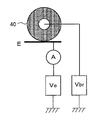
(2-1) ブラシ状ローラ40のブラシの抵抗値を計測する抵抗計測手段を備え、所定の抵抗値に達したら第三の工程へ進む(ブラシに付着したトナーが増加すると、ブラシの抵抗値が増加する)。抵抗計測手段としては例えば図11に示すように、ブラシ状ローラ40に当接する電極Eと、その電極Eへ電圧を印加する電源(電極バイアス印加電源)Veと、その電源Veに流れる電流を検知する電流計Aを備えて、所定のタイミングにてブラシバイアス印加電源Vbrによりブラシ状ローラ40に電圧を印加してブラシの抵抗値を計測する。
(2-2) ブラシ状ローラ40のブラシに付着するトナーの量を計測するトナー量計測手段を備え、所定のトナー量に達したら第三の工程へ進む。トナー量計測手段としては、例えば図12に示すように、光の乱反射成分を検出する光センサPDと、透明な電極TEと、その電極に電圧を印加する電源(電極バイアス印加電源)Veを備えて、所定のタイミングにて透明電極TEにトナーが付着する電圧を印加し、透明電極TEに付着したトナーに対して、ブラシ状ローラ40と反対側から光センサPDの発光部d1で光を投射し、その乱反射成分を光センサPDの受光部d2で受光することによって、トナー量を検知することができる(トナー量に応じて乱反射光の強度が増加する)。ここで透明電極TEに付着するトナー量はブラシ状ローラ40のブラシに付着しているトナー量と比例すると考えて、ブラシに付着したトナー量を検知する。
(2) Control using direct detection means There are the following two types of control using direct detection means.
(2-1) A resistance measuring unit for measuring the resistance value of the brush of the
(2-2) A toner amount measuring means for measuring the amount of toner adhering to the brush of the brush-
以上に説明したように、本実施例の画像形成装置では、帯電量制御手段であるブラシ状ローラ40を、感光体1と帯電ローラ2のどちらか一方のみに接触させるような接離機構を設けたことにより、転写残トナーの帯電量適正化と帯電ローラ2のクリーニングという2つの機能を一つの部材で行うことができるようになり、小型化と低コスト化が達成される。それにより、感光体上の転写残トナーの帯電量が正常化することで転写残トナーが帯電ローラ2により付着しづらくなり、さらに帯電ローラ2に付着してしまった場合にもブラシ状ローラ40が帯電ローラ2に接触する際に回収され、再度感光体1へと戻すことができる。
As described above, in the image forming apparatus according to the present exemplary embodiment, a contact / separation mechanism is provided so that the
また、本実施例の画像形成装置では、転写手段にて転写されずに感光体上に残った転写残トナーは、現像装置5が現像と同時に回収するので、所謂クリーナレス構成にすることで感光体周りの排トナー機構をなくすことができ、装置の大幅な小型化が図れる。また、転写残トナーを再利用することでランニングコストを削減でき、さらなる低コスト化が図れる。また、排トナーを大幅に削減でき、環境負荷低減にも寄与することができる。
Further, in the image forming apparatus of this embodiment, the transfer residual toner that is not transferred by the transfer unit and remains on the photosensitive member is collected by the developing
さらに本実施例の画像形成装置では、接離機構によるブラシ状ローラ40の帯電ローラ2への接触は、非作像時に行われ、非作像時においてのみブラシ状ローラ40と帯電ローラ2を接触させることで、帯電ローラ2の放電を妨げることなく帯電ローラ2に付着したトナーをクリーニングすることができる。また、転写残トナーの発生する作像時には常にブラシ状ローラ40は感光体1に接触しており、帯電ローラ2への帯電量が適正でないトナーの進入を極力少なくすることができる。
Further, in the image forming apparatus of this embodiment, the contact of the
さらに本実施例の画像形成装置では、帯電量制御手段を例えばブラシ状ローラ40とすることにより、回転数によりブラシ状ローラ40とトナーとの摺擦回数を変えて摩擦帯電性をコントロールすることができる。よって感光体1においては過剰にトナーを帯電させることなく適度に帯電することができる。また、過剰にトナーを帯電すると鏡像力により感光体1からトナーが離れづらくなり、結果としてトナー固着や残像が引き起こされるが、上記の構成によりこれらの不具合がなくなる。また、帯電ローラ2においては回転により摺擦力を高めて確実に帯電ローラ2からトナーを回収することができる。
Further, in the image forming apparatus of the present embodiment, the charge amount control means is, for example, the brush-
さらに本実施例の画像形成装置では、カウンター方向にてブラシ状ローラ40と帯電ローラ2が当接するため、ブラシ状ローラ40と帯電ローラ2の接触回数が順方向よりも多くなり、トナーの回収効率が高い。また、同時にブラシ状ローラが帯電ローラ表面を適度に研磨することでトナーフィルミングの防止になる。
Further, in the image forming apparatus of this embodiment, since the
さらに本実施例の画像形成装置では、ブラシ状ローラ40が感光体1と接触しているときに、ブラシ状ローラ40に印加される電圧Vbr1は、対向する感光体1の表面電位をVpcとすると、Vbr1<Vpcの関係を満たすようにしており、ブラシ状ローラ40に印加するバイアスを感光体1の表面電位よりも小さくすることで、ブラシ状ローラ40を通過する転写残トナーに対して摩擦帯電の他に電荷注入をすることができ、より帯電量の制御が効率よく行われる。また、ブラシ状ローラ40通過中にも逆極性のまま正常化されないトナーは電界により一度ブラシ中に保持されるので、帯電ローラ2に付着することが無い。
Further, in the image forming apparatus of this embodiment, when the brush-
さらに本実施例の画像形成装置では、ブラシ状ローラ40が帯電ローラ2と接触しているときに、ブラシ状ローラ40に印加される電圧Vbr2は、対向する帯電ローラ2の芯金の電位をVcとすると、Vbr2<Vcの関係を満たすようにしており、帯電ローラ2に付着したトナーは逆極性の転写残トナーであるが、ブラシ状ローラ40に印加するバイアスを帯電ローラ2の芯金の電位よりも小さくすることで、ブラシ状ローラ40を通過する際に付着トナーを帯電ローラ2からブラシ状ローラ40へと電界により回収することができる。
Furthermore, in the image forming apparatus of this embodiment, when the
さらに本実施例の画像形成装置では、非作像時においてブラシ状ローラ40が感光体1と接触しているときに、ブラシ状ローラ40に印加される電圧Vbr3は、対向する感光体1の表面電位をVpcとすると、Vbr3>Vpcの関係を満たすように設定されるモード(排出モード)を備えたことにより、非作像時において、ブラシ状ローラ40に一時的に保持されている逆極性トナーを感光体1へ排出するような電界が形成されるようにブラシ状ローラ40に電圧を印加することで、ブラシ状ローラ40中のトナーが排出されてブラシ状ローラ40がリフレッシュされるので、長期的に感光体上の転写残トナーの帯電量適正化、帯電ローラ2の付着トナーの回収を繰り返し行うことができる。
Further, in the image forming apparatus of the present embodiment, when the
次に、以上に説明した構成の画像形成装置に用いるトナーについて説明する。
本実施例の画像形成装置に好適に用いられるトナーは、少なくとも、窒素原子を含む官能基を有するポリエステルプレポリマー、ポリエステル、着色剤、離型剤とを有機溶媒中に分散させたトナー材料液を、水系溶媒中で架橋及び/又は伸長反応させて得られるトナーである。以下に、トナーの構成材料及び製造方法について説明する。
Next, toner used in the image forming apparatus having the above-described configuration will be described.
The toner suitably used in the image forming apparatus of the present embodiment includes a toner material liquid in which at least a polyester prepolymer having a functional group containing a nitrogen atom, a polyester, a colorant, and a release agent are dispersed in an organic solvent. A toner obtained by crosslinking and / or elongation reaction in an aqueous solvent. Hereinafter, the constituent material and the manufacturing method of the toner will be described.
(ポリエステル)
ポリエステルは、多価アルコール化合物と多価カルボン酸化合物との重縮合反応によって得られる。
多価アルコール化合物(PO)としては、2価アルコール(DIO)および3価以上の多価アルコール(TO)が挙げられ、(DIO)単独、または(DIO)と少量の(TO)との混合物が好ましい。2価アルコール(DIO)としては、アルキレングリコール(エチレングリコール、1,2−プロピレングリコール、1,3−プロピレングリコール、1,4−ブタンジオール、1,6−ヘキサンジオールなど);アルキレンエーテルグリコール(ジエチレングリコール、トリエチレングリコール、ジプロピレングリコール、ポリエチレングリコール、ポリプロピレングリコール、ポリテトラメチレンエーテルグリコールなど);脂環式ジオール(1,4−シクロヘキサンジメタノール、水素添加ビスフェノールAなど);ビスフェノール類(ビスフェノールA、ビスフェノールF、ビスフェノールSなど);上記脂環式ジオールのアルキレンオキサイド(エチレンオキサイド、プロピレンオキサイド、ブチレンオキサイドなど)付加物;上記ビスフェノール類のアルキレンオキサイド(エチレンオキサイド、プロピレンオキサイド、ブチレンオキサイドなど)付加物などが挙げられる。これらのうち好ましいものは、炭素数2〜12のアルキレングリコールおよびビスフェノール類のアルキレンオキサイド付加物であり、特に好ましいものはビスフェノール類のアルキレンオキサイド付加物、およびこれと炭素数2〜12のアルキレングリコールとの併用である。3価以上の多価アルコール(TO)としては、3〜8価またはそれ以上の多価脂肪族アルコール(グリセリン、トリメチロールエタン、トリメチロールプロパン、ペンタエリスリトール、ソルビトールなど);3価以上のフェノール類(トリスフェノールPA、フェノールノボラック、クレゾールノボラックなど);上記3価以上のポリフェノール類のアルキレンオキサイド付加物などが挙げられる。
(polyester)
The polyester is obtained by a polycondensation reaction between a polyhydric alcohol compound and a polycarboxylic acid compound.
Examples of the polyhydric alcohol compound (PO) include dihydric alcohol (DIO) and trihydric or higher polyhydric alcohol (TO). (DIO) alone or a mixture of (DIO) and a small amount of (TO) preferable. Examples of the dihydric alcohol (DIO) include alkylene glycol (ethylene glycol, 1,2-propylene glycol, 1,3-propylene glycol, 1,4-butanediol, 1,6-hexanediol, etc.); alkylene ether glycol (diethylene glycol) , Triethylene glycol, dipropylene glycol, polyethylene glycol, polypropylene glycol, polytetramethylene ether glycol, etc.); alicyclic diols (1,4-cyclohexanedimethanol, hydrogenated bisphenol A, etc.); bisphenols (bisphenol A, bisphenol) F, bisphenol S, etc.); alkylene oxide (ethylene oxide, propylene oxide, butylene oxide, etc.) adduct of the above alicyclic diol; Alkylene oxide bisphenol (ethylene oxide, propylene oxide, butylene oxide, etc.), etc. adducts. Among them, preferred are alkylene glycols having 2 to 12 carbon atoms and alkylene oxide adducts of bisphenols, and particularly preferred are alkylene oxide adducts of bisphenols and alkylene glycols having 2 to 12 carbon atoms. It is a combined use. The trihydric or higher polyhydric alcohol (TO) includes 3 to 8 or higher polyhydric aliphatic alcohols (glycerin, trimethylolethane, trimethylolpropane, pentaerythritol, sorbitol, etc.); trihydric or higher phenols (Trisphenol PA, phenol novolak, cresol novolak, etc.); and alkylene oxide adducts of the above trivalent or higher polyphenols.
多価カルボン酸(PC)としては、2価カルボン酸(DIC)および3価以上の多価カルボン酸(TC)が挙げられ、(DIC)単独、および(DIC)と少量の(TC)との混合物が好ましい。2価カルボン酸(DIC)としては、アルキレンジカルボン酸(コハク酸、アジピン酸、セバシン酸など);アルケニレンジカルボン酸(マレイン酸、フマール酸など);芳香族ジカルボン酸(フタル酸、イソフタル酸、テレフタル酸、ナフタレンジカルボン酸など)などが挙げられる。これらのうち好ましいものは、炭素数4〜20のアルケニレンジカルボン酸および炭素数8〜20の芳香族ジカルボン酸である。3価以上の多価カルボン酸(TC)としては、炭素数9〜20の芳香族多価カルボン酸(トリメリット酸、ピロメリット酸など)などが挙げられる。なお、多価カルボン酸(PC)として
は、上述のものの酸無水物または低級アルキルエステル(メチルエステル、エチルエステル、イソプロピルエステルなど)を用いて多価アルコール(PO)と反応させてもよい。
Examples of the polyvalent carboxylic acid (PC) include divalent carboxylic acid (DIC) and trivalent or higher polyvalent carboxylic acid (TC). (DIC) alone and (DIC) with a small amount of (TC) Mixtures are preferred. Divalent carboxylic acids (DIC) include alkylene dicarboxylic acids (succinic acid, adipic acid, sebacic acid, etc.); alkenylene dicarboxylic acids (maleic acid, fumaric acid, etc.); aromatic dicarboxylic acids (phthalic acid, isophthalic acid, terephthalic acid) And naphthalenedicarboxylic acid). Of these, preferred are alkenylene dicarboxylic acids having 4 to 20 carbon atoms and aromatic dicarboxylic acids having 8 to 20 carbon atoms. Examples of the trivalent or higher polyvalent carboxylic acid (TC) include aromatic polycarboxylic acids having 9 to 20 carbon atoms (such as trimellitic acid and pyromellitic acid). In addition, as polyhydric carboxylic acid (PC), you may make it react with polyhydric alcohol (PO) using the above-mentioned acid anhydride or lower alkyl ester (Methyl ester, ethyl ester, isopropyl ester, etc.).
多価アルコール(PO)と多価カルボン酸(PC)の比率は、水酸基[OH]とカルボキシル基[COOH]の当量比[OH]/[COOH]として、通常2/1〜1/1、好ましくは1.5/1〜1/1、さらに好ましくは1.3/1〜1.02/1である。 The ratio of the polyhydric alcohol (PO) to the polycarboxylic acid (PC) is usually 2/1 to 1/1, preferably as the equivalent ratio [OH] / [COOH] of the hydroxyl group [OH] and the carboxyl group [COOH]. Is 1.5 / 1 to 1/1, more preferably 1.3 / 1 to 1.02 / 1.
多価アルコール(PO)と多価カルボン酸(PC)の重縮合反応は、テトラブトキシチタネート、ジブチルチンオキサイドなど公知のエステル化触媒の存在下、150〜280℃に加熱し、必要により減圧としながら生成する水を留去して、水酸基を有するポリエステルを得る。ポリエステルの水酸基価は5以上であることが好ましく、ポリエステルの酸価は通常1〜30、好ましくは5〜20である。酸価を持たせることで負帯電性となりやすく、さらには記録紙への定着時、記録紙とトナーの親和性がよく低温定着性が向上する。しかし、酸価が30を超えると帯電の安定性、特に環境変動に対し悪化傾向がある。 The polycondensation reaction between a polyhydric alcohol (PO) and a polycarboxylic acid (PC) is carried out in the presence of a known esterification catalyst such as tetrabutoxytitanate or dibutyltin oxide, and heated to 150 to 280 ° C. while reducing the pressure as necessary. The produced water is distilled off to obtain a polyester having a hydroxyl group. The hydroxyl value of the polyester is preferably 5 or more, and the acid value of the polyester is usually 1 to 30, preferably 5 to 20. By giving an acid value, it tends to be negatively charged, and furthermore, when fixing to a recording paper, the affinity between the recording paper and the toner is good and the low-temperature fixability is improved. However, when the acid value exceeds 30, there is a tendency to deteriorate with respect to the stability of charging, particularly environmental fluctuation.
また、重量平均分子量1万〜40万、好ましくは2万〜20万である。重量平均分子量が1万未満では、耐オフセット性が悪化するため好ましくない。また、40万を超えると低温定着性が悪化するため好ましくない。 The weight average molecular weight is 10,000 to 400,000, preferably 20,000 to 200,000. A weight average molecular weight of less than 10,000 is not preferable because offset resistance deteriorates. On the other hand, if it exceeds 400,000, the low-temperature fixability is deteriorated.
ポリエステルには、上記の重縮合反応で得られる未変性ポリエステルの他に、ウレア変性のポリエステルが好ましく含有される。ウレア変性のポリエステルは、上記の重縮合反応で得られるポリエステルの末端のカルボキシル基や水酸基等と多価イソシアネート化合物(PIC)とを反応させ、イソシアネート基を有するポリエステルプレポリマー(A)を得、これとアミン類との反応により分子鎖が架橋及び/又は伸長されて得られるものである。 In addition to the unmodified polyester obtained by the above polycondensation reaction, the polyester preferably contains a urea-modified polyester. The urea-modified polyester is obtained by reacting a terminal carboxyl group or hydroxyl group of the polyester obtained by the above polycondensation reaction with a polyvalent isocyanate compound (PIC) to obtain a polyester prepolymer (A) having an isocyanate group. It is obtained by cross-linking and / or extending the molecular chain by the reaction of the amine with amines.
多価イソシアネート化合物(PIC)としては、脂肪族多価イソシアネート(テトラメチレンジイソシアネート、ヘキサメチレンジイソシアネート、2,6−ジイソシアナトメチルカプロエートなど);脂環式ポリイソシアネート(イソホロンジイソシアネート、シクロヘキシルメタンジイソシアネートなど);芳香族ジイソシアネート(トリレンジイソシアネート、ジフェニルメタンジイソシアネートなど);芳香脂肪族ジイソシアネート(α,α,α’,α’−テトラメチルキシリレンジイソシアネートなど);イソシアネート類;前記ポリイソシアネートをフェノール誘導体、オキシム、カプロラクタムなどでブロックしたもの;およびこれら2種以上の併用が挙げられる。 Examples of the polyvalent isocyanate compound (PIC) include aliphatic polyisocyanates (tetramethylene diisocyanate, hexamethylene diisocyanate, 2,6-diisocyanatomethylcaproate, etc.); alicyclic polyisocyanates (isophorone diisocyanate, cyclohexylmethane diisocyanate, etc.) ); Aromatic diisocyanates (tolylene diisocyanate, diphenylmethane diisocyanate, etc.); araliphatic diisocyanates (α, α, α ′, α′-tetramethylxylylene diisocyanate, etc.); isocyanates; phenol derivatives, oximes, polyisocyanates; Those blocked with caprolactam or the like; and combinations of two or more of these.
多価イソシアネート化合物(PIC)の比率は、イソシアネート基[NCO]と、水酸基を有するポリエステルの水酸基[OH]の当量比[NCO]/[OH]として、通常5/1〜1/1、好ましくは4/1〜1.2/1、さらに好ましくは2.5/1〜1.5/1である。[NCO]/[OH]が5を超えると低温定着性が悪化する。[NCO]のモル比が1未満では、ウレア変性ポリエステルを用いる場合、そのエステル中のウレア含量が低くなり、耐ホットオフセット性が悪化する。 The ratio of the polyvalent isocyanate compound (PIC) is usually 5/1 to 1/1, preferably as an equivalent ratio [NCO] / [OH] of the isocyanate group [NCO] and the hydroxyl group [OH] of the polyester having a hydroxyl group. 4/1 to 1.2 / 1, more preferably 2.5 / 1 to 1.5 / 1. When [NCO] / [OH] exceeds 5, low-temperature fixability deteriorates. When the molar ratio of [NCO] is less than 1, when a urea-modified polyester is used, the urea content in the ester is lowered and hot offset resistance is deteriorated.
イソシアネート基を有するポリエステルプレポリマー(A)中の多価イソシアネート化合物(PIC)構成成分の含有量は、通常0.5〜40wt%、好ましくは1〜30wt%、さらに好ましくは2〜20wt%である。0.5wt%未満では、耐ホットオフセット性が悪化するとともに、耐熱保存性と低温定着性の両立の面で不利になる。また、40wt%を超えると低温定着性が悪化する。 The content of the polyvalent isocyanate compound (PIC) component in the polyester prepolymer (A) having an isocyanate group is usually 0.5 to 40 wt%, preferably 1 to 30 wt%, more preferably 2 to 20 wt%. . If it is less than 0.5 wt%, the hot offset resistance deteriorates, and it is disadvantageous in terms of both heat-resistant storage stability and low-temperature fixability. On the other hand, if it exceeds 40 wt%, the low-temperature fixability deteriorates.
イソシアネート基を有するポリエステルプレポリマー(A)中の1分子当たりに含有されるイソシアネート基は、通常1個以上、好ましくは、平均1.5〜3個、さらに好ましくは、平均1.8〜2.5個である。1分子当たり1個未満では、ウレア変性ポリエステルの分子量が低くなり、耐ホットオフセット性が悪化する。 The number of isocyanate groups contained per molecule in the polyester prepolymer (A) having an isocyanate group is usually 1 or more, preferably 1.5 to 3 on average, more preferably 1.8 to 2 on average. Five. If it is less than 1 per molecule, the molecular weight of the urea-modified polyester will be low, and the hot offset resistance will deteriorate.
次に、ポリエステルプレポリマー(A)と反応させるアミン類(B)としては、2価アミン化合物(B1)、3価以上の多価アミン化合物(B2)、アミノアルコール(B3)、アミノメルカプタン(B4)、アミノ酸(B5)、およびB1〜B5のアミノ基をブロックしたもの(B6)などが挙げられる。 Next, as amines (B) to be reacted with the polyester prepolymer (A), a divalent amine compound (B1), a trivalent or higher polyvalent amine compound (B2), an amino alcohol (B3), an amino mercaptan (B4) ), Amino acid (B5), and amino acid block of B1 to B5 (B6).
2価アミン化合物(B1)としては、芳香族ジアミン(フェニレンジアミン、ジエチルトルエンジアミン、4,4’−ジアミノジフェニルメタンなど);脂環式ジアミン(4,4’−ジアミノ−3,3’−ジメチルジシクロヘキシルメタン、ジアミンシクロヘキサン、イソホロンジアミンなど);および脂肪族ジアミン(エチレンジアミン、テトラメチレンジアミン、ヘキサメチレンジアミンなど)などが挙げられる。3価以上の多価アミン化合物(B2)としては、ジエチレントリアミン、トリエチレンテトラミンなどが挙げられる。アミノアルコール(B3)としては、エタノールアミン、ヒドロキシエチルアニリンなどが挙げられる。アミノメルカプタン(B4)としては、アミノエチルメルカプタン、アミノプロピルメルカプタンなどが挙げられる。アミノ酸(B5)としては、アミノプロピオン酸、アミノカプロン酸などが挙げられる。B1〜B5のアミノ基をブロックしたもの(B6)としては、前記B1〜B5のアミン類とケトン類(アセトン、メチルエチルケトン、メチルイソブチルケトンなど)から得られるケチミン化合物、オキサゾリジン化合物などが挙げられる。これらアミン類(B)のうち好ましいものは、B1およびB1と少量のB2の混合物である。 Examples of the divalent amine compound (B1) include aromatic diamines (phenylenediamine, diethyltoluenediamine, 4,4′-diaminodiphenylmethane, etc.); alicyclic diamines (4,4′-diamino-3,3′-dimethyldicyclohexyl). Methane, diamine cyclohexane, isophorone diamine, etc.); and aliphatic diamines (ethylene diamine, tetramethylene diamine, hexamethylene diamine, etc.) and the like. Examples of the trivalent or higher polyvalent amine compound (B2) include diethylenetriamine and triethylenetetramine. Examples of amino alcohol (B3) include ethanolamine and hydroxyethylaniline. Examples of amino mercaptan (B4) include aminoethyl mercaptan and aminopropyl mercaptan. Examples of the amino acid (B5) include aminopropionic acid and aminocaproic acid. Examples of the compound (B6) obtained by blocking the amino group of B1 to B5 include ketimine compounds and oxazolidine compounds obtained from the amines of B1 to B5 and ketones (acetone, methyl ethyl ketone, methyl isobutyl ketone, etc.). Among these amines (B), preferred are B1 and a mixture of B1 and a small amount of B2.
アミン類(B)の比率は、イソシアネート基を有するポリエステルプレポリマー(A)中のイソシアネート基[NCO]と、アミン類(B)中のアミノ基[NHx]の当量比[NCO]/[NHx]として、通常1/2〜2/1、好ましくは1.5/1〜1/1.5、さらに好ましくは1.2/1〜1/1.2である。[NCO]/[NHx]が2を超えたり1/2未満では、ウレア変性ポリエステルの分子量が低くなり、耐ホットオフセット性が悪化する。 The ratio of amines (B) is equivalent to the equivalent ratio [NCO] / [NHx] of isocyanate groups [NCO] in the polyester prepolymer (A) having isocyanate groups and amino groups [NHx] in amines (B). Is usually 1/2 to 2/1, preferably 1.5 / 1 to 1 / 1.5, more preferably 1.2 / 1 to 1 / 1.2. When [NCO] / [NHx] is more than 2 or less than 1/2, the molecular weight of the urea-modified polyester is lowered, and the hot offset resistance is deteriorated.
また、ウレア変性ポリエステル中には、ウレア結合と共にウレタン結合を含有していてもよい。ウレア結合含有量とウレタン結合含有量のモル比は、通常100/0〜10/90であり、好ましくは80/20〜20/80、さらに好ましくは、60/40〜30/70である。ウレア結合のモル比が10%未満では、耐ホットオフセット性が悪化する。 The urea-modified polyester may contain a urethane bond together with a urea bond. The molar ratio of the urea bond content to the urethane bond content is usually 100/0 to 10/90, preferably 80/20 to 20/80, and more preferably 60/40 to 30/70. When the molar ratio of the urea bond is less than 10%, the hot offset resistance is deteriorated.
ウレア変性ポリエステルは、ワンショット法などにより製造される。多価アルコール(PO)と多価カルボン酸(PC)を、テトラブトキシチタネート、ジブチルチンオキサイドなど公知のエステル化触媒の存在下、150〜280℃に加熱し、必要により減圧としながら生成する水を留去して、水酸基を有するポリエステルを得る。次いで40〜140℃にて、これに多価イソシアネート(PIC)を反応させ、イソシアネート基を有するポリエステルプレポリマー(A)を得る。さらにこの(A)にアミン類(B)を0〜140℃にて反応させ、ウレア変性ポリエステルを得る。 The urea-modified polyester is produced by a one-shot method or the like. Polyhydric alcohol (PO) and polyvalent carboxylic acid (PC) are heated to 150-280 ° C. in the presence of a known esterification catalyst such as tetrabutoxytitanate, dibutyltin oxide, etc., and water generated while reducing the pressure as necessary. Distill off to obtain a polyester having a hydroxyl group. Subsequently, at 40-140 degreeC, this is made to react with polyvalent isocyanate (PIC), and the polyester prepolymer (A) which has an isocyanate group is obtained. Further, this (A) is reacted with amines (B) at 0 to 140 ° C. to obtain a urea-modified polyester.
(PIC)を反応させる際、及び(A)と(B)を反応させる際には、必要により溶剤を用いることもできる。使用可能な溶剤としては、芳香族溶剤(トルエン、キシレンなど);ケトン類(アセトン、メチルエチルケトン、メチルイソブチルケトンなど);エステル類(酢酸エチルなど);アミド類(ジメチルホルムアミド、ジメチルアセトアミドなど)およびエーテル類(テトラヒドロフランなど)などのイソシアネート(PIC)に対して不活性なものが挙げられる。 When reacting (PIC) and when reacting (A) and (B), a solvent may be used if necessary. Usable solvents include aromatic solvents (toluene, xylene, etc.); ketones (acetone, methyl ethyl ketone, methyl isobutyl ketone, etc.); esters (ethyl acetate, etc.); amides (dimethylformamide, dimethylacetamide, etc.) and ethers And those inert to isocyanates (PIC), such as tetrahydrofuran (such as tetrahydrofuran).
また、ポリエステルプレポリマー(A)とアミン類(B)との架橋及び/又は伸長反応には、必要により反応停止剤を用い、得られるウレア変性ポリエステルの分子量を調整することができる。反応停止剤としては、モノアミン(ジエチルアミン、ジブチルアミン、ブチルアミン、ラウリルアミンなど)、およびそれらをブロックしたもの(ケチミン化合物)などが挙げられる。 In addition, in the crosslinking and / or extension reaction between the polyester prepolymer (A) and the amines (B), a reaction terminator can be used as necessary to adjust the molecular weight of the resulting urea-modified polyester. Examples of the reaction terminator include monoamines (diethylamine, dibutylamine, butylamine, laurylamine, etc.), and those obtained by blocking them (ketimine compounds).
ウレア変性ポリエステルの重量平均分子量は、通常1万以上、好ましくは2万〜1000万、さらに好ましくは3万〜100万である。1万未満では耐ホットオフセット性が悪化する。ウレア変性ポリエステル等の数平均分子量は、先の未変性ポリエステルを用いる場合は特に限定されるものではなく、前記重量平均分子量とするのに得やすい数平均分子量でよい。ウレア変性ポリエステルを単独で使用する場合は、その数平均分子量は、通常2000〜15000、好ましくは2000〜10000、さらに好ましくは2000〜8000である。20000を超えると低温定着性およびフルカラー装置に用いた場合の光沢性が悪化する。 The weight average molecular weight of the urea-modified polyester is usually 10,000 or more, preferably 20,000 to 10,000,000, and more preferably 30,000 to 1,000,000. If it is less than 10,000, the hot offset resistance deteriorates. The number average molecular weight of the urea-modified polyester or the like is not particularly limited when the above-mentioned unmodified polyester is used, and may be a number average molecular weight that can be easily obtained to obtain the weight average molecular weight. When the urea-modified polyester is used alone, its number average molecular weight is usually 2000-15000, preferably 2000-10000, more preferably 2000-8000. When it exceeds 20000, the low-temperature fixability and the glossiness when used in a full-color apparatus are deteriorated.
未変性ポリエステルとウレア変性ポリエステルとを併用することで、低温定着性およびフルカラー画像形成装置100に用いた場合の光沢性が向上するので、ウレア変性ポリエステルを単独で使用するよりも好ましい。なお、未変性ポリエステルはウレア結合以外の化学結合で変性されたポリエステルを含んでも良い。
By using the unmodified polyester and the urea-modified polyester in combination, the low-temperature fixability and the gloss when used in the full-color
未変性ポリエステルとウレア変性ポリエステルとは、少なくとも一部が相溶していることが低温定着性、耐ホットオフセット性の面で好ましい。従って、未変性ポリエステルとウレア変性ポリエステルとは類似の組成であることが好ましい。 The unmodified polyester and the urea-modified polyester are preferably at least partially compatible with each other in terms of low-temperature fixability and hot offset resistance. Therefore, it is preferable that the unmodified polyester and the urea-modified polyester have a similar composition.
また、未変性ポリエステルとウレア変性ポリエステルとの重量比は、通常20/80〜95/5、好ましくは70/30〜95/5、さらに好ましくは75/25〜95/5、特に好ましくは80/20〜93/7である。ウレア変性ポリエステルの重量比が5%未満では、耐ホットオフセット性が悪化するとともに、耐熱保存性と低温定着性の両立の面で不利になる。 The weight ratio of unmodified polyester to urea-modified polyester is usually 20/80 to 95/5, preferably 70/30 to 95/5, more preferably 75/25 to 95/5, and particularly preferably 80 /. 20-93 / 7. When the weight ratio of the urea-modified polyester is less than 5%, the hot offset resistance is deteriorated, and it is disadvantageous in terms of both heat-resistant storage stability and low-temperature fixability.
未変性ポリエステルとウレア変性ポリエステルとを含むバインダー樹脂のガラス転移点(Tg)は、通常45〜65℃、好ましくは45〜60℃である。45℃未満ではトナーの耐熱性が悪化し、65℃を超えると低温定着性が不十分となる。
また、ウレア変性ポリエステルは、得られるトナー母体粒子の表面に存在しやすいため、公知のポリエステル系トナーと比較して、ガラス転移点が低くても耐熱保存性が良好な傾向を示す。
The glass transition point (Tg) of the binder resin containing unmodified polyester and urea-modified polyester is usually 45 to 65 ° C, preferably 45 to 60 ° C. If it is less than 45 ° C., the heat resistance of the toner deteriorates, and if it exceeds 65 ° C., the low-temperature fixability becomes insufficient.
In addition, since the urea-modified polyester is likely to be present on the surface of the obtained toner base particles, the heat-resistant storage stability tends to be good even when the glass transition point is low as compared with known polyester-based toners.
(着色剤)
着色剤としては、公知の染料及び顔料が全て使用でき、例えば、カーボンブラック、ニグロシン染料、鉄黒、ナフトールイエローS、ハンザイエロー(10G、5G、G)、カドミュウムイエロー、黄色酸化鉄、黄土、黄鉛、チタン黄、ポリアゾイエロー、オイルイエロー、ハンザイエロー(GR、A、RN、R)、ピグメントイエローL、ベンジジンイエロー(G、GR)、パーマネントイエロー(NCG)、バルカンファストイエロー(5G、R)、タートラジンレーキ、キノリンイエローレーキ、アンスラザンイエローBGL、イソインドリノンイエロー、ベンガラ、鉛丹、鉛朱、カドミュウムレッド、カドミュウムマーキュリレッド、アンチモン朱、パーマネントレッド4R、パラレッド、ファイセーレッド、パラクロルオルトニトロアニリンレッド、リソールファストスカーレットG、ブリリアントファストスカーレット、ブリリアントカーンミンBS、パーマネントレッド(F2R、F4R、FRL、FRLL、F4RH)、ファストスカーレットVD、ベルカンファストルビンB、ブリリアントスカーレットG、リソールルビンGX、パーマネントレッドF5R、ブリリアントカーミン6B、ピグメントスカーレット3B、ボルドー5B、トルイジンマルーン、パーマネントボルドーF2K、ヘリオボルドーBL、ボルドー10B、ボンマルーンライト、ボンマルーンメジアム、エオシンレーキ、ローダミンレーキB、ローダミンレーキY、アリザリンレーキ、チオインジゴレッドB、チオインジゴマルーン、オイルレッド、キナクリドンレッド、ピラゾロンレッド、ポリアゾレッド、クロームバーミリオン、ベンジジンオレンジ、ペリノンオレンジ、オイルオレンジ、コバルトブルー、セルリアンブルー、アルカリブルーレーキ、ピーコックブルーレーキ、ビクトリアブルーレーキ、無金属フタロシアニンブルー、フタロシアニンブルー、ファストスカイブルー、インダンスレンブルー(RS、BC)、インジゴ、群青、紺青、アントラキノンブルー、ファストバイオレットB、メチルバイオレットレーキ、コバルト紫、マンガン紫、ジオキサンバイオレット、アントラキノンバイオレット、クロムグリーン、ジンクグリーン、酸化クロム、ピリジアン、エメラルドグリーン、ピグメントグリーンB、ナフトールグリーンB、グリーンゴールド、アシッドグリーンレーキ、マラカイトグリーンレーキ、フタロシアニングリーン、アントラキノングリーン、酸化チタン、亜鉛華、リトボン及びそれらの混合物が使用できる。着色剤の含有量はトナーに対して通常1〜15重量%、好ましくは3〜10重量%である。
(Coloring agent)
As the colorant, all known dyes and pigments can be used. For example, carbon black, nigrosine dye, iron black, naphthol yellow S, Hansa yellow (10G, 5G, G), cadmium yellow, yellow iron oxide, ocher , Yellow lead, titanium yellow, polyazo yellow, oil yellow, Hansa yellow (GR, A, RN, R), pigment yellow L, benzidine yellow (G, GR), permanent yellow (NCG), Vulcan fast yellow (5G, R), Tartrazine Lake, Quinoline Yellow Lake, Anthrazan Yellow BGL, Isoindolinone Yellow, Bengala, Red Dan, Lead Zhu, Cadmium Red, Cadmium Mercury Red, Antimon Zhu, Permanent Red 4R, Para Red, Phi Sayred, Parachlor Ortonito Aniline Red, Resol Fast Scarlet G, Brilliant Fast Scarlet, Brilliant Carmine B, Permanent Red (F2R, F4R, FRL, FRLL, F4RH), Fast Scarlet VD, Belkan Fast Rubin B, Brilliant Scarlet G, Resol Rubin GX, Permanent Red F5R , Brilliant Carmine 6B, Pigment Scarlet 3B, Bordeaux 5B, Toluidine Maroon, Permanent Bordeaux F2K, Helio Bordeaux BL, Bordeaux 10B, Bon Maroon Light, Bon Maroon Medium, Eosin Lake, Rhodamine Lake B, Rhodamine Lake Y, Alizarin Lake, Thio Indigo Red B, Thioindigo Maroon, Oil Red, Quinacridone Red, Pyrazolone Red Polyazo Red, Chrome Vermillion, Benzidine Orange, Perinone Orange, Oil Orange, Cobalt Blue, Cerulean Blue, Alkaline Blue Lake, Peacock Blue Lake, Victoria Blue Lake, Metal Free Phthalocyanine Blue, Phthalocyanine Blue, Fast Sky Blue, Indanthrene Blue (RS, BC), indigo, ultramarine blue, bitumen, anthraquinone blue, fast violet B, methyl violet lake, cobalt purple, manganese purple, dioxane violet, anthraquinone violet, chrome green, zinc green, chromium oxide, pyridian, emerald green, pigment Green B, Naphthol Green B, Green Gold, Acid Green Lake, Malachite Green Lake, Lid Russian nin green, anthraquinone green, titanium oxide, zinc white, litbon and mixtures thereof can be used. The content of the colorant is usually 1 to 15% by weight, preferably 3 to 10% by weight, based on the toner.
着色剤は樹脂と複合化されたマスターバッチとして用いることもできる。マスターバッチの製造、またはマスターバッチとともに混練されるバインダー樹脂としては、ポリスチレン、ポリ−p−クロロスチレン、ポリビニルトルエンなどのスチレン及びその置換体の重合体、あるいはこれらとビニル化合物との共重合体、ポリメチルメタクリレート、ポリブチルメタクリレート、ポリ塩化ビニル、ポリ酢酸ビニル、ポリエチレン、ポリプロピレン、ポリエステル、エポキシ樹脂、エポキシポリオール樹脂、ポリウレタン、ポリアミド、ポリビニルブチラール、ポリアクリル酸樹脂、ロジン、変性ロジン、テルペン樹脂、脂肪族又は脂環族炭化水素樹脂、芳香族系石油樹脂、塩素化パラフィン、パラフィンワックスなどが挙げられ、単独あるいは混合して使用できる。 The colorant can also be used as a master batch combined with a resin. As a binder resin to be kneaded together with the production of the master batch or the master batch, a polymer of styrene such as polystyrene, poly-p-chlorostyrene, polyvinyl toluene or the like, or a copolymer of these and a vinyl compound, Polymethyl methacrylate, polybutyl methacrylate, polyvinyl chloride, polyvinyl acetate, polyethylene, polypropylene, polyester, epoxy resin, epoxy polyol resin, polyurethane, polyamide, polyvinyl butyral, polyacrylic acid resin, rosin, modified rosin, terpene resin, fat Aromatic or alicyclic hydrocarbon resins, aromatic petroleum resins, chlorinated paraffins, paraffin waxes and the like can be mentioned, and these can be used alone or in combination.
(荷電制御剤)
荷電制御剤としては公知のものが使用でき、例えばニグロシン系染料、トリフェニルメタン系染料、クロム含有金属錯体染料、モリブデン酸キレート顔料、ローダミン系染料、アルコキシ系アミン、4級アンモニウム塩(フッ素変性4級アンモニウム塩を含む)、アルキルアミド、燐の単体または化合物、タングステンの単体または化合物、フッ素系活性剤、サリチル酸金属塩及び、サリチル酸誘導体の金属塩等である。具体的にはニグロシン系染料のボントロン03、4級アンモニウム塩のボントロンP−51、含金属アゾ染料のボントロンS−34、オキシナフトエ酸系金属錯体のE−82、サリチル酸系金属錯体のE−84、フェノール系縮合物のE−89(以上、オリエント化学工業社製)、4級アンモニウム塩モリブデン錯体のTP−302、TP−415(以上、保土谷化学工業社製)、4級アンモニウム塩のコピーチャージPSY VP2038、トリフェニルメタン誘導体のコピーブルーPR、4級アンモニウム塩のコピーチャージ NEG VP2036、コピーチャージ NX VP434(以上、ヘキスト社製)、LRA−901、ホウ素錯体であるLR−147(日本カーリット社製)、銅フタロシアニン、ペリレン、キナクリドン、アゾ系顔料、その他スルホン酸基、カルボキシル基、4級アンモニウム塩等の官能基を有する高分子系の化合物が挙げられる。このうち、特にトナーを負極性に制御する物質が好ましく使用される。
(Charge control agent)
Known charge control agents can be used, such as nigrosine dyes, triphenylmethane dyes, chromium-containing metal complex dyes, molybdate chelate pigments, rhodamine dyes, alkoxy amines, quaternary ammonium salts (fluorine-modified 4 Secondary ammonium salts or compounds, tungsten simple substances or compounds, fluorine activators, salicylic acid metal salts, and metal salts of salicylic acid derivatives. Specifically, Bontron 03 of a nigrosine dye, Bontron P-51 of a quaternary ammonium salt, Bontron S-34 of a metal-containing azo dye, E-82 of an oxynaphthoic acid metal complex, E-84 of a salicylic acid metal complex , Phenolic condensate E-89 (above, Orient Chemical Industries, Ltd.), quaternary ammonium salt molybdenum complex TP-302, TP-415 (above, Hodogaya Chemical Co., Ltd.), quaternary ammonium salt copy Charge PSY VP2038, copy blue PR of triphenylmethane derivative, copy charge of quaternary ammonium salt NEG VP2036, copy charge NX VP434 (manufactured by Hoechst), LRA-901, LR-147 which is a boron complex (Nippon Carlit) Manufactured), copper phthalocyanine, perylene, quinacridone, azo series Fee, a sulfonic acid group, a carboxyl group, and polymer compounds having a functional group such as quaternary ammonium salts. Of these, substances that control the negative polarity of the toner are particularly preferably used.
荷電制御剤の使用量は、バインダー樹脂の種類、必要に応じて使用される添加剤の有無、分散方法を含めたトナー製造方法によって決定されるもので、一義的に限定されるものではないが、好ましくはバインダー樹脂100重量部に対して、0.1〜10重量部の範囲で用いられる。好ましくは、0.2〜5重量部の範囲がよい。10重量部を超える場合にはトナーの帯電性が大きすぎ、荷電制御剤の効果を減退させ、現像ローラとの静電的吸引力が増大し、現像剤の流動性低下や、画像濃度の低下を招く。 The amount of charge control agent used is determined by the type of binder resin, the presence or absence of additives used as necessary, and the toner production method including the dispersion method, and is not uniquely limited. Preferably, it is used in the range of 0.1 to 10 parts by weight with respect to 100 parts by weight of the binder resin. The range of 0.2 to 5 parts by weight is preferable. When the amount exceeds 10 parts by weight, the chargeability of the toner is too high, the effect of the charge control agent is reduced, the electrostatic attraction with the developing roller is increased, the developer fluidity is lowered, and the image density is lowered. Invite.
(離型剤)
離型剤としては、融点が50〜120℃の低融点のワックスが、バインダー樹脂との分散の中でより離型剤として効果的に定着ローラとトナー界面との間で働き、これにより定着ローラにオイルの如き離型剤を塗布することなく高温オフセットに対し効果を示す。このようなワックス成分としては、以下のものが挙げられる。ロウ類及びワックス類としては、カルナバワックス、綿ロウ、木ロウ、ライスワックス等の植物系ワックス、ミツロウ、ラノリン等の動物系ワックス、オゾケライト、セルシン等の鉱物系ワックス、及びパラフィン、マイクロクリスタリン、ペトロラタム等の石油ワックス等が挙げられる。また、これら天然ワックスの外に、フィッシャー・トロプシュワックス、ポリエチレンワックス等の合成炭化水素ワックス、エステル、ケトン、エーテル等の合成ワックス等が挙げられる。さらに、12−ヒドロキシステアリン酸アミド、ステアリン酸アミド、無水フタル酸イミド、塩素化炭化水素等の脂肪酸アミド及び、低分子量の結晶性高分子樹脂である、ポリ−n−ステアリルメタクリレート、ポリ−n−ラウリルメタクリレート等のポリアクリレートのホモ重合体あるいは共重合体(例えば、n−ステアリルアクリレート−エチルメタクリレートの共重合体等)等、側鎖に長いアルキル基を有する結晶性高分子等も用いることができる。
(Release agent)
As a release agent, a low melting point wax having a melting point of 50 to 120 ° C. works more effectively as a release agent in the dispersion with the binder resin between the fixing roller and the toner interface. The effect on high temperature offset is exhibited without applying a release agent such as oil. Examples of such a wax component include the following. Waxes and waxes include plant waxes such as carnauba wax, cotton wax, wood wax, rice wax, animal waxes such as beeswax and lanolin, mineral waxes such as ozokerite and cercin, and paraffin, microcrystalline, and petrolatum. And petroleum wax. In addition to these natural waxes, synthetic hydrocarbon waxes such as Fischer-Tropsch wax and polyethylene wax, and synthetic waxes such as esters, ketones, and ethers can be used. Furthermore, fatty acid amides such as 12-hydroxystearic acid amide, stearic acid amide, phthalic anhydride imide, chlorinated hydrocarbon, and low molecular weight crystalline polymer resin, poly-n-stearyl methacrylate, poly-n- A crystalline polymer having a long alkyl group in the side chain such as a homopolymer or copolymer of polyacrylate such as lauryl methacrylate (for example, a copolymer of n-stearyl acrylate-ethyl methacrylate, etc.) can also be used. .
荷電制御剤、離型剤はマスターバッチ、バインダー樹脂とともに溶融混練することもできるし、もちろん有機溶剤に溶解、分散する際に加えても良い。 The charge control agent and the release agent can be melt-kneaded together with the master batch and the binder resin, and of course, they may be added when dissolved and dispersed in the organic solvent.
(外添剤)
トナー粒子の流動性や現像性、帯電性を補助するための外添剤として、無機微粒子が好ましく用いられる。この無機微粒子の一次粒子径は、5×10⁻³〜2μmであることが好ましく、特に5×10⁻³〜0.5μmであることが好ましい。また、BET法による比表面積は、20〜500m2/gであることが好ましい。この無機微粒子の使用割合は、トナーの0.01〜5wt%であることが好ましく、特に0.01〜2.0wt%であることが好ましい。
(External additive)
Inorganic fine particles are preferably used as an external additive for assisting the fluidity, developability and chargeability of the toner particles. The primary particle diameter of the inorganic fine particles is preferably 5 × 10 −3 to 2 μm, and particularly preferably 5 × 10 −3 to 0.5 μm. Moreover, it is preferable that the specific surface area by BET method is 20-500 m <2> / g. The use ratio of the inorganic fine particles is preferably 0.01 to 5 wt% of the toner, and particularly preferably 0.01 to 2.0 wt%.
無機微粒子の具体例としては、例えばシリカ、アルミナ、酸化チタン、チタン酸バリウム、チタン酸マグネシウム、チタン酸カルシウム、チタン酸ストロンチウム、酸化亜鉛、酸化スズ、ケイ砂、クレー、雲母、ケイ灰石、ケイソウ土、酸化クロム、酸化セリウム、ベンガラ、三酸化アンチモン、酸化マグネシウム、酸化ジルコニウム、硫酸バリウム、炭酸バリウム、炭酸カルシウム、炭化ケイ素、窒化ケイ素などを挙げることができる。中でも、流動性付与剤としては、疎水性シリカ微粒子と疎水性酸化チタン微粒子を併用するのが好ましい。特に両微粒子の平均粒径が5×10⁻²μm以下のものを使用して攪拌混合を行った場合、トナーとの静電力、ファンデルワールス力は格段に向上することより、所望の帯電レベルを得るために行われる現像装置内部の攪拌混合によっても、トナーから流動性付与剤が脱離することなく、ホタルなどが発生しない良好な画像品質が得られて、さらに転写残トナーの低減が図られる。 Specific examples of the inorganic fine particles include, for example, silica, alumina, titanium oxide, barium titanate, magnesium titanate, calcium titanate, strontium titanate, zinc oxide, tin oxide, quartz sand, clay, mica, wollastonite, diatomaceous earth. Examples include soil, chromium oxide, cerium oxide, bengara, antimony trioxide, magnesium oxide, zirconium oxide, barium sulfate, barium carbonate, calcium carbonate, silicon carbide, and silicon nitride. Among these, as the fluidity imparting agent, it is preferable to use hydrophobic silica fine particles and hydrophobic titanium oxide fine particles in combination. In particular, when stirring and mixing are performed using particles having an average particle size of 5 × 10⁻² μm or less, the electrostatic force and van der Waals force with the toner are remarkably improved. Even when stirring and mixing inside the developing device is performed, a fluidity-imparting agent is not detached from the toner, a good image quality that does not cause fireflies and the like is obtained, and a reduction in residual toner is further achieved. .
酸化チタン微粒子は、環境安定性、画像濃度安定性に優れている反面、帯電立ち上がり特性の悪化傾向にあることより、酸化チタン微粒子添加量がシリカ微粒子添加量よりも多くなると、この副作用の影響が大きくなることが考えられる。しかし、疎水性シリカ微粒子及び疎水性酸化チタン微粒子の添加量が0.3〜1.5wt%の範囲では、帯電立ち上がり特性が大きく損なわれず、所望の帯電立ち上がり特性が得られ、すなわち、プリントやコピーの繰り返しを行っても、安定した画像品質が得られる。 Titanium oxide fine particles are excellent in environmental stability and image density stability, but have a tendency to deteriorate the charge rise characteristics. Therefore, if the amount of titanium oxide fine particles added is larger than the amount of silica fine particles added, this side effect is affected. It can be considered large. However, when the addition amount of the hydrophobic silica fine particles and the hydrophobic titanium oxide fine particles is in the range of 0.3 to 1.5 wt%, the charge rising characteristics are not greatly impaired, and the desired charge rising characteristics can be obtained, that is, printing or copying. Even if the above is repeated, stable image quality can be obtained.
次に、トナーの製造方法について説明する。ここでは、好ましい製造方法について示すが、これに限られるものではない。 Next, a toner manufacturing method will be described. Here, although a preferable manufacturing method is shown, it is not limited to this.
(トナーの製造方法)
(1)着色剤、未変性ポリエステル、イソシアネート基を有するポリエステルプレポリマー、離型剤を有機溶媒中に分散させトナー材料液を作る。
有機溶媒は、沸点が100℃未満の揮発性であることが、トナー母体粒子形成後の除去が容易である点から好ましい。具体的には、トルエン、キシレン、ベンゼン、四塩化炭素、塩化メチレン、1,2−ジクロロエタン、1,1,2−トリクロロエタン、トリクロロエチレン、クロロホルム、モノクロロベンゼン、ジクロロエチリデン、酢酸メチル、酢酸エチル、メチルエチルケトン、メチルイソブチルケトンなどを単独あるいは2種以上組合せて用いることができる。特に、トルエン、キシレン等の芳香族系溶媒および塩化メチレン、1,2−ジクロロエタン、クロロホルム、四塩化炭素等のハロゲン化炭化水素が好ましい。有機溶媒の使用量は、ポリエステルプレポリマー100重量部に対し、通常0〜300重量部、好ましくは0〜100重量部、さらに好ましくは25〜70重量部である。
(Toner production method)
(1) A toner material solution is prepared by dispersing a colorant, unmodified polyester, a polyester prepolymer having an isocyanate group, and a release agent in an organic solvent.
The organic solvent is preferably volatile with a boiling point of less than 100 ° C. from the viewpoint of easy removal after toner base particle formation. Specifically, toluene, xylene, benzene, carbon tetrachloride, methylene chloride, 1,2-dichloroethane, 1,1,2-trichloroethane, trichloroethylene, chloroform, monochlorobenzene, dichloroethylidene, methyl acetate, ethyl acetate, methyl ethyl ketone, Methyl isobutyl ketone and the like can be used alone or in combination of two or more. In particular, aromatic solvents such as toluene and xylene and halogenated hydrocarbons such as methylene chloride, 1,2-dichloroethane, chloroform, and carbon tetrachloride are preferable. The usage-amount of an organic solvent is 0-300 weight part normally with respect to 100 weight part of polyester prepolymers, Preferably it is 0-100 weight part, More preferably, it is 25-70 weight part.
(2)トナー材料液を界面活性剤、樹脂微粒子の存在下、水系媒体中で乳化させる。
水系媒体は、水単独でも良いし、アルコール(メタノール、イソプロピルアルコール、エチレングリコールなど)、ジメチルホルムアミド、テトラヒドロフラン、セルソルブ類(メチルセルソルブど)、低級ケトン類(アセトン、メチルエチルケトンなど)などの有機溶媒を含むものであってもよい。
トナー材料液100重量部に対する水系媒体の使用量は、通常50〜2000重量部、好ましくは100〜1000重量部である。50重量部未満ではトナー材料液の分散状態が悪く、所定の粒径のトナー粒子が得られない。20000重量部を超えると経済的でない。
(2) The toner material liquid is emulsified in an aqueous medium in the presence of a surfactant and resin fine particles.
The aqueous medium may be water alone, or an organic solvent such as alcohol (methanol, isopropyl alcohol, ethylene glycol, etc.), dimethylformamide, tetrahydrofuran, cellosolves (methylcellosolve, etc.), lower ketones (acetone, methyl ethyl ketone, etc.). It may be included.
The amount of the aqueous medium used relative to 100 parts by weight of the toner material liquid is usually 50 to 2000 parts by weight, preferably 100 to 1000 parts by weight. If the amount is less than 50 parts by weight, the dispersion state of the toner material liquid is poor, and toner particles having a predetermined particle diameter cannot be obtained. If it exceeds 20000 parts by weight, it is not economical.
また、水系媒体中の分散を良好にするために、界面活性剤、樹脂微粒子等の分散剤を適宜加える。
界面活性剤としては、アルキルベンゼンスルホン酸塩、α−オレフィンスルホン酸塩、リン酸エステルなどのアニオン性界面活性剤、アルキルアミン塩、アミノアルコール脂肪酸誘導体、ポリアミン脂肪酸誘導体、イミダゾリンなどのアミン塩型や、アルキルトリメチルアンモニム塩、ジアルキルジメチルアンモニウム塩、アルキルジメチルベンジルアンモニウム塩、ピリジニウム塩、アルキルイソキノリニウム塩、塩化ベンゼトニウムなどの4級アンモニウム塩型のカチオン性界面活性剤、脂肪酸アミド誘導体、多価アルコール誘導体などの非イオン界面活性剤、例えばアラニン、ドデシルジ(アミノエチル)グリシン、ジ(オクチルアミノエチル)グリシンやN−アルキル−N,N−ジメチルアンモニウムべタインなどの両性界面活性剤が挙げられる。
Further, in order to improve the dispersion in the aqueous medium, a dispersant such as a surfactant and resin fine particles is appropriately added.
As surfactants, anionic surfactants such as alkylbenzene sulfonates, α-olefin sulfonates, phosphate esters, alkylamine salts, amino alcohol fatty acid derivatives, polyamine fatty acid derivatives, amine salt types such as imidazoline, Quaternary ammonium salt type cationic surfactants such as alkyltrimethylammonium salts, dialkyldimethylammonium salts, alkyldimethylbenzylammonium salts, pyridinium salts, alkylisoquinolinium salts, benzethonium chloride, fatty acid amide derivatives, polyhydric alcohols Nonionic surfactants such as derivatives, for example, amphoteric surfactants such as alanine, dodecyldi (aminoethyl) glycine, di (octylaminoethyl) glycine and N-alkyl-N, N-dimethylammonium betaine And the like.
また、フルオロアルキル基を有する界面活性剤を用いることにより、非常に少量でその効果をあげることができる。好ましく用いられるフルオロアルキル基を有するアニオン性界面活性剤としては、炭素数2〜10のフルオロアルキルカルボン酸及びその金属塩、パーフルオロオクタンスルホニルグルタミン酸ジナトリウム、3−[ω−フルオロアルキル(C6〜C11)オキシ]−1−アルキル(C3〜C4)スルホン酸ナトリウム、3−[ω−フルオロアルカノイル(C6〜C8)−N−エチルアミノ]−1−プロパンスルホン酸ナトリウム、フルオロアルキル(C11〜C20)カルボン酸及び金属塩、パーフルオロアルキルカルボン酸(C7〜C13)及びその金属塩、パーフルオロアルキル(C4〜C12)スルホン酸及びその金属塩、パーフルオロオクタンスルホン酸ジエタノールアミド、N−プロピル−N−(2−ヒドロキシエチル)パーフルオロオクタンスルホンアミド、パーフルオロアルキル(C6〜C10)スルホンアミドプロピルトリメチルアンモニウム塩、パーフルオロアルキル(C6〜C10)−N−エチルスルホニルグリシン塩、モノパーフルオロアルキル(C6〜C16)エチルリン酸エステルなどが挙げられる。 Further, by using a surfactant having a fluoroalkyl group, the effect can be obtained in a very small amount. Preferred anionic surfactants having a fluoroalkyl group include fluoroalkyl carboxylic acids having 2 to 10 carbon atoms and metal salts thereof, disodium perfluorooctanesulfonyl glutamate, 3- [ω-fluoroalkyl (C6-C11 ) Oxy] -1-alkyl (C3-C4) sodium sulfonate, 3- [ω-fluoroalkanoyl (C6-C8) -N-ethylamino] -1-propanesulfonic acid sodium, fluoroalkyl (C11-C20) carvone Acids and metal salts, perfluoroalkylcarboxylic acids (C7 to C13) and metal salts thereof, perfluoroalkyl (C4 to C12) sulfonic acids and metal salts thereof, perfluorooctanesulfonic acid diethanolamide, N-propyl-N- ( 2-Hydroxyethyl) Perful Olooctanesulfonamide, perfluoroalkyl (C6-C10) sulfonamidopropyltrimethylammonium salt, perfluoroalkyl (C6-C10) -N-ethylsulfonylglycine salt, monoperfluoroalkyl (C6-C16) ethyl phosphate, etc. Can be mentioned.
商品名としては、サーフロンS−111、S−112、S−113(旭硝子社製)、フロラードFC−93、FC−95、FC−98、FC−129(住友3M社製)、ユニダインDS−101、DS−102(ダイキン工業社製)、メガファックF−110、F−120、F−113、F−191、F−812、F−833(大日本インキ社製)、エクトップEF−102、103、104、105、112、123A、123B、306A、501、201、204、(トーケムプロダクツ社製)、フタージェントF−100、F150(ネオス社製)などが挙げられる。 Product names include Surflon S-111, S-112, S-113 (Asahi Glass Co., Ltd.), Florard FC-93, FC-95, FC-98, FC-129 (Sumitomo 3M Co., Ltd.), Unidyne DS-101. DS-102 (manufactured by Daikin Industries, Ltd.), Megafac F-110, F-120, F-113, F-191, F-812, F-833 (manufactured by Dainippon Ink, Inc.), Xtop EF-102, 103, 104, 105, 112, 123A, 123B, 306A, 501, 201, 204 (manufactured by Tochem Products), and Fgentent F-100, F150 (manufactured by Neos).
また、カチオン性界面活性剤としては、フルオロアルキル基を右する脂肪族1級、2級もしくは2級アミン酸、パーフルオロアルキル(C6−C10)スルホンアミドプロピルトリメチルアンモニウム塩などの脂肪族4級アンモニウム塩、ベンザルコニウム塩、塩化ベンゼトニウム、ピリジニウム塩、イミダゾリニウム塩、商品名としてはサーフロンS−121(旭硝子社製)、フロラードFC−135(住友3M社製)、ユニダインDS−202(ダイキンエ業杜製)、メガファックF−150、F−824(大日本インキ社製)、エクトップEF−132(トーケムプロダクツ社製)、フタージェントF−300(ネオス社製)などが挙げられる。 Moreover, as the cationic surfactant, aliphatic quaternary ammonium such as aliphatic primary, secondary or secondary amic acid, perfluoroalkyl (C6-C10) sulfonamidopropyltrimethylammonium salt which has a right fluoroalkyl group is used. Salt, benzalkonium salt, benzethonium chloride, pyridinium salt, imidazolinium salt, trade names include Surflon S-121 (manufactured by Asahi Glass), Florard FC-135 (manufactured by Sumitomo 3M), Unidyne DS-202 (Daikin Industries) Smoke), Megafac F-150, F-824 (Dainippon Ink Co., Ltd.), Xtop EF-132 (Tochem Products), Footage F-300 (Neos), and the like.
樹脂微粒子は、水系媒体中で形成されるトナー母体粒子を安定化させるために加えられる。このために、トナー母体粒子の表面上に存在する被覆率が10〜90%の範囲になるように加えられることが好ましい。例えば、ポリメタクリル酸メチル微粒子1μm、及び3μm、ポリスチレン微粒子0.5μm及び2μm、ポリ(スチレン―アクリロニトリル)微粒子1μm、商品名では、PB−200H(花王社製)、SGP(総研社製)、テクノポリマーSB(積水化成品工業社製)、SGP−3G(総研社製)、ミクロパール(積水ファインケミカル社製)等がある。
また、リン酸三カルシウム、炭酸カルシウム、酸化チタン、コロイダルシリカ、ヒドロキシアパタイト等の無機化合物分散剤も用いることができる。
The resin fine particles are added to stabilize the toner base particles formed in the aqueous medium. For this reason, it is preferable to add so that the coverage existing on the surface of the toner base particles is in the range of 10 to 90%. For example, polymethyl methacrylate
In addition, inorganic compound dispersants such as tricalcium phosphate, calcium carbonate, titanium oxide, colloidal silica, and hydroxyapatite can also be used.
上記の樹脂微粒子、無機化合物分散剤と併用して使用可能な分散剤として、高分子系保護コロイドにより分散液滴を安定化させても良い。例えばアクリル酸、メタクリル酸、α−シアノアクリル酸、α−シアノメタクリル酸、イタコン酸、クロトン酸、フマール酸、マレイン酸または無水マレイン酸などの酸類、あるいは水酸基を含有する(メタ)アクリル系単量体、例えばアクリル酸−β−ヒドロキシエチル、メタクリル酸−β−ヒドロキシエチル、アクリル酸−β−ヒドロキシプロビル、メタクリル酸−β−ヒドロキシプロピル、アクリル酸−γ−ヒドロキシプロピル、メタクリル酸−γ−ヒドロキシプロピル、アクリル酸−3−クロロ2−ヒドロキシプロビル、メタクリル酸−3−クロロ−2−ヒドロキシプロピル、ジエチレングリコールモノアクリル酸エステル、ジエチレングリコールモノメタクリル酸エステル、グリセリンモノアクリル酸エステル、グリセリンモノメタクリル酸エステル、N−メチロールアクリルアミド、N−メチロールメタクリルアミドなど、ビニルアルコールまたはビニルアルコールとのエーテル類、例えばビニルメチルエーテル、ビニルエチルエーテル、ビニルプロピルエーテルなど、またはビニルアルコールとカルボキシル基を含有する化合物のエステル類、例えば酢酸ビニル、プロピオン酸ビニル、酪酸ビニルなど、アクリルアミド、メタクリルアミド、ジアセトンアクリルアミドあるいはこれらのメチロール化合物、アクリル酸クロライド、メタクリル酸クロライドなどの酸クロライド類、ビニルピリジン、ビニルピロリドン、ビニルイミダゾール、エチレンイミンなどの含窒素化合物、またはその複素環を有するものなどのホモポリマーまたは共重合体、ポリオキシエチレン、ポリオキシプロピレン、ポリオキシエチレンアルキルアミン、ポリオキシプロピレンアルキルアミン、ポリオキシエチレンアルキルアミド、ポリオキシプロピレンアルキルアミド、ポリオキシエチレンノニルフェニルエーテル、ポリオキシエチレンラウリルフェニルエーテル、ポリオキシエチレンステアリルフェニルエステル、ポリオキシエチレンノニルフェニルエステルなどのポリオキシエチレン系、メチルセルロース、ヒドロキシエチルセルロース、ヒドロキシプロピルセルロースなどのセルロース類などが使用できる。 As a dispersant that can be used in combination with the above resin fine particles and inorganic compound dispersant, the dispersed droplets may be stabilized by a polymer protective colloid. For example, acrylic acid, methacrylic acid, α-cyanoacrylic acid, α-cyanomethacrylic acid, itaconic acid, crotonic acid, fumaric acid, maleic acid or maleic anhydride and other (meth) acrylic monomers containing hydroxyl groups Bodies such as acrylic acid-β-hydroxyethyl, methacrylic acid-β-hydroxyethyl, acrylic acid-β-hydroxypropyl, methacrylic acid-β-hydroxypropyl, acrylic acid-γ-hydroxypropyl, methacrylic acid-γ-hydroxy Propyl, acrylic acid-3-chloro-2-hydroxypropyl, methacrylic acid-3-chloro-2-hydroxypropyl, diethylene glycol monoacrylate, diethylene glycol monomethacrylate, glycerol monoacrylate, glycerol monomethacrylate Luric acid esters, N-methylol acrylamide, N-methylol methacrylamide, etc., vinyl alcohol or ethers with vinyl alcohol, such as vinyl methyl ether, vinyl ethyl ether, vinyl propyl ether, or compounds containing vinyl alcohol and a carboxyl group Esters such as vinyl acetate, vinyl propionate, vinyl butyrate, acrylamide, methacrylamide, diacetone acrylamide or their methylol compounds, acid chlorides such as acrylic acid chloride, methacrylic acid chloride, vinyl pyridine, vinyl pyrrolidone, vinyl Nitrogen compounds such as imidazole and ethyleneimine, or homopolymers or copolymers such as those having a heterocyclic ring thereof, polyoxyethylene, poly Xoxypropylene, polyoxyethylene alkylamine, polyoxypropylene alkylamine, polyoxyethylene alkylamide, polyoxypropylene alkylamide, polyoxyethylene nonylphenyl ether, polyoxyethylene lauryl phenyl ether, polyoxyethylene stearyl phenyl ester, polyoxy Polyoxyethylenes such as ethylene nonylphenyl ester, celluloses such as methyl cellulose, hydroxyethyl cellulose, and hydroxypropyl cellulose can be used.
分散の方法としては特に限定されるものではないが、低速せん断式、高速せん断式、摩擦式、高圧ジェット式、超音波などの公知の設備が適用できる。この中でも、分散体の粒径を2〜20μmにするために高速せん断式が好ましい。高速せん断式分散機を使用した場合、回転数は特に限定はないが、通常1000〜30000rpm、好ましくは5000〜20000rpmである。分散時間は特に限定はないが、バッチ方式の場合は、通常0.1〜5分である。分散時の温度としては、通常、0〜150℃(加圧下)、好ましくは40〜98℃である。
The dispersion method is not particularly limited, and known equipment such as a low-speed shear method, a high-speed shear method, a friction method, a high-pressure jet method, and an ultrasonic wave can be applied. Among these, the high-speed shearing method is preferable in order to make the particle size of the
(3)乳化液の作製と同時に、アミン類(B)を添加し、イソシアネート基を有するポリエステルプレポリマー(A)との反応を行わせる。
この反応は、分子鎖の架橋及び/又は伸長を伴う。反応時間は、ポリエステルプレポリマー(A)の有するイソシアネート基構造とアミン類(B)との反応性により選択されるが、通常10分〜40時間、好ましくは2〜24時間である。反応温度は、通常、0〜150℃、好ましくは40〜98℃である。また、必要に応じて公知の触媒を使用することができる。具体的にはジブチルチンラウレート、ジオクチルチンラウレートなどが挙げられる。
(3) At the same time as the preparation of the emulsion, the amines (B) are added to cause a reaction with the polyester prepolymer (A) having an isocyanate group.
This reaction involves molecular chain crosslinking and / or elongation. The reaction time is selected depending on the reactivity between the isocyanate group structure of the polyester prepolymer (A) and the amines (B), but is usually 10 minutes to 40 hours, preferably 2 to 24 hours. The reaction temperature is generally 0 to 150 ° C, preferably 40 to 98 ° C. Moreover, a well-known catalyst can be used as needed. Specific examples include dibutyltin laurate and dioctyltin laurate.
(4)反応終了後、乳化分散体(反応物)から有機溶媒を除去し、洗浄、乾燥してトナー母体粒子を得る。
有機溶媒を除去するためには、系全体を徐々に層流の攪拌状態で昇温し、一定の温度域で強い攪拌を与えた後、脱溶媒を行うことで紡錘形のトナー母体粒子が作製できる。また、分散安定剤としてリン酸カルシウム塩などの酸、アルカリに溶解可能な物を用いた場合は、塩酸等の酸により、リン酸カルシウム塩を溶解した後、水洗するなどの方法によって、トナー母体粒子からリン酸カルシウム塩を除去する。その他酵素による分解などの操作によっても除去できる。
(4) After completion of the reaction, the organic solvent is removed from the emulsified dispersion (reactant), washed and dried to obtain toner base particles.
In order to remove the organic solvent, the temperature of the entire system is gradually raised in a laminar stirring state, and after giving strong stirring in a certain temperature range, the solvent base is removed to produce spindle-shaped toner base particles. . Further, when an acid such as calcium phosphate salt or an alkali-soluble material is used as the dispersion stabilizer, the calcium phosphate salt is dissolved from the toner base particles by a method such as dissolving the calcium phosphate salt with an acid such as hydrochloric acid and washing with water. Remove. It can also be removed by operations such as enzymatic degradation.
(5)上記で得られたトナー母体粒子に、荷電制御剤を打ち込み、ついで、シリカ微粒子、酸化チタン微粒子等の無機微粒子を外添させ、トナーを得る。
荷電制御剤の打ち込み、及び無機微粒子の外添は、ミキサー等を用いた公知の方法によって行われる。
これにより、小粒径であって、粒径分布のシャープなトナーを容易に得ることができる。さらに、有機溶媒を除去する工程で強い攪拌を与えることで、真球状からラクビーボール状の間の形状を制御することができ、さらに、表面のモフォロジーも滑らかなものから梅干形状の間で制御することができる。
(5) A charge control agent is injected into the toner base particles obtained above, and then inorganic fine particles such as silica fine particles and titanium oxide fine particles are externally added to obtain a toner.
The injection of the charge control agent and the external addition of the inorganic fine particles are performed by a known method using a mixer or the like.
Thereby, a toner having a small particle size and a sharp particle size distribution can be easily obtained. Furthermore, by giving strong agitation in the process of removing the organic solvent, the shape between the true spherical shape and the rugby ball shape can be controlled, and the surface morphology is also controlled between the smooth shape and the umeboshi shape. be able to.
次に、トナーの形状について説明する。
トナーの形状係数SF−1は100〜180、形状係数SF−2は100〜180の範囲にあることが好ましい。図13(A),(B)は、形状係数SF−1と形状係数SF−2を説明するためにトナーの形状を模式的に表した図である。形状係数SF−1は、トナー形状の丸さの割合を示すものであり、下記の式(1)で表される。これは、トナーを2次元平面に投影してできる形状の最大長MXLNGの二乗を図形面積AREAで除して、100π/4を乗じた値である。
SF−1={(MXLNG)2/AREA}×(100π/4) ・・・式(1)
SF−1の値が100の場合トナーの形状は真球となり、SF−1の値が大きくなるほど不定形になる。
Next, the shape of the toner will be described.
The toner shape factor SF-1 is preferably in the range of 100 to 180, and the shape factor SF-2 is preferably in the range of 100 to 180. FIGS. 13A and 13B are diagrams schematically illustrating the shape of the toner in order to explain the shape factor SF-1 and the shape factor SF-2. The shape factor SF-1 indicates the ratio of the roundness of the toner shape, and is represented by the following formula (1). This is a value obtained by dividing the square of the maximum length MXLNG of the shape formed by projecting toner onto a two-dimensional plane by the figure area AREA and multiplying by 100π / 4.
SF-1 = {(MXLNG) 2 / AREA} × (100π / 4) Formula (1)
When the value of SF-1 is 100, the shape of the toner becomes a true sphere, and becomes larger as the value of SF-1 increases.
また、形状係数SF−2は、トナーの形状の凹凸の割合を示すものであり、下記の式(2)で表される。これは、トナーを2次元平面に投影してできる図形の周長PERIの二乗を図形面積AREAで除して、100/4πを乗じた値である。
SF−2={(PERI)2/AREA}×(100/4π) ・・・式(2)
SF−2の値が100の場合トナー表面に凹凸が存在しなくなり、SF−2の値が大きくなるほどトナー表面の凹凸が顕著になる。
The shape factor SF-2 indicates the ratio of the unevenness of the toner shape, and is represented by the following formula (2). This is a value obtained by dividing the square of the perimeter PERI of the figure formed by projecting the toner onto the two-dimensional plane by the figure area AREA and multiplying by 100 / 4π.
SF-2 = {(PERI) 2 / AREA} × (100 / 4π) (2)
When the value of SF-2 is 100, there is no unevenness on the toner surface, and as the value of SF-2 increases, the unevenness of the toner surface becomes more prominent.
形状係数の測定は、具体的には、走査型電子顕微鏡(S−800:日立製作所製)でトナーの写真を撮り、これを画像解析装置(LUSEX3:ニレコ社製)に導入し該トナーの粒子100個について解析して計算した。
トナーの形状が球形に近くなると、トナーとトナーあるいはトナーと感光体との接触状態が点接触になるために、トナー同士の吸着力は弱くなり、従って流動性が高くなり、また、トナーと感光体との吸着力も弱くなって、転写率は高くなる。一方、形状係数SF−1、SF−2のいずれかが180を超えると、転写率が低下するため好ましくない。
Specifically, the shape factor is measured by taking a photograph of the toner with a scanning electron microscope (S-800: manufactured by Hitachi, Ltd.) and introducing it into an image analyzer (LUSEX3: manufactured by Nireco). 100 pieces were analyzed and calculated.
When the shape of the toner is close to a spherical shape, the contact state between the toner and the toner or the toner and the photosensitive member becomes a point contact, so that the adsorbing force between the toners becomes weak, and thus the fluidity becomes high. The attracting power with the body also becomes weaker, and the transfer rate becomes higher. On the other hand, if any of the shape factors SF-1 and SF-2 exceeds 180, the transfer rate is lowered, which is not preferable.
本発明の画像形成装置では、画像形成に用いられるトナーは、形状係数SF−1で100〜180の範囲にあり、かつ形状係数SF−2で100〜180の範囲にあることにより、トナー形状が球により近づくことで転写率が向上するため、転写残トナー量の極小化が図れるため、より安定なクリーナレスシステムを構成することができる。 In the image forming apparatus of the present invention, the toner used for image formation is in the range of 100 to 180 in terms of the shape factor SF-1 and in the range of 100 to 180 in terms of the shape factor SF-2. Since the transfer rate is improved by approaching the sphere, the amount of residual toner can be minimized, and a more stable cleaner-less system can be configured.
1(1Y、1C、1M、1K):感光体(像担持体)
2:帯電ローラ
3:帯電装置
4:露光装置(潜像形成手段)
5:現像装置(現像手段)
5a:現像ローラ
5b:攪拌搬送スクリュー
6:転写装置(転写手段)
10:中間転写ベルト(中間転写体)
11、12、13:支持ローラ
14(14Y、14C、14M、14K):一次転写ローラ
15:ベルトクリーニング装置
16:二次転写ローラ
20:給紙カセット
21:給紙ローラ
22:レジストローラ対
23:加熱定着装置(定着手段)
24:排紙ローラ
31Y、31C、31M、31K:トナーボトル
40:ブラシ状ローラ(帯電量制御手段)
41:接離手段(接離機構)
1 (1Y, 1C, 1M, 1K): photoconductor (image carrier)
2: Charging roller 3: Charging device 4: Exposure device (latent image forming means)
5: Developing device (developing means)
5a: developing
10: Intermediate transfer belt (intermediate transfer member)
11, 12, 13: Support roller 14 (14Y, 14C, 14M, 14K): Primary transfer roller 15: Belt cleaning device 16: Secondary transfer roller 20: Paper feed cassette 21: Paper feed roller 22: Registration roller pair 23: Heat fixing device (fixing means)
24:
41: Contact / separation means (contact / separation mechanism)
Claims (7)
前記像担持体に近接し非接触にて像担持体表面を帯電する帯電ローラと、
前記像担持体に潜像を形成する潜像形成手段と、
前記像担持体の潜像にトナーを付着させてトナー像として顕像化する現像手段と、
前記像担持体上のトナー像を記録材に直接又は中間転写体を介して転写する転写手段と、
前記像担持体上の転写残トナーの帯電量を制御する帯電量制御手段と、
を少なくとも備えた画像形成装置において、
前記帯電量制御手段を、前記像担持体か前記帯電ローラのどちらかに選択的に接触させるような接離機構と、
前記帯電量制御手段に付着したトナー量を検知する検知手段とを備え、
前記接離機構による前記帯電量制御手段の前記帯電ローラへの接触は、非作像時に行われ、
作像時において前記帯電量制御手段が前記像担持体と接触しているときに、前記帯電量制御手段に印加される電圧Vbr1は、対向する前記像担持体の表面電位をVpcとすると、
Vbr1<Vpc
の関係を満たし、
前記帯電量制御手段が前記帯電ローラと接触しているときに、前記帯電量制御手段に印加される電圧Vbr2は、対向する前記帯電ローラの芯金の電位をVcとすると、
Vbr2<Vc
の関係を満たし、
非作像時において前記帯電量制御手段が前記像担持体と接触しているときに、前記帯電量制御手段に印加される電圧Vbr3は、対向する前記像担持体の表面電位をVpcとすると、
Vbr3>Vpc
の関係を満たすように設定される排出モードを備え、
前記検知手段での検知結果により前記排出モードを実行することを特徴とする画像形成装置。 An image carrier for carrying an electrostatic latent image;
A charging roller that charges the surface of the image carrier in a non-contact manner in proximity to the image carrier;
Latent image forming means for forming a latent image on the image carrier;
Developing means for developing a toner image by attaching toner to the latent image of the image carrier;
Transfer means for transferring the toner image on the image carrier to a recording material directly or via an intermediate transfer member;
Charge amount control means for controlling the charge amount of the transfer residual toner on the image carrier;
In an image forming apparatus comprising at least
A contact / separation mechanism for selectively bringing the charge amount control means into contact with either the image carrier or the charging roller ;
Detecting means for detecting the amount of toner adhering to the charge amount control means ,
The contact of the charge amount control means to the charging roller by the contact / separation mechanism is performed during non-image formation,
When the charge amount control means is in contact with the image carrier at the time of image formation, the voltage Vbr1 applied to the charge amount control means is given by assuming that the surface potential of the opposing image carrier is Vpc.
Vbr1 <Vpc
Satisfy the relationship
When the charge amount control means is in contact with the charging roller, the voltage Vbr2 applied to the charge amount control means is Vc when the potential of the metal core of the opposite charging roller is Vc.
Vbr2 <Vc
Satisfy the relationship
When the charge amount control means is in contact with the image carrier during non-image formation, the voltage Vbr3 applied to the charge amount control means is given by assuming that the surface potential of the opposite image carrier is Vpc.
Vbr3> Vpc
Equipped with a discharge mode set to satisfy the relationship
The image forming apparatus, wherein the discharge mode is executed based on a detection result of the detection unit.
前記転写手段にて転写されずに前記像担持体上に残った転写残トナーは、前記現像手段が現像と同時に回収することを特徴とする画像形成装置。 The image forming apparatus according to claim 1.
An image forming apparatus, wherein the transfer residual toner remaining on the image carrier without being transferred by the transfer means is collected simultaneously with development by the developing means.
前記帯電量制御手段は回転可能なブラシ部材であることを特徴とする画像形成装置。 The image forming apparatus according to claim 1 or 2,
The image forming apparatus according to claim 1, wherein the charge amount control means is a rotatable brush member .
前記帯電量制御手段であるブラシ部材の回転方向は、前記帯電ローラの回転方向と対向位置において反対方向であることを特徴とする画像形成装置。 The image forming apparatus according to claim 3 .
The image forming apparatus according to claim 1, wherein a rotation direction of the brush member serving as the charge amount control unit is opposite to a rotation direction of the charging roller .
画像形成に用いられるトナーは、形状係数SF−1で100〜180の範囲にあり、かつ形状係数SF−2で100〜180の範囲にあることを特徴とする画像形成装置。 The image forming apparatus according to any one of claims 1 to 4, wherein:
An image forming apparatus characterized in that the toner used for image formation is in the range of 100 to 180 in terms of the shape factor SF-1 and in the range of 100 to 180 in terms of the shape factor SF-2 .
前記帯電ローラ、前記現像手段、前記帯電量制御手段のうちの少なくとも一つと、前記像担持体とを一体に構成したことを特徴とするプロセスカートリッジ。 A process cartridge that is mounted on the image forming apparatus according to any one of claims 1 to 5 and configured to be detachable from the image forming apparatus main body.
A process cartridge comprising at least one of the charging roller, the developing unit, and the charge amount control unit, and the image carrier .
該複数のプロセスカートリッジの像担持体上に色の異なるトナー像を形成し、該トナー像を記録材に直接又は中間転写体を介して重ね合わせて転写し、多色またはフルカラー画像を形成することを特徴とする画像形成装置。 A plurality of process cartridges according to claim 6,
Forming toner images of different colors on the image carriers of the plurality of process cartridges, and transferring the toner images onto a recording material directly or via an intermediate transfer member to form a multicolor or full color image An image forming apparatus.
Priority Applications (1)
| Application Number | Priority Date | Filing Date | Title |
|---|---|---|---|
| JP2007131789A JP5055615B2 (en) | 2007-05-17 | 2007-05-17 | Image forming apparatus and process cartridge |
Applications Claiming Priority (1)
| Application Number | Priority Date | Filing Date | Title |
|---|---|---|---|
| JP2007131789A JP5055615B2 (en) | 2007-05-17 | 2007-05-17 | Image forming apparatus and process cartridge |
Publications (2)
| Publication Number | Publication Date |
|---|---|
| JP2008286998A JP2008286998A (en) | 2008-11-27 |
| JP5055615B2 true JP5055615B2 (en) | 2012-10-24 |
Family
ID=40146784
Family Applications (1)
| Application Number | Title | Priority Date | Filing Date |
|---|---|---|---|
| JP2007131789A Expired - Fee Related JP5055615B2 (en) | 2007-05-17 | 2007-05-17 | Image forming apparatus and process cartridge |
Country Status (1)
| Country | Link |
|---|---|
| JP (1) | JP5055615B2 (en) |
Family Cites Families (9)
| Publication number | Priority date | Publication date | Assignee | Title |
|---|---|---|---|---|
| JPH07128954A (en) * | 1993-11-04 | 1995-05-19 | Ricoh Co Ltd | Image forming device and electrification uniforming method therefor |
| JP3002630B2 (en) * | 1994-09-28 | 2000-01-24 | 東芝テック株式会社 | Electrophotographic recording device |
| JPH08254934A (en) * | 1995-03-16 | 1996-10-01 | Canon Inc | Image forming device |
| JP3278800B2 (en) * | 1997-08-29 | 2002-04-30 | キヤノン株式会社 | Image forming device |
| JP4458700B2 (en) * | 2000-03-14 | 2010-04-28 | キヤノン株式会社 | Image forming apparatus and process cartridge |
| JP2002139973A (en) * | 2000-11-06 | 2002-05-17 | Ricoh Co Ltd | Image forming device |
| JP2002311692A (en) * | 2001-04-19 | 2002-10-23 | Fuji Xerox Co Ltd | Image forming device |
| JP2005092146A (en) * | 2003-09-19 | 2005-04-07 | Ricoh Co Ltd | Image forming apparatus, electrifying member, electrifying device, cleaning means and process cartridge |
| JP2007003610A (en) * | 2005-06-21 | 2007-01-11 | Ricoh Co Ltd | Image forming apparatus, multicolor image forming apparatus and process cartridge |
-
2007
- 2007-05-17 JP JP2007131789A patent/JP5055615B2/en not_active Expired - Fee Related
Also Published As
| Publication number | Publication date |
|---|---|
| JP2008286998A (en) | 2008-11-27 |
Similar Documents
| Publication | Publication Date | Title |
|---|---|---|
| JP5429628B2 (en) | Cleaning device and image forming apparatus | |
| US9454126B2 (en) | Cleaning device and image forming apparatus including same | |
| JP2012022049A (en) | Cleaning device and image formation device | |
| JP2012088671A (en) | Image forming apparatus and cleaning device | |
| JP2014048536A (en) | Cleaning device, image forming apparatus, and voltage setting device | |
| JP4585237B2 (en) | Lubricant coating apparatus, process cartridge, and image forming apparatus | |
| JP2006154412A (en) | Image forming apparatus | |
| JP5585878B2 (en) | Cleaning device and image forming apparatus | |
| JP2009145463A (en) | Cleaning device and image forming apparatus | |
| JP2007292996A (en) | Image forming apparatus, process cartridge and toner | |
| JP2011164470A (en) | Cleaning device and image forming apparatus | |
| JP5874957B2 (en) | Cleaning device and image forming apparatus | |
| JP5053767B2 (en) | Image forming apparatus | |
| JP5769045B2 (en) | Cleaning device and image forming apparatus | |
| JP4244147B2 (en) | Image forming apparatus and process cartridge used therefor | |
| JP2005031120A (en) | Image forming apparatus and toner used for the same | |
| JP2013045083A (en) | Cleaning device and image forming apparatus | |
| JP2010039131A (en) | Cleaning device and image forming apparatus | |
| JP4842729B2 (en) | Image forming apparatus control method and image forming apparatus | |
| JP2005099126A (en) | Cleaning device, process cartridge, image forming apparatus, and toner used for the same | |
| JP5055615B2 (en) | Image forming apparatus and process cartridge | |
| JP5761599B2 (en) | Cleaning device and image forming apparatus | |
| JP2008175841A (en) | Image forming apparatus | |
| JP4890365B2 (en) | Developing device, process cartridge, and image forming apparatus | |
| JP4890366B2 (en) | Developing device, process cartridge, and image forming apparatus |
Legal Events
| Date | Code | Title | Description |
|---|---|---|---|
| A621 | Written request for application examination |
Free format text: JAPANESE INTERMEDIATE CODE: A621 Effective date: 20100112 |
|
| A977 | Report on retrieval |
Free format text: JAPANESE INTERMEDIATE CODE: A971007 Effective date: 20111228 |
|
| A131 | Notification of reasons for refusal |
Free format text: JAPANESE INTERMEDIATE CODE: A131 Effective date: 20120110 |
|
| A521 | Written amendment |
Free format text: JAPANESE INTERMEDIATE CODE: A523 Effective date: 20120312 |
|
| TRDD | Decision of grant or rejection written | ||
| A01 | Written decision to grant a patent or to grant a registration (utility model) |
Free format text: JAPANESE INTERMEDIATE CODE: A01 Effective date: 20120703 |
|
| A01 | Written decision to grant a patent or to grant a registration (utility model) |
Free format text: JAPANESE INTERMEDIATE CODE: A01 |
|
| A61 | First payment of annual fees (during grant procedure) |
Free format text: JAPANESE INTERMEDIATE CODE: A61 Effective date: 20120712 |
|
| FPAY | Renewal fee payment (event date is renewal date of database) |
Free format text: PAYMENT UNTIL: 20150810 Year of fee payment: 3 |
|
| R150 | Certificate of patent or registration of utility model |
Ref document number: 5055615 Country of ref document: JP Free format text: JAPANESE INTERMEDIATE CODE: R150 Free format text: JAPANESE INTERMEDIATE CODE: R150 |
|
| LAPS | Cancellation because of no payment of annual fees |