JP5050807B2 - REPRODUCTION DEVICE, DISPLAY DEVICE, REPRODUCTION METHOD, AND DISPLAY METHOD - Google Patents
REPRODUCTION DEVICE, DISPLAY DEVICE, REPRODUCTION METHOD, AND DISPLAY METHOD Download PDFInfo
- Publication number
- JP5050807B2 JP5050807B2 JP2007303186A JP2007303186A JP5050807B2 JP 5050807 B2 JP5050807 B2 JP 5050807B2 JP 2007303186 A JP2007303186 A JP 2007303186A JP 2007303186 A JP2007303186 A JP 2007303186A JP 5050807 B2 JP5050807 B2 JP 5050807B2
- Authority
- JP
- Japan
- Prior art keywords
- signal
- audio signal
- video
- audio
- decoded
- Prior art date
- Legal status (The legal status is an assumption and is not a legal conclusion. Google has not performed a legal analysis and makes no representation as to the accuracy of the status listed.)
- Expired - Fee Related
Links
- 238000000034 method Methods 0.000 title claims description 38
- 230000005236 sound signal Effects 0.000 claims abstract description 172
- 238000012545 processing Methods 0.000 claims abstract description 93
- 238000000926 separation method Methods 0.000 claims abstract description 3
- 230000005540 biological transmission Effects 0.000 claims description 57
- 238000001514 detection method Methods 0.000 claims description 23
- 230000007274 generation of a signal involved in cell-cell signaling Effects 0.000 claims 1
- 230000001934 delay Effects 0.000 abstract description 6
- 238000010586 diagram Methods 0.000 description 20
- 230000004048 modification Effects 0.000 description 16
- 238000012986 modification Methods 0.000 description 16
- 230000008569 process Effects 0.000 description 9
- 239000003990 capacitor Substances 0.000 description 8
- 230000000694 effects Effects 0.000 description 7
- 238000005259 measurement Methods 0.000 description 7
- 230000003111 delayed effect Effects 0.000 description 4
- 230000001172 regenerating effect Effects 0.000 description 4
- 230000000750 progressive effect Effects 0.000 description 3
- 238000005513 bias potential Methods 0.000 description 2
- 230000007175 bidirectional communication Effects 0.000 description 2
- 238000007796 conventional method Methods 0.000 description 2
- 230000006870 function Effects 0.000 description 2
- 230000004044 response Effects 0.000 description 2
- 230000008054 signal transmission Effects 0.000 description 2
- 230000002123 temporal effect Effects 0.000 description 2
- 230000006854 communication Effects 0.000 description 1
- 238000004891 communication Methods 0.000 description 1
- 239000000284 extract Substances 0.000 description 1
- 239000004973 liquid crystal related substance Substances 0.000 description 1
- 238000012423 maintenance Methods 0.000 description 1
- 230000007246 mechanism Effects 0.000 description 1
- 230000008520 organization Effects 0.000 description 1
- 238000003672 processing method Methods 0.000 description 1
- 230000011664 signaling Effects 0.000 description 1
- 230000001360 synchronised effect Effects 0.000 description 1
- 230000007704 transition Effects 0.000 description 1
- 230000000007 visual effect Effects 0.000 description 1
Images


Classifications
-
- H—ELECTRICITY
- H04—ELECTRIC COMMUNICATION TECHNIQUE
- H04N—PICTORIAL COMMUNICATION, e.g. TELEVISION
- H04N5/00—Details of television systems
- H04N5/44—Receiver circuitry for the reception of television signals according to analogue transmission standards
-
- H—ELECTRICITY
- H04—ELECTRIC COMMUNICATION TECHNIQUE
- H04N—PICTORIAL COMMUNICATION, e.g. TELEVISION
- H04N21/00—Selective content distribution, e.g. interactive television or video on demand [VOD]
- H04N21/40—Client devices specifically adapted for the reception of or interaction with content, e.g. set-top-box [STB]; Operations thereof
- H04N21/43—Processing of content or additional data, e.g. demultiplexing additional data from a digital video stream; Elementary client operations, e.g. monitoring of home network or synchronising decoder's clock; Client middleware
- H04N21/44—Processing of video elementary streams, e.g. splicing a video clip retrieved from local storage with an incoming video stream or rendering scenes according to encoded video stream scene graphs
- H04N21/44004—Processing of video elementary streams, e.g. splicing a video clip retrieved from local storage with an incoming video stream or rendering scenes according to encoded video stream scene graphs involving video buffer management, e.g. video decoder buffer or video display buffer
-
- G—PHYSICS
- G11—INFORMATION STORAGE
- G11B—INFORMATION STORAGE BASED ON RELATIVE MOVEMENT BETWEEN RECORD CARRIER AND TRANSDUCER
- G11B20/00—Signal processing not specific to the method of recording or reproducing; Circuits therefor
- G11B20/02—Analogue recording or reproducing
-
- H—ELECTRICITY
- H04—ELECTRIC COMMUNICATION TECHNIQUE
- H04N—PICTORIAL COMMUNICATION, e.g. TELEVISION
- H04N21/00—Selective content distribution, e.g. interactive television or video on demand [VOD]
- H04N21/40—Client devices specifically adapted for the reception of or interaction with content, e.g. set-top-box [STB]; Operations thereof
- H04N21/43—Processing of content or additional data, e.g. demultiplexing additional data from a digital video stream; Elementary client operations, e.g. monitoring of home network or synchronising decoder's clock; Client middleware
- H04N21/4302—Content synchronisation processes, e.g. decoder synchronisation
- H04N21/4307—Synchronising the rendering of multiple content streams or additional data on devices, e.g. synchronisation of audio on a mobile phone with the video output on the TV screen
- H04N21/43072—Synchronising the rendering of multiple content streams or additional data on devices, e.g. synchronisation of audio on a mobile phone with the video output on the TV screen of multiple content streams on the same device
-
- H—ELECTRICITY
- H04—ELECTRIC COMMUNICATION TECHNIQUE
- H04N—PICTORIAL COMMUNICATION, e.g. TELEVISION
- H04N21/00—Selective content distribution, e.g. interactive television or video on demand [VOD]
- H04N21/40—Client devices specifically adapted for the reception of or interaction with content, e.g. set-top-box [STB]; Operations thereof
- H04N21/43—Processing of content or additional data, e.g. demultiplexing additional data from a digital video stream; Elementary client operations, e.g. monitoring of home network or synchronising decoder's clock; Client middleware
- H04N21/439—Processing of audio elementary streams
- H04N21/4392—Processing of audio elementary streams involving audio buffer management
-
- H—ELECTRICITY
- H04—ELECTRIC COMMUNICATION TECHNIQUE
- H04N—PICTORIAL COMMUNICATION, e.g. TELEVISION
- H04N21/00—Selective content distribution, e.g. interactive television or video on demand [VOD]
- H04N21/40—Client devices specifically adapted for the reception of or interaction with content, e.g. set-top-box [STB]; Operations thereof
- H04N21/43—Processing of content or additional data, e.g. demultiplexing additional data from a digital video stream; Elementary client operations, e.g. monitoring of home network or synchronising decoder's clock; Client middleware
- H04N21/442—Monitoring of processes or resources, e.g. detecting the failure of a recording device, monitoring the downstream bandwidth, the number of times a movie has been viewed, the storage space available from the internal hard disk
-
- H—ELECTRICITY
- H04—ELECTRIC COMMUNICATION TECHNIQUE
- H04N—PICTORIAL COMMUNICATION, e.g. TELEVISION
- H04N5/00—Details of television systems
- H04N5/04—Synchronising
-
- H—ELECTRICITY
- H04—ELECTRIC COMMUNICATION TECHNIQUE
- H04N—PICTORIAL COMMUNICATION, e.g. TELEVISION
- H04N5/00—Details of television systems
- H04N5/76—Television signal recording
-
- H—ELECTRICITY
- H04—ELECTRIC COMMUNICATION TECHNIQUE
- H04N—PICTORIAL COMMUNICATION, e.g. TELEVISION
- H04N5/00—Details of television systems
- H04N5/76—Television signal recording
- H04N5/765—Interface circuits between an apparatus for recording and another apparatus
Landscapes
- Engineering & Computer Science (AREA)
- Signal Processing (AREA)
- Multimedia (AREA)
- Computer Networks & Wireless Communication (AREA)
- Databases & Information Systems (AREA)
- Two-Way Televisions, Distribution Of Moving Picture Or The Like (AREA)
- Television Signal Processing For Recording (AREA)
Abstract
Description
本発明は、再生装置および表示装置に関し、特に音声信号や映像信号などのデジタル信号を再生出力する再生装置、表示装置、および、これらにおける処理方法に関する。 The present invention relates to a playback device and a display device, and more particularly to a playback device and a display device that play back and output digital signals such as audio signals and video signals, and a processing method therefor.
近年、音声信号や映像信号などのデジタル信号を扱うAV(Audio/Visual)機器が普及するにつれて、これらAV機器間においてデジタル信号を伝送するためのインターフェースとして様々な方式のものが提案されている。このようなインターフェースとしては、例えば、IEEE(Institute of Electrical and Electronics Engineers)1394規格や、HDMI(High-Definition Multimedia Interface)規格(HDMIは登録商標)などが広く知られている(例えば、特許文献1参照。)。 In recent years, with the spread of AV (Audio / Visual) devices that handle digital signals such as audio signals and video signals, various types of interfaces have been proposed as interfaces for transmitting digital signals between these AV devices. As such an interface, for example, IEEE (Institute of Electrical and Electronics Engineers) 1394 standard, HDMI (High-Definition Multimedia Interface) standard (HDMI is a registered trademark), etc. are widely known (for example, Patent Document 1). reference.).
このようなインターフェースによりAV機器を接続する場合、テレビジョン受像機器により映像を表示するとともに、AVアンプにより音声を出力するという使用形態が想定される。この場合、テレビジョン受像機器における映像処理時間とAVアンプにおける音声処理時間とが異なることにより、映像と音声との間に時間のずれが生じるという問題がある。この問題に対して、例えば、HDMI規格において映像処理に要する処理時間をテレビジョン受像機器からAVアンプに提供し、これに応じて音声信号の処理を遅延させることによって、再生される映像と音声との間の同期(リップシンク)を行うシステムが提案されている(例えば、特許文献2参照。)。
AV機器をHDMI規格により接続する場合、映像信号および音声信号は、TMDS(Transition Minimized Differential Signaling)と呼ばれるシリアル伝送方式により伝送される。このTMDS伝送では、高速に伝送を行うため、伝送方向は片方向になっている。したがって、機器の接続の態様によってはユーザの意図する機器から音声を出力できないおそれがある。また、機器によっては自機器において独立してデジタル信号を復号できない場合があり、この場合には他機器に復号処理を委ねる必要が生じる。この場合においても、上述のリップシンクは考慮されなければならない。 When AV equipment is connected according to the HDMI standard, video signals and audio signals are transmitted by a serial transmission method called TMDS (Transition Minimized Differential Signaling). In this TMDS transmission, since the transmission is performed at high speed, the transmission direction is unidirectional. Therefore, there is a possibility that audio cannot be output from the device intended by the user depending on how the devices are connected. Also, depending on the device, there are cases where the digital signal cannot be decoded independently by the device itself. In this case, it is necessary to entrust the decoding process to another device. Even in this case, the above-mentioned lip sync must be considered.
本発明はこのような状況に鑑みてなされたものであり、HDMI規格のように片方向伝送を基本とするインターフェースを用いるシステムにおいて、映像信号および音声信号の復号処理を柔軟に行うことを目的とする。 The present invention has been made in view of such a situation, and it is an object of the present invention to flexibly perform video signal and audio signal decoding processing in a system using an interface based on one-way transmission such as the HDMI standard. To do.
本発明は、上記課題を解決するためになされたものであり、その第1の側面は、符号化映像信号および符号化音声信号を含むストリーム信号をストリーム生成装置から受信して上記ストリーム信号から上記符号化映像信号と上記符号化音声信号とを分離する分離手段と、上記符号化映像信号を復号して映像信号として映像出力装置に出力する映像信号復号手段と、上記符号化音声信号を復号して音声信号を生成する音声信号復号手段と、上記映像出力装置における上記映像信号の処理に要する時間を映像処理時間として取得して当該映像処理時間に基づいて上記音声信号を遅延させた後に当該音声信号を音声出力装置に供給する音声信号処理手段とを具備することを特徴とする再生装置またはその再生方法である。これにより、ストリーム生成装置から受信したストリーム信号について、映像出力装置における映像信号の処理に要する時間に合わせて音声信号を遅延させるという作用をもたらす。 The present invention has been made to solve the above problems, and a first aspect of the present invention is that a stream signal including an encoded video signal and an encoded audio signal is received from a stream generation device, and the stream signal is transmitted from the stream signal. Separating means for separating the encoded video signal and the encoded audio signal, video signal decoding means for decoding the encoded video signal and outputting it as a video signal to a video output device, and decoding the encoded audio signal Audio signal decoding means for generating an audio signal, and acquiring the time required for processing the video signal in the video output device as the video processing time and delaying the audio signal based on the video processing time, An audio signal processing means for supplying a signal to an audio output device is provided. This brings about the effect that the audio signal is delayed in accordance with the time required for processing the video signal in the video output device for the stream signal received from the stream generation device.
また、この第1の側面において、上記音声信号処理手段は、上記映像出力装置との間に接続された制御信号線路を介して上記映像処理時間を取得してもよい。この制御信号線路は、HDMIケーブルを構成するディスプレイデータチャンネル(DDC)により実現してもよい。 In this first aspect, the audio signal processing means may acquire the video processing time via a control signal line connected to the video output device. This control signal line may be realized by a display data channel (DDC) constituting an HDMI cable.
また、この第1の側面において、上記分離手段は、上記ストリーム生成装置との間に接続されたデータ信号線路を介して上記ストリーム信号を受信してもよい。この場合において、上記ストリーム生成装置が上記映像出力装置に含まれるとしたとき、上記音声信号処理手段は、上記データ信号線路を介して上記映像処理時間を取得してもよい。また、この場合において、上記データ信号線路は、HDMIケーブルを構成するリザーブラインおよびホットプラグ検出ラインにより実現してもよい。 In the first aspect, the separation unit may receive the stream signal via a data signal line connected to the stream generation device. In this case, when the stream generation device is included in the video output device, the audio signal processing means may acquire the video processing time via the data signal line. In this case, the data signal line may be realized by a reserved line and a hot plug detection line constituting an HDMI cable.
また、この第1の側面において、上記音声信号復号手段が上記復号された音声信号を上記映像出力装置に出力して、上記音声信号処理手段が上記映像出力装置から返送された音声信号と上記音声信号復号手段によって復号された上記音声信号との時間上の差分を上記映像処理時間として測定してもよい。これにより、映像出力装置から返送された音声信号と復号された音声信号との時間上の差分に基づいて、復号された音声信号を遅延させるという作用をもたらす。この場合において、上記映像出力装置との間に接続されたデータ信号線路を介して受信した差動信号から上記ストリーム信号を抽出する第1の受信手段と、上記データ信号線路を介して受信した同相信号から上記返送された音声信号を抽出する第2の受信手段とをさらに具備してもよい。これにより、ストリーム信号と音声信号を同じデータ信号線路を介して伝送させるという作用をもたらす。また、この場合において、上記データ信号線路は、HDMIケーブルを構成するリザーブラインおよびホットプラグ検出ラインにより実現してもよい。 In the first aspect, the audio signal decoding unit outputs the decoded audio signal to the video output device, and the audio signal processing unit returns the audio signal and the audio returned from the video output device. The time difference from the audio signal decoded by the signal decoding means may be measured as the video processing time. This brings about the effect that the decoded audio signal is delayed based on the temporal difference between the audio signal returned from the video output device and the decoded audio signal. In this case, the first receiving means for extracting the stream signal from the differential signal received via the data signal line connected to the video output device, and the same received via the data signal line. You may further comprise the 2nd receiving means which extracts the returned audio | voice signal from a phase signal. As a result, the stream signal and the audio signal are transmitted through the same data signal line. In this case, the data signal line may be realized by a reserved line and a hot plug detection line constituting an HDMI cable.
また、本発明の第2の側面は、符号化映像信号および符号化音声信号を含むストリーム信号を生成するストリーム信号生成手段と、他の装置との間の接続状態に関する接続情報を管理する接続情報管理手段と、上記接続情報に基づいて上記ストリーム信号を復号する復号装置が接続されているか否かを判断して上記復号装置が接続されている場合には当該復号装置に上記ストリーム信号を出力するよう切り替えるストリーム信号切替手段と、上記復号装置によって復号された映像信号を受信して表示手段に表示させる表示制御手段と、上記表示制御手段における上記映像信号の処理に要する時間を映像処理時間として上記復号装置に供給する映像処理時間供給手段とを具備することを特徴とする表示装置またはその表示方法である。これにより、他の装置との間の接続状態に応じて他の復号装置に復号処理を依頼させるという作用をもたらす。 The second aspect of the present invention provides connection information for managing connection information relating to a connection state between a stream signal generating unit that generates a stream signal including an encoded video signal and an encoded audio signal, and another device. Based on the connection information, the management means and whether or not the decoding device that decodes the stream signal is connected. If the decoding device is connected, the stream signal is output to the decoding device. The stream signal switching means for switching, the display control means for receiving the video signal decoded by the decoding device and displaying it on the display means, and the time required for processing the video signal in the display control means as the video processing time An image processing time supply means for supplying to a decoding device. This brings about the effect that the other decoding device is requested to perform the decoding process according to the connection state with the other device.
また、この第2の側面において、上記ストリーム信号から上記符号化映像信号と上記符号化音声信号とを分離する分離手段と、上記符号化映像信号を復号して映像信号として生成する映像信号復号手段とをさらに具備し、上記ストリーム信号切替手段は、上記復号装置が接続されていない場合には上記分離手段に上記ストリーム信号を出力するよう切り替え、上記表示制御手段は、上記復号装置が接続されている場合には上記復号装置によって復号された映像信号を上記表示手段に表示させ、上記復号装置が接続されていない場合には上記映像信号復号手段によって復号された映像信号を上記表示手段に表示させてもよい。これにより、表示装置における映像信号復号手段または他の復号装置の何れかに符号化映像信号を選択的に復号させるという作用をもたらす。 Further, in the second aspect, a separating unit that separates the encoded video signal and the encoded audio signal from the stream signal, and a video signal decoding unit that decodes the encoded video signal to generate a video signal. The stream signal switching means is switched to output the stream signal to the separating means when the decoding apparatus is not connected, and the display control means is connected to the decoding apparatus. The video signal decoded by the decoding device is displayed on the display means, and when the decoding device is not connected, the video signal decoded by the video signal decoding means is displayed on the display means. May be. This brings about the effect that the encoded video signal is selectively decoded by either the video signal decoding means or the other decoding device in the display device.
また、この第2の側面において、上記符号化映像信号を復号するn個(nは0以上の整数)の映像信号復号手段をさらに備えてもよい。これにより、上記映像信号復号手段の数より多い映像信号に相当する映像を上記表示手段に表示させるという作用をもたらす。 In the second aspect, the image processing apparatus may further include n (n is an integer greater than or equal to 0) video signal decoding means for decoding the encoded video signal. This brings about the effect that the video corresponding to the video signal more than the number of the video signal decoding means is displayed on the display means.
また、この第2の側面において、上記映像処理時間供給手段は、上記復号装置との間に接続された制御信号線路を介して上記映像処理時間を供給してもよい。この場合において、上記制御信号線路は、HDMIケーブルを構成するディスプレイデータチャンネル(DDC)により実現してもよい。 In the second aspect, the video processing time supply means may supply the video processing time via a control signal line connected to the decoding device. In this case, the control signal line may be realized by a display data channel (DDC) constituting an HDMI cable.
また、この第2の側面において、上記復号装置によって復号された音声信号を受信して、上記復号装置によって復号された映像信号が表示手段に表示されるタイミングで上記映像信号に対応する音声信号を上記復号装置に返送する音声信号返送手段をさらに具備してもよい。これにより、表示装置における映像信号に要する時間を、復号装置において測定させるという作用をもたらす。この場合において、上記復号装置との間に接続されたデータ信号線路を介して上記ストリーム信号を差動信号として上記復号装置へ送信する第1の送信手段と、上記音声信号返送手段により返送される音声信号を同相信号として上記データ信号線路に重畳して上記復号装置に送信する第2の送信手段とをさらに具備してもよい。これにより、ストリーム信号と音声信号を同じデータ信号線路を介して伝送させるという作用をもたらす。この場合において、上記データ信号線路は、HDMIケーブルを構成するリザーブラインおよびホットプラグ検出ラインにより実現してもよい。 In the second aspect, the audio signal decoded by the decoding device is received, and the audio signal corresponding to the video signal is received at a timing when the video signal decoded by the decoding device is displayed on the display means. Voice signal return means for returning to the decoding device may be further included. This brings about the effect that the time required for the video signal in the display device is measured in the decoding device. In this case, the stream signal is returned as a differential signal to the decoding device via a data signal line connected to the decoding device, and is returned by the audio signal returning unit. You may further comprise the 2nd transmission means which superimposes an audio | voice signal as an in-phase signal on the said data signal track | line, and transmits to the said decoding apparatus. As a result, the stream signal and the audio signal are transmitted through the same data signal line. In this case, the data signal line may be realized by a reserved line and a hot plug detection line constituting an HDMI cable.
本発明によれば、HDMI規格のように片方向伝送を基本とするインターフェースを用いるシステムにおいて、映像信号および音声信号の復号処理を柔軟に行うことができるという優れた効果を奏し得る。 According to the present invention, in a system using an interface based on one-way transmission such as the HDMI standard, it is possible to achieve an excellent effect that video signal and audio signal decoding processing can be flexibly performed.
次に本発明の実施の形態について図面を参照して詳細に説明する。ここでは、HDMI規格によるインターフェースを想定し、このインターフェースにより接続される機器間で復号処理を依頼する仕組みについて説明する。 Next, embodiments of the present invention will be described in detail with reference to the drawings. Here, assuming an interface based on the HDMI standard, a mechanism for requesting a decoding process between devices connected by this interface will be described.
図1は、HDMI規格によるインターフェースの概念構成図である。HDMI規格では、基本となる高速伝送ラインによる伝送方向を一方向に定めており、送信側の機器をソース機器、受信側の機器をシンク機器と呼んでいる。この例では、ソース機器100およびシンク機器200がHDMIケーブル300により接続されている。そして、ソース機器100には送信動作を行うトランスミッタ101が含まれ、シンク機器200には受信動作を行うレシーバ201が含まれている。
FIG. 1 is a conceptual configuration diagram of an interface based on the HDMI standard. In the HDMI standard, the transmission direction of a basic high-speed transmission line is determined as one direction, and a transmission-side device is called a source device, and a reception-side device is called a sink device. In this example, the
トランスミッタ101とレシーバ201との間の伝送には、TMDSシリアル伝送方式が用いられる。HDMI規格では、映像信号および音声信号は3つのTMDSチャンネル310乃至330を用いて伝送される。すなわち、ある垂直同期信号から次の垂直同期信号までの区間の内、水平帰線区間および垂直帰線区間を除いた区間である有効画像区間において、非圧縮の1画面分の画像の画素データに対応する差動信号が、TMDSチャンネル310乃至330により、シンク機器200に向けて一方向に送信される。また、水平帰線区間または垂直帰線区間においては、音声データ、制御データまたはその他の補助データ等に対応する差動信号が、TMDSチャンネル310乃至330により、シンク機器200に向けて一方向に送信される。
A TMDS serial transmission method is used for transmission between the
また、HDMI規格では、クロック信号がTMDSクロックチャンネル340により伝送される。TMDSチャンネル310乃至330の各々では、TMDSクロックチャンネル340により伝送される1クロックの間に、10ビット分の画素データを送信することができる。
In the HDMI standard, a clock signal is transmitted by the
また、HDMI規格では、ディスプレイデータチャンネル(DDC:Display Data Channel)350が設けられる。このディスプレイデータチャンネル350は、シンク機器200におけるE−EDID(Enhanced Extended Display Identification Data)情報をソース機器が読み出すために用いられる。E−EDID情報とは、シンク機器200がディスプレイ装置である場合に、その機種、解像度、色の特性およびタイミングなどの設定や性能に関する情報を示すものである。このE−EDID情報は、シンク機器200のEDID ROM202に保持される。なお、図示していないが、ソース機器100もシンク機器200と同様に、E−EDID情報を記憶し、必要に応じてそのE−EDID情報をシンク機器200に送信することができる。
In the HDMI standard, a display data channel (DDC) 350 is provided. The
さらに、HDMI規格では、CEC(Consumer Electronics Control)ライン361、リザーブライン362およびHPD(Hot Plug Detect)ライン363等が設けられる。CECライン361は、機器制御信号の双方向通信を行うためのラインである。ディスプレイデータチャンネル350が機器間を1対1に接続するのに対して、このCECライン361はHDMIに接続される全機器を直接接続する。
Further, in the HDMI standard, a CEC (Consumer Electronics Control)
リザーブライン362は、HDMI規格上は利用されていないラインである。また、HPDライン363は、HDMIのケーブルによって他の機器と接続されていること(ホットプラグ)を検知するためのラインである。本発明の実施の形態では、このリザーブライン362およびHPDライン363を用いてイーサネット(登録商標)信号を伝送することを想定する。
The
図2は、HDMI規格によるコネクタのピン配置例を示す図である。ここでは、タイプAと呼ばれるピン配置におけるピン番号301と信号名称302との対応関係が示されている。
FIG. 2 is a diagram illustrating an example of connector pin arrangement according to the HDMI standard. Here, the correspondence between
TMDSチャンネル310乃至330およびTMDSクロックチャンネル340は、それぞれ正極、シールドおよび負極の3ピンから構成されており、1乃至3番ピンがTMDSチャンネル330、4乃至6番ピンがTMDSチャンネル320、7乃至9番ピンがTMDSチャンネル310、10乃至12番ピンがTMDSクロックチャンネル340にそれぞれ対応している。
Each of the
また、13番ピンがCECライン361に、14番ピンがリザーブライン362に、19番ピンがHPDライン363に、それぞれ対応している。また、ディスプレイデータチャンネル350は、シリアルクロック(SCL)、シリアルデータ(SDA)および接地(グランド)の3ピンから構成されており、15乃至17番ピンがそれぞれ対応する。なお、ディスプレイデータチャンネル350の接地(17番ピン)は、CECライン361の接地と共通化されている。18番ピンは電源供給ライン(+5V)に対応する。
Also, the 13th pin corresponds to the
図3は、本発明の実施の形態におけるソース機器100およびシンク機器200の内部構成例について示す図である。ここでは、リザーブライン362およびHPDライン363に関する構成を示している。ソース機器100は、シンク機種検出回路110と、プラグ接続検出回路120と、ソース側送受信回路140と、イーサネット送受信回路160とを備えている。また、シンク機器200は、ソース機種検出回路210と、プラグ接続伝達回路220と、シンク側送受信回路250と、イーサネット送受信回路260とを備えている。
FIG. 3 is a diagram illustrating an internal configuration example of the
リザーブライン362は、上述のとおりHDMI規格上は利用されていないラインであるが、ここではピンの有効利用のため、接続される機器の機種を検出するために用いられるものとしている。すなわち、ソース機器100におけるシンク機種検出回路110では、リザーブライン362を介してシンク機器200の機種を検出する。また、シンク機器200におけるソース機種検出回路210では、リザーブライン362を介してソース機器100の機種を検出する。ここにいう機種としては、例えば、HDMI規格を拡張してリザーブライン362およびHPDライン363によりイーサネット信号を双方向伝送するようにした機種(以下、HDMI拡張機種という。)を想定することができる。
As described above, the
HPDライン363は、上述のとおりHDMIのケーブルによって他の機器と接続されていることを検知するためのラインである。シンク機器200におけるプラグ接続伝達回路220は、HPDライン363に接続する端子を所定の電圧にバイアスすることにより、シンク機器200が接続されている旨を伝達する。ソース機器100におけるプラグ接続検出回路120は、HPDライン363に接続する端子の電位を基準電位と比較することにより、シンク機器200の接続を検出する。
The
このような機能を有するリザーブライン362およびHPDライン363に対して、本発明の実施の形態では、ソース側送受信回路140およびシンク側送受信回路250を接続する。すなわち、ソース機器100におけるソース側送受信回路140は、コンデンサ131および132と抵抗133とを介してリザーブライン362およびHPDライン363に接続する。また、シンク機器200におけるシンク側送受信回路250は、コンデンサ231および232と抵抗233とを介してリザーブライン362およびHPDライン363に接続する。
In the embodiment of the present invention, the source side transmission /
ソース側送受信回路140は、リザーブライン362およびHPDライン363を用いて双方向伝送されるイーサネット信号をイーサネット送受信回路160に接続するものである。
The source side transmission /
シンク側送受信回路250は、リザーブライン362およびHPDライン363を用いて双方向伝送されるイーサネット信号をイーサネット送受信回路260に接続するものである。
The sink-side transmission /
イーサネット送受信回路160および260は、イーサネット信号を送受信する回路であり、例えばインターネットプロトコル(IP)に準拠した双方向通信を行うものである。この場合、インターネットプロトコル(IP)の上位層としては、TCP(Transmission Control Protocol)やUDP(User Datagram Protocol)を用いることができる。これらイーサネット送受信回路160および260は、従来技術により実現され得る。
The Ethernet transmission /
図4は、本発明の実施の形態におけるソース側送受信回路140およびシンク側送受信回路250の一構成例を示す図である。
FIG. 4 is a diagram showing a configuration example of the source-
図4(a)に示すように、シンク側送受信回路250は、増幅器510、520、530および550と、インバータ541と、加算器542とを備えている。
As shown in FIG. 4A, the sink-side transmission /
増幅器510は、イーサネット送受信回路260から信号線511および512を介して供給される信号を増幅する増幅器である。信号線511および512の信号は差動信号になっており、増幅器510は差動入力により動作する。
The
増幅器520は、増幅器510の出力を増幅する増幅器である。この増幅器520の出力は差動信号になっており、リザーブライン362には正極の信号が、HPDライン363には負極の信号がそれぞれ供給される。
The
増幅器530は、リザーブライン362およびHPDライン363からの信号を増幅する増幅器である。リザーブライン362およびHPDライン363の信号は差動信号になっており、増幅器530は差動入力により動作する。
The
インバータ541は、増幅器510の出力を反転させる回路である。加算器542は、インバータ541の出力と増幅器530の出力を加算する回路である。すなわち、インバータ541および加算器542は、リザーブライン362およびHPDライン363における信号からシンク機器200の出力信号を取り除いた信号を、増幅器550に入力する。
The
増幅器550は、加算器542の出力を増幅する増幅器である。この増幅器550出力は差動信号になっており、信号線558には正極の信号が、信号線559には負極の信号がそれぞれ供給される。信号線558および559にはイーサネット送受信回路260が接続されており、リザーブライン362およびHPDライン363における信号からシンク機器200の出力信号を取り除いた信号がイーサネット送受信回路260に供給される。
The
図4(b)に示すように、ソース側送受信回路140は、増幅器410、420、430および450と、インバータ441と、加算器442とを備えている。このソース側送受信回路140は、シンク側送受信回路250と同様の構成を有しており、増幅器410、420、430および450、インバータ441、および、加算器442は、それぞれ増幅器510、520、530、550、インバータ541、および、加算器542と同等である。増幅器410および450には、イーサネット送受信回路160が接続される。
As shown in FIG. 4B, the source-
図5は、本発明の実施の形態におけるシンク機種検出回路110およびソース機種検出回路210の構成例を示す図である。
FIG. 5 is a diagram showing a configuration example of the sink
図5(a)に示すように、シンク機種検出回路110は、抵抗111および112と、コンデンサ113と、比較器116とを備えている。抵抗111は、リザーブライン362を+5Vにプルアップするものである。この抵抗111は、ソース機器100が特定の機種(例えば、HDMI拡張機種)である場合のみ存在し、ソース機器100が特定の機種でない場合にはプルアップが行われない。抵抗112およびコンデンサ113は、ローパスフィルタを構成するものである。このローパスフィルタの出力は信号線114に供給される。比較器116は、ローパスフィルタから信号線114に供給された直流電位を、信号線115に与えられた基準電位と比較するものである。
As shown in FIG. 5A, the sink
また、図5(b)に示すように、ソース機種検出回路210は、抵抗211および212と、コンデンサ213と、比較器216とを備えている。抵抗211は、リザーブライン362を接地電位にプルダウンするものである。この抵抗211は、シンク機器200が特定の機種である場合のみ存在し、シンク機器200が特定の機種でない場合にはプルダウンが行われない。抵抗212およびコンデンサ213は、ローパスフィルタを構成するものである。このローパスフィルタの出力は信号線215に供給される。比較器216は、ローパスフィルタから信号線215に供給された直流電位を、信号線214に与えられた基準電位と比較するものである。
As shown in FIG. 5B, the source
シンク機器200が特定の機種であれば抵抗211によるプルダウンが行われてリザーブライン362の電位が2.5Vとなり、シンク機器200が特定の機種でなければ開放されて5Vとなる。したがって、信号線115の基準電位を例えば3.75Vとすれば、信号線117の出力に基づいて、ソース機器100においてシンク機器200の機種を識別することができる。
If the
同様に、ソース機器100が特定の機種であれば抵抗111によるプルアップが行われてリザーブライン362の電位が2.5Vとなり、ソース機器100が特定の機種でなければ0Vとなる。したがって、信号線214の基準電位を例えば1.25Vとすれば、信号線217の出力に基づいて、シンク機器200においてソース機器100の機種を識別することができる。
Similarly, if the
これら機種検出のための信号は直流バイアス電位で伝達されるため、交流信号として伝達されるイーサネット信号に影響を与えるものではない。 Since these signals for detecting the model are transmitted with a DC bias potential, they do not affect the Ethernet signal transmitted as an AC signal.
図6は、本発明の実施の形態におけるプラグ接続検出回路120およびプラグ接続伝達回路220の構成例を示す図である。
FIG. 6 is a diagram showing a configuration example of the plug
図6(a)に示すように、プラグ接続伝達回路220は、チョークコイル221と、抵抗222および223とを備えている。これらチョークコイル221、抵抗222および223は、HPDライン363を例えば約4Vにバイアスするものである。
As shown in FIG. 6A, the plug
また、図6(b)に示すように、プラグ接続検出回路120は、抵抗121および122と、コンデンサ123と、比較器126とを備えている。抵抗121は、HPDライン363を接地電位にプルダウンするものである。抵抗122およびコンデンサ123は、ローパスフィルタを構成するものである。このローパスフィルタの出力は信号線124に供給される。比較器126は、ローパスフィルタから信号線124に供給された直流電位を、信号線125に与えられた基準電位と比較するものである。
Further, as shown in FIG. 6B, the plug
ここで、信号線125に基準電位として例えば1.4Vを与えるものとする。ソース機器100がHPDライン363に接続されていなければ、入力電位は抵抗121によるプルダウンされることにより信号線124の電位は信号線125の基準電位よりも低くなる。一方、ソース機器100がHPDライン363に接続されていれば、約4Vにバイアスされるため、信号線124の電位は信号線125の基準電位よりも高くなる。したがって、信号線127の出力に基づいて、ソース機器100においてシンク機器200の接続の有無を検出することができる。
Here, for example, 1.4 V is applied to the
これらプラグ接続検出のための信号は直流バイアス電位で伝達されるため、交流信号として伝達されるイーサネット信号に影響を与えるものではない。 Since these plug connection detection signals are transmitted with a DC bias potential, they do not affect the Ethernet signal transmitted as an AC signal.
次に、上述のインターフェースによってHDMI拡張機種を接続した場合のシステム構成例について説明する。 Next, a system configuration example when an HDMI extended model is connected through the above-described interface will be described.
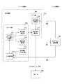
図7は、本発明の実施の形態における再生機器710の構成例を示す図である。このシステム構成例では、再生機器710とテレビジョン受像機器720とが上述のインターフェースによって接続されており、再生機器710がソース機器として動作し、テレビジョン受像機器720がシンク機器として動作する。信号線701はTMDSチャンネル310乃至330に対応し、信号線703はディスプレイデータチャンネル350に対応し、信号線708はリザーブライン362およびHPDライン363に対応する。また、再生機器710には、アナログ信号線709を介してスピーカ750が接続されている。
FIG. 7 is a diagram illustrating a configuration example of the
再生機器710は、記録媒体に記録されている映像信号および音声信号を再生するプレーヤ部730と、音声信号を増幅するアンプ部740とから構成される。プレーヤ部730は、記録媒体アクセス部711と、入力選択部712と、トランスポート信号処理部713と、映像信号復号部714と、音声信号復号部715とを備えている。また、アンプ部740は、遅延情報取得部716と、音声信号遅延部717とを備えている。
The
記録媒体アクセス部711は、記録媒体から映像信号および音声信号を含む信号を読み出すものである。ここでは、記録媒体としてブルーレイディスク(Blu-ray Disc(登録商標):BD)を想定する。ブルーレイディスクにはMPEG(Moving Picture Expert Group)−2のトランスポートストリーム(TS:Transport Stream)方式による信号(トランスポート信号)が記録されており、記録媒体アクセス部711はこのトランスポート信号を読み出して入力選択部712に供給する。
The recording
入力選択部712は、テレビジョン受像機器720から信号線708を介して供給されたトランスポート信号と記録媒体アクセス部711から供給されたトランスポート信号とのうち、何れか一方を選択してトランスポート信号処理部713に供給するものである。
The
トランスポート信号処理部713は、入力選択部712によって供給されたトランスポート信号から、符号化映像信号および符号化音声信号を分離するものである。MPEG−2のトランスポートストリーム方式では、映像信号や音声信号などが符号化されてTSパケットとして伝送される。すなわち、トランスポート信号処理部713は、TSパケットから映像信号および音声信号のそれぞれの符号化されたエレメンタリーストリーム(ES:Elementary Stream)を生成する。
The transport
映像信号復号部714は、トランスポート信号処理部713によって分離された符号化映像信号を復号するデコーダである。この映像信号復号部714によって復号された映像信号は、信号線701を介してテレビジョン受像機器720に伝送される。
The video
音声信号復号部715は、トランスポート信号処理部713によって分離された符号化音声信号を復号するデコーダである。この音声信号復号部715によって復号された音声信号は、音声信号遅延部717に供給される。
The audio
遅延情報取得部716は、テレビジョン受像機器720において映像信号の処理に要する時間(映像処理時間)を、テレビジョン受像機器720から信号線703を介して、遅延情報として取得するものである。HDMI規格では、映像信号や音声信号の処理に要する時間は、E−EDID(Enhanced Extended Display Identification Data)データ構造の一部としてシンク機器に保持され、ディスプレイデータチャンネル(DDC)を介してシンク機器からソース機器に供給される。但し、他の実施の形態として、イーサネット信号の伝送路(リザーブライン362およびHPDライン363)を用いて映像処理時間を取得してもよい。
The delay
音声信号遅延部717は、遅延情報取得部716によって取得された遅延情報(映像処理時間)に基づいて、音声信号復号部715から供給された音声信号を遅延させるものである。この遅延された音声信号は、アナログ信号として増幅されて、アナログ信号線709を介してスピーカ750に出力される。
The audio
スピーカ750は、音声信号遅延部717から出力された音声信号を音声として出力する。
The
図8は、本発明の実施の形態におけるテレビジョン受像機器720の構成例を示す図である。再生機器710とテレビジョン受像機器720との間の接続関係は、図7の例と同様である。但し、CECライン361に対応する信号線704が加えられている。テレビジョン受像機器720は、遅延情報保持部721と、接続機器情報管理部722と、チューナ723と、トランスポート信号切替部724と、トランスポート信号処理部725と、映像信号復号部726と、表示制御部727と、表示部728とを備える。
FIG. 8 is a diagram illustrating a configuration example of the
遅延情報保持部721は、テレビジョン受像機器720の特性情報の一つとして、テレビジョン受像機器720において映像信号や音声信号の処理に要する時間を保持するものである。この遅延情報保持部721は、例えば、EEPROM(Electronically Erasable and Programmable Read Only Memory)により実現される。HDMI規格では、映像信号や音声信号の処理に要する時間は、上述のように、E−EDIDデータ構造の一部としてシンク機器に保持され、ディスプレイデータチャンネル(DDC)を介してシンク機器からソース機器に供給される。但し、他の実施の形態として、イーサネット信号の伝送路(リザーブライン362およびHPDライン363)を用いて映像処理時間を伝送してもよい。
The delay
接続機器情報管理部722は、テレビジョン受像機器720に直接的または間接的に接続されてAVシステムを構成する各機器に関する情報を管理するものである。各機器に関する情報とは、例えば、特定の符号化信号を復号するデコーダを有しているか否かなどの情報が想定される。この例では、信号線704を介して再生機器710と接続して、再生機器710に関する情報を取得するものとしている。HDMI規格では、CECライン361を介して他の機器の存在が検出され、各機器における管理が行われる。
The connected device
チューナ723は、放送信号を受信して選局するものである。デジタル放送の場合、MPEG−2のトランスポートストリーム(TS)方式による信号(トランスポート信号)が放送信号として取得されるのが一般的である。
The
トランスポート信号切替部724は、チューナ723によって取得されたトランスポート信号を、トランスポート信号処理部725または再生機器710の何れか一方に切り替えて出力するものである。この切替えを行う際、トランスポート信号切替部724は、接続機器情報管理部722において管理される情報に基づいて何れに出力するかを判断することができる。例えば、放送信号を復号するデコーダが他の機器において利用可能であれば、その機器に復号処理を依頼するようにしてもよい。また、この切替えについては、接続機器情報管理部722において管理される情報に基づいて自動的に行う他、ユーザから指示に基づいて何れかの機器に復号させるようにしてもよい。
The transport
トランスポート信号処理部725は、トランスポート信号切替部724によって出力されたトランスポート信号から、符号化映像信号および符号化音声信号を分離するものである。このトランスポート信号処理部725の処理内容はトランスポート信号処理部713と同様である。
The transport
映像信号復号部726は、トランスポート信号処理部725によって分離された符号化映像信号を復号するデコーダである。この映像信号復号部726の処理内容は映像信号復号部714と同様である。
The video
表示制御部727は、映像信号復号部726によって復号された映像信号または再生機器710によって復号された映像信号の何れか一方を選択して、表示部728に表示させるよう出力するものである。この選択の際、表示制御部727は、接続機器情報管理部722において管理される情報に基づいて何れを選択するかを判断することができる。例えば、放送信号を復号するデコーダが他の機器において利用可能であれば、その機器によって復号された映像信号を選択するようにしてもよい。また、この選択については、接続機器情報管理部722において管理される情報に基づいて自動的に行う他、ユーザから指示に基づいて何れかの機器によって復号された映像信号を選択させるようにしてもよい。
The
表示部728は、表示制御部727から出力された映像信号を表示するものであり、例えば、LCD(Liquid Crystal Display)などにより実現される。
The
図9は、本発明の実施の形態における遅延情報保持部721に保持されるデータ構造の一例を示す図である。このデータ構造は、HDMI規格のVSDB(Vendor-Specific Data Block)を想定したものであり、ベンダー用タグコードと、ブロック長と、ライセンサー識別子と、物理アドレスと、拡張情報と、ビデオ遅延量と、オーディオ遅延量と、インターレース時ビデオ遅延量と、インターレース時オーディオ遅延量とが含まれている。
FIG. 9 is a diagram showing an example of a data structure held in the delay
ベンダー用タグコードは、このデータ構造を示す番号を保持する3ビットの領域であり、「3」を示す。ブロック長は、このデータ構造のバイト数(N)を保持する5ビットの領域である。ライセンサー識別子は、HDMI規格の組織に付与された識別子を保持する3バイトの領域である。物理アドレスは、CECライン361により用いられるソース機器の物理アドレスを保持する2バイトの領域である。拡張情報は、拡張機能のサポートに関する情報を保持する3バイトの領域である。なお、この拡張情報には、以下の遅延量の有効ビットが含まれる。
The vendor tag code is a 3-bit area that holds a number indicating the data structure, and indicates “3”. The block length is a 5-bit area that holds the number of bytes (N) of this data structure. The licensor identifier is a 3-byte area that holds an identifier assigned to an HDMI standard organization. The physical address is a 2-byte area that holds the physical address of the source device used by the
ビデオ遅延量は、映像信号がプログレッシブ形式である場合に、テレビジョン受像機器720において映像信号を受けてから実際に映像が表示されるまでに要する時間(映像処理時間)を保持する1バイトの領域である。オーディオ遅延量は、映像信号がプログレッシブ形式である場合に、その映像信号に対応する音声信号をテレビジョン受像機器720において受けてから実際に音声が出力されるまでに要する時間を保持する1バイトの領域である。インターレース時ビデオ遅延量は、映像信号がインターレース形式である場合に、テレビジョン受像機器720において映像信号を受けてから実際に映像が表示されるまでに要する時間を保持する1バイトの領域である。インターレース時オーディオ遅延量は、映像信号がインターレース形式である場合に、その映像信号に対応する音声信号をテレビジョン受像機器720において受けてから実際に音声が出力されるまでに要する時間を保持する1バイトの領域である。
The video delay amount is a 1-byte area that holds the time (video processing time) required from when the video signal is received by the
なお、インターレース時オーディオ遅延量に続く領域は予約領域であり、ブロック長(Nバイト)まではこのデータ構造の領域である。 The area following the interlaced audio delay amount is a reserved area, and the area up to the block length (N bytes) is this data structure.
ソース機器である再生機器710は、遅延情報取得部716によって、このデータ構造におけるビデオ遅延量またはインターレース時ビデオ遅延量を遅延情報として取得する。すなわち、映像信号がプログレッシブ形式である場合にはビデオ遅延量が遅延情報となり、映像信号がインターレース形式である場合にはインターレース時ビデオ遅延量が遅延情報となる。音声信号遅延部717は、このように取得された遅延情報から、再生機器710における音声信号の処理時間(音声処理時間)を差し引いた時間分、音声信号復号部715から供給された音声信号を遅延させる。これにより、テレビジョン受像機器720において表示される映像とスピーカ750から出力される音声とが同期して、リップシンクが担保される。
The
図10は、本発明の実施の形態における再生機器710の処理手順の一例を示す図である。同図において、右側がプレーヤ部730における処理手順であり、左側がアンプ部740における処理手順である。ここでは、入力選択部712において、テレビジョン受像機器720から出力されたトランスポート信号が選択される場合を想定している。
FIG. 10 is a diagram illustrating an example of a processing procedure of the
トランスポート信号処理部713は、テレビジョン受像機器720から出力されたトランスポート信号を、入力選択部712を介して受信すると(ステップS911)、そのトランスポート信号から映像信号と音声信号とを分離する(ステップS912)。映像信号復号部714は、分離された映像信号を復号してテレビジョン受像機器720に伝送する(ステップS913)。また、音声信号復号部715は分離された音声信号を復号して音声信号遅延部717に供給する(ステップS914)。
When the transport
遅延情報取得部716は、信号線703(DDC)を介してテレビジョン受像機器720の遅延情報を受信する(ステップS921)。音声信号遅延部717は、取得された遅延情報から、再生機器710における音声処理時間を差し引いた時間を遅延量として算出する(ステップS923)。そして、音声信号遅延部717は、音声信号復号部715から供給された音声信号を受けて(ステップS924)、遅延量に従って音声信号を遅延させて(ステップS925)、スピーカ750に出力する(ステップS926)。
The delay
図11は、本発明の実施の形態におけるテレビジョン受像機器720の処理手順の一例を示す図である。
FIG. 11 is a diagram illustrating an example of a processing procedure of the
チューナ723がトランスポート信号を含む放送信号を選局すると(ステップS931)、トランスポート信号切替部724は、そのトランスポート信号をテレビジョン受像機器720内で復号すべきか否かを判断する(ステップS932)。その際、トランスポート信号切替部724は、接続機器情報管理部722において管理される情報に基づいて判断してもよく、また、ユーザからの指示に従ってもよい。
When the
テレビジョン受像機器720内で復号すると判断された場合(ステップS932)、トランスポート信号処理部725によってトランスポート信号から映像信号が分離され、その分離された映像信号が映像信号復号部726によって復号される(ステップS933)。
When it is determined to be decoded in the television receiver 720 (step S932), the video signal is separated from the transport signal by the transport
一方、再生機器710に復号依頼をすると判断された場合(ステップS932)、トランスポート信号切替部724は、放送信号に含まれるトランスポート信号を再生機器710に信号線708を介して出力する(ステップS936)。これに先立って、遅延情報保持部721に保持された遅延情報が信号線703(DDC)を介して再生機器710にあらかじめ出力されているものとする(ステップS934)。表示制御部727は、再生機器710によって復号された映像信号を受信する(ステップS937)。
On the other hand, when it is determined that the
表示制御部727は、映像信号復号部726によって復号された映像信号または再生機器710によって復号された映像信号の何れか一方を選択して、表示部728に表示させる(ステップS938)。
The
なお、上述の例では遅延情報を伝送する際、HDMI規格のディスプレイデータチャンネル350を用いることを想定したが、リザーブライン362およびHPDライン363を用いたイーサネット信号として遅延情報を伝送するようにしてもよい。
In the above example, it is assumed that the HDMI standard
次に、上述のインターフェースによってHDMI拡張機種を接続した場合の他のシステム構成例について説明する。 Next, another system configuration example when the HDMI extended model is connected through the above-described interface will be described.
図12は、本発明の実施の形態における他のシステム構成例を示す図である。この構成例では、PVR(Personal Video Recorder:ハードディスクドライブレコーダ)810と、STB(セットトップボックス)820と、D−VHS(Data Video Home System)再生機器830と、AVアンプ840と、DVD(Digital Versatile Disk)再生機器860と、テレビジョン受像機器870とが上述のインターフェースにより接続されている。この図において、矢印の元がソース機器を示し、矢印の先がシンク機器を示している。また、AVアンプ840にはスピーカ850がアナログ信号線により接続されている。
FIG. 12 is a diagram showing another system configuration example according to the embodiment of the present invention. In this configuration example, a PVR (Personal Video Recorder) 810, an STB (Set Top Box) 820, a D-VHS (Data Video Home System)
通常のHDMIケーブルの場合、映像信号および音声信号はソース機器からシンク機器に対して伝送されるため、この接続例ではDVD再生機器860によって再生された信号をテレビジョン受像機器870から出力することは可能であるが、音声信号をスピーカ850から出力することはできない。これに対して、図3乃至6において説明したインターフェースによれば、双方向に信号を伝送することができるため、テレビジョン受像機器870からAVアンプ840に向けて音声信号を伝送することができる。
In the case of a normal HDMI cable, the video signal and the audio signal are transmitted from the source device to the sink device. Therefore, in this connection example, the signal reproduced by the
図13は、本発明の実施の形態における他のシステム構成例による音声信号の経路を示す図である。 FIG. 13 is a diagram showing a path of an audio signal according to another system configuration example in the embodiment of the present invention.
この例では、STB820に復号を依頼し、スピーカ850から音声を出力することを想定する。DVD再生機器860によってDVDから読み出された符号化映像信号および符号化音声信号は、イーサネット信号としてリザーブライン362およびHPDライン363によりSTB820に伝送される。
In this example, it is assumed that decoding is requested to the
STB820は、図7により説明したプレーヤ部730と同様の構成により、符号化映像信号および符号化音声信号を復号する。STB820において復号された映像信号および音声信号は、TMDSチャンネル310乃至330によりAVアンプ840に伝送される。
The
AVアンプ840は、映像信号をTMDSチャンネル310乃至330によりテレビジョン受像機器870へ伝送するとともに、図7により説明したアンプ部740と同様の構成により音声信号を遅延させてスピーカ850に出力する。
The
このように、本発明の実施の形態によれば、HDMI規格のように片方向伝送を基本とするインターフェースを用いるシステムにおいて、機器の接続態様に関わらず柔軟な再生を行うことができる。また、その際、再生される映像と音声との間の同期(リップシンク)を担保することができる。 As described above, according to the embodiment of the present invention, in a system using an interface based on one-way transmission as in the HDMI standard, flexible playback can be performed regardless of the connection mode of devices. At that time, synchronization (lip sync) between the reproduced video and audio can be ensured.
また、本発明の実施の形態によれば、復号処理を他の機器に依頼することができるため、自機器におけるデコーダの数やバージョンの制約を受けることなく柔軟な再生を行うことができる。例えば、テレビジョン受像機器870におけるデコーダの数が1つの場合でも、一つの放送信号については自機器において復号し、もう一つの放送信号については他の機器に復号を依頼することにより、図14の画面600のように複数の放送の画面表示610および620を行うことができる。すなわち、映像復号部および音声復号部の数をn(nは0以上の整数)とした場合、nより多い映像または音声を出力することができる。
Further, according to the embodiment of the present invention, since decoding processing can be requested to another device, flexible reproduction can be performed without being restricted by the number and version of decoders in the device itself. For example, even when the number of decoders in the
次に、本発明の実施の形態における変形例について説明する。 Next, a modification of the embodiment of the present invention will be described.
図15は、本発明の実施の形態におけるソース機器100およびシンク機器200の内部構成の変形例について示す図である。ここでは、図3と同様に、リザーブライン362およびHPDライン363に関する構成を示している。図3の構成例と比べて、ソース機器100にSPDIF(Sony Philips Digital InterFace)受信回路170を備え、シンク機器200にSPDIF送信回路270を備えている。
FIG. 15 is a diagram showing a modified example of the internal configuration of the
SPDIF受信回路170およびSPDIF送信回路270は、SPDIF規格に準拠した単一方向通信を行うものである。ここで、SPDIF規格とは、デジタルオーディオ信号をリアルタイムに伝送するためのインターフェース規格であり、IEC(International Electrotechnical Commission:国際電気標準会議)において「IEC 60958」として規格化されている。このSPDIF規格において伝送されるSPDIF信号は、バイフェーズマーク変調されるため、その信号中にクロック成分を含んでいる。なお、これらSPDIF受信回路170およびSPDIF送信回路270は、従来技術により実現される。
The
図16は、本発明の実施の形態におけるソース側送受信回路140およびシンク側送受信回路250の構成の変形例を示す図である。
FIG. 16 is a diagram showing a modified example of the configuration of the source-
図16(a)に示すように、シンク側送受信回路250は、増幅器510、520、530および550と、インバータ541と、加算器542、571および572とを備えている。すなわち、図4(a)の構成例と比べて、加算器571および572が追加された構成となっている。
As shown in FIG. 16A, the sink-side transmission /
加算器571は、SPDIF送信回路270から信号線561を介して供給される信号と増幅器520の正極出力とを加算する回路である。加算器572は、加算器571は、SPDIF送信回路270から信号線561を介して供給される信号と増幅器520の負極出力とを加算する回路である。
The
すなわち、増幅器550から出力されるイーサネット信号が差動信号であるのに対して、加算器571および572により重畳されるSPDIF信号は同相信号である。これにより、イーサネット信号およびSPDIF信号の両者は、同じ一対の信号線(リザーブライン362およびHPDライン363)によって伝送することが可能となる。
That is, the Ethernet signal output from the
図16(b)に示すように、ソース側送受信回路140は、増幅器410、420、430および450と、インバータ441と、加算器442および460とを備えている。すなわち、図4(b)の構成例と比べて、加算器460が追加された構成となっている。
As shown in FIG. 16B, the source-side transmitting / receiving
加算器460は、増幅器420の出力の正極の信号と負極の信号とを加算する回路である。すなわち、リザーブライン362およびHPDライン363によって伝送された信号のうち、差動信号がイーサネット信号として増幅器430によって抽出され、同相信号がSPDIF信号として加算器460によって抽出されるようになっている。この加算器460の出力は、SPDIF受信回路170に供給される。
The
図17は、本発明の実施の形態における再生機器710の構成の変形例を示す図である。この変形例では、図7の構成例に加えて、SPDIF信号を伝送する信号線707および音声信号を伝送する信号線702が追加されている。但し、上述のように、SPDIF信号はイーサネット信号と重畳されて同じ一対の信号線(リザーブライン362およびHPDライン363)によって伝送可能であるため、ケーブルを物理的に追加することなく実現することができる。また、信号線702は、信号線701とともにTMDSチャンネル310乃至330により実現されるため、ケーブルを物理的に追加することなく実現することができる。
FIG. 17 is a diagram showing a modification of the configuration of the
この変形例では、図7の遅延情報取得部716に代えて、遅延時間測定部718を備えている。そして、音声信号復号部715から出力された音声信号を遅延時間測定部718に供給するとともに、信号線702を介してテレビジョン受像機器720にも供給しておく。遅延時間測定部718は、テレビジョン受像機器720から信号線707を介して返送された音声信号と音声信号復号部715から出力された音声信号との間の時間上の差分(ずれ)を映像処理時間として測定する。
In this modification, a delay
この場合、遅延時間測定部718は、テレビジョン受像機器720から返送された音声信号と音声信号復号部715から出力された音声信号との間の相互相関により映像処理時間を求めることができる。また、音声信号として特定のパターンを有する測定用の信号を送って、その測定用信号に対する応答をテレビジョン受像機器720から遅延時間測定部718に返送することにより、その応答時間を映像処理時間として求めてもよい。
In this case, the delay
図18は、本発明の実施の形態におけるテレビジョン受像機器720の構成の変形例を示す図である。再生機器710とテレビジョン受像機器720との間の接続関係は、図17の例と同様である。但し、CECライン361に対応する信号線704が加えられている。
FIG. 18 is a diagram illustrating a modification of the configuration of the
この変形例では、図8の遅延情報保持部721に代えて、音声信号返送部729を備えている。音声信号返送部729は、再生機器710において復号された映像信号が表示部728に表示されるタイミングで、その映像信号に時間的に対応する音声信号を、信号線707を介して再生機器710に返送するものである。映像信号が表示部728に表示されるタイミングは、表示制御部727から音声信号返送部729に通知される。
In this modification, an audio
図19は、本発明の実施の形態における再生機器710の処理手順の変形例を示す図である。同図において、右側が図17のプレーヤ部730における処理手順であり、左側が図17のアンプ部740における処理手順である。したがって、同図右側の処理手順は、図10の右側の処理手順と同じになっている。但し、ステップS914において復号された音声信号がテレビジョン受像機器720に伝送される点は異なっている。
FIG. 19 is a diagram showing a modification of the processing procedure of the
遅延時間測定部718は、信号線707を介してテレビジョン受像機器720から返送された音声信号を受信して(ステップS941)、返送された音声信号と音声信号復号部715から出力された音声信号との間の時間上の差分を遅延時間(映像処理時間)として測定する(ステップS942)。音声信号遅延部717は、取得された遅延時間から、再生機器710における音声処理時間を差し引いた時間を遅延量として算出する(ステップS943)。そして、音声信号遅延部717は、音声信号復号部715から供給された音声信号を受けて(ステップS944)、遅延量に従って音声信号を遅延させて(ステップS945)、スピーカ750に出力する(ステップS946)。
The delay
図20は、本発明の実施の形態におけるテレビジョン受像機器720の処理手順の変形例を示す図である。同図は、図18の構成例を想定したものである。
FIG. 20 is a diagram showing a modification of the processing procedure of the
チューナ723がトランスポート信号を含む放送信号を選局すると(ステップS951)、トランスポート信号切替部724は、そのトランスポート信号をテレビジョン受像機器720内で復号すべきか否かを判断する(ステップS952)。テレビジョン受像機器720内で復号すると判断された場合、トランスポート信号処理部725によってトランスポート信号から映像信号が分離され、その分離された映像信号が映像信号復号部726によって復号される(ステップS953)。これらの処理は図11と同様である。
When the
一方、再生機器710に復号依頼をすると判断された場合(ステップS952)、トランスポート信号切替部724は、放送信号に含まれるトランスポート信号を再生機器710に信号線708を介して出力する(ステップS956)。これに先立って、音声信号返送部729は、再生機器710から信号線702を介して音声信号を受信して(ステップS954)、再生機器710において復号された映像信号が表示部728に表示されるタイミングで、その映像信号に時間的に対応する音声信号を、信号線707を介して再生機器710に返送しているものとする(ステップS955)。表示制御部727は、再生機器710によって復号された映像信号を受信する(ステップS957)。
On the other hand, when it is determined that the
この変形例によれば、テレビジョン受像機器720において遅延情報を保持しておくことなく、実際に遅延時間を測定することにより、再生される映像と音声との間の同期を担保することができる。
According to this modification, synchronization between the reproduced video and audio can be ensured by actually measuring the delay time without retaining the delay information in the
なお、本発明の実施の形態は本発明を具現化するための一例を示したものであり、以下に示すように特許請求の範囲における発明特定事項とそれぞれ対応関係を有するが、これに限定されるものではなく本発明の要旨を逸脱しない範囲において種々の変形を施すことができる。 The embodiment of the present invention is an example for embodying the present invention, and has a corresponding relationship with the invention-specific matters in the claims as described below, but is not limited thereto. However, various modifications can be made without departing from the scope of the present invention.
なお、本発明の実施の形態において説明した処理手順は、これら一連の手順を有する方法として捉えてもよく、また、これら一連の手順をコンピュータに実行させるためのプログラム乃至そのプログラムを記憶する記録媒体として捉えてもよい。 The processing procedure described in the embodiment of the present invention may be regarded as a method having a series of these procedures, and a program for causing a computer to execute these series of procedures or a recording medium storing the program May be taken as
100 ソース機器
110 シンク機種検出回路
120 プラグ接続検出回路
140 ソース側送受信回路
160 イーサネット送受信回路
170 SPDIF受信回路
200 シンク機器
210 ソース機種検出回路
220 プラグ接続伝達回路
250 シンク側送受信回路
260 イーサネット送受信回路
270 SPDIF送信回路
300 HDMIケーブル
310、320、330 TMDSチャンネル
340 TMDSクロックチャンネル
350 ディスプレイデータチャンネル(DDC)
361 CECライン
362 リザーブライン
363 HPDライン
710 再生機器
711 記録媒体アクセス部
712 入力選択部
713、725 トランスポート信号処理部
714、726 映像信号復号部
715 音声信号復号部
716 遅延情報取得部
717 音声信号遅延部
718 遅延時間測定部
720、870 テレビジョン受像機器
721 遅延情報保持部
722 接続機器情報管理部
723 チューナ
724 トランスポート信号切替部
727 表示制御部
728 表示部
729 音声信号返送部
730 プレーヤ部
740 アンプ部
750、850 スピーカ
810 PVR(ハードディスクドライブレコーダ)
820 STB(セットトップボックス)
830 D−VHS再生機器
840 AVアンプ
860 DVD再生機器
DESCRIPTION OF
361
820 STB (Set Top Box)
830 D-
Claims (8)
前記符号化映像信号を復号して当該復号された映像信号を映像出力装置に出力する映像信号復号手段と、
前記符号化音声信号を復号して当該復号された音声信号を前記映像出力装置に出力する音声信号復号手段と、
前記映像出力装置から返送された音声信号と前記音声信号復号手段によって復号された前記音声信号との時間上の差分を映像処理時間として測定して当該映像処理時間からこの再生装置における音声信号処理時間を差し引いた時間分、前記音声信号を遅延させた後に当該音声信号を音声出力装置に供給する音声信号処理手段と
を具備する再生装置。 Separating means for receiving a stream signal including an encoded video signal and an encoded audio signal from a stream generation device and separating the encoded video signal and the encoded audio signal from the stream signal;
A video signal decoding means for outputting a video signal the decoded decodes the encoded video signal to the video output device,
Audio signal decoding means for decoding the encoded audio signal and outputting the decoded audio signal to the video output device ;
The time difference between the audio signal returned from the video output device and the audio signal decoded by the audio signal decoding means is measured as the video processing time, and the audio signal processing time in the playback device is calculated from the video processing time. time obtained by subtracting the, you and a sound signal processing means for providing the audio output device the audio signal after delaying the audio signal playback apparatus.
前記データ信号線路を介して受信した同相信号から前記返送された音声信号を抽出する第2の受信手段と
をさらに具備する請求項1記載の再生装置。 First receiving means for extracting the stream signal from a differential signal received via a data signal line connected to the video output device;
The data signal line reproducing apparatus of the second receiving means and further to that請 Motomeko 1, wherein comprises a to extract the audio signal the return from the in-phase signal received via.
前記ストリーム信号を生成するストリーム信号生成手段と、
前記再生装置との間の接続状態に関する接続情報を管理する接続情報管理手段と、
前記接続情報に基づいて前記ストリーム信号を復号する前記再生装置が接続されているか否かを判断して前記再生装置が接続されている場合には当該再生装置に前記ストリーム信号を出力するよう切り替えるストリーム信号切替手段と、
前記再生装置によって復号された映像信号を受信して表示手段に表示させる表示制御手段と、
前記再生装置によって復号された音声信号を受信して、前記再生装置によって復号された映像信号が前記表示手段に表示されるタイミングで前記映像信号に対応する音声信号を前記再生装置に返送する音声信号返送手段と
を具備する表示装置。 Separating means for receiving a stream signal including an encoded video signal and an encoded audio signal from a display device and separating the encoded video signal and the encoded audio signal from the stream signal; and decoding the encoded video signal Video signal decoding means for outputting the decoded video signal to the display device, audio signal decoding means for decoding the encoded audio signal and outputting the decoded audio signal to the display device, The time difference between the audio signal returned from the display device and the audio signal decoded by the audio signal decoding means is measured as the video processing time, and the audio signal processing time in the playback device is subtracted from the video processing time. A table that is connectable to a playback device comprising audio signal processing means for delaying the audio signal by an amount of time and supplying the audio signal to an audio output device An apparatus,
A stream signal generating means for generating the stream signal,
Connection information management means for managing connection information regarding a connection state with the playback device;
A stream that determines whether or not the playback device that decodes the stream signal is connected based on the connection information and switches the output of the stream signal to the playback device when the playback device is connected Signal switching means;
Display control means for receiving the video signal decoded by the playback device and displaying it on the display means;
An audio signal that receives an audio signal decoded by the playback device and returns an audio signal corresponding to the video signal to the playback device at a timing when the video signal decoded by the playback device is displayed on the display means Viewing device you provided with return means <br/>.
前記音声信号返送手段により返送される音声信号を同相信号として前記データ信号線路に重畳して前記再生装置に送信する第2の送信手段と
をさらに具備する請求項4記載の表示装置。 A first transmission means for transmitting the stream signal via a connected data signal line between the reproduction apparatus to the reproduction apparatus as a differential signal,
The display device of the second transmission means and further to that請 Motomeko 4 wherein comprising a transmitting voice signal to said reproducing apparatus is superimposed on the data signal line as an in-phase signal sent back by the audio signal returning means.
前記ストリーム信号から前記符号化映像信号と前記符号化音声信号とを分離する分離手順と、
前記符号化映像信号を復号して当該復号された映像信号を映像出力装置に出力する映像信号復号手順と、
前記符号化音声信号を復号して当該復号された音声信号を前記映像出力装置に出力する音声信号復号手順と、
前記映像出力装置から返送された音声信号と前記音声信号復号手順において復号された前記音声信号との時間上の差分を映像処理時間として測定して当該映像処理時間から再生装置における音声信号処理時間を差し引いた時間分、前記音声信号を遅延させた後に当該音声信号を音声出力装置に供給する音声信号遅延手順と
を具備する再生方法。 A reception procedure for receiving a stream signal including an encoded video signal and an encoded audio signal from the stream generation device;
A separation procedure for separating the encoded video signal and the encoded audio signal from the stream signal;
A video signal decoding procedure that outputs a video signal corresponding decoded by decoding the encoded video signal to the video output device,
An audio signal decoding procedure for decoding the encoded audio signal and outputting the decoded audio signal to the video output device ;
The time difference between the audio signal returned from the video output device and the audio signal decoded in the audio signal decoding procedure is measured as the video processing time, and the audio signal processing time in the playback device is calculated from the video processing time. subtracted time duration, the audio signal delay steps and Pla how to include a supplies the audio signal after delaying the audio signal to the audio output device.
前記ストリーム信号を生成するストリーム信号生成手順と、
前記再生装置との間の接続状態に関する接続情報に基づいて前記ストリーム信号を復号する前記再生装置が接続されているか否かを判断する判断手順と、
前記再生装置が接続されている場合には前記表示制御手段における前記映像信号の処理に要する時間を映像処理時間として前記再生装置に供給する映像処理時間供給手順と、
前記再生装置が接続されている場合には当該再生装置に前記ストリーム信号を出力するよう切り替えるストリーム信号切替手順と、
前記再生装置によって復号された映像信号を受信して表示手段に表示させる表示制御手順と、
前記再生装置によって復号された音声信号を受信して、前記再生装置によって復号された映像信号が前記表示手段に表示されるタイミングで前記映像信号に対応する音声信号を前記再生装置に返送する音声信号返送手順と
を具備する表示方法。 Separating means for receiving a stream signal including an encoded video signal and an encoded audio signal from a display device and separating the encoded video signal and the encoded audio signal from the stream signal; and decoding the encoded video signal Video signal decoding means for outputting the decoded video signal to the display device, audio signal decoding means for decoding the encoded audio signal and outputting the decoded audio signal to the display device, The time difference between the audio signal returned from the display device and the audio signal decoded by the audio signal decoding means is measured as the video processing time, and the audio signal processing time in the playback device is subtracted from the video processing time. time duration, the table can be connected with the reproducing apparatus and an audio signal processing means for providing the audio output device the audio signal after delaying the audio signal In the device,
A stream signal generation step of generating the stream signal,
A determination procedure for determining whether or not the playback device that decodes the stream signal is connected based on connection information related to a connection state with the playback device ;
When the playback device is connected, a video processing time supply procedure for supplying the playback device with a time required for processing the video signal in the display control means as a video processing time;
A stream signal switching procedure for switching the playback apparatus to output the stream signal when the playback apparatus is connected;
A display control procedure for receiving and displaying the video signal decoded by the reproduction apparatus in Viewing means,
An audio signal that receives an audio signal decoded by the playback device and returns an audio signal corresponding to the video signal to the playback device at a timing when the video signal decoded by the playback device is displayed on the display means Table How to Display you provided with return procedure <br/>.
Priority Applications (7)
| Application Number | Priority Date | Filing Date | Title |
|---|---|---|---|
| JP2007303186A JP5050807B2 (en) | 2007-11-22 | 2007-11-22 | REPRODUCTION DEVICE, DISPLAY DEVICE, REPRODUCTION METHOD, AND DISPLAY METHOD |
| PCT/JP2008/070863 WO2009066634A1 (en) | 2007-11-22 | 2008-11-17 | Reproduction apparatus, display apparatus, reproduction method, and display method |
| EP08852993.8A EP2211545B1 (en) | 2007-11-22 | 2008-11-17 | Reproduction apparatus, display apparatus, reproduction method, and display method |
| KR1020097013863A KR101523390B1 (en) | 2007-11-22 | 2008-11-17 | Playback apparatus, display apparatus, playback method, and display method |
| CN2008800028118A CN101589621B (en) | 2007-11-22 | 2008-11-17 | Reproduction apparatus, display apparatus, reproduction method, and display method |
| US12/449,080 US8364004B2 (en) | 2007-11-22 | 2008-11-17 | Reproducing apparatus, display apparatus, reproducing method, and display method |
| US13/363,649 US9247289B2 (en) | 2007-11-22 | 2012-02-01 | Reproducing apparatus, display apparatus, reproducing method, and display method |
Applications Claiming Priority (1)
| Application Number | Priority Date | Filing Date | Title |
|---|---|---|---|
| JP2007303186A JP5050807B2 (en) | 2007-11-22 | 2007-11-22 | REPRODUCTION DEVICE, DISPLAY DEVICE, REPRODUCTION METHOD, AND DISPLAY METHOD |
Publications (2)
| Publication Number | Publication Date |
|---|---|
| JP2009130607A JP2009130607A (en) | 2009-06-11 |
| JP5050807B2 true JP5050807B2 (en) | 2012-10-17 |
Family
ID=40667456
Family Applications (1)
| Application Number | Title | Priority Date | Filing Date |
|---|---|---|---|
| JP2007303186A Expired - Fee Related JP5050807B2 (en) | 2007-11-22 | 2007-11-22 | REPRODUCTION DEVICE, DISPLAY DEVICE, REPRODUCTION METHOD, AND DISPLAY METHOD |
Country Status (6)
| Country | Link |
|---|---|
| US (2) | US8364004B2 (en) |
| EP (1) | EP2211545B1 (en) |
| JP (1) | JP5050807B2 (en) |
| KR (1) | KR101523390B1 (en) |
| CN (1) | CN101589621B (en) |
| WO (1) | WO2009066634A1 (en) |
Families Citing this family (23)
| Publication number | Priority date | Publication date | Assignee | Title |
|---|---|---|---|---|
| WO2006118106A1 (en) | 2005-04-28 | 2006-11-09 | Matsushita Electric Industrial Co., Ltd. | Lip-sync correcting device and lip-sync correcting method |
| JP5109978B2 (en) | 2006-11-07 | 2012-12-26 | ソニー株式会社 | Electronic device, control information transmitting method and control information receiving method |
| KR101488729B1 (en) * | 2008-05-13 | 2015-02-06 | 삼성전자주식회사 | Digital broadcast transmitting apparatus and receiving apparatus and methods thereof |
| JP2010193247A (en) * | 2009-02-19 | 2010-09-02 | Sanyo Electric Co Ltd | Hdmi apparatus |
| JP5040943B2 (en) * | 2009-03-12 | 2012-10-03 | セイコーエプソン株式会社 | Image / audio supply apparatus, image / audio supply system, image / audio supply method, and program for image / audio supply |
| JP5372643B2 (en) * | 2009-07-29 | 2013-12-18 | 株式会社タムラ製作所 | Delay adjustment system |
| JP2011172156A (en) * | 2010-02-22 | 2011-09-01 | Sony Corp | Content reproduction system, content receiving apparatus, audio reproduction apparatus, content reproduction method and program |
| US8692937B2 (en) * | 2010-02-25 | 2014-04-08 | Silicon Image, Inc. | Video frame synchronization |
| JP5754080B2 (en) * | 2010-05-21 | 2015-07-22 | ソニー株式会社 | Data transmitting apparatus, data receiving apparatus, data transmitting method and data receiving method |
| JP2012119924A (en) * | 2010-11-30 | 2012-06-21 | Toshiba Corp | Video display apparatus, video display method, audio reproduction apparatus, audio reproduction method, and video/audio synchronous control system |
| JP2012191583A (en) * | 2011-03-14 | 2012-10-04 | Yamaha Corp | Signal output device |
| US9537644B2 (en) * | 2012-02-23 | 2017-01-03 | Lattice Semiconductor Corporation | Transmitting multiple differential signals over a reduced number of physical channels |
| JP5969779B2 (en) * | 2012-03-09 | 2016-08-17 | ローム株式会社 | Audio output circuit, electronic device using the same, and audio integrated circuit |
| US9230505B2 (en) | 2013-02-25 | 2016-01-05 | Lattice Semiconductor Corporation | Apparatus, system and method for providing clock and data signaling |
| KR102201617B1 (en) * | 2014-01-07 | 2021-01-12 | 삼성전자 주식회사 | Av device and control method thereof |
| US9871516B2 (en) | 2014-06-04 | 2018-01-16 | Lattice Semiconductor Corporation | Transmitting apparatus with source termination |
| KR20160022096A (en) * | 2014-08-19 | 2016-02-29 | 삼성전자주식회사 | apparatus and method for checking that a main controller and a sub unit are connected |
| WO2016060474A1 (en) * | 2014-10-14 | 2016-04-21 | 엘지전자(주) | Method and apparatus for transmitting and receiving data using hdmi |
| JP6956354B2 (en) * | 2018-08-30 | 2021-11-02 | パナソニックIpマネジメント株式会社 | Video signal output device, control method, and program |
| CN109587546B (en) * | 2018-11-27 | 2020-09-22 | Oppo广东移动通信有限公司 | Video processing method, apparatus, electronic device and computer readable medium |
| US11533534B2 (en) * | 2019-02-20 | 2022-12-20 | Huawei Technologies Co., Ltd. | Techniques for enabling ultra-high definition alliance specified reference mode (UHDA-SRM) |
| CN112449278B (en) * | 2019-09-03 | 2022-04-22 | 深圳Tcl数字技术有限公司 | Method, device and equipment for automatically calibrating delay output sound and storage medium |
| US11323766B2 (en) * | 2019-10-03 | 2022-05-03 | Dolby International Ab | Method and device for providing audio/video content to a rendering device |
Family Cites Families (13)
| Publication number | Priority date | Publication date | Assignee | Title |
|---|---|---|---|---|
| JPH0969987A (en) * | 1995-08-30 | 1997-03-11 | Hitachi Ltd | Television signal receiver |
| JP2001028748A (en) * | 1999-07-12 | 2001-01-30 | Sony Corp | Data reproduction transmitter and data reproduction transmission method |
| JP4200410B2 (en) * | 1999-12-06 | 2008-12-24 | ソニー株式会社 | Device selection device and device selection method |
| JP2002176643A (en) * | 2000-12-06 | 2002-06-21 | Hitachi Kokusai Electric Inc | Synchronization recovery system for video/audio in video/ audio decoding processing |
| JP2002344898A (en) * | 2001-05-17 | 2002-11-29 | Pioneer Electronic Corp | Video display device, audio adjusting device, video and audio output device, and method for synchronizing video and audio |
| US20070223874A1 (en) | 2004-04-07 | 2007-09-27 | Koninklijke Philips Electronics, N.V. | Video-Audio Synchronization |
| JP4427733B2 (en) | 2004-07-16 | 2010-03-10 | ソニー株式会社 | VIDEO / AUDIO PROCESSING SYSTEM, AMPLIFIER DEVICE, AND AUDIO DELAY TREATMENT METHOD |
| KR100584615B1 (en) * | 2004-12-15 | 2006-06-01 | 삼성전자주식회사 | Audio / Video Synchronization Auto Adjustment Device and Method |
| KR100766496B1 (en) * | 2005-07-08 | 2007-10-15 | 삼성전자주식회사 | HDM Transmission System |
| US7884836B2 (en) * | 2005-08-30 | 2011-02-08 | Ati Technologies Ulc | Notifying a graphics subsystem of a physical change at a display device |
| JP2007221422A (en) * | 2006-02-16 | 2007-08-30 | Onkyo Corp | Video audio reproducing system, av center constituting the same, and monitor |
| JP4575324B2 (en) | 2006-03-29 | 2010-11-04 | 株式会社東芝 | AV apparatus and control method thereof |
| WO2008056718A1 (en) * | 2006-11-07 | 2008-05-15 | Sony Corporation | Electronic device, content reproducing method, and content decoding method |
-
2007
- 2007-11-22 JP JP2007303186A patent/JP5050807B2/en not_active Expired - Fee Related
-
2008
- 2008-11-17 EP EP08852993.8A patent/EP2211545B1/en not_active Not-in-force
- 2008-11-17 CN CN2008800028118A patent/CN101589621B/en not_active Expired - Fee Related
- 2008-11-17 WO PCT/JP2008/070863 patent/WO2009066634A1/en active Application Filing
- 2008-11-17 US US12/449,080 patent/US8364004B2/en not_active Expired - Fee Related
- 2008-11-17 KR KR1020097013863A patent/KR101523390B1/en active IP Right Grant
-
2012
- 2012-02-01 US US13/363,649 patent/US9247289B2/en not_active Expired - Fee Related
Also Published As
| Publication number | Publication date |
|---|---|
| US20120128319A1 (en) | 2012-05-24 |
| CN101589621A (en) | 2009-11-25 |
| WO2009066634A1 (en) | 2009-05-28 |
| EP2211545A1 (en) | 2010-07-28 |
| EP2211545A4 (en) | 2013-08-28 |
| KR20100094335A (en) | 2010-08-26 |
| US8364004B2 (en) | 2013-01-29 |
| CN101589621B (en) | 2011-09-28 |
| JP2009130607A (en) | 2009-06-11 |
| US9247289B2 (en) | 2016-01-26 |
| KR101523390B1 (en) | 2015-05-27 |
| US20100067877A1 (en) | 2010-03-18 |
| EP2211545B1 (en) | 2018-10-03 |
Similar Documents
| Publication | Publication Date | Title |
|---|---|---|
| JP5050807B2 (en) | REPRODUCTION DEVICE, DISPLAY DEVICE, REPRODUCTION METHOD, AND DISPLAY METHOD | |
| JP5428186B2 (en) | Electronics | |
| JP4434267B2 (en) | Interface circuit | |
| JP5003389B2 (en) | Electronic device and control method in electronic device | |
| JP5223678B2 (en) | Electronic device, content reproduction method, and content decryption method | |
| US20100269137A1 (en) | Transmission device, video signal transmission method for transmission device, reception device, and video signal reception method for reception device | |
| US20110206355A1 (en) | Content reproduction system, content receiving apparatus, sound reproduction apparatus, content reproduction method and program | |
| US20060208929A1 (en) | High definition multimedia interface device and output control method thereof | |
| WO2009093506A1 (en) | Transmission device, reception device, frame rate conversion system, and frame rate conversion method | |
| JP6863282B2 (en) | Receiver and receiving method | |
| KR20100126174A (en) | Transmitter and receiver | |
| WO2009133854A1 (en) | Transmission device, information transmission method, reception device, and information processing method | |
| JP2009284403A (en) | Information processing apparatus, information processing method, program and content receiving device | |
| KR20090074864A (en) | Display device and advertising skip method | |
| JP4596087B2 (en) | Interface circuit | |
| JP5910660B2 (en) | Transmitting apparatus and information processing method | |
| JP5477506B1 (en) | Transmitting apparatus and information processing method | |
| JP5522332B1 (en) | Receiving apparatus and information processing method | |
| JP6669071B2 (en) | Transmitting device, transmitting method, receiving device and receiving method | |
| JP5910661B2 (en) | Receiving apparatus and information processing method | |
| JP4596085B2 (en) | Interface circuit |
Legal Events
| Date | Code | Title | Description |
|---|---|---|---|
| A621 | Written request for application examination |
Free format text: JAPANESE INTERMEDIATE CODE: A621 Effective date: 20101027 |
|
| A131 | Notification of reasons for refusal |
Free format text: JAPANESE INTERMEDIATE CODE: A131 Effective date: 20120501 |
|
| A521 | Request for written amendment filed |
Free format text: JAPANESE INTERMEDIATE CODE: A523 Effective date: 20120604 |
|
| TRDD | Decision of grant or rejection written | ||
| A01 | Written decision to grant a patent or to grant a registration (utility model) |
Free format text: JAPANESE INTERMEDIATE CODE: A01 Effective date: 20120626 |
|
| A01 | Written decision to grant a patent or to grant a registration (utility model) |
Free format text: JAPANESE INTERMEDIATE CODE: A01 |
|
| A61 | First payment of annual fees (during grant procedure) |
Free format text: JAPANESE INTERMEDIATE CODE: A61 Effective date: 20120709 |
|
| R151 | Written notification of patent or utility model registration |
Ref document number: 5050807 Country of ref document: JP Free format text: JAPANESE INTERMEDIATE CODE: R151 |
|
| FPAY | Renewal fee payment (event date is renewal date of database) |
Free format text: PAYMENT UNTIL: 20150803 Year of fee payment: 3 |
|
| R250 | Receipt of annual fees |
Free format text: JAPANESE INTERMEDIATE CODE: R250 |
|
| R250 | Receipt of annual fees |
Free format text: JAPANESE INTERMEDIATE CODE: R250 |
|
| R250 | Receipt of annual fees |
Free format text: JAPANESE INTERMEDIATE CODE: R250 |
|
| R250 | Receipt of annual fees |
Free format text: JAPANESE INTERMEDIATE CODE: R250 |
|
| R250 | Receipt of annual fees |
Free format text: JAPANESE INTERMEDIATE CODE: R250 |
|
| R250 | Receipt of annual fees |
Free format text: JAPANESE INTERMEDIATE CODE: R250 |
|
| LAPS | Cancellation because of no payment of annual fees |