JP5039815B2 - Idle stop vehicle - Google Patents
Idle stop vehicle Download PDFInfo
- Publication number
- JP5039815B2 JP5039815B2 JP2010176097A JP2010176097A JP5039815B2 JP 5039815 B2 JP5039815 B2 JP 5039815B2 JP 2010176097 A JP2010176097 A JP 2010176097A JP 2010176097 A JP2010176097 A JP 2010176097A JP 5039815 B2 JP5039815 B2 JP 5039815B2
- Authority
- JP
- Japan
- Prior art keywords
- idle
- stop
- satisfied
- condition
- idle stop
- Prior art date
- Legal status (The legal status is an assumption and is not a legal conclusion. Google has not performed a legal analysis and makes no representation as to the accuracy of the status listed.)
- Active
Links
- 230000005540 biological transmission Effects 0.000 claims description 96
- 230000007246 mechanism Effects 0.000 description 42
- 238000000034 method Methods 0.000 description 33
- 230000008569 process Effects 0.000 description 31
- 239000003921 oil Substances 0.000 description 28
- 239000000446 fuel Substances 0.000 description 19
- 230000008859 change Effects 0.000 description 10
- 230000000694 effects Effects 0.000 description 9
- 230000035939 shock Effects 0.000 description 8
- XLYOFNOQVPJJNP-UHFFFAOYSA-N water Substances O XLYOFNOQVPJJNP-UHFFFAOYSA-N 0.000 description 7
- 239000012530 fluid Substances 0.000 description 5
- 230000000994 depressogenic effect Effects 0.000 description 2
- 238000010586 diagram Methods 0.000 description 2
- 230000006872 improvement Effects 0.000 description 2
- 230000004044 response Effects 0.000 description 2
- 239000000969 carrier Substances 0.000 description 1
- 230000003111 delayed effect Effects 0.000 description 1
- 239000010720 hydraulic oil Substances 0.000 description 1
- 239000003112 inhibitor Substances 0.000 description 1
- 238000002347 injection Methods 0.000 description 1
- 239000007924 injection Substances 0.000 description 1
- 230000004048 modification Effects 0.000 description 1
- 238000012986 modification Methods 0.000 description 1
- 230000007935 neutral effect Effects 0.000 description 1
- 230000002265 prevention Effects 0.000 description 1
- 230000009467 reduction Effects 0.000 description 1
- 230000001360 synchronised effect Effects 0.000 description 1
Images


Classifications
-
- F—MECHANICAL ENGINEERING; LIGHTING; HEATING; WEAPONS; BLASTING
- F02—COMBUSTION ENGINES; HOT-GAS OR COMBUSTION-PRODUCT ENGINE PLANTS
- F02D—CONTROLLING COMBUSTION ENGINES
- F02D29/00—Controlling engines, such controlling being peculiar to the devices driven thereby, the devices being other than parts or accessories essential to engine operation, e.g. controlling of engines by signals external thereto
- F02D29/02—Controlling engines, such controlling being peculiar to the devices driven thereby, the devices being other than parts or accessories essential to engine operation, e.g. controlling of engines by signals external thereto peculiar to engines driving vehicles; peculiar to engines driving variable pitch propellers
-
- F—MECHANICAL ENGINEERING; LIGHTING; HEATING; WEAPONS; BLASTING
- F02—COMBUSTION ENGINES; HOT-GAS OR COMBUSTION-PRODUCT ENGINE PLANTS
- F02N—STARTING OF COMBUSTION ENGINES; STARTING AIDS FOR SUCH ENGINES, NOT OTHERWISE PROVIDED FOR
- F02N11/00—Starting of engines by means of electric motors
- F02N11/08—Circuits specially adapted for starting of engines
- F02N11/0814—Circuits specially adapted for starting of engines comprising means for controlling automatic idle-start-stop
- F02N11/0818—Conditions for starting or stopping the engine or for deactivating the idle-start-stop mode
-
- B—PERFORMING OPERATIONS; TRANSPORTING
- B60—VEHICLES IN GENERAL
- B60W—CONJOINT CONTROL OF VEHICLE SUB-UNITS OF DIFFERENT TYPE OR DIFFERENT FUNCTION; CONTROL SYSTEMS SPECIALLY ADAPTED FOR HYBRID VEHICLES; ROAD VEHICLE DRIVE CONTROL SYSTEMS FOR PURPOSES NOT RELATED TO THE CONTROL OF A PARTICULAR SUB-UNIT
- B60W10/00—Conjoint control of vehicle sub-units of different type or different function
- B60W10/04—Conjoint control of vehicle sub-units of different type or different function including control of propulsion units
- B60W10/06—Conjoint control of vehicle sub-units of different type or different function including control of propulsion units including control of combustion engines
-
- B—PERFORMING OPERATIONS; TRANSPORTING
- B60—VEHICLES IN GENERAL
- B60W—CONJOINT CONTROL OF VEHICLE SUB-UNITS OF DIFFERENT TYPE OR DIFFERENT FUNCTION; CONTROL SYSTEMS SPECIALLY ADAPTED FOR HYBRID VEHICLES; ROAD VEHICLE DRIVE CONTROL SYSTEMS FOR PURPOSES NOT RELATED TO THE CONTROL OF A PARTICULAR SUB-UNIT
- B60W10/00—Conjoint control of vehicle sub-units of different type or different function
- B60W10/10—Conjoint control of vehicle sub-units of different type or different function including control of change-speed gearings
- B60W10/11—Stepped gearings
- B60W10/115—Stepped gearings with planetary gears
-
- B—PERFORMING OPERATIONS; TRANSPORTING
- B60—VEHICLES IN GENERAL
- B60W—CONJOINT CONTROL OF VEHICLE SUB-UNITS OF DIFFERENT TYPE OR DIFFERENT FUNCTION; CONTROL SYSTEMS SPECIALLY ADAPTED FOR HYBRID VEHICLES; ROAD VEHICLE DRIVE CONTROL SYSTEMS FOR PURPOSES NOT RELATED TO THE CONTROL OF A PARTICULAR SUB-UNIT
- B60W30/00—Purposes of road vehicle drive control systems not related to the control of a particular sub-unit, e.g. of systems using conjoint control of vehicle sub-units
- B60W30/18—Propelling the vehicle
- B60W30/18009—Propelling the vehicle related to particular drive situations
- B60W30/18018—Start-stop drive, e.g. in a traffic jam
-
- F—MECHANICAL ENGINEERING; LIGHTING; HEATING; WEAPONS; BLASTING
- F02—COMBUSTION ENGINES; HOT-GAS OR COMBUSTION-PRODUCT ENGINE PLANTS
- F02D—CONTROLLING COMBUSTION ENGINES
- F02D41/00—Electrical control of supply of combustible mixture or its constituents
- F02D41/02—Circuit arrangements for generating control signals
- F02D41/04—Introducing corrections for particular operating conditions
- F02D41/08—Introducing corrections for particular operating conditions for idling
-
- F—MECHANICAL ENGINEERING; LIGHTING; HEATING; WEAPONS; BLASTING
- F16—ENGINEERING ELEMENTS AND UNITS; GENERAL MEASURES FOR PRODUCING AND MAINTAINING EFFECTIVE FUNCTIONING OF MACHINES OR INSTALLATIONS; THERMAL INSULATION IN GENERAL
- F16H—GEARING
- F16H61/00—Control functions within control units of change-speed- or reversing-gearings for conveying rotary motion ; Control of exclusively fluid gearing, friction gearing, gearings with endless flexible members or other particular types of gearing
- F16H61/0021—Generation or control of line pressure
- F16H61/0025—Supply of control fluid; Pumps therefor
- F16H61/0031—Supply of control fluid; Pumps therefor using auxiliary pumps, e.g. pump driven by a different power source than the engine
-
- F—MECHANICAL ENGINEERING; LIGHTING; HEATING; WEAPONS; BLASTING
- F02—COMBUSTION ENGINES; HOT-GAS OR COMBUSTION-PRODUCT ENGINE PLANTS
- F02N—STARTING OF COMBUSTION ENGINES; STARTING AIDS FOR SUCH ENGINES, NOT OTHERWISE PROVIDED FOR
- F02N2200/00—Parameters used for control of starting apparatus
- F02N2200/02—Parameters used for control of starting apparatus said parameters being related to the engine
- F02N2200/023—Engine temperature
-
- F—MECHANICAL ENGINEERING; LIGHTING; HEATING; WEAPONS; BLASTING
- F02—COMBUSTION ENGINES; HOT-GAS OR COMBUSTION-PRODUCT ENGINE PLANTS
- F02N—STARTING OF COMBUSTION ENGINES; STARTING AIDS FOR SUCH ENGINES, NOT OTHERWISE PROVIDED FOR
- F02N2200/00—Parameters used for control of starting apparatus
- F02N2200/08—Parameters used for control of starting apparatus said parameters being related to the vehicle or its components
- F02N2200/0801—Vehicle speed
-
- F—MECHANICAL ENGINEERING; LIGHTING; HEATING; WEAPONS; BLASTING
- F02—COMBUSTION ENGINES; HOT-GAS OR COMBUSTION-PRODUCT ENGINE PLANTS
- F02N—STARTING OF COMBUSTION ENGINES; STARTING AIDS FOR SUCH ENGINES, NOT OTHERWISE PROVIDED FOR
- F02N2200/00—Parameters used for control of starting apparatus
- F02N2200/08—Parameters used for control of starting apparatus said parameters being related to the vehicle or its components
- F02N2200/0802—Transmission state, e.g. gear ratio or neutral state
-
- F—MECHANICAL ENGINEERING; LIGHTING; HEATING; WEAPONS; BLASTING
- F02—COMBUSTION ENGINES; HOT-GAS OR COMBUSTION-PRODUCT ENGINE PLANTS
- F02N—STARTING OF COMBUSTION ENGINES; STARTING AIDS FOR SUCH ENGINES, NOT OTHERWISE PROVIDED FOR
- F02N2200/00—Parameters used for control of starting apparatus
- F02N2200/08—Parameters used for control of starting apparatus said parameters being related to the vehicle or its components
- F02N2200/0807—Brake booster state
-
- F—MECHANICAL ENGINEERING; LIGHTING; HEATING; WEAPONS; BLASTING
- F02—COMBUSTION ENGINES; HOT-GAS OR COMBUSTION-PRODUCT ENGINE PLANTS
- F02N—STARTING OF COMBUSTION ENGINES; STARTING AIDS FOR SUCH ENGINES, NOT OTHERWISE PROVIDED FOR
- F02N2200/00—Parameters used for control of starting apparatus
- F02N2200/10—Parameters used for control of starting apparatus said parameters being related to driver demands or status
- F02N2200/101—Accelerator pedal position
-
- F—MECHANICAL ENGINEERING; LIGHTING; HEATING; WEAPONS; BLASTING
- F02—COMBUSTION ENGINES; HOT-GAS OR COMBUSTION-PRODUCT ENGINE PLANTS
- F02N—STARTING OF COMBUSTION ENGINES; STARTING AIDS FOR SUCH ENGINES, NOT OTHERWISE PROVIDED FOR
- F02N2200/00—Parameters used for control of starting apparatus
- F02N2200/10—Parameters used for control of starting apparatus said parameters being related to driver demands or status
- F02N2200/102—Brake pedal position
-
- F—MECHANICAL ENGINEERING; LIGHTING; HEATING; WEAPONS; BLASTING
- F02—COMBUSTION ENGINES; HOT-GAS OR COMBUSTION-PRODUCT ENGINE PLANTS
- F02N—STARTING OF COMBUSTION ENGINES; STARTING AIDS FOR SUCH ENGINES, NOT OTHERWISE PROVIDED FOR
- F02N2200/00—Parameters used for control of starting apparatus
- F02N2200/12—Parameters used for control of starting apparatus said parameters being related to the vehicle exterior
- F02N2200/124—Information about road conditions, e.g. road inclination or surface
-
- F—MECHANICAL ENGINEERING; LIGHTING; HEATING; WEAPONS; BLASTING
- F02—COMBUSTION ENGINES; HOT-GAS OR COMBUSTION-PRODUCT ENGINE PLANTS
- F02N—STARTING OF COMBUSTION ENGINES; STARTING AIDS FOR SUCH ENGINES, NOT OTHERWISE PROVIDED FOR
- F02N2300/00—Control related aspects of engine starting
- F02N2300/20—Control related aspects of engine starting characterised by the control method
- F02N2300/2011—Control involving a delay; Control involving a waiting period before engine stop or engine start
-
- F—MECHANICAL ENGINEERING; LIGHTING; HEATING; WEAPONS; BLASTING
- F16—ENGINEERING ELEMENTS AND UNITS; GENERAL MEASURES FOR PRODUCING AND MAINTAINING EFFECTIVE FUNCTIONING OF MACHINES OR INSTALLATIONS; THERMAL INSULATION IN GENERAL
- F16H—GEARING
- F16H2312/00—Driving activities
- F16H2312/14—Going to, or coming from standby operation, e.g. for engine start-stop operation at traffic lights
-
- F—MECHANICAL ENGINEERING; LIGHTING; HEATING; WEAPONS; BLASTING
- F16—ENGINEERING ELEMENTS AND UNITS; GENERAL MEASURES FOR PRODUCING AND MAINTAINING EFFECTIVE FUNCTIONING OF MACHINES OR INSTALLATIONS; THERMAL INSULATION IN GENERAL
- F16H—GEARING
- F16H61/00—Control functions within control units of change-speed- or reversing-gearings for conveying rotary motion ; Control of exclusively fluid gearing, friction gearing, gearings with endless flexible members or other particular types of gearing
- F16H61/66—Control functions within control units of change-speed- or reversing-gearings for conveying rotary motion ; Control of exclusively fluid gearing, friction gearing, gearings with endless flexible members or other particular types of gearing specially adapted for continuously variable gearings
- F16H61/662—Control functions within control units of change-speed- or reversing-gearings for conveying rotary motion ; Control of exclusively fluid gearing, friction gearing, gearings with endless flexible members or other particular types of gearing specially adapted for continuously variable gearings with endless flexible members
- F16H61/66254—Control functions within control units of change-speed- or reversing-gearings for conveying rotary motion ; Control of exclusively fluid gearing, friction gearing, gearings with endless flexible members or other particular types of gearing specially adapted for continuously variable gearings with endless flexible members controlling of shifting being influenced by a signal derived from the engine and the main coupling
- F16H61/66259—Control functions within control units of change-speed- or reversing-gearings for conveying rotary motion ; Control of exclusively fluid gearing, friction gearing, gearings with endless flexible members or other particular types of gearing specially adapted for continuously variable gearings with endless flexible members controlling of shifting being influenced by a signal derived from the engine and the main coupling using electrical or electronical sensing or control means
-
- Y—GENERAL TAGGING OF NEW TECHNOLOGICAL DEVELOPMENTS; GENERAL TAGGING OF CROSS-SECTIONAL TECHNOLOGIES SPANNING OVER SEVERAL SECTIONS OF THE IPC; TECHNICAL SUBJECTS COVERED BY FORMER USPC CROSS-REFERENCE ART COLLECTIONS [XRACs] AND DIGESTS
- Y02—TECHNOLOGIES OR APPLICATIONS FOR MITIGATION OR ADAPTATION AGAINST CLIMATE CHANGE
- Y02T—CLIMATE CHANGE MITIGATION TECHNOLOGIES RELATED TO TRANSPORTATION
- Y02T10/00—Road transport of goods or passengers
- Y02T10/10—Internal combustion engine [ICE] based vehicles
- Y02T10/40—Engine management systems
Landscapes
- Engineering & Computer Science (AREA)
- Chemical & Material Sciences (AREA)
- Combustion & Propulsion (AREA)
- Mechanical Engineering (AREA)
- General Engineering & Computer Science (AREA)
- Transportation (AREA)
- Automation & Control Theory (AREA)
- Control Of Vehicle Engines Or Engines For Specific Uses (AREA)
- Control Of Transmission Device (AREA)
Description
本発明は、停車中にエンジンを自動停止させるアイドルストップ車両に関する。 The present invention relates to an idle stop vehicle that automatically stops an engine while the vehicle is stopped.
停車中の燃料消費量を抑制して燃費を向上させるために、停車中に所定のアイドルストップ条件が成立するとエンジンを自動的に停止させるアイドルストップ車両が実用化されている(特許文献1)。 In order to suppress fuel consumption while stopping and improve fuel efficiency, an idle stop vehicle that automatically stops the engine when a predetermined idle stop condition is satisfied while the vehicle is stopped has been put into practical use (Patent Document 1).
アイドルストップ条件が成立しているかの判定においては、車速条件、ブレーキペダル及びアクセルペダルの踏込み状態、エンジンの水温条件、変速機の油温条件等が判断され、全ての条件が成立した場合にアイドルストップ条件が成立したと判定される。 In determining whether the idle stop condition is satisfied, the vehicle speed condition, the depression state of the brake pedal and the accelerator pedal, the engine water temperature condition, the transmission oil temperature condition, and the like are determined. It is determined that the stop condition is satisfied.
ところで、車両が停車してから上記アイドルストップ条件が成立するまでの時間は様々な要因によりばらつき、したがって、エンジンが自動停止するまでの時間もばらつく。 By the way, the time from when the vehicle stops until the idle stop condition is satisfied varies depending on various factors, and therefore, the time until the engine automatically stops varies.
例えば、停車時には変速機の油温がアイドルストップを許可する温度範囲外にあったが、その後、変速機の油温が変化し、アイドルストップを許可する温度範囲内に入る場合である。変速機の油温がアイドルストップを許可する温度範囲内に入る時期を積極的に制御することができないため、結果として、アイドルストップ条件が成立し、エンジンが自動停止するまでの時間がばらつくことになる。 For example, when the vehicle is stopped, the oil temperature of the transmission is outside the temperature range in which the idle stop is permitted, but thereafter, the oil temperature of the transmission changes and falls within the temperature range in which the idle stop is permitted. Since it is not possible to actively control when the oil temperature of the transmission falls within the temperature range that permits idling stop, the result is that the idling stop condition is satisfied and the time until the engine automatically stops varies. Become.
しかしながら、エンジンが自動停止するまでの時間のばらつきが大きいと、運転者に違和感を与える。特に、多くの場合は停車後1秒未満でエンジンが自動停止するのに、ある場合は停車後3秒経過してからようやくエンジンが自動停止するというように、停車からエンジンが自動停止するまでの時間が長くなる場合があると、運転者は違和感を覚える。 However, if there is a large variation in the time until the engine automatically stops, the driver feels uncomfortable. In particular, in many cases, the engine automatically stops in less than 1 second after stopping, but in some cases, the engine stops automatically after 3 seconds after stopping, until the engine stops automatically after stopping. The driver feels uncomfortable when the time is long.
本発明は、このような技術的課題を鑑みてなされたもので、停車してからエンジンが自動停止するまでの時間のばらつきが運転者に与える違和感を軽減することを目的とする。 The present invention has been made in view of such technical problems, and it is an object of the present invention to reduce the uncomfortable feeling given to the driver by variations in time from when the vehicle stops until the engine automatically stops.
本発明のある態様によれば、停車中にエンジンを自動的に停止させるアイドルストップを実行するアイドルストップ車両であって、アイドルストップ条件が成立したか判定するアイドルストップ条件判定手段と、停車時間が規定時間を超える前に前記アイドルストップ条件が成立した場合は前記アイドルストップを実行し、前記アイドルストップ条件が成立しないまま前記停車時間が前記規定時間を超えた後は前記アイドルストップを禁止するエンジン制御手段と、を備えたことを特徴とするアイドルストップ車両が提供される。 According to an aspect of the present invention, an idle stop vehicle that executes an idle stop that automatically stops the engine while the vehicle is stopped, an idle stop condition determination unit that determines whether an idle stop condition is satisfied, and a stop time. Engine control that executes the idle stop when the idle stop condition is satisfied before the specified time is exceeded, and prohibits the idle stop after the stop time exceeds the specified time without the idle stop condition being satisfied. And an idling stop vehicle characterized by comprising: means.
上記態様によれば、アイドルストップが実行される場合は停車時間が規定時間を超える前に実行され、アイドルストップ条件が成立しないまま停車時間が規定時間を超えた後はアイドルストップが実行されることはない。したがって、アイドルストップが実行される時期がばらつくことによる違和感を軽減することができる。 According to the above aspect, when the idle stop is executed, it is executed before the stop time exceeds the specified time, and after the stop time exceeds the specified time without satisfying the idle stop condition, the idle stop is executed. There is no. Therefore, it is possible to reduce a sense of incongruity due to variations in the timing at which the idle stop is executed.
以下、添付図面を参照しながら本発明の実施形態について説明する。なお、以下の説明において、ある変速機構の「変速比」は、当該変速機構の入力回転速度を当該変速機構の出力回転速度で割って得られる値である。また、「最Low変速比」は当該変速機構の最大変速比、「最High変速比」は当該変速機構の最小変速比である。 Hereinafter, embodiments of the present invention will be described with reference to the accompanying drawings. In the following description, the “transmission ratio” of a transmission mechanism is a value obtained by dividing the input rotational speed of the transmission mechanism by the output rotational speed of the transmission mechanism. The “lowest speed ratio” is the maximum speed ratio of the transmission mechanism, and the “highest speed ratio” is the minimum speed ratio of the transmission mechanism.
図1は本発明の第1実施形態に係るアイドルストップ車両の概略構成図である。この車両は駆動源としてエンジン1を備え、エンジン1の出力回転は、ロックアップクラッチ付きトルクコンバータ2、第1ギヤ列3、無段変速機(以下、単に「変速機4」という。)、第2ギヤ列5、終減速装置6を介して駆動輪7へと伝達される。第2ギヤ列5には駐車時に変速機4の出力軸を機械的に回転不能にロックするパーキング機構8が設けられている。
FIG. 1 is a schematic configuration diagram of an idle stop vehicle according to a first embodiment of the present invention. This vehicle includes an
変速機4には、エンジン1の回転が入力されエンジン1の動力の一部を利用して駆動されるメカオイルポンプ10mと、バッテリ13から電力供給を受けて駆動される電動オイルポンプ10eとが設けられている。電動オイルポンプ10eは、オイルポンプ本体と、これを回転駆動する電気モータ及びモータドライバとで構成され、運転負荷を任意の負荷に、あるいは、多段階に制御することができる。また、変速機4には、メカオイルポンプ10mあるいは電動オイルポンプ10eからの油圧(以下、「ライン圧PL」という。)を調圧して変速機4の各部位に供給する油圧制御回路11が設けられている。
The
変速機4は、ベルト式無段変速機構(以下、「バリエータ20」という。)と、バリエータ20に直列に設けられる副変速機構30とを備える。「直列に設けられる」とはエンジン1から駆動輪7に至るまでの動力伝達経路においてバリエータ20と副変速機構30が直列に設けられるという意味である。副変速機構30は、この例のようにバリエータ20の出力軸に直接接続されていてもよいし、その他の変速ないし動力伝達機構(例えば、ギヤ列)を介して接続されていてもよい。あるいは、副変速機構30はバリエータ20の前段(入力軸側)に接続されていてもよい。
The
バリエータ20は、プライマリプーリ21と、セカンダリプーリ22と、プーリ21、22の間に掛け回されるVベルト23とを備える。プーリ21、22は、それぞれ固定円錐板と、この固定円錐板に対してシーブ面を対向させた状態で配置され固定円錐板との間にV溝を形成する可動円錐板と、この可動円錐板の背面に設けられて可動円錐板を軸方向に変位させる油圧シリンダ23a、23bとを備える。油圧シリンダ23a、23bに供給される油圧を調整すると、V溝の幅が変化してVベルト23と各プーリ21、22との接触半径が変化し、バリエータ20の変速比が無段階に変化する。
The
副変速機構30は前進2段・後進1段の変速機構である。副変速機構30は、2つの遊星歯車のキャリアを連結したラビニョウ型遊星歯車機構31と、ラビニョウ型遊星歯車機構31を構成する複数の回転要素に接続され、それらの連係状態を変更する複数の摩擦締結要素(Lowブレーキ32、Highクラッチ33、Revブレーキ34)とを備える。各摩擦締結要素32〜34への供給油圧を調整し、各摩擦締結要素32〜34の締結・解放状態を変更すると、副変速機構30の変速段が変更される。
The
例えば、Lowブレーキ32を締結し、Highクラッチ33とRevブレーキ34を解放すれば副変速機構30の変速段は1速となる。Highクラッチ33を締結し、Lowブレーキ32とRevブレーキ34を解放すれば副変速機構30の変速段は1速よりも変速比が小さな2速となる。また、Revブレーキ34を締結し、Lowブレーキ32とHighクラッチ33を解放すれば副変速機構30の変速段は後進となる。なお、以下の説明では、副変速機構30の変速段が1速である場合に「変速機4が低速モードである」と表現し、2速である場合に「変速機4が高速モードである」と表現する。
For example, if the
コントローラ12は、エンジン1及び変速機4を統合的に制御するコントローラであり、図2に示すように、CPU121と、RAM・ROMからなる記憶装置122と、入力インターフェース123と、出力インターフェース124と、これらを相互に接続するバス125とから構成される。
The
入力インターフェース123には、アクセルペダルの操作量であるアクセル開度APOを検出するアクセル開度センサ41の出力信号、変速機4の入力回転速度(=プライマリプーリ21の回転速度、以下、「プライマリ回転速度Npri」という。)を検出する回転速度センサ42の出力信号、車速VSPを検出する車速センサ43の出力信号、ライン圧PLを検出するライン圧センサ44の出力信号、セレクトレバーの位置を検出するインヒビタスイッチ45の出力信号、ブレーキ液圧を検出するブレーキ液圧センサ46、車体の傾斜(≒路面勾配)を検出する傾斜センサ47の出力信号等が入力される。
The
記憶装置122には、エンジン1の制御プログラム、変速機4の変速制御プログラム、これらプログラムで用いられる各種マップ・テーブルが格納されている。CPU121は、記憶装置122に格納されているプログラムを読み出して実行し、入力インターフェース123を介して入力される各種信号に対して各種演算処理を施して、燃料噴射量信号、点火時期信号、スロットル開度信号、変速制御信号、電動オイルポンプ10eの駆動信号を生成し、生成した信号を出力インターフェース124を介してエンジン1、油圧制御回路11、電動オイルポンプ10eのモータドライバに出力する。CPU121が演算処理で使用する各種値、その演算結果は記憶装置122に適宜格納される。
The
油圧制御回路11は複数の流路、複数の油圧制御弁で構成される。油圧制御回路11は、コントローラ12からの変速制御信号に基づき、複数の油圧制御弁を制御して油圧の供給経路を切り換えるとともにメカオイルポンプ10m又は電動オイルポンプ10eで発生した油圧から必要な油圧を調製し、これを変速機4の各部位に供給する。これにより、バリエータ20の変速比、副変速機構30の変速段が変更され、変速機4の変速が行われる。
The hydraulic control circuit 11 includes a plurality of flow paths and a plurality of hydraulic control valves. The hydraulic control circuit 11 controls a plurality of hydraulic control valves on the basis of the shift control signal from the
図3は記憶装置122に格納される変速マップの一例を示している。コントローラ12は、この変速マップに基づき、車両の運転状態(この実施形態では車速VSP、プライマリ回転速度Npri、アクセル開度APO)に応じて、バリエータ20、副変速機構30を制御する。
FIG. 3 shows an example of the shift map stored in the
この変速マップでは、変速機4の動作点が車速VSPとプライマリ回転速度Npriとにより定義される。変速機4の動作点と変速マップ左下隅の零点を結ぶ線の傾きが変速機4の変速比(バリエータ20の変速比に副変速機構30の変速比を掛けて得られる全体の変速比、以下、「スルー変速比」という。)に対応する。この変速マップには、従来のベルト式無段変速機の変速マップと同様に、アクセル開度APO毎に変速線が設定されており、変速機4の変速はアクセル開度APOに応じて選択される変速線に従って行われる。なお、図3には簡単のため、全負荷線(アクセル開度APO=8/8の場合の変速線)、パーシャル線(アクセル開度APO=4/8の場合の変速線)、コースト線(アクセル開度APO=0/8の場合の変速線)のみが示されている。
In this shift map, the operating point of the
変速機4が低速モードの場合は、変速機4はバリエータ20の変速比を最Low変速比にして得られる低速モード最Low線とバリエータ20の変速比を最High変速比にして得られる低速モード最High線の間で変速することができる。この場合、変速機4の動作点はA領域とB領域内を移動する。一方、変速機4が高速モードの場合は、変速機4はバリエータ20の変速比を最Low変速比にして得られる高速モード最Low線とバリエータ20の変速比を最High変速比にして得られる高速モード最High線の間で変速することができる。この場合、変速機4の動作点はB領域とC領域内を移動する。
When the
副変速機構30の各変速段の変速比は、低速モード最High線に対応する変速比(低速モード最High変速比)が高速モード最Low線に対応する変速比(高速モード最Low変速比)よりも小さくなるように設定される。これにより、低速モードでとりうる変速機4のスルー変速比の範囲(図中、「低速モードレシオ範囲」)と高速モードでとりうる変速機4のスルー変速比の範囲(図中、「高速モードレシオ範囲」)とが部分的に重複し、変速機4の動作点が高速モード最Low線と低速モード最High線で挟まれるB領域にある場合は、変速機4は低速モード、高速モードのいずれのモードも選択可能になっている。
The gear ratio of each gear stage of the
また、この変速マップ上には副変速機構30の変速を行うモード切換変速線が低速モード最High線上に重なるように設定されている。モード切換変速線に対応するスルー変速比(以下、「モード切換変速比mRatio」という。)は低速モード最High変速比と等しい値に設定される。モード切換変速線をこのように設定するのは、バリエータ20の変速比が小さいほど副変速機構30への入力トルクが小さくなり、副変速機構30を変速させる際の変速ショックを抑えられるからである。
Further, on this shift map, a mode switching shift line for shifting the
そして、変速機4の動作点がモード切換変速線を横切った場合、すなわち、スルー変速比の実際値(以下、「実スルー変速比Ratio」という。)がモード切換変速比mRatioを跨いで変化した場合は、コントローラ12は以下に説明する協調変速を行い、高速モード−低速モード間の切換えを行う。
When the operating point of the
協調変速では、コントローラ12は、副変速機構30の変速を行うとともに、バリエータ20の変速比を副変速機構30の変速比が変化する方向と逆の方向に変更する。この時、副変速機構30の変速比が実際に変化するイナーシャフェーズとバリエータ20の変速比が変化する期間を同期させる。バリエータ20の変速比を副変速機構30の変速比変化と逆の方向に変化させるのは、実スルー変速比Ratioに段差が生じることによる入力回転の変化が運転者に違和感を与えないようにするためである。
In the coordinated shift, the
具体的には、変速機4の実スルー変速比Ratioがモード切換変速比mRatioをLow側からHigh側に跨いで変化した場合は、コントローラ12は、副変速機構30の変速段を1速から2速に変更(1−2変速)するとともに、バリエータ20の変速比をLow側に変更する。
Specifically, when the actual through speed ratio Ratio of the
逆に、変速機4の実スルー変速比Ratioがモード切換変速比mRatioをHigh側からLow側に跨いで変化した場合は、コントローラ12は、副変速機構30の変速段を2速から1速に変更(2−1変速)するとともに、バリエータ20の変速比をHigh側に変更する。
Conversely, when the actual through speed ratio Ratio of the
なお、この変速マップによれば、車両が減速して停車する時には副変速機構30の変速段は1速になる。しかしながら、低速域で上記協調変速を行うよりも2速のまま車両を停車させた方がスムーズに車両を停車させることができることから、停車時は2−1変速を行わず2速のまま停車するようにしてもよい。この場合、停車後に副変速機構30の2−1変速を行い、再発進時に十分な発進駆動力が得られるようにする。
According to this shift map, when the vehicle decelerates and stops, the
また、停車中の燃料消費量を抑制し燃費を向上させるために、コントローラ12は、以下に説明するアイドルストップ制御を行う。
In addition, in order to suppress fuel consumption while the vehicle is stopped and improve fuel efficiency, the
[アイドルストップ制御]
アイドルストップ制御は、停車中にエンジン1を自動的に停止(アイドルストップ)させて燃料消費量を抑制する制御である。
[Idle stop control]
The idle stop control is a control for suppressing fuel consumption by automatically stopping the engine 1 (idle stop) while the vehicle is stopped.
アイドルストップを実行するにあたり、コントローラ12は、以下に示す条件a1〜a8:
a1:車両が停車中(VSP=0)
a2:ブレーキペダルが踏み込まれている(ブレーキ液圧が所定値以上)
a3:アクセルペダルから足が離されている(アクセル開度APO=0)
a4:エンジン1の水温が所定範囲Xe内
a5:変速機4の油温が所定範囲Xt内
a6:車体の傾斜(≒路面勾配)が所定値以下
a7:電動オイルポンプ10eの回転速度が所定値以下(過回転していない)
a8:副変速機構の変速段が1速(2速で停車した場合は2−1変速完了)
を判定する。そして、コントローラ12は、これらの条件a1〜a8が全て成立した場合にアイドルストップ条件成立と判定してアイドルストップを許可し、エンジン1を自動的に停止させる。
In executing the idle stop, the
a1: The vehicle is stopped (VSP = 0)
a2: The brake pedal is depressed (the brake fluid pressure is a predetermined value or more)
a3: The foot is released from the accelerator pedal (accelerator opening APO = 0)
a4: The water temperature of the
a8: The gear position of the subtransmission mechanism is the first speed (when the vehicle stops at the second speed, the 2-1 shift is completed)
Determine. When all of these conditions a1 to a8 are satisfied, the
エンジン1の水温の所定範囲Xeは、下限値がエンジン1の暖機が完了していると判断される温度に設定され、上限値がエンジン1のアフターアイドルが必要な高温域の下限に設定される。
The predetermined range Xe of the water temperature of the
また、アイドルストップ中はメカオイルポンプ10mに代えて電動オイルポンプ10eを駆動し、電動オイルポンプ10eで発生させた油圧で変速機4の摩擦締結要素を締結する必要がある。したがって、変速機4の油温の所定範囲Xtは、作動油の粘度を考慮して電動オイルポンプ10eが正常に回転できる温度範囲に設定される。
Further, during the idle stop, it is necessary to drive the
このように所定の条件のもとアイドルストップが実行されるのであるが、停車時にアイドルストップ条件が成立しておらず、停車後、時間をおいてからアイドルストップ条件が成立し、アイドルストップが遅れて実行される場合は、運転者に違和感を与える。 In this way, the idle stop is executed under a predetermined condition. However, the idle stop condition is not satisfied when the vehicle is stopped, and after the vehicle has stopped, the idle stop condition is satisfied and the idle stop is delayed. The driver will feel uncomfortable.
このため、コントローラ12は、停車時間(車速VSPがゼロになってからの経過時間)を計測し、アイドルストップ条件が成立しないまま停車時間が規定時間TLIMを超えた場合はアイドルストップを禁止し、エンジン1の運転を継続させるようにする。
Therefore, the
停車後、時間をおいてからアイドルストップ条件が成立する要因としては次のような要因が考えられる。 The following factors can be considered as the factors for establishing the idle stop condition after a while after stopping.
・停車時はエンジン1の水温、又は、変速機4の油温がアイドルストップを許可する温度範囲外であったためにアイドルストップが禁止されたが、その後これらの値が変化し、アイドルストップを許可する温度範囲に入る場合
・停車時の車体の傾斜(≒路面勾配)がアイドルストップを禁止する傾斜ぎりぎりであったために停車時はアイドルストップが禁止されたが、その後、乗員や荷物が移動することによって、検出される傾斜がアイドルストップを許可する傾斜まで変化する場合
・停車時のブレーキの踏み込みが弱い、またはアイドルストップする前にブレーキの踏み込みを緩めた場合は、ブレーキ液圧条件が成立しないためアイドルストップしない。アイドルストップしていない状態でブレーキの踏み込みを増した場合は、液圧条件が成立し、アイドルストップが許可される。この場合も、停車後時間をおいてからアイドルストップ条件が成立する。
・ When the vehicle was stopped, idle stop was prohibited because the water temperature of
また、コントローラ12は、アイドルストップ中も上記条件a1〜a8がそれぞれ継続して成立しているかを判定し、一つでも成立しなくなるとアイドルストップ条件不成立と判定し、アイドルストップを終了、すなわち、エンジン1を再始動する。
Further, the
図4はコントローラ12が実行するアイドルストップ制御の内容を示したフローチャートである。これを参照しながらアイドルストップ制御についてさらに説明する。このフローチャートは規定時間毎(例えば、10msec毎)に繰り返し実行される。
FIG. 4 is a flowchart showing the contents of the idle stop control executed by the
S11では、コントローラ12は、車両が停車中(VSP=0)か判定する。車両が停車中の場合は処理がS12に進み、そうでない場合は処理が終了する。処理が初めてS11からS12に進む場合は、停車時間を計測するタイマをスタートさせる。
In S11, the
S12では、コントローラ12は、停車時間が規定時間TLIMを超えたか判定する。停車時間が規定時間TLIMを超えていない場合は処理がS13に進み、停車時間が規定時間TLIMを超えている場合は処理が終了する。規定時間TILMは、車両が停車してからアイドルストップ条件が成立するまでの平均時間よりも長く、かつ、その時間を超えてアイドルストップが実行されると運転者に違和感を与える時間に設定され、例えば、1秒程度の値に設定される。
In S12, the
S13では、コントローラ12は、アイドルストップ条件を判定する。具体的には、コントローラ12は、上記条件a1〜a8それぞれについて成立しているか判定する。
In S13, the
S14では、コントローラ12は、アイドルストップ条件が成立しているか判定する。コントローラ12は、上記条件a1〜a8が全て成立している場合にアイドルストップ条件が成立していると判定する。アイドルストップ条件が成立していると判定された場合は処理がS15に進み。そうでない場合は処理がS12に戻り、停車時間が規定時間TLIMを超えるまでS12〜S14が繰り返えされる。
In S14, the
S15では、コントローラ12は、アイドルストップを実行する。すなわち、エンジン1への燃料供給を停止し、エンジン1を停止させる。
In S15, the
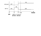
以上の処理によれば、停車時間が規定時間TLIMを超える前にアイドルストップ条件が成立すれば、アイドルストップ条件が成立したタイミングでアイドルストップが実行される(図5A)。しかしながら、アイドルストップ条件が成立しないまま停車時間が規定時間TLIMを超えた後は、アイドルストップ条件の成立・不成立に関係なく、アイルストップが禁止され、エンジン1の運転が継続される(図5B)。
According to the above processing, if the idle stop condition is satisfied before the stop time exceeds the specified time TLIM, the idle stop is executed at the timing when the idle stop condition is satisfied (FIG. 5A). However, after the stop time exceeds the specified time TLIM without the idling stop condition being met, the aisle stop is prohibited and the operation of the
つまり、アイドルストップが実行される場合は停車時間が規定時間TLIMを超える前に実行され、アイドルストップ条件が成立しないまま停車時間が規定時間TLIMを超えた後はアイドルストップが実行されることはないので、アイドルストップが実行される時期がばらつくことによる違和感を軽減することができる(請求項1に記載の発明に対応する効果)。 That is, when the idle stop is executed, it is executed before the stop time exceeds the specified time TLIM, and after the stop time exceeds the specified time TLIM without satisfying the idle stop condition, the idle stop is not executed. Therefore, it is possible to reduce a sense of incongruity due to variations in the timing at which the idle stop is executed (effect corresponding to the invention according to claim 1).
なお、アイドルストップの禁止はその禁止が判断された停車中でのみ有効で、車両が再発進した(停車中でない)と判断されると解除される。 It should be noted that the prohibition of idle stop is effective only when the vehicle is stopped, and is canceled when it is determined that the vehicle has restarted (not stopped).
続いて本発明の第2実施形態について説明する。 Next, a second embodiment of the present invention will be described.
第2実施形態では、停車中の燃料消費量を抑制し燃費をさらに向上させるために、アイドルストップ制御に加え、以下に説明するニュートラルアイドル制御(以下、「Nアイドル制御」という。)を所定条件のもと実行する。車両の全体構成は第1実施形態と同様である。 In the second embodiment, in order to further suppress fuel consumption while the vehicle is stopped and further improve fuel efficiency, neutral idle control (hereinafter referred to as “N idle control”) described below is a predetermined condition in addition to idle stop control. Run under. The overall configuration of the vehicle is the same as that of the first embodiment.
[Nアイドル制御]
Nアイドル制御は、停車中に発進用摩擦締結要素であるLowブレーキ32の供給油圧をLowブレーキ32が締結ぎりぎりの状態(Lowブレーキ32を構成する対向する係合部材が僅かに接触する状態、又は、接触する直前の状態)となる油圧まで下げてLowブレーキ32の伝達可能トルクを下げ、エンジン1及びメカオイルポンプ10mの負荷を下げて燃料消費量を抑制する制御である。なお、ここではLowブレーキ32が締結ぎりぎりの状態になるまで油圧を下げる例で説明するが、伝達可能トルクをエンジン1のトルクよりも低下させる制御であればよく、例えば、Lowブレーキ32が僅かに滑る状態まで油圧を下げる構成であってもよい。
[N idle control]
N idle control is a state in which the hydraulic pressure supplied to the
Nアイドル制御を実行するにあたり、コントローラ12は、以下に示す条件b1〜b7:
b1:車両が停車中(VSP=0)
b2:ブレーキペダルが踏み込まれている(ブレーキ液圧が所定値以上)
b3:アクセルペダルから足が離されている(アクセル開度APO=0)
b4:エンジン1の水温が所定範囲Ye内
b5:変速機4の油温が所定範囲Yt内
b6:車体の傾斜(≒路面勾配)が所定値以下
b7:副変速機構の変速段が1速(2速で停車した場合は2−1変速完了)
を判定する。そして、コントローラ12は、これらの条件b1〜b7が全て成立した場合にNアイドル条件成立と判定してNアイドル制御を許可し、Lowブレーキ32への供給油圧を下げて、変速機4をNアイドル状態にする。
In executing the N idle control, the
b1: Vehicle is stopped (VSP = 0)
b2: The brake pedal is depressed (the brake fluid pressure is equal to or higher than a predetermined value)
b3: The foot is released from the accelerator pedal (accelerator opening APO = 0)
b4: The water temperature of the
Determine. When all of these conditions b1 to b7 are satisfied, the
エンジン1の水温の所定範囲Yeは、エンジン1が安定して回転できる温度範囲に設定され、その下限値は所定範囲Xeの下限値よりも低く、上限値は所定範囲Xeの上限値よりも高く設定される。すなわち、所定範囲Yeは所定範囲Xeよりも広く、所定範囲Xeを含むよう設定される。
The predetermined range Ye of the water temperature of the
また、変速機4の油温の所定範囲Ytは、再発進時に所望の油圧応答性を実現できる温度範囲に設定され、その下限値は所定範囲Xtの下限値よりも低く、上限値は所定範囲Yeの上限値よりも高く設定される。すなわち、所定範囲Ytは所定範囲Xtよりも広く、所定範囲Xtを含むよう設定される。
Moreover, the predetermined range Yt of the oil temperature of the
アイドルストップ条件とNアイドル条件とはほぼ同じ条件であるが、エンジン1の水温条件及び変速機4の油温条件が上記の通り相違するので、通常はNアイドル条件がアイドルストップ条件よりも早い時期に成立する。
The idle stop condition and the N idle condition are substantially the same, but the water temperature condition of the
コントローラ12は、Nアイドル制御中も上記条件b1〜b7の成立が継続しているかを判定し、一つでも成立しなくなるとNアイドル条件不成立と判定してNアイドル制御を終了する、すなわち、Lowブレーキ32を完全締結する。
The
第2実施形態においても、第1実施形態と同様に、停車時間が規定時間TLIMを超える前にアイドルストップ条件が成立した場合はアイドルストップを実行し、アイドルストップ条件が成立しないまま停車時間が規定時間TLIMを超えた場合は、アイドルストップ条件が成立してもアイドルストップを行わない。 Also in the second embodiment, as in the first embodiment, if the idle stop condition is satisfied before the stop time exceeds the specified time TLIM, the idle stop is executed, and the stop time is specified without the idle stop condition being satisfied. When the time TLIM is exceeded, idle stop is not performed even if the idle stop condition is satisfied.
そして、第2実施形態はNアイドル条件を判定し、Nアイドル制御を実行するのであるが、停車時間が規定時間TLIMを超える前、かつ、アイドルストップ条件が成立していない時に、Nアイドル条件が成立しても、直ちにNアイドル制御を実行せず、停車時間が規定時間TLIMに達した時にNアイドル制御を実行する。 In the second embodiment, N idle conditions are determined and N idle control is executed. Before the stop time exceeds the specified time TLIM and when the idle stop condition is not satisfied, the N idle condition is satisfied. Even if it is established, the N idle control is not executed immediately, and the N idle control is executed when the stop time reaches the specified time TLIM.
Nアイドル条件が成立しても停車時間が規定時間TLIMに達する時までNアイドル制御を行わないのは、停車時間が規定時間TLIMを超えるまではアイドルストップのみがアイドルストップ条件の成否に応じて行われるようにすることで、Nアイドル状態からアイドルストップ状態に切り換えられることによるショックを回避するためである。 Even if the N idle condition is satisfied, the N idle control is not performed until the stop time reaches the specified time TLIM. Only the idle stop is performed according to the success or failure of the idle stop condition until the stop time exceeds the specified time TLIM. This is to avoid a shock caused by switching from the N idle state to the idle stop state.
上記切換え時にショックが生じるのは、Nアイドル制御ではLowブレーキ32を締結ぎりぎりの状態に制御するのに対し、アイドルストップでは再発進時の応答性を確保するためにLow32ブレーキを完全締結させるので、Lowブレーキ32への供給油圧が急激に切り換わるからである。
Shock occurs at the time of the above switching because the
なお、停車時間が規定時間TLIMを超えた後にアイドルストップ条件が成立してもアイドルストップを行わないのは上記の通りであるが、停車時間が規定時間TLIMを超えた後にNアイドル条件が成立した場合はNアイドル制御を実行する。これは、Nアイドル制御が開始されたことを運転者が認識することは殆どなく、どのタイミングで実行しても運転者に違和感を与えないからである。 As described above, the idle stop is not performed even if the idle stop condition is satisfied after the stop time exceeds the specified time TLIM. However, the N idle condition is satisfied after the stop time exceeds the specified time TLIM. In this case, N idle control is executed. This is because the driver hardly recognizes that the N idle control has started, and does not give the driver a sense of incongruity at any timing.
図6はコントローラ12が実行するアイドルストップ制御の内容を示したフローチャートである。これを参照しながら第2実施形態におけるアイドルストップ制御についてさらに説明する。このフローチャートは規定時間毎(例えば、10msec毎)に繰り返し実行される。
FIG. 6 is a flowchart showing the contents of the idle stop control executed by the
S21では、コントローラ12は、車両が停車中(VSP=0)か判定する。車両が停車中の場合は処理がS22に進み、そうでない場合は処理が終了する。処理が初めてS21からS22に進む場合は、停車時間を計測するタイマをスタートさせる。
In S21, the
S22では、コントローラ12は、停車時間が規定時間TLIMを超えたか判定する。停車時間が規定時間TLIMを超えていない場合は処理がS23に進み、停車時間が規定時間TLIMを超えている場合は処理がS27に進む。規定時間TILMの設定方法は第1実施形態と同様である。
In S22, the
S23では、コントローラ12は、アイドルストップ条件を判定する。具体的には、コントローラ12は、上記条件a1〜a8それぞれについて成立しているか判定する。
In S23, the
S24では、コントローラ12は、アイドルストップ条件が成立しているか判定する。コントローラ12は、上記条件a1〜a8が全て成立している場合にアイドルストップ条件が成立していると判定する。アイドルストップ条件が成立していると判定された場合は処理がS25に進み、そうでない場合は処理がS26に進む。
In S24, the
S25では、コントローラ12は、エンジン1のアイドルストップを実行する。すなわち、エンジン1への燃料供給を停止してエンジン1を停止させる。
In S25, the
S26では、コントローラ12は、Nアイドル条件を判定する。コントローラ12は、上記条件b1〜b7それぞれについて成立しているか判定する。
In S26, the
停車時間が規定時間TLIMを超えるまではS22〜S26が繰り返され、アイドルストップ条件が成立すればアイドルストップが実行される。Nアイドル制御に関しては、条件b1〜b7の判定のみが繰り返される。 S22 to S26 are repeated until the stop time exceeds the specified time TLIM, and if the idle stop condition is satisfied, the idle stop is executed. Regarding the N idle control, only the determinations of the conditions b1 to b7 are repeated.
一方、停車時間が規定時間TLIMを超えた場合は処理がS27に進む。S27では、コントローラ12は、アイドルストップ中か判定する。アイドルストップ中と判定された場合は、規定時間TLIM経過後もアイドルストップ条件が成立する限りアイドルストップを継続すべく、そのまま処理が終了する。そうでないと判定された場合は処理がS28に進む。
On the other hand, if the stop time exceeds the specified time TLIM, the process proceeds to S27. In S27, the
S28では、コントローラ12は、Nアイドル条件が成立しているか判定する。コントローラ12は、上記条件b1〜b7が全て成立している場合にNアイドル条件が成立していると判断する。
In S28, the
Nアイドル条件が成立している場合は、処理がS29に進み、コントローラ12は、Lowブレーキ32への供給油圧を低下させて、Nアイドル制御を実行する。Nアイドル条件が成立していない場合は処理がS30に進む。
When the N idle condition is satisfied, the process proceeds to S29, and the
S30では、コントローラ12は、Nアイドル条件が成立しているか判定する。コントローラ12は、上記条件b1〜b7が全て成立している場合にNアイドル条件が成立していると判断する。
In S30, the
したがって、上記制御によれば、停車時間が規定時間TLIMを超える前、かつ、アイドルストップ条件が成立していない時に、Nアイドル条件が成立しても、Nアイドル制御は実行されない。 Therefore, according to the above control, N idle control is not executed even if the N idle condition is satisfied before the stop time exceeds the specified time TLIM and when the idle stop condition is not satisfied.
停車時間が規定時間TLIMを超えるまでは、アイドルストップ条件の成否にいついての判定を繰り返し、成立した場合にはそのタイミングでエンジン1を自動的に停止する(図7A)。このときNアイドル制御は実行されていないので、Nアイドル状態からアイドルストップ状態への切換え時に生じるショックが生じることはない。
Until the stop time exceeds the specified time TLIM, the determination as to whether or not the idle stop condition is satisfied is repeated. When the stop time is satisfied, the
また、停車時間が規定時間TLIMを超えるまでにアイドルストップ条件が成立しなくても、Nアイドル条件が成立した場合は、停車時間が規定時間TLIMに達したタイミングでNアイドル制御が実行される(図7B)。 Further, even if the idle stop condition is not satisfied before the stop time exceeds the specified time TLIM, if the N idle condition is satisfied, N idle control is executed at the timing when the stop time reaches the specified time TLIM ( FIG. 7B).
このように、第2実施形態によれば、Nアイドル状態からアイドルストップ状態への切換えが行われることがないので、切換え時のショックを防止することができる。また、規定時間TLIM経過前にアイドルストップ条件が成立しない場合であっても、Nアイドル条件が成立すれば規定時間TLIM経過時にNアイドル制御が実行(規定時間TLIM経過後に成立した場合はそのタイミングで実行)されるので、停車中の燃料消費量を低減し、燃費を向上させることができる(請求項2に記載の発明に対応する効果)。 As described above, according to the second embodiment, since switching from the N idle state to the idle stop state is not performed, a shock at the time of switching can be prevented. Further, even if the idle stop condition is not satisfied before the lapse of the specified time TLIM, if the N idle condition is satisfied, the N idle control is executed when the specified time TLIM has elapsed (if the established time TLIM has elapsed, the timing is Therefore, it is possible to reduce fuel consumption while the vehicle is stopped and improve fuel efficiency (effect corresponding to the invention of claim 2).
続いて本発明の第3実施形態について説明する。 Next, a third embodiment of the present invention will be described.
第2実施形態では、Nアイドル状態からアイドルストップ状態に切り換えられる時のショック回避を目的として、停車時間が規定時間TLIMを超える前にNアイドル条件が成立しても規定時間TLIM経過時までNアイドル制御を行わないようにしていた。これに対し、第3実施形態ではショック防止よりも燃費向上を優先し、Nアイドル条件が成立した場合には直ちにNアイドル制御を実行し、その後、停車時間が規定時間TLIMを超える前にアイルストップ条件が成立した場合にはそのタイミングでNアイドル状態からアイドルストップ状態に切り換えるようにした。 In the second embodiment, for the purpose of avoiding a shock when switching from the N idle state to the idle stop state, even if the N idle condition is satisfied before the stop time exceeds the predetermined time TLIM, the N idle state is maintained until the predetermined time TLIM elapses. The control was not performed. On the other hand, in the third embodiment, improvement of fuel efficiency is prioritized over shock prevention. When the N idle condition is satisfied, the N idle control is immediately executed, and then the aisle stop is performed before the stop time exceeds the specified time TLIM. When the condition is satisfied, the N idle state is switched to the idle stop state at that timing.
その他の、車両の全体構成、アイドルストップ条件が成立しないまま停車時間が規定時間TLIMを超えた場合はアイドルストップを禁止する点、及び、停車時間が規定時間TLIMを超えた後にNアイドル条件が成立した場合にNアイドル制御を実行する点は、第2実施形態と同じである。 Other, the overall configuration of the vehicle, the point that the idle stop is prohibited when the stop time exceeds the specified time TLIM without the idle stop condition being satisfied, and the N idle condition is satisfied after the stop time exceeds the specified time TLIM In this case, N idle control is executed in the same manner as in the second embodiment.
図8はコントローラ12が実行するアイドルストップ制御の内容を示したフローチャートである。これを参照しながら第3実施形態におけるアイドルストップ制御についてさらに説明する。このフローチャートは規定時間毎(例えば、10msec毎)に繰り返し実行される。
FIG. 8 is a flowchart showing the contents of the idle stop control executed by the
S31では、コントローラ12は、車両が停車中(VSP=0)か判定する。車両が停車中の場合は処理がS32に進み、そうでない場合は処理が終了する。処理が初めてS31からS32に進む場合は、停車時間を計測するタイマをスタートさせる。
In S31, the
S32では、コントローラ12は、停車時間が規定時間TLIMを超えたか判定する。停車時間が規定時間TLIMを超えていない場合は処理がS33に進み、停車時間が規定時間TLIMを超えている場合は処理がS38に進む。規定時間TLIMの設定方法は第1実施形態と同様である。
In S32, the
S33では、コントローラ12は、アイドルストップ条件を判定する。具体的には、コントローラ12は、上記条件a1〜a8それぞれについて成立しているか判定する。
In S33, the
S34では、コントローラ12は、アイドルストップ条件が成立しているか判定する。コントローラ12は、上記条件a1〜a8が全て成立している場合にアイドルストップ条件が成立していると判定する。アイドルストップ条件が成立していると判定された場合は処理がS35に進み、そうでない場合は処理がS39に進む。
In S34, the
S35では、コントローラ12は、Nアイドル制御実行中であるか判定する。Nアイドル制御実行中であると判定された場合は処理がS36に進み、そうでない場合は処理がS37に進む。
In S35, the
S36では、コントローラ12は、Nアイドル制御を終了した後、アイドルストップを実行し、Nアイドル状態からアイドルストップ状態に切り換える。具体的には、Lowブレーキを完全締結し、その後、エンジン1への燃料供給を停止し、エンジン1を停止させる。
In S36, after ending the N idle control, the
S37では、コントローラ12は、エンジン1のアイドルストップを実行する。すなわち、エンジン1への燃料供給を停止し、エンジン1を停止させる。
In S37, the
一方、S32で停車時間が規定時間TLIMを超えたと判定されて進むS38では、コントローラ12は、アイドルストップ中か判定する。アイドルストップ中と判定された場合は、規定時間TLIM経過後もアイドルストップ条件が成立する限りアイドルストップを継続すべく、そのまま処理が終了する。そうでない場合は処理がS39に進む。
On the other hand, in S <b> 38, where it is determined that the stop time has exceeded the specified time TLIM in S <b> 32, the
S34でアイドルストップ条件不成立と判定された場合、又は、S38でアイドルストップ中でないと判定されて進むS39では、コントローラ12は、Nアイドル条件を判定する。コントローラ12は、上記条件b1〜b7それぞれについて成立しているか判定する。
When it is determined in S34 that the idle stop condition is not satisfied, or in S39 which proceeds after it is determined that the idle stop is not being performed in S38, the
S40では、Nアイドル条件が成立しているか判断する。コントローラ12は、上記条件b1〜b7が全て成立している場合にNアイドル条件が成立していると判定する。Nアイドル条件が成立していると判定された場合は処理がS41に進み、そうでない場合は処理が終了する。
In S40, it is determined whether the N idle condition is satisfied. The
S41では、コントローラ12は、Lowブレーキ32への供給油圧を低下させて、Nアイドル制御を実行する。
In S41, the
したがって、第3実施形態によれば、アイドルストップ条件が成立していなくても、Nアイドル条件が成立すれば、停車時間に関係なくNアイドル制御が直ちに実施されるので、第2実施形態と比較して燃費を向上させることができる(請求項3に記載の発明に対応する効果)。 Therefore, according to the third embodiment, even if the idle stop condition is not satisfied, if the N idle condition is satisfied, the N idle control is immediately performed regardless of the stop time. Thus, fuel consumption can be improved (effect corresponding to the invention of claim 3).
また、Nアイドル制御中であっても停車時間が規定時間TLIMを超える前であれば、アイドルストップ条件が成立するとNアイドル制御が中止され、Nアイドル制御よりも燃費向上効果の高いアイドルストップが実行されるので、より一層燃費を向上させることができる(請求項4に記載の発明に対応する効果)。図9はこの時の様子を示したタイムチャートである。 In addition, even during N idle control, if the stop time exceeds the specified time TLIM, the N idle control is stopped when the idle stop condition is satisfied, and the idle stop with higher fuel efficiency improvement than the N idle control is executed. Therefore, fuel consumption can be further improved (effect corresponding to the invention of claim 4). FIG. 9 is a time chart showing the situation at this time.
なお、S36でNアイドル状態からアイドルストップ状態に切り換える時、Lowブレーキ32を完全締結してからエンジン1を停止しているが、エンジン1を停止させてからLowブレーキ32を完全締結するようにしてもよい。これにより、切換え時のショックを低減することが可能である。
When switching from the N idle state to the idle stop state in S36, the
以上、本発明の実施形態について説明したが、上記実施形態は本発明の適用例を示したものに過ぎず、本発明の技術的範囲を上記実施形態の具体的構成に限定する趣旨ではない。本発明の趣旨を逸脱しない範囲で種々の変更が可能である。 The embodiment of the present invention has been described above, but the above embodiment is merely an example of application of the present invention, and is not intended to limit the technical scope of the present invention to the specific configuration of the above embodiment. Various modifications can be made without departing from the spirit of the present invention.
例えば、変速機4は上記バリエータ20と副変速機構30とを組み合わせた変速機に限定されない。変速機4は、副変速機構を備えない通常の無段変速機、又は、有段の自動変速機であってもよい。この場合、Nアイドル制御時に伝達可能トルクを低下させる発進用摩擦締結要素は前後進切換え機構のフォワードクラッチである。
For example, the
1…エンジン
4…無段変速機
12…コントローラ
32…Lowブレーキ(発進用摩擦締結要素)
DESCRIPTION OF
Claims (4)
アイドルストップ条件が成立したか判定するアイドルストップ条件判定手段と、
停車時間が規定時間を超える前に前記アイドルストップ条件が成立した場合は前記アイドルストップを実行し、前記アイドルストップ条件が成立しないまま前記停車時間が前記規定時間を超えた後は前記アイドルストップを禁止するエンジン制御手段と、
を備えたことを特徴とするアイドルストップ車両。 An idle stop vehicle that executes an idle stop that automatically stops the engine while stopped,
Idle stop condition determining means for determining whether the idle stop condition is satisfied;
If the idle stop condition is satisfied before the stop time exceeds the specified time, the idle stop is executed, and the idle stop is prohibited after the stop time exceeds the specified time without the idle stop condition being satisfied. Engine control means for
An idle stop vehicle characterized by comprising:
前記エンジンの出力回転を駆動輪に伝達する自動変速機と、
前記自動変速機の発進用摩擦締結要素の伝達可能トルクを前記エンジンのトルクよりも低下させるNアイドル制御を実行するNアイドル制御実行手段と、
前記Nアイドル制御を許可するNアイドル条件が成立したか判定するNアイドル条件判定手段と、
前記停車時間が前記規定時間を超える前に前記Nアイドル条件が成立しかつ前記アイドルストップ条件が成立しなかった場合は、前記停車時間が前記規定時間に達した時に前記Nアイドル制御実行手段により前記Nアイドル制御を実行する変速機制御手段と、
を備えたことを特徴とするアイドルストップ車両。 The idle stop vehicle according to claim 1,
An automatic transmission for transmitting the output rotation of the engine to drive wheels;
N idle control execution means for executing N idle control for reducing the transmittable torque of the starting frictional engagement element of the automatic transmission to be lower than the torque of the engine;
N idle condition determining means for determining whether an N idle condition for permitting the N idle control is satisfied;
If the N idle condition is satisfied before the stop time exceeds the specified time and the idle stop condition is not satisfied, the N idle control execution means performs the stop when the stop time reaches the specified time. Transmission control means for executing N idle control;
An idle stop vehicle characterized by comprising:
前記エンジンの動力を駆動輪に伝達する自動変速機と、
前記自動変速機を発進用摩擦締結要素の伝達可能トルクを前記エンジンのトルクよりも低下させるNアイドル制御を実行するNアイドル制御実行手段と、
前記Nアイドル制御を許可するNアイドル条件が成立したか判定するNアイドル条件判定手段と、
前記停車時間が前記規定時間を超える前、かつ、前記アイドルストップ条件が成立していない時に、前記Nアイドル条件が成立した場合は、前記Nアイドル条件が成立した時に前記Nアイドル制御実行手段により前記Nアイドル制御を実行する変速機制御手段と、
を備えたことを特徴とするアイドルストップ車両。 The idle stop vehicle according to claim 1,
An automatic transmission for transmitting the power of the engine to drive wheels;
N idle control execution means for executing N idle control for reducing the transmittable torque of the friction engagement element for starting the automatic transmission below the torque of the engine;
N idle condition determining means for determining whether an N idle condition for permitting the N idle control is satisfied;
If the N idle condition is satisfied before the stop time exceeds the specified time and the idle stop condition is not satisfied, the N idle control execution means executes the N idle condition when the N idle condition is satisfied. Transmission control means for executing N idle control;
An idle stop vehicle characterized by comprising:
前記Nアイドル制御実行手段により前記Nアイドル制御を実行中、かつ、前記停車時間が前記規定時間を超える前に前記アイドルストップ条件が成立した場合は、前記アイドルストップ条件が成立した時に前記変速機制御手段が前記Nアイドル制御実行手段による前記Nアイドル制御を終了するとともに前記エンジン制御手段が前記アイドルストップを実行する、
ことを特徴とするアイドルストップ車両。 An idle stop vehicle according to claim 3,
When the N idle control is being executed by the N idle control execution means and the idle stop condition is satisfied before the stop time exceeds the specified time, the transmission control is performed when the idle stop condition is satisfied. Means terminates the N idle control by the N idle control execution means, and the engine control means executes the idle stop.
An idle stop vehicle characterized by that.
Priority Applications (6)
| Application Number | Priority Date | Filing Date | Title |
|---|---|---|---|
| JP2010176097A JP5039815B2 (en) | 2010-08-05 | 2010-08-05 | Idle stop vehicle |
| KR1020110062039A KR101354320B1 (en) | 2010-08-05 | 2011-06-27 | Idle stop vehicle |
| EP11005770A EP2416001A1 (en) | 2010-08-05 | 2011-07-14 | Idle stop vehicle and control method thereof |
| US13/187,001 US8700278B2 (en) | 2010-08-05 | 2011-07-20 | Idle stop vehicle and control method thereof |
| CN201110207858.1A CN102371996B (en) | 2010-08-05 | 2011-07-25 | Idle stop vehicle and control method thereof |
| KR1020130067745A KR20130080027A (en) | 2010-08-05 | 2013-06-13 | Idle stop vehicle |
Applications Claiming Priority (1)
| Application Number | Priority Date | Filing Date | Title |
|---|---|---|---|
| JP2010176097A JP5039815B2 (en) | 2010-08-05 | 2010-08-05 | Idle stop vehicle |
Publications (2)
| Publication Number | Publication Date |
|---|---|
| JP2012036781A JP2012036781A (en) | 2012-02-23 |
| JP5039815B2 true JP5039815B2 (en) | 2012-10-03 |
Family
ID=44581931
Family Applications (1)
| Application Number | Title | Priority Date | Filing Date |
|---|---|---|---|
| JP2010176097A Active JP5039815B2 (en) | 2010-08-05 | 2010-08-05 | Idle stop vehicle |
Country Status (5)
| Country | Link |
|---|---|
| US (1) | US8700278B2 (en) |
| EP (1) | EP2416001A1 (en) |
| JP (1) | JP5039815B2 (en) |
| KR (2) | KR101354320B1 (en) |
| CN (1) | CN102371996B (en) |
Cited By (1)
| Publication number | Priority date | Publication date | Assignee | Title |
|---|---|---|---|---|
| JP2012255384A (en) * | 2011-06-09 | 2012-12-27 | Mitsubishi Motors Corp | Vehicle control apparatus |
Families Citing this family (23)
| Publication number | Priority date | Publication date | Assignee | Title |
|---|---|---|---|---|
| JP5230703B2 (en) * | 2010-09-03 | 2013-07-10 | ジヤトコ株式会社 | Engine automatic stop vehicle and control method thereof |
| KR101360500B1 (en) * | 2011-12-14 | 2014-02-10 | 기아자동차주식회사 | How to charge the battery of a hybrid electric vehicle |
| GB201201222D0 (en) * | 2012-01-25 | 2012-03-07 | Jaguar Cars | Motor vehicle and method of control of a motor vehicle |
| JP2013181408A (en) * | 2012-02-29 | 2013-09-12 | Toyota Motor Corp | Control device for vehicle |
| US9279496B2 (en) * | 2012-04-02 | 2016-03-08 | Jatco Ltd | Control device for continuously variable transmission |
| US9243600B2 (en) * | 2012-09-04 | 2016-01-26 | Ford Global Technologies, Llc | Method and system for improving automatic engine stopping |
| JP5937750B2 (en) * | 2013-03-12 | 2016-06-22 | ジヤトコ株式会社 | Vehicle control apparatus and vehicle control method |
| DE102013009220A1 (en) * | 2013-05-31 | 2014-12-04 | Volkswagen Aktiengesellschaft | Method for operating a vehicle with an internal combustion engine with a start-stop function |
| JP6006876B2 (en) * | 2013-07-23 | 2016-10-12 | ジヤトコ株式会社 | VEHICLE CONTROL DEVICE AND ITS CONTROL METHOD |
| JP6232245B2 (en) * | 2013-10-11 | 2017-11-15 | 本田技研工業株式会社 | Vehicle control device |
| JP6084154B2 (en) * | 2013-12-11 | 2017-02-22 | ジヤトコ株式会社 | Control device for vehicle transmission |
| JP6053666B2 (en) * | 2013-12-11 | 2016-12-27 | ジヤトコ株式会社 | Control device for continuously variable transmission |
| US11279357B2 (en) * | 2013-12-25 | 2022-03-22 | Denso Corporation | Vehicle diagnosis system and method |
| CN105484881A (en) * | 2014-09-18 | 2016-04-13 | 大陆汽车电子(长春)有限公司 | Vehicle engine idle-speed start and stop control method, device and system |
| US9624893B2 (en) | 2015-04-27 | 2017-04-18 | International Truck Intellectual Property Company, Llc | Engine shut-off and re-start strategy |
| KR101714307B1 (en) * | 2016-03-15 | 2017-03-08 | 현대자동차주식회사 | A method for controlling restart of vehicle having isg-auto hold system and an apparatus the same |
| CN106274885B (en) * | 2016-08-31 | 2018-07-10 | 安徽江淮汽车集团股份有限公司 | Vehicle start-up and shut-down control method |
| CN106828502B (en) * | 2016-12-30 | 2020-06-26 | 中国第一汽车股份有限公司 | Method for identifying bad driving behavior of automobile driver when stepping on accelerator |
| US10112612B2 (en) * | 2017-02-16 | 2018-10-30 | Ford Global Technologies, Llc | Coordinated actuation of vehicle stop modes |
| FR3080594B1 (en) * | 2018-04-26 | 2020-06-19 | Manitou Bf | ROLLING MACHINE EQUIPPED WITH AN AUTOMATIC STOPPING FUNCTION OF THE HEAT ENGINE AND METHOD FOR OPTIMIZING THE STOP CONDITIONS OF SUCH A MACHINE |
| JP6936275B2 (en) * | 2019-04-22 | 2021-09-15 | 本田技研工業株式会社 | vehicle |
| US11724711B2 (en) * | 2020-01-21 | 2023-08-15 | Nissan Motor Co., Ltd. | Vehicle idling stop control method and vehicle idling stop control device |
| US20250153722A1 (en) * | 2023-11-13 | 2025-05-15 | GM Global Technology Operations LLC | Protected idle system for a vehicle |
Family Cites Families (12)
| Publication number | Priority date | Publication date | Assignee | Title |
|---|---|---|---|---|
| FR2795770B1 (en) * | 1999-06-30 | 2001-09-21 | Valeo Equip Electr Moteur | METHODS AND SYSTEMS FOR AUTOMATICALLY CONTROLLING THE SHUTDOWN AND RESTART OF A HEAT ENGINE OF A VEHICLE DURING TEMPORARY IMMOBILIZATION THEREOF |
| JP2002029289A (en) * | 2000-07-18 | 2002-01-29 | Mitsubishi Motors Corp | Control device for automatic transmission |
| JP2002256921A (en) * | 2001-02-28 | 2002-09-11 | Toyota Motor Corp | Vehicle control device |
| JP3858629B2 (en) | 2001-06-14 | 2006-12-20 | トヨタ自動車株式会社 | Road surface gradient measuring device and engine automatic stop / start device |
| US6556910B2 (en) * | 2001-08-31 | 2003-04-29 | Aisin Aw Co., Ltd. | Control apparatus and method for vehicle having an idle stop function |
| KR20040021879A (en) * | 2002-09-05 | 2004-03-11 | 현대자동차주식회사 | Engine control system and method for hybrid electric vehicle |
| DE10316604A1 (en) * | 2003-04-11 | 2004-11-04 | Bayerische Motoren Werke Ag | Method for automatically switching off an internal combustion engine |
| DE102007009831B4 (en) * | 2007-02-28 | 2021-07-22 | Bayerische Motoren Werke Aktiengesellschaft | Display trip unit in a motor vehicle with an automatic start-stop function |
| JP5084681B2 (en) * | 2008-09-24 | 2012-11-28 | ダイハツ工業株式会社 | Idle stop control device |
| JP2010163879A (en) * | 2009-01-13 | 2010-07-29 | Honda Motor Co Ltd | Idle stop control device |
| JP5280231B2 (en) | 2009-02-02 | 2013-09-04 | パナソニック株式会社 | Zoom lens system, interchangeable lens device, and camera system |
| CN101492044A (en) * | 2009-02-24 | 2009-07-29 | 江苏大学 | Device and method for judging vehicle effective idling-stopping condition |
-
2010
- 2010-08-05 JP JP2010176097A patent/JP5039815B2/en active Active
-
2011
- 2011-06-27 KR KR1020110062039A patent/KR101354320B1/en not_active Expired - Fee Related
- 2011-07-14 EP EP11005770A patent/EP2416001A1/en not_active Withdrawn
- 2011-07-20 US US13/187,001 patent/US8700278B2/en active Active
- 2011-07-25 CN CN201110207858.1A patent/CN102371996B/en active Active
-
2013
- 2013-06-13 KR KR1020130067745A patent/KR20130080027A/en not_active Abandoned
Cited By (1)
| Publication number | Priority date | Publication date | Assignee | Title |
|---|---|---|---|---|
| JP2012255384A (en) * | 2011-06-09 | 2012-12-27 | Mitsubishi Motors Corp | Vehicle control apparatus |
Also Published As
| Publication number | Publication date |
|---|---|
| KR20120013888A (en) | 2012-02-15 |
| US8700278B2 (en) | 2014-04-15 |
| CN102371996A (en) | 2012-03-14 |
| EP2416001A1 (en) | 2012-02-08 |
| CN102371996B (en) | 2014-06-25 |
| KR101354320B1 (en) | 2014-01-22 |
| US20120035817A1 (en) | 2012-02-09 |
| JP2012036781A (en) | 2012-02-23 |
| KR20130080027A (en) | 2013-07-11 |
Similar Documents
| Publication | Publication Date | Title |
|---|---|---|
| JP5039815B2 (en) | Idle stop vehicle | |
| JP5039819B2 (en) | Coast stop vehicle and coast stop method | |
| JP5548599B2 (en) | Coast stop vehicle and control method thereof | |
| JP5526006B2 (en) | Coast stop vehicle and coast stop vehicle control method | |
| JP5526005B2 (en) | Coast stop vehicle and coast stop vehicle control method | |
| JP5230703B2 (en) | Engine automatic stop vehicle and control method thereof | |
| KR101456755B1 (en) | Coast stop vehicle and control method for the same | |
| JP5756002B2 (en) | Vehicle control apparatus and vehicle control method | |
| JP5344081B2 (en) | Control device for continuously variable transmission for vehicle | |
| JP5740293B2 (en) | Vehicle control apparatus and vehicle control method | |
| KR101356328B1 (en) | Coast stop vehicle | |
| JP2012117424A (en) | Vehicle control apparatus | |
| JP5717801B2 (en) | Coast stop vehicle control device | |
| JP6547010B2 (en) | Control device of vehicle and control method of vehicle | |
| JP5860150B2 (en) | Automatic transmission for vehicles | |
| WO2021059636A1 (en) | Vehicle control device and vehicle control method | |
| JP2015135165A (en) | Continuously variable transmission, and control method thereof |
Legal Events
| Date | Code | Title | Description |
|---|---|---|---|
| A621 | Written request for application examination |
Free format text: JAPANESE INTERMEDIATE CODE: A621 Effective date: 20120214 |
|
| A977 | Report on retrieval |
Free format text: JAPANESE INTERMEDIATE CODE: A971007 Effective date: 20120615 |
|
| TRDD | Decision of grant or rejection written | ||
| A01 | Written decision to grant a patent or to grant a registration (utility model) |
Free format text: JAPANESE INTERMEDIATE CODE: A01 Effective date: 20120626 |
|
| A01 | Written decision to grant a patent or to grant a registration (utility model) |
Free format text: JAPANESE INTERMEDIATE CODE: A01 |
|
| A61 | First payment of annual fees (during grant procedure) |
Free format text: JAPANESE INTERMEDIATE CODE: A61 Effective date: 20120709 |
|
| FPAY | Renewal fee payment (event date is renewal date of database) |
Free format text: PAYMENT UNTIL: 20150713 Year of fee payment: 3 |
|
| R150 | Certificate of patent or registration of utility model |
Ref document number: 5039815 Country of ref document: JP Free format text: JAPANESE INTERMEDIATE CODE: R150 Free format text: JAPANESE INTERMEDIATE CODE: R150 |
|
| R250 | Receipt of annual fees |
Free format text: JAPANESE INTERMEDIATE CODE: R250 |