JP5028008B2 - Fluorescence endoscope device - Google Patents
Fluorescence endoscope device Download PDFInfo
- Publication number
- JP5028008B2 JP5028008B2 JP2005347849A JP2005347849A JP5028008B2 JP 5028008 B2 JP5028008 B2 JP 5028008B2 JP 2005347849 A JP2005347849 A JP 2005347849A JP 2005347849 A JP2005347849 A JP 2005347849A JP 5028008 B2 JP5028008 B2 JP 5028008B2
- Authority
- JP
- Japan
- Prior art keywords
- wavelength
- light
- fluorescence
- optical filter
- transmittance
- Prior art date
- Legal status (The legal status is an assumption and is not a legal conclusion. Google has not performed a legal analysis and makes no representation as to the accuracy of the status listed.)
- Expired - Fee Related
Links
Images


Classifications
-
- A—HUMAN NECESSITIES
- A61—MEDICAL OR VETERINARY SCIENCE; HYGIENE
- A61B—DIAGNOSIS; SURGERY; IDENTIFICATION
- A61B1/00—Instruments for performing medical examinations of the interior of cavities or tubes of the body by visual or photographical inspection, e.g. endoscopes; Illuminating arrangements therefor
- A61B1/06—Instruments for performing medical examinations of the interior of cavities or tubes of the body by visual or photographical inspection, e.g. endoscopes; Illuminating arrangements therefor with illuminating arrangements
- A61B1/0638—Instruments for performing medical examinations of the interior of cavities or tubes of the body by visual or photographical inspection, e.g. endoscopes; Illuminating arrangements therefor with illuminating arrangements providing two or more wavelengths
-
- A—HUMAN NECESSITIES
- A61—MEDICAL OR VETERINARY SCIENCE; HYGIENE
- A61B—DIAGNOSIS; SURGERY; IDENTIFICATION
- A61B1/00—Instruments for performing medical examinations of the interior of cavities or tubes of the body by visual or photographical inspection, e.g. endoscopes; Illuminating arrangements therefor
- A61B1/00002—Operational features of endoscopes
- A61B1/00043—Operational features of endoscopes provided with output arrangements
- A61B1/00045—Display arrangement
- A61B1/0005—Display arrangement combining images e.g. side-by-side, superimposed or tiled
-
- A—HUMAN NECESSITIES
- A61—MEDICAL OR VETERINARY SCIENCE; HYGIENE
- A61B—DIAGNOSIS; SURGERY; IDENTIFICATION
- A61B1/00—Instruments for performing medical examinations of the interior of cavities or tubes of the body by visual or photographical inspection, e.g. endoscopes; Illuminating arrangements therefor
- A61B1/00163—Optical arrangements
- A61B1/00186—Optical arrangements with imaging filters
-
- A—HUMAN NECESSITIES
- A61—MEDICAL OR VETERINARY SCIENCE; HYGIENE
- A61B—DIAGNOSIS; SURGERY; IDENTIFICATION
- A61B1/00—Instruments for performing medical examinations of the interior of cavities or tubes of the body by visual or photographical inspection, e.g. endoscopes; Illuminating arrangements therefor
- A61B1/04—Instruments for performing medical examinations of the interior of cavities or tubes of the body by visual or photographical inspection, e.g. endoscopes; Illuminating arrangements therefor combined with photographic or television appliances
- A61B1/043—Instruments for performing medical examinations of the interior of cavities or tubes of the body by visual or photographical inspection, e.g. endoscopes; Illuminating arrangements therefor combined with photographic or television appliances for fluorescence imaging
-
- A—HUMAN NECESSITIES
- A61—MEDICAL OR VETERINARY SCIENCE; HYGIENE
- A61B—DIAGNOSIS; SURGERY; IDENTIFICATION
- A61B1/00—Instruments for performing medical examinations of the interior of cavities or tubes of the body by visual or photographical inspection, e.g. endoscopes; Illuminating arrangements therefor
- A61B1/06—Instruments for performing medical examinations of the interior of cavities or tubes of the body by visual or photographical inspection, e.g. endoscopes; Illuminating arrangements therefor with illuminating arrangements
- A61B1/063—Instruments for performing medical examinations of the interior of cavities or tubes of the body by visual or photographical inspection, e.g. endoscopes; Illuminating arrangements therefor with illuminating arrangements for monochromatic or narrow-band illumination
-
- A—HUMAN NECESSITIES
- A61—MEDICAL OR VETERINARY SCIENCE; HYGIENE
- A61B—DIAGNOSIS; SURGERY; IDENTIFICATION
- A61B1/00—Instruments for performing medical examinations of the interior of cavities or tubes of the body by visual or photographical inspection, e.g. endoscopes; Illuminating arrangements therefor
- A61B1/06—Instruments for performing medical examinations of the interior of cavities or tubes of the body by visual or photographical inspection, e.g. endoscopes; Illuminating arrangements therefor with illuminating arrangements
- A61B1/0646—Instruments for performing medical examinations of the interior of cavities or tubes of the body by visual or photographical inspection, e.g. endoscopes; Illuminating arrangements therefor with illuminating arrangements with illumination filters
-
- A—HUMAN NECESSITIES
- A61—MEDICAL OR VETERINARY SCIENCE; HYGIENE
- A61B—DIAGNOSIS; SURGERY; IDENTIFICATION
- A61B1/00—Instruments for performing medical examinations of the interior of cavities or tubes of the body by visual or photographical inspection, e.g. endoscopes; Illuminating arrangements therefor
- A61B1/06—Instruments for performing medical examinations of the interior of cavities or tubes of the body by visual or photographical inspection, e.g. endoscopes; Illuminating arrangements therefor with illuminating arrangements
- A61B1/0655—Control therefor
-
- H—ELECTRICITY
- H04—ELECTRIC COMMUNICATION TECHNIQUE
- H04N—PICTORIAL COMMUNICATION, e.g. TELEVISION
- H04N23/00—Cameras or camera modules comprising electronic image sensors; Control thereof
- H04N23/50—Constructional details
- H04N23/555—Constructional details for picking-up images in sites, inaccessible due to their dimensions or hazardous conditions, e.g. endoscopes or borescopes
Landscapes
- Health & Medical Sciences (AREA)
- Life Sciences & Earth Sciences (AREA)
- Surgery (AREA)
- Engineering & Computer Science (AREA)
- Biomedical Technology (AREA)
- Molecular Biology (AREA)
- Pathology (AREA)
- Radiology & Medical Imaging (AREA)
- Nuclear Medicine, Radiotherapy & Molecular Imaging (AREA)
- Biophysics (AREA)
- Physics & Mathematics (AREA)
- Heart & Thoracic Surgery (AREA)
- Medical Informatics (AREA)
- Optics & Photonics (AREA)
- Animal Behavior & Ethology (AREA)
- General Health & Medical Sciences (AREA)
- Public Health (AREA)
- Veterinary Medicine (AREA)
- Multimedia (AREA)
- Signal Processing (AREA)
- Endoscopes (AREA)
- Instruments For Viewing The Inside Of Hollow Bodies (AREA)
- Investigating, Analyzing Materials By Fluorescence Or Luminescence (AREA)
Abstract
Description
本発明は、励起光を生体に照射し、生体から発した蛍光を撮像して蛍光画像を得る蛍光内視鏡装置及びそれに用いる撮像ユニットに関し、より詳しくは、内視鏡観察下で生体内に発生した病変の診断を行うことができる蛍光内視鏡装置及びそれに用いる撮像ユニットに関するものである。 The present invention relates to a fluorescence endoscope apparatus that irradiates a living body with excitation light and captures fluorescence emitted from the living body to obtain a fluorescence image, and an imaging unit used therefor, and more specifically, in vivo under endoscopic observation. The present invention relates to a fluorescence endoscope apparatus capable of diagnosing a lesion that has occurred and an imaging unit used therefor.
生体内に発生した病変の診断を行うための内視鏡装置が広く知られている。例えば、生体組織表面に励起光を照射して生体組織に含まれる蛍光物質を励起し、生体組織から発した蛍光を撮像することで蛍光画像を取得するようにした蛍光内視鏡装置が実用化されている。蛍光内視鏡装置は、取得した蛍光画像に含まれる情報に基づいて生体組織に発生した病変の診断を行うための装置である。 Endoscopic apparatuses for diagnosing lesions occurring in a living body are widely known. For example, a fluorescent endoscope device that acquires fluorescent images by irradiating the surface of a living tissue with excitation light to excite fluorescent substances contained in the living tissue and imaging the fluorescence emitted from the living tissue is put into practical use. Has been. The fluorescence endoscope apparatus is an apparatus for diagnosing a lesion generated in a living tissue based on information included in an acquired fluorescence image.
生体組織表面に励起光を照射して生体組織表面からの自家蛍光を検出する場合、正常組織と病変組織とでは自家蛍光の強度が異なることが知られている。そこで、生体組織の自家蛍光画像から得られる蛍光強度分布を解析することで、病変組織の領域と正常組織の領域を区分けすることができる。生体組織は層構造を呈しており、このうち粘膜下層には自家蛍光を発するコラーゲンやエラスチンが多く含まれている。粘膜下層よりも上層に位置する粘膜層の組織に病変による構造変化が生じると、コラーゲンやエラスチンの自家蛍光は、粘膜表層に到達するまでにその影響を強く受けて減衰する。このため、コラーゲンやエラスチンの主要な自家蛍光波長である420nm〜600nmの波長範囲の蛍光強度を検出することで、粘膜層に発生した病変組織の領域を識別するための情報を取得することができる。 When detecting autofluorescence from the surface of a living tissue by irradiating the surface of the living tissue with excitation light, it is known that the intensity of the autofluorescence differs between a normal tissue and a diseased tissue. Thus, by analyzing the fluorescence intensity distribution obtained from the autofluorescence image of the living tissue, the region of the diseased tissue and the region of the normal tissue can be distinguished. Living tissue has a layered structure, and among these, the submucosa is rich in collagen and elastin that emit autofluorescence. When structural changes due to lesions occur in the tissue of the mucosal layer located above the submucosa, autofluorescence of collagen and elastin is strongly influenced and attenuated before reaching the surface of the mucosa. For this reason, information for identifying the region of the lesion tissue generated in the mucosa layer can be obtained by detecting the fluorescence intensity in the wavelength range of 420 nm to 600 nm, which is the main autofluorescence wavelength of collagen and elastin. .
一方、生体内に存在する有機化合物であるポルフィリンは腫瘍に蓄積される傾向があることが知られている。ポルフィリンは、コラーゲンやエラスチンと同様に、青色から緑色の波長範囲の励起光によって、630nm付近にピーク波長を持つ蛍光を発するので、630nmを含むごく狭い波長範囲の蛍光強度を検出することで、生体組織に腫瘍が発生していることを示す情報を取得することができる。また、ポルフィリンは5ALA(5-aminolevulinic acid)のような蛍光薬剤を体外から投与することでも腫瘍に蓄積させることが可能である。このように、生体組織からの自家蛍光スペクトルを波長帯域ごとに分けて検出することで、それぞれのスペクトル帯域に含まれる、異なる情報を取り出すことができる。 On the other hand, it is known that porphyrin, which is an organic compound present in the living body, tends to accumulate in tumors. Porphyrin, like collagen and elastin, emits fluorescence having a peak wavelength in the vicinity of 630 nm by excitation light in the blue to green wavelength range. Therefore, by detecting fluorescence intensity in a very narrow wavelength range including 630 nm, Information indicating that a tumor has occurred in the tissue can be acquired. Porphyrin can also be accumulated in a tumor by administering a fluorescent agent such as 5ALA (5-aminolevulinic acid) from outside the body. In this manner, by detecting the autofluorescence spectrum from the living tissue separately for each wavelength band, different information included in each spectrum band can be extracted.
生体組織の自家蛍光を利用して生体組織の診断を行う手法および装置として、例えば、次の特許文献1に開示されるものが知られている。
特許文献1に開示される蛍光内視鏡装置は、病変組織の自家蛍光強度が正常組織の自家蛍光強度と実質的に相違するスペクトル帯域と、病変組織の自家蛍光強度が正常組織の自家蛍光強度と実質的に等しくなるスペクトル帯域の蛍光画像を利用して、病変組織の領域を明瞭に描出するものである。これにより、病変組織を周囲の正常な組織から明確に識別することができる。
The fluorescence endoscope apparatus disclosed in
また、生体に発生した病変組織に対して親和性を有し、励起光を吸収して蛍光を発する物質を利用して生体組織における病変組織の有無を診断する手法が知られている。この場合、まず生体外から病変の存在が疑われる部位に対して蛍光物質を投与する。少し時間を置くと、蛍光物質は病変組織に選択的に結合するので、その後に、その部位に対して励起光を照射して蛍光物質からの蛍光を検出することで、生体に発生した病変組織の領域を明らかにすることができる。このような蛍光物質としては、例えば、次の特許文献2および特許文献3に開示される蛍光プローブが知られている。
蛍光プローブは、腫瘍などの病変組織が出現して成長していく過程に特異的に関与する物質(以下、検出対象物質とよぶ)を分子レベルで捉えて結合する部分と、蛍光を発する色素の部分から構成されている。蛍光を発する色素は、従来市販されている種々の色素から選択することが可能である。 A fluorescent probe captures and binds a substance that specifically participates in the process of appearance and growth of a diseased tissue such as a tumor (hereinafter referred to as a detection target substance) and a dye that emits fluorescence. It consists of parts. The dye that emits fluorescence can be selected from various dyes that have been commercially available.
例えば、特許文献2には、600nm〜1200nmの波長範囲に励起波長ピークおよび蛍光波長ピークをもつ市販の色素で構成される蛍光プローブが開示されている。このような蛍光プローブは、比較的安価に製造が可能であり、既に生体への安全性の検証が進められている。
For example,
また、特許文献3には、検出対象物質を捕捉する前には実質的に蛍光の発光が抑制され、検出対象物質を捕捉した後には実質的に強い蛍光を発する物質に変化する性質を有する蛍光プローブが開示されている。このような蛍光プローブは、検出対象物質と結合したときにのみ蛍光を発するので、病変を検出する精度を向上させることができるという利点を有している。また、蛍光プローブは、特定の検出対象物質を選択的に捉えて結合させるように設計することができるので、病変に固有の特徴に関与している物質をターゲットとして選ぶことで、その病変のもつ特異性(例えば癌であるかどうか)の分析および診断に役立たせることが可能である。
Further,
内視鏡観察下で生体組織に発生した病変の診断を行う場合には、内視鏡を通して取得した画像に含まれる病変に関する情報が多いほど診断精度を向上させることができる。そのため、蛍光内視鏡装置には、可視波長領域において病変組織からの自家蛍光画像を取得する機能と、赤色から近赤外波長領域において病変組織と結合した蛍光プローブからの蛍光画像を取得する機能の両方が備えられているのが望ましい。また、それぞれの蛍光画像に含まれる病変に関する情報を利用して、診断に有用な画像に加工する機能を有するのが望ましい。 When diagnosing a lesion occurring in a living tissue under endoscopic observation, the diagnosis accuracy can be improved as the amount of information regarding the lesion included in an image acquired through the endoscope increases. Therefore, the fluorescence endoscope apparatus has a function of acquiring an autofluorescence image from a lesion tissue in the visible wavelength region and a function of acquiring a fluorescence image from a fluorescent probe combined with the lesion tissue in a red to near-infrared wavelength region. It is desirable to have both. In addition, it is desirable to have a function of processing information that is useful for diagnosis by using information on a lesion included in each fluorescent image.
しかし、特許文献1に開示されているような従来の蛍光内視鏡装置では、上記のような複合的な情報の取得と画像の加工を行うことは不可能である。また、特許文献2および3には、蛍光プローブの構造や蛍光プローブを生体に導入して蛍光を検出するまでの手順については開示されているものの、蛍光の検出と解析を行うための具体的な蛍光内視鏡装置の構成については全く開示されていない。
However, in the conventional fluorescence endoscope apparatus disclosed in
本発明は、上記問題に鑑みてなされたものであって、一度の観察で病変を特徴付ける複数の情報を取得して診断に有用な画像に加工することができ、早期癌など、生体組織の構造上の変化が少ない病変でも内視鏡観察下で高精度に診断することができる蛍光内視鏡装置を提供することを目的とする。 The present invention has been made in view of the above problems, and can acquire a plurality of information characterizing a lesion by one observation and process it into an image useful for diagnosis. and to provide a fluorescence endoscope KagamiSo location that can be diagnosed with high accuracy under endoscopic observation in lesion small change above.
上記目的を達成するため、本発明による蛍光内視鏡装置は、蛍光物質を励起するための励起光を生成する光源ユニットと、前記励起光を内視鏡の先端部まで光学的に伝送して生体に向けて照射する照明ユニットと、対物光学系と撮像素子を含み前記生体の蛍光像を取得する撮像ユニットを備えた蛍光内視鏡装置において、前記光源ユニットは、生体内に元来存在する自家蛍光物質を励起する第1の波長成分を有する励起光と生体外から生体に投与された蛍光物質を励起する第2の波長成分を有する励起光の少なくとも2種類の前記励起光を生成することが可能に構成され、前記撮像ユニットは、異なる波長成分を有する複数の前記蛍光像を取得することが可能に構成され、前記第1の波長成分を有する励起光は、405nmの波長の光を含み半値全幅が30nm以下の狭帯域光であり、波長成分の異なる少なくとも2種類の蛍光を励起し、前記第2の波長成分を有する励起光は、660nmの波長の光を含み半値全幅が30nm以下の狭帯域光であり、波長成分の異なる少なくとも2種類の蛍光を励起し、次の条件式を満足することを特徴としている。
n<m<3n
ただし、nは前記光源ユニットの生成する前記励起光の数を表す2以上の自然数、mは前記撮像ユニットが取得する波長成分の異なる前記蛍光像の数を表す4以上の自然数である。
To achieve the above object, a fluorescence endoscope apparatus according to the present invention includes a light source unit that generates excitation light for exciting a fluorescent substance, and optically transmits the excitation light to a distal end portion of the endoscope. In a fluorescence endoscope apparatus including an illumination unit that irradiates a living body and an imaging unit that includes an objective optical system and an imaging device and acquires a fluorescent image of the living body, the light source unit originally exists in the living body. Generating at least two types of excitation light having excitation light having a first wavelength component for exciting an autofluorescent substance and excitation light having a second wavelength component for exciting a fluorescent substance administered from outside the living body to the living body. The imaging unit is configured to acquire a plurality of fluorescent images having different wavelength components, and the excitation light having the first wavelength component includes light having a wavelength of 405 nm. Only FWHM is narrowband light 30nm or less to excite at least two fluorescent different wavelength components, the excitation light having a second wavelength component, light of a wavelength of 660nm is unrealized FWHM 30nm or less of a narrow band light to excite at least two fluorescent different wavelength components, it is characterized by satisfying the following condition.
n <m <3n
However, n is a natural number of 2 or more that represents the number of the excitation light generated by the light source unit, and m is a natural number of 4 or more that represents the number of the fluorescent images having different wavelength components acquired by the imaging unit.
また、本発明の蛍光内視鏡装置においては、前記光源ユニットは、少なくとも、400nm〜430nmの波長範囲内の光で構成される前記励起光を生成する第1の照明状態と、650nm〜700nmの波長範囲内の光で構成される前記励起光を生成する第2の照明状態とを切換え可能に構成され、前記撮像ユニットには、2つの前記照明状態で生成される前記励起光をカットする光学フィルターが配置されていることが望ましい。 In the fluorescence endoscope apparatus of the present onset bright, the light source unit includes at least a first illumination condition for generating the excitation light composed of light in the wavelength range of 400Nm~430nm, 650 nm to 700 nm is configured to be switched and a second illumination state of generating the excitation light composed of light in the wavelength range of the image pickup unit and cuts the excitation light generated by two of the light condition It is desirable that an optical filter is disposed.
また、本発明の蛍光内視鏡装置においては、前記光源ユニットは、波長の異なるコヒーレント光を生成する複数の半導体素子を含んでいることが望ましい。 In the fluorescence endoscope apparatus of the present onset bright, the light source unit desirably includes a plurality of semiconductor devices for generating coherent light having different wavelengths.
また、本発明の蛍光内視鏡装置においては、前記複数の半導体素子は、405nmをピーク波長とするコヒーレント光と660nmをピーク波長とするコヒーレント光を生成するものであるとより望ましい。 In the fluorescence endoscope apparatus of the present onset Ming, the plurality of semiconductor elements is more desirable that generates a coherent light coherent light and 6 60 nm to the 405nm peak wavelength and peak wavelength.
また、本発明の蛍光内視鏡装置においては、前記光源ユニットと前記撮像ユニットの動作を制御する制御ユニットを備え、前記制御ユニットは、前記撮像素子の露光時間を制御するタイミング制御回路を備え、前記複数の半導体素子は、前記タイミング制御回路によってそれぞれ異なるタイミングで発光と消灯がコントロールされることが望ましい。 In the fluorescence endoscope apparatus of the present onset Ming comprises a control unit for controlling the operation of the imaging unit and the pre-Symbol light source unit, wherein the control unit is a timing control circuit for controlling the exposure time of the imaging device wherein the plurality of semiconductor elements, the emission at, respectively Re Teso different timings depending on the timing control circuit and off is controlled Turkey is desirable.
また、本発明の蛍光内視鏡装置においては、前記照明ユニットは、前記複数の半導体素子が生成した前記励起光を前記内視鏡の先端部まで光学的に伝送する手段としてのライトガイドを備え、前記光源ユニットは、前記複数の半導体素子と前記ライトガイドの入射端面の間の光路中に挿脱自在に構成されたチョッパーを備え、前記チョッパーは、前記複数の半導体素子から発した前記コヒーレント光を異なるタイミングで遮光することが望ましい。 In the fluorescence endoscope apparatus of the present onset bright, the lighting unit, the light guide of the excitation light of the plurality of semiconductor elements were formed as the means for transmitting optically to the tip of the endoscope wherein the light source unit comprises a chopper which is configured detachably inserted in the optical path between the entrance end face of the light guide and the plurality of semiconductor devices, the chopper, the coherent emitted from the plurality of semiconductor elements It is desirable to block light at different timings.
また、本発明の蛍光内視鏡装置においては、前記撮像素子が取得した画像信号をもとにして画像を生成する画像処理ユニットを備え、前記画像処理ユニットは、少なくとも前記生体に前記第1の照明状態で生成される前記励起光が照明されている期間に前記撮像素子が取得した画像信号をもとにして異なる波長成分を有する複数の蛍光画像を生成することが望ましい。 In the fluorescence endoscope apparatus of the present onset Ming, before SL includes an image processing unit for generating an image based on the image signal the image sensor is acquired, the image processing unit, the at least the biological first and Turkey to generate a plurality of fluorescence images with the image pickup device during a period in which the excitation light is illuminated different Te Motonishi the image signal acquired wavelength component generated by the first illumination condition is desired.
また、本発明の蛍光内視鏡装置においては、前記撮像素子が取得した画像信号をもとにして画像を生成する画像処理ユニットを備え、前記画像処理ユニットは、前記生体にそれぞれの前記励起光が照明されている期間に前記撮像素子が取得した画像信号をもとにして複数の蛍光画像を生成するとともに、前記蛍光画像のうちのいくつかを合成することできることが望ましい。 In the fluorescence endoscope apparatus of the present onset Ming, the pre-Symbol image signal the image sensor is acquired based on an image processing unit for generating an image, the image processing unit, each of the said living body an image signal which the imaging element is acquired during the period in which the excitation light is illuminated Te Motonishi to generate a fluorescent image of the multiple, it can Rukoto is desirable to synthesize some of the fluorescent image.
また、本発明による蛍光内視鏡装置は、前記撮像素子には、撮像面の直前にそれぞれ異なる波長帯域の光を透過するm種類の光学フィルターが配置されていることが望ましい。 Further, the fluorescence endoscope apparatus according to the onset Ming, before Symbol imaging device, it is desirable that m types of optical filters that transmit light of different wavelength bands immediately before the imaging surface is arranged.
また、本発明の蛍光内視鏡装置においては、個々の前記光学フィルターは、物体側から見て前記撮像素子の画素と重なるように配置され、前記蛍光像は、同じ透過特性を持つ前記光学フィルターが重なる前記画素ごとに取得されることが望ましい。 In the fluorescence endoscope apparatus of the present onset Ming, individual said optical filter is arranged so as viewed from the object side overlap with pixels of the image sensor, the fluorescent image, the having the same transmission characteristic and Turkey are acquired for each of the pixels optical filter overlap is desirable.
また、本発明の蛍光内視鏡装置においては、前記m種類の光学フィルターには、400nm〜800nmの波長範囲で異なる透過特性を有する次の3つの光学フィルターが含まれていることが望ましい。
(1)420nm〜580nmの波長範囲での平均透過率が50%以上であり、その他の波長範囲での平均透過率が5%以下である光学フィルター
(2)610nm〜640nmの波長範囲での平均透過率が50%以上であり、その他の波長範囲での平均透過率が5%以下である光学フィルター
(3)710nm〜740nmの波長範囲での平均透過率が50%以上であり、その他の波長範囲での平均透過率が5%以下である光学フィルター
ただし、前記光学フィルターの平均透過率は、所定の波長範囲における前記光学フィルターの透過率Tの平均値である。また、前記光学フィルターの透過率Tは、400nm〜800nmの波長範囲内の任意波長λの光の前記光学フィルターの入射面への入射光量をIL1、前記光学フィルターの出射面からの前記波長λの光の出射光量をIL2としたときT=(IL2/IL1)×100で表される値である。
In the fluorescence endoscope apparatus of the present onset Ming, the m types of optical filters, it is desirable to include the following three optical filters having different transmission characteristics in the wavelength range of 400 nm to 800 nm.
(1) the average transmittance in the wavelength range of 420nm~
また、本発明の蛍光内視鏡装置においては、前記m種類の光学フィルターには、400nm〜800nmの波長範囲で異なる透過特性を有する次の4つの光学フィルターが含まれていることが望ましい。
(1)420nm〜580nmの波長範囲での透過率Tが50%以上であり、その他の波長範囲での平均透過率が5%以下である光学フィルター
(2)610nm〜640nmの波長範囲での透過率Tが50%以上であり、その他の波長範囲での平均透過率が5%以下である光学フィルター
(3)710nm〜740nmの波長範囲での透過率Tが50%以上であり、その他の波長範囲での平均透過率が5%以下である光学フィルター
(4)770nm〜800nmの波長範囲での透過率Tが50%以上であり、その他の波長範囲での平均透過率が5%以下である光学フィルター
ただし、前記光学フィルターの平均透過率は、所定の波長範囲における前記光学フィルターの透過率Tの平均値である。また、前記光学フィルターの透過率Tは、400nm〜800nmの波長範囲内の任意波長λの光の前記光学フィルターの入射面への入射光量をIL1、前記光学フィルターの出射面からの前記波長λの光の出射光量をIL2としたときT=(IL2/IL1)×100で表される値である。
In the fluorescence endoscope apparatus of the present onset Ming, the m types of optical filters, it is desirable to include the following four optical filters having different transmission characteristics in the wavelength range of 400 nm to 800 nm.
(1) the transmittance T in the wavelength range of 420nm~580nm is 50% optical filter (2) average transmittance in other wavelength ranges is 5% transmission in the wavelength range of 610nm~640nm An optical filter (3) having a transmittance T of 50% or more and an average transmittance of 5% or less in other wavelength ranges. A transmittance T in the wavelength range of 710 nm to 740 nm is 50% or more, and other wavelengths. Optical filter having an average transmittance in the range of 5% or less (4) The transmittance T in the wavelength range of 770 nm to 800 nm is 50% or more, and the average transmittance in other wavelength ranges is 5% or less. optical filter, however, the average transmittance of the optical filter is an average value of the transmittance T of the optical filter at a predetermined wavelength range. Also, the transmittance T of the optical filter, the amount of light incident on the incident surface of the optical filter of the light of an arbitrary wavelength λ in the wavelength range of 400 nm to 800 nm IL1, of the wavelength λ from the exit surface of the optical filter the emission light intensity of the light is a value represented by T = (IL2 / IL1) × 100 come to have the IL2.
また、本発明の蛍光内視鏡装置においては、前記m種類の光学フィルターには、400nm〜800nmの波長範囲での異なる透過特性を有する次の5つの光学フィルターが含まれていることが望ましい。
(1)420nm〜580nmの波長範囲での透過率Tが50%以上であり、その他の波長範囲での平均透過率が5%以下である光学フィルター
(2)610nm〜630nmの波長範囲での透過率Tが50%以上であり、その他の波長範囲での平均透過率が5%以下である光学フィルター
(3)690nm〜710nmの波長範囲での透過率Tが50%以上であり、その他の波長範囲での平均透過率が5%以下である光学フィルター
(4)720nm〜740nmの波長範囲での透過率Tが50%以上であり、その他の波長範囲での平均透過率が5%以下である光学フィルター
(5)770nm〜790nmの波長範囲での透過率Tが50%以上であり、その他の波長範囲での平均透過率が5%以下である光学フィルター
ただし、前記光学フィルターの平均透過率は、所定の波長範囲における前記光学フィルターの透過率Tの平均値である。また、前記光学フィルターの透過率Tは、400nm〜800nmの波長範囲内の任意波長λの光の前記光学フィルターの入射面への入射光量をIL1、前記光学フィルターの出射面からの前記波長λの光の出射光量をIL2としたときT=(IL2/IL1)×100で表される値である。
In the fluorescence endoscope apparatus of the present onset Ming, the m types of optical filters, it is desirable to include the following five optical filters having different transmission characteristics in the wavelength range of 400nm~800nm .
(1) the transmittance T in the wavelength range of 420nm~580nm is 50% optical filter (2) average transmittance in other wavelength ranges is 5% transmission in the wavelength range of 610nm~630nm An optical filter having a rate T of 50% or more and an average transmittance of 5% or less in other wavelength ranges (3) A transmittance T in the wavelength range of 690 nm to 710 nm is 50% or more, and other wavelengths Optical filter having an average transmittance in the range of 5% or less (4) The transmittance T in the wavelength range of 720 nm to 740 nm is 50% or more, and the average transmittance in other wavelength ranges is 5% or less. Optical filter (5) An optical filter having a transmittance T in the wavelength range of 770 nm to 790 nm of 50% or more and an average transmittance in other wavelength ranges of 5% or less. The average transmittance of the filter is the average value of the transmittance T of the optical filter at a predetermined wavelength range. Also, the transmittance T of the optical filter, the amount of light incident on the incident surface of the optical filter of the light of an arbitrary wavelength λ in the wavelength range of 400 nm to 800 nm IL1, of the wavelength λ from the exit surface of the optical filter the emission light intensity of the light is a value represented by T = (IL2 / IL1) × 100 come to have the IL2.
また、本発明による蛍光内視鏡装置は、前記撮像ユニットは、前記対物光学系の最も物体側の面から前記撮像素子の撮像面までの間に透過する光の波長帯域を変更可能な素子を備えることが望ましい。 Further, the fluorescence endoscope apparatus according to the onset Ming, before Symbol imaging unit can change the wavelength band of transparently light until the imaging surface of the imaging element from the most object-side surface of the objective optical system it is desirable to obtain Bei the such element.
また、本発明の蛍光内視鏡装置においては、前記光源ユニットは、少なくとも、400nm〜430nmの波長範囲内の光で構成される前記励起光を生成する第1の照明状態と、650nm〜700nmの波長範囲内の光で構成される前記励起光を生成する第2の照明状態とを切換え可能に構成され、前記撮像ユニットには、2つの前記照明状態で生成される前記励起光をカットする光学フィルターが配置されていることが望ましい。 In the fluorescence endoscope apparatus of the present onset bright, the light source unit includes at least a first illumination condition for generating the excitation light composed of light in the wavelength range of 400Nm~430nm, 650 nm to 700 nm is configured to be switched and a second illumination state of generating the excitation light composed of light in the wavelength range of the image pickup unit and cuts the excitation light generated by two of the light condition It is desirable that an optical filter is disposed.
また、本発明の蛍光内視鏡装置においては、前記光源ユニットは、波長の異なるコヒーレント光を生成する複数の半導体素子を含んでいることが望ましい。 In the fluorescence endoscope apparatus of the present onset bright, the light source unit desirably includes a plurality of semiconductor devices for generating coherent light having different wavelengths.
また、本発明の蛍光内視鏡装置においては、前記複数の半導体素子は、405nmをピーク波長とするコヒーレント光と660nmをピーク波長とするコヒーレント光を生成するものであるとより望ましい。 In the fluorescence endoscope apparatus of the present onset Ming, the plurality of semiconductor elements is more desirable that generates a coherent light coherent light and 6 60 nm to the 405nm peak wavelength and peak wavelength.
また、本発明の蛍光内視鏡装置においては、前記照明ユニットは、前記複数の半導体素子が生成した前記励起光を前記内視鏡の先端部まで光学的に伝送する手段としてのライトガイドを備え、前記光源ユニットは、前記複数の半導体素子と前記ライトガイドの入射端面の間の光路中に挿脱自在に構成されたチョッパーを備え、前記チョッパーは、前記複数の半導体素子から発した前記コヒーレント光を異なるタイミングで遮光することが望ましい。 In the fluorescence endoscope apparatus of the present onset bright, the lighting unit, the light guide of the excitation light of the plurality of semiconductor elements were formed as the means for transmitting optically to the tip of the endoscope wherein the light source unit comprises a chopper which is configured detachably inserted in the optical path between the entrance end face of the light guide and the plurality of semiconductor devices, the chopper, the coherent emitted from the plurality of semiconductor elements and Turkey to block light at different timings is desired.
本発明によれば、一度の観察で病変を特徴付ける複数の情報を取得して診断に有用な画像に加工することができ、早期癌など、生体組織の構造上の変化が少ない病変でも内視鏡観察下で高精度に診断することができる蛍光内視鏡装置が得られる。 According to the present invention, it is possible to acquire a plurality of information characterizing a lesion by one observation and process it into an image useful for diagnosis. Even in a lesion such as early cancer where there is little structural change in living tissue, the endoscope fluorescence endoscopy KagamiSo location that can be under observation for diagnosing with high accuracy can be obtained.
可視波長領域において、病変組織の自家蛍光スペクトルを波長帯域ごとに分けて検出することで、それぞれのスペクトル帯域に含まれる異なる情報を取り出して利用することができること、および、赤色から近赤外波長領域において、特定の検出対象物質を選択的に捉えて結合させるように設計することができる蛍光プローブを利用することによって、病変のもつ特異性(例えば、癌であるかどうか)の分析および診断に役立たせることができることは既に述べた。
そこで、本発明の蛍光内視鏡装置は、一度の観察で、病変組織の自家蛍光画像を取得する工程と、蛍光プローブが病変を特徴付ける物質と結合して発する蛍光の画像を取得する工程とを実行可能なように構成されている。また、それぞれの工程で取得した複数の画像に含まれる病変に固有の情報を抽出して所望の情報形態に加工し、診断に有用な蛍光画像に再構築することが可能に構成されている。
In the visible wavelength region, by detecting the autofluorescence spectrum of the affected tissue separately for each wavelength band, it is possible to extract and use different information contained in each spectral band, and from the red to the near infrared wavelength region In particular, the use of a fluorescent probe that can be designed to selectively capture and bind a specific substance to be detected is useful for analyzing and diagnosing the specificity of a lesion (for example, whether it is cancer). You have already mentioned that you can.
Therefore, the fluorescence endoscope apparatus of the present invention includes a step of acquiring an autofluorescence image of a diseased tissue in one observation, and a step of acquiring an image of fluorescence emitted by combining a fluorescent probe with a substance characterizing the lesion. It is configured to be executable. In addition, information unique to a lesion included in a plurality of images acquired in each step can be extracted, processed into a desired information form, and reconstructed into a fluorescence image useful for diagnosis.
図1を用いて、本発明の一実施形態にかかる蛍光内視鏡装置の基本構成を説明する。
本実施形態の蛍光内視鏡装置は、光源ユニット3と、照明ユニット2と、撮像ユニット1を備えている。
撮像ユニット1と照明ユニット2は、内視鏡の挿入部先端101に配置されている。照明ユニット2は、ライトガイドなどの光学的な伝送手段により光源ユニット3と接続されており、光源ユニット3から供給される照明光を生体組織表面に照射するように構成されている。光源ユニット3は、少なくとも可視波長領域から赤外波長領域において異なる波長成分を有する複数の励起光を生成可能に構成されている。撮像ユニット1と光源ユニット3は、制御ユニット4に接続されている。制御ユニット4は、光源ユニット3が励起光を生成して照明ユニット2に供給するタイミングと、撮像ユニット1が生体組織表面からの蛍光像を撮像するタイミングを制御する機能を有している。撮像ユニット1が取得した画像信号は、画像処理ユニット5によって蛍光画像に加工される。画像処理ユニット5には、画像信号をデータとして一時的に格納するメモリ回路5aと、メモリ回路5aに格納されたデータをもとにして画像処理に必要な演算を行う演算回路5bが備えられている。また、画像処理ユニット5には、DVD、HDDなどの外部記録装置6が接続されており、撮像ユニット1が取得した画像信号データおよび画像処理ユニット5が処理を行った画像データを恒久的に保存することができるようになっている。外部記録装置6に記録された画像信号データは、適宜、画像処理ユニット5に読み出されてデータの加工が行われる。画像処理ユニット5により加工された蛍光画像は、TVモニター7の表示画面上に表示される。
A basic configuration of a fluorescence endoscope apparatus according to an embodiment of the present invention will be described with reference to FIG.
The fluorescence endoscope apparatus of the present embodiment includes a
The
本発明の蛍光内視鏡装置を使用した病変組織の診断に適用可能な蛍光プローブは、500nm以上の波長の光を吸収して蛍光を発する色素を用いて構成されている。例えば、ジカルボシアニン系の色素であるアマシャムバイオサイエンス社製のCy5やCy5.5、トリカルボシアニン系の色素であるアマシャムバイオサイエンス社製のCy7やインビトロジェン社製のAlexa700など、市販の色素を利用することができる。これらの色素の主要な吸収波長および蛍光波長は、次の表1に示すとおりである。

表1によれば、4種類の色素の主要な吸収波長範囲はほぼ重なっているが、蛍光波長範囲はそれぞれの蛍光を分離して検出可能な程度に異なっていることがわかる。すなわち、赤色の波長範囲から適当な波長の光を選ぶことで、これらの色素を同時に励起し、これらの色素が発する蛍光を個別に検出することが可能である。そこで、これらの色素を用いて、病変を特徴付ける複数種類の検出対象物質(例えば、病変が悪性化するときに関与する物質や、病変が活発に増殖するときに関与する物質など)をそれぞれ選択的に捉えて結合する蛍光プローブを作成して、蛍光内視鏡装置による病変組織の診断に適用すれば、診断精度を向上させることができる。 According to Table 1, although the main absorption wavelength ranges of the four types of dyes are almost overlapped, it can be seen that the fluorescence wavelength ranges are different to the extent that each fluorescence can be separated and detected. That is, by selecting light of an appropriate wavelength from the red wavelength range, it is possible to excite these dyes at the same time and individually detect the fluorescence emitted by these dyes. Therefore, using these dyes, multiple types of detection target substances that characterize lesions (for example, substances involved when the lesions become malignant and substances involved when the lesions proliferate actively) are selectively used. If a fluorescent probe that captures and binds to a probe is created and applied to diagnosis of a diseased tissue by a fluorescence endoscope apparatus, the diagnostic accuracy can be improved.
図2に、撮像ユニット1の構成例を示す。複数の蛍光プローブが発した蛍光を分離して検出するために、撮像ユニット1には、対物光学系11と、受光素子12と、対物光学系11の最も物体側の面から受光素子12の受光面までの間に、透過する光の波長帯域を変更可能に構成された光学素子が備えられている。また、その光学素子よりも物体側には、蛍光プローブを励起した光を遮断する光学フィルター14が配置されている。図2の構成例にかかる撮像ユニット1では、光学素子として、エアギャップを変化させることにより透過ピーク波長を走査することが可能なエタロン13が配置されている。
FIG. 2 shows a configuration example of the
エタロン13が透過する光の波長帯域を変更する動作を行う期間は、制御ユニット4により励起光の照射期間との同期が取られるように構成されている。照明ユニット2を通して、例えば、3つの蛍光プローブを同時に励起することのできる光が生体組織の表面に照射される場合、エタロン13は、励起光の照射期間中に、透過する光の波長帯域が異なる少なくとも3つの状態を取るように切換え可能に制御される。
The period during which the operation of changing the wavelength band of the light transmitted by the
一方、生体の内部に元来存在する自家蛍光物質を励起する場合には、500nmよりも短い波長の光が用いられる。例えば、405nmの光は、生体組織の粘膜下層に存在するコラーゲンやエラスチンを励起すると同時に、生体内に存在する有機化合物であるポルフィリンを励起することができる。コラーゲンやエラスチンは主として420nm〜600nmの波長範囲の蛍光を発し、ポルフィリンは主として630nmの蛍光を発するので、図2の構成例にかかる撮像ユニット1を用いれば、これらの蛍光を分離して検出することが可能である。
On the other hand, when exciting an autofluorescent substance that originally exists inside a living body, light having a wavelength shorter than 500 nm is used. For example, 405 nm light can excite collagen and elastin present in the submucosal layer of living tissue and simultaneously excite porphyrin, which is an organic compound present in the living body. Collagen and elastin mainly emit fluorescence in the wavelength range of 420 nm to 600 nm, and porphyrin mainly emits fluorescence at 630 nm. If the
コラーゲンやエラスチンの蛍光とポルフィリンの蛍光は、それぞれ病変に関する個別の情報を含んでおり、上記蛍光プローブを利用した観察から得られる病変の個別情報と組み合わせることにより、病変組織の診断精度を飛躍的に向上させることができる。例えば、生体に発生したばかりの未発達状態の癌組織では、周辺の正常組織との組織学的な構造上の差異がほとんどないと考えられている。このため、生体組織表面における自家蛍光の強度分布にも顕著な差異が現れ難く、従来の自家蛍光強度分布を観察する方法では癌を見逃してしまう可能性がある。
そこで、癌組織にのみ存在する複数の物質にそれぞれ結合する蛍光プローブを用いることにより、癌に固有の情報を取得し、生体組織表面における自家蛍光の強度分布の情報と組み合わせて、癌の診断に有用な画像に加工して提供することで、観察者が癌を見逃す確率を飛躍的に小さくすることが可能となる。
Collagen and elastin fluorescence and porphyrin fluorescence each contain individual information on the lesion, and combined with the individual information on the lesion obtained from observation using the fluorescent probe, dramatically improves the diagnostic accuracy of the diseased tissue. Can be improved. For example, an undeveloped cancer tissue that has just developed in a living body is considered to have little histological structural difference from surrounding normal tissue. For this reason, it is difficult for a remarkable difference to appear in the autofluorescence intensity distribution on the surface of the living tissue, and there is a possibility that the conventional method of observing the autofluorescence intensity distribution misses the cancer.
Therefore, by using a fluorescent probe that binds to multiple substances that exist only in cancer tissue, information specific to cancer is obtained and combined with information on the intensity distribution of autofluorescence on the surface of the living tissue to diagnose cancer. By processing and providing a useful image, it is possible to dramatically reduce the probability that the observer misses the cancer.
蛍光プローブは、500nm以上の波長の光を吸収して蛍光を発する色素で構成されているので、自家蛍光物質を利用した観察中に蛍光プローブが励起されることが無い。また、生体に存在する自家蛍光物質は、500nm以上の波長の光を吸収して蛍光を発することがほとんど無いので、自家蛍光物質からの蛍光がノイズとなって、蛍光プローブを利用した観察の妨げとなることが無い。このように、蛍光プローブを励起する光と自家蛍光物質を励起する光の波長を明確に分離することにより、蛍光プローブと自家蛍光物質の蛍光をそれぞれコントラスト良く検出することができる。 Since the fluorescent probe is composed of a dye that absorbs light having a wavelength of 500 nm or more and emits fluorescence, the fluorescent probe is not excited during observation using an autofluorescent substance. In addition, since the autofluorescent material present in the living body hardly absorbs light having a wavelength of 500 nm or more and emits fluorescence, the fluorescence from the autofluorescent material becomes noise and obstructs observation using a fluorescent probe. It will never be. Thus, by clearly separating the wavelengths of the light for exciting the fluorescent probe and the light for exciting the autofluorescent material, the fluorescence of the fluorescent probe and the autofluorescent material can be detected with good contrast.
図3に、光源ユニット3の構成例を示す。ランプ20は、放電型のキセノンランプである。波長範囲の異なる複数の照明光を選択可能にするために、ランプ20からスコープのライトガイド入射端面26に至るまでの光路中に設置されたターレット21と回転ディスク24には、それぞれ光学フィルター22が配置されている。ターレット21および回転ディスク24は、集光光学系23の光軸に対して垂直な面に沿って移動し、かつ光軸に平行な回転軸を中心として回転することにより、ランプ20から射出してスコープのライトガイド入射端面26に集束するまでの光路中に、光学フィルター22を挿入することができるように設計されている。
FIG. 3 shows a configuration example of the
図4(a)、(b)に、ターレット21に配置されるフィルターホルダー21bの構成例を示す。図4(a)はターレット21を正面から見た図であり、図4(b)はターレット21を側方から見た図である。ターレット21は、基板の中心に対して同心円状に少なくとも5つのフィルターホルダー21bが設けられており、フィルターホルダー21bには、1つまたは複数の光学フィルター22がそれぞれおさめられている。ターレット21が回転軸を中心にして回転することにより、フィルターホルダー21bにおさめられた光学フィルター22が光路中へ挿入されて固定される。
4A and 4B show a configuration example of the
図4(c)に、回転ディスク24に配置される窓24bの構成例を示す。図4(c)は回転ディスク24を正面から見た図である。回転ディスク24は、基板の中心に対して同心円状に間隔を空けて窓24bが設けられており、窓24bには、光学フィルター22が接着固定されている。窓24bは、ディスク基板の外周と内周に設けられている。回転ディスク24は、回転軸を中心にして一定の回転速度で回転する。また、回転ディスク24は、図示しない回転ディスク移動機構により集光光学系23の光軸に対して垂直方向に移動させることができるようになっている。
そして、回転ディスク24を適当な位置に移動させることによって、次の3つの照明状態を選択的に作り出すことができる。
[照明状態1] 回転ディスク24の外周に設置された一連の光学フィルター22が、光路中に順番に挿入されて繰り返し照明を行う状態
[照明状態2] 回転ディスク24の内周に設置された一連の別の光学フィルター22が、光路中に順番に挿入されて繰り返し照明を行う状態
[照明状態3] 回転ディスク24が光路中から退避されて照明を行う状態
したがって、ターレット21に配置される光学フィルターと回転ディスク24の配置状態の組み合わせにより、複数の異なった照明状態を選ぶことが可能である。
FIG. 4C shows a configuration example of the
Then, the following three illumination states can be selectively created by moving the
[Illumination state 1] A state in which a series of
[Illumination state 2] A state in which a series of separate
[Illumination state 3] State in which the
図5に、ターレット21と回転ディスク24に配置される光学フィルター22の透過特性の例を示す。図5において、縦軸は透過率(単位:%)、横軸は波長(単位:nm)を表している。図5(a)、(b)、(c)は回転ディスク24の内周部分に配置される光学フィルター22の透過特性を示す図、図5(d)はターレット21に配置される光学フィルター22の透過特性を示す図、図5(e)、(f)は回転ディスク24の外周部分に配置される光学フィルター22の透過特性を示す図である。また、図5(a)〜図5(f)に示す光学フィルター22の透過特性おいて、透過率Tが50%以上である波長範囲は、次の表2に示すとおりである。ここで透過率Tは、光学フィルター22の入射面に入射する波長λの光の総光量をIL1、光学フィルター22の出射面から出射する波長λの光の総光量をIL2としたとき、T=(IL2/IL1)×100で表される。
生体組織の蛍光観察を行う場合、ターレット21が回転して光路中には図5(d)に示される特性の光学フィルターが挿入され、固定される。また、回転ディスク24が移動して、光路中には回転ディスク24の外周部分が挿入されるとともに、回転ディスク24が一定の速度で回転して、図5(e)、(f)に示される特性の光学フィルターが順次挿入される。その結果、生体組織には照明ユニット2を通して、自家蛍光物質を励起する500nmよりも短い波長の狭帯域光Aと、蛍光プローブを励起する500nm以上の狭帯域光Bがそれぞれ一定時間ずつ繰り返し照射される。
When performing fluorescence observation of a living tissue, the
回転ディスク24の内周部分に配置される光学フィルターは、通常のカラー画像観察用のR、G、B光を生成する場合に用いられる。そのため、光源ユニット3は、蛍光画像観察用の励起光生成モードと通常のカラー画像観察用のRGB光生成モードの2つのモードを選択することができる。
The optical filter disposed in the inner peripheral portion of the
蛍光画像観察用の光学フィルターの透過波長範囲は、通常のカラー画像観察用の光学フィルターの透過波長範囲に比較して極めて狭く、30nm以下に設定されている。このため、生体組織表面での励起光の明るさは、通常のカラー画像観察用の照明光よりも暗くなる。そこで、励起光の明るさを改善するために、ランプ20の点灯電流を通常のカラー画像観察用に照明するときよりも上げて、ランプ20から放射される光の量を増加させるのが好ましい。
The transmission wavelength range of the optical filter for fluorescent image observation is extremely narrow compared with the transmission wavelength range of the normal optical filter for color image observation, and is set to 30 nm or less. For this reason, the brightness of the excitation light on the surface of the living tissue is darker than the illumination light for normal color image observation. Therefore, in order to improve the brightness of the excitation light, it is preferable to increase the amount of light emitted from the
図6は光源ユニット3が生成する励起光の波長範囲と、撮像ユニット1が検出する蛍光の波長範囲との関係を例示する概念図である。縦軸には励起光および蛍光の強度を表しており、単位は任意単位である。横軸は波長(単位:nm)を表している。実際には、励起光の平均強度は蛍光のピーク強度に比べて100〜500倍程度の強度差を有しているが、ここでは励起波長と蛍光波長の関係を示すため励起光強度の表示スケールを変えて1つの図にまとめて表示した。後に示す実施例中でも励起波長と蛍光波長の関係を示す場合には、同様の概念図を示して説明を行うこととする。
FIG. 6 is a conceptual diagram illustrating the relationship between the wavelength range of excitation light generated by the
自家蛍光物質を励起するための狭帯域光Aを一定時間、生体に照射することにより、生体組織の粘膜下層に存在するコラーゲンやエラスチンを励起して波長領域a1の蛍光を発生させると同時に、生体内に存在する有機化合物であるポルフィリンを励起して波長領域a2の蛍光を発生させる。また、蛍光プローブを励起するための狭帯域光Bを一定時間、生体に照射することにより、病変組織に結合した蛍光プローブを励起して波長領域a3の蛍光を発生させる。 By irradiating the living body with narrow band light A for exciting the autofluorescent substance for a certain period of time, collagen and elastin existing in the submucosal layer of the living tissue are excited to generate fluorescence in the wavelength region a1, and at the same time Porphyrin, which is an organic compound present in the body, is excited to generate fluorescence in the wavelength region a2. Further, by irradiating the living body with the narrow band light B for exciting the fluorescent probe for a certain period of time, the fluorescent probe bonded to the diseased tissue is excited to generate fluorescence in the wavelength region a3.
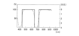
図7は撮像ユニット1に配置される励起光カットフィルター14の透過特性を示す図である。図7において、実線で示した曲線は、励起光カットフィルター14の入射面への入射角度が0°の光線に対する透過特性であり、図の左側の目盛りが適用される。図の左側の目盛りは透過率(単位:%)である。また、一点鎖線で示した曲線は、同様の光線に対する励起光カットフィルター14の阻止特性であり、図の右側の目盛りが適用される。図の右側の目盛りは光学濃度であって、フィルター14に入射する光の強度をI、フィルター14を透過した光の強度をI’としたときlog10(I/I’)で表される。横軸は波長(単位:nm)である。
FIG. 7 is a diagram showing the transmission characteristics of the excitation light cut
励起光カットフィルター14は、自家蛍光物質を励起するための狭帯域光Aおよび蛍光プローブを励起するための狭帯域光Bが撮像素子12の受光面に到達して蛍光画像のコントラストを低下させるのを防ぐために配置されている。そのため、狭帯域光AおよびBの波長範囲において、撮像ユニット1の光路中に配置される励起光カットフィルター14の光学濃度ODFとエタロン13の光学濃度ODEとの和が4以上となるように、励起光カットフィルター14の特性が決められている。これにより、撮像素子1の受光面での励起光の平均強度を蛍光のピーク強度に対して20分の1以下とすることができるので、良好なコントラストの蛍光画像を得ることができる。
The excitation light cut
エタロン13は、600nm未満の波長領域において、エアギャップを変化させても常に平均透過率が50%以上に保たれる第1の透過波長帯域と、600nm以上の波長領域において、エアギャップの変化とともに透過率がピークとなる波長が変化する第2の透過波長帯域とを有している。図8に、エタロン13の光学特性を説明する図を示す。図8(a)はエアギャップを形成する面の透過特性を表す図であり、横軸は波長(単位:nm)、縦軸は透過率(単位:%)を表している。図8(b)はエアギャップを変化させたときのエタロン13の透過特性を表す図であり、横軸は波長(単位:nm)、縦軸は透過率(単位:%)を表している。
The
エタロン13のエアギャップを形成する面の透過率は、600nm以上の波長領域で50%未満に設定され、600nm未満の波長領域で50%以上に設定されている。この結果、エタロン13は、第1の透過波長帯域ではエアギャップの変化にかかわらず安定して光を透過するとともに、第2の透過波長帯域で多光束干渉作用を利用した透過率ピーク波長の走査が可能であるように構成することができる。
The transmittance of the surface forming the air gap of the
次に、一度の観察で、病変組織の自家蛍光画像を取得する工程と、蛍光プローブが病変を特徴付ける物質と結合して発する蛍光の画像を取得する工程とを実行する場合における、本実施形態の蛍光内視鏡装置の基本動作を、図9を用いて説明する。
図9(a)は図6と同様に光源ユニット3が生成する励起光の波長範囲と、撮像ユニット1が検出する蛍光の波長範囲との関係を例示する概念図である。縦軸には励起光および蛍光の強度を表しており、単位は任意単位である。横軸は波長(単位:nm)を表している。図9(b)、(c)はエタロンの透過特性を示す図である。縦軸は透過率(単位:%)、横軸は波長(単位:nm)を表している。図9(d)、(e)、(f)は撮像素子の撮像面で受光される光の強度を示す図である。縦軸は光の強度を表しており、単位は任意単位である。横軸は波長(単位:nm)を表している。
Next, in the case where the process of acquiring the autofluorescence image of the diseased tissue and the process of acquiring the fluorescence image emitted by the fluorescent probe combined with the substance characterizing the lesion in one observation are performed. The basic operation of the fluorescence endoscope apparatus will be described with reference to FIG.
FIG. 9A is a conceptual diagram illustrating the relationship between the wavelength range of excitation light generated by the
図9(a)に示すように、自家蛍光物質を励起するための狭帯域光Aを一定時間、生体に照射することにより、コラーゲンやエラスチンから波長領域a1の蛍光を発生させると同時に、ポルフィリンから波長領域a2の蛍光を発生させ、また、蛍光プローブを励起するための狭帯域光Bを一定時間、生体に照射することにより、病変組織に結合した蛍光プローブから波長領域a3の蛍光を発生させる場合を考える。 As shown in FIG. 9 (a), by irradiating a living body with narrowband light A for exciting an autofluorescent substance for a certain period of time, fluorescence in the wavelength region a1 is generated from collagen and elastin, and at the same time from porphyrin. When generating fluorescence in the wavelength region a2 and generating fluorescence in the wavelength region a3 from the fluorescent probe bound to the diseased tissue by irradiating the living body with the narrowband light B for exciting the fluorescent probe for a certain period of time. think of.
蛍光内視鏡装置の光源ユニット3が狭帯域光Aを生成している期間には、エタロン13は、蛍光内視鏡装置の制御ユニット4から送信される制御信号により次の2つの状態に調整される。
状態1:波長領域a1と波長領域a2の光を透過する特性を有する状態(図9(b))
状態2:波長領域a1と波長領域a3の光を透過する特性を有する状態(図9(c))
エタロン13が上記状態1に設定されているときには、撮像素子12の撮像面では波長領域a1と波長領域a2の蛍光が受光される(図9(d))。また、エタロン13が上記状態2に設定されているときには、撮像素子12の撮像面では波長領域a1の蛍光のみが受光される(図9(e))。
During the period when the
State 1: State having a characteristic of transmitting light in the wavelength region a1 and wavelength region a2 (FIG. 9B)
State 2: a state having a characteristic of transmitting light in the wavelength region a1 and the wavelength region a3 (FIG. 9C)
When the
一方、蛍光内視鏡装置の光源ユニット3が狭帯域光Bを生成している期間には、エタロン13は、蛍光内視鏡装置の制御ユニット4から送信される制御信号により次の状態に調整される。
状態2:波長領域a1と波長領域a3の光を透過する特性を有する状態(図9(c))
このとき、撮像素子12の撮像面では波長領域a3の蛍光が受光される(図9(f))。
On the other hand, during the period in which the
State 2: a state having a characteristic of transmitting light in the wavelength region a1 and the wavelength region a3 (FIG. 9C)
At this time, fluorescence in the wavelength region a3 is received on the imaging surface of the imaging device 12 (FIG. 9 (f)).
図10は照明の状態と、エタロンの状態と、撮像ユニットが取得する蛍光画像信号との関係を時系列的に示すタイミングチャートである。蛍光内視鏡装置の照明ユニット2が狭帯域光Aを照射する第1の照明期間A1では、エタロン13は上記状態1に設定され、その結果、蛍光内視鏡装置の撮像ユニット12は波長領域a1と波長領域a2の蛍光成分を含んだ画像信号D1を取得する。画像信号D1は、照明が遮光されている期間S1中に読み出され、蛍光内視鏡装置の画像処理ユニット5のメモリ回路5aに蓄積される。また、照明ユニット2が狭帯域光Aを照射する第2の照明期間A2では、エタロン13は上記状態2に設定され、その結果、撮像ユニット1は波長領域a1の蛍光成分を含んだ画像信号D2を取得する。画像信号D2は、照明が遮光されている期間S2中に読み出され、画像処理ユニット5のメモリ回路5aに蓄積される。また、照明ユニット2が狭帯域光Bを照射する第3の照明期間B1では、エタロン13は上記状態2に設定され、その結果、撮像ユニット1は、波長領域a3の蛍光成分を含んだ画像信号D3を取得する。画像信号D3は、照明が遮光されている期間S3中に読み出され、画像処理ユニット5のメモリ回路5aに蓄積される。
FIG. 10 is a timing chart showing the relationship between the illumination state, the etalon state, and the fluorescence image signal acquired by the imaging unit in time series. In the first illumination period A1 in which the
そして、本実施形態の蛍光内視鏡装置では、上記の3つの照明状態を1サイクルとして、狭帯域光Aおよび狭帯域光Bの2種類の励起光が生体に対して繰り返し照射され、1サイクル中に取得された3種類の画像信号をもとにして、画像処理が行われる。まず、画像処理ユニット5の演算回路5bにより、3種類の画像信号のうち、狭帯域光Aが照明されている間に蓄積された画像信号D1と画像信号D2を用いて演算が行われる。図11は画像信号D1と画像信号D2を用いた演算を説明する概念図であり、縦軸は信号強度、横軸は波長を表している。画像信号D1は、図11(a)に示すように、波長領域a1と波長領域a2の蛍光成分を有しており、画像信号D2は、図11(b)に示すように波長領域a1の蛍光成分を有している。そこで、画像信号D1から画像信号D2を差し引くことで、図11(c)に示すように波長領域a2の蛍光成分のみを有する新たな画像信号E1を生成する。
In the fluorescence endoscope apparatus of the present embodiment, the above three illumination states are set as one cycle, and two types of excitation light of the narrow band light A and the narrow band light B are repeatedly irradiated to the living body, and one cycle. Image processing is performed based on the three types of image signals acquired therein. First, the
次に、3つの画像信号(画像信号D2、画像信号E1、画像信号D3)にTVモニター7の表示画面上にカラー表示を行うための色信号を割り当てる。例えば、R、G、Bの3色の信号を次の表3のように割り当てる場合、TVモニター7の表示画面上での蛍光画像は、生体組織の状態によって次の表4のように色分けされて表示される。
生体組織の粘膜下層に存在するコラーゲンやエラスチンの自家蛍光(以下、蛍光F01と略す)は粘膜層を通過して粘膜表面より放射される。同様に、生体内に存在する有機化合物であるポルフィリンの自家蛍光(以下、蛍光F02と略す)も、粘膜層を通過して粘膜表面より放射される。例えば、粘膜表層に炎症が起きると、粘膜表層における血流の量が増加して蛍光F01、F02の通り道が妨げられてしまい、粘膜表面より放射される蛍光F01、F02の強度は弱められる。このため、炎症が起きている組織から観測される蛍光F01、F02の強度は、その周辺の正常組織から観測される蛍光F01、F02の強度に比べて弱くなる。 Collagen and elastin autofluorescence (hereinafter abbreviated as fluorescence F01) present in the submucosal layer of living tissue passes through the mucosal layer and is emitted from the mucosal surface. Similarly, autofluorescence (hereinafter abbreviated as fluorescence F02) of porphyrin, which is an organic compound present in the living body, is emitted from the mucosal surface through the mucosal layer. For example, when inflammation occurs in the mucosal surface layer, the amount of blood flow in the mucosal surface layer increases, obstructing the passage of the fluorescence F01, F02, and the intensity of the fluorescence F01, F02 emitted from the mucosal surface is weakened. For this reason, the intensities of the fluorescences F01 and F02 observed from the inflamed tissue are weaker than the intensities of the fluorescences F01 and F02 observed from the surrounding normal tissues.
一方、粘膜組織に腫瘍が発生した場合にも、腫瘍組織の細胞核が肥大したり、細胞核周辺の血流量が増加して蛍光F01、F02の通り道が妨げられてしまい、粘膜表面より放射される蛍光F01、F02の強度は弱められる。ただし、ポルフィリンは腫瘍に多く蓄積される傾向があるので、実質的には腫瘍組織から粘膜表面に向けて放射される蛍光F02によって、腫瘍組織で妨げられる蛍光F02の強度が補われることになる。このため、腫瘍組織から観測される蛍光F01の強度は、その周辺の正常組織から観測される蛍光F01の強度に比べて弱くなるが、腫瘍組織から観測される蛍光F02の強度は、その周辺の正常組織から観測される蛍光F02の強度と同じかそれよりも強くなる。
また、蛍光プローブは腫瘍組織に由来する物質に結合して蛍光を発するので、腫瘍組織のみから蛍光が観測される。
On the other hand, even when a tumor occurs in the mucosal tissue, the cell nucleus of the tumor tissue is enlarged or the blood flow around the cell nucleus is increased to obstruct the passage of the fluorescence F01, F02, and the fluorescence emitted from the mucosal surface The strengths of F01 and F02 are weakened. However, since porphyrin tends to accumulate in the tumor, the fluorescence F02 emitted from the tumor tissue toward the mucosal surface substantially supplements the intensity of the fluorescence F02 blocked by the tumor tissue. For this reason, the intensity of the fluorescence F01 observed from the tumor tissue is weaker than the intensity of the fluorescence F01 observed from the surrounding normal tissue, but the intensity of the fluorescence F02 observed from the tumor tissue is around the periphery. It becomes the same or stronger than the intensity of the fluorescence F02 observed from the normal tissue.
Further, since the fluorescent probe binds to a substance derived from the tumor tissue and emits fluorescence, the fluorescence is observed only from the tumor tissue.
このような現象を踏まえ、3つの画像信号(画像信号D2、画像信号E1、画像信号D3)にそれぞれ異なる色信号を割り当てて、それらを合成表示させることで、TVモニター7の表示画面上では、上記表4に示すように、正常な組織は黄色、粘膜表層に炎症が起きている組織は灰色、腫瘍組織はマゼンダに色分けすることができる。
Based on such a phenomenon, by assigning different color signals to the three image signals (image signal D2, image signal E1, image signal D3) and displaying them in combination, on the display screen of the
早期癌など、生体組織の構造上の変化が少ない病変を内視鏡観察下で高精度に診断するためには、病変部とそれ以外の部位が明確に識別できるように、例えば表示画面上で色分けがなされているのが望ましい。そこで、上記のように病変組織に関する個別の情報を有する3つの画像信号を利用して表示画像の構築を行うことで、病変部とそれ以外の部位を明確に識別することができる。特に、何らかの原因で正常な組織に炎症が起こるなどして、従来の観察方法では病変組織との識別が困難であった部位を、病変組織とは異なる色調で表示させることができるので、病変組織のみを容易に特定することができ、診断の精度を飛躍的に向上させることができる。 In order to diagnose lesions with little structural change in living tissue such as early cancer with high accuracy under endoscopic observation, for example, on the display screen, the lesioned part and other parts can be clearly identified. It is desirable that they are color-coded. Therefore, by constructing the display image using the three image signals having the individual information regarding the diseased tissue as described above, it is possible to clearly identify the lesioned part and the other part. In particular, it is possible to display a site that was difficult to distinguish from a diseased tissue with conventional observation methods due to inflammation in normal tissue for some reason, etc. Can be easily identified, and the accuracy of diagnosis can be dramatically improved.
また、個別の蛍光画像には病変組織に関する固有の情報が含まれているので、上記のように擬似的に色分けされた画像に加えて、個別の蛍光画像も合わせて表示できるようにすれば、更に病変組織の診断を容易にすることができる。 In addition, since the individual fluorescent images contain unique information about the diseased tissue, in addition to the pseudo-color-coded images as described above, if individual fluorescent images can be displayed together, Furthermore, the diagnosis of a diseased tissue can be facilitated.
図12を用いて、本発明の実施例1にかかる蛍光内視鏡装置の構成を説明する。
本実施例の蛍光内視鏡装置は、光源ユニット3と、照明ユニット2と、撮像ユニット1を備えている。
撮像ユニット1と照明ユニット2は、内視鏡の挿入部先端101に配置されている。照明ユニット2は、ライトガイド31などの光学的な伝送手段により光源ユニット3と接続されており、光源ユニット3から供給される照明光を拡散作用を持つレンズを通して生体組織表面に照射するように構成されている。光源ユニット3は、図3を用いて説明したものと同様の構成であるので説明を省略する。撮像ユニット1は、対物光学系33と、撮像素子36と、対物光学系33の最も物体側の面から撮像素子36の撮像面までの間に、励起光カットフィルター34と、透過する光の波長帯域を変更可能な素子とを備えている。光の波長帯域を変更可能な素子としては、例えばエアギャップを調整することにより透過率ピーク波長を所望の値に変更することが可能なエタロンや、結晶の配列を電気的に調整することにより透過率ピーク波長を所望の値に変更することが可能な液晶チューナブルフィルターを用いることができる。本実施例の撮像ユニットにおいては、図8(b)に示すように、600nm未満の波長領域においてエアギャップを変化させても常に平均透過率が50%以上に保たれる第1の透過波長帯域と、600nm以上の波長領域においてエアギャップの変化とともに透過率ピーク波長が変化する第2の透過波長帯域とを有するエタロン35が配置されている。エタロン35は、内視鏡の操作部102に設けられたドライブ回路37に接続されている。ドライブ回路37は、接続コネクタ38を介して制御ユニット4と接続されており、制御ユニット4から送信される同期信号を受信してエタロン35の動作をコントロールする。ドライブ回路37は、撮像素子36と操作部102に設けられたスイッチ39にも接続されており、制御ユニット4との通信を中継する役割を有している。
The configuration of the fluorescence endoscope apparatus according to the first embodiment of the present invention will be described with reference to FIG.
The fluorescence endoscope apparatus according to the present embodiment includes a
The
制御ユニット4は、光源ユニット3が励起光を生成して照明ユニット2に供給するタイミングと、撮像ユニット1が生体組織表面からの蛍光像を撮像するタイミングと、エタロン35がエアギャップを変えるタイミングを制御する機能を有している。撮像ユニット1が取得した画像信号は、画像処理ユニット5によって蛍光画像に加工される。画像処理ユニット5には、画像信号をデータとして一時的に格納するメモリ回路5aと、メモリ回路5aに格納されたデータをもとにして画像処理に必要な演算を行う演算回路5bが備えられている。また、画像処理ユニット5にはDVDやHDDなどの外部記録装置6が接続されており、撮像ユニット1が取得した画像信号データや画像処理ユニット5によって加工された画像データを恒久的に記録して保存することができるようになっている。外部記録装置6に記録された画像信号データは、適宜、再生することが可能であり、画像処理ユニット5に取り込んで新たな画像処理を行うこともできる。画像処理ユニット5により加工された蛍光画像は、TVモニター7の表示画面上に表示される。
The
また、本実施例の蛍光内視鏡装置は、光源ユニット3の代わりに、波長の異なるコヒーレント光を発する複数の半導体素子を備えた別の光源ユニット8から、ライトガイド81を通して生体組織に励起光を供給することができるように構成されている。光源ユニット8は、半導体素子82と、半導体素子82が発したコヒーレント光をライトガイド81の入射端面に入射させる光学系83と、ライトガイド81の入射端面と半導体素子82の間に配置された光路合成用の光学素子84と、半導体素子82の発光状態を制御するドライブ回路85を備えている。ドライブ回路85は、制御ユニット4に接続されて制御ユニット4から送信される同期信号を受信し、撮像ユニット1が生体組織表面から蛍光像を撮像するタイミングと、エタロン35がエアギャップを変えるタイミングと、半導体82がコヒーレント光を生成してライトガイド81に供給するタイミングとが同期するように半導体素子82の発光状態を切換える。半導体素子82を発したコヒーレント光は、内視鏡の処置具挿通口を通して内視鏡の挿入部先端まで導入されたライトガイド81により生体組織に照射される。なお、ライトガイド81の出射端面には、光を拡散する光学素子を配置することも可能である。また、半導体素子82の発光状態を一定に保ち、半導体素子82を発したコヒーレント光を周期的に遮光することで、ライトガイド81に対して励起光を供給する期間を制御することもできる。この場合は、図13に示すように、半導体素子82の前方の光路を周期的に遮るチョッパー86が配置される。チョッパー86には、光束を横切り始める状態と光束を横切り終わる状態とをそれぞれ検知するセンサーが備えられており、センサーが検知した信号はドライブ回路85を通して制御ユニット4に送信され、撮像ユニット1から画像信号を読み出すタイミングと遮光期間を同期させる信号として利用される。
In addition, the fluorescence endoscope apparatus according to the present embodiment provides excitation light to living tissue through a
次に、本実施例の蛍光内視鏡装置の基本動作を、図14および図15を用いて説明する。
図14(a)は図6と同様に本実施例の蛍光内視鏡装置で用いる励起光及び励起される蛍光を例示する概念図である。縦軸には励起光および蛍光の強度を表しており、単位は任意単位である。横軸は波長(単位:nm)を表している。図14(b)、(c)、(d)は、エタロンの透過特性を示す図である。縦軸は透過率(単位:%)、横軸は波長(単位:nm)を表している。図14(e)、(f)、(g)は、撮像素子の撮像面で受光される光の強度を示す図である。縦軸は光の強度を表しており、単位は任意単位である。横軸は波長(単位:nm)を表している。図14(h)は励起光カットフィルターの透過特性を示す図である。図14(h)において、実線で示した曲線は、励起光カットフィルターの入射面への入射角度が0°の光線に対する透過特性であり、図の左側の目盛りが適用される。図の左側の目盛りは、透過率(単位:%)である。図14(h)において、一点鎖線で示した曲線は、同様の光線に対する励起光カットフィルターの阻止特性であり、図の右側の目盛りが適用される。図の右側の目盛りは、光学濃度であって、フィルターに入射する光の強度をI、フィルターを透過した光の強度をI’としたときlog10(I/I’)で表される。横軸は波長(単位:nm)である。また、図15は照明の状態と、エタロンの状態と、撮像ユニットが取得する蛍光画像信号との関係を時系列的に示すタイミングチャートである。
Next, the basic operation of the fluorescence endoscope apparatus according to the present embodiment will be described with reference to FIGS.
FIG. 14A is a conceptual diagram illustrating excitation light and excited fluorescence used in the fluorescence endoscope apparatus of the present embodiment, similarly to FIG. The vertical axis represents the intensity of excitation light and fluorescence, and the unit is an arbitrary unit. The horizontal axis represents the wavelength (unit: nm). 14B, 14C, and 14D are diagrams showing the transmission characteristics of etalon. The vertical axis represents transmittance (unit:%), and the horizontal axis represents wavelength (unit: nm). FIGS. 14E, 14 </ b> F, and 14 </ b> G are diagrams illustrating the intensity of light received by the imaging surface of the imaging element. The vertical axis represents the light intensity, and the unit is an arbitrary unit. The horizontal axis represents the wavelength (unit: nm). FIG. 14H is a diagram showing the transmission characteristics of the excitation light cut filter. In FIG. 14 (h), the curve indicated by the solid line is the transmission characteristic for a light beam whose incident angle to the incident surface of the excitation light cut filter is 0 °, and the scale on the left side of the figure is applied. The scale on the left side of the figure is the transmittance (unit:%). In FIG. 14H, the curve indicated by the alternate long and short dash line is the blocking characteristic of the excitation light cut filter with respect to similar light rays, and the scale on the right side of the figure is applied. The scale on the right side of the figure is the optical density, and is expressed as log 10 (I / I ′) where I is the intensity of light incident on the filter and I ′ is the intensity of light transmitted through the filter. The horizontal axis is the wavelength (unit: nm). FIG. 15 is a timing chart showing the relationship between the illumination state, the etalon state, and the fluorescence image signal acquired by the imaging unit in time series.
図14(a)に示すように、本実施例の蛍光内視鏡装置では、生体組織に対して2つの異なる励起光を照射して、それぞれ波長の異なる3種類の蛍光画像を取得することができる。405nmをピークとする強度分布を有するコヒーレント光Aは、コラーゲンやエラスチンを励起して波長領域a1の自家蛍光を発生させると同時に、ポルフィリンを励起して波長領域a2の自家蛍光を発生させる。波長領域a1は420nm〜580nm、波長領域a2は610nm〜640nmである。また、660nmをピークとする強度分布を有するコヒーレント光Bは、病変組織に結合した蛍光プローブを励起して波長領域a3の蛍光を発生させる。波長領域a3は710nm〜740nmである。撮像ユニットに配置されている励起光カットフィルター34の特性は、420nm〜640nmでの平均透過率および710nm〜740nmでの平均透過率が70%以上であり、405nmおよび660nmにおける光学濃度が4以上である(図14(h))。励起光カットフィルター34によってコヒーレント光AおよびBは十分に遮断される。
As shown in FIG. 14A, in the fluorescence endoscope apparatus of the present embodiment, two different excitation lights are irradiated to a living tissue, and three types of fluorescence images having different wavelengths can be obtained. it can. The coherent light A having an intensity distribution with a peak at 405 nm excites collagen and elastin to generate autofluorescence in the wavelength region a1, and simultaneously excites porphyrin to generate autofluorescence in the wavelength region a2. The wavelength region a1 is 420 nm to 580 nm, and the wavelength region a2 is 610 nm to 640 nm. Further, the coherent light B having an intensity distribution having a peak at 660 nm excites a fluorescent probe bonded to a diseased tissue to generate fluorescence in the wavelength region a3. The wavelength region a3 is 710 nm to 740 nm. The excitation light cut
内視鏡の操作部102に設けられたスイッチ39を押すなどの動作により、内視鏡の操作者から蛍光内視鏡装置に対して蛍光画像の取得を開始するための指示が出されると、制御ユニット4は、光源ユニット3と撮像ユニット1とエタロン35のドライブ回路37に対して同期信号を送信する。エタロン35は、ドライブ回路37からの制御電流によりエアギャップを変化させ、少なくとも透過特性の異なる3つの状態に設定される。光源ユニット3がコヒーレント光Aを生成している期間には、エタロン35は次の2つの状態に順次設定される。
状態1:波長領域a1の光のみを透過する特性を有する状態(図14(b))
状態2:波長領域a1と波長領域a2の光を透過する特性を有する状態(図14(c))
上記状態1においては、エタロン35のエアギャップが3つの状態の中で最も長くなるように設定される。このとき、エタロン35の第2の透過波長帯域は、透過率ピークが740nmよりも長波長側にあって、透過率ピークに対する半値全幅が60nmである。また、上記状態2においては、エタロン35のエアギャップが3つの状態の中で最も短くなるように設定される。このとき、エタロン35の第2の透過波長帯域は、透過率ピークが610nm〜640nmの波長範囲にあって、透過率ピークに対する半値全幅が60nmである。エタロン35が上記状態1に設定されているときには、撮像素子36の撮像面では波長領域a1の光のみが受光される(図14(e))。また、エタロン35が上記状態2に設定されているときには、撮像素子36の撮像面では波長領域a1と波長領域a2の蛍光が受光される(図14(f))。
When an instruction for starting acquisition of a fluorescence image is issued from the operator of the endoscope to the fluorescence endoscope apparatus by an operation such as pressing a
State 1: State having a characteristic of transmitting only light in the wavelength region a1 (FIG. 14B)
State 2: State having a characteristic of transmitting light in the wavelength region a1 and wavelength region a2 (FIG. 14C)
In the
一方、光源ユニット3がコヒーレント光Bを生成している期間には、エタロン35は、次の状態に設定される。
状態3:波長領域a1と波長領域a3の光を透過する特性を有する状態(図14(d))
上記状態3においては、エタロン35のエアギャップが上記状態2よりも大きく上記状態3よりも小さくなるように設定される。このとき、エタロン35の第2の透過波長帯域は、透過率ピークが710nm〜740nmの波長範囲にあって、透過率ピークに対する半値全幅が60nmである。エタロン35が上記状態3に設定されているときには、撮像素子36の撮像面では波長領域a3の蛍光が受光される(図14(g))。
On the other hand, during the period when the
State 3: State having a characteristic of transmitting light in the wavelength region a1 and wavelength region a3 (FIG. 14D)
In the
図15のタイミングチャートに示すように、照明ユニット2がコヒーレント光Aを照射する第1の照明期間A1では、エタロン35は、上記状態1に設定される。その結果、撮像ユニット1は波長領域a1の蛍光画像信号D1を取得する。画像信号D1は、照明が遮光されている期間S1中に読み出され、画像処理ユニット5のメモリ回路5aに蓄積される。また、照明ユニット2がコヒーレント光Aを照射する第2の照明期間A2では、エタロン35は、上記状態2に設定される。その結果、撮像ユニット1は、波長領域a1と波長領域a2の蛍光成分を含んだ蛍光画像信号D2を取得する。画像信号D2は、照明が遮光されている期間S2中に読み出され、画像処理ユニット5のメモリ回路5aに蓄積される。また、照明ユニット2がコヒーレント光Bを照射する第3の照明期間B1では、エタロン35は、上記状態3に設定される。その結果、撮像ユニット1は、波長領域a3の蛍光画像信号D3を取得する。画像信号D3は、照明が遮光されている期間S3中に読み出され、画像処理ユニット5のメモリ回路5aに蓄積される。
As shown in the timing chart of FIG. 15, the
そして、本実施例の蛍光内視鏡装置では、上記の3つの照明状態を1サイクルとして、コヒーレント光Aおよびコヒーレント光Bの2種類の励起光が生体に対して繰り返し照射され、1サイクル中に取得された3種類の画像信号をもとにして、画像処理が行われる。画像処理ユニット5による画像処理の手順は、上述した手順と同じであるので説明を省略する。
図16は本実施例の蛍光内視鏡装置がTVモニター7の表示画面上に表示可能な蛍光画像の種類を模式的に示す図である。図16(a)は画像信号D2を基にして作成されたコラーゲンやエラスチンの自家蛍光画像、図16(b)は画像信号E1を基にして作成されたポルフィリンの自家蛍光画像、図16(c)は画像信号D3を基にして作成された病変組織と結合した蛍光プローブからの蛍光画像、図16(d)は3つの画像信号を基にして作成された擬似カラー画像である。擬似カラー画像では、正常部位と、正常組織の表層が炎症を起こしている部位と、病変部位とが擬似的に色分けされて表示される。画像処理ユニット5は、これら4種類の画像をTVモニター7の表示画面上に同じ大きさで並べて表示させたり、各画像ごとに表示倍率を変えて表示させることができる。
このように、本実施例の蛍光内視鏡装置では、病変組織に関する個別の情報を含んだ蛍光画像と、擬似カラー画像とを比較しながら診断を行えるようにしたので、診断の精度を向上させることができる。
In the fluorescence endoscope apparatus of the present embodiment, the above three illumination states are set as one cycle, and two types of excitation light of the coherent light A and the coherent light B are repeatedly irradiated to the living body. Image processing is performed based on the acquired three types of image signals. Since the procedure of image processing by the
FIG. 16 is a diagram schematically showing the types of fluorescent images that can be displayed on the display screen of the
As described above, in the fluorescence endoscope apparatus according to the present embodiment, the diagnosis can be performed while comparing the fluorescence image including the individual information regarding the diseased tissue with the pseudo color image, thereby improving the accuracy of the diagnosis. be able to.
なお、本実施例の蛍光内視鏡装置に用いる撮像ユニット1は、対物光学系33と、撮像素子36と、対物光学系33の最も物体側の面から撮像素子36の撮像面までの間に配置された励起光カットフィルター34とエタロン35により構成されているが、この構成に限定されるものではなく、例えば、図17に示すように、挿入部先端101に配置された対物光学系50によって取得した被写体の像をイメージファイバ51などの光学的な像伝送手段を用いて操作部102まで伝送し、操作部102に配置された結像光学系52により撮像素子55の撮像面に結像させるように構成された内視鏡を用いることもできる。この場合、エタロン54は、結像光学系52と撮像素子55との間に配置され、励起光カットフィルター53は対物光学系50の最も物体側の面からエタロン54の光入射面までの間に配置される。また、エタロン54の動作は、操作部102に配置されたドライブ回路56により制御される。
このような構成の内視鏡は、挿入部先端101を細径にすることができるので、マウスなどの小動物を傷つけることなく消化器の生体組織を観察するのに適している。
The
The endoscope having such a configuration is suitable for observing the living tissue of the digestive organ without damaging a small animal such as a mouse because the
また、本実施例の蛍光内視鏡装置に用いる撮像ユニット1は、図18〜20に示すような構成をとることもできる。図18は本実施例の内視鏡装置に用いる撮像ユニット1の構成例を示す図であり、図19は撮像ユニット1に用いる複数種類の光学フィルター40を構成する各光学フィルターの配置例を示す図であり、図20は複数種類の光学フィルター40を構成する各種類ごとの光学フィルターの透過率特性を示す図である。すなわち、エタロンに代えて、撮像素子36の撮像面の直前に、それぞれ異なる波長帯域の光を透過する複数種類の光学フィルター40を、個々の光学フィルターが撮像素子36の画素と重なるように並べて構成し、同じ透過特性を持つ光学フィルターが配置された画素ごとに蛍光像を撮像すれば、複数の蛍光画像を個別に取得することができる。
Moreover, the
複数種類の光学フィルター40には、400nm〜800nmの波長範囲において異なる透過特性を有する次の3つの光学フィルターが用いられている。
(1)420nm〜580nmの波長範囲で平均透過率が50%以上であり、その他の波長範囲での平均透過率が5%以下である光学フィルターOF1(図20(a))
(2)610nm〜640nmの波長範囲で平均透過率が50%以上であり、その他の波長範囲での平均透過率が5%以下である光学フィルターOF2(図20(b))
(3)710nm〜740nmの波長範囲で平均透過率が50%以上であり、その他の波長範囲での平均透過率が5%以下である光学フィルターOF3(図20(c))
ただし、前記光学フィルターの平均透過率は、所定の波長範囲における透過率Tの平均値である。前記光学フィルターの透過率Tは、400nm〜800nmの波長範囲に属する任意波長λの光の光学フィルターの入射面への入射光量をIL1、光学フィルターの出射面からの波長λの光の出射光量をIL2としたとき、T=(IL2/IL1)×100で表される。
As the plural types of
(1) Optical filter OF1 having an average transmittance of 50% or more in the wavelength range of 420 nm to 580 nm and an average transmittance of 5% or less in the other wavelength ranges (FIG. 20A)
(2) Optical filter OF2 having an average transmittance of 50% or more in the wavelength range of 610 nm to 640 nm and an average transmittance of 5% or less in the other wavelength ranges (FIG. 20B)
(3) Optical filter OF3 having an average transmittance of 50% or more in the wavelength range of 710 nm to 740 nm and an average transmittance of 5% or less in other wavelength ranges (FIG. 20 (c)).
However, the average transmittance of the optical filter is an average value of the transmittance T in a predetermined wavelength range. The transmittance T of the optical filter is the amount of light incident on the incident surface of the optical filter of light having an arbitrary wavelength λ belonging to the wavelength range of 400 nm to 800 nm, IL1, and the amount of emitted light of light of wavelength λ from the output surface of the optical filter. When expressed as IL2, T = (IL2 / IL1) × 100.
図19に示す例では、撮像素子36の画素列(1ライン)ごとに光学フィルターOF1、OF2、OF3が配置されているので、同じ透過特性を持つ光学フィルターが配置された画素列ごとに蛍光像を撮像すれば、複数の蛍光画像を個別に取得することができる。このような構成の場合、撮像信号の逐次読み出しが可能であり、照明期間中に撮像信号を読み出すための遮光期間を設ける必要が無い。このため、微弱な蛍光でも明るく撮像することが可能である。また、異なる波長帯域の蛍光を一度に分離することができるので、コヒーレント光Aとコヒーレント光Bを同時に照射することができ、光源ユニット8の構成を簡略化することが可能である。また、複数の蛍光画像を個別に取得することができるので、画像処理ユニット5における演算処理を省略することができる。
In the example shown in FIG. 19, since the optical filters OF1, OF2, and OF3 are arranged for each pixel column (one line) of the
図21を用いて、本発明の実施例2にかかる蛍光内視鏡装置の構成を説明する。
撮像ユニット1、照明ユニット2、光源ユニット3の基本構成は、実施例1で説明した構成と同様であるので説明を省略する。
制御ユニット4には、光源ユニット3が励起光を生成して照明ユニット2に供給するタイミングを基にして、撮像ユニット1が生体組織表面からの蛍光像を撮像するタイミングと、エタロン63がエアギャップを変えるタイミングを制御するタイミング制御回路4aと、エタロン63の動作を制御するドライブ回路4bと、エタロン63の動作制御に必要な情報を記録したメモリ回路4cが備えられている。内視鏡と制御ユニット4を接続する接続コネクタ65には、撮像ユニット1の製造番号やエタロンの種類などの基本情報を記録したメモリチップが備えられており、接続コネクタ65が制御ユニット4に接続されると、接続コネクタ65側のメモリチップから制御ユニット4に撮像ユニット1の基本情報が読み込まれるようになっている。エタロン63のドライブ回路4bは、読み取った撮像ユニット1の基本情報と制御ユニット4側のメモリ回路4cに格納されているエタロンの動作制御に必要な情報とを照合して、接続された撮像ユニット1に最も適したエタロン63の動作環境を自動的に設定する。撮像ユニット1が取得した画像信号は、画像処理ユニット5によって蛍光画像に加工され、TVモニター7に表示される。画像処理回路5、外部記録装置6、TVモニター7等の構成も実施例1の構成と同様であるので説明を省略する。
The configuration of the fluorescence endoscope apparatus according to the second embodiment of the present invention will be described with reference to FIG.
Since the basic configuration of the
Based on the timing at which the
次に、本実施例の蛍光内視鏡装置の基本動作を、図22および図23を用いて説明する。
図22(a)は図6と同様に光源ユニット3が生成する励起光の波長範囲と、撮像ユニット1が検出する蛍光の波長範囲との関係を例示する概念図である。縦軸には励起光および蛍光の強度を表しており、単位は任意単位である。横軸は波長(単位:nm)を表している。図22(b)、(c)、(d)、(e)はエタロン63の透過特性を示す図である。図22(b)、(c)、(d)、(e)において、実線で示した曲線は、エタロンの光入射面への入射角度が0°の光線に対する透過特性であり、図の左側の目盛りが適用される。図の左側の目盛りは、透過率(単位:%)である。一点鎖線で示した曲線は、同様の光線に対するエタロンの阻止特性であり、図の右側の目盛りが適用される。図の右側の目盛りは、光学濃度であって、エタロンに入射する光の強度をI、エタロンを透過した光の強度をI’としたときlog10(I/I’)で表される。横軸は波長(単位:nm)である。図22(f)、(g)、(h)、(i)は撮像素子64の撮像面で受光される光の強度を示す図である。縦軸は光の強度を表しており、単位は任意単位である。横軸は波長(単位:nm)を表している。図22(j)は励起光カットフィルター62の透過特性を示す図である。図22(j)において、実線で示した曲線は、励起光カットフィルター62の入射面への入射角度が0°の光線に対する透過特性であり、図の左側の目盛りが適用される。図の左側の目盛りは、透過率(単位:%)である。一点鎖線で示した曲線は、同様の光線に対する励起光カットフィルター62の阻止特性であり、図の右側の目盛りが適用される。図の右側の目盛りは、光学濃度であって、励起光カットフィルター62に入射する光の強度をI、励起光カットフィルター62を透過した光の強度をI’としたときlog10(I/I’)で表される。横軸は波長(単位:nm)である。また、図23は照明の状態と、エタロンの状態と、撮像ユニットが取得する蛍光画像信号との関係を時系列的に示すタイミングチャートである。
Next, the basic operation of the fluorescence endoscope apparatus according to the present embodiment will be described with reference to FIGS.
FIG. 22A is a conceptual diagram illustrating the relationship between the wavelength range of excitation light generated by the
図22(a)に示すように、本実施例の蛍光内視鏡装置では、生体組織に対して2つの異なる励起光を照射して、それぞれ波長の異なる4種類の蛍光画像を取得することができる。400nm〜430nmの波長範囲内の光で構成される励起光Aは、コラーゲンやエラスチンを励起して波長領域a1の自家蛍光を発生させると同時に、ポルフィリンを励起して波長領域a2の自家蛍光を発生させる。波長領域a1は、440nm〜580nm、波長領域a2は、610nm〜640nmである。また、680nm〜700nmの波長範囲内の光で構成される励起光Bは、病変組織に由来する物質k1に結合した蛍光プローブを励起して波長領域a3の蛍光を発生させると同時に、病変組織に由来する別の物質k2に結合した蛍光プローブを励起して波長領域a4の蛍光を発生させる。波長領域a3は、710nm〜740nmであり、波長領域a4は、770nm〜800nmである。撮像ユニット1に配置されている励起光カットフィルター62の特性は、440nm〜640nmでの平均透過率および710nm〜800nmでの平均透過率が70%以上であり、400nm〜430nmおよび680nm〜700nmにおける光学濃度が4以上である(図22(j))。励起光カットフィルター62によって励起光Aおよび励起光Bは、十分に遮断される。
As shown in FIG. 22 (a), in the fluorescence endoscope apparatus according to the present embodiment, two different excitation lights are irradiated to a living tissue, and four types of fluorescence images having different wavelengths can be acquired. it can. Excitation light A composed of light within a wavelength range of 400 nm to 430 nm excites collagen and elastin to generate autofluorescence in the wavelength region a1 and simultaneously excites porphyrin to generate autofluorescence in the wavelength region a2. Let The wavelength region a1 is 440 nm to 580 nm, and the wavelength region a2 is 610 nm to 640 nm. The excitation light B composed of light in the wavelength range of 680 nm to 700 nm excites the fluorescent probe bound to the substance k1 derived from the lesion tissue to generate fluorescence in the wavelength region a3, and at the same time, to the lesion tissue. A fluorescent probe bonded to another derived substance k2 is excited to generate fluorescence in the wavelength region a4. The wavelength region a3 is 710 nm to 740 nm, and the wavelength region a4 is 770 nm to 800 nm. The characteristics of the excitation light cut
内視鏡の操作者から蛍光内視鏡装置に対して蛍光画像の取得を開始するための指示が出されると、制御ユニット4は、光源ユニット3を励起光生成モードに切換える信号を送信する。光源ユニット3がこの信号を受信すると、回転ディスク24の回転軸が所定の位置まで移動して一定速度で回転する。図24に、回転ディスク24に配置される光学フィルターのレイアウトを示す。光路中には、蛍光画像観察用の光学フィルター(e)および光学フィルター(f)が繰り返し挿入される。光学フィルター(e)は400nm〜430nmの波長範囲で透過率Tが50%以上となる透過特性を有しており、光学フィルター(f)は680nm〜700nmの波長範囲で透過率Tが50%以上となる透過特性を有している。その結果、照明ユニットが400nm〜430nmの波長範囲の励起光Aを照射する第1の照明期間A1および第2の照明期間A2と、680nm〜700nmの波長範囲の励起光Bを照射する第3の照明期間B1の3つの照明期間が遮光期間をはさんで繰り返される。光源ユニット3には、1つの光学フィルターが光束を横切り終わる状態と、その次の光学フィルターが光束を横切り始める状態を検知するセンサーユニット25が備えられている(図3)。センサーユニット25が検知した信号は制御ユニット4に送信され、撮像ユニット1から画像信号を読み出すタイミングやエタロン63がエアギャップを変えるタイミングを照明光が遮光されている期間と同期させる信号として利用される。
When an instruction for starting acquisition of a fluorescence image is issued from the endoscope operator to the fluorescence endoscope apparatus, the
エタロン63は、ドライブ回路4bからの制御電流によりエアギャップを変化させ、少なくとも透過特性の異なる4つの状態に設定される。光源ユニット3が励起光Aを生成している期間には、エタロン63は、次の2つの状態に順次設定される。
状態1:波長領域a1の光のみを透過する特性を有する状態(図22(e))
状態2:波長領域a1と波長領域a2の光を透過する特性を有する状態(図22(d))
上記状態1においては、エタロン63のエアギャップが4つの状態の中で最も長くなるように設定される。このとき、エタロン63の第2の透過波長帯域は、透過率ピークが800nmよりも長波長側にあって、透過率ピークに対する半値全幅が30nmである。また、上記状態2においては、エタロン63のエアギャップが4つの状態の中で最も短くなるように設定される。このとき、エタロン63の第2の透過波長帯域は、透過率ピークが610nm〜640nmの波長範囲にあって、透過率ピークに対する半値全幅が30nmである。エタロン63が上記状態1に設定されているときには、撮像素子64の撮像面では波長領域a1の蛍光のみが受光される(図22(i))。また、エタロン63が上記状態2に設定されているときには、撮像素子64の撮像面では波長領域a1と波長領域a2の蛍光が受光される(図22(h))。
The
State 1: State having a characteristic of transmitting only light in the wavelength region a1 (FIG. 22E)
State 2: State having a characteristic of transmitting light in the wavelength region a1 and the wavelength region a2 (FIG. 22D)
In the
一方、光源ユニット3が励起光Bを生成している期間には、エタロン63は、次の2つの状態に設定される。
状態3:波長領域a1と波長領域a3の光を透過する特性を有する状態(図22(c))
状態4:波長領域a1と波長領域a4の光を透過する特性を有する状態(図22(b))
上記状態3および上記状態4においては、エタロン63のエアギャップが上記状態2よりも大きく上記状態1よりも小さくなるように設定される。ただし、上記状態3におけるエアギャップは上記状態4におけるエアギャップより小さい。エタロン63が上記状態3に設定されているときには、エタロン63の第2の透過波長帯域は、透過率ピークが710nm〜740nmの波長範囲にあって、透過率ピークに対する半値全幅が30nmである。このとき、撮像素子64の撮像面では、波長領域a3の蛍光が受光される(図22(g))。また、エタロン63が上記状態4に設定されているときには、エタロン63の第2の透過波長帯域は、透過率ピークが770nm〜800nmの波長範囲にあって、透過率ピークに対する半値全幅が30nmである。このとき、撮像素子64の撮像面では、波長領域a4の蛍光が受光される(図22(f))。
On the other hand, during the period when the
State 3: a state having a characteristic of transmitting light in the wavelength region a1 and the wavelength region a3 (FIG. 22C)
State 4: State having characteristics of transmitting light in the wavelength region a1 and the wavelength region a4 (FIG. 22B)
In the
図23のタイミングチャートに示すように、照明ユニット2が励起光Aを照射する第1の照明期間A1から照明ユニット2が励起光Bを照射する第3の照明期間B1までを1サイクルとすると、本実施例の蛍光内視鏡装置では、2サイクルする間に画像処理に必要な画像データが取得される。最初の1サイクルでは、照明ユニット2が励起光Aを照射する第1の照明期間A1の間、エタロン63は上記状態1に設定される。その結果、撮像ユニット1は、波長領域a1の蛍光画像信号D1を取得する。画像信号D1は、照明が遮光されている期間S1中に読み出され、画像処理ユニット5のメモリ回路5aに蓄積される。また、照明ユニット2が励起光Aを照射する第2の照明期間A2では、エタロン63は、上記状態2に設定される。その結果、撮像ユニット1は、波長領域a1と波長領域a2の蛍光成分を含んだ蛍光画像信号D2を取得する。画像信号D2は、照明が遮光されている期間S2中に読み出され、画像処理ユニット5のメモリ回路5aに蓄積される。また、照明ユニット2が励起光Bを照射する第3の照明期間B1では、エタロン63は、上記状態3に設定される。その結果、撮像ユニット1は、波長領域a3の蛍光画像信号D3を取得する。画像信号D3は、照明が遮光されている期間S3中に読み出され、画像処理ユニット5のメモリ回路5aに蓄積される。
As shown in the timing chart of FIG. 23, if one cycle is from the first illumination period A1 in which the
次の1サイクルでは、照明ユニット2が励起光Aを照射する第1の照明期間A1の間、エタロン63は、もう一度、上記状態1に設定される。その結果、撮像ユニット1は、波長領域a1の蛍光画像信号D4を取得する。画像信号D4は、照明が遮光されている期間S1中に読み出され、画像処理ユニット5のメモリ回路5aに蓄積される。また、照明ユニット2が励起光Aを照射する第2の照明期間A2では、エタロン63は、上記状態2に設定される。その結果、撮像ユニット1は、波長領域a1と波長領域a2の蛍光成分を含んだ蛍光画像信号D5を取得する。画像信号D5は、照明が遮光されている期間S2中に読み出され、画像処理ユニット5のメモリ回路5aに蓄積される。また、照明ユニット2が励起光Bを照射する第3の照明期間B1では、エタロン63は、上記状態4に設定される。その結果、撮像ユニット1は、波長領域a4の蛍光画像信号D6を取得する。画像信号D6は、照明が遮光されている期間S3中に読み出され、画像処理ユニット5のメモリ回路5aに蓄積される。
In the next one cycle, during the first illumination period A1 in which the
そして、本実施例の蛍光内視鏡装置では、上記の2サイクル中に取得された画像信号をもとにして、画像処理が行われる。画像処理ユニット5による画像処理の手順は、上述した手順と同じであるので説明を省略する。
図25は本実施例の蛍光内視鏡装置がTVモニター7の表示画面上に表示可能な蛍光画像の種類を模式的に示す図である。図25(a)は上述した最初の1サイクルの間に取得された3種類の画像信号を基にして作成された擬似カラー画像である。擬似カラー画像では、正常部位と、正常組織の表層が炎症を起こしている部位と、病変部位とが擬似的に色分けされて表示される。図25(b)は次の1サイクルの間に取得された3種類の画像信号を基にして作成された擬似カラー画像である。擬似カラー画像では、正常部位と、正常組織の表層が炎症を起こしている部位と、病変部位とが擬似的に色分けされて表示される。図25(c)は図25(a)に示す画像と図25(b)に示す画像とを合成表示させたものであり、図25(a)における病変部位の表示範囲と図25(b)における病変部位の表示範囲が重なる場合には、その部分を強調して表示するようにしたものである。
図25(a)に示す画像は、病変組織に由来する物質k1に関する情報を含む画像であり、図25(b)に示す画像は、病変組織に由来する別の物質k2に関する情報を含む画像である。そこで、図25(c)に示すように、これらの画像を合成表示することにより、病変組織に関する情報量を増加させ、病変組織を特定するにあたってより信頼性の高い画像を提供することができる。
このように、本実施例の蛍光内視鏡装置では、病変組織に由来する複数種類の検出対象物質(例えば、病変組織が悪性化するときに関与する物質や、病変組織が活発に増殖するときに関与する物質など)をそれぞれ選択的に捉えて結合する蛍光プローブを利用して病変組織の診断に有用な蛍光画像を構築したので、早期癌など、生体組織の構造上の変化が少ない病変でも高精度に診断することができる。
In the fluorescence endoscope apparatus according to the present embodiment, image processing is performed based on the image signal acquired during the above two cycles. Since the procedure of image processing by the
FIG. 25 is a diagram schematically showing the types of fluorescent images that can be displayed on the display screen of the
The image shown in FIG. 25A is an image including information related to the substance k1 derived from the diseased tissue, and the image illustrated in FIG. 25B is an image including information related to another substance k2 derived from the diseased tissue. is there. Therefore, as shown in FIG. 25C, by combining and displaying these images, it is possible to increase the amount of information related to the diseased tissue and provide a more reliable image in specifying the diseased tissue.
As described above, in the fluorescence endoscope apparatus according to the present embodiment, a plurality of types of detection target substances derived from a diseased tissue (for example, substances involved when a diseased tissue becomes malignant, or when a diseased tissue proliferates actively). We have constructed a fluorescent image that is useful for diagnosing diseased tissues using fluorescent probes that selectively capture and bind each substance involved in Diagnosis can be made with high accuracy.
なお、本実施例の蛍光内視鏡装置においても、エタロン63に代えて撮像素子64の撮像面の直前に、それぞれ異なる波長帯域の光を透過する複数種類の光学フィルターを、個々の光学フィルターが撮像素子の画素と重なるように並べて構成することができる。そして、同じ透過特性を持つ光学フィルターが配置された画素ごとに蛍光像を撮像すれば、複数の蛍光画像を個別に取得することができる。
複数種類の光学フィルターには、400nm〜800nmの波長範囲において異なる透過特性を有する次の4つの光学フィルターが用いられている。
(1)420nm〜580nmの波長範囲で透過率Tが50%以上であり、その他の波長範囲での平均透過率が5%以下である光学フィルター
(2)610nm〜640nmの波長範囲で透過率Tが50%以上であり、その他の波長範囲での平均透過率が5%以下である光学フィルター
(3)710nm〜740nmの波長範囲で透過率Tが50%以上であり、その他の波長範囲での平均透過率が5%以下である光学フィルター
(4)770nm〜800nmの波長範囲で透過率Tが50%以上であり、その他の波長範囲での平均透過率が5%以下である光学フィルター
ただし、前記光学フィルターの平均透過率は、所定の波長範囲における光学フィルターの透過率Tの平均値である。前記光学フィルターの透過率Tは、400nm〜800nmの波長範囲に属する任意波長λの光の光学フィルターの入射面への入射光量をIL1、光学フィルターの出射面からの波長λの光の出射光量をIL2としたとき、T=(IL2/IL1)×100で表される。
Also in the fluorescence endoscope apparatus of the present embodiment, a plurality of types of optical filters that transmit light of different wavelength bands are provided in front of the imaging surface of the
The following four optical filters having different transmission characteristics in the wavelength range of 400 nm to 800 nm are used as the plurality of types of optical filters.
(1) An optical filter having a transmittance T of 50% or more in the wavelength range of 420 nm to 580 nm and an average transmittance of 5% or less in other wavelength ranges.
(2) An optical filter having a transmittance T of 50% or more in the wavelength range of 610 nm to 640 nm and an average transmittance of 5% or less in other wavelength ranges.
(3) An optical filter having a transmittance T of 50% or more in the wavelength range of 710 nm to 740 nm and an average transmittance of 5% or less in other wavelength ranges.
(4) An optical filter having a transmittance T of 50% or more in a wavelength range of 770 nm to 800 nm and an average transmittance in other wavelength ranges of 5% or less. However, the average transmittance of the optical filter is a predetermined value. It is the average value of the transmittance T of the optical filter in the wavelength range. The transmittance T of the optical filter is the amount of light incident on the incident surface of the optical filter of light having an arbitrary wavelength λ belonging to the wavelength range of 400 nm to 800 nm, IL1, and the amount of emitted light of light of wavelength λ from the output surface of the optical filter. When expressed as IL2, T = (IL2 / IL1) × 100.
例えば、撮像素子64の画素列(1ライン)ごとに4種類の光学フィルターを配置して、同じ透過特性を持つ光学フィルターが配置された画素列ごとに蛍光像を撮像すれば、複数の蛍光画像を個別に取得することができる。このような構成の場合、撮像信号の逐次読み出しが可能であり、照明期間中に撮像信号を読み出すための遮光期間を設ける必要が無い。このため、微弱な蛍光でも明るく撮像することが可能である。また、異なる波長帯域の蛍光を一度に分離することができるので、励起光Aと励起光Bを同時に照射することができ、光源ユニットの構成を簡略化することが可能である。また、複数の蛍光画像を個別に取得することができるので、画像処理ユニット5における演算処理を省略することができる。
For example, if four types of optical filters are arranged for each pixel row (one line) of the
本実施例の蛍光内視鏡装置の構成は、実施例2の構成と同じであるので説明を省略する。
次に、本実施例の蛍光内視鏡装置の基本動作を、図26および図27を用いて説明する。
図26(a)は図6と同様に光源ユニット3が生成する励起光の波長範囲と、撮像ユニット1が検出する蛍光の波長範囲との関係を例示する概念図である。縦軸には励起光および蛍光の強度を表しており、単位は任意単位である。横軸は波長(単位:nm)を表している。図26(b)、(c)、(d)、(e)、(f)は、エタロン63の透過特性を示す図である。縦軸は透過率(単位:%)、横軸は波長(単位:nm)を表している。図26(g)、(h)、(i)、(j)、(k)は撮像素子64の撮像面で受光される光の強度を示す図である。縦軸は光の強度を表しており、単位は任意単位である。横軸は波長(単位:nm)を表している。図26(l)は、励起光カットフィルター62の透過特性を示す図である。図26(l)において、実線で示した曲線は、励起光カットフィルターの入射面への入射角度が0°の光線に対する透過特性であり、図の左側の目盛りが適用される。図の左側の目盛りは透過率(単位:%)である。一点鎖線で示した曲線は、同様の光線に対する励起光カットフィルター62の阻止特性であり、図の右側の目盛りが適用される。図の右側の目盛りは、光学濃度であって、フィルターに入射する光の強度をI、フィルターを透過した光の強度をI’としたときlog10(I/I’)で表される。横軸は、波長(単位:nm)である。また、図27は照明の状態と、エタロンの状態と、撮像ユニットが取得する蛍光画像信号との関係を時系列的に示すタイミングチャートである。
Since the configuration of the fluorescence endoscope apparatus of the present embodiment is the same as that of
Next, the basic operation of the fluorescence endoscope apparatus according to the present embodiment will be described with reference to FIGS.
FIG. 26A is a conceptual diagram illustrating the relationship between the wavelength range of excitation light generated by the
図26(a)に示すように、本実施例の蛍光内視鏡装置では、生体組織に対して2つの異なる励起光を照射して、それぞれ波長の異なる5種類の蛍光画像を取得することができる。400nm〜430nmの波長範囲内の光で構成される励起光Aは、コラーゲンやエラスチンを励起して波長領域a1の自家蛍光を発生させると同時に、ポルフィリンを励起して波長領域a2の自家蛍光を発生させる。波長領域a1は、440nm〜580nm、波長領域a2は、610nm〜640nmである。また、650nm〜670nmの波長範囲内の光で構成される励起光Bは、病変組織に由来する物質k1に結合した蛍光プローブを励起して波長領域a3の蛍光を発生させると同時に、病変組織に由来する別の物質k2に結合した蛍光プローブを励起して波長領域a4の蛍光を発生させ、更に、病変組織に由来する別の物質k3に結合した蛍光プローブを励起して波長領域a5の蛍光を発生させる。波長領域a3は、690nm〜710nm、波長領域a4は、720nm〜740nm、波長領域a5は、770nm〜790nmである。撮像ユニット1に配置されている励起光カットフィルター62の特性は、440nm〜640nmでの平均透過率および690nm〜790nmでの平均透過率が70%以上であり、400nm〜430nmおよび650nm〜670nmにおける光学濃度が4以上である(図26(L))。励起光カットフィルター62によって励起光Aおよび励起光Bは十分に遮断される。
As shown in FIG. 26 (a), in the fluorescence endoscope apparatus according to the present embodiment, two different excitation lights are irradiated onto the living tissue, and five types of fluorescence images having different wavelengths can be acquired. it can. Excitation light A composed of light within a wavelength range of 400 nm to 430 nm excites collagen and elastin to generate autofluorescence in the wavelength region a1 and simultaneously excites porphyrin to generate autofluorescence in the wavelength region a2. Let The wavelength region a1 is 440 nm to 580 nm, and the wavelength region a2 is 610 nm to 640 nm. The excitation light B composed of light in the wavelength range of 650 nm to 670 nm excites the fluorescent probe bound to the substance k1 derived from the lesion tissue to generate fluorescence in the wavelength region a3, and at the same time, to the lesion tissue. The fluorescent probe bound to another substance k2 derived from is excited to generate fluorescence in the wavelength region a4, and further, the fluorescent probe bound to another substance k3 derived from the lesion tissue is excited to emit fluorescence in the wavelength region a5. generate. The wavelength region a3 is 690 nm to 710 nm, the wavelength region a4 is 720 nm to 740 nm, and the wavelength region a5 is 770 nm to 790 nm. The characteristics of the excitation light cut
内視鏡の操作者が光源ユニット3の操作パネルに配置されたモード切換えスイッチを押すなどして、蛍光内視鏡装置に対して蛍光画像の取得を開始する指示を出すと、光源ユニット3は、励起光生成モードに切り換わる。それと同時に、制御ユニット4に対して、撮像ユニット1から画像信号を読み出すタイミングやエタロン63がエアギャップを変えるタイミングを照明光の遮光期間と同期させる信号が送信される。光源ユニット3の光路中には、回転ディスク24に設置された蛍光画像観察用の光学フィルター(e)および光学フィルター(f)が繰り返し挿入される。光学フィルター(e)は、400nm〜430nmの波長範囲で透過率Tが50%以上となる透過特性を有しており、光学フィルター(f)は、650nm〜670nmの波長範囲で透過率Tが50%以上となる透過特性を有している。その結果、照明ユニットが400nm〜430nmの波長範囲の励起光Aを照射する第1の照明期間A1および第2の照明期間A2と、650nm〜670nmの波長範囲の励起光Bを照射する第3の照明期間B1の3つの照明期間が遮光期間をはさんで繰り返される。
When the endoscope operator gives an instruction to start acquisition of a fluorescent image to the fluorescent endoscope device by pressing a mode change switch arranged on the operation panel of the
エタロン63は、ドライブ回路4bからの制御電流によりエアギャップを変化させ、少なくとも透過特性の異なる5つの状態に設定される。光源ユニット3が励起光Aを生成している期間には、エタロン63は次の2つの状態に順次設定される。
状態1:波長領域a1の光のみを透過する特性を有する状態(図26(f))
状態2:波長領域a1と波長領域a2の光を透過する特性を有する状態(図26(e))
上記状態1においては、エタロン63のエアギャップが5つの状態の中で最も長くなるように設定される。このとき、エタロン63の第2の透過波長帯域は、透過率ピークが800nmよりも長波長側にあって、透過率ピークに対する半値全幅が30nmである。また、上記状態2においては、エタロン63のエアギャップが5つの状態の中で最も短くなるように設定される。このとき、エタロン63の第2の透過波長帯域は、透過率ピークが610nm〜640nmの波長範囲にあって、透過率ピークに対する半値全幅が30nmである。エタロン63が上記状態1に設定されているときには、撮像素子64の撮像面では波長領域a1の蛍光のみが受光される(図26(k))。また、エタロン63が上記状態2に設定されているときには、撮像素子64の撮像面では波長領域a1と波長領域a2の蛍光が受光される(図26(j))。
The
State 1: State having a characteristic of transmitting only light in the wavelength region a1 (FIG. 26 (f))
State 2: State having a characteristic of transmitting light in the wavelength region a1 and the wavelength region a2 (FIG. 26E)
In the
一方、光源ユニット3が励起光Bを生成している期間には、エタロン63は次の3つの状態に設定される。
状態3:波長領域a1と波長領域a3の光を透過する特性を有する状態(図26(d))
状態4:波長領域a1と波長領域a4の光を透過する特性を有する状態(図26(c))
状態5:波長領域a1と波長領域a5の光を透過する特性を有する状態(図26(b))
上記状態3〜5においては、エタロン63のエアギャップが上記状態2よりも大きく上記状態1よりも小さくなるように設定される。ただし、上記状態3におけるエアギャップは、上記状態4におけるエアギャップより小さく、上記状態4におけるエアギャップは、上記状態5におけるエアギャップより小さい。エタロン63が上記状態3に設定されているときには、エタロン63の第2の透過波長帯域は、透過率ピークが690nm〜710nmの波長範囲にあって、透過率ピークに対する半値全幅が30nmである。このとき、撮像素子64の撮像面では、波長領域a3の蛍光が受光される(図26(i))。エタロン63が上記状態4に設定されているときには、エタロン63の第2の透過波長帯域は、透過率ピークが720nm〜740nmの波長範囲にあって、透過率ピークに対する半値全幅が30nmである。このとき、撮像素子64の撮像面では、波長領域a4の蛍光が受光される(図26(h))。エタロン63が状態5に設定されているときには、エタロン63の第2の透過波長帯域は、透過率ピークが770nm〜790nmの波長範囲にあって、透過率ピークに対する半値全幅が30nmである。このとき、撮像素子64の撮像面では、波長領域a5の蛍光が受光される(図26(g))。
On the other hand, during the period in which the
State 3: a state having a characteristic of transmitting light in the wavelength region a1 and the wavelength region a3 (FIG. 26D)
State 4: a state having a characteristic of transmitting light in the wavelength region a1 and the wavelength region a4 (FIG. 26C)
State 5: State having characteristics of transmitting light in the wavelength region a1 and the wavelength region a5 (FIG. 26B)
In the
図27のタイミングチャートに示すように、照明ユニット2が励起光Aを照射する第1の照明期間A1から照明ユニット2が励起光Bを照射する第3の照明期間B1までを1サイクルとすると、本実施例の蛍光内視鏡装置では、3サイクルする間に画像処理に必要な画像データが取得される。最初の1サイクルでは、照明ユニット2が励起光Aを照射する第1の照明期間A1の間、エタロン63は上記状態1に設定される。その結果、撮像ユニット1は、波長領域a1の蛍光画像信号D1を取得する。画像信号D1は、照明が遮光されている期間S1中に読み出され、画像処理ユニット5のメモリ回路5aに蓄積される。また、照明ユニット2が励起光Aを照射する第2の照明期間A2では、エタロン63は、上記状態2に設定される。その結果、撮像ユニット1は、波長領域a1と波長領域a2の蛍光成分を含んだ蛍光画像信号D2を取得する。画像信号D2は、照明が遮光されている期間S2中に読み出され、画像処理ユニット5のメモリ回路5aに蓄積される。また、照明ユニット2が励起光Bを照射する第3の照明期間B1では、エタロン63は、上記状態3に設定される。その結果、撮像ユニット1は、波長領域a3の蛍光画像信号D3を取得する。画像信号D3は、照明が遮光されている期間S3中に読み出され、画像処理ユニット5のメモリ回路5aに蓄積される。
As shown in the timing chart of FIG. 27, if one cycle is from the first illumination period A1 in which the
次の1サイクルでは、照明ユニット2が励起光Aを照射する第1の照明期間A1の間、エタロン63は、もう一度、上記状態1に設定される。その結果、撮像ユニット1は、波長領域a1の蛍光画像信号D4を取得する。画像信号D4は、照明が遮光されている期間S1中に読み出され、画像処理ユニット5のメモリ回路5aに蓄積される。また、照明ユニット2が励起光Aを照射する第2の照明期間A2では、エタロン63は、上記状態2に設定される。その結果、撮像ユニット1は、波長領域a1と波長領域a2の蛍光成分を含んだ蛍光画像信号D5を取得する。画像信号D5は、照明が遮光されている期間S2中に読み出され、画像処理ユニット5のメモリ回路5aに蓄積される。また、照明ユニット2が励起光Bを照射する第3の照明期間B1では、エタロン63は、上記状態4に設定される。その結果、撮像ユニット1は、波長領域a4の蛍光画像信号D6を取得する。画像信号D6は、照明が遮光されている期間S3中に読み出され、画像処理ユニット5のメモリ回路5aに蓄積される。
In the next one cycle, during the first illumination period A1 in which the
更に、次の1サイクルでは、照明ユニット2が励起光Aを照射する第1の照明期間A1の間、エタロン63は、上記状態1に設定される。その結果、撮像ユニット1は、波長領域a1の蛍光画像信号D7を取得する。画像信号D7は、照明が遮光されている期間S1中に読み出され、画像処理ユニット5のメモリ回路5aに蓄積される。また、照明ユニット2が励起光Aを照射する第2の照明期間A2では、エタロン63は、上記状態2に設定される。その結果、撮像ユニット1は、波長領域a1と波長領域a2の蛍光成分を含んだ蛍光画像信号D8を取得する。画像信号D8は、照明が遮光されている期間S2中に読み出され、画像処理ユニット5のメモリ回路5aに蓄積される。また、照明ユニット2が励起光Bを照射する第3の照明期間B1では、エタロン63は上記状態5に設定される。その結果、撮像ユニット1は、波長領域a5の蛍光画像信号D9を取得する。画像信号D9は、照明が遮光されている期間S3中に読み出され、画像処理ユニット5のメモリ回路5aに蓄積される。
Further, in the next cycle, the
そして、本実施例の蛍光内視鏡装置では、上記の3サイクル中に取得された画像信号をもとにして、画像処理が行われる。画像処理ユニット5による画像処理の手順は、上述した手順と同じであるので説明を省略する。
図28は本実施例の蛍光内視鏡装置がモニターの表示画面上に表示可能な蛍光画像の種類を模式的に示す図である。図28(a)は上述した最初の1サイクルの間に取得された3種類の画像信号を基にして作成された擬似カラー画像である。擬似カラー画像では、正常部位と、正常組織の表層が炎症を起こしている部位と、病変部位とが擬似的に色分けされて表示される。図28(b)は次の1サイクルの間に取得された3種類の画像信号を基にして作成された擬似カラー画像である。擬似カラー画像では、正常部位と、正常組織の表層が炎症を起こしている部位と、病変部位とが擬似的に色分けされて表示される。図28(c)は更に次の1サイクルの間に取得された3種類の画像信号を基にして作成された擬似カラー画像である。擬似カラー画像では、正常部位と、正常組織の表層が炎症を起こしている部位と、病変部位とが擬似的に色分けされて表示される。図28(d)は図28(a)〜図28(c)に示す画像を合成表示させたものであり、図28(a)〜図28(c)における病変部位の表示範囲が重なる場合にはその部分を例えば等高線図のように強調して表示するようにしたものである。
図28(a)に示す画像は、病変組織に由来する物質k1に関する情報を含む画像であり、図28(b)に示す画像は、病変組織に由来する別の物質k2に関する情報を含む画像である。また、図28(c)に示す画像は、病変組織に由来する更に別の物質k3に関する情報を含む画像である。そこで、図28(d)に示すように、これらの画像を合成表示するとともに観察者が判断しやすいように画像を加工することにより、病変組織を特定するにあたってより信頼性の高い画像を提供することができる。
In the fluorescence endoscope apparatus of the present embodiment, image processing is performed based on the image signal acquired during the above three cycles. Since the procedure of image processing by the
FIG. 28 is a diagram schematically showing the types of fluorescent images that can be displayed on the display screen of the monitor by the fluorescent endoscope apparatus of the present embodiment. FIG. 28A shows a pseudo color image created based on the three types of image signals acquired during the first cycle described above. In the pseudo color image, a normal site, a site where the surface layer of normal tissue is inflamed, and a lesion site are displayed in a pseudo color-coded manner. FIG. 28B is a pseudo color image created based on three types of image signals acquired during the next cycle. In the pseudo color image, a normal site, a site where the surface layer of normal tissue is inflamed, and a lesion site are displayed in a pseudo color-coded manner. FIG. 28C shows a pseudo color image created based on three types of image signals acquired during the next cycle. In the pseudo color image, a normal site, a site where the surface layer of normal tissue is inflamed, and a lesion site are displayed in a pseudo color-coded manner. FIG. 28 (d) is a composite display of the images shown in FIGS. 28 (a) to 28 (c). When the display ranges of the lesion sites in FIGS. 28 (a) to 28 (c) overlap. Is such that the portion is highlighted as shown in a contour map, for example.
The image shown in FIG. 28A is an image including information regarding the substance k1 derived from the diseased tissue, and the image illustrated in FIG. 28B is an image including information regarding another substance k2 derived from the diseased tissue. is there. In addition, the image shown in FIG. 28C is an image including information on still another substance k3 derived from a diseased tissue. Therefore, as shown in FIG. 28 (d), these images are combined and displayed, and the images are processed so that the observer can easily judge, thereby providing a more reliable image for specifying the lesion tissue. be able to.
なお、本実施例の蛍光内視鏡装置においても、エタロン63に代えて撮像素子64の撮像面の直前に、それぞれ異なる波長帯域の光を透過する複数種類の光学フィルターを、個々の光学フィルターが撮像素子の画素と重なるように並べて構成することができる。そして、同じ透過特性を持つ光学フィルターが配置された画素ごとに蛍光像を撮像すれば、複数の蛍光画像を個別に取得することができる。
複数種類の光学フィルターには、400nm〜800nmの波長範囲において異なる透過特性を有する次の5つの光学フィルターが用いられている。
(1)420nm〜580nmの波長範囲で透過率Tが50%以上であり、その他の波長範囲での平均透過率が5%以下である光学フィルター
(2)610nm〜640nmの波長範囲で透過率Tが50%以上であり、その他の波長範囲での平均透過率が5%以下である光学フィルター
(3)690nm〜710nmの波長範囲で透過率Tが50%以上であり、その他の波長範囲での平均透過率が5%以下である光学フィルター
(4)720nm〜740nmの波長範囲で透過率Tが50%以上であり、その他の波長範囲での平均透過率が5%以下である光学フィルター
(5)770nm〜790nmの波長範囲で透過率Tが50%以上であり、その他の波長範囲での平均透過率が5%以下である光学フィルター
ただし、前記光学フィルターの平均透過率は、所定の波長範囲における光学フィルターの透過率Tの平均値である。前記光学フィルターの透過率Tは、400nm〜800nmの波長範囲に属する任意波長λの光の光学フィルターの入射面への入射光量をIL1、光学フィルターの出射面からの波長λの光の出射光量をIL2としたとき、T=(IL2/IL1)×100で表される。
Also in the fluorescence endoscope apparatus of the present embodiment, a plurality of types of optical filters that transmit light of different wavelength bands are provided in front of the imaging surface of the
The following five optical filters having different transmission characteristics in the wavelength range of 400 nm to 800 nm are used for the plurality of types of optical filters.
(1) An optical filter having a transmittance T of 50% or more in the wavelength range of 420 nm to 580 nm and an average transmittance of 5% or less in other wavelength ranges.
(2) An optical filter having a transmittance T of 50% or more in the wavelength range of 610 nm to 640 nm and an average transmittance of 5% or less in other wavelength ranges.
(3) An optical filter having a transmittance T of 50% or more in the wavelength range of 690 nm to 710 nm and an average transmittance of 5% or less in other wavelength ranges.
(4) An optical filter having a transmittance T of 50% or more in the wavelength range of 720 nm to 740 nm and an average transmittance of 5% or less in other wavelength ranges.
(5) An optical filter having a transmittance T of 50% or more in the wavelength range of 770 nm to 790 nm and an average transmittance of 5% or less in other wavelength ranges. However, the average transmittance of the optical filter is a predetermined value. It is the average value of the transmittance T of the optical filter in the wavelength range. The transmittance T of the optical filter is the amount of light incident on the incident surface of the optical filter of light having an arbitrary wavelength λ belonging to the wavelength range of 400 nm to 800 nm, IL1, and the amount of emitted light of light of wavelength λ from the output surface of the optical filter. When expressed as IL2, T = (IL2 / IL1) × 100.
例えば、撮像素子64の画素列(1ライン)ごとに5種類の光学フィルターを配置して、同じ透過特性を持つ光学フィルターが配置された画素列ごとに蛍光像を撮像すれば、複数の蛍光画像を個別に取得することができる。このような構成の場合、撮像信号の逐次読み出しが可能であり、照明期間中に撮像信号を読み出すための遮光期間を設ける必要が無い。このため、微弱な蛍光でも明るく撮像することが可能である。また、異なる波長帯域の蛍光を一度に分離することができるので、励起光Aと励起光Bを同時に照射することができ、光源ユニット3の構成を簡略化することが可能である。また、複数の蛍光画像を個別に取得することができるので、画像処理ユニット5における演算処理を省略することができる。
For example, if five types of optical filters are arranged for each pixel row (one line) of the
これまでの上記各実施例を通して説明したように、波長の異なる複数の励起光を生成する光源ユニット3と、励起光を生体に照射する照明ユニット2と、透過する光の波長帯域を変更可能な素子を有する撮像ユニット1を備えた本発明の蛍光内視鏡装置においては、光源ユニット3の生成する励起光の数をn、撮像ユニット1が検出する波長帯域の異なる蛍光の数をmTとしたとき、次の条件式を満足するのが望ましい。
n<mT<3n
ただし、nは2以上の自然数である。上記条件式において、mTが下限値以下である場合には、病変組織に関する情報が十分に得られないために、早期癌などの生体組織の構造上の変化が少ない病変を高精度に診断することができない。一方、mTが上限値以上である場合には、光源ユニット3の生成する励起光が全ての蛍光プローブに十分な励起エネルギーを与えることができないために、撮像ユニット1が取得する蛍光画像に十分な明るさが得られない。
As described in the above embodiments, the
n <m T <3n
However, n is a natural number of 2 or more. In the above conditional expression, when m T is equal to or lower than the lower limit value, sufficient information on the diseased tissue cannot be obtained, so that a lesion with little structural change of the living tissue such as early cancer is diagnosed with high accuracy. I can't. On the other hand, when m T is greater than or equal to the upper limit value, the excitation light generated by the
また、波長の異なる複数の励起光を生成する光源ユニット3と、励起光を生体に向けて照射する照明ユニット2と、それぞれ異なる波長帯域の光を透過する複数の光学フィルターを、個々の光学フィルターが撮像素子の画素と重なるように並べて構成した撮像ユニット1を備えた内視鏡装置においては、光源ユニット3の生成する励起光の数をn、光学フィルターの種類をkとしたとき、次の条件式を満足するのが望ましい。
n<k<3n
ただし、nは2以上の自然数である。上記条件式において、kが下限値を下回る場合には、病変組織に関する情報が十分に得られないために、早期癌などの生体組織の構造上の変化が少ない病変を高精度に診断することができない。一方、kが上限値を上回る場合には、光源ユニット3の生成する励起光が全ての蛍光プローブに十分な励起エネルギーを与えることができないために、撮像ユニット1が取得する蛍光画像に十分な明るさが得られない。また、撮像素子の前に並べる光学フィルターの数が多くなりすぎて、同じ種類の光学フィルター毎に撮像するにあたって、十分な解像力が得られない。
In addition, a
n <k <3n
However, n is a natural number of 2 or more. In the above conditional expression, when k is less than the lower limit value, sufficient information on the diseased tissue cannot be obtained, so that it is possible to diagnose a lesion with little structural change of the living tissue such as early cancer with high accuracy. Can not. On the other hand, when k exceeds the upper limit value, the excitation light generated by the
本発明の蛍光内視鏡装置は、生体内部の病変(特に早期ガン)の早期かつ高精度な診断を行うことが求められる医療業界において有用である。 The fluorescence endoscope apparatus of the present invention is useful in the medical industry that requires early and highly accurate diagnosis of lesions (particularly early cancer) inside a living body.
1 撮像ユニット
2 照明ユニット
3、8 光源ユニット
4 制御ユニット
4a タイミング制御回路
4b、37、56、85 ドライブ回路
4c、5a メモリ回路
5 画像処理ユニット
5b 演算回路
6 外部記憶装置
7 TVモニター
11、33、50 対物光学系
12 受光素子
13、35、54、63 エタロン
14、22、40 光学フィルター
20 ランプ
21 ターレット
24 回転ディスク
26 ライトガイド入射端面
34、62 励起光カットフィルター
36、55、64 撮像素子
38、65 接続コネクタ
39 スイッチ
51 イメージファイバ
52 結像光学系
81 ライトガイド
82 半導体素子
83 光学系
84 光路合成用の光学素子
86 チョッパー
101 内視鏡の挿入部先端
102 内視鏡の操作部
DESCRIPTION OF
Claims (18)
前記光源ユニットは、生体内に元来存在する自家蛍光物質を励起する第1の波長成分を有する励起光と生体外から生体に投与された蛍光物質を励起する第2の波長成分を有する励起光の少なくとも2種類の前記励起光を生成することが可能に構成され、
前記撮像ユニットは、異なる波長成分を有する複数の前記蛍光像を取得することが可能に構成され、
前記第1の波長成分を有する励起光は、405nmの波長の光を含み半値全幅が30nm以下の狭帯域光であり、波長成分の異なる少なくとも2種類の蛍光を励起し、
前記第2の波長成分を有する励起光は、660nmの波長の光を含み半値全幅が30nm以下の狭帯域光であり、波長成分の異なる少なくとも2種類の蛍光を励起し、
次の条件式を満足することを特徴とする蛍光内視鏡装置。
n<m<3n
ただし、nは前記光源ユニットの生成する前記励起光の数を表す2以上の自然数、mは前記撮像ユニットが取得する波長成分の異なる前記蛍光像の数を表す4以上の自然数である。 A light source unit that generates excitation light for exciting a fluorescent substance, an illumination unit that optically transmits the excitation light to the distal end portion of the endoscope and irradiates the living body, an objective optical system, and an image sensor In a fluorescence endoscope apparatus including an imaging unit that acquires a fluorescent image of the living body,
The light source unit has excitation light having a first wavelength component that excites an autofluorescent substance that originally exists in the living body and excitation light having a second wavelength component that excites a fluorescent substance that has been administered to the living body from outside the living body. Is configured to be capable of generating at least two types of the excitation light,
The imaging unit is configured to be able to acquire a plurality of the fluorescent images having different wavelength components,
Excitation light having the first wavelength component, unrealized FWHM light having a wavelength of 405nm is less narrow band 30 nm, excited at least two fluorescent different wavelength components,
Excitation light having the second wavelength component, unrealized FWHM light having a wavelength of 660nm is less narrow band 30 nm, excited at least two fluorescent different wavelength components,
A fluorescent endoscope apparatus satisfying the following conditional expression:
n <m <3n
However, n is a natural number of 2 or more that represents the number of the excitation light generated by the light source unit, and m is a natural number of 4 or more that represents the number of the fluorescent images having different wavelength components acquired by the imaging unit.
前記撮像ユニットには、2つの前記照明状態で生成される前記励起光をカットする光学フィルターが配置されていることを特徴とする請求項1に記載の蛍光内視鏡装置。 The light source unit includes at least a first illumination state that generates the excitation light composed of light within a wavelength range of 400 nm to 430 nm, and the excitation light composed of light within a wavelength range of 650 nm to 700 nm. The second illumination state to be generated is configured to be switchable,
The fluorescence endoscope apparatus according to claim 1, wherein an optical filter that cuts the excitation light generated in the two illumination states is disposed in the imaging unit .
前記制御ユニットは、前記撮像素子の露光時間を制御するタイミング制御回路を備え、
前記複数の半導体素子は、前記タイミング制御回路によってそれぞれ異なるタイミングで発光と消灯がコントロールされることを特徴とする請求項3に記載の蛍光内視鏡装置。 A control unit for controlling operations of the light source unit and the imaging unit;
The control unit includes a timing control circuit that controls an exposure time of the image sensor,
4. The fluorescence endoscope apparatus according to claim 3 , wherein the plurality of semiconductor elements are controlled to emit and extinguish at different timings by the timing control circuit .
前記光源ユニットは、前記複数の半導体素子と前記ライトガイドの入射端面の間の光路中に挿脱自在に構成されたチョッパーを備え、
前記チョッパーは、前記複数の半導体素子から発した前記コヒーレント光を異なるタイミングで遮光することを特徴とする請求項3に記載の蛍光内視鏡装置。 The illumination unit includes a light guide as means for optically transmitting the excitation light generated by the plurality of semiconductor elements to a distal end portion of the endoscope,
The light source unit includes a chopper configured to be removably inserted in an optical path between the plurality of semiconductor elements and an incident end surface of the light guide.
The fluorescence endoscope apparatus according to claim 3 , wherein the chopper blocks the coherent light emitted from the plurality of semiconductor elements at different timings .
前記画像処理ユニットは、少なくとも前記生体に前記第1の照明状態で生成される前記励起光が照明されている期間に前記撮像素子が取得した画像信号をもとにして異なる波長成分を有する複数の蛍光画像を生成することを特徴とする請求項2に記載の蛍光内視鏡装置。 An image processing unit that generates an image based on an image signal acquired by the image sensor;
The image processing unit includes a plurality of wavelength components having different wavelength components based on an image signal acquired by the imaging element during a period in which the excitation light generated in the first illumination state is illuminated on at least the living body. The fluorescence endoscope apparatus according to claim 2 , wherein a fluorescence image is generated .
前記画像処理ユニットは、前記生体にそれぞれの前記励起光が照明されている期間に前記撮像素子が取得した画像信号をもとにして複数の蛍光画像を生成するとともに、前記蛍光画像のうちのいくつかを合成することができることを特徴とする請求項2に記載の蛍光内視鏡装置。 An image processing unit that generates an image based on an image signal acquired by the image sensor;
The image processing unit generates a plurality of fluorescent images based on image signals acquired by the imaging device during a period in which the living body is illuminated with the excitation light. The fluorescence endoscope apparatus according to claim 2 , wherein the apparatus can be synthesized .
前記蛍光像は、同じ透過特性を持つ前記光学フィルターが重なる前記画素ごとに取得されることを特徴とする請求項9に記載の蛍光内視鏡装置。 Each of the optical filters is disposed so as to overlap with the pixels of the image sensor when viewed from the object side,
The fluorescence endoscope apparatus according to claim 9 , wherein the fluorescence image is acquired for each of the pixels on which the optical filters having the same transmission characteristics overlap .
(1)420nm〜580nmの波長範囲での平均透過率が50%以上であり、その他の波長範囲での平均透過率が5%以下である光学フィルター
(2)610nm〜640nmの波長範囲での平均透過率が50%以上であり、その他の波長範囲での平均透過率が5%以下である光学フィルター
(3)710nm〜740nmの波長範囲での平均透過率が50%以上であり、その他の波長範囲での平均透過率が5%以下である光学フィルター
ただし、前記光学フィルターの平均透過率は、所定の波長範囲における前記光学フィルターの透過率Tの平均値である。また、前記光学フィルターの透過率Tは、400nm〜800nmの波長範囲内の任意波長λの光の前記光学フィルターの入射面への入射光量をIL1、前記光学フィルターの出射面からの前記波長λの光の出射光量をIL2としたときT=(IL2/IL1)×100で表される値である。 The fluorescence endoscope apparatus according to claim 9 , wherein the m kinds of optical filters include the following three optical filters having different transmission characteristics in a wavelength range of 400 nm to 800 nm .
(1) An optical filter having an average transmittance of 50% or more in the wavelength range of 420 nm to 580 nm and an average transmittance of 5% or less in other wavelength ranges.
(2) An optical filter having an average transmittance of 50% or more in the wavelength range of 610 nm to 640 nm and an average transmittance of 5% or less in other wavelength ranges.
(3) An optical filter having an average transmittance of 50% or more in the wavelength range of 710 nm to 740 nm and an average transmittance of 5% or less in other wavelength ranges.
However, the average transmittance of the optical filter is an average value of the transmittance T of the optical filter in a predetermined wavelength range. Further, the transmittance T of the optical filter is such that the amount of light incident on the incident surface of the optical filter of light having an arbitrary wavelength λ within a wavelength range of 400 nm to 800 nm is IL1, and the wavelength λ from the output surface of the optical filter. When the amount of emitted light is IL2, T = (IL2 / IL1) × 100.
(1)420nm〜580nmの波長範囲での透過率Tが50%以上であり、その他の波長範囲での平均透過率が5%以下である光学フィルター
(2)610nm〜640nmの波長範囲での透過率Tが50%以上であり、その他の波長範囲での平均透過率が5%以下である光学フィルター
(3)710nm〜740nmの波長範囲での透過率Tが50%以上であり、その他の波長範囲での平均透過率が5%以下である光学フィルター
(4)770nm〜800nmの波長範囲での透過率Tが50%以上であり、その他の波長範囲での平均透過率が5%以下である光学フィルター
ただし、前記光学フィルターの平均透過率は、所定の波長範囲における前記光学フィルターの透過率Tの平均値である。また、前記光学フィルターの透過率Tは、400nm〜800nmの波長範囲内の任意波長λの光の前記光学フィルターの入射面への入射光量をIL1、前記光学フィルターの出射面からの前記波長λの光の出射光量をIL2としたときT=(IL2/IL1)×100で表される値である。 The fluorescence endoscope apparatus according to claim 9 , wherein the m types of optical filters include the following four optical filters having different transmission characteristics in a wavelength range of 400 nm to 800 nm .
(1) An optical filter having a transmittance T of 50% or more in the wavelength range of 420 nm to 580 nm and an average transmittance of 5% or less in other wavelength ranges.
(2) An optical filter having a transmittance T of 50% or more in the wavelength range of 610 nm to 640 nm and an average transmittance of 5% or less in other wavelength ranges.
(3) An optical filter having a transmittance T of 50% or more in the wavelength range of 710 nm to 740 nm and an average transmittance of 5% or less in other wavelength ranges.
(4) An optical filter having a transmittance T in the wavelength range of 770 nm to 800 nm of 50% or more and an average transmittance in other wavelength ranges of 5% or less.
However, the average transmittance of the optical filter is an average value of the transmittance T of the optical filter in a predetermined wavelength range. Further, the transmittance T of the optical filter is such that the amount of light incident on the incident surface of the optical filter of light having an arbitrary wavelength λ within a wavelength range of 400 nm to 800 nm is IL1, and the wavelength λ from the output surface of the optical filter. When the amount of emitted light is IL2, T = (IL2 / IL1) × 100.
(1)420nm〜580nmの波長範囲での透過率Tが50%以上であり、その他の波長範囲での平均透過率が5%以下である光学フィルター
(2)610nm〜630nmの波長範囲での透過率Tが50%以上であり、その他の波長範囲での平均透過率が5%以下である光学フィルター
(3)690nm〜710nmの波長範囲での透過率Tが50%以上であり、その他の波長範囲での平均透過率が5%以下である光学フィルター
(4)720nm〜740nmの波長範囲での透過率Tが50%以上であり、その他の波長範囲での平均透過率が5%以下である光学フィルター
(5)770nm〜790nmの波長範囲での透過率Tが50%以上であり、その他の波長範囲での平均透過率が5%以下である光学フィルター
ただし、前記光学フィルターの平均透過率は、所定の波長範囲における前記光学フィルターの透過率Tの平均値である。また、前記光学フィルターの透過率Tは、400nm〜800nmの波長範囲内の任意波長λの光の前記光学フィルターの入射面への入射光量をIL1、前記光学フィルターの出射面からの前記波長λの光の出射光量をIL2としたときT=(IL2/IL1)×100で表される値である。 The fluorescence endoscope apparatus according to claim 9 , wherein the m kinds of optical filters include the following five optical filters having different transmission characteristics in a wavelength range of 400 nm to 800 nm .
(1) An optical filter having a transmittance T of 50% or more in the wavelength range of 420 nm to 580 nm and an average transmittance of 5% or less in other wavelength ranges.
(2) An optical filter having a transmittance T of 50% or more in the wavelength range of 610 nm to 630 nm and an average transmittance of 5% or less in other wavelength ranges.
(3) An optical filter having a transmittance T of 50% or more in the wavelength range of 690 nm to 710 nm and an average transmittance of 5% or less in the other wavelength ranges. (4) Transmission in the wavelength range of 720 nm to 740 nm. An optical filter having a rate T of 50% or more and an average transmittance of 5% or less in other wavelength ranges
(5) An optical filter having a transmittance T of 50% or more in the wavelength range of 770 nm to 790 nm and an average transmittance of 5% or less in other wavelength ranges.
However, the average transmittance of the optical filter is an average value of the transmittance T of the optical filter in a predetermined wavelength range. Further, the transmittance T of the optical filter is such that the amount of light incident on the incident surface of the optical filter of light having an arbitrary wavelength λ within a wavelength range of 400 nm to 800 nm is IL1, and the wavelength λ from the output surface of the optical filter. When the amount of emitted light is IL2, T = (IL2 / IL1) × 100.
前記撮像ユニットには、2つの前記照明状態で生成される前記励起光をカットする光学フィルターが配置されていることを特徴とする請求項14に記載の蛍光内視鏡装置。 The light source unit includes at least a first illumination state that generates the excitation light composed of light within a wavelength range of 400 nm to 430 nm, and the excitation light composed of light within a wavelength range of 650 nm to 700 nm. The second illumination state to be generated is configured to be switchable,
Wherein the imaging unit, fluorescence endoscopy KagamiSo location according to claim 14, an optical filter for cutting the excitation light generated by two of said illumination state is characterized in that it is arranged.
前記光源ユニットは、前記複数の半導体素子と前記ライトガイドの入射端面の間の光路中に挿脱自在に構成されたチョッパーを備え、
前記チョッパーは、前記複数の半導体素子から発した前記コヒーレント光を異なるタイミングで遮光することを特徴とする請求項16に記載の蛍光内視鏡装置。 The illumination unit includes a light guide as means for optically transmitting the excitation light generated by the plurality of semiconductor elements to a distal end portion of the endoscope,
The light source unit includes a chopper configured to be removably inserted in an optical path between the plurality of semiconductor elements and an incident end surface of the light guide.
The chopper, fluorescence endoscopy KagamiSo location according to claim 16, characterized in that for blocking said coherent light emitted from the plurality of semiconductor elements at different timings.
Priority Applications (5)
| Application Number | Priority Date | Filing Date | Title |
|---|---|---|---|
| JP2005347849A JP5028008B2 (en) | 2004-12-08 | 2005-12-01 | Fluorescence endoscope device |
| EP05026514A EP1669019B1 (en) | 2004-12-08 | 2005-12-05 | Fluorescence endoscopy device |
| DE602005027302T DE602005027302D1 (en) | 2004-12-08 | 2005-12-05 | Fluorescence endoscopic device |
| EP10007452A EP2245979B1 (en) | 2004-12-08 | 2005-12-05 | Fluorescence endoscopy device |
| US11/294,572 US7774048B2 (en) | 2004-12-08 | 2005-12-06 | Fluorescent endoscope device |
Applications Claiming Priority (3)
| Application Number | Priority Date | Filing Date | Title |
|---|---|---|---|
| JP2004355661 | 2004-12-08 | ||
| JP2004355661 | 2004-12-08 | ||
| JP2005347849A JP5028008B2 (en) | 2004-12-08 | 2005-12-01 | Fluorescence endoscope device |
Related Child Applications (1)
| Application Number | Title | Priority Date | Filing Date |
|---|---|---|---|
| JP2008320676A Division JP4937991B2 (en) | 2004-12-08 | 2008-12-17 | Fluorescence endoscope apparatus and imaging unit used therefor |
Publications (3)
| Publication Number | Publication Date |
|---|---|
| JP2006187598A JP2006187598A (en) | 2006-07-20 |
| JP2006187598A5 JP2006187598A5 (en) | 2009-01-22 |
| JP5028008B2 true JP5028008B2 (en) | 2012-09-19 |
Family
ID=36032743
Family Applications (1)
| Application Number | Title | Priority Date | Filing Date |
|---|---|---|---|
| JP2005347849A Expired - Fee Related JP5028008B2 (en) | 2004-12-08 | 2005-12-01 | Fluorescence endoscope device |
Country Status (4)
| Country | Link |
|---|---|
| US (1) | US7774048B2 (en) |
| EP (2) | EP1669019B1 (en) |
| JP (1) | JP5028008B2 (en) |
| DE (1) | DE602005027302D1 (en) |
Families Citing this family (118)
| Publication number | Priority date | Publication date | Assignee | Title |
|---|---|---|---|---|
| US20070122344A1 (en) | 2005-09-02 | 2007-05-31 | University Of Rochester Medical Center Office Of Technology Transfer | Intraoperative determination of nerve location |
| US8203132B2 (en) * | 2005-09-08 | 2012-06-19 | Carestream Health, Inc. | Apparatus and method for imaging ionizing radiation |
| US8041409B2 (en) * | 2005-09-08 | 2011-10-18 | Carestream Health, Inc. | Method and apparatus for multi-modal imaging |
| US8660631B2 (en) * | 2005-09-08 | 2014-02-25 | Bruker Biospin Corporation | Torsional support apparatus and method for craniocaudal rotation of animals |
| US8050735B2 (en) * | 2005-09-08 | 2011-11-01 | Carestream Health, Inc. | Apparatus and method for multi-modal imaging |
| US20100220836A1 (en) | 2005-09-08 | 2010-09-02 | Feke Gilbert D | Apparatus and method for multi-modal imaging |
| US20090281383A1 (en) * | 2005-09-08 | 2009-11-12 | Rao Papineni | Apparatus and method for external fluorescence imaging of internal regions of interest in a small animal using an endoscope for internal illumination |
| JP4818753B2 (en) * | 2006-02-28 | 2011-11-16 | オリンパス株式会社 | Endoscope system |
| JP4845590B2 (en) * | 2006-05-22 | 2011-12-28 | オリンパス株式会社 | Endoscope system |
| JP2008026395A (en) * | 2006-07-18 | 2008-02-07 | Sony Corp | Power consumption detection device and method, power consumption controller, image processor, self-luminous light emitting display device, electronic equipment, power consumption control method, and computer program |
| JP2008043396A (en) * | 2006-08-11 | 2008-02-28 | Olympus Corp | Endoscope system |
| JP2008043383A (en) * | 2006-08-11 | 2008-02-28 | Pentax Corp | Fluorescence observation endoscope instrument |
| US20080161744A1 (en) | 2006-09-07 | 2008-07-03 | University Of Rochester Medical Center | Pre-And Intra-Operative Localization of Penile Sentinel Nodes |
| JP5030513B2 (en) * | 2006-09-11 | 2012-09-19 | オリンパス株式会社 | Fluorescence observation apparatus and endoscope system for living tissue |
| US8602780B2 (en) * | 2006-10-16 | 2013-12-10 | Natural Dental Implants, Ag | Customized dental prosthesis for periodontal or osseointegration and related systems and methods |
| US8454362B2 (en) * | 2006-10-16 | 2013-06-04 | Natural Dental Implants Ag | Customized dental prosthesis for periodontal- or osseointegration, and related systems and methods |
| US8039816B2 (en) | 2006-11-24 | 2011-10-18 | Olympus Corporation | Fluorescence observation apparatus |
| JP4919780B2 (en) * | 2006-11-24 | 2012-04-18 | オリンパス株式会社 | Fluorescence observation equipment |
| JP2008161550A (en) * | 2006-12-28 | 2008-07-17 | Olympus Corp | Endoscope system |
| JP2008183350A (en) | 2007-01-31 | 2008-08-14 | Olympus Corp | Variable spectroscopic element, spectroscopic device and endoscopic system |
| JP2008229024A (en) | 2007-03-20 | 2008-10-02 | Olympus Corp | Fluorescence observation device |
| JP5242078B2 (en) * | 2007-05-22 | 2013-07-24 | オリンパス株式会社 | Fluorescence endoscope device |
| JP4954858B2 (en) * | 2007-11-30 | 2012-06-20 | オリンパス株式会社 | Fluorescence observation apparatus and endoscope apparatus |
| US8406860B2 (en) | 2008-01-25 | 2013-03-26 | Novadaq Technologies Inc. | Method for evaluating blush in myocardial tissue |
| JP5360464B2 (en) * | 2008-06-12 | 2013-12-04 | 富士フイルム株式会社 | IMAGING DEVICE, IMAGING DEVICE OPERATING METHOD, AND PROGRAM |
| JP4982874B2 (en) * | 2008-04-02 | 2012-07-25 | 富士フイルム株式会社 | Imaging apparatus, imaging method, and program |
| US8593513B2 (en) | 2008-04-02 | 2013-11-26 | Fujifilm Corporation | Image capturing apparatus having first and second light reception sections, image capturing method, and computer-readable medium |
| CA2724973C (en) * | 2008-05-20 | 2015-08-11 | University Health Network | Device and method for fluorescence-based imaging and monitoring |
| EP2283766A4 (en) | 2008-06-02 | 2013-01-30 | Olympus Corp | Fluorescence observation device |
| US10492671B2 (en) | 2009-05-08 | 2019-12-03 | Novadaq Technologies ULC | Near infra red fluorescence imaging for visualization of blood vessels during endoscopic harvest |
| JP5721959B2 (en) * | 2010-03-16 | 2015-05-20 | オリンパス株式会社 | Fluorescence endoscope device |
| JP5432793B2 (en) * | 2010-03-29 | 2014-03-05 | オリンパス株式会社 | Fluorescence endoscope device |
| JP5597021B2 (en) * | 2010-04-15 | 2014-10-01 | オリンパス株式会社 | Image processing apparatus and program |
| JP2011229625A (en) * | 2010-04-26 | 2011-11-17 | Fujifilm Corp | Endoscopic system |
| JP2011229603A (en) * | 2010-04-26 | 2011-11-17 | Fujifilm Corp | Endoscopic system |
| GB201007055D0 (en) | 2010-04-28 | 2010-06-09 | Vib Vzw | Method and apparatus for the imaging of a labelled sample |
| JP5634755B2 (en) * | 2010-06-08 | 2014-12-03 | 富士フイルム株式会社 | Electronic endoscope system, processor device for electronic endoscope, and method for operating electronic endoscope system |
| JP5259882B2 (en) * | 2010-09-30 | 2013-08-07 | オリンパスメディカルシステムズ株式会社 | Imaging device |
| US10244927B2 (en) | 2011-12-29 | 2019-04-02 | Cook Medical Technologies Llc | Space-optimized visualization catheter with camera train holder |
| US9668643B2 (en) | 2011-12-29 | 2017-06-06 | Cook Medical Technologies Llc | Space-optimized visualization catheter with oblong shape |
| EP2797490B1 (en) | 2011-12-29 | 2016-11-09 | Cook Medical Technologies LLC | Space-optimized visualization catheter having a camera train holder in a catheter with off-centered lumens |
| WO2013164962A1 (en) * | 2012-05-01 | 2013-11-07 | オリンパスメディカルシステムズ株式会社 | Endoscope device |
| JP6028096B2 (en) | 2012-06-21 | 2016-11-16 | ノバダック テクノロジーズ インコーポレイテッド | Angiography and perfusion quantification and analysis techniques |
| JP5751274B2 (en) * | 2013-04-17 | 2015-07-22 | セイコーエプソン株式会社 | Optical device |
| DK3171765T3 (en) | 2014-07-24 | 2021-11-01 | Univ Health Network | COLLECTION AND ANALYSIS OF DATA FOR DIAGNOSTIC PURPOSES |
| KR20170067803A (en) | 2014-09-29 | 2017-06-16 | 노바다크 테크놀러지즈 인코포레이티드 | Imaging a target fluorophore in a biological material in the presence of autofluorescence |
| CN107427247B (en) | 2014-10-09 | 2021-06-04 | 史赛克欧洲运营有限公司 | Quantification of absolute blood flow in tissue using fluorescence-mediated photoplethysmography |
| EP3298949B1 (en) * | 2015-05-19 | 2020-06-17 | Sony Corporation | Image processing apparatus, image processing method, and surgical system |
| JPWO2017216883A1 (en) * | 2016-06-14 | 2019-04-04 | オリンパス株式会社 | Endoscope device |
| JPWO2018008136A1 (en) * | 2016-07-07 | 2019-04-18 | オリンパス株式会社 | Image processing apparatus and operation method of image processing apparatus |
| CA3049922A1 (en) | 2017-02-10 | 2018-08-16 | Novadaq Technologies ULC | Open-field handheld fluorescence imaging systems and methods |
| JP6580646B2 (en) | 2017-09-04 | 2019-09-25 | 池上通信機株式会社 | Imaging device |
| KR102272979B1 (en) * | 2017-11-22 | 2021-07-02 | 한국전기연구원 | Method and system for retinex processing of endoscopic image, and a recording medium having computer readable program for executing the method |
| US20190191975A1 (en) * | 2017-12-27 | 2019-06-27 | Ethicon Llc | Fluorescence imaging in a light deficient environment |
| EP3777647A4 (en) * | 2018-03-28 | 2021-05-05 | Panasonic Intellectual Property Management Co., Ltd. | Endoscope light emitting device, endoscope using same, and fluorescence imaging method |
| CN112312818B (en) * | 2018-06-28 | 2025-01-21 | 波士顿科学国际有限公司 | Medical device packaging assembly and method thereof |
| EP3891778A1 (en) | 2018-12-06 | 2021-10-13 | Excelitas Technologies Singapore Pte. Ltd. | Laser sustained plasma and endoscopy light source |
| US11589819B2 (en) | 2019-06-20 | 2023-02-28 | Cilag Gmbh International | Offset illumination of a scene using multiple emitters in a laser mapping imaging system |
| US11432706B2 (en) | 2019-06-20 | 2022-09-06 | Cilag Gmbh International | Hyperspectral imaging with minimal area monolithic image sensor |
| US11622094B2 (en) | 2019-06-20 | 2023-04-04 | Cilag Gmbh International | Wide dynamic range using a monochrome image sensor for fluorescence imaging |
| US11716543B2 (en) | 2019-06-20 | 2023-08-01 | Cilag Gmbh International | Wide dynamic range using a monochrome image sensor for fluorescence imaging |
| US11172810B2 (en) | 2019-06-20 | 2021-11-16 | Cilag Gmbh International | Speckle removal in a pulsed laser mapping imaging system |
| US11187658B2 (en) | 2019-06-20 | 2021-11-30 | Cilag Gmbh International | Fluorescence imaging with fixed pattern noise cancellation |
| US11252326B2 (en) | 2019-06-20 | 2022-02-15 | Cilag Gmbh International | Pulsed illumination in a laser mapping imaging system |
| US11213194B2 (en) | 2019-06-20 | 2022-01-04 | Cilag Gmbh International | Optical fiber waveguide in an endoscopic system for hyperspectral, fluorescence, and laser mapping imaging |
| US10979646B2 (en) | 2019-06-20 | 2021-04-13 | Ethicon Llc | Fluorescence imaging with minimal area monolithic image sensor |
| US11925328B2 (en) | 2019-06-20 | 2024-03-12 | Cilag Gmbh International | Noise aware edge enhancement in a pulsed hyperspectral imaging system |
| US11412920B2 (en) | 2019-06-20 | 2022-08-16 | Cilag Gmbh International | Speckle removal in a pulsed fluorescence imaging system |
| US11788963B2 (en) | 2019-06-20 | 2023-10-17 | Cilag Gmbh International | Minimizing image sensor input/output in a pulsed fluorescence imaging system |
| US11633089B2 (en) | 2019-06-20 | 2023-04-25 | Cilag Gmbh International | Fluorescence imaging with minimal area monolithic image sensor |
| US11533417B2 (en) | 2019-06-20 | 2022-12-20 | Cilag Gmbh International | Laser scanning and tool tracking imaging in a light deficient environment |
| US11141052B2 (en) * | 2019-06-20 | 2021-10-12 | Cilag Gmbh International | Image rotation in an endoscopic fluorescence imaging system |
| US10952619B2 (en) | 2019-06-20 | 2021-03-23 | Ethicon Llc | Hyperspectral and fluorescence imaging and topology laser mapping with minimal area monolithic image sensor |
| US11986160B2 (en) | 2019-06-20 | 2024-05-21 | Cllag GmbH International | Image synchronization without input clock and data transmission clock in a pulsed hyperspectral imaging system |
| US11937784B2 (en) | 2019-06-20 | 2024-03-26 | Cilag Gmbh International | Fluorescence imaging in a light deficient environment |
| US11793399B2 (en) | 2019-06-20 | 2023-10-24 | Cilag Gmbh International | Super resolution and color motion artifact correction in a pulsed hyperspectral imaging system |
| US12126887B2 (en) | 2019-06-20 | 2024-10-22 | Cilag Gmbh International | Hyperspectral and fluorescence imaging with topology laser scanning in a light deficient environment |
| US11237270B2 (en) | 2019-06-20 | 2022-02-01 | Cilag Gmbh International | Hyperspectral, fluorescence, and laser mapping imaging with fixed pattern noise cancellation |
| US11671691B2 (en) | 2019-06-20 | 2023-06-06 | Cilag Gmbh International | Image rotation in an endoscopic laser mapping imaging system |
| US11612309B2 (en) | 2019-06-20 | 2023-03-28 | Cilag Gmbh International | Hyperspectral videostroboscopy of vocal cords |
| US11931009B2 (en) | 2019-06-20 | 2024-03-19 | Cilag Gmbh International | Offset illumination of a scene using multiple emitters in a hyperspectral imaging system |
| US12007550B2 (en) | 2019-06-20 | 2024-06-11 | Cilag Gmbh International | Driving light emissions according to a jitter specification in a spectral imaging system |
| US11540696B2 (en) | 2019-06-20 | 2023-01-03 | Cilag Gmbh International | Noise aware edge enhancement in a pulsed fluorescence imaging system |
| US11221414B2 (en) | 2019-06-20 | 2022-01-11 | Cilag Gmbh International | Laser mapping imaging with fixed pattern noise cancellation |
| US11903563B2 (en) | 2019-06-20 | 2024-02-20 | Cilag Gmbh International | Offset illumination of a scene using multiple emitters in a fluorescence imaging system |
| US11516387B2 (en) | 2019-06-20 | 2022-11-29 | Cilag Gmbh International | Image synchronization without input clock and data transmission clock in a pulsed hyperspectral, fluorescence, and laser mapping imaging system |
| US11457154B2 (en) | 2019-06-20 | 2022-09-27 | Cilag Gmbh International | Speckle removal in a pulsed hyperspectral, fluorescence, and laser mapping imaging system |
| US11412152B2 (en) | 2019-06-20 | 2022-08-09 | Cilag Gmbh International | Speckle removal in a pulsed hyperspectral imaging system |
| US11284783B2 (en) * | 2019-06-20 | 2022-03-29 | Cilag Gmbh International | Controlling integral energy of a laser pulse in a hyperspectral imaging system |
| US11218645B2 (en) | 2019-06-20 | 2022-01-04 | Cilag Gmbh International | Wide dynamic range using a monochrome image sensor for fluorescence imaging |
| US11398011B2 (en) | 2019-06-20 | 2022-07-26 | Cilag Gmbh International | Super resolution and color motion artifact correction in a pulsed laser mapping imaging system |
| US11172811B2 (en) * | 2019-06-20 | 2021-11-16 | Cilag Gmbh International | Image rotation in an endoscopic fluorescence imaging system |
| US11276148B2 (en) | 2019-06-20 | 2022-03-15 | Cilag Gmbh International | Super resolution and color motion artifact correction in a pulsed fluorescence imaging system |
| US11892403B2 (en) | 2019-06-20 | 2024-02-06 | Cilag Gmbh International | Image synchronization without input clock and data transmission clock in a pulsed fluorescence imaging system |
| US10841504B1 (en) * | 2019-06-20 | 2020-11-17 | Ethicon Llc | Fluorescence imaging with minimal area monolithic image sensor |
| US11012599B2 (en) | 2019-06-20 | 2021-05-18 | Ethicon Llc | Hyperspectral imaging in a light deficient environment |
| US11716533B2 (en) | 2019-06-20 | 2023-08-01 | Cilag Gmbh International | Image synchronization without input clock and data transmission clock in a pulsed fluorescence imaging system |
| US11280737B2 (en) | 2019-06-20 | 2022-03-22 | Cilag Gmbh International | Super resolution and color motion artifact correction in a pulsed fluorescence imaging system |
| US11758256B2 (en) | 2019-06-20 | 2023-09-12 | Cilag Gmbh International | Fluorescence imaging in a light deficient environment |
| US11233960B2 (en) | 2019-06-20 | 2022-01-25 | Cilag Gmbh International | Fluorescence imaging with fixed pattern noise cancellation |
| US11471055B2 (en) | 2019-06-20 | 2022-10-18 | Cilag Gmbh International | Noise aware edge enhancement in a pulsed fluorescence imaging system |
| US11550057B2 (en) * | 2019-06-20 | 2023-01-10 | Cilag Gmbh International | Offset illumination of a scene using multiple emitters in a fluorescence imaging system |
| US12013496B2 (en) | 2019-06-20 | 2024-06-18 | Cilag Gmbh International | Noise aware edge enhancement in a pulsed laser mapping imaging system |
| US11389066B2 (en) | 2019-06-20 | 2022-07-19 | Cilag Gmbh International | Noise aware edge enhancement in a pulsed hyperspectral, fluorescence, and laser mapping imaging system |
| US11122968B2 (en) | 2019-06-20 | 2021-09-21 | Cilag Gmbh International | Optical fiber waveguide in an endoscopic system for hyperspectral imaging |
| US11624830B2 (en) | 2019-06-20 | 2023-04-11 | Cilag Gmbh International | Wide dynamic range using a monochrome image sensor for laser mapping imaging |
| US11288772B2 (en) | 2019-06-20 | 2022-03-29 | Cilag Gmbh International | Super resolution and color motion artifact correction in a pulsed fluorescence imaging system |
| US11187657B2 (en) | 2019-06-20 | 2021-11-30 | Cilag Gmbh International | Hyperspectral imaging with fixed pattern noise cancellation |
| US11898909B2 (en) | 2019-06-20 | 2024-02-13 | Cilag Gmbh International | Noise aware edge enhancement in a pulsed fluorescence imaging system |
| US11375886B2 (en) | 2019-06-20 | 2022-07-05 | Cilag Gmbh International | Optical fiber waveguide in an endoscopic system for laser mapping imaging |
| US11294062B2 (en) | 2019-06-20 | 2022-04-05 | Cilag Gmbh International | Dynamic range using a monochrome image sensor for hyperspectral and fluorescence imaging and topology laser mapping |
| US11134832B2 (en) | 2019-06-20 | 2021-10-05 | Cilag Gmbh International | Image rotation in an endoscopic hyperspectral, fluorescence, and laser mapping imaging system |
| US11700995B2 (en) | 2019-06-20 | 2023-07-18 | Cilag Gmbh International | Speckle removal in a pulsed fluorescence imaging system |
| US11674848B2 (en) | 2019-06-20 | 2023-06-13 | Cilag Gmbh International | Wide dynamic range using a monochrome image sensor for hyperspectral imaging |
| US11265491B2 (en) | 2019-06-20 | 2022-03-01 | Cilag Gmbh International | Fluorescence imaging with fixed pattern noise cancellation |
| EP3834701A1 (en) * | 2019-12-13 | 2021-06-16 | Karl Storz SE & Co. KG | Medical imaging device |
| EP4019916A1 (en) * | 2020-12-23 | 2022-06-29 | OTT HydroMet B.V. | Pyranometer |
| CN113425226A (en) * | 2021-06-11 | 2021-09-24 | 王侃 | Multispectral scanning autofluorescence light source and long-cavity tumor probing system |
Family Cites Families (28)
| Publication number | Priority date | Publication date | Assignee | Title |
|---|---|---|---|---|
| JP2802061B2 (en) * | 1987-04-30 | 1998-09-21 | オリンパス光学工業株式会社 | Endoscope optical system |
| US5111821A (en) * | 1988-11-08 | 1992-05-12 | Health Research, Inc. | Fluorometric method for detecting abnormal tissue using dual long-wavelength excitation |
| US5769792A (en) * | 1991-07-03 | 1998-06-23 | Xillix Technologies Corp. | Endoscopic imaging system for diseased tissue |
| US5413108A (en) * | 1993-04-21 | 1995-05-09 | The Research Foundation Of City College Of New York | Method and apparatus for mapping a tissue sample for and distinguishing different regions thereof based on luminescence measurements of cancer-indicative native fluorophor |
| US5749830A (en) * | 1993-12-03 | 1998-05-12 | Olympus Optical Co., Ltd. | Fluorescent endoscope apparatus |
| JPH07222712A (en) * | 1994-02-10 | 1995-08-22 | Olympus Optical Co Ltd | Fluorescent endoscope system |
| JPH07250812A (en) * | 1994-03-15 | 1995-10-03 | Olympus Optical Co Ltd | Fluorescence diagnosing apparatus |
| JP3525235B2 (en) * | 1995-12-06 | 2004-05-10 | 松下電器産業株式会社 | Optical diagnostic equipment |
| JP3796635B2 (en) * | 1996-03-06 | 2006-07-12 | 富士写真フイルム株式会社 | Fluorescence detection device |
| JPH1014869A (en) * | 1996-04-30 | 1998-01-20 | Fuji Photo Film Co Ltd | Fluorescent endoscope |
| JPH10118004A (en) * | 1996-10-24 | 1998-05-12 | Fuji Photo Film Co Ltd | Fluorescent imaging device |
| US5986271A (en) * | 1997-07-03 | 1999-11-16 | Lazarev; Victor | Fluorescence imaging system |
| US6422994B1 (en) | 1997-09-24 | 2002-07-23 | Olympus Optical Co., Ltd. | Fluorescent diagnostic system and method providing color discrimination enhancement |
| DE19800312A1 (en) * | 1998-01-07 | 1999-07-08 | Wolf Gmbh Richard | Diagnostic device for imaging of fluorescent biological tissue areas |
| AU6867200A (en) * | 1999-09-01 | 2001-03-26 | Hamamatsu Photonics K.K. | Feeble light color imaging device |
| DE60016533T2 (en) * | 1999-09-29 | 2005-12-15 | Fuji Photo Film Co. Ltd., Minamiashigara | Device for detecting a fluorescence image |
| AU2001251164B2 (en) * | 2000-03-28 | 2006-11-02 | Board Of Regents, The University Of Texas System | Methods and apparatus for diagnostic multispectral digital imaging |
| JP2002045329A (en) * | 2000-08-01 | 2002-02-12 | Fuji Photo Film Co Ltd | Fluorescent device displaying diagnostic image |
| US6678398B2 (en) | 2000-09-18 | 2004-01-13 | Sti Medical Systems, Inc. | Dual mode real-time screening and rapid full-area, selective-spectral, remote imaging and analysis device and process |
| JP3762646B2 (en) * | 2001-02-01 | 2006-04-05 | オリンパス株式会社 | Fluorescence observation equipment |
| US7172553B2 (en) * | 2001-05-16 | 2007-02-06 | Olympus Corporation | Endoscope system using normal light and fluorescence |
| US20040158300A1 (en) * | 2001-06-26 | 2004-08-12 | Allan Gardiner | Multiple wavelength illuminator having multiple clocked sources |
| JP4390419B2 (en) * | 2002-03-04 | 2009-12-24 | Hoya株式会社 | Fluorescence diagnostic system |
| EP1485716A1 (en) | 2002-03-11 | 2004-12-15 | Visen Medical, Inc. | Optical imaging probes |
| JP4311607B2 (en) * | 2002-05-27 | 2009-08-12 | 富士フイルム株式会社 | Fluorescence diagnostic information generation method and apparatus |
| JP4054222B2 (en) * | 2002-06-05 | 2008-02-27 | オリンパス株式会社 | Light source device for endoscope device |
| JP4206378B2 (en) | 2002-07-08 | 2009-01-07 | 哲雄 長野 | Fluorescent probe |
| JP4504078B2 (en) * | 2004-04-26 | 2010-07-14 | オリンパス株式会社 | OPTICAL DEVICE HAVING AIR GAP REFERENCE POSITION ADJUSTMENT STRUCTURE FOR AIR GAP VARIABLE SPECTRAL TRANSMISSION VARIABLE ELEMENT AND AIR GAP REFERENCE POSITION ADJUSTMENT STRUCTURE FOR AIR GAP VARIABLE SPECTRAL TRANSMITTER VARIABLE ELEMENT |
-
2005
- 2005-12-01 JP JP2005347849A patent/JP5028008B2/en not_active Expired - Fee Related
- 2005-12-05 DE DE602005027302T patent/DE602005027302D1/en active Active
- 2005-12-05 EP EP05026514A patent/EP1669019B1/en not_active Not-in-force
- 2005-12-05 EP EP10007452A patent/EP2245979B1/en not_active Not-in-force
- 2005-12-06 US US11/294,572 patent/US7774048B2/en active Active
Also Published As
| Publication number | Publication date |
|---|---|
| EP1669019B1 (en) | 2011-04-06 |
| EP2245979B1 (en) | 2013-02-13 |
| US7774048B2 (en) | 2010-08-10 |
| US20070016077A1 (en) | 2007-01-18 |
| EP1669019A3 (en) | 2006-08-30 |
| JP2006187598A (en) | 2006-07-20 |
| EP2245979A1 (en) | 2010-11-03 |
| DE602005027302D1 (en) | 2011-05-19 |
| EP1669019A2 (en) | 2006-06-14 |
Similar Documents
| Publication | Publication Date | Title |
|---|---|---|
| JP5028008B2 (en) | Fluorescence endoscope device | |
| JP4937991B2 (en) | Fluorescence endoscope apparatus and imaging unit used therefor | |
| AU752829B2 (en) | Fluorescence imaging endoscope | |
| JP3694667B2 (en) | Apparatus and method for projecting diseased tissue images using integrated autofluorescence | |
| Svistun et al. | Vision enhancement system for detection of oral cavity neoplasia based on autofluorescence | |
| JP4954573B2 (en) | Endoscope system | |
| JP4855586B2 (en) | Endoscope device | |
| JP4818753B2 (en) | Endoscope system | |
| JP6710151B2 (en) | Endoscope device and operating method of endoscope device | |
| JP2017529514A (en) | Methods and means for multispectral imaging | |
| US20060247537A1 (en) | Endoscope apparatus | |
| US20060173358A1 (en) | Fluorescence observation endoscope apparatus and fluorescence observation method | |
| JP4855728B2 (en) | Illumination device and observation device | |
| JP2004500197A (en) | Multiphoton excitation for fluorescence spectroscopy through optical fibers | |
| JP2008161550A (en) | Endoscope system | |
| EP2213222B1 (en) | Fluorescence endoscope system | |
| US20080039695A1 (en) | Fluorescence endoscope system, fluoroscopy apparatus, fluoroscopy method, fluorescence-information processing apparatus, and fluorescence-information processing method | |
| JP2008148791A (en) | Endoscope system | |
| JP2004243119A (en) | Diagnostic imaging apparatus of tissue | |
| JP6814457B2 (en) | Biological observation device | |
| JP2006340796A (en) | Sentinel lymph node detection system | |
| Papayan et al. | Video-endoscopy system for photodynamic theranostics of central lung cancer | |
| Papayan et al. | Fluorescence endoscopic video system | |
| Themelis et al. | Advancing the technology and applications of surgical fluorescence imaging with targeted fluorochromes |
Legal Events
| Date | Code | Title | Description |
|---|---|---|---|
| A521 | Request for written amendment filed |
Free format text: JAPANESE INTERMEDIATE CODE: A523 Effective date: 20081201 |
|
| A621 | Written request for application examination |
Free format text: JAPANESE INTERMEDIATE CODE: A621 Effective date: 20081201 |
|
| A977 | Report on retrieval |
Free format text: JAPANESE INTERMEDIATE CODE: A971007 Effective date: 20110601 |
|
| A131 | Notification of reasons for refusal |
Free format text: JAPANESE INTERMEDIATE CODE: A131 Effective date: 20110712 |
|
| A521 | Request for written amendment filed |
Free format text: JAPANESE INTERMEDIATE CODE: A523 Effective date: 20110912 |
|
| A131 | Notification of reasons for refusal |
Free format text: JAPANESE INTERMEDIATE CODE: A131 Effective date: 20120214 |
|
| A521 | Request for written amendment filed |
Free format text: JAPANESE INTERMEDIATE CODE: A523 Effective date: 20120416 |
|
| TRDD | Decision of grant or rejection written | ||
| RD13 | Notification of appointment of power of sub attorney |
Free format text: JAPANESE INTERMEDIATE CODE: A7433 Effective date: 20120416 |
|
| A01 | Written decision to grant a patent or to grant a registration (utility model) |
Free format text: JAPANESE INTERMEDIATE CODE: A01 Effective date: 20120529 |
|
| A01 | Written decision to grant a patent or to grant a registration (utility model) |
Free format text: JAPANESE INTERMEDIATE CODE: A01 |
|
| A61 | First payment of annual fees (during grant procedure) |
Free format text: JAPANESE INTERMEDIATE CODE: A61 Effective date: 20120625 |
|
| FPAY | Renewal fee payment (event date is renewal date of database) |
Free format text: PAYMENT UNTIL: 20150629 Year of fee payment: 3 |
|
| R151 | Written notification of patent or utility model registration |
Ref document number: 5028008 Country of ref document: JP Free format text: JAPANESE INTERMEDIATE CODE: R151 |
|
| S531 | Written request for registration of change of domicile |
Free format text: JAPANESE INTERMEDIATE CODE: R313531 |
|
| R350 | Written notification of registration of transfer |
Free format text: JAPANESE INTERMEDIATE CODE: R350 |
|
| R250 | Receipt of annual fees |
Free format text: JAPANESE INTERMEDIATE CODE: R250 |
|
| R250 | Receipt of annual fees |
Free format text: JAPANESE INTERMEDIATE CODE: R250 |
|
| R250 | Receipt of annual fees |
Free format text: JAPANESE INTERMEDIATE CODE: R250 |
|
| LAPS | Cancellation because of no payment of annual fees |