JP5009899B2 - Percutaneous spinal fixation system - Google Patents
Percutaneous spinal fixation system Download PDFInfo
- Publication number
- JP5009899B2 JP5009899B2 JP2008509098A JP2008509098A JP5009899B2 JP 5009899 B2 JP5009899 B2 JP 5009899B2 JP 2008509098 A JP2008509098 A JP 2008509098A JP 2008509098 A JP2008509098 A JP 2008509098A JP 5009899 B2 JP5009899 B2 JP 5009899B2
- Authority
- JP
- Japan
- Prior art keywords
- sleeve
- insertion device
- anchor
- along
- rod
- Prior art date
- Legal status (The legal status is an assumption and is not a legal conclusion. Google has not performed a legal analysis and makes no representation as to the accuracy of the status listed.)
- Active
Links
- 0 CCC1(C)S(C*2)=*C=C2C(C*C(C)=CC)*1 Chemical compound CCC1(C)S(C*2)=*C=C2C(C*C(C)=CC)*1 0.000 description 1
Images


Classifications
-
- A—HUMAN NECESSITIES
- A61—MEDICAL OR VETERINARY SCIENCE; HYGIENE
- A61B—DIAGNOSIS; SURGERY; IDENTIFICATION
- A61B17/00—Surgical instruments, devices or methods
- A61B17/56—Surgical instruments or methods for treatment of bones or joints; Devices specially adapted therefor
- A61B17/58—Surgical instruments or methods for treatment of bones or joints; Devices specially adapted therefor for osteosynthesis, e.g. bone plates, screws or setting implements
- A61B17/68—Internal fixation devices, including fasteners and spinal fixators, even if a part thereof projects from the skin
- A61B17/70—Spinal positioners or stabilisers, e.g. stabilisers comprising fluid filler in an implant
- A61B17/7001—Screws or hooks combined with longitudinal elements which do not contact vertebrae
- A61B17/7002—Longitudinal elements, e.g. rods
- A61B17/7011—Longitudinal element being non-straight, e.g. curved, angled or branched
-
- A—HUMAN NECESSITIES
- A61—MEDICAL OR VETERINARY SCIENCE; HYGIENE
- A61B—DIAGNOSIS; SURGERY; IDENTIFICATION
- A61B17/00—Surgical instruments, devices or methods
- A61B17/56—Surgical instruments or methods for treatment of bones or joints; Devices specially adapted therefor
- A61B17/58—Surgical instruments or methods for treatment of bones or joints; Devices specially adapted therefor for osteosynthesis, e.g. bone plates, screws or setting implements
- A61B17/68—Internal fixation devices, including fasteners and spinal fixators, even if a part thereof projects from the skin
- A61B17/70—Spinal positioners or stabilisers, e.g. stabilisers comprising fluid filler in an implant
- A61B17/7001—Screws or hooks combined with longitudinal elements which do not contact vertebrae
- A61B17/7002—Longitudinal elements, e.g. rods
- A61B17/7004—Longitudinal elements, e.g. rods with a cross-section which varies along its length
-
- A—HUMAN NECESSITIES
- A61—MEDICAL OR VETERINARY SCIENCE; HYGIENE
- A61B—DIAGNOSIS; SURGERY; IDENTIFICATION
- A61B17/00—Surgical instruments, devices or methods
- A61B17/56—Surgical instruments or methods for treatment of bones or joints; Devices specially adapted therefor
- A61B17/58—Surgical instruments or methods for treatment of bones or joints; Devices specially adapted therefor for osteosynthesis, e.g. bone plates, screws or setting implements
- A61B17/68—Internal fixation devices, including fasteners and spinal fixators, even if a part thereof projects from the skin
- A61B17/70—Spinal positioners or stabilisers, e.g. stabilisers comprising fluid filler in an implant
- A61B17/7001—Screws or hooks combined with longitudinal elements which do not contact vertebrae
- A61B17/7002—Longitudinal elements, e.g. rods
- A61B17/701—Longitudinal elements with a non-circular, e.g. rectangular, cross-section
-
- A—HUMAN NECESSITIES
- A61—MEDICAL OR VETERINARY SCIENCE; HYGIENE
- A61B—DIAGNOSIS; SURGERY; IDENTIFICATION
- A61B17/00—Surgical instruments, devices or methods
- A61B17/56—Surgical instruments or methods for treatment of bones or joints; Devices specially adapted therefor
- A61B17/58—Surgical instruments or methods for treatment of bones or joints; Devices specially adapted therefor for osteosynthesis, e.g. bone plates, screws or setting implements
- A61B17/68—Internal fixation devices, including fasteners and spinal fixators, even if a part thereof projects from the skin
- A61B17/70—Spinal positioners or stabilisers, e.g. stabilisers comprising fluid filler in an implant
- A61B17/7074—Tools specially adapted for spinal fixation operations other than for bone removal or filler handling
- A61B17/7083—Tools for guidance or insertion of tethers, rod-to-anchor connectors, rod-to-rod connectors, or longitudinal elements
- A61B17/7085—Tools for guidance or insertion of tethers, rod-to-anchor connectors, rod-to-rod connectors, or longitudinal elements for insertion of a longitudinal element down one or more hollow screw or hook extensions, i.e. at least a part of the element within an extension has a component of movement parallel to the extension's axis
-
- A—HUMAN NECESSITIES
- A61—MEDICAL OR VETERINARY SCIENCE; HYGIENE
- A61B—DIAGNOSIS; SURGERY; IDENTIFICATION
- A61B17/00—Surgical instruments, devices or methods
- A61B17/56—Surgical instruments or methods for treatment of bones or joints; Devices specially adapted therefor
- A61B17/58—Surgical instruments or methods for treatment of bones or joints; Devices specially adapted therefor for osteosynthesis, e.g. bone plates, screws or setting implements
- A61B17/68—Internal fixation devices, including fasteners and spinal fixators, even if a part thereof projects from the skin
- A61B17/70—Spinal positioners or stabilisers, e.g. stabilisers comprising fluid filler in an implant
- A61B17/7074—Tools specially adapted for spinal fixation operations other than for bone removal or filler handling
- A61B17/7083—Tools for guidance or insertion of tethers, rod-to-anchor connectors, rod-to-rod connectors, or longitudinal elements
- A61B17/7086—Rod reducers, i.e. devices providing a mechanical advantage to allow a user to force a rod into or onto an anchor head other than by means of a rod-to-bone anchor locking element; rod removers
-
- A—HUMAN NECESSITIES
- A61—MEDICAL OR VETERINARY SCIENCE; HYGIENE
- A61B—DIAGNOSIS; SURGERY; IDENTIFICATION
- A61B17/00—Surgical instruments, devices or methods
- A61B17/32—Surgical cutting instruments
- A61B2017/320044—Blunt dissectors
Landscapes
- Health & Medical Sciences (AREA)
- Orthopedic Medicine & Surgery (AREA)
- Neurology (AREA)
- Life Sciences & Earth Sciences (AREA)
- Surgery (AREA)
- Heart & Thoracic Surgery (AREA)
- Engineering & Computer Science (AREA)
- Biomedical Technology (AREA)
- Nuclear Medicine, Radiotherapy & Molecular Imaging (AREA)
- Medical Informatics (AREA)
- Molecular Biology (AREA)
- Animal Behavior & Ethology (AREA)
- General Health & Medical Sciences (AREA)
- Public Health (AREA)
- Veterinary Medicine (AREA)
- Surgical Instruments (AREA)
- Prostheses (AREA)
Description
関連出願の相互参照
本出願は、参照することによりその全体が本明細書に組み込まれる2005年4月27日出願の米国仮出願第60/675,102号の優先権を主張する。
CROSS REFERENCE TO RELATED APPLICATIONS This application, in its entirety by reference claims priority to U.S. Provisional Application No. 60 / 675,102, filed Apr. 27, 2005, which is incorporated herein.
技術分野
本発明は、一般的に、脊椎固定システムに関し、より具体的には、経皮的脊椎固定システムに関するがそれだけに限定されない。
TECHNICAL FIELD The present invention relates generally to spinal fixation systems, and more specifically, but not exclusively, to percutaneous spinal fixation systems.
発明の背景
多くの種類の脊髄異常により、痛みが引き起こされ、可動域が限定され、あるいは脊柱内の神経系が損傷を受け得る。これらの異常は、外傷、腫瘍、椎間板変形、および病気に起因するがそれだけに限定することはできない。多くの場合、これらの異常は、脊髄の一部を固定することによって治療される。この治療は、一般的に、複数のねじおよび/またはフックを一つ以上の脊椎に取り付け、そのねじまたはフックを、通常は脊髄の軸方向に伸びる細長いロッドに連結することを伴う。
BACKGROUND OF THE INVENTION Many types of spinal cord abnormalities can cause pain, have limited range of motion, or can damage the nervous system in the spinal column. These abnormalities are attributed to, but not limited to, trauma, tumor, disc deformity, and disease. In many cases, these abnormalities are treated by fixing a portion of the spinal cord. This treatment generally involves attaching a plurality of screws and / or hooks to one or more vertebrae and connecting the screws or hooks to an elongate rod, usually extending in the axial direction of the spinal cord.
これらの脊髄異常の治療は、多くの場合、脊髄分節間の安定性を実現するために、椎弓根スクリューおよびロッドのシステムを使用することを伴う。脊髄における不安定性により、脊髄および神経根などの神経系の要素に応力およびひずみが発生し得る。これを是正するために、特定の剛性を有するインプラントを埋め込み、椎体の正常な配列および部分に回復させることができる。多くの場合において、垂直の剛性部材を伴う椎弓根スクリューなどの固定部材は、脊髄要素を無痛の状態にまで回復させたり、あるいは、少なくとも痛みを軽減または脊髄へのさらなる損傷を防ぐのに役立つことができる。 Treatment of these spinal cord abnormalities often involves the use of pedicle screw and rod systems to achieve stability between spinal cord segments. Instability in the spinal cord can cause stress and strain in elements of the nervous system such as the spinal cord and nerve roots. To remedy this, an implant with a particular stiffness can be implanted and restored to the normal alignment and part of the vertebral body. In many cases, a fixation member, such as a pedicle screw with a vertical rigid member, helps restore the spinal element to an innocuous state, or at least reduce pain or prevent further damage to the spinal cord be able to.
脊椎手術の科学技術が進歩し続けているため、従来の「開放」脊椎手術に対する代替の低侵襲的方法への関心が高まっている。これらの低侵襲的な代替法の目標は、「開放」手術では避けられない筋肉および組織の外科的露出、切開、および退縮を回避することにある。通常、低侵襲的な脊椎手術システムは、従来の開放術と同一の手順で実行できるはずであり、しかも1カ所の長い切開の代わりに数カ所の小さい切開部ですむ。結果として、低侵襲的な脊椎手術システムを使用することにより、ほとんどの場合、軟組織の損傷が軽減し、失血が減少し、回復時間が縮まると感じている医師もいる。加えて、患者には、通常、低侵襲的アプローチの使用は、傷跡が小さいということで好まれている。 As the technology of spinal surgery continues to advance, there is a growing interest in alternative minimally invasive methods for traditional “open” spinal surgery. The goal of these minimally invasive alternatives is to avoid surgical exposure, incision, and retraction of muscles and tissues that are unavoidable in “open” surgery. Typically, a minimally invasive spinal surgery system should be able to be performed in the same procedure as a traditional open procedure, with only a few small incisions instead of one long incision. As a result, some doctors feel that using a minimally invasive spinal surgery system most often reduces soft tissue damage, reduces blood loss, and shortens recovery time. In addition, patients typically prefer to use a minimally invasive approach because of the scarring.
歴史的には、深部に配置するロッド伴う椎弓根スクリュー固定を含む脊椎固定手術は、低侵襲的アプローチに関して重要な課題を提示した一分野である。しかしながら、透視法などの技術の進歩および光学の向上により、数種の低侵襲的脊椎固定手術方法が出現することとなった。 Historically, spinal fusion surgery, including pedicle screw fixation with a deeply placed rod, is one area that has presented significant challenges with respect to minimally invasive approaches. However, advances in technology such as fluoroscopy and improvements in optics have led to the emergence of several minimally invasive spinal fusion procedures.
低侵襲的技術を使用した手術を実行するための器具および技術の一例は、Justisらによる米国特許第6,530,929号(特許文献1)に見られる。当該「929」特許は、被験動物に固定されるアンカーに装着されるブレース取り付け器具を開示する。その取り付け器具は、アンカーに結合されるアンカー伸長を含む。器具は、ブレースをアンカーにより近接した位置に配置するためにアンカーに対して可動である。ブレースは、取り付け器具に対して既定の方向で挿入するために、インデックスが設けられることができる。ブレースは、被験動物の別個の切開を介して挿入され、アンカーとアンカー伸長端との距離に等しい曲率半径を有する円弧に沿ってスイングされる。これらの技術は、正しい方向への一歩であるが、低侵襲的技術を使用した脊椎固定システムのための器具および方法の必要性が依然として残されている。 An example of instruments and techniques for performing surgery using minimally invasive techniques can be found in US Pat. No. 6,530,929 to Justis et al. The “929” patent discloses a brace attachment device attached to an anchor that is secured to a subject animal. The attachment device includes an anchor extension coupled to the anchor. The instrument is movable relative to the anchor to place the brace closer to the anchor. The brace can be indexed for insertion in a pre-determined direction with respect to the fixture. The brace is inserted through a separate incision in the subject and is swung along an arc having a radius of curvature equal to the distance between the anchor and the anchor extension end. While these techniques are one step in the right direction, there remains a need for instruments and methods for spinal fixation systems using minimally invasive techniques.
発明の概要
本発明は、経皮的脊椎固定システムに関する。本発明の一態様では、第一アンカーは、アクセススリーブがそこに連結された状態で、第一経皮的開口部を介して患者の椎体に送達可能である。アクセススリーブは、そこから縦軸に沿って伸びる中心チャネルを有する。固定部材は、第一アンカーに係合するために、第一経皮的開口部を介して配置可能である。固定部材挿入装置は、解放可能かつ回転可能に固定部材に連結され、固定部材挿入装置は中心チャネル内に収容されるように構成されて寸法がとられ、挿入装置および固定部材は縦軸に沿って縦方向に可動可能となり、固定部材を第一アンカーに隣接して配置する。固定部材は、アクセススリーブの縦軸に実質的に平行な第一方向で、アクセススリーブにおける中心チャネルを介して送達可能である。固定部材は縦軸に沿った動きに関係なく、固定部材挿入装置によって回転可能で作動可能であり、その結果固定部材は第一アンカーに対して固定部材を配置するための第一方向の角度に曲がった第二方向に伸長する。
The present invention relates to a percutaneous spinal fixation system. In one aspect of the present invention, the first anchor is deliverable to the patient's vertebral body through the first percutaneous opening with the access sleeve coupled thereto. The access sleeve has a central channel extending therefrom along the longitudinal axis. The securing member can be placed through the first percutaneous opening to engage the first anchor. The fixation member insertion device is releasably and rotatably coupled to the fixation member, the fixation member insertion device is configured and dimensioned to be received within the central channel, and the insertion device and the fixation member are along the longitudinal axis. The movable member is movable in the vertical direction, and the fixing member is disposed adjacent to the first anchor. The securing member is deliverable via a central channel in the access sleeve in a first direction substantially parallel to the longitudinal axis of the access sleeve. The fixing member can be rotated and actuated by the fixing member insertion device regardless of movement along the vertical axis, so that the fixing member is at an angle in a first direction for positioning the fixing member with respect to the first anchor. Stretch in the bent second direction.
本発明の別の実施形態において、システムは、第二経皮的開口部を介して患者の椎体に送達可能である第二アンカーを含み、第二アクセススリーブが第二アンカーに連結されている状態である。一変形形態例において、固定部材挿入装置は、第一アンカーおよび第二アンカーに対して既定の位置に前記固定部材を設置するように動作可能である。 In another embodiment of the present invention, the system includes a second anchor that is deliverable to the patient's vertebral body via a second percutaneous opening, and the second access sleeve is coupled to the second anchor. State. In one variation, the securing member insertion device is operable to place the securing member in a predetermined position relative to the first anchor and the second anchor.
一実施形態において、挿入装置は、縦軸に沿って近位端から遠位端に伸び、挿入装置は、第一部材および第二部材を含む。第一部材は、縦軸に沿って、第二部材に対して直線的に平行移動可能である。固定部材は、第一部材に直線的に係合され、第二部材に回転可能に係合され、第一部材が、縦軸に沿って第二部材に対して平行移動する際に、固定部材が第二部材の周りで回転するようにする。 In one embodiment, the insertion device extends from the proximal end to the distal end along the longitudinal axis, and the insertion device includes a first member and a second member. The first member is linearly movable relative to the second member along the vertical axis. The fixed member is linearly engaged with the first member, and is rotatably engaged with the second member. When the first member translates relative to the second member along the longitudinal axis, the fixed member To rotate around the second member.
別の実施形態において、第一アンカーは、アクセススリーブに連結される結合要素を含み、前記結合要素は、固定部材を収容するための部分を含む。結合要素がアクセススリーブに連結されると、収容部分は、障害物がなくなる。本発明の別の態様において、各スリーブは、対向する側面に沿って伸びる一対の縦方向の開口部を含み、開口部は、中心チャネルへの横方向のアクセスを提供する。一実施形態において、挿入装置は、前記中心チャネルに収容されるように構成され、固定部材の少なくとも一部分は、縦方向の開口部を介して延長可能である。 In another embodiment, the first anchor includes a coupling element coupled to the access sleeve, the coupling element including a portion for receiving a securing member. When the coupling element is connected to the access sleeve, the receiving part is free of obstructions. In another aspect of the invention, each sleeve includes a pair of longitudinal openings extending along opposing sides, the openings providing lateral access to the central channel. In one embodiment, the insertion device is configured to be received in the central channel, and at least a portion of the securing member is extendable through the longitudinal opening.
本発明の別の態様において、第一および第二アンカーは、体内に既定方向を有し、固定部材は、第一および第二アンカーの既定方向に対応する形状を有する。本発明の一実施形態において、第一および第二アンカーは、多軸ねじを含む。 In another aspect of the invention, the first and second anchors have a predetermined direction in the body, and the fixation member has a shape corresponding to the predetermined direction of the first and second anchors. In one embodiment of the invention, the first and second anchors include polyaxial screws.
本発明の別の態様において、固定部材は、ロッドを含み、本発明の特定の一実施形態において、ロッドは曲線形状を有してもよい。一実施形態において、ロッドは、その長さに沿って少なくとも一つのくぼみを有し、固定部材挿入装置は、固定部材にくぼみの周りで回転可能に接続される。別の実施形態において、ロッドは、固定部材挿入装置と相互作用するように構成され寸法がとられた近位端を有する。 In another aspect of the invention, the securing member includes a rod, and in one particular embodiment of the invention, the rod may have a curvilinear shape. In one embodiment, the rod has at least one indentation along its length, and the fixation member insertion device is rotatably connected to the fixation member about the indentation. In another embodiment, the rod has a proximal end configured and dimensioned to interact with a fixation member insertion device.
本発明は、経皮的に脊椎固定システムを埋入する方法にも関する。一例示的実施形態において、第一経皮的開口部は患者の体内に形成される。その方法には、アクセススリーブがそこに連結された状態で、第一経皮的開口部を介して、第一アンカーを患者椎体に配置する段階が含まれる。前記方法はさらに、第一アンカーに係合するために、第一経皮的開口部を介して固定部材を配置する段階を含む。固定部材は固定部材挿入装置に回転可能に接続され、固定部材挿入装置はスリーブ内に収容されるように構成されて寸法がとられ、その結果、挿入装置および固定部材が縦方向に可動するようになり、固定部材は第一アンカーに隣接して配置される。前記方法は、アクセススリーブの縦軸に実質的に平行である第一方向で、アクセススリーブの中心チャネルを介して、縦軸に沿って固定部材を配置する段階を含む。さらに、その方法は縦軸に沿った動きに関係なく、挿入装置に対して固定部材を回転させる段階を含み、固定部材は第一方向の角度を成す第二方向に伸長し第一アンカーに対して配置される。 The invention also relates to a method of implanting a spinal fixation system percutaneously. In one exemplary embodiment, the first percutaneous opening is formed in the patient's body. The method includes placing a first anchor in a patient vertebral body through a first percutaneous opening with an access sleeve coupled thereto. The method further includes positioning a fixation member through the first percutaneous opening to engage the first anchor. The fixing member is rotatably connected to the fixing member insertion device, and the fixing member insertion device is configured and dimensioned to be received in the sleeve so that the insertion device and the fixing member are movable in the vertical direction. The fixing member is disposed adjacent to the first anchor. The method includes disposing a securing member along a longitudinal axis through a central channel of the access sleeve in a first direction that is substantially parallel to the longitudinal axis of the access sleeve. Further, the method includes the step of rotating the securing member relative to the insertion device regardless of movement along the longitudinal axis, the securing member extending in a second direction forming an angle in the first direction and extending relative to the first anchor. Arranged.
好適な実施形態の詳細な説明
本発明の好適な実施形態は、添付の図面を参照して以下に説明される。以下の本発明の詳細な説明は、実施形態の全てを例証することを意図しない。本発明の好適な実施形態を説明する際、特定の専門用語が明確にする目的で使用される。しかしながら、本発明は、そのようにして選択された特定の専門用語に限定されることを意図しない。各特定の要素には、同様の目的を達成するために同様の方法で動作する全ての技術的な同等物が含まれることを理解されたい。
DETAILED DESCRIPTION OF PREFERRED EMBODIMENTS Preferred embodiments of the present invention are described below with reference to the accompanying drawings. The following detailed description of the invention is not intended to exemplify all of the embodiments. In describing preferred embodiments of the present invention, specific terminology is used for the sake of clarity. However, it is not intended that the present invention be limited to the specific terminology so selected. It should be understood that each specific element includes all technical equivalents that operate in a similar manner to accomplish a similar purpose.
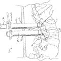
図1を参照すると、本発明に係るシステム10の一実施形態が示される。システム10は、通常、第一アンカー12、第二アンカー14、および連結部材または固定部材16を含み、その部材は患者の脊椎の少なくとも一部を固定するために第一および第二アンカー12、14の間で連結および/または伸びるように構成される。第一アンカー12は、第一経皮的開口部18を介して第一患者の体内に配置可能であり、第二アンカー14は、第二経皮的開口部20を介して第二患者の体内に配置可能である。一実施形態において、第一および第二アンカー12、14は、第一および第二椎骨21、23に係合するように構成されている。固定部材16は、第一および第二アンカー12、14に係合および連結するように第一経皮的開口部18を介して患者の体内に配置可能である。スリーブ22、24は、アンカー12、14から伸び、アンカー12、14および固定部材16の挿入ならびに固定部材16のアンカー12、14への固定を容易にする。固定部材16は、アンカー12、14の収容部またはチャネル26に経皮的または非経皮的に埋入されてもよい。連結部材または固定部材16は、通常、細長いロッドまたはシャフトを含む。固定部材16は、弓状または曲線状であってもよい。しかしながら、代替実施形態において、固定部材16は、ロッド、インプラント、またはファスナーとして既知であるいかなる形態も含むことが可能で、一直線または複合曲率を含むその長さに沿ったいかなる曲線も有することができる。図1に示されるように、固定部材挿入装置30は、固定部材16がアンカー12、14に挿入し易いように、スリーブ22に挿入されてもよい。
Referring to FIG. 1, one embodiment of a
一実施形態において、固定部材挿入装置30は、固定部材16と解放可能かつ回転可能に接続され、固定部材挿入装置30はスリーブ22、24内に収容されるように構成されて寸法がとられ、その結果、挿入装置30および固定部材16がスリーブ内で縦方向に可動となり、固定部材16がアンカー12、14に隣接して配置される。以下にさらに詳細に説明するように、固定部材16は、スリーブ軸に実質的に平行である第一方向でスリーブを介して送達可能であり、第一方向に角度を成す第二方向に回転可能である。さらに、固定部材16は、スリーブ軸に沿った動きに依存しない挿入装置30によって回転可能に作動可能である。つまり、固定部材16は、挿入装置30によって、スリーブ22、24の長さに沿ってどこにおいて回転してもよい。そのような機能は、例えば、固定部材16が埋入中に体内組織を介して移動する経路またはルートを調整するために、特に有利でありうる。さらに、固定部材の回転に関する独立した側面により、回転は、スリーブ22、24に対して挿入装置を動かさずに作動または独立して制御されてもよい。この点において、固定部材16の回転は、スリーブおよび/またはアンカーに下向きの力を加えずに回転してもよい。
In one embodiment, the securing
第一および第二アンカー12、14の各々は、通常、頭部34および骨と係合するねじ山のあるシャフトまたはシャンク36を有する骨ねじ32などの骨ファスナーを含む。図2で示されるように、ねじ32は、中心軸39に沿って伸びる中心通路または管38によりカニューレ状であるが、非カニューレ状のねじも使用してよい。頭部34は、駆動ツールを収容するように構成されるツール係合表面または開口部40を含み、トルクを提供してねじを骨にねじ込む。一実施形態において、ねじ32は、ねじ32のヘッド34に枢着される結合要素42を有する多軸ねじアセンブリである。この点において、ねじ32は、結合要素42内で回転可能であり、複数の角度をとることができる。本発明で使用してもよい多軸ねじの一例は、同時係属の米国特許出願第10/826,285号に説明されており、その内容は、参照することにより組み込まれる。
Each of the first and
図2の実施形態を参照すると、結合要素42は、固定部材16を収容するように構成されて適合される。通常、結合要素42は、固定部材16が、例えばロックキャップにより適切な位置にロックまたは固定され得るチャネル26を構成するU字形の本体44を含む。代替実施形態において、固定部材16をアンカーに堅く結合するための代替手段を、当業者が使用してもよく、結合要素およびロック装置または方法の代替の形態を含む。一実施形態において、結合要素42は、スリーブ22、24と接続する機能を含む。
With reference to the embodiment of FIG. 2, the
例示される実施形態において、スリーブ22、24は、アンカー12、14の各々から伸びてもよく、患者の体を介した入口または通路を提供してアンカー12、14にアクセスしてもよい。図3−6を参照すると、本発明に係るスリーブ50の一実施形態が、近位端56から遠位端58に軸60に沿って伸びる内側スリーブ部材52および外側スリーブ部材54を含むようにして示される。内側スリーブ部材52および外側スリーブ部材54は、スリーブ50を介して軸方向に伸びる中心チャネル62を有し、スリーブ部材52、54は、相互に対して軸方向に摺動可能である。外側スリーブ部材54は、通常、遠位方向に先端部64から軸方向に伸びる、通常は円筒形の先端部64および一対の通常は剛体のアーム66、68を有する延長チューブを含む。内側スリーブ部材52は、通常、遠位方向に先端部70から軸方向に伸びる、通常は円筒型の先端部70および一対の半円筒形の柔軟性のあるアーム72、74を有する延長チューブを含む。スロットまたは開口部76は、スリーブ50の側面に沿って伸び、スリーブ50の中心チャネル62にアクセスできるようにする。開口部76は、スリーブ部材の先端部から遠位端まで、内側および外側スリーブ部材のアーム間で軸方向に伸びる。一実施形態によれば、スロット78は内側スリーブ部材52の先端部64の近位端に隣接して提供されてもよく、その結果、外側スリーブ部材54の先端部70から放射状に内側に伸びるピン80が係合され、スリーブ部材52、54が一緒に正しい位置に設置され、内側および外側スリーブ部材間の開口部76が位置合わせされる。スリーブ50は、手術器具に適したいかなる材料から形成されてもよい。一つの好適な実施形態において、スリーブ50は、金属材料から形成されてもよい。
In the illustrated embodiment, the
操作の際、内側スリーブ部材52のアーム72、74は、特定の適用次第で、内側放射状に圧縮されてもよく、あるいは外側放射状に伸長されてもよい。また、内側スリーブ部材52は、その遠位端に保持部82を含み、スリーブ50の遠位端にアンカーを取り付けるようにしてもよい。図4でよくわかるように、アーム72、74は、遠位端から横方向内側に伸びるフィンガー部材84を含み、付加的な保持能力を提供してもよい。
In operation, the
図3−5において、スリーブ50は、骨ねじ32の結合要素42が、スリーブ50の内側スリーブ部材52の遠位端58で保持部82内に収容されるように示される。一変形例において、内側スリーブ部材52が外側スリーブ部材から軸方向外側に伸長される場合(図3に示されるような位置)に、骨ねじ32は、底部または遠位端58から内側スリーブ部材52に挿入されてもよい。この点において、保持部82は、ねじ32の結合要素42をスナップ式にまたは弾性的に収容してもよい。保持部82の内壁85は、結合要素42の外周に一致するように構成され、内側スリーブ部材52のアーム72、74が、放射状内側に圧縮される場合に、ねじ32の結合要素42が、スリーブ50に対して回転するようにして軸方向に固定される、あるいはスリーブ50内に放射状に収容される。図6に示されるように、一実施形態において、保持部82の内壁85は、底部隆線壁86および上部隆線壁88を含む。底部隆線壁86は、ねじ32の結合要素42の裏面に係合するように構成されて適合され、上部隆線壁88は、スリーブ50に対してねじ32を軸方向に固定するために、結合要素42の上部に係合するように形成かつ適合される。外側スリーブ部材54が内側スリーブ部材52の上に摺動して降りてくる場合、内側スリーブ部材52は、結合要素42を圧縮または放射状に収容し、保持部82の内壁85にそれを堅く保持する。さらにフィンガー部材84は、結合要素42の側面に沿って付加的な保持能力を提供する。その際、アンカー12、14は、スリーブ50に装着され、スリーブ50に対し固定位置に保持されてもよい。またスリーブ50の軸60は、骨ねじ32の軸39に位置合わせされ、その結果ガイドワイヤーまたはツールがねじ32に挿入される場合に、ねじ32およびスリーブ50は、この位置合わせされた位置に維持される。さらに、結合要素がスリーブ50に取り付けられる場合に、チャネル26または固定部材の収容部分は、障害物がないようにして、固定部材またはロッドが、例えば、チャネル26に挿入中にスリーブの内部から内側に伸びる棚、ガイド、斜面、その他のいかなる突起物によっても妨げられないようにする。さらに、チャネル26に固定部材を埋入すると、固定部材をチャネル26に挿入する前にそのような障害を取り除く必要がないので、簡素化される。
In FIGS. 3-5, the
図18を参照すると、図1のシステム10と共に使用してもよい位置合わせツール200の一実施形態が示される。位置合わせツール200は、通常、スリーブ取り付け部材204との間で伸びる連結要素202を含む。スリーブ取り付け部材204は、スリーブ22、24の近位端205に取り付けられるように構成されて寸法がとられる。一変形例において、連結要素202は、円筒形の断面を有してもよい。その他の実施形態において、連結要素202は、多角形または多側面の断面を有してもよい。図18の実施形態において、連結要素202は、スリーブ22、24の側面から伸びるように示されているが、代替実施形態において、連結要素202は、スリーブ22、24の片側または両側に連結するように配置または位置してもよい。連結要素202は、スリーブ取り付け部材204に連結されるように構成され、共通の平面でスリーブ22、24の拘束または位置合わせをする。例えば、図18に示されるように、位置合わせツール200がシステム10に取り付けられる際に、スリーブ22の縦軸206は、スリーブ24の軸208と同一平面上にある。伸長することにより、アンカー12、14のチャネルは位置合わせされ、その結果固定部材16は挿入される際、第一アンカー12から第二アンカー14に位置合わせされ伸長する。図18に示されるような一実施形態において、連結要素202は、縦方向のロッド210を含む。図19を参照すると、連結要素202の別の実施形態が示され、要素202は、スロット213を有する棒または板212を含む。代替実施形態において、連結要素202は、当業者に既知である代替え形状を有してもよく、連結されるスリーブ22、24の軸206、208は、位置合わせツール200が取り付けられる際に、同じ平面上に存在するようになる。
Referring to FIG. 18, one embodiment of an
図20を参照すると、一実施形態において、スリーブ取り付け部材204は、C字形のクリップ214を含んでもよい。クリップ214は、通常、スリーブ22、24の近位端205に係合および取り付けるように構成されて寸法がとられた開口端216を画定するアーム215を含む。その際、クリップ214は、その内面に平行な平面218を含み、結果としてスリーブ22、24の開口部220に係合、一致、および/または位置合わせをし、クリップ214に対して固定位置にスリーブ22、24を保持してもよい。一変形例において、クリップ214は、内面から放射状内側に伸びる突起部222を含み、クリップ214がスナップ式にスリーブ22、24に係合するようにしてもよい。ねじ山のある取り付け穴224は、クリップ214のアーム215から伸びて、そこに連結要素202を装着する。例えば、図19に示されるスロット付きの棒に関する実施形態において、位置決めねじ226を、スロットのある板212をクリップ214に取り付けるために使用してもよい。また、スリーブ22、24が位置合わせツール200で位置合わせされると、スリーブ22、24が全体として相互に移動する柔軟性が残る。一旦取り付けられると、スロットのある板212は、スロット213に沿って調整されて、スリーブ22、24の近位端205をさらに近づけたりさらに遠ざけたり必要に応じて移動してもよい。同様に、図18に示されるロッド状の連結要素においては、スリーブ22、24の近位端205を、ロッド210に沿って移動してもよい。さらに、一旦、位置合わせツール200をシステム10に取り付けたら、スリーブ22、24を、遠位端207の周囲で角度を保ちながら共に移動してもよいが、軸206、208の同一平面上の関係およびアンカー12、14のチャネル26の位置合わせは保持する。
Referring to FIG. 20, in one embodiment, the
図7−12を参照すると、固定部材16および挿入装置30の一実施形態が示される。図8および9において示されるように、固定部材16は、通常、近位端102から遠位端104へ軸106に沿って伸びる細長いロッド100を含む。一実施形態において、ロッド100は、その長さに沿って曲線状または弓状である。しかしながら、代替実施形態において、ロッド100は、いかなる代替え形状であってもよい。本実施形態の一態様によれば、ロッド100は、通常、テーパー状または円錐状の先または先端108をその遠位端104に含み、ロッド100が患者の体に挿入および埋入されるのを容易にする。代替実施形態において、先端108は、多様な形状およびサイズを有してもよい。
With reference to FIGS. 7-12, one embodiment of the securing
接続コネクタ110は、ロッド100の近位端102に提供され、ロッド100の近位端102から近位に伸びる一対の通常は平面のアーム部材112、114を含む。穴116、118は、各アーム部材112、114を介してそれぞれ伸び、接続軸120に沿って同軸上に配置される。穴116、118は、挿入装置30の駆動リンクアーム132に接続して係合するように構成されて寸法がとられる。一実施形態において、ロッド100は、アーム132に取り外し可能なように接続し、ロッド100が、挿入装置30の操作者によってアーム132から要望に応じて取り外しされるようにする。別の実施形態において、球状の戻り止め134は、穴116、118に係合するようにアーム132から外側に突き出る。その際、スロット122に隣接して穴116、118を提供してもよく、その結果穴116、118から球状の戻り止めの挿入および除去をし易くする。
The
図8を再び参照すると、一実施形態において、ロッド100は、ロッド100の近位端102から間隔を取った一対の正反対の位置にあるくぼみ124を含んでもよい。くぼみ124は、ロッド100の中心軸平面に、通常は垂直に伸びるピボット軸126の同軸上に位置合わせされ、ピボット軸126は、通常、ロッド100が枢動し得る軸を構成する。くぼみ124は、挿入装置30のピボットアーム136、137に解放可能かつ回転可能に係合するように構成されて寸法がとられ、ロッド100がピボットアーム136、137に対して枢動するようにしてもよい。好適な実施形態において、くぼみ124は、ピボットアーム136、137から伸びる半球形の突起部138に連動して係合する半球形の凹形状を有する。図9A−9Cに示されるような代替実施形態において、くぼみ124は、軸126に沿って見る場合に、図9Aに示すような一対の横方向に空間をとった半球形のくぼみ125、図9Bに示すような一対の横方向に空間をとった長方形のくぼみ127、または図9Cに示すような一対の横方向に空間をとった三角形のくぼみ129などの、代替えの形状を有してもよい。ロッド100をピボットアーム136、137に取り付けるために、ピボットアームは、若干弾性的に伸長して、突起部138がくぼみ124に係合または留められるようにしてもよい。操作の際、突起部138がくぼみ124に連動して係合すると、ロッド100は、ピボット軸126の周りで回転または枢動する。
Referring again to FIG. 8, in one embodiment, the
図7および10−12を参照すると、固定部材挿入装置30は、通常、外管140および外管140内に同心円状に配置される内側シャフト142を含む。内側シャフト142は、外管140に対して縦軸144に沿って可動である。ノブ143は、内側シャフト142の雄ねじと結合するように内側にねじ山が入り、ノブ143の回転によって、外管140に対して軸144に沿った内側シャフト142の直線状の平行移動をもたらす。端部材146は、内側シャフト142の遠位端に回転可能に接続し、駆動リンクアーム136の近位端148に軸150の周りで回転可能に接続する。駆動リンクアーム136の遠位端は、ロッド100の近位端102に回転可能に接続される。一対のピボットアーム136、137は、外管140から遠位方向に伸び、ピボット軸126でロッド100に解放可能に接続される。操作の際、シャフト142が、外管140に対して軸144に沿って下方つまり遠位方向に移動する時、駆動リンクアーム136は、ロッド100の近位端102を下方向つまり遠位方向に押し込み、または駆動し、ロッド100がピボット軸126の周りで回転または枢動するようにする。したがって、ロッド100は、通常は真っすぐの方向または位置、つまり軸144が軸106に位置合わせされるか、それに平行である位置(図10)からより水平な方向または位置、つまり軸144が軸106に対して垂直または角度を成すような位置(図11)に移動可能である。上に説明されたように、一実施形態において、固定部材16は、スリーブ軸に沿った動きに依存しない挿入装置30によって回転可能に作動可能であり、つまり、固定部材16は、挿入装置30によって、スリーブ22、24の長さに沿ってどの位置で回転してもよい。
With reference to FIGS. 7 and 10-12, the fixation
次に、図21−28を参照すると、固定部材228および挿入装置230の別の実施形態が示される。図22および図23に示されるように、固定部材228は、通常、軸238に沿って近位端234から遠位端236に伸びる細長いロッド232を含む。ロッド232は、多くの点においてロッド100と類似しているが、近位端234は、ロッド100の近位端102と異なる。ロッド232の近位端234は、通常、縦軸238に対して角度を成す凹面または曲線的な傾斜先端面240を含み、それは、挿入装置230の作動または押し込み部材242と係合するように構成されて寸法がとられる。上に説明されたロッド100に類似するロッド232は、くぼみ124のように機能する正反対に位置するくぼみ244を含み、ロッド232が挿入装置230に連結される際に、くぼみの間で伸びるピボット軸246の周りでロッド232が回転するようにしてもよい。
Referring now to FIGS. 21-28, another embodiment of the securing
再び図21を参照すると、固定部材挿入装置230は、挿入装置30と類似しているが、ロッド232は、ロッド100の近位端102に関する上述の説明のように、その近位端234で駆動リンクアームに確実に接続されない。挿入装置230は、通常、フォーク状のアセンブリ250、押し込みアセンブリ252、および保持チューブアセンブリ254を含む。図24でよくわかるように、フォーク状のアセンブリ250は、通常、近位端258で細長いシャフト256を含み、遠位端262で一対の叉またはフォーク状の先260を含む。図25−27でよくわかるように、押し込みアセンブリ252は、通常、中空の回転シャフト264にスライダ266により接続して連結される押し込み部材242を含む。スライダ266は、回転シャフト264にその遠位端で自由に回転可能に連結され、その結果シャフト264の回転により、軸245に沿った遠位方向におけるスライダ266の平行移動が起こる。装置230は、装置30に類似しているが、装置30の駆動リンクアーム136は、ロッド232の近位端234に押し込みながらおよび/または摺動しながら係合するように構成され寸法がとられた遠位端268を含む、押し込み部材242と取り替えられる。一対のフォーク状の先端260は、フォーク状のアセンブリ250から遠位に伸びて、ピボット軸246で係合する球状の戻り止め270によってロッド232に解放可能に接続する。その際、先端260は、弾性的かつ外側に伸長可能であり、ロッド232は、フォーク状のアセンブリ250の遠位端に隣接して配置される戻り止め270の間に挿入されるようになる。
Referring again to FIG. 21, the fixation
フォーク状のアセンブリ250は、中空の回転シャフト264内で連動して収容されるように寸法がとられ、その結果、先端260が、押し込み部材242の片側で伸びるようにする。フォーク状のアセンブリ250のねじ山部分257は、ノブ265の雌ねじ山と接合するように構成される。保持チューブアセンブリ254は、通常、スリーブ22、24のピン276に係合するように構成される縦方向のスロット274を有する円筒状のチューブ272を含み、その結果スリーブ22、24に関して適切な角度位置合わせが確実に行われるようになる。ハンドル278は、チューブ272をスリーブ22、24に挿入し易くするため提供されてもよく、チューブ272がスリーブ22、24まで十分な長さを確実に伸ばすため縦方向または軸方向のストップを提供するために与えられてもよく、その結果、スリーブ22、24の遠位端に取り付けられるアンカー12、14にロッド232が十分近位に配置されるようになる。
The fork-
操作の際、ノブ265が回転すると、回転シャフト264はフォーク状のアセンブリ250に対して回転し、スライダ266は、軸245に沿って下方、つまり遠位方向に移動し、押し込み部材242は、ロッド232の近位端234を下方、つまり遠位方向に押し込むか駆動して、ロッド232がピボット軸246の周りで回転または枢動するようにする。したがって、ロッド232は、通常は真っすぐの方向または位置、つまり軸245が軸247に位置合わせされる位置から、より水平な方向または位置、つまり軸245が軸247に対して垂直または角度を成すような位置に移動可能である。上に説明されたように、一実施形態において、固定部材16は、スリーブ軸に沿った動きに依存しない挿入装置230によって回転可能で作動可能である。つまり、固定部材16は、挿入装置230によって、スリーブ22、24の長さに沿ったどこにおいても回転してもよい。
In operation, as the knob 265 rotates, the
一般的に、挿入装置30および230は、各装置が、通常、第一部材および第二部材を含む点で類似し、第一部材は、装置の縦軸に沿って第二部材に対して直線的に平行移動可能であり、固定部材は、第一部材に接続して係合され、第二部材に回転可能に係合される。第一部材が、縦軸に沿って第二部材に対して平行移動される場合、固定部材は第二部材の周りを回転する。
In general,
次に図13−15を参照すると、本発明に係る伸延ツール150の一実施形態が示される。伸延(distractor)ツール150は、上に説明された挿入装置30のように動作するが、通常、その遠位端154に接続して取り付けられる真っすぐな伸延棒152を有する。伸延棒152の近位端156は、伸延棒152を軸160の周りで回転させる押し込みロッド158の遠位端と回転可能に接続される。操作の際、押し込みロッド158が軸162に沿って下方つまり遠位方向に移動されると、押し込みロッド158は、伸延棒152の近位端156を下方つまり遠位方向に押し込むか駆動して、伸延棒スリーブ50または170152を軸160の周りで回転させる。したがって、伸延棒152は、通常は真っすぐの方向または位置、つまり軸162が軸164に位置合わせされる位置(図14)から、より水平な方向または位置、つまり軸162が軸164に対して垂直であるような位置(図15)に移動可能である。伸延ツール150は、スリーブ50または170内に収容されるように構成されて寸法がとられ、それを第一および第二アンカー12、14との間に配置される組織を伸延または移動させるように使用してもよい。この点において、伸延ツール150は、患者の体内経路をクリアにするために外科医によって使用されて、その後、固定部材16の挿入がより容易に挿入されるようにしてもよい。本発明の一態様によれば、伸延棒152は、角度のある先端を有し、通常、組織分離を容易にするように真っすぐの刃のような形状である。
13-15, one embodiment of a distraction tool 150 according to the present invention is shown. The distractor tool 150 operates like the
次に図29−35を参照すると、本明細書に説明される経皮的システムと共に利用されるように構成されて寸法がとられるロッドレデューサー器具300の一実施形態が示される。ロッドレデューサー器具300は、通常、回転シャフト302、レデューサーシャフト304、およびスリーブ22、24の近位端に係合および取り付けられるように構成されるスリーブ306を含む。回転シャフト302は、シャフト302の遠位端に隣接した貫通孔310を含み、回転シャフト302をレデューサーシャフト304に軸方向に連結するピン312を収容するように構成される。ピン312は、シャフト304の放射状のスロット314に係合するように構成され、シャフト304が自由に回転するようにするが、それでもシャフト302に軸方向に固定されている。回転シャフト302は、取り付けスリーブ306の内側に沿った対応する雌ねじとねじ山と係合または結合するように構成されるシャフトの一部に沿った雄ねじ部分308を含む。図35を参照すると、取り付けスリーブ306は通常、、横方向の開口部316を構成し、遠位端に隣接するアーム315を有する遠位端を含み、その開口部316は、スリーブ22、24の近位端205に係合および取り付けるように構成されて寸法がとられる。その際、アーム315は、その内面に平行な平面318を含んで、そこに取り付けられるスリーブ22、24に対して固定位置に取り付けスリーブ306を保持するために、スリーブ22、24の開口部220に係合、一致、および/または位置合わせするようにしてもよい。
Referring now to FIGS. 29-35, there is shown one embodiment of a
図33でよくわかるように、レデューサーシャフト304は、そこから伸びる中心管320を含むカニューレ状のシャフトである。放射状のくぼみまたはスロット314は、回転シャフト302と軸方向に連結するために、近位端に隣接して提供される。シャフト304の近位端は、シャフト304を回転し易くするために回転ツール係合機能を含み、シャフト304の遠位端は、キャップを保持するように構成される。図34を参照すると、一実施形態において、遠位端は、キャップを係合するように内側に伸びるキャップ係合または保持突起部322を含む。さらに、ファスナーキャップを解放可能に係合するために、シャフト304の遠位端のわずかな動きを可能にするように一対のスリット324を提供してもよい。キースロット326を、スリーブ22、24と、その遠位端に取り付けられる伸長アンカー12、14によって挿入して位置合わせしやすいように提供してもよい。遠位端で保持されるキャップは、ロッドに係合するようにチャネルまたは溝を有して、ロッドをファスナーに向けて下に押し込むようにする。図31および32を参照すると、操作の際、シャフト302が、取り付けスリーブ306に対してねじ山で回転すると、レデューサーシャフト304は、軸方向に平行移動するが回転はせず、軸方向に使用され得る力を提供し、例えば、ファスナーから間隔をとった第一位置(図31)から、スリーブ22、24の遠位端でファスナーに近位の第二位置(図32)に移動するように脊椎ロッドに力を加える。適切な位置に配置されると、レデューサーシャフト304は、キャップを各ファスナーにクリックおよび/または埋入するために回転することができる。一実施形態において、六角ドライバは、レデューサーシャフト304の近位端に係合するように、カニューレ状の回転シャフト302を介して挿入されてもよく、それにより、レデューサーシャフト304が回転し、ファスナーの近位端にキャップを埋入するようにファスナーに対してキャップが回転する。キャップが埋入されると、別の駆動ツールが、シャフト304の回転シャフト302および管320を介して挿入されて、位置決めねじに回転可能に係合するようにしてもよく、その位置決めねじは、次に、ロッドを適切な位置に固定するために締め付けることができる。ロッドレデューサー器具300は、次に、固定部材16をアンカー12、14に埋入した状態で、スリーブ22、24から取り除かれることができる。
As can be seen in FIG. 33, the
図16−17を参照すると、本発明に係るスリーブ170の代替実施形態が示される。スリーブ170は、通常、縦軸178に沿って、近位端174から遠位端176に伸びる単一のスリーブ本体172を含む。中心チャネル180は、スリーブ本体172を介して軸方向に伸び、一対の縦方向のスロットまたは開口部182は、スリーブ本体172の正反対に位置する側面に沿いにスリーブ側壁184を介して伸びて、中心チャネル180へのアクセスを提供する。中心チャネル180は、端面図で見る場合に、いかなる所望の断面形状を有してもよい。一実施形態において、中心チャネル180は、ねじキャップ(図示せず)がそこに挿入されるようなサイズと寸法である。好適な実施形態において、チャネル180は、そこにねじを収容するようなサイズと寸法であり、ねじが、スリーブ170の先端つまり近位端174から挿入されてもよいようにする。スリーブ170は、側壁184と一体化した一つ以上の弾力性のあるツメ186も含んでもよい。ツメ186は、放射状に内側に突出する傾斜部188およびリップ部190を含む。図2に示されるねじ32のようなねじがスリーブ170の近位端174から挿入されて、遠位端176に向かって軸方向に摺動されると、ねじ32の結合要素42は、傾斜部188に係合し、ツメ186を押し出し、または放射状に伸長して、ねじ32がリップ部190を越えて遠位に移動するようにする。ねじ32がリップ部190を越えて遠位に配置されると、ツメ186は、放射状内側に弾性的に跳ね返り、リップ部190が結合要素42を上方つまり近位方向に移動しないようにする。
With reference to FIGS. 16-17, an alternative embodiment of a
スリーブ170は、上に説明した図3−6の実施形態に類似した保持部194をその遠位端に有するが、本実施形態においては、ねじ32は、上部からスリーブ170の近位端174に搭載または挿入されると想定される。本発明の別の機能において、スリーブ170は、分解可能または分離可能な連結をその遠位端に含む。この点において、スリーブ170は、スリーブ170をその遠位端176で制御して分解し易いように分解線または切り込み196を含んでもよい。スリーブ170は、手術器具に適したいかなる材料からも形成されてもよい。一つの好適な実施形態において、スリーブ170は、プラスチック材料から形成されてもよい。
The
上に説明されたシステムおよび装置を使用する外科技術または方法について以下に説明する。本発明の一実施形態によれば、アンカー12、14は、経皮的に椎骨に埋め込まれてもよい。一好適な形態において、アンカー12、14のうちの各々は、スリーブ50または170に取り付けられ、装着され、または保持され、そのスリーブ50または170ならびに取り付けられたアンカーは、切開部、チューブまたはカニューレ、あるいは直接患者の皮膚および組織を介して挿入されて、図1に示されるような椎弓根などの骨にアンカー12、14を埋め込むようにする。代替実施形態において、アンカー12、14は、そこに取り付けられるスリーブ50または170無しで骨に埋め込まれることが可能で、スリーブ50または170は、埋め込まれた後にアンカーに装着されてもよい。
A surgical technique or method using the system and apparatus described above is described below. According to one embodiment of the invention, the
本発明の方法は、椎骨におけるアンカーの最適な配置および方向を決定および位置付けるため、ならびに/もしくは、アンカーを入れるための経皮的皮膚穿刺の位置を特定するために、当業者に既知であるいかなる画像システムも用いることができる。アンカー12、14の椎骨における位置決めおよび配置のための技術者に既知であるその他の方法も使用されてもよく、その方法にはCTスキャンまたはX線、あらゆる既知の表示器具または装置、内視鏡的および顕微鏡的モニタリングを含むがそれだけに限定されない。
The method of the present invention may be any known to those skilled in the art to determine and position the optimal placement and orientation of the anchor in the vertebra and / or to locate the percutaneous skin puncture for placement of the anchor. An imaging system can also be used. Other methods known to those skilled in the art for positioning and placement of
一実施形態において、椎弓根の進入点の位置決めの後、椎弓根の経皮的な器具の使用は、アンカーが埋め込まれる椎体の椎間関節と横突起との交差点に、カニューレ状の針を患者の皮膚を介して挿入することから始めてもよい。キルシュナー鋼線またはガイドワイヤーを、針のカニューレを介して椎弓根に挿入してもよい。その後引き続いて、伸長カニューレがガイドワイヤーを介して挿入されて、作業中のカニューレがアンカー12または14を収容するのに十分大きくなるまで筋膜および筋肉を伸長してもよい。最大のカニューレ以外のもの全てが作業中のカニューレから取り除かれて、皮膚を介した椎弓根または挿入部への通路を露出してもよい。一実施形態において、椎弓根における穴は、ガイドワイヤーを介して作業中のカニューレによってカニューレ状のドリルおよび栓を配置することにより形成され、ねじ挿入のために椎弓根の下準備をする。その他の実施形態において、椎弓根は、当技術分野において既知であるその他の器具で下準備されてもよく、その器具には、千枚通し、トロカール、および針が含まれるがそれだけに限定されない。
In one embodiment, after positioning of the pedicle entry point, the use of a pedicle percutaneous device cannulated at the intersection of the vertebral facet joint and transverse process in which the anchor is implanted. You may begin by inserting a needle through the patient's skin. A Kirschner steel wire or guide wire may be inserted into the pedicle via the needle cannula. Subsequently, an extension cannula may be inserted through the guide wire to extend the fascia and muscle until the working cannula is large enough to accommodate the
椎弓根が下準備されたら、スリーブ50または170に取り付けられるねじ32などのカニューレ状のアンカーを、ガイドワイヤーを介して作業中のカニューレによって、準備される穴まで進めてもよい。カニューレ上のねじ回しなどの駆動ツールは、ねじ32を回転させるために使用されてもよく、骨にねじ32をねじ山で係合する。スリーブ50または170は、ねじ32が骨にねじ込まれると、骨までねじ32をたどり、ねじ回しおよびガイドワイヤーは取り除かれる。作業中のカニューレもその後取り除かれるが、スリーブ50または170およびねじ32は骨に固定されて残される。
Once the pedicle is prepared, a cannulated anchor such as screw 32 attached to
アンカー12、14が、骨およびそこから伸びるスリーブ50または170に固定された状態で、アンカー12、14の結合要素42および各スリーブのスロットまたは開口部76は方向付けまたは位置合わせされてもよい。一実施形態において、位置合わせツール(図示せず)は、スリーブの近位端に取り付けられて、スリーブ22、24の対応するスロット76および各アンカー12、14の結合要素42のチャネル26が正しく位置合わせされるようにしてもよい。
With the
固定部材16は、挿入装置30に取り付けられ、アンカー12および14それぞれのチャネル26への挿入準備が整えられる。初めは、固定部材16が、通常、垂直の位置(図10に示されるように)の状態で、挿入装置30はスリーブ22に挿入される。挿入装置30がスリーブ22内で遠位方向に進められ、シャフト142が遠位方向に移動されると、ロッド100は、より水平な位置(図11に示されるように)までピボット軸126の周りで回転または枢動する。この点に関して、挿入装置30は、アンカー12、14に向かって遠位方向に固定部材16を移動させる。ロッド100の近位端は、スリーブ22の開口部76を介して外側に揺れ、固定部材16の遠位端108は、アンカー12、14の位置合わせされたチャネル26に向かって進められる。好適な一実施形態において、挿入装置30が遠位にスリーブ22に進められ、シャフト142が挿入装置30の外側本体140に対して遠位に進められると、固定部材16の先端108は、通常は楕円形の経路をたどって、第一開口部18を介して患者に入り、第二アンカーのチャネル26を介して第二アンカー14に向かって移動する。ロッド100がより水平の位置にある状態で、ロッド100は、次に、ロッド挿入ツール30をスリーブ22の遠位端に向かって遠位に進めることによって、第一アンカー12のチャネル26に挿入されてもよい。
The securing
固定部材16がアンカー12、14のチャネル26内の必要な位置に配置されると、キャップおよび/または位置決めねじが、スリーブ24を介して下方に駆動され、固定部材16と接触し、固定部材16をアンカー14に固定する。駆動ツールは、スリーブ24の中心チャネルを介して配置されて、固定部材がアンカー14の結合要素42にしっかりと着座するまで、キャップおよび/または位置決めねじを固定部材に対して締め付けるようにしてもよい。固定部材16がアンカー14に固定された状態で、挿入装置30は、次に、固定部材16から離され、スリーブ22から取り除かれることが可能で、キャップは、固定部材16をアンカー12に固定するのと同様の方法でスリーブ22を介して挿入されてもよい。スリーブ50に関して、外側スリーブ部材54は、内側スリーブ部材52が伸長状態(図3に示されるように)であるように格納されてもよく、その結果内側スリーブ部材のアーム72、74が外側に伸長されて、埋入された固定部材16の周囲で取り除かれるようになる。別の実施形態において、スリーブ170が使用される場合、遠位端176は、分解線または切り込み196に沿って分解されて、スリーブ170の遠位端176が、埋入された固定部材16の周囲で取り除かれるようにしてもよい。
When the securing
本明細書に開示される本発明は、特定の実施形態およびその適用を参照して説明されているが、それに対する多くの修正および変形が、請求項に記載の本発明の範囲から逸脱しなければ、当業者により加えられることが可能である。 Although the invention disclosed herein has been described with reference to particular embodiments and applications thereof, many modifications and variations thereto should depart from the scope of the invention as set forth in the claims. Can be added by those skilled in the art.
本発明は、添付の図面に示されるその実施形態を参照して、さらに容易に理解されるだろう。図面における同様の数字は、同様の機能および構造を言及することが理解されたい。
Claims (14)
前記第一アンカーに係合するために、前記第一経皮的開口部を介して配置可能である固定部材と、
解放可能かつ回転可能に前記固定部材に接続される固定部材挿入装置であって、前記中心チャネル内に収容されるように構成されて寸法がとられ、前記固定部材を前記第一アンカーに隣接して配置するために、前記挿入装置および固定部材が前記縦軸に沿って縦方向に可動である、固定部材挿入装置と
を含み、
前記固定部材は、前記アクセススリーブの前記縦軸に実質的に平行である第一方向で、前記アクセススリーブにおける前記中心チャネルを介して送達可能であり、
前記縦軸に沿った動きとは独立して、前記第一アンカーに対して前記固定部材を配置するために、前記第一方向に対して角度を成す第二方向で延長するように、前記固定部材が、前記固定部材挿入装置によって回転可能に作動可能であり、
前記固定部材挿入装置は、近位端から遠位端まで第二長手軸に沿って伸張し、
前記固定部材挿入装置は、第一部材及び第二部材を備え、前記第一部材は、前記第二部材に対して、前記第二長手軸に沿って直線的に移動可能であり、
前記固定部材は、前記固定部材に沿った第一軸位置において、第一部材に接続して係合され、前記第一軸位置から軸方向にオフセットされた前記固定部材に沿った第二軸位置において、第二部材に回転可能に係合されており、
前記第一部材が、前記第二長手軸に沿って前記第二部材に対して移動されるとき、前記固定部材は前記第二部材について回転する、
経皮的脊椎固定システム。A first anchor deliverable to a patient's vertebral body through a first percutaneous opening with the access sleeve coupled thereto, the access sleeve extending therefrom and having a longitudinal axis A first anchor, including a central channel forming;
A securing member positionable through the first percutaneous opening for engaging the first anchor;
A securing member insertion device that is releasably and rotatably connected to the securing member, wherein the securing member insertion device is configured and dimensioned to be received within the central channel, and the securing member is adjacent to the first anchor. A fixing member insertion device, wherein the insertion device and the fixing member are movable in a longitudinal direction along the longitudinal axis,
The securing member is deliverable via the central channel in the access sleeve in a first direction substantially parallel to the longitudinal axis of the access sleeve;
Independently of movement along the longitudinal axis, the securing member is extended so as to extend in a second direction that forms an angle with respect to the first direction to position the securing member relative to the first anchor. member, Ri rotatably actuatable der by the fixing member insertion device,
The securing member insertion device extends along a second longitudinal axis from a proximal end to a distal end;
The fixing member insertion device includes a first member and a second member, and the first member is linearly movable along the second longitudinal axis with respect to the second member,
The fixed member is connected to and engaged with the first member at a first axial position along the fixed member, and a second axial position along the fixed member that is offset in the axial direction from the first axial position. And is rotatably engaged with the second member,
When the first member is moved relative to the second member along the second longitudinal axis, the fixed member rotates about the second member;
Percutaneous spinal fixation system.
Applications Claiming Priority (5)
| Application Number | Priority Date | Filing Date | Title |
|---|---|---|---|
| US67510205P | 2005-04-27 | 2005-04-27 | |
| US60/675,102 | 2005-04-27 | ||
| US11/244,036 US7758617B2 (en) | 2005-04-27 | 2005-10-06 | Percutaneous vertebral stabilization system |
| US11/244,036 | 2005-10-06 | ||
| PCT/US2006/015910 WO2006116544A2 (en) | 2005-04-27 | 2006-04-27 | Percutaneous vertebral stabilization system |
Publications (2)
| Publication Number | Publication Date |
|---|---|
| JP2008539029A JP2008539029A (en) | 2008-11-13 |
| JP5009899B2 true JP5009899B2 (en) | 2012-08-22 |
Family
ID=37215473
Family Applications (1)
| Application Number | Title | Priority Date | Filing Date |
|---|---|---|---|
| JP2008509098A Active JP5009899B2 (en) | 2005-04-27 | 2006-04-27 | Percutaneous spinal fixation system |
Country Status (4)
| Country | Link |
|---|---|
| US (2) | US7758617B2 (en) |
| EP (1) | EP1874236B1 (en) |
| JP (1) | JP5009899B2 (en) |
| WO (1) | WO2006116544A2 (en) |
Families Citing this family (266)
| Publication number | Priority date | Publication date | Assignee | Title |
|---|---|---|---|---|
| US6530929B1 (en) | 1999-10-20 | 2003-03-11 | Sdgi Holdings, Inc. | Instruments for stabilization of bony structures |
| US7833250B2 (en) | 2004-11-10 | 2010-11-16 | Jackson Roger P | Polyaxial bone screw with helically wound capture connection |
| US7862587B2 (en) | 2004-02-27 | 2011-01-04 | Jackson Roger P | Dynamic stabilization assemblies, tool set and method |
| US8353932B2 (en) | 2005-09-30 | 2013-01-15 | Jackson Roger P | Polyaxial bone anchor assembly with one-piece closure, pressure insert and plastic elongate member |
| US8292926B2 (en) | 2005-09-30 | 2012-10-23 | Jackson Roger P | Dynamic stabilization connecting member with elastic core and outer sleeve |
| US10258382B2 (en) | 2007-01-18 | 2019-04-16 | Roger P. Jackson | Rod-cord dynamic connection assemblies with slidable bone anchor attachment members along the cord |
| US10729469B2 (en) | 2006-01-09 | 2020-08-04 | Roger P. Jackson | Flexible spinal stabilization assembly with spacer having off-axis core member |
| US8876868B2 (en) | 2002-09-06 | 2014-11-04 | Roger P. Jackson | Helical guide and advancement flange with radially loaded lip |
| US9539012B2 (en) | 2002-10-30 | 2017-01-10 | Zimmer Spine, Inc. | Spinal stabilization systems with quick-connect sleeve assemblies for use in surgical procedures |
| EP1558157B1 (en) * | 2002-10-30 | 2012-11-21 | Zimmer Spine, Inc. | Spinal stabilization system insertion |
| US7887539B2 (en) | 2003-01-24 | 2011-02-15 | Depuy Spine, Inc. | Spinal rod approximators |
| US7621918B2 (en) | 2004-11-23 | 2009-11-24 | Jackson Roger P | Spinal fixation tool set and method |
| US7377923B2 (en) | 2003-05-22 | 2008-05-27 | Alphatec Spine, Inc. | Variable angle spinal screw assembly |
| US8936623B2 (en) | 2003-06-18 | 2015-01-20 | Roger P. Jackson | Polyaxial bone screw assembly |
| US7776067B2 (en) | 2005-05-27 | 2010-08-17 | Jackson Roger P | Polyaxial bone screw with shank articulation pressure insert and method |
| US8366753B2 (en) | 2003-06-18 | 2013-02-05 | Jackson Roger P | Polyaxial bone screw assembly with fixed retaining structure |
| US7967850B2 (en) | 2003-06-18 | 2011-06-28 | Jackson Roger P | Polyaxial bone anchor with helical capture connection, insert and dual locking assembly |
| US7766915B2 (en) | 2004-02-27 | 2010-08-03 | Jackson Roger P | Dynamic fixation assemblies with inner core and outer coil-like member |
| US7955355B2 (en) | 2003-09-24 | 2011-06-07 | Stryker Spine | Methods and devices for improving percutaneous access in minimally invasive surgeries |
| US8002798B2 (en) | 2003-09-24 | 2011-08-23 | Stryker Spine | System and method for spinal implant placement |
| US7527638B2 (en) | 2003-12-16 | 2009-05-05 | Depuy Spine, Inc. | Methods and devices for minimally invasive spinal fixation element placement |
| US11419642B2 (en) | 2003-12-16 | 2022-08-23 | Medos International Sarl | Percutaneous access devices and bone anchor assemblies |
| US7179261B2 (en) | 2003-12-16 | 2007-02-20 | Depuy Spine, Inc. | Percutaneous access devices and bone anchor assemblies |
| US8152810B2 (en) | 2004-11-23 | 2012-04-10 | Jackson Roger P | Spinal fixation tool set and method |
| US9050148B2 (en) | 2004-02-27 | 2015-06-09 | Roger P. Jackson | Spinal fixation tool attachment structure |
| US7160300B2 (en) | 2004-02-27 | 2007-01-09 | Jackson Roger P | Orthopedic implant rod reduction tool set and method |
| CA2701522C (en) | 2004-02-27 | 2012-05-15 | Roger P. Jackson | Orthopedic implant rod reduction tool set and method |
| US11241261B2 (en) | 2005-09-30 | 2022-02-08 | Roger P Jackson | Apparatus and method for soft spinal stabilization using a tensionable cord and releasable end structure |
| US7641690B2 (en) * | 2004-08-23 | 2010-01-05 | Abdou M Samy | Bone fixation and fusion device |
| US7651502B2 (en) | 2004-09-24 | 2010-01-26 | Jackson Roger P | Spinal fixation tool set and method for rod reduction and fastener insertion |
| US7951153B2 (en) | 2004-10-05 | 2011-05-31 | Samy Abdou | Devices and methods for inter-vertebral orthopedic device placement |
| US8267969B2 (en) | 2004-10-20 | 2012-09-18 | Exactech, Inc. | Screw systems and methods for use in stabilization of bone structures |
| US8226690B2 (en) | 2005-07-22 | 2012-07-24 | The Board Of Trustees Of The Leland Stanford Junior University | Systems and methods for stabilization of bone structures |
| US20060095136A1 (en) * | 2004-11-03 | 2006-05-04 | Mcluen Design, Inc. | Bone fusion device |
| US8597360B2 (en) | 2004-11-03 | 2013-12-03 | Neuropro Technologies, Inc. | Bone fusion device |
| US8926672B2 (en) | 2004-11-10 | 2015-01-06 | Roger P. Jackson | Splay control closure for open bone anchor |
| US8444681B2 (en) | 2009-06-15 | 2013-05-21 | Roger P. Jackson | Polyaxial bone anchor with pop-on shank, friction fit retainer and winged insert |
| US9168069B2 (en) | 2009-06-15 | 2015-10-27 | Roger P. Jackson | Polyaxial bone anchor with pop-on shank and winged insert with lower skirt for engaging a friction fit retainer |
| US9216041B2 (en) | 2009-06-15 | 2015-12-22 | Roger P. Jackson | Spinal connecting members with tensioned cords and rigid sleeves for engaging compression inserts |
| US9918745B2 (en) | 2009-06-15 | 2018-03-20 | Roger P. Jackson | Polyaxial bone anchor with pop-on shank and winged insert with friction fit compressive collet |
| US9393047B2 (en) | 2009-06-15 | 2016-07-19 | Roger P. Jackson | Polyaxial bone anchor with pop-on shank and friction fit retainer with low profile edge lock |
| US7875065B2 (en) * | 2004-11-23 | 2011-01-25 | Jackson Roger P | Polyaxial bone screw with multi-part shank retainer and pressure insert |
| US8172855B2 (en) | 2004-11-24 | 2012-05-08 | Abdou M S | Devices and methods for inter-vertebral orthopedic device placement |
| US7811288B2 (en) | 2004-12-02 | 2010-10-12 | Zimmer Spine, Inc. | Instruments and methods for adjusting separation distance of vertebral bodies with a minimally invasive spinal stabilization procedure |
| US7901437B2 (en) | 2007-01-26 | 2011-03-08 | Jackson Roger P | Dynamic stabilization member with molded connection |
| EP1858422A4 (en) * | 2005-02-23 | 2011-12-28 | Pioneer Surgical Technology Inc | Minimally invasive surgical system |
| US7951172B2 (en) | 2005-03-04 | 2011-05-31 | Depuy Spine Sarl | Constrained motion bone screw assembly |
| US7951175B2 (en) | 2005-03-04 | 2011-05-31 | Depuy Spine, Inc. | Instruments and methods for manipulating a vertebra |
| ES2318917B1 (en) * | 2005-03-30 | 2010-02-04 | Sdgi Holdings Inc. | SYSTEM FOR THE THREE-DIMENSIONAL CORRECTION OF THE CURVATURE OF THE VERTEBRAL COLUMN IN PROBLEMS OF SCHOLIOSIS BY COPLANAR ALIGNMENT OF THE PEDICULAR SCREWS. |
| US7942903B2 (en) | 2005-04-12 | 2011-05-17 | Moskowitz Ahmnon D | Bi-directional fixating transvertebral body screws and posterior cervical and lumbar interarticulating joint calibrated stapling devices for spinal fusion |
| US7846188B2 (en) | 2005-04-12 | 2010-12-07 | Moskowitz Nathan C | Bi-directional fixating transvertebral body screws, zero-profile horizontal intervertebral miniplates, total intervertebral body fusion devices, and posterior motion-calibrating interarticulating joint stapling device for spinal fusion |
| US11903849B2 (en) | 2005-04-12 | 2024-02-20 | Moskowitz Family Llc | Intervertebral implant and tool assembly |
| US9314273B2 (en) * | 2005-04-27 | 2016-04-19 | Globus Medical, Inc. | Percutaneous vertebral stabilization system |
| US8177817B2 (en) * | 2005-05-18 | 2012-05-15 | Stryker Spine | System and method for orthopedic implant configuration |
| US7749233B2 (en) * | 2005-06-08 | 2010-07-06 | Innovative Spine, Llc | Sleeve assembly for spinal stabilization system and methods of use |
| US8523865B2 (en) | 2005-07-22 | 2013-09-03 | Exactech, Inc. | Tissue splitter |
| US7909830B2 (en) * | 2005-08-25 | 2011-03-22 | Synthes Usa, Llc | Methods of spinal fixation and instrumentation |
| US8105368B2 (en) | 2005-09-30 | 2012-01-31 | Jackson Roger P | Dynamic stabilization connecting member with slitted core and outer sleeve |
| WO2007044705A2 (en) * | 2005-10-07 | 2007-04-19 | Abdou Samy M | Devices and methods for inter-verterbral orthopedic device placement |
| US7704271B2 (en) | 2005-12-19 | 2010-04-27 | Abdou M Samy | Devices and methods for inter-vertebral orthopedic device placement |
| US20130131729A1 (en) * | 2006-01-25 | 2013-05-23 | Marshall Stauber | Surgical fixation system and method |
| US7497869B2 (en) * | 2006-01-27 | 2009-03-03 | Warsaw Orthopedic, Inc. | Methods and devices for a minimally invasive placement of a rod within a patient |
| CA2637684C (en) | 2006-02-06 | 2011-09-13 | Stryker Spine | Rod contouring apparatus and method for percutaneous pedicle screw extension |
| US8123751B2 (en) * | 2006-06-09 | 2012-02-28 | Zimmer Spine, Inc. | Methods and apparatus for access to and/or treatment of the spine |
| JP5210305B2 (en) * | 2006-06-16 | 2013-06-12 | アルファテック スパイン, インコーポレイテッド | Spinal screw assembly system, system for implanting spinal screw assembly |
| US8303630B2 (en) | 2006-07-27 | 2012-11-06 | Samy Abdou | Devices and methods for the minimally invasive treatment of spinal stenosis |
| US8565853B2 (en) | 2006-08-11 | 2013-10-22 | DePuy Synthes Products, LLC | Simulated bone or tissue manipulation |
| US8663292B2 (en) * | 2006-08-22 | 2014-03-04 | DePuy Synthes Products, LLC | Reduction sleeve |
| US9526525B2 (en) | 2006-08-22 | 2016-12-27 | Neuropro Technologies, Inc. | Percutaneous system for dynamic spinal stabilization |
| US8551141B2 (en) | 2006-08-23 | 2013-10-08 | Pioneer Surgical Technology, Inc. | Minimally invasive surgical system |
| US7686809B2 (en) | 2006-09-25 | 2010-03-30 | Stryker Spine | Rod inserter and rod with reduced diameter end |
| US8038699B2 (en) | 2006-09-26 | 2011-10-18 | Ebi, Llc | Percutaneous instrument assembly |
| US8162952B2 (en) | 2006-09-26 | 2012-04-24 | Ebi, Llc | Percutaneous instrument assembly |
| US8096996B2 (en) | 2007-03-20 | 2012-01-17 | Exactech, Inc. | Rod reducer |
| US8052720B2 (en) * | 2006-11-09 | 2011-11-08 | Zimmer Spine, Inc. | Minimally invasive pedicle screw access system and associated method |
| US8211110B1 (en) | 2006-11-10 | 2012-07-03 | Lanx, Inc. | Minimally invasive tool to facilitate implanting a pedicle screw and housing |
| US7967821B2 (en) * | 2006-11-20 | 2011-06-28 | Depuy Spine, Inc. | Break-off screw extension removal tools |
| US8679128B2 (en) * | 2006-12-07 | 2014-03-25 | Zimmer Spine, Inc. | Apparatus and methods for reduction of vertebral bodies in a spine |
| US20080140132A1 (en) * | 2006-12-07 | 2008-06-12 | Mi4Spine, Llc | Pedicle screw and rod system for minimally invasive spinal fusion surgery |
| AU2007332794C1 (en) | 2006-12-08 | 2012-01-12 | Roger P. Jackson | Tool system for dynamic spinal implants |
| US8475498B2 (en) | 2007-01-18 | 2013-07-02 | Roger P. Jackson | Dynamic stabilization connecting member with cord connection |
| US8366745B2 (en) | 2007-05-01 | 2013-02-05 | Jackson Roger P | Dynamic stabilization assembly having pre-compressed spacers with differential displacements |
| US7648521B2 (en) * | 2007-03-15 | 2010-01-19 | Zimmer Spine, Inc. | System and method for minimally invasive spinal surgery |
| US10383660B2 (en) | 2007-05-01 | 2019-08-20 | Roger P. Jackson | Soft stabilization assemblies with pretensioned cords |
| US8016832B2 (en) * | 2007-05-02 | 2011-09-13 | Zimmer Spine, Inc. | Installation systems for spinal stabilization system and related methods |
| EP3272299B1 (en) * | 2007-05-18 | 2020-05-13 | Stryker European Holdings I, LLC | Apparatus for direct vertebral rotation |
| US8460300B2 (en) * | 2007-06-12 | 2013-06-11 | Zimmer Spine, Inc. | Instrumentation and associated techniques for minimally invasive vertebral rod installation |
| US8043343B2 (en) * | 2007-06-28 | 2011-10-25 | Zimmer Spine, Inc. | Stabilization system and method |
| US8361126B2 (en) | 2007-07-03 | 2013-01-29 | Pioneer Surgical Technology, Inc. | Bone plate system |
| US8623019B2 (en) | 2007-07-03 | 2014-01-07 | Pioneer Surgical Technology, Inc. | Bone plate system |
| US8961523B2 (en) | 2007-07-13 | 2015-02-24 | K2M, Inc. | Rod reduction device and method of use |
| US8709054B2 (en) | 2007-08-07 | 2014-04-29 | Transcorp, Inc. | Implantable vertebral frame systems and related methods for spinal repair |
| US12539219B2 (en) | 2007-08-21 | 2026-02-03 | Moskowitz Family Llc | Intervertebral implant and tool assembly |
| US8900237B2 (en) * | 2007-08-31 | 2014-12-02 | DePuy Synthes Products, LLC | Minimally invasive guide system |
| FR2920663B1 (en) * | 2007-09-10 | 2010-08-27 | Kiscomedica | INSTRUMENT FOR AIDING THE INSTALLATION OF A SYSTEM OF OSTEOSYNTHESIS. |
| EP2194890A1 (en) | 2007-09-13 | 2010-06-16 | Transcorp, Inc. | Transcorporeal spinal decompression and repair system and related method |
| US8430882B2 (en) | 2007-09-13 | 2013-04-30 | Transcorp, Inc. | Transcorporeal spinal decompression and repair systems and related methods |
| US20090082811A1 (en) * | 2007-09-26 | 2009-03-26 | Depuy Spine, Inc. | Devices and methods for positioning a spinal fixation element |
| US8414588B2 (en) | 2007-10-04 | 2013-04-09 | Depuy Spine, Inc. | Methods and devices for minimally invasive spinal connection element delivery |
| EP2222241B1 (en) * | 2007-10-23 | 2016-09-14 | Alphatec Spine, Inc. | Systems for spinal fixation |
| WO2009070607A1 (en) * | 2007-11-27 | 2009-06-04 | Transcorp, Inc. | Methods and systems for repairing an intervertebral disc using a transcorporal approach |
| US8540720B2 (en) * | 2007-12-06 | 2013-09-24 | Javier Garcia-Bengochea | System, instrumentation and method for spinal fixation using minimally invasive surgical techniques |
| US20090177196A1 (en) * | 2008-01-09 | 2009-07-09 | Applied Spine Technologies, Inc. | Medical Instrument For Rod Positioning |
| US9277940B2 (en) | 2008-02-05 | 2016-03-08 | Zimmer Spine, Inc. | System and method for insertion of flexible spinal stabilization element |
| US8088163B1 (en) | 2008-02-06 | 2012-01-03 | Kleiner Jeffrey B | Tools and methods for spinal fusion |
| US8439922B1 (en) | 2008-02-06 | 2013-05-14 | NiVasive, Inc. | Systems and methods for holding and implanting bone anchors |
| US8221426B2 (en) * | 2008-02-12 | 2012-07-17 | Warsaw Orthopedic, Inc. | Methods and devices for deformity correction |
| US20090222044A1 (en) * | 2008-02-28 | 2009-09-03 | K2M, Inc. | Minimally Invasive Retractor Screw and Methods of Use |
| US8608746B2 (en) | 2008-03-10 | 2013-12-17 | DePuy Synthes Products, LLC | Derotation instrument with reduction functionality |
| US8709015B2 (en) * | 2008-03-10 | 2014-04-29 | DePuy Synthes Products, LLC | Bilateral vertebral body derotation system |
| US8226656B2 (en) * | 2008-04-16 | 2012-07-24 | Warsaw Orthopedic, Inc. | Minimally invasive systems and methods for insertion of a connecting member adjacent the spinal column |
| US20210378834A1 (en) | 2008-05-22 | 2021-12-09 | Spinal Surgical Strategies, Inc., A Nevada Corporation D/B/A Kleiner Device Labs | Spinal fusion cage system with inserter |
| US10973556B2 (en) | 2008-06-17 | 2021-04-13 | DePuy Synthes Products, Inc. | Adjustable implant assembly |
| US9066763B2 (en) * | 2008-07-31 | 2015-06-30 | Zimmer Spine, Inc. | Surgical instrument with integrated reduction and distraction mechanisms |
| US8287546B2 (en) | 2008-07-31 | 2012-10-16 | Zimmer Spine, Inc. | Surgical instrument with integrated compression and distraction mechanisms |
| CA2739997C (en) | 2008-08-01 | 2013-08-13 | Roger P. Jackson | Longitudinal connecting member with sleeved tensioned cords |
| WO2011123580A1 (en) * | 2010-03-30 | 2011-10-06 | Sherwin Hua | Systems and methods for pedicle screw stabilization of spinal vertebrae |
| KR101679088B1 (en) | 2008-10-01 | 2016-12-06 | 셔윈 화 | System and method for wire-guided pedicle screw stabilization of spinal vertebrae |
| US8882807B2 (en) * | 2008-10-03 | 2014-11-11 | Us Spine, Inc. | Minimally invasive surgery pedicle screw system |
| USD853560S1 (en) | 2008-10-09 | 2019-07-09 | Nuvasive, Inc. | Spinal implant insertion device |
| US8388659B1 (en) | 2008-10-17 | 2013-03-05 | Theken Spine, Llc | Spondylolisthesis screw and instrument for implantation |
| US8439923B2 (en) * | 2008-10-17 | 2013-05-14 | Omni Surgical LLC | Poly-axial pedicle screw assembly |
| EP2742885B1 (en) * | 2008-10-23 | 2018-11-21 | Alphatec Spine, Inc. | Systems for spinal fixation |
| US8496661B2 (en) * | 2008-11-03 | 2013-07-30 | Omni Surgical LLC | System and method for micro-invasive transfacet lumbar interbody fusion |
| FR2937855B1 (en) * | 2008-11-05 | 2010-12-24 | Warsaw Orthopedic Inc | PROGRESSIVE INTRODUCTION INSTRUMENT FOR A VERTEBRAL ROD. |
| US8366748B2 (en) | 2008-12-05 | 2013-02-05 | Kleiner Jeffrey | Apparatus and method of spinal implant and fusion |
| US8864654B2 (en) | 2010-04-20 | 2014-10-21 | Jeffrey B. Kleiner | Method and apparatus for performing retro peritoneal dissection |
| US9717403B2 (en) | 2008-12-05 | 2017-08-01 | Jeffrey B. Kleiner | Method and apparatus for performing retro peritoneal dissection |
| US9161788B2 (en) * | 2008-12-17 | 2015-10-20 | DePuy Synthes Products, Inc. | Rod reducer apparatus for spinal corrective surgery |
| USD656610S1 (en) | 2009-02-06 | 2012-03-27 | Kleiner Jeffrey B | Spinal distraction instrument |
| US9247943B1 (en) | 2009-02-06 | 2016-02-02 | Kleiner Intellectual Property, Llc | Devices and methods for preparing an intervertebral workspace |
| US8900238B2 (en) | 2009-03-27 | 2014-12-02 | Globus Medical, Inc. | Devices and methods for inserting a vertebral fixation member |
| US9750545B2 (en) | 2009-03-27 | 2017-09-05 | Globus Medical, Inc. | Devices and methods for inserting a vertebral fixation member |
| US8206394B2 (en) | 2009-05-13 | 2012-06-26 | Depuy Spine, Inc. | Torque limited instrument for manipulating a spinal rod relative to a bone anchor |
| JP5658237B2 (en) | 2009-05-20 | 2015-01-21 | ジンテス ゲゼルシャフト ミット ベシュレンクテル ハフツング | Patient-mounted retractor |
| US8998959B2 (en) | 2009-06-15 | 2015-04-07 | Roger P Jackson | Polyaxial bone anchors with pop-on shank, fully constrained friction fit retainer and lock and release insert |
| US9668771B2 (en) | 2009-06-15 | 2017-06-06 | Roger P Jackson | Soft stabilization assemblies with off-set connector |
| US11229457B2 (en) | 2009-06-15 | 2022-01-25 | Roger P. Jackson | Pivotal bone anchor assembly with insert tool deployment |
| US8246624B2 (en) * | 2009-07-23 | 2012-08-21 | Zimmer Spine, Inc. | Spinal rod insertion tool and method |
| US8657856B2 (en) | 2009-08-28 | 2014-02-25 | Pioneer Surgical Technology, Inc. | Size transition spinal rod |
| US8685031B2 (en) | 2009-09-18 | 2014-04-01 | Spinal Surgical Strategies, Llc | Bone graft delivery system |
| US10973656B2 (en) | 2009-09-18 | 2021-04-13 | Spinal Surgical Strategies, Inc. | Bone graft delivery system and method for using same |
| US8906028B2 (en) | 2009-09-18 | 2014-12-09 | Spinal Surgical Strategies, Llc | Bone graft delivery device and method of using the same |
| US10245159B1 (en) | 2009-09-18 | 2019-04-02 | Spinal Surgical Strategies, Llc | Bone graft delivery system and method for using same |
| US20170238984A1 (en) | 2009-09-18 | 2017-08-24 | Spinal Surgical Strategies, Llc | Bone graft delivery device with positioning handle |
| US9629729B2 (en) | 2009-09-18 | 2017-04-25 | Spinal Surgical Strategies, Llc | Biological delivery system with adaptable fusion cage interface |
| US9186193B2 (en) | 2009-09-18 | 2015-11-17 | Spinal Surgical Strategies, Llc | Fusion cage with combined biological delivery system |
| US9060877B2 (en) | 2009-09-18 | 2015-06-23 | Spinal Surgical Strategies, Llc | Fusion cage with combined biological delivery system |
| US9173694B2 (en) | 2009-09-18 | 2015-11-03 | Spinal Surgical Strategies, Llc | Fusion cage with combined biological delivery system |
| USD723682S1 (en) | 2013-05-03 | 2015-03-03 | Spinal Surgical Strategies, Llc | Bone graft delivery tool |
| USD750249S1 (en) | 2014-10-20 | 2016-02-23 | Spinal Surgical Strategies, Llc | Expandable fusion cage |
| EP2485654B1 (en) | 2009-10-05 | 2021-05-05 | Jackson P. Roger | Polyaxial bone anchor with non-pivotable retainer and pop-on shank, some with friction fit |
| US9655658B2 (en) | 2009-10-14 | 2017-05-23 | Ebi, Llc | Deformable device for minimally invasive fixation |
| US20110093014A1 (en) * | 2009-10-19 | 2011-04-21 | Zimmer Spine, Inc. | Rod with Removable End and Inserter Therefor |
| US8795335B1 (en) | 2009-11-06 | 2014-08-05 | Samy Abdou | Spinal fixation devices and methods of use |
| GB2488284B (en) | 2009-11-10 | 2015-12-09 | Nuvasive Inc | Apparatus for performing spinal fusion surgery |
| US8764806B2 (en) | 2009-12-07 | 2014-07-01 | Samy Abdou | Devices and methods for minimally invasive spinal stabilization and instrumentation |
| US8545505B2 (en) * | 2010-01-15 | 2013-10-01 | Pioneer Surgical Technology, Inc. | Low friction rod persuader |
| US8636655B1 (en) | 2010-01-19 | 2014-01-28 | Ronald Childs | Tissue retraction system and related methods |
| US8540719B2 (en) * | 2010-02-09 | 2013-09-24 | Aesculap Implant Systems, Llc | Percutaneous rod insertion system and method |
| CN102859997B (en) | 2010-03-26 | 2018-05-04 | 艾科星科技公司 | Multi input television receiver |
| US8858636B2 (en) | 2010-04-09 | 2014-10-14 | DePuy Synthes Products, LLC | Intervertebral implant |
| US9301853B2 (en) * | 2010-04-09 | 2016-04-05 | DePuy Synthes Products, Inc. | Holder for implantation and extraction of prosthesis |
| US8535318B2 (en) * | 2010-04-23 | 2013-09-17 | DePuy Synthes Products, LLC | Minimally invasive instrument set, devices and related methods |
| EP2568897B1 (en) * | 2010-05-14 | 2020-07-15 | Beacon Biomedical, LLC | Bone fixation rod and implantation device for insertion thereof |
| US10085855B2 (en) | 2010-05-14 | 2018-10-02 | Beacon Biomedical, Llc | Surgical instrument for implant insertion |
| US8425569B2 (en) | 2010-05-19 | 2013-04-23 | Transcorp, Inc. | Implantable vertebral frame systems and related methods for spinal repair |
| US8512383B2 (en) | 2010-06-18 | 2013-08-20 | Spine Wave, Inc. | Method of percutaneously fixing a connecting rod to a spine |
| US20120221059A1 (en) * | 2010-06-18 | 2012-08-30 | The Curators Of The University Of Missouri | Cervical spine clamp |
| US8454664B2 (en) | 2010-06-18 | 2013-06-04 | Spine Wave, Inc. | Method for fixing a connecting rod to a thoracic spine |
| US8394108B2 (en) | 2010-06-18 | 2013-03-12 | Spine Wave, Inc. | Screw driver for a multiaxial bone screw |
| US8202274B2 (en) | 2010-06-18 | 2012-06-19 | Spine Wave, Inc. | Apparatus and method for detecting a connecting rod during percutaneous surgery |
| US8777954B2 (en) | 2010-06-18 | 2014-07-15 | Spine Wave, Inc. | Pedicle screw extension for use in percutaneous spinal fixation |
| CN102293680B (en) * | 2010-06-24 | 2014-04-16 | 华沙整形外科股份有限公司 | Coplanar straightening system |
| US8920471B2 (en) | 2010-07-12 | 2014-12-30 | K2M, Inc. | Transverse connector |
| US8603094B2 (en) | 2010-07-26 | 2013-12-10 | Spinal Usa, Inc. | Minimally invasive surgical tower access devices and related methods |
| US8641720B2 (en) * | 2010-08-02 | 2014-02-04 | DePuy Synthes Products, LLC | Orthopedic implant system |
| BR112013005465A2 (en) | 2010-09-08 | 2019-09-24 | P Jackson Roger | connecting element in a medical implant assembly having at least two bone attachment structures cooperating with a dynamic longitudinal connecting element |
| DE102010060101A1 (en) * | 2010-09-20 | 2012-03-22 | Aesculap Ag | Spinal stabilization system and surgical device for temporarily stiffening a flexible intermediate portion of a spinal stabilization system connector |
| US8623022B2 (en) | 2010-09-20 | 2014-01-07 | Zimmer Spine, Inc. | Surgical instrument support system and method |
| US9198698B1 (en) | 2011-02-10 | 2015-12-01 | Nuvasive, Inc. | Minimally invasive spinal fixation system and related methods |
| US9198692B1 (en) * | 2011-02-10 | 2015-12-01 | Nuvasive, Inc. | Spinal fixation anchor |
| US8414590B2 (en) | 2011-04-14 | 2013-04-09 | Custom Spine, Inc. | Pivoting insertion apparatus and method |
| US9907582B1 (en) | 2011-04-25 | 2018-03-06 | Nuvasive, Inc. | Minimally invasive spinal fixation system and related methods |
| US8556904B2 (en) | 2011-05-05 | 2013-10-15 | Warsaw Orthopedic, Inc. | Anchors extender assemblies and methods for using |
| US9307972B2 (en) | 2011-05-10 | 2016-04-12 | Nuvasive, Inc. | Method and apparatus for performing spinal fusion surgery |
| WO2013023098A1 (en) | 2011-08-09 | 2013-02-14 | Neuropro Spinal Jaxx Inc. | Bone fusion device, apparatus and method |
| US10292830B2 (en) | 2011-08-09 | 2019-05-21 | Neuropro Technologies, Inc. | Bone fusion device, system and method |
| US10420654B2 (en) | 2011-08-09 | 2019-09-24 | Neuropro Technologies, Inc. | Bone fusion device, system and method |
| US8845728B1 (en) | 2011-09-23 | 2014-09-30 | Samy Abdou | Spinal fixation devices and methods of use |
| US9333012B2 (en) * | 2011-10-25 | 2016-05-10 | Warsaw Orthopedic, Inc. | Spinal implant system and method |
| US9241807B2 (en) | 2011-12-23 | 2016-01-26 | Pioneer Surgical Technology, Inc. | Systems and methods for inserting a spinal device |
| US8951257B2 (en) * | 2012-02-15 | 2015-02-10 | Warsaw Orthopedic, Inc. | Spinal correction system and method |
| US20130226240A1 (en) | 2012-02-22 | 2013-08-29 | Samy Abdou | Spinous process fixation devices and methods of use |
| US10159583B2 (en) | 2012-04-13 | 2018-12-25 | Neuropro Technologies, Inc. | Bone fusion device |
| US9532883B2 (en) | 2012-04-13 | 2017-01-03 | Neuropro Technologies, Inc. | Bone fusion device |
| EP3677204B1 (en) * | 2012-05-11 | 2024-12-18 | OrthoPediatrics Corp. | Surgical connectors and instrumentation |
| FR2993449B1 (en) | 2012-07-19 | 2014-07-11 | Safe Orthopaedics | DEVICE FOR GUIDING A SURGICAL INSTRUMENT IN POSITION ON A BONE ANCHORING ELEMENT COMPRISING MEANS FOR REALIGNING A BINDING ROD WITH THE ANCHORING ELEMENT |
| WO2014022699A1 (en) * | 2012-08-03 | 2014-02-06 | Alphatec Spine, Inc. | Instrument and method for reducing an securing spinal rods |
| US9011450B2 (en) * | 2012-08-08 | 2015-04-21 | DePuy Synthes Products, LLC | Surgical instrument |
| US9198767B2 (en) | 2012-08-28 | 2015-12-01 | Samy Abdou | Devices and methods for spinal stabilization and instrumentation |
| KR101419807B1 (en) * | 2012-09-12 | 2014-07-21 | 주식회사 지에스메디칼 | working tower for minimally invasive surgery system |
| US9320617B2 (en) | 2012-10-22 | 2016-04-26 | Cogent Spine, LLC | Devices and methods for spinal stabilization and instrumentation |
| US8911478B2 (en) | 2012-11-21 | 2014-12-16 | Roger P. Jackson | Splay control closure for open bone anchor |
| US10058354B2 (en) | 2013-01-28 | 2018-08-28 | Roger P. Jackson | Pivotal bone anchor assembly with frictional shank head seating surfaces |
| US8852239B2 (en) | 2013-02-15 | 2014-10-07 | Roger P Jackson | Sagittal angle screw with integral shank and receiver |
| US9827020B2 (en) | 2013-03-14 | 2017-11-28 | Stryker European Holdings I, Llc | Percutaneous spinal cross link system and method |
| US9554835B2 (en) | 2013-03-14 | 2017-01-31 | Warsaw Orthopedic, Inc. | Surgical implant system and method |
| US9510875B2 (en) | 2013-03-14 | 2016-12-06 | Stryker European Holdings I, Llc | Systems and methods for percutaneous spinal fusion |
| US9387018B2 (en) | 2013-03-14 | 2016-07-12 | Warsaw Orthopedic, Inc. | Surgical implant system and method |
| US10098757B2 (en) | 2013-03-15 | 2018-10-16 | Neuropro Technologies Inc. | Bodiless bone fusion device, apparatus and method |
| US9486256B1 (en) | 2013-03-15 | 2016-11-08 | Nuvasive, Inc. | Rod reduction assemblies and related methods |
| US9173687B2 (en) * | 2013-03-15 | 2015-11-03 | DePuy Synthes Products, Inc. | Fulcrum cap for spinal constructs |
| EP3777733A1 (en) * | 2013-05-13 | 2021-02-17 | Neo Medical SA | Orthopedic implant kit |
| US9295500B2 (en) | 2013-06-12 | 2016-03-29 | Spine Wave, Inc. | Screw driver with release for a multiaxial bone screw |
| US9402659B2 (en) | 2013-08-06 | 2016-08-02 | Warsaw Orthopedic, Inc. | Spinal implant system |
| US9402661B2 (en) * | 2013-09-23 | 2016-08-02 | Stryker European Holdings I, LCC | Lumbar-sacral screw insertion and manipulation |
| US9526536B2 (en) * | 2013-10-16 | 2016-12-27 | Spineology Inc. | Articulating rod holder |
| US9566092B2 (en) | 2013-10-29 | 2017-02-14 | Roger P. Jackson | Cervical bone anchor with collet retainer and outer locking sleeve |
| US9744050B1 (en) | 2013-12-06 | 2017-08-29 | Stryker European Holdings I, Llc | Compression and distraction system for percutaneous posterior spinal fusion |
| US9408716B1 (en) | 2013-12-06 | 2016-08-09 | Stryker European Holdings I, Llc | Percutaneous posterior spinal fusion implant construction and method |
| US10159579B1 (en) | 2013-12-06 | 2018-12-25 | Stryker European Holdings I, Llc | Tubular instruments for percutaneous posterior spinal fusion systems and methods |
| US9717533B2 (en) | 2013-12-12 | 2017-08-01 | Roger P. Jackson | Bone anchor closure pivot-splay control flange form guide and advancement structure |
| KR101434333B1 (en) | 2013-12-13 | 2014-08-29 | 주식회사 지에스메디칼 | Rod reducer for minimally invasive surgery system |
| US9271768B2 (en) * | 2013-12-20 | 2016-03-01 | Globus Medical, Inc. | Orthopedic fixation devices and instruments for installation thereof |
| US9451993B2 (en) | 2014-01-09 | 2016-09-27 | Roger P. Jackson | Bi-radial pop-on cervical bone anchor |
| DE102014100362A1 (en) * | 2014-01-14 | 2015-07-16 | Aesculap Ag | Medical instrument, medical instrumentation and spine stabilization system |
| US9597119B2 (en) | 2014-06-04 | 2017-03-21 | Roger P. Jackson | Polyaxial bone anchor with polymer sleeve |
| US10064658B2 (en) | 2014-06-04 | 2018-09-04 | Roger P. Jackson | Polyaxial bone anchor with insert guides |
| WO2016016899A1 (en) | 2014-07-30 | 2016-02-04 | Mitraltech Ltd. | Articulatable prosthetic valve |
| JP7025207B2 (en) | 2014-08-11 | 2022-02-24 | スパイナル・エレメンツ・インコーポレーテッド | Articulated rod insert |
| GB2598671B (en) | 2014-08-13 | 2022-07-13 | Nuvasive Inc | Minimally disruptive retractor and associated methods for spinal surgery |
| US9700358B2 (en) * | 2014-10-20 | 2017-07-11 | FloSpine LLC | Guided rod and anchor system for use in a minimally invasive surgery spinal procedure or the like |
| EP3229714B1 (en) | 2014-12-09 | 2022-03-02 | Heflin, John, A. | Spine alignment system |
| US9974577B1 (en) | 2015-05-21 | 2018-05-22 | Nuvasive, Inc. | Methods and instruments for performing leveraged reduction during single position spine surgery |
| US10278687B2 (en) * | 2015-08-18 | 2019-05-07 | Globus Medical, Inc. | Devices and systems for surgical retraction |
| US9439692B1 (en) * | 2015-10-09 | 2016-09-13 | Spine Wave, Inc. | Minimally invasive spinal fixation system and method therefor |
| US10857003B1 (en) | 2015-10-14 | 2020-12-08 | Samy Abdou | Devices and methods for vertebral stabilization |
| USD797290S1 (en) | 2015-10-19 | 2017-09-12 | Spinal Surgical Strategies, Llc | Bone graft delivery tool |
| US20190336182A1 (en) * | 2015-10-27 | 2019-11-07 | Ctl Medical Corporation | Modular rod reduction tower and related methods |
| US10022157B2 (en) | 2015-11-20 | 2018-07-17 | Blackstone Medical, Inc. | Convertible screw for spinal fixation |
| US9795422B2 (en) * | 2016-01-06 | 2017-10-24 | Aesculap Implant Systems, Llc | Rod inserter, system and method |
| US10456172B2 (en) | 2016-02-12 | 2019-10-29 | Nuvasive, Inc. | Magnetically actuateable rod insertion for minimally invasive surgery |
| US10085778B2 (en) | 2016-03-04 | 2018-10-02 | Spinal Elements, Inc. | Rod reducer instrument for spinal surgery |
| US9987053B2 (en) | 2016-03-29 | 2018-06-05 | Stryker European Holdings I, Llc | Surgical instruments and methods |
| ES2870603T3 (en) | 2016-09-07 | 2021-10-27 | Vertos Medical Inc | Percutaneous lateral recess resection instruments |
| DE102016011521A1 (en) * | 2016-09-23 | 2018-03-29 | Silony Medical International AG | Stabeinbringinstrument with adjustable rod angulation |
| US10398481B2 (en) | 2016-10-03 | 2019-09-03 | Nuvasive, Inc. | Spinal fixation system |
| US10973648B1 (en) | 2016-10-25 | 2021-04-13 | Samy Abdou | Devices and methods for vertebral bone realignment |
| US10744000B1 (en) | 2016-10-25 | 2020-08-18 | Samy Abdou | Devices and methods for vertebral bone realignment |
| US10111760B2 (en) | 2017-01-18 | 2018-10-30 | Neuropro Technologies, Inc. | Bone fusion system, device and method including a measuring mechanism |
| US10485590B2 (en) | 2017-01-18 | 2019-11-26 | K2M, Inc. | Rod reducing device |
| US10213321B2 (en) | 2017-01-18 | 2019-02-26 | Neuropro Technologies, Inc. | Bone fusion system, device and method including delivery apparatus |
| US10973657B2 (en) | 2017-01-18 | 2021-04-13 | Neuropro Technologies, Inc. | Bone fusion surgical system and method |
| US10729560B2 (en) | 2017-01-18 | 2020-08-04 | Neuropro Technologies, Inc. | Bone fusion system, device and method including an insertion instrument |
| CN107802338A (en) * | 2017-11-27 | 2018-03-16 | 迪恩医疗科技有限公司 | A kind of vertebral column minimally invasive percutaneous cervical arc root screw operation spike devices |
| US11051861B2 (en) | 2018-06-13 | 2021-07-06 | Nuvasive, Inc. | Rod reduction assemblies and related methods |
| US11179248B2 (en) | 2018-10-02 | 2021-11-23 | Samy Abdou | Devices and methods for spinal implantation |
| US11160580B2 (en) | 2019-04-24 | 2021-11-02 | Spine23 Inc. | Systems and methods for pedicle screw stabilization of spinal vertebrae |
| US12268422B2 (en) | 2019-11-27 | 2025-04-08 | Spine23 Inc. | Systems, devices and methods for treating a lateral curvature of a spine |
| US11877779B2 (en) | 2020-03-26 | 2024-01-23 | Xtant Medical Holdings, Inc. | Bone plate system |
| US11877934B2 (en) | 2020-04-07 | 2024-01-23 | Globus Medical, Inc. | Pedicle-based intradiscal fixation devices and methods |
| EP3906873B1 (en) * | 2020-05-07 | 2025-04-02 | Globus Medical, Inc. | Pedicle-based intradiscal fixation devices |
| US12324610B2 (en) | 2021-04-28 | 2025-06-10 | Spinal Elements, Inc. | Lever reducer |
| WO2022241140A1 (en) | 2021-05-12 | 2022-11-17 | Spine23 Inc. | Systems and methods for pedicle screw stabilization of spinal vertebrae |
| WO2023245144A1 (en) | 2022-06-16 | 2023-12-21 | Vertos Medical, Inc. | Integrated instrument assembly |
Family Cites Families (33)
| Publication number | Priority date | Publication date | Assignee | Title |
|---|---|---|---|---|
| US4448191A (en) | 1981-07-07 | 1984-05-15 | Rodnyansky Lazar I | Implantable correctant of a spinal curvature and a method for treatment of a spinal curvature |
| WO1994010947A1 (en) | 1992-11-10 | 1994-05-26 | Innovative Orthopaedics Manufacturing, Inc. | Dynamic external fixator for the wrist |
| US6245072B1 (en) | 1995-03-27 | 2001-06-12 | Sdgi Holdings, Inc. | Methods and instruments for interbody fusion |
| US7198598B2 (en) | 1996-03-22 | 2007-04-03 | Warsaw Orthopedic, Inc. | Devices and methods for percutaneous surgery |
| EP0891156B1 (en) | 1996-03-22 | 2004-07-14 | SDGI Holdings, Inc. | Device for percutaneous surgery |
| US6063088A (en) * | 1997-03-24 | 2000-05-16 | United States Surgical Corporation | Method and instrumentation for implant insertion |
| US5720751A (en) | 1996-11-27 | 1998-02-24 | Jackson; Roger P. | Tools for use in seating spinal rods in open ended implants |
| US5810878A (en) | 1997-02-12 | 1998-09-22 | Sdgi Holdings, Inc. | Rod introducer forceps |
| US5910141A (en) | 1997-02-12 | 1999-06-08 | Sdgi Holdings, Inc. | Rod introduction apparatus |
| US6660022B1 (en) * | 1999-06-01 | 2003-12-09 | Smith & Nephew, Inc. | Rotor blade anchor and tool for installing same |
| US6530929B1 (en) | 1999-10-20 | 2003-03-11 | Sdgi Holdings, Inc. | Instruments for stabilization of bony structures |
| DE10027988C2 (en) | 2000-06-06 | 2003-08-21 | Arkadiusz Kosmala | Device for stereotaxically guided percutaneous implantation of the longitudinal connection of the pedicle screws |
| CA2414168C (en) | 2000-06-23 | 2010-02-09 | University Of Southern California | Percutaneous vertebral fusion system |
| EP1304967B1 (en) | 2000-07-28 | 2009-08-05 | Synthes GmbH | Spinal fixation system |
| US6440133B1 (en) | 2001-07-03 | 2002-08-27 | Sdgi Holdings, Inc. | Rod reducer instruments and methods |
| US7824410B2 (en) | 2001-10-30 | 2010-11-02 | Depuy Spine, Inc. | Instruments and methods for minimally invasive spine surgery |
| US6916330B2 (en) | 2001-10-30 | 2005-07-12 | Depuy Spine, Inc. | Non cannulated dilators |
| US7008431B2 (en) | 2001-10-30 | 2006-03-07 | Depuy Spine, Inc. | Configured and sized cannula |
| US6579205B2 (en) * | 2001-11-13 | 2003-06-17 | New Venture Gear, Inc. | Full-time transfer case with synchronized range shift and controllable bi-directional clutch |
| US7572276B2 (en) * | 2002-05-06 | 2009-08-11 | Warsaw Orthopedic, Inc. | Minimally invasive instruments and methods for inserting implants |
| US7306603B2 (en) | 2002-08-21 | 2007-12-11 | Innovative Spinal Technologies | Device and method for percutaneous placement of lumbar pedicle screws and connecting rods |
| US7074226B2 (en) | 2002-09-19 | 2006-07-11 | Sdgi Holdings, Inc. | Oval dilator and retractor set and method |
| US7955355B2 (en) * | 2003-09-24 | 2011-06-07 | Stryker Spine | Methods and devices for improving percutaneous access in minimally invasive surgeries |
| US7179261B2 (en) | 2003-12-16 | 2007-02-20 | Depuy Spine, Inc. | Percutaneous access devices and bone anchor assemblies |
| US7648506B2 (en) | 2003-12-16 | 2010-01-19 | Depuy Acromed, Inc. | Pivoting implant holder |
| US7666188B2 (en) | 2003-12-16 | 2010-02-23 | Depuy Spine, Inc. | Methods and devices for spinal fixation element placement |
| US7527638B2 (en) | 2003-12-16 | 2009-05-05 | Depuy Spine, Inc. | Methods and devices for minimally invasive spinal fixation element placement |
| US7597694B2 (en) * | 2004-01-30 | 2009-10-06 | Warsaw Orthopedic, Inc. | Instruments and methods for minimally invasive spinal stabilization |
| US7476240B2 (en) * | 2004-02-06 | 2009-01-13 | Depuy Spine, Inc. | Devices and methods for inserting a spinal fixation element |
| US7547318B2 (en) * | 2004-03-19 | 2009-06-16 | Depuy Spine, Inc. | Spinal fixation element and methods |
| US7963981B2 (en) | 2004-04-19 | 2011-06-21 | Globus Medical, Inc. | Bone fixation plate |
| US7575580B2 (en) * | 2005-04-15 | 2009-08-18 | Warsaw Orthopedic, Inc. | Instruments, implants and methods for positioning implants into a spinal disc space |
| US7497869B2 (en) | 2006-01-27 | 2009-03-03 | Warsaw Orthopedic, Inc. | Methods and devices for a minimally invasive placement of a rod within a patient |
-
2005
- 2005-10-06 US US11/244,036 patent/US7758617B2/en active Active
-
2006
- 2006-04-27 JP JP2008509098A patent/JP5009899B2/en active Active
- 2006-04-27 EP EP06751560.1A patent/EP1874236B1/en not_active Not-in-force
- 2006-04-27 WO PCT/US2006/015910 patent/WO2006116544A2/en not_active Ceased
-
2010
- 2010-07-13 US US12/835,118 patent/US8308728B2/en active Active
Also Published As
| Publication number | Publication date |
|---|---|
| US20100331901A1 (en) | 2010-12-30 |
| WO2006116544A2 (en) | 2006-11-02 |
| US8308728B2 (en) | 2012-11-13 |
| EP1874236A2 (en) | 2008-01-09 |
| EP1874236A4 (en) | 2011-08-17 |
| JP2008539029A (en) | 2008-11-13 |
| WO2006116544A3 (en) | 2007-11-22 |
| US20060247630A1 (en) | 2006-11-02 |
| EP1874236B1 (en) | 2015-12-09 |
| US7758617B2 (en) | 2010-07-20 |
Similar Documents
| Publication | Publication Date | Title |
|---|---|---|
| JP5009899B2 (en) | Percutaneous spinal fixation system | |
| US11510704B2 (en) | Percutaneous vertebral stabilization system | |
| US11357552B2 (en) | Devices and methods for inserting a vertebral fixation member | |
| US10555762B2 (en) | Devices and methods for inserting a vertebral fixation member | |
| US8579942B2 (en) | Systems, methods and tools for spinal surgery | |
| US7708763B2 (en) | Methods and devices for minimally invasive spinal fixation element placement | |
| US7867259B2 (en) | Instruments and methods for stabilization of bony structures | |
| WO2006091863A2 (en) | Minimally invasive surgical system | |
| AU2004304934A1 (en) | Methods and devices for minimally invasive spinal fixation element placement |
Legal Events
| Date | Code | Title | Description |
|---|---|---|---|
| A621 | Written request for application examination |
Free format text: JAPANESE INTERMEDIATE CODE: A621 Effective date: 20090424 |
|
| A131 | Notification of reasons for refusal |
Free format text: JAPANESE INTERMEDIATE CODE: A131 Effective date: 20110525 |
|
| A601 | Written request for extension of time |
Free format text: JAPANESE INTERMEDIATE CODE: A601 Effective date: 20110824 |
|
| A602 | Written permission of extension of time |
Free format text: JAPANESE INTERMEDIATE CODE: A602 Effective date: 20110831 |
|
| RD02 | Notification of acceptance of power of attorney |
Free format text: JAPANESE INTERMEDIATE CODE: A7422 Effective date: 20111122 |
|
| A521 | Request for written amendment filed |
Free format text: JAPANESE INTERMEDIATE CODE: A523 Effective date: 20111125 |
|
| RD04 | Notification of resignation of power of attorney |
Free format text: JAPANESE INTERMEDIATE CODE: A7424 Effective date: 20111122 |
|
| TRDD | Decision of grant or rejection written | ||
| A01 | Written decision to grant a patent or to grant a registration (utility model) |
Free format text: JAPANESE INTERMEDIATE CODE: A01 Effective date: 20120515 |
|
| A01 | Written decision to grant a patent or to grant a registration (utility model) |
Free format text: JAPANESE INTERMEDIATE CODE: A01 |
|
| A61 | First payment of annual fees (during grant procedure) |
Free format text: JAPANESE INTERMEDIATE CODE: A61 Effective date: 20120531 |
|
| R150 | Certificate of patent or registration of utility model |
Ref document number: 5009899 Country of ref document: JP Free format text: JAPANESE INTERMEDIATE CODE: R150 |
|
| FPAY | Renewal fee payment (event date is renewal date of database) |
Free format text: PAYMENT UNTIL: 20150608 Year of fee payment: 3 |
|
| R250 | Receipt of annual fees |
Free format text: JAPANESE INTERMEDIATE CODE: R250 |
|
| R250 | Receipt of annual fees |
Free format text: JAPANESE INTERMEDIATE CODE: R250 |
|
| R250 | Receipt of annual fees |
Free format text: JAPANESE INTERMEDIATE CODE: R250 |
|
| R250 | Receipt of annual fees |
Free format text: JAPANESE INTERMEDIATE CODE: R250 |
|
| R250 | Receipt of annual fees |
Free format text: JAPANESE INTERMEDIATE CODE: R250 |
|
| R250 | Receipt of annual fees |
Free format text: JAPANESE INTERMEDIATE CODE: R250 |
|
| R250 | Receipt of annual fees |
Free format text: JAPANESE INTERMEDIATE CODE: R250 |
|
| R250 | Receipt of annual fees |
Free format text: JAPANESE INTERMEDIATE CODE: R250 |
|
| R250 | Receipt of annual fees |
Free format text: JAPANESE INTERMEDIATE CODE: R250 |
|
| R250 | Receipt of annual fees |
Free format text: JAPANESE INTERMEDIATE CODE: R250 |
|
| R250 | Receipt of annual fees |
Free format text: JAPANESE INTERMEDIATE CODE: R250 |