JP5005526B2 - Wall light fixture - Google Patents
Wall light fixture Download PDFInfo
- Publication number
- JP5005526B2 JP5005526B2 JP2007332646A JP2007332646A JP5005526B2 JP 5005526 B2 JP5005526 B2 JP 5005526B2 JP 2007332646 A JP2007332646 A JP 2007332646A JP 2007332646 A JP2007332646 A JP 2007332646A JP 5005526 B2 JP5005526 B2 JP 5005526B2
- Authority
- JP
- Japan
- Prior art keywords
- illuminated
- light source
- point light
- wall
- wall surface
- Prior art date
- Legal status (The legal status is an assumption and is not a legal conclusion. Google has not performed a legal analysis and makes no representation as to the accuracy of the status listed.)
- Expired - Fee Related
Links
Images


Landscapes
- Non-Portable Lighting Devices Or Systems Thereof (AREA)
Description
本発明は、被照明壁面を照射する壁面照明器具に関し、特に、少ない点光源で被照明壁面の広範囲をより均一に照明可能にするための改良に関する。 The present invention relates to a wall illuminator that illuminates a wall surface to be illuminated, and more particularly to an improvement for enabling a wide area of a wall surface to be illuminated to be illuminated more uniformly with a small number of point light sources.
図7は、例えば美術館や博物館などで、作品が展示される側壁面W1の広範囲を略同じ照度で均一に照明するために、天井壁W2に、壁面照明器具101が埋め込み設置された例を示している。
ここに、側壁面W1の高さ寸法が3.5m、側壁面W1から壁面照明器具101までの離間距離Lが1.5mで、壁面照明器具101によって側壁面W1の全域を100Lxの明るさで均一に照明しようとすると、壁面照明器具101は、側壁面W1の上端縁、中間部、下端縁へのそれぞれの照射光の光度が、図示のように、225cd、816cd、3681cdとなるように、配光量を調整する必要がある。
FIG. 7 shows an example in which a
Here, the height dimension of the side wall surface W1 is 3.5 m, the separation distance L from the side wall surface W1 to the wall
そこで、均一な照度による側壁面の照明を実現するために、下記特許文献1に開示された壁面照明器具は、直管型の蛍光灯による光源から側壁面側に放出される光に所定の傾斜角を付与して側壁面の下方に到達する光ほど光度が高くなるように配光調整するルーバーと、光源からルーバーによる透光方向とは異なる方向に出射された光をルーバー側に反射する反射手段とを備えた構成になっている。
Therefore, in order to realize illumination of the side wall surface with uniform illuminance, the wall surface luminaire disclosed in
また、近年では、省電力化や、耐久性の向上を目的として、図8及び図9に示すような照明器具201も提案されている。
ここに示した照明器具201は、光源として、蛍光灯の代わりに、点光源となるLED(発光ダイオード)211を一定の間隔で一列又は複数例に配列するようにしたもので、LED211を配列した光源搭載基板221と、光源搭載基板221を収容する照明器具ケース231と、LED211の前方を覆う透明カバー241とを具備した構成となっている。
In recent years,
The
そして、このように点光源となるLED211を多数整列装備する構成の照明器具において、壁面の照度を均一化する技術としては、下記特許文献2などにより、各LED211の発光強度を個別に制御する技術が提案されている。
And in the lighting fixture of the structure which equips and equips many LED211 used as a point light source in this way, as a technique which equalizes the illumination intensity of a wall surface, the technique which controls the light emission intensity | strength of each LED211 separately by the following
ところが、光源として点光源となるLEDを使用した従来の照明器具は、LEDから出射された光を積極的に被照明壁面上の広範囲な領域に配光するルーバー等の配光調整手段を備えていないため、光源からの出力光を拡散させて広範囲な領域に対して均一な照度で照明することが難しいという問題が生じた。
さらに、隣接するLED相互の離間距離が側壁面W1上に照度の低下した縞を形成しないようにするためには、LED相互をより接近させて配置する必要があり、装備するLEDの数量の増加により、コストアップを招く虞もあった。
However, conventional luminaires that use LEDs as point light sources as light sources include light distribution adjusting means such as louvers that actively distribute light emitted from the LEDs over a wide area on the illuminated wall. Therefore, there is a problem that it is difficult to illuminate a wide area with uniform illuminance by diffusing output light from the light source.
Furthermore, in order to prevent the distance between adjacent LEDs from forming stripes with reduced illuminance on the side wall surface W1, it is necessary to arrange the LEDs closer to each other, and the number of LEDs to be installed increases. As a result, there is a risk of increasing the cost.
一方、特許文献1に記載された壁面照明器具は、被照明壁面上の広範囲な領域に対して均一な照度で照明することができるが、使用する光源が直管型の蛍光灯等に限られていて、光源自体が大きいために、照明器具自体が大型化するという問題があった。
また、直管型の蛍光灯等の光源は、LEDと比較して消費電力が大きいため、照明用の電気代が嵩むという問題も生じた。
On the other hand, the wall illuminator described in
In addition, since light sources such as straight tube fluorescent lamps consume more power than LEDs, there is a problem that the electricity bill for illumination increases.
本発明の目的は上記課題を解消することに係り、消費電力が小さいLED等の点光源から出射された光を、被照明壁面上の広範囲な領域に照度にばらつきが生じないように拡散配光することができ、従って、少数の点光源により、被照明壁面上の広範囲な領域に対する均一照明を実現することで、照明器具の小型化や低コスト化と、省電力化による電気代の低減を図ることのできる壁面照明器具を提供することである。 An object of the present invention is to solve the above-described problems, and diffuse light distribution so that light emitted from a point light source such as an LED with low power consumption does not vary in illuminance over a wide area on a wall to be illuminated. Therefore, by realizing uniform illumination over a wide area on the illuminated wall with a small number of point light sources, the lighting fixture can be reduced in size and cost, and the electricity cost can be reduced through power saving. An object of the present invention is to provide a wall lighting device that can be realized.
本発明に係る上記目的は、下記構成により達成される。
(1)被照明壁面を照射する壁面照明器具であって、
複数個の点光源が被照明壁面の幅方向に所定の離間間隔を空けて搭載された光源搭載基板と、
上記の各点光源毎に、該当の点光源を挟んで前記被照明壁面とは逆側に配置されて各点光源から出射される光を前記被照明壁面に向けて反射する反射面と、を備え、
前記各反射面は、前記被照明壁面の長さ方向及び幅方向の双方に対して所定の傾斜角を備え、前記複数個の点光源間の離間間隔は、各点光源から出射される直接光による前記被照明壁面上の照射域の間が前記各反射面で反射される反射光による前記被照明壁面上の照射域で埋まる様に、設定されていることを特徴とする壁面照明器具により達成される。
The above object of the present invention is achieved by the following configuration.
(1) A wall lighting apparatus for illuminating an illuminated wall,
A light source mounting board on which a plurality of point light sources are mounted with a predetermined spacing in the width direction of the illuminated wall;
For each of the above point light sources, a reflecting surface that is disposed on the opposite side of the illuminated wall with the corresponding point light source interposed therebetween and reflects light emitted from each point light source toward the illuminated wall surface. Prepared,
Each reflecting surface has a predetermined inclination angle with respect to both the length direction and the width direction of the illuminated wall surface, and the spacing between the plurality of point light sources is a direct light emitted from each point light source. It is achieved by a wall lighting device characterized in that it is set so that a space between irradiation areas on the wall surface to be illuminated is filled with an irradiation area on the wall surface to be illuminated by reflected light reflected by each reflecting surface Is done.
上記構成によれば、光源搭載基板上の点光源の装備位置に対して、被照明壁面とは逆側となる各点光源の背面側に反射面が装備されていて、これらの各反射面が、各点光源から出射された光を被照明壁面側に反射する。
そして、上記の反射面は、被照明壁面の長さ方向及び幅方向の双方に対して所定の傾斜角を備えることにより、各点光源から直接被照明壁面に出射される直接光による被照明壁面上の照度のばらつきをなくすように、反射光を配光する。
即ち、各点光源からの直接光が照射される被照明壁面上の照射域間を、反射光が補完照射して、被照明壁面上での照度のばらつきを無くすため、消費電力が小さいLED等の点光源から出射された光を、被照明壁面上のより広範囲な領域に照度にばらつきが生じないように拡散配光することができる。
According to the above configuration, the reflection surface is provided on the back side of each point light source that is opposite to the illumination wall surface with respect to the installation position of the point light source on the light source mounting substrate. The light emitted from each point light source is reflected toward the wall surface to be illuminated.
The reflecting surface has a predetermined inclination angle with respect to both the length direction and the width direction of the illuminated wall surface, so that the illuminated wall surface by direct light emitted directly from each point light source to the illuminated wall surface. The reflected light is distributed so as to eliminate the variation in illuminance above.
In other words, the reflected light complementarily irradiates between the illuminated areas on the illuminated wall where direct light from each point light source is illuminated, eliminating variations in illuminance on the illuminated wall, etc. The light emitted from the point light source can be diffused and distributed so that the illuminance does not vary over a wider area on the illuminated wall.
(2)なお、好ましくは、上記(1)に記載の壁面照明器具において、各点光源毎に装備された前記反射面は、前記点光源の光軸方向から見て、被照明壁面に向かって凹となる一対の略V字状反射部が各点光源の中心を通って被照明壁面に垂直な基準面に対して対称に並ぶことで、略W字形状を呈している構成とすると良い。
このような構成にすると、略W字形状を構成している一対の略V字状の反射面は、それぞれ、点光源から出射される直接光による被照明壁面上の照射域(直接光照射域)に対して、その幅方向の外側に、反射光による照射域(反射光照射域)を形成する。
(2) Preferably, in the wall lighting device according to (1), the reflection surface provided for each point light source is directed toward the wall to be illuminated as seen from the optical axis direction of the point light source. A pair of substantially V-shaped reflecting portions that are concave is preferably arranged in a symmetrical manner with respect to a reference plane that passes through the center of each point light source and is perpendicular to the illuminated wall surface.
With such a configuration, the pair of substantially V-shaped reflecting surfaces constituting the substantially W shape are respectively irradiated with an irradiation area (direct light irradiation area) on the illuminated wall surface by the direct light emitted from the point light source. ) On the outer side in the width direction, an irradiation area by reflected light (reflected light irradiation area) is formed.
(3)また、好ましくは、上記(1)又は(2)に記載の壁面照明器具において、上記の各反射面は、各点光源の背面側に位置する前記カバー部材の外側面により提供されている構成とすると良い。
このような構成にすると、反射面を専用の部品で構成する必要が無くなる。
(3) Preferably, in the wall lighting device according to the above (1) or (2), each of the reflecting surfaces is provided by an outer surface of the cover member positioned on the back side of each point light source. It is good to have a configuration.
With such a configuration, it is not necessary to configure the reflecting surface with a dedicated component.
本発明は、少数の点光源により、被照明壁面上の広範囲な領域に対する均一照明を実現することで、照明器具の小型化や低コスト化と、省電力化による電気代の低減を図ることができる。 The present invention achieves uniform illumination over a wide area on a wall to be illuminated with a small number of point light sources, thereby reducing the size and cost of the luminaire and reducing the cost of electricity by saving power. it can.
以下、本発明に係る壁面照明器具の好適な実施の形態について、図面を参照して詳細に説明する。
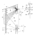
図1は本発明に係る壁面照明器具の一実施形態の一部を破断して示した斜視図、図2は図1のB−B断面図、図3は図2に示した絶縁カバー部材の拡大斜視図、図4は図3のC部の拡大図、図5は図1に示した壁面照明器具を部屋の側壁面を照明するべく床壁に配置した時に、該壁面照明器具の反射光の説明図、図6は図5のD矢視図で、図5に示した壁面照明器具の反射面による配光形態の説明図である。
Hereinafter, preferred embodiments of a wall lighting apparatus according to the present invention will be described in detail with reference to the drawings.
FIG. 1 is a perspective view showing a part of an embodiment of a wall lighting apparatus according to the present invention in a cutaway state, FIG. 2 is a sectional view taken along the line BB in FIG. 1, and FIG. 3 is an insulating cover member shown in FIG. 4 is an enlarged view of a portion C in FIG. 3, and FIG. 5 is a diagram showing a reflected light of the wall luminaire when the wall luminaire shown in FIG. 1 is arranged on the floor wall to illuminate the side wall surface of the room. FIG. 6 is a view taken in the direction of arrow D in FIG. 5, and is an explanatory view of a light distribution form by the reflecting surface of the wall surface lighting apparatus shown in FIG. 5.
この一実施形態の壁面照明器具1は、例えば、図5に示す室内空間2において、照明対象である被照明壁面3の一方の端縁(図5では下端縁)側から、該被照明壁面3を照射する。
図5の場合、被照明壁面3は、室内空間2を画成している側壁面である。そして、壁面照明器具1は、被照明壁面3の下端縁から水平方向に延びる床壁5に設置されている。
For example, in the
In the case of FIG. 5, the
なお、以下の実施形態の説明では、被照明壁面3である側壁面の上下方向(図5の矢印Z方向)を被照明壁面3の長さ方向、被照明壁面3である側壁面の水平方向(図6の矢印Y方向)を被照明壁面3の幅方向として、説明を行う。
In the following description of the embodiment, the vertical direction of the side wall surface that is the illuminated wall surface 3 (the direction indicated by the arrow Z in FIG. 5) is the length direction of the
この壁面照明器具1は、図1及び図2に示すように、3個の点光源7が搭載された光源搭載基板11と、該光源搭載基板11を収容した内部絶縁ケース13と、この内部絶縁ケース13の外周囲を覆って照明器具としての外観を提供する外部ケース15とで構成されている。
As shown in FIGS. 1 and 2, the
本実施の形態の場合、3個の点光源7は、発光強度が同一のLED(発光ダイオード)である。
そして、光源搭載基板11は、図2に示すように、被照明壁面3に近い前半側領域11aに点光源7を搭載し、後半側領域11bには点光源7の点灯を制御する各種の回路部品(不図示)を搭載している。
In the present embodiment, the three
As shown in FIG. 2, the light
光源搭載基板11の前半側領域11aは、3個の点光源7を、光軸7aを被照明壁面3の長さ方向(図5の矢印Z方向)に向けた姿勢で搭載している。また、光源搭載基板11上の3個の点光源7は、被照明壁面3の幅方向(図6の矢印Y方向)に所定の離間間隔L1(図6参照)を空けて搭載されている。
The front
内部絶縁ケース13は、図2に示すように、光源搭載基板11の前半側領域11aの上面側表面を覆う第1のカバー部材13aと、該第1のカバー部材13aの後縁に連設されて光源搭載基板11の後半側領域11bの上面側表面を覆う第2のカバー部材13bと、これらのカバー部材13a,13bの周囲に連設されて光源搭載基板11の外周囲を覆う側壁部13cとを、絶縁樹脂材料により一体形成したものである。
内部絶縁ケース13に収容された光源搭載基板11は、不図示のねじ又は凹凸嵌合によって、内部絶縁ケース13の内部に固定されている。
As shown in FIG. 2, the inner
The light
第1のカバー部材13aは、点光源7と対向する位置に、点光源7を露出させる開口13dが設けられている。この開口13dは、点光源7から出射される光をできるだけ弱めずに被照明壁面3側に出力するためのものである。
The
第2のカバー部材13bは、第1のカバー部材13aの後縁から、一段隆起して形成されていて、後半側領域11bの上面側に、該後半側領域11bに搭載された回路部品を収容する部品収容スペース17を画成している。
The
また、第1のカバー部材13aの後縁から隆起する第2のカバー部材13bの前縁部13eは、被照明壁面3側から見て点光源7の背部側の位置(即ち、点光源7を挟んで被照明壁面3とは逆側となる位置)に隆起している。
Further, the
そして、この前縁部13eの外側面(外表面)の内、各点光源7の装備位置の付近は、被照明壁面3とは逆側に各点光源7から出射される光を被照明壁面3に向けて反射する反射面21となっている。
換言すると、本実施の形態の壁面照明器具1では、光源搭載基板11上の各点光源7毎に、被照明壁面3とは逆側に各点光源7から出射される光を被照明壁面3に向けて反射する反射面21が装備されている。また、各反射面21は、第2のカバー部材13bの前縁部13eの外側面により提供されるもので、点光源7を挟んで被照明壁面3とは逆側に位置している。
Then, in the vicinity of the equipment position of each point
In other words, in the
各反射面21は、図3及び図4に示すように、点光源7の光軸7a方向から見て、被照明壁面3に向かって凹となる一対の略V字状反射部22,23により構成されている。
略V字状反射部22は、図4に示すように、点光源7の光軸7a方向から見て、被照明壁面3に向かって凹となる略V字状を構成する2つの反射面22a,22bから構成されている。また、同様に、略V字状反射部23も、点光源7の光軸7a方向から見て、被照明壁面3に向かって凹となる略V字状を構成する2つの反射面23a,23bから構成されている。
As shown in FIGS. 3 and 4, each reflecting
As shown in FIG. 4, the substantially V-shaped reflecting
一対の略V字状反射部22,23は、図6に示すように、各点光源7の中心を通って被照明壁面3に垂直な基準面25に対して対称に並んでいて、反射面21全体としては、点光源7の光軸7a方向から見て略W字形状を呈している。
As shown in FIG. 6, the pair of substantially V-shaped reflecting
前述した各反射部22,23を構成している各反射面22a,22b,23a,23bは、光の反射方向を制御するため、図5に示すように、被照明壁面3の長さ方向(図5の矢印Z方向)に対して所定の傾斜角θが付与されて、後傾姿勢になっていて、反射光を被照明壁面3の長さ方向に拡散させる。
また、前述した各反射部22,23を構成している各反射面22a,22b,23a,23bは、光の反射方向を制御するため、図6に示すように、被照明壁面3の幅方向(図6の矢印Y方向)に対して所定の傾斜角φ1,φ2,φ3,φ4が付与されている。
Each of the reflecting
Further, each of the reflection surfaces 22a, 22b, 23a, and 23b constituting each of the
即ち、前述した各反射部22,23を構成している各反射面22a,22b,23a,23bは、図5及び図6に示すように、被照明壁面3の長さ方向及び幅方向の双方に対して所定の傾斜角θ,φ1,φ2,φ3,φ4を備えることにより、各点光源7から直接被照明壁面3に出射される直接光による被照明壁面3上の照度のばらつきをなくすように、反射光を配光する。
That is, each
具体的に説明すると、各点光源7は、図6に示すように、被照明壁面3上に、直接光B1による照射域S1を形成する。この照射域S1は、点光源7の中心を通って被照明壁面3に直交する各基準面25を中心とする領域である。
点光源7相互の離間間隔を一定以上に広げると、各点光源7が形成する直接光B1による照射域S1相互間に、直接光B1が到達しない暗部領域S2が形成されてしまう。
そこで、各反射面21の略V字状反射部22,23は、図6に示すように、点光源7からその背面側(被照明壁面3とは逆側)に出射された光を、上記の暗部領域S2に拡散配光して、図6に示すように暗部領域S2に重なる様に反射光による照射域S3を形成して、点光源7からの直接光による被照明壁面3上の照度のばらつきをなくす。
Specifically, as shown in FIG. 6, each point
If the distance between the point
Therefore, as shown in FIG. 6, the substantially V-shaped reflecting
また、各反射面21の略V字状反射部22,23は、図5に示したように、被照明壁面3の長さ方向に対する傾斜角θによって、反射光B2を被照明壁面3の長さ方向に拡散配光して、被照明壁面3の長さ方向においても照度のばらつきを低減させる。
Further, as shown in FIG. 5, the substantially V-shaped reflecting
以上に説明した壁面照明器具1では、光源搭載基板11上の点光源7の装備位置に対して、被照明壁面3とは逆側となる各点光源7の背面側には反射面21が装備されていて、これらの各反射面21が、被照明壁面3とは逆側に各点光源7から出射された光を被照明壁面3側に反射する。
そして、上記の反射面21は、被照明壁面3の長さ方向及び幅方向の双方に対して所定の傾斜角θ,φ1,φ2,φ3,φ4を備えることにより、各点光源7から直接被照明壁面3に出射される直接光B1による被照明壁面3上の照度のばらつきをなくすように、反射光B2を配光する。
In the
The reflecting
即ち、各点光源7からの直接光B1が照射される被照明壁面3上の照射域S1間を、反射光B2が補完照射して、被照明壁面3上での照度のばらつきを無くすため、消費電力が小さいLEDによる点光源7から出射された光を、被照明壁面3上のより広範囲な領域に照度にばらつきが生じないように拡散配光することができる。
従って、少数のLED(点光源7)により、被照明壁面3上の広範囲な領域に対する均一照明を実現することができ、照明器具の小型化や低コスト化と、省電力化による電気代の低減を図ることができる。
That is, the reflected light B2 is complementarily irradiated between the irradiation areas S1 on the illuminated
Therefore, a small number of LEDs (point light source 7) can achieve uniform illumination over a wide area on the
また、本実施の形態の壁面照明器具1では、各点光源7毎に装備された反射面21は、点光源7の光軸7a方向から見て、被照明壁面3に向かって凹となる一対の略V字状反射部22,23が各点光源7の中心を通って被照明壁面3に垂直な基準面25に対して対称に並ぶことで、略W字形状を呈しており、それぞれの略V字状反射部22,23が、点光源7からの直接光B1による被照明壁面3上の照度のばらつきをなくすように、反射光B2を拡散配光する。
即ち、略W字形状を構成している一対の略V字状反射部22,23は、それぞれ、点光源7から出射される直接光B1による被照明壁面3上の照射域(直接光B1照射域)に対して、その幅方向の外側に、反射光B2による照射域(反射光B2照射域)を形成する。
Moreover, in the wall
That is, each of the pair of substantially V-shaped reflecting
従って、一つの点光源7が略一定の照度で照明することのできる被照明壁面3上の幅方向の照射域が拡張され、隣接する点光源7相互において、それぞれの直接光B1照射域の間が反射光B2照射域で埋まる様に、隣接する点光源7間の離間間隔を設定しておけば、被照明壁面3の幅方向に連続して、照度にばらつきの無い均一照明を実現することができ、使用する点光源7の数量を最小限に抑えて、装置の小型化や低コスト化を図ることができる。
Therefore, the irradiation area in the width direction on the illuminated
なお、略V字状反射部22,23を構成している各反射面22a,22b,23a,23bは、被照明壁面3の長さ方向にも傾斜していて、被照明壁面3の長さ方向に対しても、照度を調整する拡散配光を行う。
従って、被照明壁面3の長さ方向にもより広範囲に渡って、照度にばらつきの無い良好な照明を実現することができる。
In addition, each
Accordingly, it is possible to realize good illumination with no variation in illuminance over a wider range in the length direction of the
また、本実施の形態の壁面照明器具1の場合、各反射面21は、各点光源7の背面側に位置する第2のカバー部材13bの外側面により提供されている。
従って、反射面21を専用の部品で構成する必要が無くなり、部品の共用による部品点数の削減により、機器の構成の簡略化や、コストの低減を図ることができる。
Moreover, in the case of the wall
Therefore, it is not necessary to configure the reflecting
なお、本発明に係る壁面照明器具において、光源搭載基板11上に配列する点光源7の具体的な配列数等は、上記実施の形態に限らない。
装備する点光源7の配列数は、照明する被照明壁面の寸法等に応じて適宜に調整すると良い。
また、本発明に係る壁面照明器具で使用する点光源としては、消費電力が小さく、発光強度の高いLEDを使用することが望ましいが、LED以外の豆球を点光源として利用することも考えられる。
In addition, in the wall surface lighting fixture which concerns on this invention, the specific number of arrangement | sequences etc. of the point
The number of arrangement of the point
Moreover, although it is desirable to use LED with low power consumption and high light emission intensity as a point light source used with the wall surface illuminator according to the present invention, it is also conceivable to use a bean bulb other than LED as a point light source. .
1 壁面照明器具
3 被照明壁面
5 床壁
7 点光源
7a 光軸
11 光源搭載基板
11a 前半側領域
11b 後半側領域
13 内部絶縁ケース
13a 第1のカバー部材
13b 第2のカバー部材
13c 側壁部
13d 開口
13e 前縁部
15 外部ケース
17 部品収容スペース
21 反射面
22,23 略V字状反射部
22a,22b,23a,23b 反射面
25 基準面
S1,S3 照射域
S2 暗部領域
DESCRIPTION OF
Claims (3)
複数個の点光源が被照明壁面の幅方向に所定の離間間隔を空けて搭載された光源搭載基板と、
上記の各点光源毎に、該当の点光源を挟んで前記被照明壁面とは逆側に配置されて各点光源から出射される光を前記被照明壁面に向けて反射する反射面と、を備え、
前記各反射面は、前記被照明壁面の長さ方向及び幅方向の双方に対して所定の傾斜角を備え、
前記複数個の点光源間の離間間隔は、各点光源から出射される直接光による前記被照明壁面上の照射域の間が前記各反射面で反射される反射光による前記被照明壁面上の照射域で埋まる様に、設定されていることを特徴とする壁面照明器具。 A wall lighting device for illuminating a wall to be illuminated,
A light source mounting board on which a plurality of point light sources are mounted with a predetermined spacing in the width direction of the illuminated wall;
For each of the above point light sources, a reflecting surface that is disposed on the opposite side of the illuminated wall with the corresponding point light source interposed therebetween and reflects light emitted from each point light source toward the illuminated wall surface. Prepared,
Each reflective surface has a predetermined inclination angle with respect to both the length direction and the width direction of the illuminated wall surface ,
The spacing between the plurality of point light sources is such that the interval between the irradiation areas on the illuminated wall surface by the direct light emitted from each point light source is reflected on the illuminated wall surface by the reflected light reflected by the reflecting surfaces. A wall luminaire characterized by being set so as to be buried in the irradiation area .
Priority Applications (1)
| Application Number | Priority Date | Filing Date | Title |
|---|---|---|---|
| JP2007332646A JP5005526B2 (en) | 2007-12-25 | 2007-12-25 | Wall light fixture |
Applications Claiming Priority (1)
| Application Number | Priority Date | Filing Date | Title |
|---|---|---|---|
| JP2007332646A JP5005526B2 (en) | 2007-12-25 | 2007-12-25 | Wall light fixture |
Publications (2)
| Publication Number | Publication Date |
|---|---|
| JP2009158172A JP2009158172A (en) | 2009-07-16 |
| JP5005526B2 true JP5005526B2 (en) | 2012-08-22 |
Family
ID=40961977
Family Applications (1)
| Application Number | Title | Priority Date | Filing Date |
|---|---|---|---|
| JP2007332646A Expired - Fee Related JP5005526B2 (en) | 2007-12-25 | 2007-12-25 | Wall light fixture |
Country Status (1)
| Country | Link |
|---|---|
| JP (1) | JP5005526B2 (en) |
Cited By (1)
| Publication number | Priority date | Publication date | Assignee | Title |
|---|---|---|---|---|
| KR102283478B1 (en) * | 2020-03-27 | 2021-07-29 | 주식회사 크린텍코리아 | Metal Filter |
Family Cites Families (4)
| Publication number | Priority date | Publication date | Assignee | Title |
|---|---|---|---|---|
| JPS58142809U (en) * | 1982-03-23 | 1983-09-26 | トヨタ自動車株式会社 | Lamp housing structure of automotive lamps |
| JP2000285703A (en) * | 1999-03-29 | 2000-10-13 | Hikari Energie Oyo Kenkyusho:Kk | Planar lighting system |
| JP2003059313A (en) * | 2001-08-15 | 2003-02-28 | Koito Mfg Co Ltd | Vehicle lighting |
| JP2007080666A (en) * | 2005-09-14 | 2007-03-29 | Toshiba Lighting & Technology Corp | Wall lighting device |
-
2007
- 2007-12-25 JP JP2007332646A patent/JP5005526B2/en not_active Expired - Fee Related
Cited By (1)
| Publication number | Priority date | Publication date | Assignee | Title |
|---|---|---|---|---|
| KR102283478B1 (en) * | 2020-03-27 | 2021-07-29 | 주식회사 크린텍코리아 | Metal Filter |
Also Published As
| Publication number | Publication date |
|---|---|
| JP2009158172A (en) | 2009-07-16 |
Similar Documents
| Publication | Publication Date | Title |
|---|---|---|
| CN102933898B (en) | Illumination device | |
| JP5071745B2 (en) | Lighting device | |
| RU2459142C1 (en) | Street lamp based on light diodes | |
| EP2916063B1 (en) | Led lighting apparatus | |
| JP2009266780A (en) | Luminous body and luminaire | |
| CN103775872B (en) | Means of illumination | |
| JP2010205482A (en) | Luminaire | |
| JP2009104913A (en) | Lighting fixtures and emergency lights | |
| KR100986782B1 (en) | Flat lighting device using light emitting diode | |
| JP2011204699A (en) | Lighting system | |
| JP5732613B2 (en) | lighting equipment | |
| JP5277939B2 (en) | lighting equipment | |
| JP5005526B2 (en) | Wall light fixture | |
| KR20240175644A (en) | Lighting device with adjustable reflection angle | |
| JP6277604B2 (en) | lighting equipment | |
| JP2018006320A (en) | Light source device | |
| KR20110011847A (en) | Panel-integrated lighting without glare | |
| JP5547003B2 (en) | Floodlight | |
| JP2009283198A (en) | Embedded lighting device | |
| JP2013110030A (en) | Lighting device | |
| JP6457045B2 (en) | lighting equipment | |
| JP2018147563A (en) | LIGHT EMITTING DEVICE AND LIGHTING DEVICE USING THE SAME | |
| JP3156721U (en) | LED lighting device | |
| JP5689370B2 (en) | lighting equipment | |
| JP2008166184A (en) | Lighting device |
Legal Events
| Date | Code | Title | Description |
|---|---|---|---|
| A621 | Written request for application examination |
Free format text: JAPANESE INTERMEDIATE CODE: A621 Effective date: 20100825 |
|
| A977 | Report on retrieval |
Free format text: JAPANESE INTERMEDIATE CODE: A971007 Effective date: 20111222 |
|
| A711 | Notification of change in applicant |
Free format text: JAPANESE INTERMEDIATE CODE: A712 Effective date: 20120111 |
|
| A131 | Notification of reasons for refusal |
Free format text: JAPANESE INTERMEDIATE CODE: A131 Effective date: 20120207 |
|
| A521 | Written amendment |
Free format text: JAPANESE INTERMEDIATE CODE: A523 Effective date: 20120330 |
|
| TRDD | Decision of grant or rejection written | ||
| A01 | Written decision to grant a patent or to grant a registration (utility model) |
Free format text: JAPANESE INTERMEDIATE CODE: A01 Effective date: 20120424 |
|
| A01 | Written decision to grant a patent or to grant a registration (utility model) |
Free format text: JAPANESE INTERMEDIATE CODE: A01 |
|
| A61 | First payment of annual fees (during grant procedure) |
Free format text: JAPANESE INTERMEDIATE CODE: A61 Effective date: 20120523 |
|
| FPAY | Renewal fee payment (event date is renewal date of database) |
Free format text: PAYMENT UNTIL: 20150601 Year of fee payment: 3 |
|
| R150 | Certificate of patent or registration of utility model |
Ref document number: 5005526 Country of ref document: JP Free format text: JAPANESE INTERMEDIATE CODE: R150 Free format text: JAPANESE INTERMEDIATE CODE: R150 |
|
| LAPS | Cancellation because of no payment of annual fees |