JP4992805B2 - Image forming apparatus and image forming control program - Google Patents
Image forming apparatus and image forming control program Download PDFInfo
- Publication number
- JP4992805B2 JP4992805B2 JP2008104401A JP2008104401A JP4992805B2 JP 4992805 B2 JP4992805 B2 JP 4992805B2 JP 2008104401 A JP2008104401 A JP 2008104401A JP 2008104401 A JP2008104401 A JP 2008104401A JP 4992805 B2 JP4992805 B2 JP 4992805B2
- Authority
- JP
- Japan
- Prior art keywords
- image
- correction method
- print medium
- movement
- maximum value
- Prior art date
- Legal status (The legal status is an assumption and is not a legal conclusion. Google has not performed a legal analysis and makes no representation as to the accuracy of the status listed.)
- Expired - Fee Related
Links
Images


Landscapes
- Paper Feeding For Electrophotography (AREA)
- Controlling Sheets Or Webs (AREA)
- Registering Or Overturning Sheets (AREA)
- Accessory Devices And Overall Control Thereof (AREA)
- Record Information Processing For Printing (AREA)
- Laser Beam Printer (AREA)
Abstract
Description
本発明は、画像形成装置及び画像形成制御プログラムに関する。 The present invention relates to an image forming apparatus and an image formation control program.
電子写真方式などの画像形成装置において、用紙と当該用紙上に形成する画像との相対位置(アライメント)を、用紙上の方向であって用紙を搬送する方向と直交する方向(露光装置で静電潜像を光書き込みするときの主走査方向)に合わせる技術としては、レジストローラで用紙をニップした状態で当該レジストローラを基準位置にある用紙センサの位置まで主走査方向に移動させる技術(サイドシフト)が知られている(特許文献1〜4)。 In an image forming apparatus such as an electrophotographic system, the relative position (alignment) between a sheet and an image formed on the sheet is a direction on the sheet that is orthogonal to the direction in which the sheet is transported (static by the exposure device) As a technique for matching the latent image with the main scanning direction when optically writing, a technique for moving the registration roller in the main scanning direction to the position of the paper sensor at the reference position while the paper is nipped by the registration roller (side shift) ) Is known (Patent Documents 1 to 4).
また、露光装置による感光体ドラム上での画像の書き出し位置を変更することにより、主走査方向のアライメントを補正する技術についても知られている(特許文献5)。
用紙などの印刷媒体上に電子写真方式で画像形成を行う複写機、レーザープリンタ等の画像形成装置において、用紙と当該用紙上に形成する画像との相対位置(アライメント)を適切に調整するためには、感光体ドラムへの用紙の搬送方向、すなわち副走査方向(露光装置で静電潜像を光書き込みするときの副走査方向)と、用紙上の方向であって当該搬送方向と直交する方向、すなわち主走査方向(露光装置で静電潜像を光書き込みするときの主走査方向)とのそれぞれにおいて位置合わせをする必要がある。 To appropriately adjust the relative position (alignment) between a sheet and an image formed on the sheet in an image forming apparatus such as a copying machine or a laser printer that forms an image on a printing medium such as a sheet by electrophotography. Is the paper transport direction to the photosensitive drum, that is, the sub-scanning direction (the sub-scanning direction when the electrostatic latent image is optically written by the exposure device), and the direction on the paper and perpendicular to the transport direction. That is, it is necessary to perform alignment in each of the main scanning direction (main scanning direction when the electrostatic latent image is optically written by the exposure apparatus).
また、用紙が常に同じ位置を走行した場合には、用紙搬送ローラや、搬送ベルトが用紙のエッジによって損傷を受ける場合があるため、用紙搬送路や画像形成を行なう位置を主走査方向に適宜ずらしたいという要求があり、主走査方向のアライメントの補正量の増大が必要となる。 In addition, when the paper always travels at the same position, the paper transport roller and the transport belt may be damaged by the edge of the paper. Therefore, the paper transport path and the image forming position are appropriately shifted in the main scanning direction. Therefore, it is necessary to increase the alignment correction amount in the main scanning direction.
副走査方向についてアライメントを補正する手段としては、用紙をプリンタエンジンに搬送するための搬送路上に設けられたレジストローラに対して当該用紙を突き当て、感光体ドラム上で画像が形成されるタイミングに合わせて、当該レジストローラを回転して用紙の先端を当該感光体ドラムに向けて送り出すことにより行うのが一般的である。 As means for correcting the alignment in the sub-scanning direction, the sheet is abutted against a registration roller provided on a conveyance path for conveying the sheet to the printer engine, and the image is formed on the photosensitive drum. In addition, it is generally performed by rotating the registration roller and feeding the leading edge of the sheet toward the photosensitive drum.
また、主走査方向についてアライメントを補正する手段としては、レジストローラで用紙をニップした状態で当該レジストローラを主走査方向に移動させる手段と、露光装置による感光体ドラム上での画像の書き出し位置を主走査方向に移動させる手段とが考えられる。 Further, as means for correcting alignment in the main scanning direction, means for moving the registration roller in the main scanning direction with the paper nipped by the registration roller, and an image writing position on the photosensitive drum by the exposure device. A means for moving in the main scanning direction can be considered.
しかしながら、主走査方向についてアライメントを補正するこれらの手段では、次のような不具合がある。 However, these means for correcting alignment in the main scanning direction have the following problems.
まず、レジストローラを主走査方向に移動させる手段では、主走査方向への補正量は画像形成装置のサイズに左右されてしまい、また、補正量を大きくしようとすると用紙にねじれやダメージが生じてしまうので、補正量には限界がある。 First, in the means for moving the registration roller in the main scanning direction, the correction amount in the main scanning direction depends on the size of the image forming apparatus, and if the correction amount is increased, the paper is twisted or damaged. Therefore, there is a limit to the amount of correction.
また、画像の書き出し位置を移動させる手段では、当該画像形成装置で可能となる画像形成の最大幅により、感光体ドラム上での光書込み位置の補正量に制限を受ける。特に用紙のサイズが大きくて画像幅が大きくなった場合には、光書込み位置の余裕(画像形成の最大幅から画像幅を引いた値)が少なくなる。よって、用紙サイズが大きい場合ほど可能となる主走査方向の補正量が小さくなるという限界がある。 Further, the means for moving the image writing position is limited by the correction amount of the light writing position on the photosensitive drum due to the maximum width of image formation that can be performed by the image forming apparatus. In particular, when the paper size is large and the image width is large, the margin of the optical writing position (the value obtained by subtracting the image width from the maximum width of image formation) is reduced. Therefore, there is a limit that the larger the paper size, the smaller the correction amount in the main scanning direction that is possible.
本発明の目的は、印刷媒体と当該印刷媒体上の画像との相対位置を、印刷媒体上の方向であって印刷媒体を印刷位置に搬送するときの搬送方向と直交する方向に補正するのに際して、その補正量を大きくすることである。 An object of the present invention is to correct the relative position between a print medium and an image on the print medium in a direction on the print medium and a direction orthogonal to the transport direction when the print medium is transported to the print position. The correction amount is increased.
請求項1に記載の発明は、印刷媒体上に画像を形成する作像器と、前記作像器で前記印刷媒体上に画像形成を行なう位置に当該印刷媒体を搬送する搬送路と、前記作像器により前記印刷媒体上の方向であって前記搬送を行なうときの搬送方向と交差する方向に前記印刷媒体自体の移動によらず前記画像形成を行なう位置を変更することにより、前記画像形成を行なう位置での当該印刷媒体と画像との相対的な位置を移動する第1の移動手段と、印刷媒体上の方向であって前記搬送を行なうときの搬送方向と交差する方向に当該印刷媒体を移動することにより、前記画像形成を行なう位置での当該印刷媒体と画像との相対的な位置を移動する第2の移動手段と、前記画像形成を行なう位置に搬送する前の前記印刷媒体の位置を前記搬送路上で検出する位置検出手段と、前記位置検出手段で検出した前記印刷媒体が基準位置から見て前記当該印刷媒体上の方向であって前記搬送を行なうときの搬送方向と交差する方向のずれ量を判定するずれ量判定手段と、印刷媒体のサイズを判定するサイズ判定手段と、第1の移動手段による変更量の最大値である第1の最大値と前記第2の移動手段による前記サイズ判定手段により判定したサイズに応じた変更量の最大値である第2の最大値との合計より前記ずれ量判定手段で判定したずれ量が大きいときに、前記第1の移動手段による移動と前記第2の移動手段による移動を前記印刷媒体上に画像の欠けの発生を許容したまま実行する第1の補正方式を実行する制御手段と、を備えている画像形成装置である。 The invention described in claim 1 is an image forming device that forms an image on a print medium, a conveyance path that conveys the print medium to a position where the image forming device forms an image on the print medium, and the image forming device. The image formation is performed by changing a position where the image formation is performed regardless of movement of the print medium itself in a direction on the print medium by the imager and a direction intersecting the conveyance direction when the conveyance is performed. A first moving means for moving a relative position between the print medium and the image at a position to be performed, and the print medium in a direction intersecting the transport direction when the transport is performed on the print medium. And a second moving means for moving a relative position between the print medium and the image at the position where the image is formed, and a position of the print medium before being conveyed to the position where the image is formed. On the transport path A position detection unit that determines the amount of deviation of the print medium detected by the position detection unit in a direction on the print medium as viewed from a reference position and a direction that intersects the transport direction when the transport is performed Judgment is made by deviation amount determination means, size determination means for determining the size of the print medium, first maximum value that is the maximum value of the change amount by the first moving means, and size determination means by the second moving means. When the shift amount determined by the shift amount determination unit is larger than the total of the second maximum value, which is the maximum value of the change amount according to the size, the movement by the first moving unit and the second movement An image forming apparatus comprising: a control unit that executes a first correction method that executes the movement by the unit while allowing the occurrence of image loss on the print medium .
請求項2に記載の発明は、請求項1に記載の画像形成装置において、前記制御手段は、第1の移動手段による変更量の第1の最大値と前記第2の移動手段によるサイズに応じた変更量の第2の最大値との合計より前記ずれ量判定手段で判定したずれ量が大きいときに前記第1の移動手段による移動と前記第2の移動手段による移動とを前記印刷媒体上に画像の欠けが生じない範囲で実行する第2の補正方式を実行可能で、前記第1の補正方式と前記第2の補正方式のいずれかを選択する選択手段をさらに備え、前記制御手段は、前記選択手段で選択された前記第1の補正方式又は前記第2の補正方式を実行するように制御する。 According to a second aspect of the present invention, in the image forming apparatus according to the first aspect, the control unit responds to a first maximum value of a change amount by the first moving unit and a size by the second moving unit. When the shift amount determined by the shift amount determination unit is larger than the sum of the change amount and the second maximum value, the movement by the first movement unit and the movement by the second movement unit are performed on the print medium. A second correction method that can be executed in a range in which no image is missing, and further includes a selection unit that selects one of the first correction method and the second correction method, and the control unit includes: Then, control is performed so as to execute the first correction method or the second correction method selected by the selection means.
請求項3に記載の発明は、請求項2に記載の画像形成装置において、前記制御手段は、前記ずれ量が前記第1の最大値より大きいときに前記第1の移動手段による移動と前記第2の移動手段による移動とを実行し、前記ずれ量が前記第1の最大値以下であるときは前記第1の移動手段により移動を実行する第3の補正方式と、前記ずれ量が前記第2の最大値より大きいときは前記第1の移動手段による移動と前記第2の移動手段による移動とを実行し、前記ずれ量が前記第2の最大値以下であるときは前記第2の移動手段による移動を実行する第4の補正方式とを実行可能で、前記選択手段は、前記第1の補正方式、前記第2の補正方式、前記第3の補正方式、前記第4の補正方式から補正方式を選択し、前記制御手段は、前記選択手段で選択された前記第1の補正方式、前記第2の補正方式、前記第3の補正方式、又は前記第4の補正方式を実行するように制御する。 According to a third aspect of the present invention, in the image forming apparatus according to the second aspect, when the shift amount is larger than the first maximum value, the control unit moves the first moving unit and the first moving unit. And a third correction method for executing movement by the first moving means when the deviation amount is less than or equal to the first maximum value, and the deviation amount being the first deviation. When it is larger than the maximum value of 2, the movement by the first moving means and the movement by the second moving means are executed, and when the deviation amount is not more than the second maximum value, the second movement is performed. And a fourth correction method for executing movement by means, and the selection means can select from the first correction method, the second correction method, the third correction method, and the fourth correction method. The correction method is selected, and the control means is selected by the selection means. It has been the first correction method, the second correction method, the third correction method, or controls to execute the fourth correction method.
請求項4に記載の発明は、印刷媒体上に画像を形成する作像器と、前記作像器で前記印刷媒体上に画像形成を行なう位置に当該印刷媒体を搬送する搬送路と、前記作像器により前記印刷媒体上の方向であって前記搬送を行なうときの搬送方向と交差する方向に前記印刷媒体自体の移動によらず前記画像形成を行なう位置を変更することにより、前記画像形成を行なう位置での当該印刷媒体と画像との相対的な位置を移動する第1の移動手段と、印刷媒体上の方向であって前記搬送を行なうときの搬送方向と交差する方向に当該印刷媒体を移動することにより、前記画像形成を行なう位置での当該印刷媒体と画像との相対的な位置を移動する第2の移動手段と、前記画像形成を行なう位置に搬送する前の前記印刷媒体の位置を前記搬送路上で検出する位置検出手段と、前記位置検出手段で検出した前記印刷媒体が基準位置から見て前記当該印刷媒体上の方向であって前記搬送を行なうときの搬送方向と交差する方向のずれ量を判定するずれ量判定手段と、印刷媒体のサイズを判定するサイズ判定手段と、を備えている画像形成装置に関して、第1の移動手段による変更量の最大値である第1の最大値と前記第2の移動手段による前記サイズ判定手段により判定したサイズに応じた変更量の最大値である第2の最大値との合計より前記ずれ量判定手段で判定したずれ量が大きいときに、前記第1の移動手段による移動と前記第2の移動手段による移動を前記印刷媒体上に画像の欠けの発生を許容したまま実行する第1の補正方式を実行する制御手段をコンピュータに実行させるコンピュータに読み取り可能な画像形成制御プログラムである。 According to a fourth aspect of the present invention, there is provided an image creator that forms an image on a print medium, a conveyance path that conveys the print medium to a position where the image creator forms an image on the print medium, and the image creator. The image formation is performed by changing a position where the image formation is performed regardless of movement of the print medium itself in a direction on the print medium by the imager and a direction intersecting the conveyance direction when the conveyance is performed. A first moving means for moving a relative position between the print medium and the image at a position to be performed, and the print medium in a direction intersecting the transport direction when the transport is performed on the print medium. And a second moving means for moving a relative position between the print medium and the image at the position where the image is formed, and a position of the print medium before being conveyed to the position where the image is formed. On the transport path A position detection unit that determines the amount of deviation of the print medium detected by the position detection unit in a direction on the print medium as viewed from a reference position and a direction that intersects the transport direction when the transport is performed With respect to an image forming apparatus including a deviation amount determination unit and a size determination unit that determines the size of a print medium, a first maximum value that is a maximum amount of change by a first movement unit and the second value When the shift amount determined by the shift amount determination unit is larger than the sum of the second maximum value that is the maximum value of the change amount according to the size determined by the size determination unit by the shift unit, the first movement A computer that executes control means for executing a first correction method that executes movement by means and movement by the second movement means while allowing image loss on the print medium. The image forming control program readable data.
請求項5に記載の発明は、請求項4に記載の画像形成制御プログラムにおいて、前記制御手段は、第1の移動手段による変更量の第1の最大値と前記第2の移動手段によるサイズに応じた変更量の第2の最大値との合計より前記ずれ量判定手段で判定したずれ量が大きいときに前記第1の移動手段による移動と前記第2の移動手段による移動とを前記印刷媒体上に画像の欠けが生じない範囲で実行する第2の補正方式を実行可能で、前記第1の補正方式と前記第2の補正方式のいずれかを選択する選択手段をさらにコンピュータに実行させ、前記制御手段は、前記選択手段で選択された前記第1の補正方式又は前記第2の補正方式を実行するように制御するようにしている。According to a fifth aspect of the present invention, in the image formation control program according to the fourth aspect, the control means sets the first maximum value of the amount of change by the first moving means and the size by the second moving means. When the deviation amount determined by the deviation amount determination unit is larger than the sum of the corresponding change amount and the second maximum value, the movement by the first movement unit and the movement by the second movement unit are performed on the print medium. A second correction method that can be executed in a range in which no image defect occurs on the computer, and causing the computer to further execute selection means for selecting one of the first correction method and the second correction method, The control means controls to execute the first correction method or the second correction method selected by the selection means.
請求項6に記載の発明は、請求項5に記載の画像形成制御プログラムにおいて、前記制御手段は、前記ずれ量が前記第1の最大値より大きいときに前記第1の移動手段による移動と前記第2の移動手段による移動とを実行し、前記ずれ量が前記第1の最大値以下であるときは前記第1の移動手段により移動を実行する第3の補正方式と、前記ずれ量が前記第2の最大値より大きいときは前記第1の移動手段による移動と前記第2の移動手段による移動とを実行し、前記ずれ量が前記第2の最大値以下であるときは前記第2の移動手段による移動を実行する第4の補正方式とを実行可能で、前記選択手段は、前記第1の補正方式、前記第2の補正方式、前記第3の補正方式、前記第4の補正方式から補正方式を選択し、前記制御手段は、前記選択手段で選択された前記第1の補正方式、前記第2の補正方式、前記第3の補正方式、又は前記第4の補正方式を実行するように制御するものである。 According to a sixth aspect of the present invention, in the image forming control program according to the fifth aspect, the control unit moves the first moving unit when the deviation amount is larger than the first maximum value, and A third correction method for executing movement by the second moving means, and executing the movement by the first moving means when the deviation amount is equal to or less than the first maximum value; and When it is larger than the second maximum value, the movement by the first moving means and the movement by the second moving means are executed, and when the deviation amount is less than or equal to the second maximum value, And a fourth correction method for executing movement by the moving means, wherein the selection means includes the first correction method, the second correction method, the third correction method, and the fourth correction method. A correction method is selected from the control means, and the control means selects the selection method. The first correction method is selected by means, said second correction method, the third correction method, or is intended to control to execute the fourth correction method.
本発明によれば、画像の欠けの発生を許容しつつも本構成を備えない場合に比べて用紙と画像との相対位置の補正を十分に行うことができる。According to the present invention, it is possible to sufficiently correct the relative position between the sheet and the image as compared with the case where the present configuration is not provided while allowing the occurrence of the missing image.
以下、本発明の一実施の形態について図面を参照して説明する。 Hereinafter, an embodiment of the present invention will be described with reference to the drawings.
図1は、本発明の一実施の形態である画像形成装置の概略構成の説明図であり、図2は、画像形成装置の作像器の斜視図である。 FIG. 1 is an explanatory diagram of a schematic configuration of an image forming apparatus according to an embodiment of the present invention, and FIG. 2 is a perspective view of an image creator of the image forming apparatus.
この画像形成装置1は、電子写真方式で印刷媒体に画像形成を行うレーザープリンタの例であり、筐体内の上部には用紙などの印刷媒体(以下では単に「用紙」ともいう)に対してカラー画像形成を行う作像器(プリンタエンジン)2が設けられている。作像部2は、それぞれY(イエロー)、M(マゼンタ)、C(シアン)、K(ブラック)の各色のトナー画像を形成する画像形成部3Y,3M,3C,3Kが一列に並べて配置されている。
The image forming apparatus 1 is an example of a laser printer that forms an image on a print medium by an electrophotographic method, and an upper portion in a housing is colored against a print medium such as paper (hereinafter also simply referred to as “paper”). An image creator (printer engine) 2 that performs image formation is provided. In the image forming unit 2,
各画像形成部3Y,3M,3C,3Kの基本構成は何れも同一であるため、ここでは代表して画像形成部3Yについて説明する。画像形成部3Yは、感光体ドラム4、感光体ドラム4に静電潜像を光書き込みする露光装置5、感光体ドラム4上の静電潜像をトナーで現像する現像器6、感光体ドラム4上に形成されたトナー画像を中間転写ベルト11上に転写する1次転写ローラ7、この転写後に感光体ドラム4上に残存するトナーを除去するドラムクリーナ8など、電子写真プロセスにより感光体ドラム4上にトナー画像を形成するための周知構成の各機器を備えている(詳細な説明は省略する)。
Since the basic configurations of the
各露光装置5は、光源9の発する光を、ポリゴンミラー10を含む所定の光学系を介して感光体ドラム4に照射することにより、感光体ドラム4上を露光走査して静電潜像を形成する。
Each
画像形成部3Y,3M,3C,3Kの下部には中間転写ベルト11が駆動ローラ12、従動ローラ13により張架されている。中間転写ベルト11は各画像形成部3Y,3M,3C,3Kの1次転写ローラ7と感光体ドラム4との間を順次移動し、中間転写ベルト11上には各画像形成部3Y,3M,3C,3KにおいてそれぞれY、M、C、Kの各色のトナー画像が重ねあわされて転写され、もってフルカラーのトナー画像が形成される。中間転写ベルト11の下側には2次転写ローラ14が設けられていて、中間転写ベルト11上のカラーのトナー画像を用紙の上に転写する。すなわち、2次転写ローラ14の位置が用紙の上に画像を形成する位置となる。ベルトクリーナ15は、2次転写ローラ14で転写後に中間転写ベルト11に残存しているトナーを除去する。
An
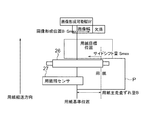
中間転写ベルト11の下部には給紙機構21が設けられている。すなわち、給紙トレイ22には用紙が積層して収納されている。この給紙トレイ22には給紙ローラ23が設けられ、給紙ローラ23の回転により給紙トレイ22の最上層の用紙が搬送ローラ25の回転駆動により用紙搬送経路24を通って作像器2へ搬送される。なお、図1では便宜上給紙トレイ22を1台のみ図示しているが、給紙トレイ22は複数台設けられ、それぞれ異なるサイズの用紙や、同じサイズでも向きの異なる用紙が収納されている。そして、この搬送される用紙の進行方向の先端縁はレジストローラ26のニップ部に突き当てられて一端停止する。そして、2次転写ローラ14上のカラートナー画像の位置にタイミングを合わせてレジストローラ26を回転することにより、2次転写ローラ14上のカラートナー画像の位置と用紙の位置とを合わせるタイミングで用紙が2次転写ローラ14に供給され、用紙上にトナー画像が転写される。レジストローラ26に突き当てられて用紙が一端停止する位置には用紙端センサ27が設けられている。この用紙端センサ27は例えばコンタクトイメージセンサなどにより構成され、用紙上の方向であって用紙の搬送方向とは交差する方向(通常は、用紙上の方向であって用紙の搬送方向とはほぼ直交する方向であり、これは図1において図面方向に垂直な方向)の用紙の端部位置がどこにあるのかを検出する。
A
2次転写ローラ14でカラートナー画像が転写された用紙は搬送経路28を搬送されて定着器29により定着され、排紙トレイ30に排出される。搬送経路31は、定着器29により定着後の用紙を用紙経路32に導き、ここで用紙の向きをスイッチバックさせて搬送経路33に搬出することにより用紙の面を逆にして、搬送経路33により用紙を再び2次転写ローラ14に戻す。これにより用紙の両面印刷が可能となる。
The sheet on which the color toner image has been transferred by the
図3〜図5は、レジストローラ26に設けられたサイドシフト機構49の構成を説明する説明図である。
3 to 5 are explanatory views for explaining the configuration of the
レジストローラ26を構成する一対のローラ26a,26bのそれぞれの回転軸41,42は、その軸方向、回転方向の動きを妨げられることなく軸支されていて、回転軸41、42の各一端には係合部材43,44が設けられている。この係合部材43と44とは互いに係合している。回転軸42の他端にはラック部材45が設けられ、コイルバネ48は(図4)、ラック部材45の歯45aとピニオンギア46の歯46aとの噛み合いにおいて常に同じ歯面同士を接触させ(図5)、もってバックラッシュを防ぐようにラック部材45を付勢している。ステッピングモータで構成されるサイドシフトモータ47はピニオンギア46を回転駆動し、これによりラック部材45が移動し、もってローラ26aが移動して、係合部材43,44を介してローラ26bも同方向に移動する。このときの移動方向は用紙の面方向であって用紙搬送経路24で用紙を搬送する方向と交差する方向(通常は用紙搬送経路24で用紙を搬送する方向とほぼ直交する方向であり、当該方向は各露光装置5のほぼ主走査方向である)である。これにより、レジストローラ26に挟持された用紙は用紙の面方向であって用紙搬送経路24で用紙を搬送する方向と交差する(ほぼ直交する)方向にアライメントの補正がされる。なお、符号48はレジストローラ26を回転駆動させるレジストローラ駆動モータである。
The
図6は、画像形成装置1の電気的な接続を示すブロック図である。 FIG. 6 is a block diagram showing electrical connection of the image forming apparatus 1.
制御部51は、マイクロコンピュータを備え、画像形成装置1の各部を集中的に制御する。制御部51には、各種センサ52(前述の用紙端センサ27その他の画像形成装置1で使用する各種センサを、便宜上、各種センサ52として包括的に図示している)と、各種アクチュエータ53(前述のサイドシフトモータ47、レジストローラ駆動モータ46その他の画像形成装置1で使用する各種アクチュエータを、便宜上、各種アクチュエータ53として包括的に図示している)と、タッチパネルや各種操作ボタンを備えた操作パネル54と、LANその他のネットワークを介し、あるいは、直接にパソコンなどの外部の機器等と通信を行う通信インターフェイス(I/F)55と、画像形成装置1で画像形成するための画像データが一時的に格納される画像メモリ60と、が接続されている。
The
制御部51は、各種演算を行い、各部を集中制御するCPU56を備え、CPU56には、CPU56の作業エリアとなるRAM57と、CPU56が実行する各種の制御プログラムからなる画像形成制御プログラム58や各種固定データが格納されたROM59とが接続されている。
The
画像形成制御プログラム58は、後述する画像形成装置1が実行する特徴的な制御処理を行うためのプログラムであるが、当初から画像形成装置1にセットアップされているか、あるいは、後発的に通信I/F55などを介して外部機器から搬送波の形態で受信し、ROM59を構成する不揮発性メモリや図示しない磁気記憶装置などにセットアップするようにしてもよい。
The image forming
各露光装置5は、感光体ドラム4上での静電潜像の形成位置を用紙の面方向であって用紙搬送経路24で用紙を搬送する方向と交差する方向(通常は用紙の面方向であって用紙搬送経路24で用紙を搬送する方向とほぼ直交する方向であり、当該方向は各露光装置5のほぼ主走査方向である)に補正するようなアライメントの補正を行うことができる。以下では、その具体的な手段について複数例説明する。
Each
図7〜図10は、画像メモリ60に用意されているラインメモリのアドレス構成について説明する説明図である。
7 to 10 are explanatory diagrams for explaining the address configuration of the line memory prepared in the
図7に示すように、このラインメモリ61は、感光体ドラム4を露光走査する主走査1ライン分の画像データを記憶する記憶領域で、1つのアドレスに1画素(例えば600dpi)分の画像データが格納される。ラインメモリ61はこの例ではアドレス000hから1FFFhまであり、ラインメモリ61の1ライン分の画像データの書込開始のアドレスは000hであり、露光装置5による1ライン分の画像データの読み込み開始アドレスも000hである。
As shown in FIG. 7, the
図8は、用紙の面方向であって用紙搬送経路24で用紙を搬送する方向とほぼ直交する方向に静電潜像の形成する位置を移動することでアライメントの補正しない場合の主走査1ライン分の画像データ62をラインメモリ61に記憶した状態を示している。
FIG. 8 shows one main scanning line in the case where the alignment is not corrected by moving the position where the electrostatic latent image is formed in the surface direction of the paper and in a direction substantially perpendicular to the direction of transporting the paper in the
この場合は、図8に示すように、送信されてくる画像データの幅(用紙の面方向であって用紙搬送経路24で用紙を搬送する方向とほぼ直交する方向の幅)に応じて、当該画像データの画像の中央をラインメモリ61の中心のアドレスに合わせるような書込み開始アドレスを選択して画像データを書き込む。図8の例では、幅が4096画素(約173mm)の画像データを格納するものであり、画像データの書込開始アドレスは“(8192−画像データ幅)÷2=2048”となる。露光装置5による読み取り開始アドレスは常に000hから開始され、露光装置5はラインメモリ61の中心アドレスが露光走査位置の中心となるように制御する。このため、画像は感光体ドラム4の露光走査可能位置の中央に形成されることとなる。
In this case, as shown in FIG. 8, according to the width of the transmitted image data (the width in the surface direction of the paper and the direction substantially perpendicular to the direction of transporting the paper in the paper transport path 24), The image data is written by selecting a write start address that matches the center of the image of the image data with the center address of the
図9は、用紙の面方向であって用紙搬送経路24で用紙を搬送する方向とほぼ直交する方向に静電潜像の形成する位置を移動することでアライメントの補正をする場合の主走査1ライン分の画像データ62をラインメモリ61に記憶した状態を示している。
FIG. 9 shows main scanning 1 in the case where the alignment correction is performed by moving the position where the electrostatic latent image is formed in the surface direction of the sheet and in a direction substantially perpendicular to the direction in which the sheet is conveyed on the
画像データの書き込み開始アドレスは、画像データの幅(用紙の面方向であって用紙搬送経路24で用紙を搬送する方向とほぼ直交する方向の幅)から決定される基準位置“(8192−画像データ幅)÷2=2048”に加え、画像形成位置を補正する量のアドレス分(この例で018h(24))を加味した2024となる。露光装置5による読み取り開始アドレスは常に000hからとなり、露光装置5はラインメモリ61のアドレスの中心が、露光範囲の中心となるように制御されているため、この例では、図8の場合に比べて画像の露光範囲の中央から約1mm左にずれた位置に画像が形成されることになる。
The write start address of the image data is a reference position “(8192-image data) determined from the width of the image data (width in the surface direction of the paper and the direction substantially perpendicular to the direction of transporting the paper in the paper transport path 24). In addition to (width) ÷ 2 = 2048 ”, it is 2024 in consideration of the address for correcting the image forming position (in this example, 018h (24)). Since the reading start address by the
図10は、用紙の面方向であって用紙搬送経路24で用紙を搬送する方向とほぼ直交する方向に静電潜像の形成する位置を移動することでアライメントの補正をする場合の主走査1ライン分の画像データ62をラインメモリ61に記憶した状態の他の例について示している。
FIG. 10 shows main scanning 1 in the case where the alignment correction is performed by moving the position where the electrostatic latent image is formed in the surface direction of the sheet and in a direction substantially perpendicular to the direction of conveying the sheet in the
この例では、1つのアドレスに1画素(600dpi)分の画像データが格納される。画像データ書き込みアドレスは、送信されてくる画像データの幅(用紙の面方向であって用紙搬送経路24で用紙を搬送する方向とほぼ直交する方向の幅)に応じて、画像の中央をラインメモリ61の中心アドレスに合わせるような書き込み開始アドレスが選択される。ここで露光装置5による読み取り開始アドレスを、この例の補正量である24だけずらす。露光装置5は読み取ったデータ量が4096画素分になる位置が露光中心となるように調整されるため、この例では、画像の露光走査可能な範囲の中央から約1mm左にずれた位置に画像が形成される。
In this example, image data for one pixel (600 dpi) is stored in one address. The image data write address is a line memory that stores the center of the image in accordance with the width of the transmitted image data (the width in the surface direction of the paper and in the direction substantially perpendicular to the direction of paper conveyance in the paper conveyance path 24). A write start address that matches the center address of 61 is selected. Here, the reading start address by the
以上の図9、図10の例のような補正をすべての主走査ラインについて同様に行なうことにより、画像の露光可能な範囲の中央から所定長さ分だけ左又は右にずれた位置に画像を形成することができる。 9 and 10 is similarly performed for all main scanning lines, the image is shifted to the left or right by a predetermined length from the center of the image exposure range. Can be formed.
このように、図9の例のようにラインメモリ61の画像データの書き込みアドレスの調整又は図10の例のようにラインメモリ61の画像データの読み込みアドレスの調整を行うことにより、用紙の面方向であって用紙搬送経路24で用紙を搬送する方向と交差する方向(通常は、前述のとおり、用紙の面方向であって用紙搬送経路24で用紙を搬送する方向とほぼ直交する方向)に画像の形成位置を容易に補正することができる。
Thus, by adjusting the write address of the image data in the
また、露光装置5で光源9から光を発するタイミングを所望の時間だけ早くあるいは遅くすることによっても同様の補正を行うことができる。
The same correction can also be performed by making the
図11、図12は、画像形成制御プログラム58に基づいて制御部51が実行する処理について説明するフローチャートである。
FIG. 11 and FIG. 12 are flowcharts for explaining processing executed by the
ここで説明する処理では、図7〜図10を参照して説明した画像を形成する位置を補正することにより、用紙の面方向であって用紙搬送経路24で用紙を搬送する方向とほぼ直交する方向のアライメントの補正を行う手段と(以下では第1の補正という)、図3〜図5を参照して説明したサイドシフト機構49により用紙の位置を補正することにより、用紙の面方向であって用紙搬送経路24で用紙を搬送する方向とほぼ直交する方向のアライメントの補正を行う手段と(以下では第2の補正という)を適宜同時に使用して適切なアライメントの補正を行うものである。
In the processing described here, by correcting the position at which the image described with reference to FIGS. 7 to 10 is corrected, the surface direction of the paper and substantially orthogonal to the direction of transporting the paper in the
図11は、この場合に、使用者の必要性に応じて、第1モード及び第2モードの一方を選択し、また、第3モード及び第4モードの一方を選択するための処理である。 FIG. 11 shows a process for selecting one of the first mode and the second mode and selecting one of the third mode and the fourth mode according to the user's need in this case.
まず、制御部51は、操作パネル54の操作により第1モード又は第2モードの選択の実行が要求されたときは(ステップS1のY)、図示しない第1モード/第2モード選択画面をタッチパネルに表示し(ステップS2)、タッチパネルの操作により第1モードが選択されたときは(ステップS3のY)、第1モードをROM59の不揮発性メモリなどに設定し(ステップS4)、第2モードが選択されたときは(ステップS5のY)、第2モードをROM59の不揮発性メモリなどに設定する(ステップS6)。
First, when the execution of selection of the first mode or the second mode is requested by the operation of the operation panel 54 (Y in step S1), the
第1モードは、第2の補正に比べて精度の高いアライメントの補正が可能となる第1の補正を中心に使用してアライメントの補正を行う画質優先モードである。よって、画質を優先して画像形成を行ないたい場合に使用する。第2のモードは、第1の補正に比べて印刷の生産性(高速印刷性)を高く維持したままアライメントの補正が可能となる第2の補正を中心に使用してアライメントの補正を行う速度優先モードである。よって、印刷の生産性を落としたくない場合に使用する。 The first mode is an image quality priority mode in which alignment correction is performed mainly using the first correction that enables alignment correction with higher accuracy than the second correction. Therefore, it is used when it is desired to form an image with priority on image quality. The second mode is a speed at which alignment correction is performed mainly using the second correction that enables alignment correction while maintaining high printing productivity (high-speed printability) compared to the first correction. It is a priority mode. Therefore, it is used when it is not desired to reduce printing productivity.
操作パネル54の操作により第3モード又は第4モードの選択の実行が要求されたときは(ステップS7のY)、図示しない第3モード/第4モード選択画面をタッチパネルに表示し(ステップS8)、タッチパネルの操作により第3モードが選択されたときは(ステップS9のY)、第3モードをROM59の不揮発性メモリなどに設定し(ステップS10)、第4モードが選択されたときは(ステップS11のY)、第1モードをROM59の不揮発性メモリなどに設定する(ステップS12)。 When execution of the selection of the third mode or the fourth mode is requested by operating the operation panel 54 (Y in step S7), a third mode / fourth mode selection screen (not shown) is displayed on the touch panel (step S8). When the third mode is selected by operating the touch panel (Y in step S9), the third mode is set to the nonvolatile memory of the ROM 59 (step S10), and when the fourth mode is selected (step S10). (Y of S11), the first mode is set to the nonvolatile memory of the ROM 59 (step S12).
第3モード、第4モードは、用紙のサイズが大きいために、第1の補正と第2の補正を同時に使用してアライメントの補正を十分に実行しようとすると用紙上に形成される画像に欠けが生じてしまう場合に、アライメントを優先するか、画像の欠けの発生の防止を優先するかを選択するためのモードである。すなわち、第3モードはアライメントの補正が十分に行なわれなくても、画像の欠けが発生することを防止することを優先する画像優先モードであり、第4モードはアライメントの補正が十分に行なわれることを優先し、画像の欠けが発生することを許容するアライメント優先モードである。 In the third mode and the fourth mode, since the size of the paper is large, if the first correction and the second correction are used simultaneously to perform sufficient alignment correction, the image formed on the paper is missing. Is a mode for selecting whether to give priority to alignment or to prevent the occurrence of image loss. That is, the third mode is an image priority mode in which priority is given to preventing occurrence of image loss even if alignment correction is not sufficiently performed, and the fourth mode is sufficient for alignment correction. This is an alignment priority mode that gives priority to the above and allows the occurrence of image loss.
図12は、前述の第1モード又は第2モード、及び、第3モード又は第4モードがそれぞれ設定されていることを前提に、用紙の面方向であって用紙搬送経路24で用紙を搬送する方向と直交する方向のアライメントの補正を行う処理である。
In FIG. 12, the sheet is transported through the
まず、印刷ジョブ実行の要求があったときは(ステップS21のY)、給紙トレイ22から用紙を取り出してレジストローラ26の位置まで搬送して、用紙端センサ27で当該用紙の面方向であって用紙搬送経路24で用紙を搬送する方向と直交する方向(露光装置5の露光走査における主走査方向)のずれ量Aを検出する(ステップS22)。そして、第1の補正により当該主走査方向にアライメントの補正が可能な補正量の最大値Imaxと、第2の補正により当該主走査方向にアライメントの補正が可能な補正量の最大値Smaxとの合計値“Imax+Smax”と、ステップS22で検出したずれ量Aとを比較する(ステップS23)。
First, when there is a request for execution of a print job (Y in step S21), the sheet is taken out from the
ステップS23の比較の結果、“A>Imax+Smax”であるときは(ステップS24のY)、用紙が画像形成サイズの上限に近いサイズであって、画像幅が大きくなり、画像の書き出し位置を第1の補正により大きく動かしたときに画像の端が画像形成可能領域から外れてしまい、画像の一部が欠けてしまうため、アライメントの十分な補正が不可能となる場合である。 If “A> Imax + Smax” as a result of the comparison in step S23 (Y in step S24), the paper is the size close to the upper limit of the image formation size, the image width is increased, and the image writing position is set to the first position. This is a case where the edge of the image deviates from the image formable area when the image is moved largely by the correction, and a part of the image is lost, so that the alignment cannot be sufficiently corrected.
この場合に、第3のモードが設定されているときは(ステップS25のY)、画像の欠けが生じない範囲で第1の補正及び第2の補正の併用によりアライメントの補正を行う(ステップS26)。よって、この場合には、画像の欠けは生じないが、アライメントの補正は不十分なものとなり、用紙上の画像が用紙に対して主走査方向にずれる。 In this case, when the third mode is set (Y in step S25), alignment correction is performed by combining the first correction and the second correction within a range in which no image is lost (step S26). ). Therefore, in this case, the image is not missing, but the alignment correction is insufficient, and the image on the sheet is shifted in the main scanning direction with respect to the sheet.
また、第4のモードが設定されているときは(ステップS25のN)、画像の欠けが生じても第1の補正及び第2の補正の併用によりアライメントの補正を十分に行う(ステップS27)。よって、この場合には、アライメントの補正は十分に行われるが、画像の欠けが発生する。このようなアライメントの補正量の足りなくなるような用紙サイズでは用紙を断裁して用いることが多いので、このような画像端が多少欠けていても問題ない場合には第4モードを使用する。 When the fourth mode is set (N in step S25), even if the image is missing, the alignment correction is sufficiently performed by the combined use of the first correction and the second correction (step S27). . Therefore, in this case, alignment correction is sufficiently performed, but image loss occurs. In such a paper size that the alignment correction amount is insufficient, the paper is often cut and used. Therefore, if there is no problem even if such an image edge is somewhat missing, the fourth mode is used.
一方、ステップS23の比較の結果、“A≦Imax+Smax”であるときは(ステップS24のN)、第1の補正、第2の補正により画像の欠けが生じることなく、アライメントの補正を十分に行うことができる。 On the other hand, if “A ≦ Imax + Smax” as a result of the comparison in step S23 (N in step S24), the first correction and the second correction sufficiently perform alignment correction without causing image loss. be able to.
この場合に、第1のモードが設定されているときは(ステップS28のY)、ずれ量Aと最大値Imaxとを比較する(ステップS29)。そして、“A≦Imax”であるときは(ステップS30のY)、第1の補正のみによりアライメントの補正を行う(ステップS32)。また、“A>Imax”であるときは(ステップS30のN)、第1の補正、第2の補正を併用することによりアライメントの補正を行う(ステップS32)。すなわち、第1の補正は、アライメント補正の精度は高いので画質は良いが、アライメントのずれ量を検出する前に画像形成を開始することが不可能になるため印刷の生産性が悪い(印刷速度が低い)ので、印刷の生産性より画質を重視する第1のモードでは、第1の補正のみによりアライメントの補正が十分に行なえるときには(ステップS30のY)、第1の補正のみによりアライメントの補正を行うものである(ステップS31)。 In this case, when the first mode is set (Y in step S28), the deviation A is compared with the maximum value Imax (step S29). When “A ≦ Imax” is satisfied (Y in step S30), the alignment is corrected only by the first correction (step S32). If “A> Imax” (N in step S30), the alignment correction is performed by using the first correction and the second correction together (step S32). In other words, the first correction has good image quality because the accuracy of alignment correction is high, but it is impossible to start image formation before detecting the amount of misalignment, and printing productivity is poor (printing speed). Therefore, in the first mode in which the image quality is more important than the productivity of printing, when the alignment can be sufficiently corrected only by the first correction (Y in step S30), the alignment can be performed only by the first correction. Correction is performed (step S31).
一方、第2のモードが設定されているときは(ステップS28のN)、ずれ量Aと最大値Smaxとを比較する(ステップS33)。そして、“A≦Smax”であるときは(ステップS34のY)、第2の補正のみによりアライメントの補正を行なう(ステップS35)。また、“A>Imax”であるときは(ステップS34のN)、第1の補正、第2の補正を併用することによりアライメントの補正を行う(ステップS36)。すなわち、第2の補正は、用紙のずれ量Aを観ながら、用紙を主走査方向に移動させるものであり、印刷の生産性に影響は与えないが精度が悪く画質は第1の補正より劣るので、印刷の生産性を画質より重視する第2のモードでは、第2の補正のみによりアライメントの補正が十分に行なえるときには(ステップS34のY)、第2の補正のみによりアライメントの補正を行うものである(ステップS35)。 On the other hand, when the second mode is set (N in step S28), the deviation A is compared with the maximum value Smax (step S33). When “A ≦ Smax” is satisfied (Y in step S34), the alignment is corrected only by the second correction (step S35). If “A> Imax” (N in step S34), the alignment correction is performed by using the first correction and the second correction together (step S36). That is, the second correction is to move the paper in the main scanning direction while observing the paper shift amount A, and does not affect the printing productivity, but the accuracy is poor and the image quality is inferior to the first correction. Therefore, in the second mode in which printing productivity is more important than image quality, when the alignment can be sufficiently corrected only by the second correction (Y in step S34), the alignment is corrected only by the second correction. (Step S35).
なお、図12の処理において、第1のモード、第2のモード、第3のモード、又は第4のモードで前述のとおりアライメントの補正が行なって画像形成を行うときは、操作パネル54のタッチパネルなどに、実行されるモードの種類を表示するなどして使用者に報知し、注意を喚起するようにする。 In the process of FIG. 12, when the image is formed by performing the alignment correction as described above in the first mode, the second mode, the third mode, or the fourth mode, the touch panel of the operation panel 54 is used. For example, the type of the mode to be executed is displayed to notify the user and call attention.
次に、図13〜図17を参照して図12の処理について具体的に説明する。図13〜図17はいずれも用紙Pに画像形成するときのアライメントの補正の様子を示す平面図であり、これらの図において、“画像形成可能幅W”は、画像形成装置1で画像形成可能な主走査方向の最大幅を示し、“画像幅”は、用紙上に形成される画像の幅を示している。“用紙主走査ずれ量”は用紙Pの主走査方向へのずれ量を示している。“用紙基準位置”は“画像形成可能幅W”の幅の中央位置であり、用紙端センサ27の検出に基づいて用紙Pの主走査方向の中央位置がどの程度主走査方向にずれているかを判断する基準となる。“用紙搬送方向”は用紙Pを搬送する方向を矢印で示している。“画像形成位置”は第1の補正による補正量を示し、“サイドシフト量”は第2の補正による補正量を示している。
Next, the processing of FIG. 12 will be specifically described with reference to FIGS. FIGS. 13 to 17 are plan views showing how the alignment is corrected when an image is formed on the paper P. In these drawings, the “image formable width W” indicates that the image forming apparatus 1 can form an image. The maximum width in the main scanning direction is indicated, and “image width” indicates the width of the image formed on the paper. “Paper main scanning deviation amount” indicates the deviation amount of the paper P in the main scanning direction. The “paper reference position” is the center position of the “image formable width W”, and how much the center position of the paper P in the main scanning direction is shifted in the main scanning direction based on the detection of the
図13は、第1のモードで第1の補正のみによりアライメントの補正を行う場合の説明図である。この場合は、第1のモードで、“A≦Imax”の場合に、第1の補正により画像の書き出し位置をAだけ補正するものである。これにより用紙主走査ずれ量(A)だけずれた用紙Pに画像の書き出し位置の補正後の画像幅が合致し、アライメントの補正がなされる。 FIG. 13 is an explanatory diagram in the case where the alignment correction is performed only by the first correction in the first mode. In this case, in the first mode, when “A ≦ Imax”, the image writing position is corrected by A by the first correction. As a result, the image width after the correction of the image writing position matches the sheet P shifted by the sheet main scanning shift amount (A), and the alignment is corrected.
図14は、第2のモードで第2の補正のみによりアライメントの補正を行う場合の説明図である。この場合は、第2のモードで、“A≦Smax”の場合に、用紙主走査ずれ量(A)だけずれた用紙Pに対して第2の補正により用紙の位置をAだけ補正する(サイドシフト量(A))ものである。これにより用紙主走査ずれ量(A)だけずれた用紙Pが“用紙目標位置”に位置補正され、用紙Pの位置と画像幅とが合致し、アライメントの補正がなされる。 FIG. 14 is an explanatory diagram in the case of performing alignment correction only by the second correction in the second mode. In this case, in the second mode, when “A ≦ Smax”, the position of the sheet is corrected by A by the second correction for the sheet P shifted by the sheet main scanning shift amount (A) (side Shift amount (A)). As a result, the paper P shifted by the paper main scanning deviation amount (A) is corrected to the “paper target position”, the position of the paper P matches the image width, and the alignment is corrected.
図15は、第1のモード、第2のモードで第1の補正と第2の補正とを併用してアライメントの補正を行う場合の説明図である。この場合は、第1のモード又は第2のモードで、“A≦Imax”、“A≦Smax”の場合に、用紙主走査ずれ量(B)に対して、第1の補正、又は第2の補正単独では十分にアライメントの補正が出来ないので、第2の補正により補正可能な最大値のSmaxだけ補正し、第1の補正により画像形成位置“B−Smax”だけ補正して、全体として用紙主走査ずれ量(B)を解消するようにアライメントの補正を行う。 FIG. 15 is an explanatory diagram in a case where the alignment correction is performed by using both the first correction and the second correction in the first mode and the second mode. In this case, in the first mode or the second mode, when “A ≦ Imax” and “A ≦ Smax”, the first correction or the second correction is made for the paper main scanning deviation amount (B). Since the alignment correction cannot be sufficiently performed by the correction alone, only the maximum value Smax that can be corrected by the second correction is corrected, and only the image forming position “B-Smax” is corrected by the first correction. The alignment is corrected so as to eliminate the paper main scanning deviation amount (B).
なお、この場合に第1の補正により補正可能な最大値のImaxだけ補正し、第2の補正により画像形成位置“B−Imax”だけ補正するようにしてもよい。この場合には、極力第1の補正によりアライメントの補正を行うことになるので、アライメント補正の精度の低下を最低限にとどめ、画質の低下を抑制することができる。 In this case, only the maximum value Imax that can be corrected by the first correction may be corrected, and only the image forming position “B-Imax” may be corrected by the second correction. In this case, since the alignment correction is performed by the first correction as much as possible, the deterioration of the accuracy of the alignment correction can be minimized and the deterioration of the image quality can be suppressed.
図16は、第3のモードで第1の補正と第2の補正とを併用してアライメントの補正を行う場合の説明図である。第1の補正及び第2の補正を併用しても十分にアライメントの補正が出来ない用紙主走査ずれ量(B)に対して、第2の補正によりサイドシフト量(A)だけ補正して用紙Pを用紙目標位置に移動させ、第1の補正により画像形成位置(C)だけ補正して、画像形成可能幅Wから画像幅がはみ出さないようにし、アライメントはずれても画像の欠けは生じないようにしている。 FIG. 16 is an explanatory diagram in the case where the alignment correction is performed using the first correction and the second correction in combination in the third mode. With respect to the paper main scanning deviation amount (B) that cannot be sufficiently corrected even if the first correction and the second correction are used together, the paper is corrected by the side shift amount (A) by the second correction. P is moved to the paper target position, and only the image forming position (C) is corrected by the first correction so that the image width does not protrude from the image formable width W. I am doing so.
図17は、第4のモードで第1の補正と第2の補正とを併用してアライメントの補正を行う場合の説明図である。第1の補正及び第2の補正を併用しても十分にアライメントの補正が出来ない用紙主走査ずれ量(B)に対して、第2の補正により補正の最大量であるサイドシフト量(Smax)だけアライメントの補正を行なって用紙Pを用紙目標位置に移動させ、第1の補正により画像形成位置“B−Smax”だけアライメントの補正を行うので、アライメントの補正は完全に行なわれるが、画像幅が前述の画像形成可能幅Wからはみ出してしまい、画像形成可能幅Wが縮小して画像形成可能幅W´になっている。この場合は“欠落”として示しているように、画像形成可能幅W´からはみ出した画像幅が画像の欠落となる。しかし、サイドシフト量を第2の補正が可能な最大量である“Smax”としているので、画像の欠けは最小限に抑制できる。 FIG. 17 is an explanatory diagram in the case where the alignment correction is performed using the first correction and the second correction in combination in the fourth mode. The side shift amount (Smax), which is the maximum amount of correction by the second correction, with respect to the paper main scanning deviation amount (B) in which the alignment cannot be sufficiently corrected even if the first correction and the second correction are used together. ), The sheet P is moved to the sheet target position, and the alignment correction is performed only for the image forming position “B-Smax” by the first correction. The width protrudes from the aforementioned image formable width W, and the image formable width W is reduced to an image formable width W ′. In this case, as shown as “missing”, an image width that protrudes from the image formable width W ′ is a missing image. However, since the side shift amount is set to “Smax”, which is the maximum amount that can be subjected to the second correction, it is possible to suppress image loss to a minimum.
なお、前述の例では、レジストローラ26にサイドシフト機構49を設けているが、他の搬送ローラ25にサイドシフト機構49を設けるようにしてもよい。しかし、レジストローラ26は、用紙上に画像形成を行なう位置(前述の例で、2次転写ローラ14の位置)にもっとも近い位置にある用紙の搬送ローラであるため、他の搬送ローラ25にサイドシフト機構49を設けるのに比べると、サイドシフト機構49によるアライメントの補正後に他の搬送ローラ25やレジストローラ26により搬送されることで用紙の位置がずれてしまうことを防止でき、アライメントの補正正確に行うことができるので、レジストローラ26にサイドシフト機構49を設けることが望ましい。
In the above example, the
また、前述の例では、中間転写ベルト11を用いて中間転写ベルト11に形成したカラートナー画像を用紙上に転写するようにしているが、中間転写ベルト11を用いず、用紙を各画像形成部3Y,3M,3C,3Kの2次転写ローラ14の位置に順次移動させ、この用紙に各画像形成部3Y,3M,3C,3Kで形成したトナー画像を直接転写することにより各色のトナー画像を重ね合わせたカラートナー画像を用紙上に直接形成するようにしても良い。この場合は、各2次転写ローラ14の位置が用紙上に画像形成を行なう位置となる。
In the above example, the color toner image formed on the
さらに、前述の例では、画像形成装置1は電子写真方式で画像形成を行なっているが、インクジェット方式、昇華型熱転写方式、銀塩写真方式、直接感熱記録方式、溶融型熱転写方式などの画像形成装置に本発明を適用するようにしても良い。 Further, in the above-described example, the image forming apparatus 1 performs image formation by an electrophotographic method, but image formation by an ink jet method, a sublimation type thermal transfer method, a silver salt photography method, a direct thermal recording method, a melt type thermal transfer method, or the like. You may make it apply this invention to an apparatus.
1 画像形成装置
2 作像器
14 2次転写ローラ
26 レジストローラ
27 用紙端センサ
49 サイドシフト機構
61 ラインメモリ
DESCRIPTION OF SYMBOLS 1 Image forming apparatus 2
Claims (6)
前記作像器で前記印刷媒体上に画像形成を行なう位置に当該印刷媒体を搬送する搬送路と、
前記作像器により前記印刷媒体上の方向であって前記搬送を行なうときの搬送方向と交差する方向に前記印刷媒体自体の移動によらず前記画像形成を行なう位置を変更することにより、前記画像形成を行なう位置での当該印刷媒体と画像との相対的な位置を移動する第1の移動手段と、
印刷媒体上の方向であって前記搬送を行なうときの搬送方向と交差する方向に当該印刷媒体を移動することにより、前記画像形成を行なう位置での当該印刷媒体と画像との相対的な位置を移動する第2の移動手段と、
前記画像形成を行なう位置に搬送する前の前記印刷媒体の位置を前記搬送路上で検出する位置検出手段と、
前記位置検出手段で検出した前記印刷媒体が基準位置から見て前記当該印刷媒体上の方向であって前記搬送を行なうときの搬送方向と交差する方向のずれ量を判定するずれ量判定手段と、
印刷媒体のサイズを判定するサイズ判定手段と、
第1の移動手段による変更量の最大値である第1の最大値と前記第2の移動手段による前記サイズ判定手段により判定したサイズに応じた変更量の最大値である第2の最大値との合計より前記ずれ量判定手段で判定したずれ量が大きいときに、前記第1の移動手段による移動と前記第2の移動手段による移動を前記印刷媒体上に画像の欠けの発生を許容したまま実行する第1の補正方式を実行する制御手段と、
を備えている画像形成装置。 An imager for forming an image on a print medium;
A transport path for transporting the print medium to a position where image formation is performed on the print medium by the imager;
By changing the position where the image formation is performed regardless of the movement of the print medium itself in the direction on the print medium by the image generator and intersecting the transport direction when the transport is performed. First moving means for moving a relative position between the print medium and the image at a position where formation is performed;
The relative position between the print medium and the image at the position where the image is formed is moved by moving the print medium in a direction on the print medium that intersects the transport direction when the transport is performed. and second moving means for moving,
Position detecting means for detecting the position of the print medium on the conveyance path before being conveyed to the position where the image is formed;
A deviation amount determination means for determining a deviation amount in a direction on the print medium when the print medium detected by the position detection means is viewed from a reference position and intersecting a conveyance direction when the conveyance is performed;
Size determination means for determining the size of the print medium;
A first maximum value that is the maximum value of the change amount by the first moving means, and a second maximum value that is the maximum value of the change amount according to the size determined by the size determining means by the second moving means; When the deviation amount determined by the deviation amount determination unit is larger than the total of the above, the movement by the first movement unit and the movement by the second movement unit are allowed to occur on the print medium. Control means for executing a first correction method to be executed;
An image forming apparatus.
前記第1の補正方式と前記第2の補正方式のいずれかを選択する選択手段をさらに備え、
前記制御手段は、前記選択手段で選択された前記第1の補正方式又は前記第2の補正方式を実行するように制御する、
請求項1に記載の画像形成装置。 The control means is determined by the deviation amount determination means based on the sum of the first maximum value of the change amount by the first movement means and the second maximum value of the change amount according to the size by the second movement means. When the amount of deviation is large, it is possible to execute the second correction method in which the movement by the first moving means and the movement by the second moving means are executed within a range where no image is missing on the print medium. ,
A selection means for selecting either the first correction method or the second correction method;
The control means controls to execute the first correction method or the second correction method selected by the selection means;
The image forming apparatus according to claim 1.
前記選択手段は、前記第1の補正方式、前記第2の補正方式、前記第3の補正方式、前記第4の補正方式から補正方式を選択し、
前記制御手段は、前記選択手段で選択された前記第1の補正方式、前記第2の補正方式、前記第3の補正方式、又は前記第4の補正方式を実行するように制御する、
請求項2に記載の画像形成装置。 The control means executes movement by the first moving means and movement by the second moving means when the deviation amount is larger than the first maximum value, and the deviation amount is the first maximum value. A third correction method for executing movement by the first moving means when the value is equal to or less than a value, and movement by the first moving means and the second when the deviation amount is greater than the second maximum value. And a fourth correction method for executing movement by the second moving means when the amount of deviation is equal to or less than the second maximum value.
The selection means selects a correction method from the first correction method, the second correction method, the third correction method, and the fourth correction method,
The control means controls to execute the first correction method, the second correction method, the third correction method, or the fourth correction method selected by the selection means;
The image forming apparatus according to claim 2.
前記作像器で前記印刷媒体上に画像形成を行なう位置に当該印刷媒体を搬送する搬送路と、
前記作像器により前記印刷媒体上の方向であって前記搬送を行なうときの搬送方向と交差する方向に前記印刷媒体自体の移動によらず前記画像形成を行なう位置を変更することにより、前記画像形成を行なう位置での当該印刷媒体と画像との相対的な位置を移動する第1の移動手段と、
印刷媒体上の方向であって前記搬送を行なうときの搬送方向と交差する方向に当該印刷媒体を移動することにより、前記画像形成を行なう位置での当該印刷媒体と画像との相対的な位置を移動する第2の移動手段と、
前記画像形成を行なう位置に搬送する前の前記印刷媒体の位置を前記搬送路上で検出する位置検出手段と、
前記位置検出手段で検出した前記印刷媒体が基準位置から見て前記当該印刷媒体上の方向であって前記搬送を行なうときの搬送方向と交差する方向のずれ量を判定するずれ量判定手段と、
印刷媒体のサイズを判定するサイズ判定手段と、
を備えている画像形成装置に関して、
第1の移動手段による変更量の最大値である第1の最大値と前記第2の移動手段による前記サイズ判定手段により判定したサイズに応じた変更量の最大値である第2の最大値との合計より前記ずれ量判定手段で判定したずれ量が大きいときに、前記第1の移動手段による移動と前記第2の移動手段による移動を前記印刷媒体上に画像の欠けの発生を許容したまま実行する第1の補正方式を実行する制御手段をコンピュータに実行させるコンピュータに読み取り可能な画像形成制御プログラム。 An imager for forming an image on a print medium;
A transport path for transporting the print medium to a position where image formation is performed on the print medium by the imager;
By changing the position where the image formation is performed regardless of the movement of the print medium itself in the direction on the print medium by the image generator and intersecting the transport direction when the transport is performed. First moving means for moving a relative position between the print medium and the image at a position where formation is performed;
The relative position between the print medium and the image at the position where the image is formed is moved by moving the print medium in a direction on the print medium that intersects the transport direction when the transport is performed. Second moving means for moving;
Position detecting means for detecting the position of the print medium on the conveyance path before being conveyed to the position where the image is formed;
A deviation amount determination means for determining a deviation amount in a direction on the print medium when the print medium detected by the position detection means is viewed from a reference position and intersecting a conveyance direction when the conveyance is performed;
Size determination means for determining the size of the print medium;
With respect to an image forming apparatus provided with
A first maximum value that is the maximum value of the change amount by the first moving means, and a second maximum value that is the maximum value of the change amount according to the size determined by the size determining means by the second moving means; When the deviation amount determined by the deviation amount determination unit is larger than the total of the above, the movement by the first movement unit and the movement by the second movement unit are allowed to occur on the print medium. A computer-readable image formation control program for causing a computer to execute control means for executing a first correction method to be executed .
前記第1の補正方式と前記第2の補正方式のいずれかを選択する選択手段をさらにコンピュータに実行させ、
前記制御手段は、前記選択手段で選択された前記第1の補正方式又は前記第2の補正方式を実行するように制御する、
請求項4に記載の画像形成制御プログラム。 The control means is determined by the deviation amount determination means based on the sum of the first maximum value of the change amount by the first movement means and the second maximum value of the change amount according to the size by the second movement means. When the amount of deviation is large, it is possible to execute the second correction method in which the movement by the first moving means and the movement by the second moving means are executed within a range where no image is missing on the print medium. ,
Further causing the computer to execute selection means for selecting one of the first correction method and the second correction method,
The control means controls to execute the first correction method or the second correction method selected by the selection means;
The image formation control program according to claim 4 .
前記選択手段は、前記第1の補正方式、前記第2の補正方式、前記第3の補正方式、前記第4の補正方式から補正方式を選択し、
前記制御手段は、前記選択手段で選択された前記第1の補正方式、前記第2の補正方式、前記第3の補正方式、又は前記第4の補正方式を実行するように制御する、
請求項5に記載の画像形成制御プログラム。 The control means executes movement by the first moving means and movement by the second moving means when the deviation amount is larger than the first maximum value, and the deviation amount is the first maximum value. A third correction method for executing movement by the first moving means when the value is equal to or less than a value, and movement by the first moving means and the second when the deviation amount is greater than the second maximum value. And a fourth correction method for executing movement by the second moving means when the amount of deviation is equal to or less than the second maximum value.
The selection means selects a correction method from the first correction method, the second correction method, the third correction method, and the fourth correction method,
The control means controls to execute the first correction method, the second correction method, the third correction method, or the fourth correction method selected by the selection means;
The image formation control program according to claim 5 .
Priority Applications (1)
| Application Number | Priority Date | Filing Date | Title |
|---|---|---|---|
| JP2008104401A JP4992805B2 (en) | 2008-04-14 | 2008-04-14 | Image forming apparatus and image forming control program |
Applications Claiming Priority (1)
| Application Number | Priority Date | Filing Date | Title |
|---|---|---|---|
| JP2008104401A JP4992805B2 (en) | 2008-04-14 | 2008-04-14 | Image forming apparatus and image forming control program |
Publications (2)
| Publication Number | Publication Date |
|---|---|
| JP2009255315A JP2009255315A (en) | 2009-11-05 |
| JP4992805B2 true JP4992805B2 (en) | 2012-08-08 |
Family
ID=41383387
Family Applications (1)
| Application Number | Title | Priority Date | Filing Date |
|---|---|---|---|
| JP2008104401A Expired - Fee Related JP4992805B2 (en) | 2008-04-14 | 2008-04-14 | Image forming apparatus and image forming control program |
Country Status (1)
| Country | Link |
|---|---|
| JP (1) | JP4992805B2 (en) |
Families Citing this family (5)
| Publication number | Priority date | Publication date | Assignee | Title |
|---|---|---|---|---|
| JP5423767B2 (en) * | 2011-10-27 | 2014-02-19 | コニカミノルタ株式会社 | Image forming apparatus |
| JP5867299B2 (en) * | 2012-06-08 | 2016-02-24 | コニカミノルタ株式会社 | Image forming apparatus |
| JP5765302B2 (en) * | 2012-08-17 | 2015-08-19 | コニカミノルタ株式会社 | Image forming apparatus |
| JP2015086040A (en) * | 2013-10-30 | 2015-05-07 | キヤノン株式会社 | Sheet transportation device and image formation device |
| JP6957995B2 (en) * | 2017-06-05 | 2021-11-02 | コニカミノルタ株式会社 | Image forming device and control method |
Family Cites Families (2)
| Publication number | Priority date | Publication date | Assignee | Title |
|---|---|---|---|---|
| JP2004157330A (en) * | 2002-11-06 | 2004-06-03 | Fuji Xerox Co Ltd | Image forming apparatus |
| JP2006347644A (en) * | 2005-06-13 | 2006-12-28 | Sharp Corp | Image forming apparatus |
-
2008
- 2008-04-14 JP JP2008104401A patent/JP4992805B2/en not_active Expired - Fee Related
Also Published As
| Publication number | Publication date |
|---|---|
| JP2009255315A (en) | 2009-11-05 |
Similar Documents
| Publication | Publication Date | Title |
|---|---|---|
| EP1764660B1 (en) | Image forming apparatus capable of effectively adjusting an image registration | |
| JP5100174B2 (en) | Image forming apparatus | |
| US10114327B2 (en) | Image forming apparatus | |
| US8783683B2 (en) | Image forming apparatus and image forming system | |
| US8331836B2 (en) | Image forming apparatus, image forming method, and program | |
| JP2008083665A (en) | Image forming apparatus | |
| JP4992805B2 (en) | Image forming apparatus and image forming control program | |
| JP2017145098A (en) | Image formation apparatus | |
| US9238561B2 (en) | Image forming apparatus | |
| US8503028B2 (en) | Image forming apparatus and image forming system | |
| JP2006163245A (en) | Image forming apparatus | |
| JP2010066517A (en) | Image forming apparatus | |
| JP6939420B2 (en) | Image forming device and transfer control method | |
| JP2005206338A (en) | Image forming device | |
| JP5673240B2 (en) | Image forming apparatus | |
| JP6135862B2 (en) | Image forming apparatus and image forming control method | |
| JP7091720B2 (en) | Image forming device and transfer control method | |
| JP4492315B2 (en) | Image forming apparatus | |
| JP2008257248A (en) | Image forming apparatus | |
| JP2021170713A (en) | Image forming apparatus | |
| JP2007136775A (en) | Exposed image inputting device, and printer | |
| JP7081221B2 (en) | Image forming device and intermediate transfer belt position control method | |
| JP2010145682A (en) | Image forming apparatus, image formation control method, and program executable on computer | |
| JP7027806B2 (en) | Image forming device and image forming control method | |
| JP2005156578A (en) | Sheet position detection apparatus and image forming apparatus |
Legal Events
| Date | Code | Title | Description |
|---|---|---|---|
| A621 | Written request for application examination |
Free format text: JAPANESE INTERMEDIATE CODE: A621 Effective date: 20090825 |
|
| A131 | Notification of reasons for refusal |
Free format text: JAPANESE INTERMEDIATE CODE: A131 Effective date: 20111220 |
|
| A521 | Written amendment |
Free format text: JAPANESE INTERMEDIATE CODE: A523 Effective date: 20120216 |
|
| TRDD | Decision of grant or rejection written | ||
| A01 | Written decision to grant a patent or to grant a registration (utility model) |
Free format text: JAPANESE INTERMEDIATE CODE: A01 Effective date: 20120410 |
|
| A01 | Written decision to grant a patent or to grant a registration (utility model) |
Free format text: JAPANESE INTERMEDIATE CODE: A01 |
|
| A61 | First payment of annual fees (during grant procedure) |
Free format text: JAPANESE INTERMEDIATE CODE: A61 Effective date: 20120423 |
|
| FPAY | Renewal fee payment (event date is renewal date of database) |
Free format text: PAYMENT UNTIL: 20150518 Year of fee payment: 3 |
|
| R150 | Certificate of patent or registration of utility model |
Free format text: JAPANESE INTERMEDIATE CODE: R150 |
|
| LAPS | Cancellation because of no payment of annual fees |