JP4992724B2 - Breathing gas saving device - Google Patents
Breathing gas saving device Download PDFInfo
- Publication number
- JP4992724B2 JP4992724B2 JP2007557599A JP2007557599A JP4992724B2 JP 4992724 B2 JP4992724 B2 JP 4992724B2 JP 2007557599 A JP2007557599 A JP 2007557599A JP 2007557599 A JP2007557599 A JP 2007557599A JP 4992724 B2 JP4992724 B2 JP 4992724B2
- Authority
- JP
- Japan
- Prior art keywords
- volume
- valve
- detection
- main control
- pressure
- Prior art date
- Legal status (The legal status is an assumption and is not a legal conclusion. Google has not performed a legal analysis and makes no representation as to the accuracy of the status listed.)
- Active
Links
Images


Classifications
-
- A—HUMAN NECESSITIES
- A61—MEDICAL OR VETERINARY SCIENCE; HYGIENE
- A61M—DEVICES FOR INTRODUCING MEDIA INTO, OR ONTO, THE BODY; DEVICES FOR TRANSDUCING BODY MEDIA OR FOR TAKING MEDIA FROM THE BODY; DEVICES FOR PRODUCING OR ENDING SLEEP OR STUPOR
- A61M16/00—Devices for influencing the respiratory system of patients by gas treatment, e.g. ventilators; Tracheal tubes
- A61M16/20—Valves specially adapted to medical respiratory devices
- A61M16/201—Controlled valves
- A61M16/207—Membrane valves with pneumatic amplification stage, i.e. having master and slave membranes
-
- A—HUMAN NECESSITIES
- A61—MEDICAL OR VETERINARY SCIENCE; HYGIENE
- A61M—DEVICES FOR INTRODUCING MEDIA INTO, OR ONTO, THE BODY; DEVICES FOR TRANSDUCING BODY MEDIA OR FOR TAKING MEDIA FROM THE BODY; DEVICES FOR PRODUCING OR ENDING SLEEP OR STUPOR
- A61M16/00—Devices for influencing the respiratory system of patients by gas treatment, e.g. ventilators; Tracheal tubes
- A61M16/06—Respiratory or anaesthetic masks
- A61M16/0666—Nasal cannulas or tubing
- A61M16/0672—Nasal cannula assemblies for oxygen therapy
- A61M16/0677—Gas-saving devices therefor
-
- A—HUMAN NECESSITIES
- A61—MEDICAL OR VETERINARY SCIENCE; HYGIENE
- A61M—DEVICES FOR INTRODUCING MEDIA INTO, OR ONTO, THE BODY; DEVICES FOR TRANSDUCING BODY MEDIA OR FOR TAKING MEDIA FROM THE BODY; DEVICES FOR PRODUCING OR ENDING SLEEP OR STUPOR
- A61M16/00—Devices for influencing the respiratory system of patients by gas treatment, e.g. ventilators; Tracheal tubes
- A61M16/20—Valves specially adapted to medical respiratory devices
- A61M16/208—Non-controlled one-way valves, e.g. exhalation, check, pop-off non-rebreathing valves
-
- A—HUMAN NECESSITIES
- A61—MEDICAL OR VETERINARY SCIENCE; HYGIENE
- A61M—DEVICES FOR INTRODUCING MEDIA INTO, OR ONTO, THE BODY; DEVICES FOR TRANSDUCING BODY MEDIA OR FOR TAKING MEDIA FROM THE BODY; DEVICES FOR PRODUCING OR ENDING SLEEP OR STUPOR
- A61M2202/00—Special media to be introduced, removed or treated
- A61M2202/02—Gases
- A61M2202/0208—Oxygen
Landscapes
- Health & Medical Sciences (AREA)
- Emergency Medicine (AREA)
- Pulmonology (AREA)
- Engineering & Computer Science (AREA)
- Anesthesiology (AREA)
- Biomedical Technology (AREA)
- Heart & Thoracic Surgery (AREA)
- Hematology (AREA)
- Life Sciences & Earth Sciences (AREA)
- Animal Behavior & Ethology (AREA)
- General Health & Medical Sciences (AREA)
- Public Health (AREA)
- Veterinary Medicine (AREA)
- Otolaryngology (AREA)
- Respiratory Apparatuses And Protective Means (AREA)
- Control Of Fluid Pressure (AREA)
Abstract
Description
本発明は、主として酸素である呼吸用気体の空気圧式節約装置に関する。 The present invention relates to a pneumatic saving device for breathing gas, which is mainly oxygen.
酸素療法は、空気中の酸素を補うために、様々な応用分野で使用されている。例には、以下が含まれる。
(i)肺機能障害、例えば慢性閉塞性肺疾患(COPD)、肺気腫、喘息の患者用。
(ii)人が耐えられないほど酸素分圧の低い高所用。例えば、航空機内の酸素マスク、または高地登山で使用される装置。
(iii)酸素量の追加が患者に対して治療効果を有する一般的な酸素療法用。
(iv)患者が吸入可能な量のみ薬を送達することに利点があるネブライザとの併用。
Oxygen therapy is used in a variety of applications to supplement oxygen in the air. Examples include the following:
(I) For patients with pulmonary dysfunction such as chronic obstructive pulmonary disease (COPD), emphysema, asthma.
(Ii) For high places where the oxygen partial pressure is so low that humans cannot withstand For example, an oxygen mask in an aircraft, or a device used in high altitude mountain climbing.
(Iii) For general oxygen therapy where the addition of oxygen has a therapeutic effect on the patient.
(Iv) in combination with a nebulizer that has the benefit of delivering the drug only in an amount that the patient can inhale.
酸素療法用の従来の装置では、典型的には、流量計または固定オリフィスを通る気体を計量することにより、一定流量を供給する。酸素は、典型的には、レギュレータの出口に接続する管である鼻カニューレを介して患者の鼻孔へ、または口と鼻を覆うマスクへ送られる。 Conventional devices for oxygen therapy typically provide a constant flow by metering gas through a flow meter or fixed orifice. Oxygen is typically delivered to the patient's nostril or to a mask covering the mouth and nose via a nasal cannula, a tube that connects to the outlet of the regulator.
酸素節約装置は、酸素の浪費を避けることにより、従来の酸素療法装置を改良しようとするものである。理想的な酸素節約装置は、吸入の開始時に約0.5秒間酸素を送ると、次の吸入が開始するまでそれ以上の酸素を送らない。これにより、肺胞にまで深く届く酸素のみが消費され、そうでなければ(呼気の間に送られるか、または単に気道及び気管へ入るだけで吐き出され、吸収されずに)無駄になり呼気と共に失われる酸素が節約される。 Oxygen conserving devices seek to improve upon conventional oxygen therapy devices by avoiding oxygen waste. An ideal oxygen conserving device delivers oxygen for about 0.5 seconds at the start of inhalation and does not deliver any more oxygen until the next inhalation begins. This consumes only oxygen that reaches deep into the alveoli, otherwise it is wasted (within the exhalation, not being absorbed and sent out during exhalation or simply entering the airways and trachea) The oxygen lost is saved.
このようにして酸素を節約することの利点は周知であり、酸素ボンベまたは他の供給源を約3倍長く持たせること、及び酸素療法に依存する人の移動範囲を拡大することが含まれる。また、ガス会社が送らなければならないボンベの数も減らすことができる。また、一定流量の装置と比較して、鼻腔組織が乾燥しにくいといった潜在的な治療上の有用性も存在する。 The benefits of conserving oxygen in this way are well known and include having an oxygen cylinder or other source about three times longer and extending the range of movement of people who rely on oxygen therapy. It can also reduce the number of cylinders that the gas company has to send. There is also a potential therapeutic benefit in that the nasal tissue is less likely to dry compared to a device with a constant flow rate.
多くの電子制御式酸素節約装置が市販されているが、それらは、バッテリを使用すること、温度範囲が限定されること、及び、かさばるために設計上単一のユニットとして圧力レギュレータに組み込むことが困難な傾向にあり、結果としてレギュレータと節約装置との間に加圧管を要する独立したユニットとなること、という欠点を有する。 Many electronically controlled oxygen conserving devices are commercially available that use batteries, have a limited temperature range, and can be integrated into a pressure regulator as a single unit by design due to their bulk. This tends to be difficult and results in the disadvantage of an independent unit requiring a pressure tube between the regulator and the saving device.
節約装置の設計において克服すべき基本的な問題は、典型的な治療流量に対するカニューレの抵抗がおよそ100,000パスカルであるのに対し、吸入時の鼻における圧力降下が典型的には50パスカルであることによる。これは、一般的なシングルチューブカニューレを使用する場合、一旦フローが開始されると、鼻における圧力は小さすぎて前記装置では検出できないことを意味する。また、前記装置内の、吸入の開始を検出するために必要な約10〜20パスカルの圧力を読み取ることのできるトランスデューサが、フローの間の圧力により損傷されることも意味する。 The basic problem to be overcome in conserving device design is that the resistance of the cannula to a typical therapeutic flow is approximately 100,000 Pascals while the pressure drop in the nose during inhalation is typically 50 Pascals. It depends. This means that when using a typical single tube cannula, once the flow is started, the pressure in the nose is too small to be detected by the device. It also means that the transducer in the device that can read the pressure of about 10-20 Pascals necessary to detect the onset of inhalation is damaged by the pressure during the flow.
この制限を克服する一般的な方法は、フローをユーザへ送るチューブと、ユーザの鼻における圧力を節約装置の検出ポイントへ伝達する別のチューブ、すなわちダブルチューブカニューレを利用するものである。しかしながら、ダブルチューブカニューレは、シングルチューブ型よりも入手が困難であり、接続部を1つではなく2つ作る必要があり、製造費用も高い、という理由であまり使用されていない。また、ユーザが特定のカニューレに制限され、自らに最も快適なカニューレを使用することができないことも意味する。 A common way to overcome this limitation is to use a tube that delivers flow to the user and another tube that transmits pressure in the user's nose to the detection point of the conserving device, a double tube cannula. However, the double tube cannula is less commonly used than the single tube type, and is not often used because it requires two connections instead of one and is expensive to manufacture. It also means that the user is limited to a particular cannula and cannot use the most comfortable cannula for himself.
空気圧式酸素節約装置は、市場に多数存在する。例えば米国特許第5,360,000号に記載されている最も簡単なタイプのものは、デジタルデマンドバルブのように動作し、吸入の間は一定流量を供給し、呼気の間はスイッチがオフとなる。これらの装置には、呼吸開始後に送られる気体が気道内で無駄になり、肺胞へ到達しないという欠点がある。 There are many pneumatic oxygen conserving devices on the market. For example, the simplest type described in US Pat. No. 5,360,000 operates like a digital demand valve, providing a constant flow rate during inhalation and switching off during exhalation. Become. These devices have the disadvantage that the gas delivered after the start of breathing is wasted in the airways and does not reach the alveoli.
添付の図面のうち図1は、公知のシングルチューブカニューレ装置の一般的特徴を組み合わせた空気圧式酸素節約装置を示す。図1は、特定の既知の装置を詳細に示すことを目的とするものではなく、既知の装置の主要な特徴を、本発明に関連するという理由で表すためのものであることに留意されたい。 FIG. 1 of the accompanying drawings shows a pneumatic oxygen conserving device that combines the general features of a known single tube cannula device. It should be noted that FIG. 1 is not intended to detail a particular known device, but to represent the main features of the known device because they are relevant to the present invention. .
この装置は、酸素の供給を入口1にて受け入れる。典型的な既知の装置は、例えば医療パイプラインシステムまたはレギュレータの出力から、あるいは医療用レギュレータの出力から、国または用途により典型的には1〜5バールの圧力で得られる供給圧力により作動する。これらはまた、典型的には1.5バールの圧力に調整される液体酸素供給システムにより直接作動する場合もある。
This device accepts a supply of oxygen at
この装置は、ボンベからの気体を使用してこれを節約装置の動作圧力まで低下させる高圧レギュレータに組み込まれてもよい。 This device may be incorporated into a high pressure regulator that uses gas from a cylinder to reduce it to the operating pressure of the conserving device.
入口1から入る気体は、入力管路10を経て制御バルブ2を通り、かつ出力管路11を経てシングルチューブカニューレ(図示せず)へ接続される出口12へ至る。制御バルブは、制御管路13で示されるように、主制御ボリューム14内の圧力レベルにより制御される。主制御ボリューム内の圧力が高い(供給圧レベルに近い)と、フローはオフとなり、主制御ボリューム内の圧力が低いと、フローはオンになる。
The gas entering from the
主制御ボリュームは、入力管路10からフロー管路15により加圧され、このフロー管路15には流量制限器16が設けられている。制限器16を通るフローは、「オンフロー」状態から「オフフロー」状態となるまでの主制御ボリューム14内の圧力増加時間が、フローが必要とされる時間、すなわち呼吸開始から理想的な1回量の酸素が送られるまでの時間となるよう調節される。
The main control volume is pressurized from the
出力管路11には、可変制限器(流量調節器)17が取り付けられ、管路11はそれぞれ制限器の上流及び下流の2つのセクション11a及び11bに分割される。制限器17は、入力管路10に取り付けてもよい。制限器17の目的は、「オンフロー」状態の間に供給される流量を測定することにある。
A variable restrictor (flow rate regulator) 17 is attached to the output line 11, and the line 11 is divided into two
この装置は、検出管路19を経て出力管路11bへ接続された検出ボリューム18において陰圧を検出することによりトリガされる。検出ボリューム18内の圧力レベルは、制御管路20が示すように、例えばダイアフラム形式の検出バルブ21を制御し、主制御ボリューム14から通気管路22を経て、通常は図に示す通り大気中へ空気を放出させる。主制御ボリューム内の圧力が十分なレベルまで低下すると、制御バルブ2が開き、患者へのフローが開始される。制御バルブが開くと直ちに検出ボリューム18内の圧力が上昇し、これにより検出バルブ21が閉じ、主制御ボリューム14の通気が停止する。この瞬間から、主制御ボリューム14内の圧力は、主制御ボリューム14内の圧力レベルが制御バルブ2を閉じて出口12へのフローを遮断するに足るレベルに達するまで、フロー管路15及び制限器16を介し入力管路10からの供給を受けて上昇する。
This device is triggered by detecting negative pressure in a
現時点での基本的な問題は、フロー停止の結果、出力管路11b内に、検出バルブ21の閉止状態を維持し得るほどの高い圧力が存在しないことにある。したがって、もしこの瞬間に患者がまだ吸入中であれば、検出バルブが再び開いて主制御ボリューム14が通気し、よって制御バルブ2が再度開いてもう一度酸素パルスが送られる。先に論じたように、この第2の酸素パルスは不必要であり、ほとんどが無駄になるものと思われる。
The basic problem at present is that, as a result of the flow stop, there is no high pressure in the
これらは、先行技術において認識されている難点であり、克服のための様々な方法が記載されてきた。例えば、欧州特許第1,028,770号では、気体入口の直後に流量調節器を備え、これと主制御バルブとの間に貯蔵ボリュームが備えられる。制御バルブの流量は必要な流量より少なく設定され、該ボリューム内の圧力は呼気の間に上昇し、吸入開始時に送出される。したがって、後続パルスで送出され無駄になる気体の量は、貯蔵ボリュームのない場合よりも少ない。しかしながら、第2のパルス及びそれ以降のパルスが相当量の気体を含むことから、なおかなりの浪費がある。 These are recognized difficulties in the prior art, and various methods for overcoming have been described. For example, in European Patent No. 1,028,770, a flow regulator is provided immediately after the gas inlet, and a storage volume is provided between this and the main control valve. The flow rate of the control valve is set lower than the required flow rate, and the pressure in the volume rises during exhalation and is delivered at the start of inhalation. Therefore, the amount of wasted gas sent out in subsequent pulses is less than in the case of no storage volume. However, there is still considerable waste because the second and subsequent pulses contain a significant amount of gas.
米国特許第6,484,721号では、同じ吸入周期の間に第2のパルスが発生することを防止するために、最初のパルスの後、気体フローのテール部を利用する。しかしながら、効果を得るためには、無意味でない量の気体を使用する必要があり、これは無駄になる。フローのテール部の終端は不定であり、よって検出が完全にオンまたはオフとなる明確な終点は不明であって、患者の呼吸レベルに依存する。 In US Pat. No. 6,484,721, a tail of gas flow is utilized after the first pulse to prevent the generation of a second pulse during the same inhalation cycle. However, in order to obtain an effect, it is necessary to use a non-insignificant amount of gas, which is wasted. The tail end of the flow is indeterminate, so the clear end point at which detection is completely turned on or off is unknown and depends on the patient's breathing level.
本発明の目的は、呼吸用気体の空気圧式節約装置を提供することにあり、本装置は、カニューレへ接続するための出口を有し、吸入の開始時に気体パルスを供給し、次の吸入の開始時までそれ以上の気体を供給しないよう動作し得る。 It is an object of the present invention to provide a pneumatic gas saving device for breathing gas, which has an outlet for connection to a cannula, supplies a gas pulse at the start of inhalation, and It may operate to supply no more gas until the start.
本発明によれば、呼吸用気体のための空気圧式節約装置が提供され、該装置は、ユーザ供給管路において呼吸用気体の供給を受け入れるための入口とユーザに接続するための出口との間に接続される主制御バルブと、該主制御バルブの開閉を制御するための主バルブタイマ手段と、ユーザによる吸入を検出すると該主制御バルブを開放し、かつ予め決められた持続時間にわたって気体パルスを出口へ送るよう主バルブタイマ手段をトリガするための検出手段とを備え、該装置は、該検出手段の動作を抑止するための手段と、前記検出手段の動作を気体パルスの出口への送出に続く予め決められた時間にわたって抑止するよう該抑止手段を制御するための遅延タイマ手段とを特徴とする。 In accordance with the present invention, a pneumatic conserving device for breathing gas is provided, the device between an inlet for receiving a supply of breathing gas in a user supply line and an outlet for connecting to a user. A main control valve connected to the main control valve, a main valve timer means for controlling the opening and closing of the main control valve, a gas pulse for a predetermined duration when the inhalation by the user is detected and the main control valve is opened Detecting means for triggering the main valve timer means to send the gas to the outlet, the device comprising means for inhibiting the operation of the detecting means and delivering the operation of the detecting means to the outlet of the gas pulse And delay timer means for controlling the deterring means to deter the predetermined period of time following.
したがって、気体パルスが出口へ、よって患者へ送出されると、検出手段の動作は抑止され、主制御バルブを再び動作させて別のパルスを供給することはできなくなる。一般的に、主バルブタイマ手段は、主制御バルブを典型的には約0.5秒間開放しておく類のものであり、これは、普通の環境においてユーザに十分な気体を供給する時間として知られている。しかしながら、この時間は、用途に応じて適宜変更できる。気体パルスの送出に続いて、検出手段は、それ以上の気体フローを防止すべく前期予め定めた時間にわたって抑止される。この予め定めた時間は、異なった様々な時間に開始及び終了するよう設定されてもよいが、少なくとも、気体パルスの終了に続く予想されるユーザによる吸入の部分は包含されるべきである。好適な実施形態では、予め定めた時間は、パルスの終了時に開始し、気体パルスを送出させることとなった吸入時間終了後のある時間に、ただし次の吸入時間の開始以前、言い換えれば呼気の間のある時間に終了する。予め定めた時間がユーザへ送出される気体パルスを止めるために主制御バルブが閉じる時間に開始する場合、この予め定めた時間は、典型的には約1.5秒になると思われる。 Thus, when a gas pulse is delivered to the outlet and thus to the patient, the operation of the detection means is inhibited and the main control valve cannot be operated again to supply another pulse. Generally, the main valve timer means is of the kind that keeps the main control valve open typically for about 0.5 seconds, which is the time to supply enough gas to the user in a normal environment. Are known. However, this time can be appropriately changed according to the application. Following delivery of the gas pulse, the detection means is inhibited for a predetermined period of time to prevent further gas flow. This predetermined time may be set to start and end at various different times, but at least the expected portion of inhalation by the user following the end of the gas pulse should be included. In a preferred embodiment, the predetermined time starts at the end of the pulse and at some time after the end of the inhalation time that caused the gas pulse to be delivered, but before the start of the next inhalation time, in other words End at some time in between. If the predetermined time starts when the main control valve closes to stop the gas pulse being delivered to the user, this predetermined time would typically be about 1.5 seconds.
好適な実施形態では、出口は、気体をユーザへ送るシングルチューブカニューレへ接続される。検出手段は、ユーザによる吸入を検出するために、図1に示すような方法で主制御バルブの下流側でユーザ供給管路へ接続される。しかしながら、ダブルチューブカニューレが使用されることもあり、この場合、出口は該チューブの一方へ接続され、検出手段は、ユーザによる吸入を検出するために、もう一方のチューブへ接続される。本明細書全体を通じ、便宜上、前記第1の(好適な)オプションを想定する。 In a preferred embodiment, the outlet is connected to a single tube cannula that delivers gas to the user. The detection means is connected to the user supply line downstream of the main control valve in a manner as shown in FIG. 1 in order to detect inhalation by the user. However, a double tube cannula may also be used, in which case the outlet is connected to one of the tubes and the detection means is connected to the other tube to detect inhalation by the user. Throughout this specification, the first (preferred) option is assumed for convenience.
検出手段の動作を抑止する手段は、検出手段に対して様々な異なる方法で作用し得る。これらの方法のうちの幾つかにおいては、検出手段は吸入の検出を継続することを許容されるが、その出力が主制御バルブのタイマ手段に作用することは抑止される。また別の方法では、検出手段の出力は抑止されないが、検出手段の動作自体が、吸入の検出を抑止することにより、または検出手段の動作を物理的に抑止することにより、抑止される。 The means for inhibiting the operation of the detection means can act on the detection means in a variety of different ways. In some of these methods, the detection means is allowed to continue detection of inhalation, but its output is inhibited from acting on the timer means of the main control valve. In another method, the output of the detection unit is not suppressed, but the operation of the detection unit itself is suppressed by suppressing the detection of inhalation or by physically suppressing the operation of the detection unit.
したがって、第1の実施形態では、ユーザによる吸入を検出した時点で主バルブタイマ手段のトリガを有効化するために、検出手段と主バルブタイマ手段との間に接続部が設けられる。抑止手段は、この接続を遮断するための手段を備え、この遮断手段は、予め定めた時間中は主バルブタイマ手段をトリガしないよう、遅延タイマ手段により制御される。 Therefore, in the first embodiment, a connection portion is provided between the detection means and the main valve timer means in order to validate the trigger of the main valve timer means when the inhalation by the user is detected. The inhibiting means comprises means for interrupting this connection, and this interrupting means is controlled by the delay timer means so as not to trigger the main valve timer means during a predetermined time.
第2の実施形態では、検出手段は、抑止手段の一部を形成する検出遅延バルブを介して吸入による陰圧を検出するためにユーザ供給管路へ接続され、遅延タイマ手段は予め定めた時間に渡って閉止状態に留まるよう検出遅延バルブを制御し、これにより検出手段の動作を抑止する。好適には、検出手段はさらに、ユーザ供給管路へ接続される検出ボリュームと、前記検出ボリューム内が陰圧になる(ユーザが吸入中であることを示す)と検出バルブを開放するための制御手段とを含み、検出遅延バルブは、検出遅延バルブが閉じると検出バルブによるユーザ供給管路内の圧力の検出を抑止するよう、ユーザ供給管路と検出ボリュームとの間に接続される。 In the second embodiment, the detection means is connected to the user supply line for detecting negative pressure due to inhalation via a detection delay valve that forms part of the suppression means, and the delay timer means is a predetermined time. The detection delay valve is controlled so as to remain in the closed state over this period, thereby suppressing the operation of the detection means. Preferably, the detection means further includes a detection volume connected to the user supply line, and a control for opening the detection valve when the detection volume becomes negative pressure (indicating that the user is inhaling). And a detection delay valve is connected between the user supply line and the detection volume to deter detection of the pressure in the user supply line by the detection valve when the detection delay valve is closed.
第3の実施形態では、検出手段は、吸入による陰圧を検出するためにユーザ供給管路へ接続され、陰圧に応答して動作するピストンまたはダイアフラム等の可動部材を含む。抑止手段は、予め定めた時間中は可動部材の動作を抑止または制限するための抑止部材を含む。検出手段は、例えば、吸入圧力を検出するためのピストンまたはダイアフラムを有する検出バルブを備えてもよく、前記ピストンまたはダイアフラムは、前記バルブを開閉すべく弁座に作用するバルブ部材へ機械的に接続される。この場合、ピストン/ダイアフラムまたはバルブ部材のいずれかが前述の可動部材を備えてもよく、抑止部材は、検出バルブの動作を抑止する第1の位置と、検出バルブの動作を抑止しない第2の位置との間を移動可能である。したがって、予め定めた時間中、抑止部材はその第1の位置にあるように配置され、これにより検出手段の動作を抑止する。 In the third embodiment, the detection means includes a movable member such as a piston or a diaphragm that is connected to the user supply conduit and operates in response to the negative pressure in order to detect the negative pressure due to inhalation. The restraining means includes a restraining member for restraining or restricting the operation of the movable member during a predetermined time. The detection means may comprise, for example, a detection valve having a piston or diaphragm for detecting the suction pressure, which is mechanically connected to a valve member acting on a valve seat to open and close the valve. Is done. In this case, either the piston / diaphragm or the valve member may include the above-described movable member, and the suppression member includes the first position for suppressing the operation of the detection valve and the second position for not suppressing the operation of the detection valve. It can move between positions. Therefore, during the predetermined time, the restraining member is arranged to be in its first position, thereby restraining the operation of the detecting means.
主バルブタイマ手段及び遅延タイマ手段の一方または両方が閉じたボリュームを備えてもよく、該閉じたボリュームは、該ボリュームを加圧するための加圧手段と、通気するための通気手段とを有する。いずれの場合も、該ボリュームはさらに、ボリューム内の圧力レベルに伴って移動しかつこれにより主制御バルブ(主バルブタイマ手段の場合)または抑止手段(遅延タイマ手段の場合)のいずれかを制御するように作用するピストンまたはダイアフラム等の可動部材を備える。タイマ機能は、加圧手段もしくは通気手段のいずれか、または両方に流量制限器を組み込むことにより達成される。 One or both of the main valve timer means and the delay timer means may comprise a closed volume, the closed volume having a pressurizing means for pressurizing the volume and a venting means for venting. In any case, the volume further moves with the pressure level in the volume and thereby controls either the main control valve (in the case of main valve timer means) or the inhibit means (in the case of delay timer means). A movable member such as a piston or a diaphragm acting as described above is provided. The timer function is achieved by incorporating a flow restrictor in either the pressurizing means or the venting means, or both.
好適な実施形態では、主バルブタイマ手段のタイマ機能は、前記ボリュームへの圧力供給装置内に流量制限器を取り付けること、及び自由な通気を可能にすることにより実現される。これにより、前記ボリュームは、好適には前記供給装置から、送出パルスの時間にほぼ相当する制御された時間にわたって比較的ゆっくりと加圧されるが、比較的迅速に通気される。したがって、検出手段による通気手段の制御は、(当然ながら、上述したように、検出手段の動作は抑止されないという条件で)検出手段による吸入の検出時において送出パルスの開始をトリガするために使用することも可能である。 In a preferred embodiment, the timer function of the main valve timer means is realized by installing a flow restrictor in the pressure supply to the volume and allowing free ventilation. Thereby, the volume is preferably pressurized relatively slowly from the supply device over a controlled time approximately corresponding to the time of the delivery pulse, but is vented relatively quickly. Therefore, the control of the ventilation means by the detection means is used to trigger the start of the delivery pulse when detecting the inhalation by the detection means (as a matter of course, as described above, the operation of the detection means is not inhibited). It is also possible.
好適な実施形態では、遅延タイマ手段のタイマ機能は、流量制限器を通気手段内に取り付け、しかも前記ボリュームを加圧するための、該ボリューム内への気体の自由なフローを許容することにより実現される。局部的条件として、該ボリュームへの供給圧力が降下した場合にボリュームからの通気が供給装置へ逆流することを防止するために、該ボリュームが一方向バルブを介して加圧されることを必要とする場合もある。この配置により、該ボリュームは、パルス送出中に主制御バルブの出力により迅速に加圧され得る。送出パルスが終了すると、該ボリューム内の圧力レベルは、通気手段内の制限器に起因して、予め定めた時間にほぼ相当する時間にわたってゆっくりと解放される。この時間中、該ボリューム内の可動部材は、上述したように、抑止手段を制御して検出手段の動作を抑止する。該ボリューム内の圧力レベルが低下すると、最終的に可動部材に起因して抑止手段は検出手段の動作を再び許容し、これは、次の吸入期間の開始に先行するように時間設定され、よって、次の吸入期間の始まりは検出手段により通常の方法で検出できる。 In a preferred embodiment, the timer function of the delay timer means is realized by mounting a flow restrictor in the venting means and allowing free flow of gas into the volume to pressurize the volume. The As a local condition, the volume needs to be pressurized through a one-way valve to prevent backflow of air from the volume to the supply device when the supply pressure to the volume drops. There is also a case. With this arrangement, the volume can be quickly pressurized by the output of the main control valve during pulse delivery. At the end of the delivery pulse, the pressure level in the volume is slowly released over a time approximately corresponding to a predetermined time due to a restrictor in the venting means. During this time, as described above, the movable member in the volume controls the suppression unit to suppress the operation of the detection unit. When the pressure level in the volume decreases, eventually the deterring means again allows the operation of the detecting means due to the movable member, which is timed to precede the start of the next inhalation period and thus The start of the next inhalation period can be detected by the detection means in the usual manner.
本発明の好適な実施形態では、検出手段は、主制御バルブを制御するボリューム(以後、主ボリュームと呼ぶ)の手段内に接続される検出バルブを備える。検出バルブは、開放されると、主ボリュームが比較的迅速に通気されるようにして接続される。正常な動作シーケンスでは、主ボリュームは、制限器を介して供給装置へ接続されることによって供給圧力に維持される。検出バルブは、ユーザによる吸入の開始を検出すると、直ちにその通常の閉位置から開位置へ切り替わり、主ボリュームを急速に通気させる。該ボリューム内の圧力レベルは、予め決められたいくらかの圧力、典型的には供給圧力の約10%の圧力において主バルブが開くまで低下し、これによりユーザへ送るための気体パルスが開始される。先行技術の装置と同様、陰圧のないこと、または出口接続部の加圧により検出バルブが閉止し、よって主ボリュームのさらなる通気が防止される。該ボリュームは、このようにして、制限器を介して供給装置からの充填を再開し、次の吸入/呼気サイクル開始の準備をする。主ボリューム内の圧力が予め定めたレベルに達すると、主制御バルブが閉じ、その吸入/呼気サイクルの終了まで閉止状態を保つ。 In a preferred embodiment of the present invention, the detection means comprises a detection valve connected in the means of a volume (hereinafter referred to as main volume) for controlling the main control valve. When opened, the detection valve is connected such that the main volume is vented relatively quickly. In a normal operating sequence, the main volume is maintained at the supply pressure by being connected to the supply device via a restrictor. When the detection valve detects the start of inhalation by the user, the detection valve immediately switches from its normal closed position to the open position, and rapidly vents the main volume. The pressure level in the volume drops until the main valve opens at some predetermined pressure, typically about 10% of the supply pressure, thereby initiating a gas pulse for delivery to the user. . As with the prior art devices, the absence of negative pressure or pressurization of the outlet connection closes the detection valve, thus preventing further ventilation of the main volume. The volume thus resumes filling from the delivery device via the restrictor and prepares for the start of the next inhalation / expiration cycle. When the pressure in the main volume reaches a predetermined level, the main control valve closes and remains closed until the end of its inhalation / expiration cycle.
次に、本発明をより良く理解するために、添付の図面を参照して、本発明の幾つかの実施形態を単なる例示として説明する。 For a better understanding of the present invention, several embodiments of the present invention will now be described by way of example only with reference to the accompanying drawings.
諸図を通じて、適切である場合は同じ参照番号を使用している。また、以下の説明において、バルブ動作をトリガするポイントとして供給圧力の10%及び90%という値を挙げている点に留意されたい。しかしながら、これらは例として記されている単なる典型値であり、実際には、10%は単にゼロ(大気圧)をわずかに上回る圧力であることを略記するものであり、90%は供給圧力をわずかに下回る圧力であることを表す。実際の値は状況に依存し、かつ具体的には、バルブの要素の設計に依存する。 Throughout the figures, the same reference numerals are used where appropriate. In the following description, it should be noted that the values of 10% and 90% of the supply pressure are cited as points for triggering the valve operation. However, these are merely typical values given as examples, in fact, 10% simply abbreviates that the pressure is slightly above zero (atmospheric pressure) and 90% reduces the supply pressure. Represents a slightly lower pressure. The actual value depends on the situation and in particular on the design of the valve elements.
図2に示す酸素節約装置の基本的構成要素は、図1を参照して既に説明したものと同様に動作する。流量制限器16は、主制御ボリューム14が、主制御バルブ2が開放されるべき所望による持続時間、言い換えればパルスの持続時間において供給圧力の10%から90%まで充填されるように調整される。バルブ自体は通常は閉じていて、主制御ボリューム内の圧力が供給圧力の10%を超えていれば閉じたままである。バルブは、主制御ボリューム14内の圧力が供給圧力の90%を超えて上昇すると閉じ、主制御ボリューム内の圧力が供給圧力の10%未満に低下すると開くように設定される。同様に、検出バルブ21も通常は閉じていて、出力管路11のセクション11bにおける圧力がゼロ以上であれば閉じたままである。しかしながら、管路11b、したがって検出ボリューム18内の圧力が、ユーザによる吸入動作に対応して陰圧方向へ予め定めた量を超えて低下すれば、検出バルブ21は開く。典型的には、供給圧力は1〜5バールの間であり、用途に依存する。
The basic components of the oxygen conserving device shown in FIG. 2 operate in the same manner as already described with reference to FIG. The flow restrictor 16 is adjusted so that the
出力管路11のセクション11aからは、検出遅延ボリューム32へ接続される一方向バルブ31を含む管路30が分岐する。バルブ31は、該ボリュームの管路11aからの加圧は許容するが、逆方向のフローは許可しない類のものである。該ボリュームは、流量制限器34を含む通気管路33により通気される。通気管路は、大気中へ、または他の適切な点、例えば出力管路11bへ通気してもよい。図は、大気への通気を示している。
From the
制限器34は、ボリューム32が供給圧力から供給圧力の10%に達するまで通気されるのに要する時間が、先に述べた予め定めた時間、言い替えれば、出口12への気体送出パルスの終わりからこれに続く呼気中のある時までの時間、とほぼ同じであるように設定される。
The
検出遅延ボリューム32内の圧力レベルは、検出遅延バルブ35の動作を制御する。検出遅延バルブ35は、主制御ボリューム14からの通気管路22内に接続され、よって該通気管路を、ボリューム14とバルブ35との間の第1セクション22aと、バルブ35と検出バルブ21との間の第2セクション22bとに分割している。バルブ35は、検出遅延ボリューム32内の圧力が供給圧力の10%未満であるという状況に対応して、通常は開放している。該バルブは、検出遅延ボリューム内の圧力が供給圧力の10%を超えて上昇すると閉じるよう設定される。
The pressure level in the
次に、図2に示す酸素節約装置の動作について説明する。以下の説明のために、ユーザはシングルチューブカニューレ(図示せず)を介して出口12へ接続され、ユーザの呼吸は吸入、呼気と続くサイクルのシーケンスで進むものとする。
Next, the operation of the oxygen saving apparatus shown in FIG. 2 will be described. For purposes of the following discussion, it is assumed that the user is connected to
吸入の開始直前の状況は、以下のように要約できる。 The situation just before the start of inhalation can be summarized as follows.
(1)主制御ボリューム14内の圧力は、先行サイクルの間に管路15及び制限器16を介して加圧され、供給圧力となっている。したがって、主制御バルブ2は閉じていて、ユーザに気体は送られていない。
(1) The pressure in the
(2)検出遅延ボリューム32内の圧力は、先行サイクルの間に通気管路33及び制限器34を介して通気され、ゼロとなっている。したがって、検出遅延バルブ35はその通常の開状態にある。
(2) The pressure in the
(3)検出ボリューム18内の圧力はゼロであり、よって検出バルブはその通常の閉状態にある。したがって、主制御ボリューム14からの通気は防止されている。
(3) The pressure in the
ユーザが呼気を終えて吸入を始めると、カニューレを介して出力管路11bへ陰圧が送られる。その結果、以下の動作が起こる。
When the user finishes exhalation and starts inhalation, negative pressure is sent to the
(1)管路11b内の陰圧は管路19を介して検出ボリューム18へ伝わり、よって、検出バルブ21が開く。
(1) The negative pressure in the
(2)検出遅延バルブ35は、管路11a内に一方向バルブ31を通過していく大きな圧力が存在せず、検出遅延ボリューム32内の圧力に変化がないことから、開いたままである。
(2) The
(3)主制御ボリューム14は、管路22及びバルブ35ならびに21を介して急速に通気し、よって主制御ボリューム内の圧力レベルは急速に下がる。
(3) The
(4)主制御ボリューム内の圧力が供給圧力の10%未満まで下がると、主制御バルブ2が開く。これにより、出力管路11が加圧され、よって、バルブ17、出口12、及び取り付けられたカニューレを経て、ユーザに呼吸用気体が供給される。出力管路11の、管路30の下流側に可変制限器(流量計測バルブ)17が配置されることは留意されるであろう。バルブ2の開口部は、この時点で管路11a内の圧力が事実上供給圧力に等しくなるように、バルブ17の最大設定値より大きいことが必要である。
(4) When the pressure in the main control volume decreases to less than 10% of the supply pressure, the
(5)出力管路11a内の圧力は、管路30及び一方向バルブ31を介して検出遅延ボリューム32へ伝達され、よってボリューム32を加圧する。ボリューム32内の圧力が供給圧力の90%を超えて上昇すると、検出遅延バルブ35は閉止し、よって、検出バルブ21の動作を、その時点で閉止している検出遅延バルブ35が閉じたままの間は遅延バルブ35の向こう側へ隔離することにより抑止する。主制御ボリュームのさらなる通気は、検出バルブ21の開閉に関わらず抑止される。実際には、主制御ボリューム14が完全に通気されるまでは検出バルブ21が閉じないことを確実にすべく、検出遅延バルブ35が検出バルブ21(後述するが、この時点では同じく閉じている)の後で閉じることを保証するように、管路30内には、ボリューム32の加圧を遅らせるための別の流量制限器36が必要とされることもある。
(5) The pressure in the
(6)出力管路11b内の圧力は検出ボリューム18に伝達され、よって検出バルブ21を閉じる。先のステップ(5)で述べたように、主制御ボリュームの通気は検出遅延バルブ35の閉止によって既に防止されていることから、この時点でこれによる影響はない。
(6) The pressure in the
(7)主制御ボリューム14は、該ボリューム内の圧力が入力管路10内の圧力、すなわち供給圧力より低い場合は常に、管路15を介して加圧される。しかしながら、該ボリュームの通気の間は、該ボリュームが管路10を通じて充填されるとしても、制限器16の存在により、管路15を介する充填の速度は確実に、管路22を介する通気速度よりも遙かに遅い。検出遅延バルブ35の閉止の結果として、この時点で通気が停止されると、管路15を介する主制御ボリューム14の加圧が再開される。再加圧の速度は、ユーザにその回の吸入に十分な量の気体を供給するに足る時間にわたって主制御バルブ2の開放が維持されるように、制限器16により制御される。
(7) The
(8)主制御ボリューム内の圧力レベルが、管路15及び制限器16を介して供給圧力の90%に達すると、主制御バルブは閉止し、よって、出力管路11、つまりユーザへの気体の供給は停止される。ユーザへ供給される気体パルスの正確なパルス幅は制限器16により設定され、かつ状況に依存する。典型的には、パルス幅はおよそ0.5秒である。
(8) When the pressure level in the main control volume reaches 90% of the supply pressure via
(9)主制御バルブ2が閉じると、出力管路11内の圧力は低下し、かつ、大いに可能性があるがユーザが依然として吸入中であれば、圧力管路11は再び陰圧になる。
(9) When the
(10)管路11内が陰圧になると、一方向バルブ31を介する検出遅延ボリューム32へのそれ以上のフローは防止され、該ボリューム内の圧力は、通気管路33及び制限器34を介する通気により低下し始める。実際には、ボリューム32は、その圧力が大気圧より高ければいつも通気しているが、主制御バルブ2が開き、これにより出力管路11が供給圧力まで加圧されている間は、管路30及びバルブ31を介するフローは制限器34を介する通気を克服できるほどに大きく、よって、前記ボリュームは急速に加圧され得る。ボリューム32内の圧力は低下しつつあるが、ある程度の時間は、検出遅延バルブ35の閉止を維持するに足る高さに留まる。
(10) When the inside of the pipe line 11 becomes negative pressure, further flow to the
(11)管路11内の陰圧は検出ボリューム18へも伝達され、検出バルブ21を開放する。しかしながら、先にステップ(10)において述べたように、検出遅延バルブ35は閉じたままであることから検出バルブは引き続き隔離され、主制御ボリューム14の通気を防止していることから、これによる実際的影響はない。したがって、主制御バルブ2の早期開放は防止され、それ以上の気体はユーザへ供給されない。
(11) The negative pressure in the pipe line 11 is also transmitted to the
(12)これらの構成要素は、検出遅延ボリューム32内の圧力が供給圧力の10%未満まで低下して検出遅延バルブ35が再び開くまで動作のない状態が続く。これが起こるまでに要する時間は制限器34により定められ、該制限器は、ユーザによる吸入の終了後かつこれに続く呼気の間の一時点においてバルブ35が開くよう設定される。バルブ35が開くと、検出バルブ21は隔離状態ではなくなり、よってユーザによる次の吸入の開始を検出する準備が整う。呼気の間、出力管路11内の圧力はゼロに近く、あったとしても検出バルブ21の閉止状態を保つのに役立つ程度の僅かな陽圧、典型的には約50Pa、であって、バルブ2または35のいずれにも影響を与えない。
(12) These components remain inactive until the pressure in the
(13)これで、これらの構成要素は最初に述べた状態になり、次の吸入開始の準備が整う。 (13) Now these components are in the state described first and are ready for the next inhalation start.
要するに、ユーザへの気体パルスの送出終了の後、かつユーザがまだ吸入している間、検出遅延バルブ35は閉じたままであって検出バルブ21による主制御ボリューム14の通気を防止し、延いては吸入中に主制御バルブ2が再度開くことを防止することが理解されるであろう。したがって、本装置の動作は先に論じた理論上の理想に近づき、吸入開始時に気体パルスの1パルスのみをユーザへ供給し、それ以上は次の吸入まで供給しない。
In short, after the end of the delivery of the gas pulse to the user and while the user is still inhaling, the
次に、図2を参照して説明した方法で動作する本発明の一実施形態をさらに詳しく示す図3を参照する。明確を期して、かつ説明を簡単にするために、対応する部分には図2と同じ参照番号を付している。図3におけるMCVという文字は「主制御バルブ」(main control valve)を表し、対応する角括弧は、主制御バルブの個々の構成要素及び主制御ボリュームを囲んでいる。検出遅延バルブSDV(sensing delay valve)及び検出バルブSV(sensing valve)についても同様である。 Reference is now made to FIG. 3, which illustrates in more detail an embodiment of the present invention that operates in the manner described with reference to FIG. For the sake of clarity and simplicity, the corresponding parts are given the same reference numbers as in FIG. The letters MCV in FIG. 3 represent a “main control valve” and the corresponding square brackets enclose individual components and the main control volume of the main control valve. The same applies to the detection delay valve SDV (sensing delay valve) and the detection valve SV (sensing valve).
説明の方法は異なるものの、図1及び2に関する先の詳細な説明により、図3の詳細な説明が確認される。主な追加点は、図2の装置の実際的な実施形態を説明するために、バルブがより詳細に示されている点である。 Although the method of description is different, the detailed description of FIG. 3 is confirmed by the above detailed description of FIGS. The main addition is that the valve is shown in more detail to illustrate a practical embodiment of the apparatus of FIG.
流量計測バルブ17は、既知の技術であることから標準記号で表されている。例えば、該バルブは、固定オリフィスの選択可能な範囲、またはユーザがパルスの間に送られるフローを調整するための手段を有するニードルバルブを、好適には設定を表示するための手段と共に備える場合もある。流量は、典型的には、0.1〜20L/分までの範囲に調節されてもよいが、用途次第でこれより少なくても多くてもよい。
Since the flow
主制御バルブ2は主制御ダイアフラム40を備え、該ダイアフラムは、主制御バルブジェット41に対してばね42またはゴム(図示せず)のいずれかにより偏倚されるエラストマー材料製のディスクを備え、該ディスクは、図示の方向で外径がジェット41の頂部より低く位置づけられ、ゴムの応力はダイアフラム40の中心をジェット41へと押し付ける。ダイアフラムは、該ダイアフラムにより上部チャンバすなわち主制御ボリューム14と下部チャンバ43とに分割される円筒内を移動する。ダイアフラム40の外径は、該ダイアフラムがその内部に位置する円筒の内壁をシールする。ダイアフラム40が、1つまたは複数のOリングを有するピストン等の様々な同等手段によって置換され得ることは理解されるであろう。
The
ダイアフラム40及びばね42の正確な厚さ及び形状は、これらのパーツの作用力及び剛性が、ジェット41のシーリング領域に作用する供給圧力を克服しかつダイアフラム40をジェット41に対してシールさせるためには主制御ボリューム14内の圧力が供給圧力の10%を超える程度で足りる類のものとなるよう調整される。
The exact thickness and shape of the
既に言及したように、制限器16は、主制御ボリューム14を供給圧力の10%から90%まで加圧するために要する時間が、吸入の開始時にユーザへ送出される気体パルスの持続時間として必要な時間に一致するような寸法である。この持続時間は、典型的には0.5秒である。
As already mentioned, the
検出遅延バルブ35も類似の構造であり、ばね46またはゴムのいずれかにより検出遅延バルブジェット45から離れて偏倚される遅延検出ダイアフラム44を備え、該ダイアフラムは、図示の方向でその外側がジェット45の頂部より低く位置づけられる。
The
該ダイアフラムは円筒内を移動し、これにより上部チャンバ47と、下部チャンバすなわち検出遅延ボリューム32とを定義する。ダイアフラム44の外径は、該ダイアフラムがその内部に位置する円筒の内壁をシールする。先と同様に、このダイアフラムも、1つまたは複数のOリングを有するピストン等の様々な他の手段によって置換され得る。
The diaphragm moves in a cylinder, thereby defining an
ダイアフラム44及びばね46の正確な厚さ及び形状は、検出遅延制御ボリューム42内の圧力が供給圧力の10%を超え、かつジェット45の周囲圧力が大気圧に近い場合に、ダイアフラム44がジェット45に押し付けられ、よってこれを通るフローが防止されるよう調整される。
The exact thickness and shape of the
主制御バルブ2が開放している間、開いた主制御バルブのオリフィスは流量計測バルブ17と比べて大きいことから、管路30内は供給圧力となる。したがって、遅延検出制御ボリューム32は、流路30及び比較的制限の弱い一方向バルブ31を通って優先的に充填される。
While the
既に言及したように、検出遅延制御ボリューム32は、制御ボリューム32を供給圧力から供給圧力の10%となるまで通気する時間が、ユーザによる吸入の終了後かつ次の吸入の開始前に終わる長さであるように設定される制限器34を介して通気される。検出遅延制御ボリューム32の通気する先は、図示したように大気の場合もあれば、管路30または出力管路11の場合もある。
As already mentioned, the detection
検出バルブ21は、チャンバを横断してシールする非常に軽いダイアフラム48を備える。ダイアフラム48は、効果的には、比較的硬い中心部分49と、中心部分49がその表面に対して垂直方向に自由に移動できるようになった外側周囲の弾性部分50とを有する。ダイアフラム48は、チャンバを、上部ボリュームすなわち検出ボリューム18と、通気管路22cを介して大気へ通気される下部ボリューム51とに分割する。
The
前記ダイアフラムは、狭い内腔53内を垂直に移動可能でありかつ下端に検出バルブジェット54を支えるシールを有するバルブ部材52に作用する。ジェットをシールする他の方法は、当業者には明白であろう。
The diaphragm acts on a
ダイアフラム48は、ばね55またはその同等物によってジェット54の方向へ偏倚される。ばねは、バルブステム52を、ジェット54の領域全体に作用する供給圧力の力を克服するに足る力でジェット54に対して偏倚するためのものである。ダイアフラム48を通じて存在する圧力差が少ないか、またはゼロであれば、ばね55はバルブステム52をジェットに対して押し付けるように作用し、よってシールが生み出され、通気管路22cから大気へのフローが防止される。しかしながら、ユーザ側の圧力が大気圧に比べてばね55及び/またはダイアフラム48の剛性を克服するに足るだけ陰圧であるといった圧力差があれば、ダイアフラム48は上方へ移動し、よってシーリング部材は管路22b内の圧力によりジェットから離れ、シールが破れ、管路22b内の気体は管路22cを介して大気へと通気される。これは「クラッキング圧」と呼ばれ、酸素療法の用途においては、約10〜20Paであると思われる。
検出バルブ21の動作にかかわる圧力が小さいことは、そのダイアフラム48が比較的軽量でなければならないことを意味している。さらに、ジェット54は小さいものでなければならず、バルブステム52は、比較的小さい力でジェットをシールしなければならない。
The low pressure associated with the operation of the
本装置の動作中、主制御バルブ2がユーザへ気体パルスを供給するために開放している場合、治療フローに対するカニューレの抵抗によって出力管路11内に高圧が生じる。この高圧がダイアフラム48に直接かかるため、ダイアフラム48は、この圧力により加わる力に耐えるように構築及び/または取り付けされなければならない。この圧力により、例えば、中心部分49が壊れることもある。
During operation of the device, when the
別の構造(図示せず)では、検出ジェットは、該ジェットをシールするための弾性ディスクを有するダイアフラムの直下に配置されてもよい。しかしながら、このような構造には、ダイアフラムがジェットに対して垂直に移動しない結果として、漏れによる既知の問題点がある。図示した構造に見られるような有限長の係合により、シーリング部材はその形態によらずジェットに対して垂直になる可能性が高まり、よってシールを成立させるために要する力は低減される。 In another configuration (not shown), the detection jet may be placed directly under the diaphragm having an elastic disk for sealing the jet. However, such structures have a known problem with leakage as a result of the diaphragm not moving perpendicular to the jet. Due to the finite length engagement as seen in the illustrated structure, the sealing member is more likely to be perpendicular to the jet regardless of its configuration, thus reducing the force required to establish a seal.
既に明らかにしたように、本発明及びその関連設計の目的の1つは、酸素の無駄を回避することにある。チャンバ及び通路の寸法を慎重に決定することは、この無駄を最小限に抑える上で役立つ。例えば、主制御ボリューム14、通気管路22、及びチャンバ47は、一体となって各呼吸の間に大気へ通気されるため、これら要素の寸法が小さいほど無駄は少なくなる。同様に、検出遅延制御ボリューム32も呼吸毎に通気され、先に述べたように、該ボリュームからユーザ管路への流入もあるが、いずれにしてもフローが無駄になる時間に通気が行われる。したがって、繰り返すが、このボリュームは、小さく製造できるほどよい。
As already revealed, one of the objectives of the present invention and its associated design is to avoid wasting oxygen. Careful determination of chamber and passage dimensions helps to minimize this waste. For example, the
設計上考慮すべき別の事項は、検出遅延ジェット45の下流側ボリューム、すなわち通気管路22b及びボリューム47が、ジェットの上流側、すなわち通気管路22a及びボリューム14と比べて小さくなければならないことである。その理由は、下流側のボリュームが空であり、検出遅延バルブが開く、という条件の存在にある。この段階では、ボリューム14と32の等化により引き起こされる主制御ボリューム14内の圧力低下が、主制御バルブ2を開放してフローを開始させるほどのものでないことが重要である。
Another design consideration is that the downstream volume of the
設計上のさらなる考慮事項は、主制御ボリューム14、通気管路21a及び21b、及びチャンバ47の組合せからの圧力が、バルブステム52がジェット54から離れるとともにほぼ瞬間的に通気され得るよう、検出ジェット54の開口面積が主制御ボリュームへの供給源である制限器16と比べて大きくなければならないことである。
A further design consideration is that the pressure from the combination of
理解を容易にするために、図3のバルブ動作の主要な段階を添付の表に示す。これには、吸入/呼気サイクルの各段階における圧力及びバルブ状態についても記載する。左側の欄内の数字は、動作の進行段階を表すものであって、特に重要な意味はない。記載のパーセントは、供給圧力に対する比率を示す。
次に、本発明の第2の実施形態を示す図4を参照する。 Reference is now made to FIG. 4 which shows a second embodiment of the present invention.
図4の実施形態と図2の実施形態との唯一の相違点は、通常は開放している検出遅延バルブ35が、通気管路22ではなく、出力管路11bを検出ボリューム18へ接続する管路19内に配置されることにある。したがって、検出バルブ21の動作は、図2の実施形態の場合のように主制御ボリューム14の通気管路22aから前記バルブを隔絶することによって抑止されるのではなく、出力管路11bからの入力を遮断することによって抑止される。管路19内の圧力をボリューム18へ伝達することができるのは、バルブ35が開放しているときのみである。バルブ35が閉じると、検出ボリューム18は隔絶状態になり、バルブ35が閉じた時点での圧力を単に保つのみであり、漏出は免れない。
The only difference between the embodiment of FIG. 4 and the embodiment of FIG. 2 is that the normally open
図4に示す装置の動作は、図2に関する先の説明からほぼ明らかとなるものであり、よって相違点のみを明らかにする。 The operation of the device shown in FIG. 4 is almost clear from the previous description with respect to FIG. 2, and only the differences will be clarified.
各吸入の直前にバルブ35が開き、出力管路11b内の圧力低下が、管路19、バルブ35、及び検出ボリューム18を介し、通常の方法で検出バルブにより検出される。ユーザへの気体パルスの送出開始によって出力管路11内の圧力が上昇し供給圧力に達するまで、実質的に先の説明通りに動作が続けられる。その結果、管路30及び一方向バルブ31を介して検出遅延ボリューム32内の圧力が上昇し、供給圧力の90%に達した時点で検出遅延バルブ35が閉じ、こうして検出ボリューム18が出力管路11bから隔絶される。
Immediately before each inhalation, the
ユーザへの気体パルスの送出が終わると、出力管路11a内の圧力は先と同様に低下し、これにより、管路33及び制限器34を介する検出遅延ボリュームの通気プロセスが開始される。結果として、これに続く呼気の間に圧力はバルブ35を再び開かせるに足る程度まで低下し、検出ボリューム18が出力管路11bに「再接続」される。一方で、具体的には残りの吸入の間、検出ボリューム18は閉止したバルブ35によって隔絶された状態に留まり、したがって、検出バルブ21は閉じたままであって、主制御ボリューム14の通気は防止される。
When the delivery of the gas pulse to the user is finished, the pressure in the
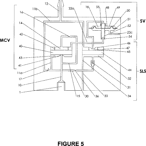
図5は図3に類似したものであり、図4の装置の実際的な実施形態をより詳細に示す。図5の実施形態の構造及び動作は、先の説明から十分に理解されるであろう。次の表は、図5の装置の動作シーケンスをまとめたものであり、各段階における圧力及びバルブの状態を記載している。先と同様、記載のパーセントは、供給圧力に対する比率を示す。
次に、本発明の第2の実施形態を示す図6を参照する。図6の実施形態と先の両実施形態との相違点は、検出遅延ボリューム32が、その固有の検出遅延バルブではなく検出バルブ21を制御すべく作用することにある。これは制御管路37で表される。検出遅延バルブ21の動作は、2つのボリューム、すなわち検出ボリューム18及び検出遅延ボリューム32内の圧力レベルの制御下にある。図6では、様々な制御ボリュームの排気及び充填ならびにバルブの動作は先に述べたものと本質的に同じであり、よって相違点のみを論じる。
Reference is now made to FIG. 6 which shows a second embodiment of the present invention. The difference between the embodiment of FIG. 6 and the previous embodiments is that the
検出バルブ21は、先に述べた方法で、検出ボリューム18内の圧力により、制御管路20を介して制御される。制御管路37による制御はこれに優先し、検出遅延ボリューム内の圧力が供給圧力の10%を超えると前記バルブの動作を抑止するように作用する。したがって、出力管路11aがユーザへ供給される気体パルスの開始時に圧力を供給すべく加圧された状態になると、検出遅延ボリュームは管路30及び一方向バルブ31を介して加圧される。検出遅延ボリューム32の圧力が供給圧力の10%を超えた状態になると、制御管路37を介して検出バルブ21の動作が抑止され、この状態が、先に述べたようにして、予め定めた時間が終わるまで、これに続く呼気の間も続く。したがって、先の場合と同様に、バルブ21は閉じたままであり、こうして主制御ボリューム14の通気管路22を介する通気が防止される。
The
制御管路37で示す制御をかける方法は様々であり、次に、より詳細な空気圧回路図である図7及び図8を参照し、そのうち2つについて説明する。
There are various methods for applying the control indicated by the
まず、図7を参照すると、遅延検出ダイアフラム44がピストン60に置き換えられ、該ピストンには円筒の外部で検出バルブの検出ボリューム18内へ延設されるシャフト61が取り付けられているという主たる相違点を除き、図3に類似していることが分かるであろう。実際には、ピストン60はダイアフラム44に多少類似したダイアフラムによって構成されることが理解されるであろう。
First, referring to FIG. 7, the main difference is that the
ピストン60は、シャフト61の下端が検出ダイアフラム48から離れていて、その正常な動作を妨げないような方法で、ばね46により偏倚される。しかしながら、検出遅延ボリューム32内の圧力に応じて、ピストン60及びシャフト61は下方へ移動し、シャフト61の下端がダイアフラム48に係合して、患者による吸入の結果としての出力管路11b内の陰圧に応じた該ダイアフラムの上方移動を防止する。したがって、検出バルブのジェット54は閉じたままとなり、主ボリューム14の通気が防止される。
The
この状況は、検出遅延ボリューム32が通気管路33及び制限器34を介して通気され、ボリューム32内の圧力が供給圧力の10%未満になるまで続く。この時点で、シャフト61の下端は、検出ダイアフラム48が正常に動作できる位置まで上昇している。
This situation continues until the
次に、図8を参照すると、これは、ピストン60のシャフト61がバルブステム52に作用することを除けば、図7と極めてよく似ていることが分かるであろう。
Referring now to FIG. 8, it will be seen that this is very similar to FIG. 7 except that the shaft 61 of the
シャフト61の端は、図示された位置ではバルブステム52から離れ、よって、検出バルブは正常に動作する。この状態では、ユーザの吸入に起因してダイアフラム48が持ち上がり、通気管路22a内の圧力によってバルブステム52が上昇する。したがって、通気管路22a内の気体はバルブステム側面の周囲からチャンバ51へ逃げ、通気管路22cを介して大気へ通気される。しかしながら、検出遅延ボリューム32内の圧力が供給圧力の10%を超えて上昇すれば、ピストン60及びシャフト61は右方向へ移動し、シャフト61の右端をバルブステム52に係合させてその移動を防止する。これにより、バルブステム52はジェット54をシールする位置にロックされ、よって、主制御ボリューム14の通気管路22aを介する通気が防止される。この状況は、検出遅延ボリューム32内の圧力が供給圧力の10%を超えたままである限り続き、よって、この間の検出バルブの動作は効果的に抑止される。
The end of the shaft 61 is separated from the
図7及び図8の各実施形態の動作は本質的に極めて類似しており、個々の動作シーケンスならびに各段階における圧力及びバルブの状態を記した次の表にまとめることができる。先と同様に、記載のパーセントは、供給圧力に対する比率を示す。次表において、ピストン60が上と記載されている場合、これは、シャフト61が検出バルブ(SV)の動作に影響しない位置にあることを意味し、ピストン60が下と記載されていれば、これは、シャフト61が検出バルブの動作を妨げる位置にあることを意味する。
Claims (23)
Applications Claiming Priority (9)
| Application Number | Priority Date | Filing Date | Title |
|---|---|---|---|
| GB0504223A GB0504223D0 (en) | 2005-03-02 | 2005-03-02 | An oxygen conserving device |
| GB0504223.9 | 2005-03-02 | ||
| GB0519620A GB0519620D0 (en) | 2005-09-27 | 2005-09-27 | An oxygen conserving device |
| GB0519620.9 | 2005-09-27 | ||
| GB0519730A GB0519730D0 (en) | 2005-09-28 | 2005-09-28 | An oxygen conserving device |
| GB0519729.8 | 2005-09-28 | ||
| GB0519729A GB0519729D0 (en) | 2005-09-28 | 2005-09-28 | An oxygen conserving device |
| GB0519730.6 | 2005-09-28 | ||
| PCT/GB2006/050043 WO2006092635A1 (en) | 2005-03-02 | 2006-03-02 | Conserving device for breathable gas |
Publications (2)
| Publication Number | Publication Date |
|---|---|
| JP2008531164A JP2008531164A (en) | 2008-08-14 |
| JP4992724B2 true JP4992724B2 (en) | 2012-08-08 |
Family
ID=36190648
Family Applications (1)
| Application Number | Title | Priority Date | Filing Date |
|---|---|---|---|
| JP2007557599A Active JP4992724B2 (en) | 2005-03-02 | 2006-03-02 | Breathing gas saving device |
Country Status (6)
| Country | Link |
|---|---|
| US (1) | US8276584B2 (en) |
| EP (1) | EP1863555B1 (en) |
| JP (1) | JP4992724B2 (en) |
| AT (1) | ATE449625T1 (en) |
| DE (1) | DE602006010677D1 (en) |
| WO (1) | WO2006092635A1 (en) |
Families Citing this family (50)
| Publication number | Priority date | Publication date | Assignee | Title |
|---|---|---|---|---|
| US7588033B2 (en) | 2003-06-18 | 2009-09-15 | Breathe Technologies, Inc. | Methods, systems and devices for improving ventilation in a lung area |
| CA2536090C (en) | 2003-08-18 | 2014-07-22 | Anthony D. Wondka | Method and device for non-invasive ventilation with nasal interface |
| JP2009508645A (en) | 2005-09-20 | 2009-03-05 | ルッツ フレイテッグ, | System, method and apparatus for assisting patient breathing |
| US8668767B2 (en) | 2007-04-20 | 2014-03-11 | Invacare Corporation | Product gas concentrator and method associated therewith |
| US7909033B2 (en) | 2006-05-03 | 2011-03-22 | Comedica Incorporated | Breathing treatment apparatus |
| CA2652544A1 (en) | 2006-05-18 | 2007-12-13 | Breathe Technologies, Inc. | Tracheostoma spacer, tracheotomy method, and device for inserting a tracheostoma spacer |
| EP2068992B1 (en) | 2006-08-03 | 2016-10-05 | Breathe Technologies, Inc. | Devices for minimally invasive respiratory support |
| US8307828B2 (en) | 2006-08-24 | 2012-11-13 | Inovo, Inc. | Pneumatic single-lumen medical gas conserver |
| US8051854B2 (en) | 2006-09-15 | 2011-11-08 | Comedica Incorporated | Continuous high-frequency oscillation breathing treatment apparatus |
| US9186476B2 (en) | 2007-01-31 | 2015-11-17 | Ric Investments, Llc | System and method for oxygen therapy |
| WO2008144589A1 (en) | 2007-05-18 | 2008-11-27 | Breathe Technologies, Inc. | Methods and devices for sensing respiration and providing ventilation therapy |
| US9050434B2 (en) | 2007-05-18 | 2015-06-09 | Comedica Incorporated | Lung therapy device |
| EP2203206A4 (en) | 2007-09-26 | 2017-12-06 | Breathe Technologies, Inc. | Methods and devices for treating sleep apnea |
| EP2200686A4 (en) | 2007-09-26 | 2017-11-01 | Breathe Technologies, Inc. | Methods and devices for providing inspiratory and expiratory flow relief during ventilation therapy |
| EP2274036A4 (en) | 2008-04-18 | 2014-08-13 | Breathe Technologies Inc | Methods and devices for sensing respiration and controlling ventilator functions |
| US8776793B2 (en) | 2008-04-18 | 2014-07-15 | Breathe Technologies, Inc. | Methods and devices for sensing respiration and controlling ventilator functions |
| US8251876B2 (en) | 2008-04-22 | 2012-08-28 | Hill-Rom Services, Inc. | Breathing exercise apparatus |
| US8677999B2 (en) | 2008-08-22 | 2014-03-25 | Breathe Technologies, Inc. | Methods and devices for providing mechanical ventilation with an open airway interface |
| US10252020B2 (en) | 2008-10-01 | 2019-04-09 | Breathe Technologies, Inc. | Ventilator with biofeedback monitoring and control for improving patient activity and health |
| US8082312B2 (en) | 2008-12-12 | 2011-12-20 | Event Medical, Inc. | System and method for communicating over a network with a medical device |
| US9132250B2 (en) | 2009-09-03 | 2015-09-15 | Breathe Technologies, Inc. | Methods, systems and devices for non-invasive ventilation including a non-sealing ventilation interface with an entrainment port and/or pressure feature |
| US9180270B2 (en) | 2009-04-02 | 2015-11-10 | Breathe Technologies, Inc. | Methods, systems and devices for non-invasive open ventilation with gas delivery nozzles within an outer tube |
| US9962512B2 (en) | 2009-04-02 | 2018-05-08 | Breathe Technologies, Inc. | Methods, systems and devices for non-invasive ventilation including a non-sealing ventilation interface with a free space nozzle feature |
| CN102762250B (en) | 2009-09-03 | 2017-09-26 | 呼吸科技公司 | Mthods, systems and devices for including the invasive ventilation with entrainment port and/or the non-tight vented interface of pressure characteristic |
| US9151425B2 (en) | 2009-11-02 | 2015-10-06 | Comedica Incorporated | Multiple conduit connector apparatus and method |
| US8171094B2 (en) | 2010-01-19 | 2012-05-01 | Event Medical, Inc. | System and method for communicating over a network with a medical device |
| WO2012024342A1 (en) | 2010-08-16 | 2012-02-23 | Breathe Technologies, Inc. | Methods, systems and devices using lox to provide ventilatory support |
| EP2621575B1 (en) | 2010-09-30 | 2018-04-04 | Breathe Technologies, Inc. | Devices for humidifying a respiratory tract |
| EP2627390B1 (en) * | 2010-10-14 | 2018-12-05 | Ventific Holdings Pty Ltd | A respiratory valve apparatus |
| US11624443B2 (en) | 2011-05-10 | 2023-04-11 | Oxypoint Nv | Valve for controlling gas flow |
| BE1020243A5 (en) * | 2011-05-10 | 2013-07-02 | Oxypoint Bvba | GAS VALVE FOR CHECKING GAS FLOW. |
| US9180271B2 (en) | 2012-03-05 | 2015-11-10 | Hill-Rom Services Pte. Ltd. | Respiratory therapy device having standard and oscillatory PEP with nebulizer |
| CN104271218B (en) | 2012-03-09 | 2017-03-01 | 英瓦卡尔公司 | The system and method that concentrated gas are come by absorption |
| US9795752B2 (en) | 2012-12-03 | 2017-10-24 | Mhs Care-Innovation, Llc | Combination respiratory therapy device, system, and method |
| US12080401B2 (en) | 2012-12-03 | 2024-09-03 | Metrohealth Ventures Llc | Combination respiratory therapy device, system and method |
| US20150175104A1 (en) * | 2013-12-20 | 2015-06-25 | B/E Aerospace, Inc. | Energy harvesting for the electronic regulation of oxygen flow |
| EP4186548A1 (en) | 2015-04-02 | 2023-05-31 | Hill-Rom Services PTE. LTD. | Mask leakage detection for a respiratory device |
| GB2538509A (en) * | 2015-05-18 | 2016-11-23 | C2M Design Ocd Ltd | An oxygen system for parachuting |
| BR112018004314B1 (en) | 2015-09-04 | 2023-01-31 | L'air Liquide, Societe Anonyme Pour L'etude Et L'exploitation Des Procedes Georges Claude | GAS DEMAND DEVICE |
| US10982773B2 (en) | 2016-10-02 | 2021-04-20 | Peter Wojtach | Gas concentrator apparatus and method of use thereof |
| WO2018151826A1 (en) * | 2017-02-16 | 2018-08-23 | L'air Liquide Societe Anonyme Pour L'etude Et L'exploitation Des Procedes Georges Claude | Method and system for gas delivery including gas conserver |
| US10792449B2 (en) | 2017-10-03 | 2020-10-06 | Breathe Technologies, Inc. | Patient interface with integrated jet pump |
| US12070554B2 (en) | 2019-11-11 | 2024-08-27 | Hill-Rom Services Pte. Ltd. | Pneumatic connector apparatus and method |
| US12329997B2 (en) * | 2020-03-26 | 2025-06-17 | The Boeing Company | Apparatus, system, and method for pressure altitude-compensating breath-controlled oxygen release |
| WO2022015906A1 (en) | 2020-07-16 | 2022-01-20 | Invacare Corporation | System and method for concentrating gas |
| EP4182054A4 (en) | 2020-07-16 | 2024-11-06 | Ventec Life Systems, Inc. | System and method for concentrating gas |
| EP4181993A4 (en) | 2020-07-16 | 2024-08-07 | Ventec Life Systems, Inc. | GAS CONCENTRATION SYSTEM AND METHOD |
| AU2021307935A1 (en) | 2020-07-16 | 2023-03-16 | Ventec Life Systems, Inc. | System and method for concentrating gas |
| US12347555B2 (en) | 2021-07-15 | 2025-07-01 | Ventec Life Systems, Inc. | System and method for medical device communication |
| GB2635757A (en) * | 2023-11-25 | 2025-05-28 | C2M Design Ocd Ltd | A system for the delivery of supplemental oxygen |
Family Cites Families (18)
| Publication number | Priority date | Publication date | Assignee | Title |
|---|---|---|---|---|
| US4054133A (en) * | 1976-03-29 | 1977-10-18 | The Bendix Corporation | Control for a demand cannula |
| US4461293A (en) * | 1982-12-03 | 1984-07-24 | Kircaldie, Randall, And Mcnab | Respirating gas supply method and apparatus therefor |
| US4699351A (en) * | 1984-07-11 | 1987-10-13 | Target Rock Corporation | Pressure responsive, pilot actuated, modulating valve |
| US4932402A (en) * | 1986-04-11 | 1990-06-12 | Puritan-Bennett Corporation | Inspiration oxygen saver |
| US4706664A (en) * | 1986-04-11 | 1987-11-17 | Puritan-Bennett Corporation | Inspiration oxygen saver |
| US5099836A (en) * | 1987-10-05 | 1992-03-31 | Hudson Respiratory Care Inc. | Intermittent oxygen delivery system and cannula |
| US5666945A (en) | 1995-06-07 | 1997-09-16 | Salter Labs | Pneumatically-operated gas demand apparatus |
| US5603315A (en) * | 1995-08-14 | 1997-02-18 | Reliable Engineering | Multiple mode oxygen delivery system |
| GB9723319D0 (en) * | 1997-11-04 | 1998-01-07 | Protector Technologies Bv | Oxygen therapy apparatus |
| WO2000023134A1 (en) | 1998-10-21 | 2000-04-27 | Airsep Corporation | Combined oxygen regulator and conservation device |
| US6237594B1 (en) * | 1999-09-22 | 2001-05-29 | Salter Labs | Pneumatically-operated gas demand apparatus |
| US6378520B1 (en) * | 1999-10-29 | 2002-04-30 | Salter Labs | Variable pressure and flow control for a pneumatically-operated gas demand apparatus |
| US6484721B1 (en) * | 2001-06-27 | 2002-11-26 | Chad Therapeutics, Inc. | Pneumatic oxygen conserving device |
| US7089938B2 (en) | 2001-10-19 | 2006-08-15 | Precision Medical, Inc. | Pneumatic oxygen conserving device |
| US7708016B2 (en) * | 2002-11-12 | 2010-05-04 | Inovo, Inc. | Gas conserving regulator |
| US7591266B2 (en) * | 2003-02-04 | 2009-09-22 | Inovo, Inc. | Hybrid electro-pneumatic conserver for oxygen conserving regulator |
| JP4602643B2 (en) * | 2003-02-28 | 2010-12-22 | 帝人株式会社 | Respiratory gas supply device |
| US7191780B2 (en) * | 2003-09-22 | 2007-03-20 | Comedica Incorporated | Continuous high-frequency oscillation breathing treatment apparatus |
-
2006
- 2006-03-02 JP JP2007557599A patent/JP4992724B2/en active Active
- 2006-03-02 AT AT06727158T patent/ATE449625T1/en not_active IP Right Cessation
- 2006-03-02 WO PCT/GB2006/050043 patent/WO2006092635A1/en not_active Ceased
- 2006-03-02 US US11/817,557 patent/US8276584B2/en active Active
- 2006-03-02 EP EP06727158A patent/EP1863555B1/en active Active
- 2006-03-02 DE DE602006010677T patent/DE602006010677D1/de active Active
Also Published As
| Publication number | Publication date |
|---|---|
| US8276584B2 (en) | 2012-10-02 |
| WO2006092635A1 (en) | 2006-09-08 |
| EP1863555A1 (en) | 2007-12-12 |
| DE602006010677D1 (en) | 2010-01-07 |
| US20080190429A1 (en) | 2008-08-14 |
| JP2008531164A (en) | 2008-08-14 |
| EP1863555B1 (en) | 2009-11-25 |
| ATE449625T1 (en) | 2009-12-15 |
Similar Documents
| Publication | Publication Date | Title |
|---|---|---|
| JP4992724B2 (en) | Breathing gas saving device | |
| US6484721B1 (en) | Pneumatic oxygen conserving device | |
| JP3183527B2 (en) | Flow starter for assisted ventilation | |
| CA2223328C (en) | Pneumatically-operated gas demand apparatus | |
| US6237594B1 (en) | Pneumatically-operated gas demand apparatus | |
| US12434032B2 (en) | Oxygen gas concentrator with outlet accumulator | |
| CN101553284B (en) | Detecting ventilator system anomalies while in a speaking mode | |
| CN102727975B (en) | Breathing gas supply and shared system and method thereof | |
| JP7016319B2 (en) | Portable lightweight ventilator system | |
| CN104363945B (en) | Method and apparatus for assisted respiartion | |
| US20100043796A1 (en) | Systems for reducing exhalation pressure in a mask system | |
| JP2006527635A5 (en) | ||
| US20200268994A1 (en) | Gas delivery device with deformable bag and differential pressure sensors | |
| US20100043790A1 (en) | Nebuliser valve | |
| US20200269007A1 (en) | Automatic gas delivery device | |
| US5443062A (en) | Load activated oxygen delivery system | |
| WO2016057694A1 (en) | Devices, systems, and methods for applying positive end expiratory pressure | |
| AU724524B2 (en) | Pneumatically operated gas demand apparatus |
Legal Events
| Date | Code | Title | Description |
|---|---|---|---|
| A521 | Request for written amendment filed |
Free format text: JAPANESE INTERMEDIATE CODE: A523 Effective date: 20080515 |
|
| A521 | Request for written amendment filed |
Free format text: JAPANESE INTERMEDIATE CODE: A821 Effective date: 20080519 |
|
| A621 | Written request for application examination |
Free format text: JAPANESE INTERMEDIATE CODE: A621 Effective date: 20090223 |
|
| A131 | Notification of reasons for refusal |
Free format text: JAPANESE INTERMEDIATE CODE: A131 Effective date: 20110506 |
|
| A977 | Report on retrieval |
Free format text: JAPANESE INTERMEDIATE CODE: A971007 Effective date: 20110512 |
|
| A601 | Written request for extension of time |
Free format text: JAPANESE INTERMEDIATE CODE: A601 Effective date: 20110804 |
|
| A602 | Written permission of extension of time |
Free format text: JAPANESE INTERMEDIATE CODE: A602 Effective date: 20110811 |
|
| A521 | Request for written amendment filed |
Free format text: JAPANESE INTERMEDIATE CODE: A523 Effective date: 20111005 |
|
| TRDD | Decision of grant or rejection written | ||
| A01 | Written decision to grant a patent or to grant a registration (utility model) |
Free format text: JAPANESE INTERMEDIATE CODE: A01 Effective date: 20120410 |
|
| A01 | Written decision to grant a patent or to grant a registration (utility model) |
Free format text: JAPANESE INTERMEDIATE CODE: A01 |
|
| A61 | First payment of annual fees (during grant procedure) |
Free format text: JAPANESE INTERMEDIATE CODE: A61 Effective date: 20120423 |
|
| FPAY | Renewal fee payment (event date is renewal date of database) |
Free format text: PAYMENT UNTIL: 20150518 Year of fee payment: 3 |
|
| R150 | Certificate of patent or registration of utility model |
Ref document number: 4992724 Country of ref document: JP Free format text: JAPANESE INTERMEDIATE CODE: R150 Free format text: JAPANESE INTERMEDIATE CODE: R150 |
|
| R250 | Receipt of annual fees |
Free format text: JAPANESE INTERMEDIATE CODE: R250 |
|
| R250 | Receipt of annual fees |
Free format text: JAPANESE INTERMEDIATE CODE: R250 |
|
| R250 | Receipt of annual fees |
Free format text: JAPANESE INTERMEDIATE CODE: R250 |
|
| R250 | Receipt of annual fees |
Free format text: JAPANESE INTERMEDIATE CODE: R250 |
|
| R250 | Receipt of annual fees |
Free format text: JAPANESE INTERMEDIATE CODE: R250 |
|
| R250 | Receipt of annual fees |
Free format text: JAPANESE INTERMEDIATE CODE: R250 |
|
| R250 | Receipt of annual fees |
Free format text: JAPANESE INTERMEDIATE CODE: R250 |
|
| R250 | Receipt of annual fees |
Free format text: JAPANESE INTERMEDIATE CODE: R250 |
|
| R250 | Receipt of annual fees |
Free format text: JAPANESE INTERMEDIATE CODE: R250 |
|
| R250 | Receipt of annual fees |
Free format text: JAPANESE INTERMEDIATE CODE: R250 |
|
| R250 | Receipt of annual fees |
Free format text: JAPANESE INTERMEDIATE CODE: R250 |