JP4991409B2 - Sheet feeding apparatus and image forming apparatus - Google Patents
Sheet feeding apparatus and image forming apparatus Download PDFInfo
- Publication number
- JP4991409B2 JP4991409B2 JP2007166354A JP2007166354A JP4991409B2 JP 4991409 B2 JP4991409 B2 JP 4991409B2 JP 2007166354 A JP2007166354 A JP 2007166354A JP 2007166354 A JP2007166354 A JP 2007166354A JP 4991409 B2 JP4991409 B2 JP 4991409B2
- Authority
- JP
- Japan
- Prior art keywords
- sheet
- fan
- air
- sheet feeding
- suction
- Prior art date
- Legal status (The legal status is an assumption and is not a legal conclusion. Google has not performed a legal analysis and makes no representation as to the accuracy of the status listed.)
- Expired - Fee Related
Links
Images


Landscapes
- Controlling Sheets Or Webs (AREA)
- Sheets, Magazines, And Separation Thereof (AREA)
Description
本発明は複数のシートが収納された収納庫からシートを1枚ずつ給送するシート給送装置、若しくはそのシート給送装置を備えた画像形成装置に関するものである。 The present invention relates to a sheet feeding apparatus that feeds sheets one by one from a storage that stores a plurality of sheets, or an image forming apparatus that includes the sheet feeding apparatus.
従来、プリンタ、複写機等の画像形成装置において、シート束を収納した収納庫からシートを1枚ずつ分離して給送するためのシート給送装置が設けられている。このシート給送装置において、収納されているシート束端部にエアを吹き付けてシートを複数枚浮上させ、吸着搬送ベルトに最上位のシートを1枚だけ吸着して搬送する、いわゆるエア給紙方式が提案されている(特許文献1参照。)
このエア給紙方式のシート給送装置は、主に高い生産性と信頼性、多種のシートへの対応が求められる装置に使用されることが多く、例えば、電子写真方式の画像形成装置を用いたPOD(print on demand)のシステムに使用される。
2. Description of the Related Art Conventionally, in an image forming apparatus such as a printer or a copying machine, a sheet feeding device is provided for separating and feeding sheets one by one from a storage that stores a sheet bundle. In this sheet feeding apparatus, a so-called air feeding system in which a plurality of sheets are floated by blowing air to the end of a bundle of stored sheets, and only one uppermost sheet is sucked and transported to the suction transport belt Has been proposed (see Patent Document 1).
This air feeding type sheet feeding apparatus is often used mainly for an apparatus that requires high productivity and reliability, and supports various types of sheets. For example, an electrophotographic image forming apparatus is used. It is used for a POD (print on demand) system.
次に、従来のエア給紙方式のシート給送装置の一例を説明する。 Next, an example of a conventional air feeding type sheet feeding apparatus will be described.
図13に示すように、シートトレイ12にシートSを支持して収納する収納庫11と、シート束の最上位のシートを吸着して搬送する吸着搬送部と、シート束の上部を浮上させるためのエアを吹き付けるエア吹き付け部とを備えている。吸着搬送部は、吸着搬送ベルト21と、吸着ファン36と、吸着シャッタ37と、吸引ダクト51等を備えている。
As shown in FIG. 13, the
吸着搬送ベルト21は、ベルト駆動ローラ41,41に掛け渡されており、シートSを吸着して図中右方向に搬送する。吸着ファン36は、シートを吸着搬送ベルト21に吸着させるための負圧を発生するために設けられており、吸着搬送ベルト21の内側に配置された吸引ダクト51と接続されている。そして、吸着ファン36が動作して吸引ダクト51内に負圧生じさせ、吸着搬送ベルト21に形成されている図示しない吸引穴を介してエアを吸引することにより吸着搬送ベルト21にシートを吸着させる。
The
吸着シャッタ37は、吸着搬送ベルト21のシートの吸着動作をするために吸着ファン36と吸引ダクト51の間に配置されている。図13では吸着シャッタ37により吸着ファン36と吸引ダクト51とが遮断されて吸着搬送ベルト21によるシートの吸着がされない状態を示している。そして、吸着シャッタ37が矢印に示す方向に90°回転することにより吸着ファン36と吸引ダクト51とが連通されてシートを吸着可能な状態となる。
The
また、エア吹き付け部は、収納されているシート束の上部に側方からエアを吹き付けるための捌きノズル33と分離ノズル34とを備え、各ノズル33,34には分離ダクト32を介して分離ファン31からエアが送られるように接続されている。
In addition, the air blowing unit includes a
分離ファン31により図中矢印C方向に吸い込まれたエアは捌きノズル33により、収納庫11の収納されているシート束の上部に向けてD方向に吹き付けられ、シート束の上部のうち数枚を浮上させる。また分離ノズル34によりシート束の上部に向けてE方向にも吹き付けられ、最上位のシートを分離して吸着搬送ベルト21に吸着させる。
The air sucked in the direction of arrow C in the figure by the
シートSを吸着搬送ベルト21に確実に1枚ずつ吸着させるためには、最上位のシートの高さを吸着に適した高さに制御する必要がある。そこで、図14に示すように、支持軸53に回転自在に支持されるシート検知センサフラグ52と、シート検知センサ54を備える紙面検知機構49が設けられている。このシート検知センサ54の検知に基づいて、図示しない制御手段がシートトレイ12の昇降を制御し、最上位のシートの高さを吸着に適した高さに位置させている。
In order to securely adsorb the sheets S to the
このシート給送装置において、シート給送動作を行う際は、エアは捌きノズル33からエアを吹き付けてシートを浮上させ、紙面検知機構49の検知に基づいてシートトレイ12を昇降させて最上位のシートSaを吸着に適した高さに移動させる。そして、吸着ファン36を動作させてシートSaを吸着搬送ベルト21に吸着させ、吸着搬送ベルト21を回転させることで下流側の引き抜きローラ対にシートSaを引き渡す。シートSaが吸着搬送ベルト21を通過した後に吸着搬送ベルト21を停止させて、紙面検知機構49を用いて次のシートSbが吸着に適した高さになるようにシートトレイ12の昇降を制御する。
In this sheet feeding apparatus, when performing the sheet feeding operation, air blows air from the
このようなシート給送装置では最上位のシートの位置しか検知ができないため、その下で浮上しているシートの浮上状態、すなわち捌かれているシートの状態がどのようになっているかを判断することができない。 In such a sheet feeding apparatus, only the position of the uppermost sheet can be detected, and therefore, the floating state of the sheet floating below it, that is, the state of the sheet being rolled is determined. I can't.
例えば、図15の(1),(2)では、最上シートSaの高さは適正な位置であるがそれ以下の浮上されているシートが捌かれていない捌き不良状態を示しており、図15の(3)では、浮上しているシートが最適に捌かれている状態を示している。このような浮上状態が生じる原因としては、使用される多種のシートの中に、温度・湿度の環境変動によりシート束の状態で反りを発生するものや表面が密着しやすいコーティングを施されたものなどがあるためである。 For example, FIGS. 15 (1) and 15 (2) show a state where the uppermost sheet Sa is in an appropriate position, but the floating sheet below it is not rolled up, and is in a defective state. (3) shows a state in which the floating sheet is optimally rolled. The reason why such a floating state occurs is that various types of used sheets are warped in the state of a bundle of sheets due to environmental fluctuations in temperature and humidity, or coated with a surface that easily adheres to the surface. Because there are.
図15の(1)に示すシートの浮上状態では、最上位のシートSaと次のシートSbの密着力が吸着搬送ベルト21へのシートの吸着力よりも大きくなり、最上位のシートSaの吸着搬送ベルト21へ吸着が失敗してジャム(紙詰り)を発生するおそれがある。図15の(2)に示す状態では、最上位のシートSaのみが捌かれている状態を示しているが、この場合には、最上位のシートSaを給送後、次のシートSb以下の下位シートを捌く時間が長くかかってしまう。この場合、仮にシートが吸着搬送ベルト21へ吸着したとしても吸着に要する時間が長くなるため、高い生産性を求められる画像形成装置においては容認できないタイムロスとなる。
In the sheet floating state shown in FIG. 15A, the adhesion force between the uppermost sheet Sa and the next sheet Sb is larger than the adsorption force of the sheet to the
そこで、最上位のシートより下のシートの捌き状態を検出する方法が考えられる。例えば、収納されているシート束の側面よりCCDなどの撮像素子でシート束の浮上状態を撮像し、撮像した画像データの画像処理を行うことによりシートの情報を得るようにしたものがある(特許文献2参照)。 In view of this, a method of detecting the rolling state of the sheet below the uppermost sheet is conceivable. For example, a sheet bundle is captured from the side of the stored sheet bundle with an image sensor such as a CCD, and sheet information is obtained by performing image processing on the captured image data (patent) Reference 2).
これは、収納されたシート束の側方からエアノズルでエアを吹き付け、対向する位置に配置されているCCDセンサで浮上したシートの状態を撮影するものであり、撮影した画像データに基づいてシートの状態を検出することが可能である。そして、このシートの浮上状態の検出に基づいてエアの吹き付け量(風量)を変更することにより、図15の(3)に示すように最適にシートを捌くことができる。
しかしながら、シートの浮上状態を検出するためにCCDなどの撮像素子でシート束の浮上状態を撮像するものでは、装置構成が複雑となり装置の大型化及び装置コストの増大を招き、画像処理等のソフト等も必要となるためさらにコストが増大するという課題がある。 However, in order to detect the floating state of the sheet with an image pickup device such as a CCD, the image of the floating state of the sheet bundle is complicated, which increases the size of the apparatus and increases the cost of the apparatus. Etc. are also required, and there is a problem that the cost further increases.
本発明は、以上の問題に鑑みてなされたものであり、エア給紙方式のシート給送装置において、装置の大型化やコストの増大を招くことなく、シートの給送に対して高い生産性と信頼性、多種のシートへの対応力を向上させることを目的とする。 The present invention has been made in view of the above problems, and in a sheet feeding apparatus of an air feeding method, high productivity with respect to sheet feeding without causing an increase in size and cost of the apparatus. The purpose is to improve the reliability and compatibility with various types of seats.
本発明は、シート束を支持するシートトレイと、前記シートトレイに支持されているシート束の最上位のシートを1枚ずつ給送するシート給送手段と、エアを吹き付けて前記シートトレイに支持されているシート束を捌くエア吹き付け手段と、前記エア吹き付け手段に設けられ、回転が制御可能な捌きファンと、を有し、前記捌きファンは、予め設定されている目標回転数となるように回転が制御され、前記捌きファンの回転数による捌き不良を判断するための閾値を備え、シート束を捌いているときの前記捌きファンの回転数と前記閾値とを比較判断して捌き不良と判断した場合には、前記捌きファンの回転数を変更することを特徴とする。 The present invention provides a sheet tray that supports a sheet bundle, a sheet feeding unit that feeds the uppermost sheet of the sheet bundle supported by the sheet tray one by one, and supports the sheet tray by blowing air. and air blowing means loosened the sheet bundle being provided in the air blowing unit, rotary has a loosening fan controllable, wherein the loosening fan, as a target speed that is set in advance Rotation is controlled, and a threshold value is provided for determining a winding failure due to the rotation speed of the winding fan, and the rotation speed of the winding fan when the sheet bundle is being rolled is compared with the threshold value to determine a winding failure. In such a case, the number of rotations of the fan is changed .
また、本発明は、シート束を支持するシートトレイと、前記シートトレイに支持されているシート束の最上位のシートを1枚ずつ給送するシート給送手段と、エアを吹き付けて前記シート束を捌くエア吹き付け手段と、を有し、前記エア吹き付け手段は、エアを前記シート束に吹き付けるための捌きエア吹き付け部と、前記捌きエア吹き付け部にエアを供給するために設けられ、回転が制御可能な捌きファンと、前記捌きエア吹き付け部と前記捌きファンとを接続する捌きダクトと、を有し、前記捌きダクトの内圧に応じて前記捌きファンの回転数を変更することを特徴とする。 The present invention also provides a sheet tray that supports the sheet bundle, a sheet feeding unit that feeds the uppermost sheet of the sheet bundle supported by the sheet tray one by one, and the sheet bundle by blowing air. Air blowing means for blowing air, and the air blowing means is provided for blowing air to the sheet bundle and for supplying air to the blowing air blowing part, and the rotation is controlled. It has a possible burning fan, and a burning duct that connects the burning air blowing part and the burning fan, and the number of rotations of the burning fan is changed according to the internal pressure of the burning duct.
本発明によれば、ファンの回転数の変化または捌きダクトの内圧の変化からシートの捌き状態を判断して、エアの吹き付けをシートが最適な捌き状態となるように変更することができる。これにより、多種類のシートに対して確実に捌くことができ、かつ、生産性を落とすことなくシートの給送が可能となる。そして、CCDなどの撮像素子等の高価なセンサが不要となるため、安価な構成で装置を実現することができる。 According to the present invention, it is possible to determine the sheet blowing state from the change in the rotation speed of the fan or the change in the internal pressure of the burning duct, and to change the air blowing so that the sheet is in the optimum winding state. As a result, it is possible to reliably roll over various types of sheets, and it is possible to feed sheets without reducing productivity. In addition, since an expensive sensor such as an image pickup device such as a CCD is not required, the apparatus can be realized with an inexpensive configuration.
以下、本発明を実施するための形態について、図面を用いて詳細に説明する。図2は本発明を採用したシート給送装置を備えた画像形成装置の概略断面図である。まず、図2を用いて画像形成装置の全体を説明する。 Hereinafter, embodiments for carrying out the present invention will be described in detail with reference to the drawings. FIG. 2 is a schematic sectional view of an image forming apparatus provided with a sheet feeding apparatus employing the present invention. First, the entire image forming apparatus will be described with reference to FIG.
画像形成装置本体の上部には、画像読取部130が配置されている。画像読取部130には、原稿を自動的に画像読取部130に給送するための自動原稿給送装置が接続されている。そして、この自動原稿給送装置の原稿搬送部120により原稿が画像読取部130の読取位置まで自動的に送られて画像情報が読み取られる。
An
読み取られた画像情報は不図示のコントローラにより処理され、処理結果に基づいた信号によって、レーザスキャナユニット111からレーザ光が発せられ、感光体ドラム112上に静電潜像が形成される。
The read image information is processed by a controller (not shown), and a laser beam is emitted from the laser scanner unit 111 based on a signal based on the processing result, and an electrostatic latent image is formed on the
画像形成装置の下側にはシート給送装置が配置されており、シート給送装置は、装置本体から引き出し可能な収納庫11と、後述する吸着搬送ベルト21等を備えたエア給紙方式のシート給送機構とを備えている。収納庫11に収納された記録紙やOHT等のシートはシート給送機構により画像形成部に給送される。
A sheet feeding device is disposed on the lower side of the image forming apparatus. The sheet feeding device is an air feeding type that includes a
画像形成部では、感光体ドラム上の静電潜像が現像器113により現像され、現像された感光ドラム上のトナー画像が、レジスト部117において同期が取られたシートに転写部118において転写される。さらにトナー像が転写されたシートは定着ローラ対114に導かれて、加熱、加圧処理されて定着されて画像形成装置本体から排出される。
In the image forming unit, the electrostatic latent image on the photosensitive drum is developed by the developing
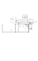
図1に本実施の形態のシート給送装置の主断面を示す。 FIG. 1 shows a main cross section of the sheet feeding apparatus of the present embodiment.
図1において、収納庫11は、複数のシートを支持して昇降可能なシートトレイ12と、シートの給送方向上流側(後側)を規制する後端規制板13と、シート搬送方向と直角をなす方向(シート幅方向)を規制する側端規制板14とが設けられている。また、収納庫11を画像形成装置本体(以下、装置本体という)から手前側(紙面と垂直方向)に引き出すためのスライドレール15が配置されている。収納庫11が装置本体から引き出されたときにシートトレイ12が所定の位置まで下降してシートの補充や交換等を行うことができる。
In FIG. 1, the
シートトレイ12は、ステッピングモータまたはDCサーボモータ等の駆動源により昇降される。また、後端規制板13及び側端規制板14は、収納されるシートのサイズによって位置を任意に変えられるように構成されている。
The
収納庫11の上方にはシートを1枚ずつ分離して給送するためのエア給紙方式のシート給送機構(以下、エア給紙機構という)が配置されている。このエア給紙機構は、従来と同様に、シートを吸着搬送する吸着搬送部と、収納されているシートの上部を浮上させるとともに1枚ずつ分離するためのエア吹き付け部とを備えている。吸着搬送部は、ベルト駆動ローラ41に掛け渡されて、シートを吸着して図中右方向に搬送する吸着搬送ベルト21とを備えている。さらに、シートを吸着搬送ベルト21に吸着させるための負圧を発生する吸着ファン36と、吸着搬送ベルト21の内側に配置され吸着搬送ベルト21に形成されている吸引穴を介してエアを吸引するための吸引ダクト51とを備えている。また、吸着ファン36と吸引ダクト51との間に配置され、吸着搬送ベルト21の吸着動作をON/OFFする吸着シャッタ37等を備えている。
An air feeding type sheet feeding mechanism (hereinafter referred to as an air feeding mechanism) for separating and feeding sheets one by one is disposed above the
また、エア吹き付け部には、収納されているシートの上部にエアを吹き付けるための捌きエア吹き付け部としての捌きノズル33と分離ノズル34とを備え、各ノズルにはそれぞれ捌きファン30と分離ファン31からエアが供給されるように構成されている。捌きファン30と分離ファン31はそれぞれDCファン(シロッコファン)である。
Further, the air blowing section includes a blowing
なお、このエア給紙機構には、図示はしないが、従来と同じ紙面検知機構が設けられており、この紙面検知機構が最上位のシートを検知して、それに基づいてシートトレイ12、吸着搬送ベルト21、エア吹き付け部の動作が制御される。
Although not shown, this air feeding mechanism is provided with the same paper surface detection mechanism as the conventional one. This paper surface detection mechanism detects the uppermost sheet, and based on this, the
ここで、本シート給送装置で使用する捌きファン30は、後述するCPUにより回転が制御可能で、かつ回転信号(回転数)を出力できるタイプのものである。例えば24VでPWM(pulse width modulation)制御100%で駆動すると、回転信号として200Hzのパルス信号を出力する。このように、ファンの種類によって出力の大きさは異なるが、捌きファン30の回転数の出力信号を得ることができるものを使用している。 Here, the rolling fan 30 used in the sheet feeding apparatus is of a type that can be controlled in rotation by a CPU, which will be described later, and that can output a rotation signal (number of rotations). For example, when driven with 100% PWM (pulse width modulation) control at 24 V, a pulse signal of 200 Hz is output as a rotation signal. Thus, although the magnitude | size of an output changes with kinds of fan, what can obtain the output signal of the rotation speed of the fan 30 is used.
また、従来の装置と異なり、捌きノズル33から吹き出すエアの供給源として、捌きファン30を、分離ノズル34にエアを供給する分離ファン31とは別に備えている。さらに、捌きファン30と捌きノズル33を接続するための捌きダクト35と、分離ファン31と分離ノズル34を接続するための分離ダクト32をそれぞれ別々に設けている。さらに捌きノズル33のエア吹き出し口はシートの端部に接するように配置されている。これは本実施の形態では捌き不良状態を判断するために、捌きノズル33から吹き出すエアの圧力すなわち捌きダクト35の内圧が、シートの捌き状態により変化することを用いており、この変化を確実に捉えるためである。この捌き不良状態の判断の方法に関しては後で詳述する。
Further, unlike the conventional apparatus, as a supply source of air blown from the firing
捌きファン30により図中矢印C方向に吸い込まれたエアは捌きノズル33によりD方向に吹き付けられ、収納庫11のシートトレイ12上に支持されているシートの上部のうち数枚を浮上させる。また分離ファン31により矢印E方向に吸い込まれたエアは分離ノズル34によりF方向に吹き付けられ、最上位のシートを1枚に分離して吸着搬送ベルト21に吸着させる。
The air sucked in the direction of arrow C in the figure by the blowing fan 30 is blown in the D direction by the blowing
ここで、捌きファン30は、ユーザーにより入力されたシートの種類(コート・非コート、坪量、サイズ等の少なくとも1つ)、画像形成装置の設置環境(温度・湿度)に応じて最適な捌き状態となるようにCPUにより制御される。なお、設置環境(温度・湿度)は、画像形成装置本体内に設けられた環境センサ(図示せず)により検知される。 Here, the fan 30 is optimally blown according to the sheet type (at least one of coated / uncoated, basis weight, size, etc.) input by the user and the installation environment (temperature / humidity) of the image forming apparatus. It is controlled by the CPU to be in a state. The installation environment (temperature / humidity) is detected by an environmental sensor (not shown) provided in the image forming apparatus main body.
本シート給送装置においては、CPUがシートの種類や画像形成装置の設置環境等の条件に応じた捌きファン30を制御するための目標回転数となるPWM値のテーブルを保持している。このPWM値は、不図示のユーザー操作パネルで収納庫11にセットしたシートの種類を選択すると自動的にテーブルから選ばれて設定される。この目標回転数となるPWM値は、シートの坪量やサイズが大きくなるに従い、エアの風量または風圧を高く、すなわちPWM値を大きくし、またコート紙を高湿環境で給送する場合のようにシート間の吸着が発生するようなときにもPWM値を大きくしている。図7に本実施の形態のシート給送装置におけるPWM値のテーブルの一例を示す。そして、シートの種類や画像形成装置の設置環境等の条件に応じて設定されるPWM値を目標として捌きファン30はPWM制御が行われる。
In the sheet feeding apparatus, a CPU holds a table of PWM values that are target rotation speeds for controlling the fan 30 according to conditions such as the type of sheet and the installation environment of the image forming apparatus. This PWM value is automatically selected from the table and set when the type of sheet set in the
図11は、画像形成装置に設けられている制御ブロック図を示す。 FIG. 11 is a control block diagram provided in the image forming apparatus.
画像形成制御部には、シート給送装置を制御するための制御部(CPU)が接続されている。CPUは、ドライバを介してシートトレイ12を昇降するトレイ昇降モータ、吸着搬送ベルト21を駆動する吸着搬送ベルトモータ、引き抜きローラ対42を駆動する引抜きローラモータの駆動を制御している。さらに、CPUは、吸着ファン36、分離ファン31、捌きファン30のそれぞれの回転を制御している。また、シート検知センサ54,55からの検知信号及び捌きファン30からの上記出力信号が信号処理部を介して入力される。
A control unit (CPU) for controlling the sheet feeding apparatus is connected to the image formation control unit. The CPU controls driving of a tray lifting / lowering motor that lifts and lowers the
次に、上述した捌き不良状態の判断の方法に関して詳細に説明する。 Next, a detailed description will be given of the above-described method for determining the state of failure.
給送信号を検知すると捌きファン30は、シートの種類や環境に基づいて設定された目標回転数で回転させるためのPWM値に従い回転を始める。一定時間経過後、シートが正常に捌かれ浮上した場合には、図15の(3)に示すように捌きノズル33から吹き出されたエアがシートの隙間を抜け、妨げられることなく流れる。その際、捌きダクト35の内圧は捌きノズル33の吹き出し口の前にシートが無いときの内圧に近づく。ところが図15の(1)、(2)に示したように捌き不良状態が発生すると、捌きノズル33から吹き出すエアの流れがシートにより妨げられて捌きダクト35の内圧が上昇する。
When the feeding signal is detected, the rolling fan 30 starts to rotate in accordance with a PWM value for rotating at a target rotational speed set based on the type and environment of the sheet. When the sheet is normally rolled and floated after a certain period of time, as shown in FIG. 15 (3), the air blown from the blowing
ここで、捌きファン30は設定された一定のPWM値で回転しているため、捌きダクト35の内圧が高まるということは、すなわち捌きファン30に加わる負荷が大きくなることである。捌きファン30に加わる負荷が大きくなると、DCファンの特性により、シート無しで想定されている回転信号よりも高い値を出力する。 Here, since the burning fan 30 rotates at a set constant PWM value, the increase in the internal pressure of the burning duct 35 means that the load applied to the burning fan 30 increases. When the load applied to the rolling fan 30 increases, a value higher than the rotation signal assumed without a seat is output due to the characteristics of the DC fan.
この理由を図8に基づいて説明する。なお、図8は、ファンの静圧Pと仕事量Qとの関係を示すグラフ(上段)と、一般的なDCモータにおける回転数N及び電流Iと負荷トルクTとの関係を示すグラフ(下段)とを合わせて記載したものである。 The reason for this will be described with reference to FIG. FIG. 8 is a graph showing the relationship between the static pressure P of the fan and the work amount Q (upper stage), and a graph showing the relationship between the rotational speed N and current I and the load torque T in a general DC motor (lower stage). ).
本実施の形態では、シロッコファン(DCファン)を捌きファン30として用いている。このシロッコファンは、静圧Pがゼロ(ファンの吹き出し口の前に何もない状態)ではエアを最も送り出せる状態であるため最も回転負荷トルクを必要とし、また、最も仕事をしている状態である(図8におけるA点)。そして、シロッコファンの吹き出し口を徐々に塞ぐと、静圧負荷が増加し風量が減少する。風量が減少するということは、仕事量も減少し、負荷トルクも減少することになる(図8の矢印(2)の方向への変位)。 In the present embodiment, a sirocco fan (DC fan) is used as the fan 30. This sirocco fan requires the most rotational load torque and has the most work when the static pressure P is zero (the state where there is nothing in front of the fan outlet) because it is the state where air can be sent out most. (Point A in FIG. 8). When the sirocco fan outlet is gradually closed, the static pressure load increases and the air volume decreases. When the air volume decreases, the work volume also decreases, and the load torque also decreases (displacement in the direction of arrow (2) in FIG. 8).
ここで、一般的なDCモータでは、負荷トルク(T)と電流(I)とは正比例の関係となっており、シロッコファンにおいても同様の関係となっている。そのため、シロッコファンにおいて回転負荷トルクが減少すると電流も同様に減少する(図8における矢印(3)の方向への変位)。また、DCモータでは、負荷トルク(T)と回転数(N)とは正比例の関係(傾きは負)であるため、シロッコファンにおいても、回転負荷トルクが減少すると回転数は逆に増加する(図8の矢印(4)の方向への変位)。 Here, in a general DC motor, the load torque (T) and the current (I) are directly proportional to each other, and the sirocco fan has a similar relationship. Therefore, when the rotational load torque is reduced in the sirocco fan, the current is similarly reduced (displacement in the direction of arrow (3) in FIG. 8). Further, in the DC motor, the load torque (T) and the rotational speed (N) are in a directly proportional relationship (the slope is negative). Therefore, even in the sirocco fan, the rotational speed increases conversely when the rotational load torque decreases ( (Displacement in the direction of arrow (4) in FIG. 8).
すなわち、シロッコファンの吹き出し口の前方の静圧が小さい状態から大きくなると、回転負荷トルクが減少し、逆に回転数は増加することになる。したがって、捌きダクト35の内圧が高まると、捌きファン30の回転数が高くなり高い検出値として出力されることになる。 That is, when the static pressure in front of the sirocco fan outlet increases from a small state, the rotational load torque decreases, and conversely, the rotational speed increases. Therefore, when the internal pressure of the burning duct 35 increases, the number of rotations of the burning fan 30 increases and a high detection value is output.
図9に示すグラフは、捌きダクト35の内圧と回転信号(捌きファンの回転数)との関係を示す。捌きダクト35の内圧が高いほど回転信号が高くなっている。これにより、シートの捌き不良状態になると、捌きファン30から出力される回転信号が上昇することが分かる。 The graph shown in FIG. 9 shows the relationship between the internal pressure of the burning duct 35 and the rotation signal (the number of rotations of the burning fan). The rotation signal is higher as the internal pressure of the burning duct 35 is higher. Thus, it can be seen that the rotation signal output from the winding fan 30 rises when the sheet is in a poor rolling state.
図10は捌きファン30回転開始後の回転信号の変化を示した模式図であり(1)は正常な捌き状態、(2)は捌き不良状態の場合を示している。また、図中の回転信号レベルAは捌きノズルを隙間無く塞いだときの回転信号値、Bは捌きノズル出口にエアの流れを妨げるものが何もないときの回転信号値である。 FIGS. 10A and 10B are schematic diagrams showing changes in the rotation signal after the rotation of the fan 30 is started. FIG. 10A shows a normal fan state and FIG. Further, the rotation signal level A in the figure is a rotation signal value when the nozzle is closed without a gap, and B is a rotation signal value when there is nothing that obstructs the air flow at the nozzle outlet.
CPUは、セットされたシートの種類に基づいて設定された捌きファン30の目標のPWM値に応じた閾値を備えており、閾値を境にして正常な捌き状態か捌き不良状態かを判断する。すなわち、捌きファン30からの回転信号値と閾値とを比較判断することでシートが捌き不良状態であることを検出することができる。 The CPU has a threshold value corresponding to the target PWM value of the rolling fan 30 set based on the type of the set sheet, and determines whether the sheet is in a normal rolling state or a defective rolling state with the threshold as a boundary. That is, it is possible to detect that the sheet is in a poor rolling state by comparing and determining the rotation signal value from the rolling fan 30 and the threshold value.
なお、この閾値は、シートの種類、坪量、サイズによって決められた目標回転数のPWM値に対して細かく設定することで、捌き不良状態の検出精度を高めることができる。 It should be noted that this threshold value can be set finely with respect to the PWM value of the target rotational speed determined by the type, basis weight, and size of the sheet, thereby improving the detection accuracy of the defective state.
ここで、最上位のシートの高さが適正となったところで捌きファン30からの回転信号値をCPUにより閾値と比較される。そして、捌き不良状態を判断した場合には、まず、捌きファン30の目標のPWM値を高く変更しエアの風量・風圧を高め、捌き状態を変化させる。すなわち、捌きファン30の回転数を高くして、吹き出すエアの風量・風圧を高くする。 Here, when the height of the uppermost sheet becomes appropriate, the rotation signal value from the fan 30 is compared with the threshold value by the CPU. Then, when it is determined that the whirling state is bad, first, the target PWM value of the whirling fan 30 is changed to a higher value to increase the air volume and pressure, and the whirling state is changed. That is, the rotational speed of the blower fan 30 is increased to increase the air volume and pressure of the blown air.
捌きファン30の目標回転数であるPWM値の変更量は、紙面高さを安定させ浮上状態を大きく変化させないことを考え、最大回転数の約5%程度ずつ増加させることが望ましい。一般的には、捌きダクト35の内圧が高いということは、浮上しているシートが均一に捌かれておらず、シートが束状態で浮上していて吹き付けられているエアの抵抗となっていることが考えられる。そのため、捌きファン30の回転数を高くして捌きノズル33から吹き付けられるエアの風量・風圧を高めることにより、束状態で浮上しているシートを捌くことが可能となる。これにより、浮上しているシートが均一に捌かれて捌きダクト35の内圧が低くなる。
It is desirable to increase the amount of change of the PWM value, which is the target rotational speed of the fan 30, by about 5% of the maximum rotational speed in consideration of stabilizing the paper surface height and not changing the flying state greatly. In general, the high internal pressure of the rolling duct 35 means that the floating sheet is not evenly rolled, and the sheet is floating in a bundled state and is the resistance of air being blown. It is possible. Therefore, by increasing the number of rotations of the rolling fan 30 and increasing the air volume and pressure of the air blown from the burning
このように、捌きファン30の目標回転数であるPWM値を変更していくことにより、捌きファン30の回転信号値が閾値と比較されて捌き不良状態でないと判断した場合には、そのときのPWM値を維持して捌きファン30の回転を制御する。これにより、最適なシートの捌きが行えて最上位のシートSAを確実かつ迅速に吸着搬送ベルト21に吸着させることができる。
As described above, by changing the PWM value that is the target rotation speed of the fan 30, the rotation signal value of the fan 30 is compared with the threshold value and it is determined that the fan is not in a defective state. The rotation of the fan 30 is controlled while maintaining the PWM value. As a result, the optimum sheet can be rolled and the uppermost sheet SA can be adsorbed to the adsorbing and conveying
このように、捌きファン30の回転数の検出値に基づいてシートが捌き不良状態と判断した場合には、捌きファン30の回転数を変更することにより捌き不良が解消されてシートが良好に捌かれる。そして、従来の装置のように特別なシートの捌き状態を検出する機構を設ける必要がないため、装置コストが上がることがなく、装置の大型化を招くこともない。 As described above, when it is determined that the sheet is in a poorly-rolled state based on the detected value of the rotation speed of the rolling fan 30, the rolling failure is eliminated by changing the rotation speed of the rolling fan 30, so that the sheet is satisfactorily broken. It is burned. Since there is no need to provide a special mechanism for detecting the sheet-rolling state as in the conventional apparatus, the apparatus cost does not increase and the apparatus does not increase in size.
また、捌きファン30の目標のPWM値が捌きファン30の能力上限値を超えることを想定して目標値の上限閾値を設定しておき、捌きファン30の目標のPWM値が上限閾値を超えた場合には、シート給送動作を中止する。また、シート給送動作の中止に伴ってユーザーにシート給送装置の異常状態を知らせるためのアラームを設けても良い。 Also, assuming that the target PWM value of the fan 30 exceeds the capacity upper limit of the fan 30, a target value upper limit threshold is set, and the target PWM value of the fan 30 exceeds the upper threshold. In this case, the sheet feeding operation is stopped. Further, an alarm may be provided for notifying the user of an abnormal state of the sheet feeding apparatus when the sheet feeding operation is stopped.
続いて、図3乃至5を用いてシート給送動作を説明する。また、図6にシート給送動作のフローチャートを示す。 Subsequently, the sheet feeding operation will be described with reference to FIGS. FIG. 6 shows a flowchart of the sheet feeding operation.
図3において、ユーザーが収納庫11を装置本体から引き出してシート束をセットし、収納庫11を装置本体に格納すると、図示しない収納センサから収納庫挿入信号が出力される(S(ステップ)1)。この信号に基づいてシートトレイ12を昇降させてシート束の最上面が適正位置になるようにトレイ昇降モータを制御する(S2、S3)。そして、本実施の形態では、シートトレイ12を図中Aの方向に上昇させて、シート束の最上面と吸着搬送ベルト21との距離がBとなる位置でシートトレイ12の上昇を停止させる(S4)。
In FIG. 3, when the user pulls out the
そして、シートの給送を開始するためのシート給送信号に備える。シート給送信号がCPUに入力されると(S5)、捌きファン30と分離ファン31が作動し、それぞれ図中C、E方向へエアを吸い込む。この吸い込まれたエアはそれぞれ捌きダクト35と分離ダクト32を介して捌きノズル33、分離ノズル34からそれぞれ図中D、F方向からシート束の上部に吹き付けられる。このとき、捌きファン30は、給送するシートの種類、坪量、サイズによって決められた目標のPWM値に基づいて回転が制御されている。
Then, a sheet feeding signal for starting sheet feeding is prepared. When the sheet feeding signal is input to the CPU (S5), the separation fan 30 and the
このように、捌きノズル33から吹き付けられるエアにより、通常はシート束Sの上位の数枚が略均等に捌かれ浮上する(S6)。 As described above, normally, the upper several sheets of the sheet bundle S are blown and floated substantially evenly by the air blown from the firing nozzle 33 (S6).
一方で吸着ファン36を作動させ、図4中I方向にエアを吹き出す。この際、吸着シャッタ37はまだ閉じられている。
On the other hand, the
さらに、図4において、図示しない紙面検知機構の検知に基づいて、浮上されている最上位のシートSAが所定の高さになるようにシートトレイ12を昇降させ(S7、S8)、シートSAが適正な高さになるとシートトレイ12を停止させる(S9)。
Further, in FIG. 4, based on the detection by a paper surface detection mechanism (not shown), the
この状態で、シートの浮上状態が適正かが判断される。これは、上述したように、捌きファン30からの回転信号値(捌きファン30の回転数の検出値)がCPUに入力され、捌きファン30の回転数が閾値(規定値)と比較判断される(S10)。そして、捌きファン30の回転数が閾値よりも高い場合には、捌き状態が異常と判断されて、捌きファン30の回転数が変更され(S11)、捌きファン30が新しいPWM値で制御が行われる。この場合、通常は、捌きファン30の回転数が高くなるようにPWM値を徐々に高くしていく。そして、再度最上位のシートの位置が所定の位置となるようにシートトレイ12の昇降制御が行われる。
In this state, it is determined whether the sheet floating state is appropriate. As described above, the rotation signal value (detection value of the rotation speed of the fan 30) from the fan 30 is input to the CPU, and the rotation speed of the fan 30 is compared with a threshold value (specified value). (S10). If the rotational speed of the whirling fan 30 is higher than the threshold value, it is determined that the whirling state is abnormal, the rotational speed of the whispering fan 30 is changed (S11), and the whirling fan 30 is controlled with a new PWM value. Is called. In this case, normally, the PWM value is gradually increased so that the number of rotations of the fan 30 is increased. Then, the raising / lowering control of the
捌きファン30の回転数が閾値(規定値)よりも低い場合には、シートが正常に捌かれている状態と判断されるため、吸着搬送ベルト21による吸着搬送動作が行われる。吸着シャッタ37を図中Gの方向に回転させて、吸引ダクト51内に負圧を生じさせる(S12)。この吸引ダクト51内の負圧により吸着搬送ベルト21に設けられている吸引穴21aから図中H方向へのエアが吸引されて、最上位のシートSAが吸着搬送ベルト21に吸着される。
When the number of rotations of the fan 30 is lower than the threshold value (specified value), it is determined that the sheet is being wound normally, so that the suction conveyance operation by the
続いて、図5において吸着搬送ベルトモータを駆動させてベルト駆動ローラ41を図中J方向に回転させることで、吸着搬送ベルト21に吸着されたシートSAは図中K方向に搬送される(S13)。そして、搬送されるシートは、図中L及びM方向に回転されている引き抜きローラ対42に受け渡されて画像形成部に向けて送られる。
Subsequently, by driving the suction conveyance belt motor in FIG. 5 and rotating the
以上説明したように、本実施の形態では、捌きファン30の回転数に基づいて捌きダクト35の内圧が上昇していると想定し、この原因がシートの捌き不良から生じていると判断して捌きファン30の回転制御を調整する。これにより、最適な捌き条件でシートを捌くことができて確実にシートの給送が行える。 As described above, in the present embodiment, it is assumed that the internal pressure of the winding duct 35 is increased based on the number of rotations of the winding fan 30, and it is determined that this cause is caused by the sheet winding failure. The rotation control of the fan 30 is adjusted. As a result, the sheet can be rolled under the optimum rolling conditions and the sheet can be fed reliably.
(他の実施の形態)
以上説明した実施の形態では、捌きダクト35の内圧の上昇により捌きファン30の回転数が上昇することに基づいてシートの捌き状態が異常であることを判断したが、本実施の形態では、直接捌きダクト35の内圧を検知して判断をしている。
(Other embodiments)
In the embodiment described above, it is determined that the sheet is in an abnormal state based on the increase in the rotation speed of the fan 30 due to the increase in the internal pressure of the fan duct 35. The determination is made by detecting the internal pressure of the firing duct 35.
図12に本実施の形態の一例を示すシート給送装置の断面を示す。なお、上記実施の形態と異なる箇所のみを詳細に説明して、その他の構成は同じ符号を付して説明を省略する。 FIG. 12 shows a cross section of a sheet feeding apparatus showing an example of the present embodiment. It should be noted that only portions different from the above-described embodiment will be described in detail, and other configurations will be denoted by the same reference numerals and description thereof will be omitted.
捌きダクト35内には、内圧を検知するための圧力検知センサPSが配置されている。圧力検知センサPSの検知信号は、CPUに入力され、入力された検知信号に基づいて捌きファン30の回転が制御される。 In the firing duct 35, a pressure detection sensor PS for detecting the internal pressure is arranged. The detection signal of the pressure detection sensor PS is input to the CPU, and the rotation of the blowing fan 30 is controlled based on the input detection signal.
この実施の形態の具体的な制御方法について説明する。 A specific control method of this embodiment will be described.
上記実施の形態と同様に、CPUがシートの種類や画像形成装置の設置環境等の条件に応じた捌きファン30を制御するための目標回転数となるPWM値のテーブルを保持している。そして、捌きファン30の回転を制御するこのPWM値は、収納庫11にセットしたシートの種類に基づき自動的にテーブルから選ばれて設定される。この設定されたPWM値で捌きファン30の回転が制御されてエアがシート束に吹き付けられてシートが浮上する。そして、図示しない紙面検知機構により最上位のシートが適正な位置に到達すると、圧力検知センサPSからの検知信号に基づき、CPUによって捌きダクト35の内圧の状態が判断される。検知された内圧が予め設定されている閾値よりも高い場合にはシート束の捌き状態が異常と判断される。このように、図15の(1)で示されているようにシート束が密集した状態で浮上している場合には、捌きファン30から吹き付けられるエアの抵抗となるため捌きダクト35の内圧が上昇することを利用して、シート束の捌き状態を判断している。
Similar to the above-described embodiment, the CPU holds a table of PWM values that are target rotational speeds for controlling the fan 30 according to conditions such as the type of sheet and the installation environment of the image forming apparatus. The PWM value for controlling the rotation of the fan 30 is automatically selected from the table and set based on the type of sheet set in the
CPUは、シート束の捌き状態が異常であると判断すると、捌きファン30の回転を目標回転数のPWM値から高くなるように変更する。この変更は、上述した実施の形態と同様にシートが均一に捌かれて、圧力センサPSにより検知される捌きダクト35の内圧が閾値よりも低くなるまで徐々に行われる。そして、捌きダクト35の内圧が閾値よりも低くなると、そのときのPWM値で、それ以降の捌きファン30の回転を制御する。これにより、正常な捌き状態でシートが浮上されるため、確実にシートの分離給送が行われる。 If the CPU determines that the sheet bundle is in an abnormal state, the CPU changes the rotation of the fan 30 to be higher than the PWM value of the target rotational speed. This change is gradually performed until the sheet is uniformly rolled and the internal pressure of the rolling duct 35 detected by the pressure sensor PS becomes lower than the threshold value, as in the above-described embodiment. And if the internal pressure of the burning duct 35 becomes lower than a threshold value, the rotation of the burning fan 30 after that will be controlled by the PWM value at that time. As a result, since the sheet is floated in a normal rolling state, the sheet is reliably separated and fed.
なお、本実施の形態では、圧力センサを設けることにより装置コストが上がるが、従来のCCDなどの撮像素子を設けた装置ほどコストが上がることがなく、また装置の大型化を招くこともない。 In this embodiment, the apparatus cost increases by providing the pressure sensor. However, the cost does not increase as compared with the conventional apparatus provided with an image sensor such as a CCD, and the apparatus does not increase in size.
なお、上記各実施の形態では、捌きファン30に回転信号(回転数)が出力できるタイプを用いたが、本発明はこれに限定されるものではなく、ファンの回転数を検知するセンサを別個に設けてもよい。 In each of the above embodiments, a type that can output a rotation signal (number of rotations) to the fan 30 is used. However, the present invention is not limited to this, and a sensor for detecting the number of rotations of the fan is separately provided. May be provided.
11 収納庫
12 シートトレイ
21 吸着搬送ベルト
30 捌きファン
31 分離ファン
31 分離ダクト
33 捌きノズル
34 分離ノズル
35 捌きダクト
51 吸引ダクト
S シート
DESCRIPTION OF
Claims (5)
前記シートトレイに支持されているシート束の最上位のシートを1枚ずつ給送するシート給送手段と、
エアを吹き付けて前記シートトレイに支持されているシート束を捌くエア吹き付け手段と、
前記エア吹き付け手段に設けられ、回転が制御可能な捌きファンと、を有し、
前記捌きファンは、予め設定されている目標回転数となるように回転が制御され、前記捌きファンの回転数による捌き不良を判断するための閾値を備え、シート束を捌いているときの前記捌きファンの回転数と前記閾値とを比較判断して捌き不良と判断した場合には、前記捌きファンの回転数を変更することを特徴とするシート給送装置。 A sheet tray that supports the sheet bundle;
Sheet feeding means for feeding the uppermost sheets of the sheet bundle supported by the sheet tray one by one;
Air blowing means for blowing air to blow a sheet bundle supported by the sheet tray;
A blower fan provided in the air blowing means and capable of controlling rotation;
The whirling fan is controlled to rotate at a preset target rotational speed, and has a threshold value for determining a rolling failure due to the rotational speed of the whispering fan, and the whirling fan is rolling the sheet bundle. The sheet feeding device according to claim 1, wherein when the rotation speed of the fan is compared with the threshold value and it is determined that the fan is defective, the rotation speed of the fan is changed.
前記シート給送装置から送り出されるシートに画像を形成する画像形成部と、
を備えたことを特徴とする画像形成装置。 The sheet feeding device according to any one of claims 1 to 4 ,
An image forming unit that forms an image on a sheet fed from the sheet feeding device;
An image forming apparatus comprising:
Priority Applications (1)
| Application Number | Priority Date | Filing Date | Title |
|---|---|---|---|
| JP2007166354A JP4991409B2 (en) | 2007-06-25 | 2007-06-25 | Sheet feeding apparatus and image forming apparatus |
Applications Claiming Priority (1)
| Application Number | Priority Date | Filing Date | Title |
|---|---|---|---|
| JP2007166354A JP4991409B2 (en) | 2007-06-25 | 2007-06-25 | Sheet feeding apparatus and image forming apparatus |
Publications (3)
| Publication Number | Publication Date |
|---|---|
| JP2009001408A JP2009001408A (en) | 2009-01-08 |
| JP2009001408A5 JP2009001408A5 (en) | 2010-07-22 |
| JP4991409B2 true JP4991409B2 (en) | 2012-08-01 |
Family
ID=40318237
Family Applications (1)
| Application Number | Title | Priority Date | Filing Date |
|---|---|---|---|
| JP2007166354A Expired - Fee Related JP4991409B2 (en) | 2007-06-25 | 2007-06-25 | Sheet feeding apparatus and image forming apparatus |
Country Status (1)
| Country | Link |
|---|---|
| JP (1) | JP4991409B2 (en) |
Families Citing this family (3)
| Publication number | Priority date | Publication date | Assignee | Title |
|---|---|---|---|---|
| JP2010247970A (en) * | 2009-04-17 | 2010-11-04 | Konica Minolta Business Technologies Inc | Paper feeder and image forming system |
| JP6085761B2 (en) * | 2012-07-12 | 2017-03-01 | 株式会社リコー | Sheet conveying apparatus and image forming apparatus |
| JP6281498B2 (en) | 2015-01-06 | 2018-02-21 | コニカミノルタ株式会社 | Multifeed detection device, sheet conveying device, and image forming apparatus |
Family Cites Families (6)
| Publication number | Priority date | Publication date | Assignee | Title |
|---|---|---|---|---|
| JPS6056737A (en) * | 1983-09-06 | 1985-04-02 | Fuji Xerox Co Ltd | Sheet feeder |
| JPH01117139A (en) * | 1987-10-28 | 1989-05-10 | Hitachi Ltd | Paper feeder |
| JPH01187137A (en) * | 1988-01-22 | 1989-07-26 | Hitachi Ltd | Paper feeder |
| JPH07196187A (en) * | 1993-12-29 | 1995-08-01 | Canon Inc | Sheet material feeding device and image forming device |
| JPH07157122A (en) * | 1993-12-03 | 1995-06-20 | Sharp Corp | Device for feeding paper sheet by the air |
| JP4208787B2 (en) * | 2003-08-19 | 2009-01-14 | キヤノン株式会社 | Image forming apparatus |
-
2007
- 2007-06-25 JP JP2007166354A patent/JP4991409B2/en not_active Expired - Fee Related
Also Published As
| Publication number | Publication date |
|---|---|
| JP2009001408A (en) | 2009-01-08 |
Similar Documents
| Publication | Publication Date | Title |
|---|---|---|
| US9802775B2 (en) | Sheet separating device, sheet supplying device, and image forming apparatus | |
| US7635125B2 (en) | Sheet feeding apparatus and image forming apparatus | |
| JP4979515B2 (en) | Sheet feeding apparatus and image forming apparatus | |
| JP4732297B2 (en) | Sheet feeding apparatus and image forming apparatus | |
| JP5500432B2 (en) | Paper feeding device and image forming apparatus | |
| JP2006213490A (en) | Sheet feeding device and image forming device | |
| JP2007308207A (en) | Sheet feeding device and image forming apparatus | |
| JP4750685B2 (en) | Sheet feeding apparatus and image forming apparatus | |
| JP5545526B2 (en) | Paper feeding device and image forming apparatus | |
| JP7417195B2 (en) | Feeding device and image forming device | |
| JP2008195462A (en) | Sheet feeding device and image forming device | |
| JP5258602B2 (en) | Sheet feeding apparatus and image forming system | |
| JP5053726B2 (en) | Image forming apparatus | |
| JP2007276890A (en) | Sheet feeding device and image forming device | |
| JP2007197097A (en) | Sheet feeding device and image forming device equipped with the same | |
| JP4991409B2 (en) | Sheet feeding apparatus and image forming apparatus | |
| JP2013095559A (en) | Sheet feeding device and image forming apparatus | |
| JP2008068937A (en) | Sheet feeder and image forming system | |
| JP5289039B2 (en) | Sheet feeding apparatus and image forming apparatus | |
| JP7066105B2 (en) | Feeding device and image forming device | |
| JP5247052B2 (en) | Sheet feeding apparatus and image forming apparatus | |
| JPH101231A (en) | Sheet feeding device and image forming device therewith | |
| JP2011162354A (en) | Sheet feeding apparatus and image forming apparatus | |
| JP2009227374A (en) | Paper feeder and image forming device | |
| JP5258605B2 (en) | Sheet feeding apparatus and image forming apparatus |
Legal Events
| Date | Code | Title | Description |
|---|---|---|---|
| RD04 | Notification of resignation of power of attorney |
Free format text: JAPANESE INTERMEDIATE CODE: A7424 Effective date: 20100201 |
|
| A521 | Written amendment |
Free format text: JAPANESE INTERMEDIATE CODE: A523 Effective date: 20100607 |
|
| A621 | Written request for application examination |
Free format text: JAPANESE INTERMEDIATE CODE: A621 Effective date: 20100607 |
|
| RD01 | Notification of change of attorney |
Free format text: JAPANESE INTERMEDIATE CODE: A7421 Effective date: 20100630 |
|
| A977 | Report on retrieval |
Free format text: JAPANESE INTERMEDIATE CODE: A971007 Effective date: 20111215 |
|
| A131 | Notification of reasons for refusal |
Free format text: JAPANESE INTERMEDIATE CODE: A131 Effective date: 20120110 |
|
| A521 | Written amendment |
Free format text: JAPANESE INTERMEDIATE CODE: A523 Effective date: 20120312 |
|
| TRDD | Decision of grant or rejection written | ||
| A01 | Written decision to grant a patent or to grant a registration (utility model) |
Free format text: JAPANESE INTERMEDIATE CODE: A01 Effective date: 20120403 |
|
| A01 | Written decision to grant a patent or to grant a registration (utility model) |
Free format text: JAPANESE INTERMEDIATE CODE: A01 |
|
| A61 | First payment of annual fees (during grant procedure) |
Free format text: JAPANESE INTERMEDIATE CODE: A61 Effective date: 20120507 |
|
| R151 | Written notification of patent or utility model registration |
Ref document number: 4991409 Country of ref document: JP Free format text: JAPANESE INTERMEDIATE CODE: R151 |
|
| FPAY | Renewal fee payment (event date is renewal date of database) |
Free format text: PAYMENT UNTIL: 20150511 Year of fee payment: 3 |
|
| LAPS | Cancellation because of no payment of annual fees |