JP4983505B2 - Wireless tag communication device - Google Patents
Wireless tag communication device Download PDFInfo
- Publication number
- JP4983505B2 JP4983505B2 JP2007246505A JP2007246505A JP4983505B2 JP 4983505 B2 JP4983505 B2 JP 4983505B2 JP 2007246505 A JP2007246505 A JP 2007246505A JP 2007246505 A JP2007246505 A JP 2007246505A JP 4983505 B2 JP4983505 B2 JP 4983505B2
- Authority
- JP
- Japan
- Prior art keywords
- tag
- wireless
- communication device
- mode
- rfid
- Prior art date
- Legal status (The legal status is an assumption and is not a legal conclusion. Google has not performed a legal analysis and makes no representation as to the accuracy of the status listed.)
- Active
Links
Images


Classifications
-
- G—PHYSICS
- G06—COMPUTING OR CALCULATING; COUNTING
- G06K—GRAPHICAL DATA READING; PRESENTATION OF DATA; RECORD CARRIERS; HANDLING RECORD CARRIERS
- G06K7/00—Methods or arrangements for sensing record carriers, e.g. for reading patterns
- G06K7/0008—General problems related to the reading of electronic memory record carriers, independent of its reading method, e.g. power transfer
-
- G—PHYSICS
- G06—COMPUTING OR CALCULATING; COUNTING
- G06K—GRAPHICAL DATA READING; PRESENTATION OF DATA; RECORD CARRIERS; HANDLING RECORD CARRIERS
- G06K7/00—Methods or arrangements for sensing record carriers, e.g. for reading patterns
- G06K7/10—Methods or arrangements for sensing record carriers, e.g. for reading patterns by electromagnetic radiation, e.g. optical sensing; by corpuscular radiation
- G06K7/10009—Methods or arrangements for sensing record carriers, e.g. for reading patterns by electromagnetic radiation, e.g. optical sensing; by corpuscular radiation sensing by radiation using wavelengths larger than 0.1 mm, e.g. radio-waves or microwaves
- G06K7/10019—Methods or arrangements for sensing record carriers, e.g. for reading patterns by electromagnetic radiation, e.g. optical sensing; by corpuscular radiation sensing by radiation using wavelengths larger than 0.1 mm, e.g. radio-waves or microwaves resolving collision on the communication channels between simultaneously or concurrently interrogated record carriers.
-
- G—PHYSICS
- G06—COMPUTING OR CALCULATING; COUNTING
- G06K—GRAPHICAL DATA READING; PRESENTATION OF DATA; RECORD CARRIERS; HANDLING RECORD CARRIERS
- G06K7/00—Methods or arrangements for sensing record carriers, e.g. for reading patterns
- G06K7/10—Methods or arrangements for sensing record carriers, e.g. for reading patterns by electromagnetic radiation, e.g. optical sensing; by corpuscular radiation
- G06K7/10009—Methods or arrangements for sensing record carriers, e.g. for reading patterns by electromagnetic radiation, e.g. optical sensing; by corpuscular radiation sensing by radiation using wavelengths larger than 0.1 mm, e.g. radio-waves or microwaves
- G06K7/10366—Methods or arrangements for sensing record carriers, e.g. for reading patterns by electromagnetic radiation, e.g. optical sensing; by corpuscular radiation sensing by radiation using wavelengths larger than 0.1 mm, e.g. radio-waves or microwaves the interrogation device being adapted for miscellaneous applications
- G06K7/10376—Methods or arrangements for sensing record carriers, e.g. for reading patterns by electromagnetic radiation, e.g. optical sensing; by corpuscular radiation sensing by radiation using wavelengths larger than 0.1 mm, e.g. radio-waves or microwaves the interrogation device being adapted for miscellaneous applications the interrogation device being adapted for being moveable
- G06K7/10386—Methods or arrangements for sensing record carriers, e.g. for reading patterns by electromagnetic radiation, e.g. optical sensing; by corpuscular radiation sensing by radiation using wavelengths larger than 0.1 mm, e.g. radio-waves or microwaves the interrogation device being adapted for miscellaneous applications the interrogation device being adapted for being moveable the interrogation device being of the portable or hand-handheld type, e.g. incorporated in ubiquitous hand-held devices such as PDA or mobile phone, or in the form of a portable dedicated RFID reader
-
- H—ELECTRICITY
- H04—ELECTRIC COMMUNICATION TECHNIQUE
- H04B—TRANSMISSION
- H04B5/00—Near-field transmission systems, e.g. inductive or capacitive transmission systems
- H04B5/70—Near-field transmission systems, e.g. inductive or capacitive transmission systems specially adapted for specific purposes
- H04B5/77—Near-field transmission systems, e.g. inductive or capacitive transmission systems specially adapted for specific purposes for interrogation
-
- H—ELECTRICITY
- H04—ELECTRIC COMMUNICATION TECHNIQUE
- H04B—TRANSMISSION
- H04B5/00—Near-field transmission systems, e.g. inductive or capacitive transmission systems
- H04B5/20—Near-field transmission systems, e.g. inductive or capacitive transmission systems characterised by the transmission technique; characterised by the transmission medium
- H04B5/24—Inductive coupling
Landscapes
- Engineering & Computer Science (AREA)
- Physics & Mathematics (AREA)
- Health & Medical Sciences (AREA)
- Toxicology (AREA)
- General Physics & Mathematics (AREA)
- Artificial Intelligence (AREA)
- Computer Vision & Pattern Recognition (AREA)
- Theoretical Computer Science (AREA)
- Electromagnetism (AREA)
- General Health & Medical Sciences (AREA)
- Computer Networks & Wireless Communication (AREA)
- Signal Processing (AREA)
- Near-Field Transmission Systems (AREA)
Abstract
Description
本発明は、外部と通信可能な無線タグに対し、無線通信により情報送受信を行う無線タグ通信装置に関する。 The present invention relates to a wireless tag communication device that transmits and receives information by wireless communication to a wireless tag that can communicate with the outside.
物品管理を行う際に、管理対象の物品に無線タグを設け、その保持された情報を非接触で読み取る無線タグ通信装置が既に知られており、RFID(Radio Frequency Identification)システムと称される。 When performing article management, a radio tag communication apparatus that provides a radio tag to an article to be managed and reads the held information in a non-contact manner is already known, and is referred to as an RFID (Radio Frequency Identification) system.
このシステムにおいては、例えばラベル状の無線タグに備えられた無線タグ回路素子が、所定の無線タグ情報を記憶するIC回路部とこのIC回路部に接続されて情報の送受信を行うタグ側アンテナとを備えている。そして、無線タグが汚れている場合や見えない位置に配置されている場合であっても、無線タグ通信装置の装置側アンテナよりIC回路部の無線タグ情報に対してアクセス(情報の読み取り/書き込み)が可能であり、既に様々な分野において実用化が進んでいる。 In this system, for example, a RFID circuit element provided in a label-like RFID tag includes an IC circuit unit that stores predetermined RFID tag information, and a tag-side antenna that is connected to the IC circuit unit and transmits / receives information. It has. Even when the wireless tag is dirty or placed at an invisible position, the device-side antenna of the wireless tag communication device accesses the wireless tag information of the IC circuit unit (reading / writing information). ) Is possible and has already been put to practical use in various fields.
このような無線タグを用いた物品管理(位置検出)に関する従来技術の一例として、例えば特許文献1に記載のものがある。この従来技術では、位置検出対象となる図書それぞれに対し図書用無線タグ回路素子が設けられる一方、書架の各棚に対し(位置情報付与用の)棚用無線タグ回路素子が設けられている。そして、図書の管理者は、携帯用の読み取り装置を用いて、書架の各図書に設けられた上記図書用無線タグ回路素子の第1タグ識別情報を棚の一方側から他方側へと順次読み取る。その後、棚の端まで来たら上記棚用無線タグ回路素子の第2タグ識別情報を読み取り、これら2種類のタグ識別情報がともに無線通信を介して操作端末に送られる。その後、上記のようにして読み取り装置から送られてきた第1タグ識別情報と第2タグ識別情報とを、管理者が操作端末で適宜の操作を介して関連づけ、これによって各図書の名称や内容等の書籍情報と当該図書の位置情報(棚情報)とが対応付けられてデータベースに格納されるようになっている。
As an example of the prior art relating to article management (position detection) using such a wireless tag, there is one disclosed in
ところで、上記従来技術において、操作者が、ある探したい図書の収納位置を知りたい(すなわち対応する図書用無線タグ回路素子の探索を行いたい)場合、以下のような操作が必要になる。すなわち、まず、操作用端末を用いて、その図書の名称等をキーとしてデータベースにアクセスし、図書用無線タグ回路素子の第1タグ識別情報、さらに、これに対応する棚用無線タグ回路素子の第2タグ識別情報を取得する。その後、操作用端末において適宜の操作をすることで、これら2つのタグ識別情報をともに無線通信を介して携帯用の読み取り装置へ転送する。携帯用の読み取り装置では、転送された第2タグ識別情報に基づき、対応する書架の場所を表示手段で表示し、これによって操作者をその書架の前まで誘導する。操作者は、誘導された書架の棚用無線タグ回路素子に対し、携帯用の読み取り装置で第2タグ識別情報の読み取りを行うことで、正しい書架であることを確認する。そして、その後操作者は、携帯用読み取り装置を用いて、探したい図書に対応した上記第1タグ識別情報を指定し、当該書架の各段に対し探索を行う。携帯用読み取り装置では、当該第1タグ識別情報を備えた図書用無線タグ回路素子が見つかったら、対応する位置表示を行うことで、操作者に対し探したい図書の場所を知らせる。 By the way, in the above prior art, when an operator wants to know the storage position of a book to be searched (that is, to search for a corresponding RFID tag circuit element for books), the following operation is required. That is, first, using the operation terminal, the database is accessed using the name of the book as a key, the first tag identification information of the book RFID circuit element, and the shelf RFID circuit element corresponding thereto Second tag identification information is acquired. Thereafter, by appropriately performing an operation on the operation terminal, both of the two tag identification information are transferred to the portable reading device via wireless communication. In the portable reading device, the location of the corresponding bookshelf is displayed on the display means based on the transferred second tag identification information, thereby guiding the operator to the front of the bookshelf. The operator reads the second tag identification information with a portable reading device with respect to the RFID tag circuit element for the shelf of the induced bookshelf, thereby confirming that the bookcase is correct. Then, the operator uses the portable reading device to specify the first tag identification information corresponding to the book to be searched, and performs a search for each stage of the book shelf. In the portable reader device, when a book RFID circuit element having the first tag identification information is found, a corresponding position is displayed to notify the operator of the book location to be searched.
以上のように、操作者は、操作用端末に図書名称等の入力→携帯用読み取り装置へのタグ識別情報の転送→書架表示に従って移動→第2タグ識別情報の読み取り確認→第1タグ識別情報を用いて書架各段探索、という非常に煩雑な操作が必要となる。これを回避するために、棚用無線タグ回路素子を用いずに直接図書用無線タグ回路素子を探索することも考えられる。しかしながらこの場合、複数の書架の複数の段に多数配置された各図書の図書用無線タグ回路素子に対し、一つ一つ読み取りを行い、目的とする図書用無線タグ回路素子の探索を行うのは非常に時間がかかり効率が悪かった。 As described above, the operator inputs a book name or the like to the operation terminal → transfers the tag identification information to the portable reading device → moves according to the shelf display → confirms reading of the second tag identification information → first tag identification information This requires a very complicated operation of searching for each stage of the bookshelf. In order to avoid this, it is conceivable to search for the RFID tag circuit element for books directly without using the RFID tag circuit element for shelves. However, in this case, the RFID tag circuit elements for books of each book arranged in multiple stages on the bookshelf are read one by one to search for the target RFID circuit elements for the book. Was very time consuming and inefficient.
本発明の目的は、対象となる無線タグ回路素子を効率よく探索できる無線タグ通信装置を提供することにある。 An object of the present invention is to provide a wireless tag communication device capable of efficiently searching for a target RFID circuit element.
上記目的を達成するために、第1の発明は、情報を記憶するIC回路部と情報を送受信可能なタグ側アンテナとを備えた複数の無線タグ回路素子に対し、無線通信を行うための無線通信手段を有する無線タグ通信装置であって、前記無線タグ通信装置の周辺領域における前記無線タグ回路素子の数を推測するタグ数推測手段と、探索対象である複数の前記無線タグ回路素子の識別情報のリストを記憶する記憶手段と、前記記憶手段に記憶された前記リスト内の複数の前記識別情報を順次指定しながら、前記無線通信手段を介し対応する前記無線タグ回路素子を検出する複数タグ検出モードと、前記周辺領域内のすべての前記無線タグ回路素子の前記IC回路部に対し前記無線通信手段を介し前記識別情報の取得を図り、その取得された識別情報の中から前記リスト内の前記識別情報と一致する前記無線タグ回路素子の有無を判定する全タグ応答モードとを、前記タグ数推測手段による推測結果に応じて切り替えるモード切替手段とを有することを特徴とする。 In order to achieve the above object, a first invention is a wireless communication system for performing wireless communication with a plurality of RFID tag circuit elements each having an IC circuit unit for storing information and a tag side antenna capable of transmitting and receiving information. An RFID tag communication apparatus having communication means, wherein the tag number estimation means for estimating the number of RFID circuit elements in a peripheral area of the RFID tag communication apparatus, and identification of the plurality of RFID tag circuit elements to be searched Storage means for storing a list of information, and a plurality of tags for detecting the corresponding RFID circuit elements via the wireless communication means while sequentially specifying a plurality of the identification information in the list stored in the storage means The identification information is acquired through the wireless communication means for the detection mode and the IC circuit portions of all the RFID circuit elements in the peripheral region, and the acquired identification information is obtained. Mode switching means for switching all tag response modes for judging the presence or absence of the RFID circuit element that matches the identification information in the list according to the estimation result by the tag number estimation means. Features.
本願第1発明において無線タグ通信装置は、無線通信手段を介し、複数の無線タグ回路素子を探索するための無線通信を行う。探索対象とする無線タグ回路素子の識別情報は、リストとしてあらかじめ設定され、記憶手段に記憶されている。探索の実行時には、まずタグ数推測手段で、装置周辺領域における無線タグ回路素子の数を推測する。このとき、動作モードとして、複数タグ検出モードと全タグ応答モードとが用意されている。複数タグ検出モードでは、リスト内の複数の識別情報を順次指定し、対応する無線タグ回路素子の探索を行う。これに対し全タグ応答モードでは、周辺領域内の全ての無線タグ回路素子のIC回路部より情報取得を図り、取得された識別情報がリスト内の識別情報と一致するか否かを判定することで無線タグ回路素子の探索を行う。 In the first invention of this application, the wireless tag communication device performs wireless communication for searching for a plurality of wireless tag circuit elements via wireless communication means. The identification information of the RFID tag circuit element to be searched is set in advance as a list and stored in the storage means. When performing the search, first, the number of RFID tag circuit elements in the device peripheral region is estimated by the tag number estimation means. At this time, a multi-tag detection mode and an all-tag response mode are prepared as operation modes. In the multiple tag detection mode, a plurality of pieces of identification information in the list are sequentially specified to search for corresponding RFID circuit elements. On the other hand, in the all tag response mode, information is acquired from the IC circuit portions of all the RFID tag circuit elements in the peripheral area, and it is determined whether or not the acquired identification information matches the identification information in the list. The RFID tag circuit element is searched for.
そして、モード切替手段は、上記タグ推測手段の推測結果に応じ、上記モードの切り替えを実行する。これにより、推測した周辺領域の無線タグ回路素子の数が比較的少なかった場合には、全タグ応答モードで先に周辺の全無線タグ回路素子の識別情報の取得を図り、取得された識別情報をリストと照合する。これにより、通信エリア内の全てのタグが等しく応答する機会を得るため、複数タグ検出モードのように順次識別情報を指定する場合よりも迅速に効率よく各無線タグ回路素子の探索を行うことができる。一方、推測した周辺領域の無線タグ回路素子の数が比較的多かった場合には、上記全タグ応答モードを実行しても応答するタグ数が多すぎ、識別情報取得自体が困難となるか通信時間が長くなる。そこでこの場合には複数タグ検出モードで順次識別情報を指定して個別に無線タグ回路素子の検出を行うことで、確実に各無線タグ回路素子の探索を行うことができる。 Then, the mode switching unit executes the mode switching according to the estimation result of the tag estimation unit. As a result, when the estimated number of RFID circuit elements in the peripheral region is relatively small, the identification information of all peripheral RFID circuit elements in the vicinity is first obtained in the all tag response mode, and the obtained identification information Is matched against the list. As a result, in order to obtain an opportunity for all tags in the communication area to respond equally, it is possible to search for each RFID circuit element more quickly and efficiently than when sequentially specifying identification information as in the multiple tag detection mode. it can. On the other hand, if the estimated number of RFID circuit elements in the peripheral area is relatively large, the number of responding tags is too large even when the all tag response mode is executed, and it becomes difficult to obtain identification information itself. The time will be longer. Therefore, in this case, each RFID circuit element can be reliably searched by individually specifying identification information in the plural tag detection mode and individually detecting the RFID circuit element.
以上のように、推測される無線タグ回路素子の数に応じて最適なモードを選択し切り替えることにより、効率よく確実な無線タグ回路素子の探索を行うことができる。 As described above, by selecting and switching the optimum mode according to the estimated number of RFID tag circuit elements, it is possible to efficiently and reliably search for RFID tag circuit elements.
第2発明は、上記第1発明において、前記モード切替手段は、前記記憶手段に記憶された前記リストに含まれる前記識別情報の数が所定の第1しきい値未満であった場合、前記複数タグ検出モードへ切り替えることを特徴とする。 According to a second aspect of the present invention, in the first aspect, the mode switching unit is configured such that the number of the identification information included in the list stored in the storage unit is less than a predetermined first threshold value. It is characterized by switching to a tag detection mode.
探索対象の無線タグ回路素子の数が比較的少ない場合には、複数タグ検出モードで順次識別情報を指定して探索を行ってもそれほど長い時間はかからない。そこで、本願第2発明においては、リストに含まれる識別情報の数が第1しきい値未満であった場合には、推測結果に関係なく、複数タグ検出モードで順次識別情報を指定することで、確実に各無線タグ回路素子の探索を行うことができる。 When the number of RFID tag circuit elements to be searched is relatively small, it does not take a long time to perform a search by sequentially specifying identification information in the multiple tag detection mode. Therefore, in the second invention of the present application, when the number of identification information included in the list is less than the first threshold value, the identification information is sequentially specified in the multiple tag detection mode regardless of the estimation result. Thus, it is possible to reliably search for each RFID circuit element.
第3発明は、上記第1又は第2発明において、前記モード切替手段は、前記タグ数推測手段で推測した前記周辺領域における前記無線タグ回路素子の数が、所定の第2しきい値未満であった場合には、前記全タグ応答モードに切り替え、前記第2しきい値以上であった場合には、前記複数タグ検出モードに切り替える
ことを特徴とする。
According to a third aspect of the present invention, in the first or second aspect of the invention, the mode switching unit is configured such that the number of the RFID circuit elements in the peripheral region estimated by the tag number estimation unit is less than a predetermined second threshold value. If there is, the mode is switched to the all tag response mode, and if it is not less than the second threshold value, the mode is switched to the multiple tag detection mode.
推測した周辺領域の無線タグ回路素子の数が第2しきい値未満で比較的少なかった場合、全タグ応答モードで周辺の全無線タグ回路素子の識別情報の取得を図り、取得された識別情報とリストとの照合を行う。これにより、複数タグ検出モードのように順次識別情報を指定する場合よりも迅速に効率よく各無線タグ回路素子の探索を行うことができる。一方、推測した周辺領域の無線タグ回路素子の数が第2しきい値以上で比較的多かった場合には、複数タグ検出モードで順次識別情報を指定して個別に情報取得を行うことで、確実に各無線タグ回路素子の探索を行うことができる。 If the estimated number of RFID circuit elements in the peripheral region is less than the second threshold value and relatively small, the identification information of all peripheral RFID circuit elements is obtained in the all tag response mode, and the obtained identification information Is compared with the list. Thereby, it is possible to search each RFID circuit element quickly and efficiently as compared with the case where identification information is sequentially specified as in the multiple tag detection mode. On the other hand, when the estimated number of RFID circuit elements in the peripheral region is relatively large at the second threshold value or more, by sequentially specifying the identification information in the multiple tag detection mode and acquiring information individually, Each RFID circuit element can be searched reliably.
第4発明は、上記第3発明において、前記タグ数推測手段は、前記無線通信手段を介し前記周辺領域における前記無線タグ回路素子と推測用の通信を行い、その通信結果に応じて当該周辺領域における前記無線タグ回路素子の数を推測することを特徴とする。 According to a fourth aspect of the present invention based on the third aspect, the tag number estimation unit performs estimation communication with the RFID circuit element in the peripheral region via the wireless communication unit, and the peripheral region according to the communication result The number of the RFID tag circuit elements is estimated.
無線通信手段を介し推測用の通信を行うことで、その通信結果の良否に応じて、周辺領域における無線タグ回路素子の数を推測することができる。 By performing estimation communication via the wireless communication means, the number of RFID circuit elements in the peripheral region can be estimated according to the quality of the communication result.
第5発明は、上記第4発明において、前記タグ数推測手段は、前記周辺領域内のすべての無線タグ回路素子の前記IC回路部に記憶された識別情報を取得するための全タグ読み取りコマンドを生成し、前記無線通信手段を介し前記無線タグ回路素子に送信する推測用送信制御手段と、前記推測送信制御手段で生成され送信された前記全タグ読み取りコマンドに応じて前記無線タグ回路素子から送信された応答信号を、複数の識別スロットに区分して受信可能な推測用受信制御手段とを備え、前記識別スロットの数が所定値以下に制限されているときの前記推測用受信制御手段での応答信号の受信状況に基づき、前記周辺領域における前記無線タグ回路素子の数を推測することを特徴とする。 In a fifth aspect based on the fourth aspect, the tag number estimating means receives an all tag reading command for acquiring identification information stored in the IC circuit section of all the RFID tag circuit elements in the peripheral area. A transmission control unit for estimation that generates and transmits to the RFID circuit element via the wireless communication unit, and transmits from the RFID circuit element in response to the all tag read command generated and transmitted by the estimation transmission control unit And a reception control unit for estimation capable of receiving the response signal divided into a plurality of identification slots, and the reception control unit for estimation when the number of the identification slots is limited to a predetermined value or less. The number of the RFID circuit elements in the peripheral area is estimated based on the reception status of the response signal.
識別スロット数をある程度小さい値に制限して推測用通信を行うことで、周辺領域の無線タグ回路素子の数が比較的多い場合には応答信号の衝突が発生しやすく、周辺領域の無線タグ回路素子の数が非常に少ない場合には応答信号のない空の識別スロットが生じやすくなる等、応答信号の受信状況に基づき、おおよその無線タグ回路素子の数が推測可能となる。 By limiting the number of identification slots to a certain small value and performing estimation communications, response signal collision is likely to occur when the number of RFID circuit elements in the peripheral area is relatively large. If the number of elements is very small, an empty identification slot without a response signal is likely to be generated, and the approximate number of RFID tag circuit elements can be estimated based on the reception status of the response signal.
第6発明は、上記第5発明において、前記タグ数推測手段は、前記受信状況として、前記応答信号の衝突が生じている前記識別スロットの数に基づき、前記周辺領域における前記無線タグ回路素子の数を推測することを特徴とする。 According to a sixth aspect of the present invention based on the fifth aspect, the tag number estimating means determines the reception status of the RFID circuit element in the peripheral region based on the number of the identification slots in which the response signals collide. It is characterized by guessing the number.
これにより、衝突の生じている識別スロットの数が多い場合には、周辺領域の無線タグ回路素子の数が比較的多いと推測することができる。 As a result, when the number of identification slots in which a collision occurs is large, it can be estimated that the number of RFID circuit elements in the peripheral region is relatively large.
第7発明は、上記第5又は第6発明において、前記タグ数推測手段は、前記受信状況として、前記応答信号の衝突が生じず前記応答信号より情報を取得できた前記識別スロットの数に基づき、前記周辺領域における前記無線タグ回路素子の数を推測することを特徴とする。 In a seventh aspect based on the fifth or sixth aspect, the tag number estimation means is based on the number of identification slots in which the response signal does not collide and information can be obtained from the response signal as the reception status. The number of the RFID circuit elements in the peripheral area is estimated.
これにより、衝突が生じず情報を取得できた識別スロットの数が多い場合には、周辺領域の無線タグ回路素子の数が比較的少ないと推測することができる。 As a result, when there are a large number of identification slots in which information can be acquired without collision, it can be estimated that the number of RFID circuit elements in the peripheral area is relatively small.
第8発明は、上記第5乃至第7発明のいずれかにおいて、前記タグ数推測手段は、前記受信状況として、前記応答信号が存在しなかった空の前記識別スロットの数に基づき、前記周辺領域における前記無線タグ回路素子の数を推測することを特徴とする。 In an eighth invention according to any one of the fifth to seventh inventions, the tag number estimating means determines the reception area based on the number of empty identification slots in which the response signal does not exist as the reception status. The number of the RFID tag circuit elements is estimated.
これにより、空の識別スロットの数が多い場合には、周辺領域の無線タグ回路素子の数が比較的少ないと推測することができる。 Thereby, when the number of empty identification slots is large, it can be estimated that the number of RFID circuit elements in the peripheral area is relatively small.
第9発明は、上記第5乃至第8発明のいずれかにおいて、前記全タグ応答モードにおいて、前記周辺領域内の前記すべての無線タグ回路素子の前記IC回路部に記憶された識別情報を取得するための前記全タグ読み取りコマンドを生成し、前記無線通信手段を介し前記無線タグ回路素子に送信する全タグ送信制御手段と、前記全タグ送信制御手段で生成され送信された前記全タグ読み取りコマンドに応じて前記無線タグ回路素子から送信された応答信号を、複数の識別スロットに区分して受信可能な全タグ受信制御手段とを有することを特徴とする。 According to a ninth invention, in any one of the fifth to eighth inventions, the identification information stored in the IC circuit portions of all the RFID tag circuit elements in the peripheral region is acquired in the all tag response mode. All tag transmission control means for generating the all tag reading command for transmission to the RFID circuit element via the wireless communication means, and all tag reading commands generated and transmitted by the all tag transmission control means. In response, all tag reception control means capable of receiving the response signal transmitted from the RFID circuit element by dividing it into a plurality of identification slots is provided.
全タグ送信制御手段により、全タグ読み取りコマンドが生成されて周辺領域の無線タグ回路素子に送信され、これに対応した応答信号が、全タグ受信制御手段で識別スロットに区分されつつ受信される。これにより、迅速に効率よく各無線タグ回路素子の探索を行うことができる。 All tag transmission control means generates an all tag read command and transmits it to the RFID circuit element in the peripheral area, and a response signal corresponding to this command is received while being divided into identification slots by all tag reception control means. Thereby, each RFID circuit element can be searched quickly and efficiently.
第10発明は、上記第9発明において、前記全タグ受信制御手段は、前記推測用受信制御手段よりも多い前記識別スロット数を用いて応答信号の受信を行うことを特徴とする。 A tenth aspect of the invention is characterized in that, in the ninth aspect of the invention, the all-tag reception control means receives a response signal using a larger number of identification slots than the estimation reception control means.
推測用受信制御手段では、衝突や空スロットの有無を調べるために識別スロットの数がある程度制限される。これに対して、全タグ応答モードでの全タグ受信制御手段は、周辺領域のすべての無線タグ回路素子の応答信号を受信する必要がある。そこで、上記推測用受信制御手段よりスロット数を多くすることで、円滑な受信が可能となる。 In the estimation reception control means, the number of identification slots is limited to some extent in order to check whether there is a collision or an empty slot. On the other hand, all tag reception control means in the all tag response mode needs to receive response signals from all the RFID tag circuit elements in the peripheral area. Therefore, smooth reception is possible by increasing the number of slots as compared with the above-described estimation reception control means.
第11発明は、上記第5乃至第10発明のいずれかにおいて、前記モード切替手段は、特定の前記無線タグ回路素子に対し前記無線通信手段を介し位置検出用の通信を行い、その通信結果に基づき当該特定の前記無線タグ回路素子の位置を検出する単一タグ検出モードに切り替え可能に構成されていることを特徴とする。 In an eleventh aspect based on any one of the fifth to tenth aspects, the mode switching means performs position detection communication with the specific RFID tag circuit element via the wireless communication means. Based on this, it is configured to be switchable to a single tag detection mode for detecting the position of the specific RFID tag circuit element.
これにより、複数タグ検出モードにおいて識別情報を取得し特定された無線タグ回路素子や、全タグ応答モードで識別情報が取得されかつリストと一致する無線タグ回路素子について、単一タグ検出モードにおいてその位置を検出することができる。 As a result, the RFID circuit element identified by acquiring identification information in the multiple tag detection mode, or the RFID circuit element having the identification information acquired in all tag response mode and matching the list, in the single tag detection mode. The position can be detected.
第12発明は、上記第11発明において、前記モード切替手段は、前記複数タグ検出モードで前記無線タグ回路素子から情報を取得した場合、前記単一タグ検出モードに切り替え、その情報を取得した前記無線タグ回路素子を特定して位置を検出することを特徴とする。 In a twelfth aspect based on the eleventh aspect, when the mode switching means acquires information from the RFID circuit element in the multiple tag detection mode, the mode switching means switches to the single tag detection mode and acquires the information. The wireless tag circuit element is identified and the position is detected.
これにより、複数タグ検出モードにおいて識別情報を取得し特定された無線タグ回路素子について、単一タグ検出モードに切り替えてその位置を検出することができる。 Thereby, it is possible to switch to the single tag detection mode and detect the position of the RFID circuit element identified by acquiring the identification information in the multiple tag detection mode.
第13発明は、上記第11発明において、前記モード切替手段は、前記全タグ応答モードで前記取得された情報の中から前記リスト内の前記識別情報が取得された場合、前記単一タグ検出モードに切り替え、その取得された識別情報に対応した前記無線タグ回路素子を特定して位置を検出することを特徴とする。 In a thirteenth aspect based on the eleventh aspect, the mode switching means, when the identification information in the list is acquired from the acquired information in the all tag response mode, And the position of the RFID circuit element corresponding to the acquired identification information is specified and detected.
これにより、全タグ応答モードで識別情報が取得されかつリストと一致する無線タグ回路素子について、単一タグ検出モードに切り替えてその位置を検出することができる。 Thereby, it is possible to switch to the single tag detection mode and detect the position of the RFID circuit element whose identification information is acquired in the all tag response mode and matches the list.
第14発明は、上記第11乃至第13発明のいずれかにおいて、前記単一タグ検出モードで前記位置検出を行うときの前記無線通信手段の送信出力の大きさを、前記複数タグ検出モード又は前記全タグ応答モードで前記情報を取得するときの前記無線通信手段の送信出力の大きさ以下とする出力制御手段を有することを特徴とする。 In a fourteenth aspect of the present invention, in any one of the eleventh to thirteenth aspects, the magnitude of the transmission output of the wireless communication means when performing the position detection in the single tag detection mode is set to the multiple tag detection mode or the It has an output control means which makes it below the magnitude of the transmission output of the wireless communication means when acquiring the information in all tag response mode.
応答する無線タグ回路素子があるかどうかの探索を行う複数タグ検出モード又は全タグ応答モードでの送信出力を、位置検出を行う単一タグ検出モード時の送信出力以上とする(例えば最大出力値とする)ことにより、より広い通信範囲を実現し、可能な限り多くの無線タグ回路素子の応答を検出することができる。 The transmission output in the multiple tag detection mode or the all tag response mode for searching whether there is a responding RFID circuit element is set to be equal to or higher than the transmission output in the single tag detection mode for position detection (for example, the maximum output value) Therefore, it is possible to realize a wider communication range and detect responses of as many RFID tag circuit elements as possible.
第15発明は、上記第14発明において、前記出力制御手段は、前記送信出力の大きさを段階的に増減制御可能であり、前記単一タグ検出モードでは、前記出力制御手段で段階的に前記送信出力の大きさを増減したときの前記位置検出用の通信結果に基づき、前記無線タグ回路素子の位置検出を行うことを特徴とする。 In a fifteenth aspect based on the fourteenth aspect, the output control means is capable of stepwise increasing / decreasing the magnitude of the transmission output. In the single tag detection mode, the output control means gradually The position detection of the RFID circuit element is performed based on the communication result for position detection when the magnitude of the transmission output is increased or decreased.
出力制御手段で送信出力を段階的に増減させることにより、位置検出用の通信がぎりぎり可能である位置(それ以上大きくすると通信できなくなる位置)を検知することで、その無線タグ回路素子までの距離を検出することができる。 By increasing or decreasing the transmission output in steps by the output control means, the distance to the RFID circuit element can be detected by detecting the position where communication for position detection is barely possible (the position where communication cannot be performed if it is increased further). Can be detected.
第16発明は、上記第15発明において、前記出力制御手段の送信出力が所定のしきい値より大きくなったかどうかを判定する第1判定手段を有することを特徴とする。 A sixteenth aspect of the invention is characterized in that, in the fifteenth aspect of the invention, first judging means for judging whether or not the transmission output of the output control means has become larger than a predetermined threshold value.
これにより、装置から所定の距離範囲に対応する送信出力をしきい値として設定しておき、そのしきい値までの出力で位置検出用の通信が成功しなかった場合(しきい値を超えた出力で位置検出用の通信に成功した場合)、位置検出対象の無線タグ回路素子が上記距離範囲内には存在しないとみなすことができる。この結果、その旨を操作者に報知することが可能となる。 As a result, the transmission output corresponding to a predetermined distance range from the device is set as a threshold value, and if the position detection communication is not successful with the output up to the threshold value (the threshold value has been exceeded) When the communication for position detection is successful at the output), it can be considered that the RFID circuit element to be detected does not exist within the distance range. As a result, this can be notified to the operator.
第17発明は、上記第11発明乃至第13発明のいずれかにおいて、前記無線通信手段は、前記無線タグ回路素子からの受信信号強度を検出する強度検出手段を備えており、前記単一タグ検出モードでは、前記位置検出用の通信時における前記強度検出手段の検出結果に基づき、前記無線タグ回路素子の位置検出を行うことを特徴とする。 In a seventeenth aspect based on any one of the eleventh aspect to the thirteenth aspect, the wireless communication means includes strength detection means for detecting a received signal intensity from the RFID circuit element, and the single tag detection In the mode, the position of the RFID circuit element is detected based on the detection result of the intensity detection means during the position detection communication.
装置から無線タグ回路素子までの距離が大きくなるほど、無線タグ回路素子からの受信信号強度は小さくなる。したがって、強度検出手段で、位置検出用通信時の受信信号強度を検出することによって、無線タグ回路素子までの距離を推測することができる。 The greater the distance from the device to the RFID circuit element, the smaller the received signal strength from the RFID circuit element. Therefore, the distance to the RFID circuit element can be estimated by detecting the received signal intensity during communication for position detection by the intensity detecting means.
第18発明は、上記第17発明において、前記強度検出手段で検出した受信信号強度が所定のしきい値未満であるかどうかを判定する第2判定手段を有することを特徴とする。 An eighteenth aspect of the invention is characterized in that, in the seventeenth aspect of the invention, there is provided second determining means for determining whether or not the received signal intensity detected by the intensity detecting means is less than a predetermined threshold value.
これにより、装置から所定の距離範囲に対応する受信信号強度をしきい値として設定しておき、検出した受信信号強度がそのしきい値より小さかった場合、位置検出対象の無線タグ回路素子が上記距離範囲内には存在しないとみなすことができる。この結果、その旨を操作者に報知することが可能となる。 Thereby, the received signal strength corresponding to a predetermined distance range from the device is set as a threshold value, and when the detected received signal strength is smaller than the threshold value, the RFID circuit element for position detection is It can be considered that it does not exist within the distance range. As a result, this can be notified to the operator.
第19発明は、上記第15乃至第18発明のいずれかにおいて、前記検出した位置情報に応じた、表示報知、音声報知、振動報知の少なくとも1つの報知を行う報知手段を有することを特徴とする。 A nineteenth aspect of the invention is characterized in that in any one of the fifteenth to eighteenth aspects of the invention, there is provided notification means for performing at least one of display notification, voice notification, and vibration notification according to the detected position information. .
これにより、操作者は、検出対象の無線タグ回路素子までの距離を、視覚的に、又は聴覚的に、若しくは触覚的に確実に認識することができる。 Thus, the operator can reliably recognize the distance to the detection target RFID circuit element visually, audibly, or tactilely.
第20発明は、上記第19発明において、前記モード切替手段で前記単一タグ検出モードに切り替えられているとき、前記報知手段での報知に基づき操作者が探索対象の無線タグ回路素子又はこれに係わる物品を発見したことを操作入力可能な第1操作手段を有することを特徴とする。 In a twentieth aspect according to the nineteenth aspect, when the mode switching unit is switched to the single tag detection mode, the operator can search for the RFID circuit element to be searched based on the notification by the notification unit or the It has the 1st operation means which can carry out operation input of having discovered the article concerned.
これにより、操作者が、位置検出対象の無線タグ回路素子(又はこれに係わる物品)を発見した旨の意思表示を入力することができる。この結果、単一タグ検出モードを終了して複数タグ検出モード又は全タグ応答モードへ移行して次の無線タグ回路素子の探索を再開したり、あるいは入力に対応する識別情報をリストから削除する等の処理を実行可能となる。 Thereby, the operator can input an intention display indicating that the position detection target RFID circuit element (or an article related thereto) has been found. As a result, the single tag detection mode is terminated and the mode is shifted to the multiple tag detection mode or the all tag response mode and the search for the next RFID circuit element is resumed, or the identification information corresponding to the input is deleted from the list. Etc. can be executed.
第21発明は、上記第20発明において、前記第1操作手段を介した操作入力があった場合に、対応する無線タグ回路素子の前記識別情報を前記記憶手段の前記リストから削除する削除処理手段を有し、前記モード切替手段は、前記第1操作手段を介した操作入力があった場合に、前記単一タグ検出モードから前記複数タグ検出モード又は前記全タグ応答モードに切り替えることを特徴とする。 In a twenty-first aspect, in the twentieth aspect, when there is an operation input via the first operation means, a deletion processing means for deleting the identification information of the corresponding RFID circuit element from the list of the storage means The mode switching means switches from the single tag detection mode to the multiple tag detection mode or the all tag response mode when there is an operation input via the first operation means. To do.
これにより、操作入力に係わる無線タグ回路素子(又は物品)の検出はすべて完了したものとみなして識別情報をリストから削除するとともに、リストに識別情報が残存する残りの無線タグ回路素子に対し引き続き複数タグ検出モード又は全タグ応答モードにて探索を続行することができる。 As a result, the detection of the RFID circuit element (or article) related to the operation input is considered to be completed, and the identification information is deleted from the list, and the remaining RFID circuit elements with the identification information remaining in the list are continued. The search can continue in multiple tag detection mode or all tag response mode.
第22発明は、上記第20又は第21発明において、前記モード切替手段で前記単一タグ検出モードに切り替えられているとき、前記操作者が探索対象の無線タグ回路素子又はこれに係わる物品の発見を断念したことを操作入力可能な第2操作手段を有することを特徴とする。 According to a twenty-second invention, in the twentieth or twenty-first invention, when the mode switching means is switched to the single tag detection mode, the operator discovers a RFID circuit element to be searched or an article related thereto. It has the 2nd operation means which can carry out the operation input of having abandoned.
これにより、操作者が、位置検出対象の無線タグ回路素子(又はこれに係わる物品)の検出を断念した旨の意思表示を入力することができる。この結果、単一タグ検出モードを終了して複数タグ検出モード又は全タグ応答モードへ移行して次の無線タグ回路素子の探索を再開する等の処理を実行可能となる。また単一タグ検出モードに切り替えた後に無線タグ回路素子を操作者が見失った場合に、再度複数タグ検出モード又は全タグ応答モードからやり直すことも可能となる。 Thereby, the operator can input an intention indication that he / she has given up detection of the RFID circuit element (or an article related thereto) as a position detection target. As a result, processing such as ending the single tag detection mode and shifting to the multiple tag detection mode or all tag response mode to resume the search for the next RFID circuit element can be executed. In addition, when the operator loses sight of the RFID circuit element after switching to the single tag detection mode, it is possible to start again from the multiple tag detection mode or the all tag response mode.
第23発明は、上記第22発明において、前記第2操作手段を介した操作入力があった場合に、対応する無線タグ回路素子の前記識別情報を前記記憶手段の前記リストに残した状態で、前記モード切替手段が、前記単一タグ検出モードから前記複数タグ検出モード又は前記全タグ応答モードに切り替えることを特徴とする。 In a twenty-third invention, in the twenty-second invention, when there is an operation input via the second operation means, the identification information of the corresponding RFID circuit element is left in the list of the storage means. The mode switching means switches from the single tag detection mode to the multiple tag detection mode or the all tag response mode.
これにより、操作入力に係わる無線タグ回路素子(又は物品)は未だ発見に至っていないことに対応して識別情報はリストから削除せず残しつつ(別の機会で改めて位置検出処理を行う可能性があるため)、別の無線タグ回路素子に対し複数タグ検出モード又は全タグ応答モードにて探索を続行することができる。 Accordingly, there is a possibility that the RFID tag circuit element (or article) related to the operation input has not yet been discovered, and the identification information is not deleted from the list and remains (the position detection process may be performed again at another opportunity). Therefore, the search can be continued in the multiple tag detection mode or the all tag response mode for another RFID circuit element.
第24発明は、上記第19発明において、前記モード切替手段は、前記単一タグ検出モードに切り替えて前記位置検出用の通信を開始後、対応する無線タグ回路素子からの応答が無い状態が所定の時間継続した場合には、対応する無線タグ回路素子の前記識別情報を前記記憶手段の前記リストに残した状態で、前記複数タグ検出モードへ切り替えることを特徴とする。 In a twenty-fourth aspect based on the nineteenth aspect, after the mode switching means switches to the single tag detection mode and starts communication for position detection, a state in which there is no response from the corresponding RFID circuit element is predetermined. If the identification information of the corresponding RFID circuit element is left in the list of the storage means, the mode is switched to the multiple tag detection mode.
位置検出用通信により対応する無線タグ回路素子と通信ができない状態が所定時間経過後も長引いている無線タグ回路素子(又は物品)については、これ以上位置検出を続行しても時間のロスによる不利益のほうが大きいとみなす。そして、未だ発見に至っていないことに対応して識別情報はリストから削除せず残しつつ(別の機会で改めて位置検出処理を行う可能性があるため)、別の無線タグ回路素子に対し複数タグ検出モード又は全タグ応答モードにて探索を続行することができる。 For RFID circuit elements (or articles) that have been unable to communicate with the corresponding RFID circuit elements by position detection communication even after a lapse of a predetermined time, even if the position detection continues further, there is no problem due to time loss. Consider the profit to be greater. In response to the fact that it has not yet been discovered, the identification information is not deleted from the list (because there is a possibility of performing position detection processing at another time), and a plurality of tags are applied to another RFID circuit element. The search can continue in detection mode or all tag response mode.
第25発明は、上記第11乃至第24発明のいずれかにおいて、前記モード切替手段は、前記記憶手段に記憶された前記リストに含まれる前記識別情報が1つであった場合、前記単一タグ検出モードへ切り替えることを特徴とする。 In a twenty-fifth aspect of the present invention, in any one of the eleventh to twenty-fourth aspects, the mode switching unit includes the single tag when the identification information included in the list stored in the storage unit is one. It is characterized by switching to a detection mode.
リストに1つの無線タグ回路素子の識別情報しかない場合は、最初に探索→その後に位置検出、という2段階を経る必要がないため、直ちに単一タグ検出モードを実行することによってさらに効率のよい位置検出を行うことができる。 If there is only one RFID tag circuit element identification information in the list, there is no need to go through the two steps of searching first and then detecting the position, so it is more efficient to immediately execute the single tag detection mode. Position detection can be performed.
第26発明は、上記第11乃至第25発明のいずれかにおいて、前記リストに含まれる前記複数の識別情報のうち、前記複数タグ検出モード又は前記全タグ応答モードにおいて前記探索用の通信を行うものを選択入力可能な選択操作手段を有し、前記複数タグ検出モードでは、前記選択操作手段で前記識別情報が選択された前記無線タグ回路素子を探索対象として前記情報の取得を行い、前記全タグ応答モードでは、前記取得された情報の中から前記リスト内において前記選択操作手段により選択された前記識別情報を取得することを特徴とする。 In a twenty-sixth aspect of the present invention, in any one of the eleventh to twenty-fifth aspects, the search communication is performed in the multiple tag detection mode or the all tag response mode among the plurality of identification information included in the list. In the multiple tag detection mode, the RFID tag circuit element for which the identification information is selected by the selection operation means is acquired as a search target, and all the tags are acquired. In the response mode, the identification information selected by the selection operation means in the list is acquired from the acquired information.
リストに識別情報が記載されているすべての無線タグ回路素子を探索したいとは限らないことから、選択操作手段でリストのうち一部を選択入力可能とし、その選択されたもののみを探索対象として探索用通信を行う。これにより、操作者の利便性をさらに向上することができる。 Since it is not always necessary to search for all the RFID circuit elements whose identification information is described in the list, a part of the list can be selected and input by the selection operation means, and only the selected one is searched. Perform search communications. Thereby, the convenience for the operator can be further improved.
本発明によれば、対象となる無線タグ回路素子を効率よく探索することができる。 According to the present invention, a target RFID circuit element can be searched efficiently.
以下、本発明の一実施の形態を図面を参照しつつ説明する。本実施形態は、本発明の無線タグ通信装置を、例えば書棚に保管されている書籍資料の管理に適用した場合の例である。 Hereinafter, an embodiment of the present invention will be described with reference to the drawings. This embodiment is an example when the RFID tag communication apparatus of the present invention is applied to management of book materials stored in a bookcase, for example.
図1において、本実施形態では、書棚における1段の棚板に複数の書籍資料(物品)Bが縦置きで水平方向(図中の左右方向)に並べられて保管されており、それら複数の書籍資料Bに対し、無線タグTが貼付されている。そして、本実施形態の無線タグ通信装置であるリーダ1は携帯型(いわゆるハンディタイプ)のものであり、その筐体には操作部7と表示部8(それぞれ後述の図2、図3参照)が設けられている。
In FIG. 1, in this embodiment, a plurality of book materials (articles) B are stored in the horizontal direction (left and right direction in the figure) in a vertical position on a single shelf in the book shelf. A wireless tag T is attached to the book material B. The
リーダ1の使用者(操作者;必要とする書籍資料Bを取り出そうとする者)は、これから取り出そうとする書籍資料B(一つ又は複数)のリストをあらかじめ操作部7を介してリーダ1に入力設定する(あるいはUSBケーブル等を介した有線通信や無線LAN等の無線通信を介して他の端末や情報機器から入力設定するようにしてもよい)。そして、その後にこのリーダ1を手に取って上記複数の書籍資料Bの並置列の一方側端部から各書籍11に貼付されている無線タグTと無線通信を介して情報を送受することで、上記リストに設定された各書籍資料Bの載置位置をそれぞれ探索する。
The
ここで、リーダ1の通信可能領域(周辺領域;図中の破線で示す範囲)20はリーダアンテナ3を基点として広がる領域であり、その指向性や出力電力(送信出力;いわゆる空中線電力)によってその範囲が有限である。そして、この通信可能領域20を段階的に変化させつつ目的とする書籍資料Bの無線タグTからの識別情報の受信の可否を判別することでリーダ1から目的の書籍資料Bまでの離間距離を検出し、棚板におけるおおよその載置位置を探索することができる。
Here, a communicable region (peripheral region; a range indicated by a broken line in the figure) 20 of the
図2は、本実施形態のリーダ1の概略を表すシステム構成図である。
FIG. 2 is a system configuration diagram illustrating an outline of the
図2において、上述したようにこのリーダ1は、各書籍資料Bに貼付した無線タグTから無線通信を介してその無線タグTに記憶されている情報を読み取るものである。
In FIG. 2, as described above, the
リーダ1は、本体制御部2と、リーダアンテナ(無線通信手段)3とを有している。本体制御部2は、CPU4と、ハードディスク装置やフラッシュメモリからなり全ての書籍資料Bに関する情報などを記憶する不揮発性記憶装置5と、例えばRAMやROM等からなるメモリ6と、使用者からの指示や情報が入力される操作部7と、各種情報やメッセージを表示する表示部8と、リーダアンテナ3を介し無線タグTとの無線通信の制御を行うRF通信制御部(無線通信手段)9とを備えている。
The
CPU4は、RAMの一時記憶機能を利用しつつROMにあらかじめ記憶されたプログラムに従って信号処理を行い、それによってリーダ1全体の各種制御を行うものである。
The
無線タグTは、タグ側アンテナ151とIC回路部150とを備える無線タグ回路素子Toを有しており、この無線タグ回路素子Toを特に図示しない基材などに設けて上記書籍資料B等の物品に貼付可能にしたものである(無線タグ回路素子Toについては後に詳述する)。
The wireless tag T includes a wireless tag circuit element To including a tag-
図3は、上記リーダ1の全体的な外観を表す平面図である。この図3において、リーダ1は、略直方体形状に形成された本体制御部2の筐体2aと、この本体制御部筐体2aの長手方向の一端部(図示する例では上方端部)に設けられたリーダアンテナ3とを一体に有している。なお、このリーダ1の通信可能領域20は、この例では、リーダアンテナ3から本体制御部筐体2aの長手方向延長線上(図2中の上方向)に延びる指向性で形成されるものとなっており、このため図1に示す使用例では、使用者が本体制御部筐体2aを手で持ち、リーダアンテナ3を上記複数の書籍資料Bの並置方向に向けた状態で探索処理を行うことになる。
FIG. 3 is a plan view showing the overall appearance of the
本体制御部筐体2aの一方側の平面(図示する手前側の面)には、図中の上方側に配置されている液晶パネル11と、この液晶パネル11の図中下方側に配置されている検出ランプ12及び充電ランプ13と、図中の略中央位置で十字形状に配置されている4つの方向キー14U,14D,14L,14R及びそれらの中央に配置されている決定キー15と、図中の下方側に配置されている送信キー16と、上記方向キー14U,14D,14L,14Rの右側に配置されている送信出力インジケータ17と、上記送信キー16の右側に配置されている送信強度調整スライダ18とを有している。そしてこれら各部のうち、4つの方向キー14U,14D,14L,14R、決定キー15、送信キー16、及び送信強度調整スライダ18が上記操作部7を構成し、液晶パネル11、検出ランプ12、充電ランプ13、及び送信出力インジケータ17が上記表示部8を構成する。
A
液晶パネル11は、リーダ1が行う各種の機能の切替状況や、これら機能における各種の情報や、メッセージを、文字や記号で表示するとともに、リーダ1のバッテリ(特に図示せず)の充電状態をインジケータ表示するものである。図示する表示例では、「複数タグ検出機能」、「単一タグ検出機能」、及び「棚卸し機能」の3種類の態様の機能が用意されている。そのうち、「複数タグ検出機能」が選択された状態であることを表示しており、またバッテリの充電状態が3段階における「3」(塗りつぶされた四角枠が3つ)の状態であることを表示している。
The
単一タグ位置検出機能は、無線タグT(又はそれが貼付されている書籍資料B)を一つだけ指定し、当該無線タグTがリーダ1の最大通信可能領域の範囲内に存在しているか否かを常に問いかけるよう通信し続ける処理である(後述の「単一タグ検出モード」を実行する)。この際、指定された一つの無線タグTに対し、通信可能領域20を最小範囲から最大範囲まで段階的に変化させつつ各段階で当該指定された無線タグTとの無線通信の可否を判定することにより、無線通信が可能な最小の通信可能領域を検出し、その最小通信可能領域に対応する送信出力に基づいてリーダ1から当該無線タグTまでのおおよその離間距離も検出する。
The single tag position detection function designates only one wireless tag T (or book material B to which it is attached), and whether the wireless tag T exists within the maximum communicable area of the
複数タグ検出機能は、後述の「複数タグ検出モード」又は「全タグ応答モード」のいずれかと、上記「単一タグ検出モード」とを実行する。すなわち、まず、複数タグ検出モードにおいて、複数の無線タグT(又は対応する複数の書籍資料B)を指定し、当該複数の無線タグTがリーダ1の最大通信可能領域の範囲内に存在しているか否かを常に問いかけるよう通信し続ける。この際、指定する複数の無線タグTの識別情報(以下、タグIDという)を列記した検出タグリストをあらかじめ作成しておき、この検出タグリストに記載されている各タグIDに対応する無線タグT(書籍資料B)がそれぞれリーダ1の最大通信可能領域の範囲内に存在していることを確認する。あるいは、全タグ応答モードにおいて、(上記のような無線タグTの指定を行うことなく)リーダ1の通信可能領域内における全ての無線タグTからそれぞれタグIDを含むタグ情報を取得し、その中から上記検出タグリストに記載されたタグIDのみを抽出して取得する。こうして複数タグ検出モード又は全タグ応答モードが実行された際に検出タグリストに記載されているいずれかのタグIDを持つ無線タグTを検出した場合、単一タグ検出モードに切り替えられ、各無線タグTに対し上記の単一タグ検出機能と同様の処理を実行する。すなわち、無線タグT(又はそれが貼付されている書籍資料B)を一つだけ指定し、当該無線タグTがリーダ1の最大通信可能領域の範囲内に存在しているか否かを常に問いかけるよう通信し続け、棚板におけるそれぞれの載置位置(リーダ1からの離間距離)を検出する(これら複数タグ検出モード、全タグ応答モード、単一タグ検出モードの詳細内容については後に詳しく説明する)。
The multiple tag detection function executes either a “multiple tag detection mode” or “all tag response mode”, which will be described later, and the “single tag detection mode”. That is, first, in the multiple tag detection mode, a plurality of wireless tags T (or a plurality of corresponding book materials B) are designated, and the plurality of wireless tags T are present within the maximum communicable area of the
また、棚卸し機能とは、あらかじめ指定しておいた複数の無線タグTが検出できるか否かだけを試行するようそれらのタグIDの読み取りを行う処理である。これは、存在の有無だけを問題としているため、指定した複数の無線タグTのタグIDが全て読み取れた時点で処理を終了する。 The inventory function is a process of reading the tag IDs so as to try only whether or not a plurality of wireless tags T specified in advance can be detected. Since only the presence / absence is a problem, the process ends when all the tag IDs of a plurality of designated wireless tags T are read.
また、図3において、検出ランプ12と充電ランプ13はいずれもLEDなどの発光素子を用いた表示機能部であり、それぞれ点灯・非点灯の区別によって指定した無線タグTの検出の有無とバッテリの充電状態の良否を表示するものである。
In FIG. 3, each of the
また、送信出力インジケータ17は、この例では、図中の上下方向に並ぶ3つのLED17a,17b,17c(発光素子)で構成されている。そして、それらの点灯個数によって送信出力の大きさを段階的に表示(図示する例では3段階で表示)するものである。
In this example, the
また、十字形状に配置されている4つの方向キー14U,14D,14L,14Rは、それぞれ十字配置の中心に対する位置関係に対応して上下左右の方向を指示可能に割り当てられた押し込み型のキースイッチであり、液晶パネル11中に表示されるカーソルの移動指示や、複数の選択肢の選択指示などに用いられる。また、4つの方向キー14U,14D,14L,14Rの中心に配置されている決定キー15はそのような選択の決定指示などに用いられる。
The four
また、送信キー16は、無線タグTに対して各種の指示コマンドや情報の送信の開始(無線通信の開始)を指示するために用いられるキースイッチである。
The
また、送信強度調整スライダ18は、つまみ18aの位置を図中の上下方向に段階的に移動させることのできるスライダ型のスイッチである。使用者はこれを用いてリーダアンテナ3から出力する電波の強度(送信出力)を微調整することができる。
The transmission
図4は、上記リーダ1におけるCPU4、RF通信制御部9、及びリーダアンテナ3の詳細構成を表す機能ブロック図である。この図4において、リーダ1のRF通信制御部9は、上記リーダアンテナ3を介し上記無線タグ回路素子ToのIC回路部150の情報(タグIDを含む無線タグ情報)へアクセスするものであり、またリーダ1のCPU4は無線タグ回路素子ToのIC回路部150から読み出された信号を処理して情報を読み出すとともに無線タグ回路素子ToのIC回路部150へアクセスするための各種コマンド(詳しくは後述する)を生成するものである。
FIG. 4 is a functional block diagram showing detailed configurations of the
RF通信制御部9は、リーダアンテナ3を介し無線タグ回路素子Toに対して信号を送信する送信部212と、リーダアンテナ3により受信された無線タグ回路素子Toからの応答波を入力する受信部213と、送受分離器214とから構成される。
The RF
送信部212は、無線タグ回路素子ToのIC回路部150の無線タグ情報にアクセスする(この例では読み取り)ための質問波を生成するブロックで、周波数の基準信号を出力する水晶振動子215A、CPU4の制御により水晶振動子215Aの出力を分周/逓倍して所定の周波数の搬送波を発生させるPLL(Phase Locked Loop)215B、及びVCO(Voltage Controlled Oscillator)215Cと、上記CPU4から供給される信号に基づいて上記発生させられた搬送波を変調(この例ではCPU4からの「TX_ASK」信号に基づく振幅変調)する送信乗算回路216(但し振幅変調の場合は増幅率可変アンプ等を用いてもよい)と、その送信乗算回路216により変調された変調波を増幅(この例ではCPU4からの「TX_PWR」信号によって増幅率を決定される増幅)して所望の質問波を生成する可変送信アンプ217とを備えている。そして、上記発生される搬送波は、例えばUHF帯、マイクロ波帯、あるいは短波帯の周波数を用いており、上記送信アンプ217の出力は、送受分離器214を介しリーダアンテナ3に伝達されて無線タグ回路素子ToのIC回路部150に供給される。なお、質問波は上記のように変調した信号(変調波)に限られず、単なる搬送波のみの場合もある。
The
受信部213は、リーダアンテナ3で受信された無線タグ回路素子Toからの応答波と上記発生させられた搬送波とを乗算して復調する受信第1乗算回路218と、その受信第1乗算回路218の出力から必要な帯域の信号のみを取り出すための第1バンドパスフィルタ219と、この第1バンドパスフィルタ219の出力を増幅する受信第1アンプ221と、この受信第1アンプ221の出力をさらに増幅してデジタル信号に変換する第1リミッタ220と、上記リーダアンテナ3で受信された無線タグ回路素子Toからの応答波と上記発生された後に移相器227により位相を90°遅らせた搬送波とを乗算する受信第2乗算回路222と、その受信第2乗算回路222の出力から必要な帯域の信号のみを取り出すための第2バンドパスフィルタ223と、この第2バンドパスフィルタ223の出力を増幅する受信第2アンプ225と、この受信第2アンプ225の出力をさらに増幅してデジタル信号に変換する第2リミッタ224とを備えている。そして、上記第1リミッタ220から出力される信号「RXS−I」及び第2リミッタ224から出力される信号「RXS−Q」は、上記CPU4に入力されて処理される。
The receiving
また、受信第1アンプ221及び受信第2アンプ225の出力は、強度検出手段としてのRSSI(Received Signal Strength Indicator)回路226にも入力され、それらの信号の強度を示す信号「RSSI」がCPU4に入力されるようになっている。このようにして、リーダ1では、I−Q直交復調によって無線タグ回路素子Toからの応答波の復調が行われる。
The outputs of the reception
図5は、上記無線タグTに備えられた無線タグ回路素子Toの機能的構成の一例を表すブロック図である。 FIG. 5 is a block diagram showing an example of a functional configuration of the RFID circuit element To provided in the RFID tag T.
図5は、上記無線タグTに備えられた無線タグ回路素子Toの機能的構成を表す機能ブロック図である。この図4において、無線タグ回路素子Toは、上述したようにリーダ1のリーダアンテナ3と無線通信もしくは電磁誘導により非接触で信号の送受信を行う上記タグ側アンテナ151と、このタグ側アンテナ151に接続された上記IC回路部150とを有している。
FIG. 5 is a functional block diagram showing a functional configuration of the RFID circuit element To provided in the RFID tag T. In FIG. 4, the RFID circuit element To is connected to the
IC回路部150は、タグ側アンテナ151により受信された質問波を整流する整流部152と、この整流部152により整流された質問波のエネルギを蓄積し駆動電源とするための電源部153と、上記タグ側アンテナ151により受信された質問波からクロック信号を抽出して制御部157に供給するクロック抽出部154と、所定の情報信号を記憶し得るメモリ部155と、上記タグ側アンテナ151に接続された変復調部156と、上記リーダ1からの上記質問波(質問信号)の受信時に当該無線タグ回路素子Toが応答波(応答信号)をどの識別スロットに出力するかを決定するための乱数を発生させる乱数発生器158(質問信号、識別スロットについての詳細は後述)と、上記メモリ部155、クロック抽出部154、及び変復調部156等を介して上記無線タグ回路素子Toの作動を制御するための上記制御部157とを備えている。
The
変復調部156は、タグ側アンテナ151により受信された上記無線タグ情報通信装置1のリーダアンテナ3からの通信信号の復調を行い、また、上記制御部157からの返信信号を変調し、タグ側アンテナ151より応答波(タグIDを含む信号)として送信する。
The modulation /
クロック抽出部154は受信した信号からクロック成分を抽出して制御部157にクロックを抽出するものであり、受信した信号のクロック成分の周波数に対応したクロックを制御部157に供給する。
The
乱数発生器158は、上記リーダ1からの上記質問信号に指定されているスロット数指定値Qに対し、0から2Q−1までの乱数を発生させる(詳細は後述する)。 The random number generator 158 generates random numbers from 0 to 2 Q −1 for the slot number designation value Q designated in the interrogation signal from the reader 1 (details will be described later).
制御部157は、上記変復調部156により復調された受信信号を解釈し、上記メモリ部155において記憶された情報信号に基づいて返信信号を生成し、この返信信号を上記乱数発生器158により発生させた乱数に対応する識別スロットで上記変復調部156により上記タグ側アンテナ151から返信する制御等の基本的な制御を実行する。
The
また、メモリ部155には、当該無線タグ回路素子Toの個体を特定するための識別情報として一意的に設定(つまり同じものが2つ以上重複することのない唯一無二の内容に設定)されたタグIDがあらかじめ記憶されている。
Further, the
ここで、本実施形態のリーダ1の最も大きな特徴は、複数の無線タグTのそれぞれの配置位置を探索する上記複数タグ検出機能における処理内容にある。すなわち、この処理では、まずリーダ1の通信可能領域における全ての無線タグTの存在個数を推測する。次に、検出タグリスト内の複数のタグIDを順次指定しながら対応する無線タグTからタグIDを含むタグ情報を個別に取得する複数タグ検出モードと、リーダ1の通信可能領域内における全ての無線タグTからそれぞれタグIDを含むタグ情報を取得した後にその中から検出タグリスト内の複数のタグIDのみを取得する全タグ応答モードとを、上記の全無線タグTの存在個数の推測結果に基づいて切り替えて行う。その後、単一タグ検出モードで、存在が確認できた無線タグTを特定して個別にその配置位置を探索する。以下、その詳細を順次説明する。
Here, the greatest feature of the
まず、リーダ1と無線タグTとの間で送受される信号とその送受方法について説明する。
First, a signal transmitted and received between the
図6は、リーダ1と一つの無線タグTとの間で送受される信号のタイムチャートの一例を表す図である。なお、この図6に示す信号の送受方法は、公知のSlotted ALOHA方式に基づくものであり、図中では左側から右側に向かって時系列変化するよう示している。また、リーダ1と無線タグTとの間に記載されている矢印は信号の送信方向を示しており、送信相手が不特定である場合には破線で示し、送信相手が特定されている場合には実線で示している。
FIG. 6 is a diagram illustrating an example of a time chart of signals transmitted and received between the
この図6において、リーダ1はまず最初に通信可能領域20に存在する全ての無線タグTに対して「Select」コマンドを送信する。この「Select」コマンドは、それ以降にリーダ1が無線通信を行う無線タグTの条件を指定するコマンドであり、各種の条件(タグIDなど)を指定して情報の読み取り対象とする無線タグTの個数を限定し、無線通信の効率化を図ることができる。そして、この「Select」コマンドを受信した無線タグTのうちで、指定された条件を満たす無線タグTだけがその後に無線通信を行える状態となる(図中ではこの条件を満たす一つ無線タグTのみを示している)。なお、この「Select」コマンドは、後述するように、条件を全く指定せずに送信することで、リーダ1の通信可能領域に存在する全ての無線タグTを情報の読み取り対象とする(つまり全タグ指定)こともできる。
In FIG. 6, the
次にリーダ1は、同じ無線タグ群に対してそれぞれのタグ情報(識別情報であるタグIDを含む)を応答発信させるよう要求する「Query」コマンド(読み取りコマンド)を送信する。この「Query」コマンドには、例えばこの例で0から15までのいずれかの値で指定するスロット数指定値Qが含まれており、RF通信制御部9からリーダアンテナ3を介し「Query」コマンドが送信されると、これを受信した各無線タグTの無線タグ回路素子Toは0から2Q−1(=2のQ乗−1)までの乱数を乱数発生器158により生成しスロットカウント値Sとして保持する。
Next, the
そしてリーダ1がリーダアンテナ3を介して該「Query」コマンドを送信した直後で、所定の識別スロットで無線タグ回路素子Toからの応答を待ち受ける。この識別スロットとは、この「Query」コマンド、または後述する「QueryRep」コマンドを始めに送信してから所定の期間で区分される時間枠であり、この識別スロットは通常、所定回数(「Query」コマンドの第1識別スロット1回と「QueryRep」コマンドの第2以降の識別スロット;2Q−1回の計2Q回)が連続して繰り返される。
Immediately after the
そして、図示の例のように無線タグ回路素子Toでスロットカウント値Sとして値0を生成したものは、この「Query」コマンドを含んだ第1識別スロットで応答する。このとき、当該無線タグ回路素子Toはタグ情報を送信する許可を得るための例えば16ビットの擬似乱数を用いた「RN16」コマンドを応答信号としてリーダ1へ送信する。
Then, as shown in the example shown in the figure, the RFID circuit element To that generates the
そして、この「RN16」コマンドを受信したリーダ1は、この「RN16」コマンドに対応する内容でタグ情報の送信を許可する「Ack」コマンドを送信する。この「Ack」コマンドを受信した無線タグ回路素子Toは、その無線タグ回路素子To自身が先に送信した「RN16」コマンドと受信した「Ack」コマンドが対応していると判断した場合に、当該無線タグ回路素子Toの個体がタグ情報の送信を許可されたものとみなしてタグ情報(タグID含む)を送信する。このようにして、一つの識別スロットにおける信号の送受信が行われる。
Then, the
その後、さらに2番目以降の識別スロットでは、リーダ1は「Query」コマンドの代わりに「QueryRep」コマンドを送信し、その直後に設けられる識別スロット時間枠で他の無線タグ回路素子To(特に図示せず)の応答を待つ。「QueryRep」コマンドを受信した各無線タグ回路素子Toは自身のスロットカウント値Sの値を一つだけ減算して保持し、該スロットカウント値Sが値0になった時点の識別スロットで「RN16」コマンドを初めとした信号の送受信をリーダ1との間で行う。
Thereafter, in the second and subsequent identification slots, the
なお、各識別スロットで該当する無線タグ回路素子To(当該識別スロットでスロットカウント値Sが0となるもの)がない場合には、「Query」コマンドまたは「QueryRep」コマンド以外の送受信が行われないまま所定の時間枠でその識別スロットを終了する。 If there is no RFID tag circuit element To corresponding to each identification slot (those whose slot count value S is 0 in the identification slot), transmission / reception other than the “Query” command or the “QueryRep” command is not performed. The identification slot is terminated in a predetermined time frame.
このように各無線タグ回路素子Toが異なる識別スロットで応答信号を返信することで、リーダアンテナ3を介し、リーダ1は混信を受けることなく一つ一つの無線タグ回路素子Toのタグ情報を明確に受信し取り込むことができる。
Thus, each RFID circuit element To returns a response signal in a different identification slot, so that the
ここで、上記複数の識別スロットのそれぞれにおいて起こり得る応答状態としては、無応答状態、正常応答状態、衝突状態の3つがある。無応答状態とは、当該識別スロットでスロットカウント値Sが0となる無線タグ回路素子Toがないために全く応答がない(「RN16」コマンド、「Ack」コマンド、及び「タグ情報」の送受が行われない)状態である。正常応答状態とは、当該識別スロットでスロットカウント値Sが0となる無線タグ回路素子Toが一つだけ存在して図6の第1識別スロットに示したような「RN16」コマンド、「Ack」コマンド、及び「タグ情報」の送受が通常に行われる状態である。衝突状態とは、特に図示しないが、当該識別スロットでスロットカウント値Sが0となる無線タグ回路素子Toが偶然にも複数存在したためにそれらから送信された複数の「RN16」コマンドが衝突してしまい正常な通信が行えなくなる状態である。各識別スロットにおいては必ず上記3つの応答状態のいずれか一つの状態となる。そしてリーダ1のRF通信制御部9は、各識別スロットにおいて上記3つの応答状態のいずれの状態であるかを明確に特定・認識できるものとなっている。
Here, there are three possible response states in each of the plurality of identification slots: a no-response state, a normal response state, and a collision state. The no-response state means that there is no response because there is no RFID circuit element To whose slot count value S is 0 in the identification slot ("RN16" command, "Ack" command, and "tag information" transmission / reception). Not done). The normal response state means that there is only one RFID circuit element To whose slot count value S is 0 in the identification slot, and the “RN16” command, “Ack” as shown in the first identification slot of FIG. This is a state in which commands and “tag information” are normally sent and received. The collision state is not particularly shown, but since there are a plurality of RFID circuit elements To whose slot count value S is 0 in the identification slot by chance, a plurality of “RN16” commands transmitted from them collide with each other. In other words, normal communication cannot be performed. Each identification slot is always in one of the three response states. The
なお、一度の「Query」コマンドによって形成される全識別スロット数(=2Q)に対してタグ情報を読み取る無線タグTの数が比較的多い場合には、上記の衝突状態が生じる頻度が高くなることになる。これに対して、全識別スロット数と読み込み対象となる無線タグTの数がほぼ等しい場合には、衝突が生じる頻度が低くなり、正常応答状態となる確率が高くなる。さらに、全識別スロット数に比較して読み込み対象となる無線タグTの数が十分に少ない場合には、ほとんどのスロットが上記の無応答状態となる。 Note that when the number of RFID tags T that read tag information is relatively large with respect to the total number of identification slots (= 2 Q ) formed by a single “Query” command, the above-described collision state occurs frequently. Will be. On the other hand, when the total number of identification slots is substantially equal to the number of RFID tags T to be read, the frequency of occurrence of collisions decreases and the probability of a normal response state increases. Furthermore, when the number of RFID tags T to be read is sufficiently small compared to the total number of identification slots, most slots are in the above-mentioned no-response state.
ここで、上記Slotted ALOHA方式においては、複数の無線タグTからそれぞれのタグID(タグ情報)を読み込む方法として、主に個別指定方法と全指定方法の2種類があり、以下これらについて説明する。 Here, in the Slotted ALOHA method, there are mainly two types of methods for reading each tag ID (tag information) from a plurality of wireless tags T, namely an individual designation method and an all designation method, which will be described below.
個別指定方法は、通信条件として一つのタグIDだけを指定する「Select」コマンドの生成・送信、及びその直後の「Query」コマンドによる当該指定した無線タグTのみからのタグIDの読み取り、という2つのコマンドのセット制御を、読み取り対象の無線タグTの個数分だけ繰り返して行う方法である。なお、この場合には無線通信を行う無線タグTが一つだけとなるため、「Query」コマンドに含める識別スロット数指定値Qの値を「0」とし、つまり全識別スロット数を一つ(20=1)だけにすることができる。 The individual designation method includes generation / transmission of a “Select” command that designates only one tag ID as a communication condition, and reading of the tag ID from only the designated wireless tag T by a “Query” command immediately after that. In this method, the set control of one command is repeated for the number of RFID tags T to be read. In this case, since there is only one wireless tag T for performing wireless communication, the value of the identification slot number designation value Q included in the “Query” command is set to “0”, that is, the total number of identification slots is one ( 2 0 = 1) only.
この個別指定方法は、タグIDを検出する回数がある所定の回数より少なくてすむ場合には、各「Query」コマンドに続く識別スロット数が1つだけであるため全体の処理に要する時間が比較的短くて効率的に行うことができる。しかし、この方式における「Select」コマンドはタグIDを含むためコマンドが長くなり、タグIDを検出する回数が当該所定の回数より多くなる場合には、それだけ「Select」コマンドと「Query」コマンドのセットの生成・送信を繰り返すことになるため、全体の処理に要する時間が比較的長くなってしまい非効率的となる。本実施形態においては、複数タグ検出モードにおいて、この個別指定方法により複数のタグIDを読み込む(詳しくは後述する)。 In this individual designation method, when the number of tag ID detections is less than a predetermined number of times, the number of identification slots following each “Query” command is only one, so the time required for the entire processing is compared. Short and efficient. However, since the “Select” command in this method includes a tag ID, the command becomes long, and when the number of times the tag ID is detected exceeds the predetermined number, the “Select” command and the “Query” command are set accordingly. Generation / transmission is repeated, the time required for the entire processing becomes relatively long, which is inefficient. In the present embodiment, in the multiple tag detection mode, a plurality of tag IDs are read by this individual designation method (details will be described later).
全指定方法は、通信条件を指定しない(つまり全タグ指定となる)「Select」コマンドを生成・送信し、適切なスロット数指定値Qを含む「Query」コマンドでリーダ1の通信可能領域に存在する全ての無線タグTからそれぞれのタグIDを読み取った後、それら読み取った全てのタグIDの中から本来読み取り対象としているタグIDを選択抽出する方法である。この方式における「Select」コマンドはタグIDを含まないため比較的短くなる。なお、この場合の「Query」コマンドに含ませる適切なスロット数指定値Qの値は、その時点のリーダ1の通信可能領域内に存在する全ての無線タグTから十分低い衝突率でタグIDを受信可能な識別スロット数を用意できるスロット数指定値Qの値である必要がある。
All specification method is to create and send “Select” command that does not specify communication conditions (that is, to specify all tags), and exists in the communicable area of
この全指定方法は、通信可能領域内における全ての無線タグTが比較的少ない場合には、一つの「Select」コマンドと一つの「Query」コマンドだけで全ての無線タグTのタグIDを一度に読み込める(単純な「QueryRep」コマンドと単純な時間区分からなる識別スロットの迅速な繰り返しで全て読み取れる)ため、全体の処理に要する時間が比較的短くて効率的に行うことができる。しかし、一つの「Query」コマンドで複数の無線タグTからタグIDを読み取るためには、各無線タグTからの応答信号の衝突を回避するために全ての無線タグTの個数より十分大きい識別スロット数を用意する必要がある(つまりスロット数指定値Qの値を大きく設定する)。 In this all-designation method, when all the wireless tags T in the communicable area are relatively few, the tag IDs of all the wireless tags T can be set at a time by using only one “Select” command and one “Query” command. Since it can be read (all can be read by a quick repetition of an identification slot consisting of a simple “QueryRep” command and a simple time segment), the overall processing time is relatively short and can be performed efficiently. However, in order to read tag IDs from a plurality of wireless tags T with one “Query” command, an identification slot that is sufficiently larger than the number of all wireless tags T to avoid collision of response signals from the wireless tags T. It is necessary to prepare a number (that is, the slot number specification value Q is set large).
このため、リーダ1の通信可能領域内において無線タグTの個数が比較的多く存在している場合には、タグIDを読み取るための識別スロット数を多く用意することになり、つまり全体の処理に時間が非常に長くかかってしまい非効率的となる。本実施形態においては、全タグ応答モードにおいて、この全指定方法により複数のタグIDを読み込む(詳しくは後述する)。
For this reason, when there are a relatively large number of wireless tags T in the communicable area of the
以上の2つの指定方法の特性に鑑み、本実施形態のリーダ1では、リーダ1の通信可能領域内において検出対象の無線タグTからタグIDを読み取るに際し、通信可能領域内における無線タグTのおおよその全個数を推定する処理を別途行うものである(無線タグTの個数推定処理については、後に詳述する)。
In view of the characteristics of the above two designation methods, the
次に、本実施形態の例においてリーダ1の不揮発性記憶装置5に記録されている登録タグリスト、及びこれに基づいて作成される検出タグリストについて説明する。
Next, a registered tag list recorded in the
図7は、タグIDと書籍資料Bの資料名とを対応づけて管理するタグリストの一例を概念的に表す図であり、図7(a)は登録タグリストを、図7(b)は検出タグリストを表している。 FIG. 7 is a diagram conceptually showing an example of a tag list that manages the tag ID and the material name of the book material B in association with each other. FIG. 7A shows a registered tag list, and FIG. This represents a detection tag list.
図7(a)において、登録タグリストは、書棚(図1参照)に載置されている全ての書籍資料Bの名前とそれらに貼付されている無線タグTのタグIDとがそれぞれ参照番号mに対応づけられて登録されている情報である。このリストは、あらかじめ各書棚ごとに作成されており、例えば上述したようにリーダ1の不揮発性記憶装置5に記録保持されている。
7A, in the registered tag list, the names of all the book materials B placed on the bookshelf (see FIG. 1) and the tag IDs of the wireless tags T attached to them are respectively designated by reference numbers m. It is information registered in association with. This list is created in advance for each bookcase, and is recorded and held in the
そして、リーダ1の使用者は、複数タグ検出機能によって複数の無線タグT(複数の書籍資料B)の載置位置を探索する準備段階として、当該書棚に対応する登録タグリストの中から、探索対象とする書籍資料Bを選択抽出することで図7(b)に示すような検出タグリストを作成する。図示する例では、プロジェクトA,B,Cのそれぞれの仕様書のみが探索対象として選択抽出され、それぞれの資料名、タグIDの各項目が参照番号nに対応づけられた相関情報として検出タグリストに記憶されている。特に、検出タグリスト内で参照番号nの値に対応するタグIDを、図中及び以下においてタグID(n)とする。なお、この作成された検出タグリストは、例えばメモリ(記憶手段)6に一時的に記憶される。または、不揮発性記憶装置(記憶手段)5に保持格納されてもよい。
The user of the
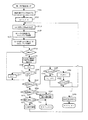
図8は、上記の複数タグ検出機能が選択されたときにリーダ1のCPU4によって実行される制御手順を表すフローチャートである。
FIG. 8 is a flowchart showing a control procedure executed by the
図8において、この例では、あらかじめ検出タグリスト(図7(b)参照)が作成されており、複数タグ検出機能が選択された状態で送信キー16が押下された際にこのフローが開始される。
In FIG. 8, in this example, a detection tag list (see FIG. 7B) is created in advance, and this flow is started when the
まず、ステップS5において、メモリ6(又は不揮発性記憶装置5)から上記検出タグリストを読み込んで、当該検出タグリストに記録されている書籍資料B又はタグIDの個数(つまり参照番号nの最大値;上記図7(b)に示す例では3)を変数Nの値として設定して次のステップS10へ移る。 First, in step S5, the detection tag list is read from the memory 6 (or the nonvolatile storage device 5), and the number of book materials B or tag IDs recorded in the detection tag list (that is, the maximum value of the reference number n). In the example shown in FIG. 7B, 3) is set as the value of the variable N, and the process proceeds to the next step S10.
次のステップS10では、RF通信制御部9に対し制御信号を出力することで送信出力の強度を最大に設定する。具体的には、RF通信制御部9に対して「TX−PWR」信号を最大の値で出力し、送信乗算回路216における増幅率を最大としてリーダアンテナ3から送信する電波の出力強度が最大となるよう制御する(図4参照)。これにより、リーダ1の最大通信可能領域の範囲内に存在する全ての無線タグT(図1に示す例では、棚板に並置されている全ての書籍資料Bにそれぞれ貼付されている無線タグTのうち通信範囲20の中にあるもの)に対して無線通信を行うことができるようになる。
In the next step S10, the intensity of the transmission output is set to the maximum by outputting a control signal to the RF
ステップS15では、変数Nの値が第1しきい値N1より少ないか否かを判定する。ここで、第1しきい値N1とは、各タグの存在確認のための読み取りを短時間で効率よく行う上で、上記個別指定方法による検出を選択すべき程度にNの値(タグIDの個数)が小さいか否かを判定する基準値である。なお、この第1しきい値N1の値は、上記図6に示した各コマンドの時間長や、それらコマンドの間の時間間隔に応じてあらかじめ適宜の値に設定される。変数Nの値が第1しきい値N1より小さい場合は、判定が満たされ、すなわち上記個別指定方法による検出を選択した方が効率的に行えるものとみなされ、ステップS100へ移る。 In step S15, it is determined whether or not the value of the variable N is smaller than the first threshold value N1. Here, the first threshold value N1 is a value of N (the tag ID of the tag ID) to the extent that the detection by the individual designation method should be selected in order to efficiently perform reading for confirming the presence of each tag in a short time. This is a reference value for determining whether or not (number) is small. Note that the value of the first threshold value N1 is set to an appropriate value in advance according to the time length of each command shown in FIG. 6 and the time interval between the commands. If the value of the variable N is smaller than the first threshold value N1, the determination is satisfied, that is, it is considered that the detection by the individual designation method can be performed more efficiently, and the process proceeds to step S100.
ステップS100では、上記個別指定方法により全てのタグIDを検出し、その後、それらタグIDに対応する全ての無線タグTに対してそれぞれの配置位置(リーダ1からの離間距離)を検出する個別指定タグID検出処理(詳細は後述の図9参照で説明する)を行う。そしてこのステップS100の手順を終えた後に、このフローを終了する。 In step S100, all the tag IDs are detected by the individual designation method, and then the individual designations for detecting the respective arrangement positions (separation distance from the reader 1) for all the radio tags T corresponding to the tag IDs. A tag ID detection process (details will be described later with reference to FIG. 9) is performed. And after finishing the procedure of this step S100, this flow is complete | finished.
また一方、上記ステップS15の判定において、変数Nの値がしきい値N1以上である場合、判定が満たされず、すなわち上記個別指定方法による検出を行うにはタグID(n)の個数が多すぎるものと判断され、ステップS20へ移る。 On the other hand, if the value of the variable N is greater than or equal to the threshold value N1 in the determination in step S15, the determination is not satisfied, that is, the number of tag IDs (n) is too large for detection by the individual designation method. If it is determined, the process proceeds to step S20.
ステップS20では、タグIDを指定しない(つまり全部のタグIDを通信対象として指定する)「Select」コマンドを生成し、リーダアンテナ3を介して送信する。これにより、リーダ1の通信可能領域(この時点では上記ステップS10の制御により最大通信可能領域)の範囲内に存在する全ての無線タグTがそれ以降の無線通信を行えるようになる。
In step S <b> 20, a “Select” command that does not specify tag IDs (that is, specifies all tag IDs as communication targets) is generated and transmitted via the
次にステップS25へ移り、スロット数指定値Qの値をこの例において3(つまり識別スロット数=2Q=23=8)とした「Query」コマンドを生成し、リーダアンテナ3を介して送信する。なお、上記のスロット数指定値Q=3の値は、リーダ1の通信可能領域に存在すると予想される全ての無線タグTの個数に応じて適宜設定され及び変更される設定値である。
Next, the process proceeds to step S 25, where a “Query” command is generated in which the value of the slot number designation value Q is 3 in this example (that is, the number of identification slots = 2 Q = 2 3 = 8), and is transmitted via the
次にステップS30へ移り、上記「Query」コマンドによって行われる第1識別スロット及びそれに続けて送信される「QueryRep」コマンドによって行われる第2〜第4識別スロットにおいて、「RN16」コマンドの衝突状態となった回数を調べる。なお、この例では衝突応答状態の回数だけを調べればよいため、「RN16」コマンドを受信した正常応答状態であってもその後の「Ack」コマンド、「タグ情報」の送受は省略してもよい。また、上記スロット指定値Qで設定される識別スロット数の全部で行う必要はなく、この例のように所定回数(適切な精度で後述する全タグ推定個数Xを推定できる回数)だけ衝突状態を調べて残りの識別スロットを省略し、効率化を図ることができる。 Next, the process proceeds to step S30. In the first identification slot performed by the “Query” command and the second to fourth identification slots performed by the “QueryRep” command transmitted subsequently, the collision state of the “RN16” command is determined. Find out how many times it became. In this example, it is only necessary to examine the number of collision response states. Therefore, even when the “RN16” command is received, the subsequent “Ack” command and “tag information” transmission / reception may be omitted. . Further, it is not necessary to carry out all the identification slot numbers set by the slot designation value Q, and the collision state is repeated a predetermined number of times (the number of times that the estimated total tag number X described later can be estimated with appropriate accuracy) as in this example. It is possible to improve efficiency by checking the remaining identification slots.
次にステップS35へ移り、「QueryAdjust」コマンドを生成し、リーダアンテナ3を介して送信する。この「QueryAdjust」コマンドとは、上記ステップS25でリーダ1から「Query」コマンドを受信した全ての無線タグT(無線タグ回路素子To)に対し、スロットカウンタ値Sなどの設定を全部リセットしてそれ以降の識別スロットに対する待機状態を解除するよう指令するコマンドである。つまり、この「QueryAdjust」コマンドを送信することで、上記ステップS25の「Query」コマンドによる読み取り処理が強制的に中断されることになる(上記図6では特に図示せず)。
Next, the process proceeds to step S 35, where a “QueryAdjust” command is generated and transmitted via the
次にステップS40へ移り、上記ステップS30で調べた「RN16」コマンドの衝突回数に基づいて、その時点でリーダ1の通信可能領域に存在する全ての無線タグTの個数、すなわち全タグ推定個数Xを推定算出する。このとき、詳細な説明や図示は省略するが、無線通信対象となっている全ての無線タグTの個数に対して識別スロット数が過度に不足している場合、その全識別スロットにわたって不足の度合いに応じた均一な頻度で「RN16」コマンドの衝突が生じることを利用して推定を行う。その際、上記「RN16」コマンドの衝突回数と共に、全識別スロット数(スロット数指定値Qの値)やそのうちの衝突状態を調べた識別スロット数(上記所定回数)も、併せて考慮して推定算出する。
Next, the process proceeds to step S40. Based on the number of collisions of the “RN16” command checked in step S30, the number of all wireless tags T existing in the communicable area of the
次にステップS45へ移り、上記ステップS40で算出した全タグ推定個数Xが第2しきい値N2以上であるか否かを判定する。ここで、第2しきい値N2とは、タグの存在確認のための読み取りを短時間で効率よく行う上で、上記個別指定方法による検出を選択すべき程度に無線タグTの推定個数が多いか否かを判定する基準値である。なお、この第2しきい値N2の値についても、上記図6に示した各コマンドの時間長や、それらコマンドの間の時間間隔に応じてあらかじめ設定される。 Next, the process proceeds to step S45, where it is determined whether or not the estimated total number of tags X calculated in step S40 is equal to or greater than the second threshold value N2. Here, the second threshold value N2 is an estimated number of RFID tags T to the extent that the detection by the individual designation method should be selected in order to efficiently perform reading for confirming the presence of the tag in a short time. This is a reference value for determining whether or not. The value of the second threshold value N2 is also set in advance according to the time length of each command shown in FIG. 6 and the time interval between the commands.
無線タグTの推定個数Xが第2しきい値N2以上である場合は、判定が満たされる。すなわち、無線タグTの個数が比較的多いために上記全指定方法による検出を行った場合には非効率的となることが予想され、逆に上記個別指定方法による検出を選択した方が効率的に行えるものとみなされて、ステップS100へ移る。そしてこのステップS100の手順を終えた後には、ステップS50へ移行する。 The determination is satisfied when the estimated number X of the wireless tags T is equal to or greater than the second threshold value N2. That is, since the number of RFID tags T is relatively large, it is expected that inefficiency is detected when detection is performed by the above-described all-designating method, and conversely, it is more efficient to select detection by the individual-designating method. Therefore, the process proceeds to step S100. And after finishing the procedure of this step S100, it transfers to step S50.
一方、無線タグTの推定個数Xが第2しきい値N2未満である場合は、判定が満たされない。すなわち非無線タグTbの推定個数が少ないためにムダな識別スロットが少なくなることが予想されるため、上記全指定方法による検出を選択した方が効率的に行えるものとみなされて、ステップS200へ移る。 On the other hand, when the estimated number X of the wireless tags T is less than the second threshold value N2, the determination is not satisfied. That is, since the estimated number of non-wireless tags Tb is small, it is expected that wasteful identification slots will be reduced. Therefore, it is considered that the detection by the above-described all-designating method can be performed more efficiently, and the process proceeds to step S200. Move.
ステップS200では、上記全指定方法により全てのタグIDを検出し、それらタグIDに対応する全ての無線タグTに対してそれぞれの配置位置(リーダ1からの離間距離)を検出する全指定タグID検出処理を行う(後述の図9参照)。そしてこのステップS200の手順を終えた後には、ステップS50へ移行する。 In step S200, all tag IDs that detect all tag IDs by the above-described all-specified method and detect the respective arrangement positions (separation distances from the reader 1) for all the radio tags T corresponding to the tag IDs are detected. A detection process is performed (see FIG. 9 described later). And after finishing the procedure of this step S200, it transfers to step S50.
ステップS50では、検出対象タグの数Nが0であるかどうか、すなわち検出対象となる全てのタグの検出が完了したかどうかを判断する。この判断が肯定される場合にはこのフローが終了され、否定された場合にはステップS10以降の処理が繰り返し行われる。 In step S50, it is determined whether or not the number N of detection target tags is 0, that is, whether or not detection of all tags to be detected has been completed. When this determination is affirmed, this flow is terminated, and when the determination is negative, the processes after step S10 are repeated.
以上のフローによる手順を行うことにより、無線タグTの個数が少ない場合には個別指定タグID検出処理を行い、一方、無線タグTの個数が多い場合には全指定タグID検出処理を行い、それぞれの処理の中で、全ての無線タグTのそれぞれの配置位置を検出することができる。 By performing the procedure according to the above flow, when the number of wireless tags T is small, an individually designated tag ID detection process is performed. On the other hand, when the number of wireless tags T is large, an all designated tag ID detection process is performed. In each process, the arrangement positions of all the wireless tags T can be detected.
図9は、図8中のステップS100において実行される複数タグ検出モードの詳細手順を表すフローチャートである。 FIG. 9 is a flowchart showing a detailed procedure of the multiple tag detection mode executed in step S100 in FIG.
まず、ステップS105において、変数Nの値が1であるか否か、つまり検出タグリストに記録されている無線タグTの個数が一つだけであるか否かを判定する。Nの値が2以上である場合、つまり無線タグTが複数ある場合、判定が満たされず、次のステップS110へ移る。なおNの値が1であった場合、つまり無線タグTが1個のみの場合、判定が満たされ、後述するステップS300へ移る。 First, in step S105, it is determined whether or not the value of the variable N is 1, that is, whether or not the number of wireless tags T recorded in the detection tag list is only one. When the value of N is 2 or more, that is, when there are a plurality of wireless tags T, the determination is not satisfied, and the routine goes to the next step S110. If the value of N is 1, that is, if there is only one wireless tag T, the determination is satisfied, and the routine goes to Step S300 described later.
ステップS110では、検出タグリストの参照番号に対応する変数nの値を1に設定し、次のステップS115へ移る。 In step S110, the value of the variable n corresponding to the reference number of the detection tag list is set to 1, and the process proceeds to the next step S115.
そしてステップS115では、検出タグリスト内で参照番号が変数nの値に対応するタグID(n)だけを指定する「Select」コマンドを生成し、リーダアンテナ3を介して発信する。なお、この時点では、上記図8のフローにおけるステップS10の手順によりリーダ1の送信出力が最大(通信可能領域が最大)となったままであるため、リーダ1の最大通信可能領域の範囲に存在する全ての無線タグTが上記「Select」コマンドを受信することになる。これにより、書棚の通信可能領域20内に載置されている複数の書籍資料Bに貼付されている無線タグTのうち、無線タグ回路素子Toのメモリ部155にID(n)が記憶されている無線タグTのみがそれ以降の無線通信を行えるようになり、すなわち当該タグID(n)の無線タグTとリーダ1とが1対1で情報の送受を行えるようになる。
In step S115, a “Select” command for designating only the tag ID (n) corresponding to the value of the variable n in the detection tag list is generated and transmitted via the
次にステップS120へ移り、スロット数指定値Qを0とした「Query」コマンドを生成してリーダアンテナ3を介し送信する。このようにスロット数指定値Qを0に設定した場合には識別スロットの数は一つだけ(識別スロット数=2Q=20=1)となり、またこの「Query」コマンドを受信した上記タグID(n)の無線タグ回路素子Toはスロットカウント値Sとして値0(=2Q−1=0)を生成する。これにより、タグID(n)の無線タグTは上記のスロット数指定値Q=0の「Query」コマンドを受信した際にその直後の第1識別スロットにおいて応答信号としての「RN16」コマンドをリーダ1に送信し、引き続き「Ack」コマンド、「タグ情報(タグIDを含む)」の送受を行うことになる(以上、図6参照)。
Next, the process proceeds to step S 120, where a “Query” command with the slot number designation value Q set to 0 is generated and transmitted via the
以上のような上記ステップS115及びステップS120の手順を行うことにより、「Select」コマンド、「Query」コマンドを用いるSlotted ALOHA方式の場合でも、多数個の無線タグTの中から特定の一つの無線タグT(タグID(n)のもの)に対してだけ最短の時間(識別スロット数=1)で当該無線タグTの存在の確認と情報の送受を行うことができる。 By performing the steps S115 and S120 as described above, even in the case of the Slotted ALOHA method using the “Select” command and the “Query” command, one specific wireless tag from among a large number of wireless tags T is used. The presence of the wireless tag T can be confirmed and information can be transmitted and received in the shortest time (number of identification slots = 1) only for T (tag ID (n)).
そして次のステップS125へ移り、上記ステップS120で送信した「Query」コマンドに対する応答信号(「RN16」コマンド)が受信できたか否か、つまりタグIDがタグID(n)である無線タグTから応答があったか否かを判定する。ここで応答がなかった場合、判定は満たされず、すなわちリーダ1の最大通信可能領域(上記図8のステップS10参照)の範囲内にタグID(n)の無線タグTが存在しない(又は上記ステップS115、ステップS120の無線通信が失敗した)ものとみなされて次のステップS130へ移る。 Then, the process proceeds to the next step S125, whether or not a response signal (“RN16” command) to the “Query” command transmitted in step S120 has been received, that is, a response from the wireless tag T whose tag ID is the tag ID (n). It is determined whether or not there was. If there is no response here, the determination is not satisfied, that is, the RFID tag T with the tag ID (n) does not exist within the range of the maximum communicable area of the reader 1 (see step S10 in FIG. 8 above) (or the above step). S115, the wireless communication in step S120 is considered to have failed), and the process proceeds to the next step S130.
ステップS130では、変数nの値が変数Nの値以上であるか否かを判定する。変数nの値が変数Nの値以上である場合、判定は満たされ、すなわち検出タグリストに記録されているタグID(n)に対して順に「Select」コマンド及び「Query」コマンドで呼びかけたところいずれかの無線タグTから応答がない(または通信失敗した)ものとみなされ、ステップS135で変数nの値を1に戻してからステップS115へ戻り、同様の手順を繰り返して一つ目の無線タグTから再度無線通信を行う。 In step S130, it is determined whether or not the value of variable n is equal to or greater than the value of variable N. When the value of the variable n is equal to or greater than the value of the variable N, the determination is satisfied, that is, the tag ID (n) recorded in the detection tag list is sequentially called with the “Select” command and the “Query” command. It is assumed that there is no response from one of the wireless tags T (or communication has failed), the value of the variable n is returned to 1 in step S135, and the process returns to step S115. Wireless communication is performed again from the tag T.
一方、変数nの値が変数Nの値より小さい場合、判定は満たされず、ステップS140で変数nの値を1つ増加してからステップS115へ戻り、検出タグリストにおける次の無線タグTに対して無線通信を行う。 On the other hand, if the value of the variable n is smaller than the value of the variable N, the determination is not satisfied, the value of the variable n is incremented by 1 in step S140, and the process returns to step S115, for the next wireless tag T in the detection tag list Wireless communication.
また、一方、上記ステップS125の判定において、タグID(n)の無線タグTから応答があったか場合、判定は満たされ、すなわちリーダ1の最大通信可能領域の範囲内においてタグID(n)の無線タグTの存在を確認できたものとみなされてステップS300の単一タグ検出モードへ移る。
On the other hand, if it is determined in step S125 that there is a response from the wireless tag T with the tag ID (n), the determination is satisfied, that is, the wireless communication with the tag ID (n) is within the maximum communicable area of the
上記ステップS105又はステップS125から移ったステップS300では、単一タグ検出モードを実行し、ID(n)の無線タグTとの間で無線通信を行うことにより当該無線タグTからリーダ1までの離間距離を検出する(後述の図11参照)。
In step S300 moved from step S105 or step S125, the single tag detection mode is executed, and wireless communication is performed with the wireless tag T of ID (n), thereby separating the wireless tag T from the
その後、このフローを終了し、図8に示すフローに戻ってステップS50以下の処理を続行する。 Thereafter, this flow is ended, and the flow returns to the flow shown in FIG. 8 to continue the processing from step S50.
なお、図9に示すフローの各手順のうち、ステップS300以外のステップS105〜ステップS140が、各請求項記載の複数タグ検出モードに相当する。 Of steps in the flow shown in FIG. 9, steps S105 to S140 other than step S300 correspond to the multiple tag detection mode described in each claim.
以上のフローによる手順を行うことにより、検出タグリストにタグIDが一つだけ記憶されている場合にはそのまますぐに単一位置検出モードで当該タグIDに対応する無線タグTの配置位置を検出する。検出タグリストに複数個のタグID(n)が記憶されている場合にはそれぞれのタグID(n)に対応する無線タグTがリーダ1の最大通信可能領域の範囲内に存在しているかを上記個別指定方法により確認し、存在が確認できた無線タグTに対して単一タグ検出モードで配置位置を検出することができる。
By performing the procedure according to the above flow, when only one tag ID is stored in the detection tag list, the arrangement position of the wireless tag T corresponding to the tag ID is immediately detected in the single position detection mode. To do. When a plurality of tag IDs (n) are stored in the detection tag list, it is determined whether the wireless tag T corresponding to each tag ID (n) exists within the maximum communicable area of the
図10は、図8中のステップS200において実行される全指定タグID検出処理の詳細手順を表すフローチャートである。 FIG. 10 is a flowchart showing the detailed procedure of the all-specified tag ID detection process executed in step S200 in FIG.
まず、ステップS201において、フローの繰り返し数をカウントするための変数kを0とし、次に、ステップS205において、上記図8のフローにおけるステップS40で推定算出した全タグ推定個数Xに基づき、リーダ1の最大通信可能領域に存在するこの個数の無線タグTどうしが「RN16」コマンドを衝突させることなく確実に全ての無線タグTと情報の授受が行えるだけの十分な数の識別スロット数を算出する。そして、この識別スロット数に対応するスロット数指定値Qmaxを算出する。 First, in step S201, the variable k for counting the number of repetitions of the flow is set to 0. Next, in step S205, based on the estimated total number of tags X calculated in step S40 in the flow of FIG. A sufficient number of identification slots is calculated so that the number of RFID tags T existing in the maximum communicable area can reliably exchange information with all the RFID tags T without colliding the “RN16” command. . Then, a slot number designation value Qmax corresponding to the number of identification slots is calculated.
次にステップS210へ移り、識別スロットの参照変数となるカウンタ変数Cの値を1に設定し、次のステップS211へ移る。 Next, the process proceeds to step S210, the value of the counter variable C serving as the reference variable for the identification slot is set to 1, and the process proceeds to the next step S211.
ステップS211において、タグIDを指定しない(つまり全部のタグIDを通信対象として指定する)「Select」コマンドを生成し、リーダアンテナ3を介して送信する。これにより、リーダ1の通信可能領域(この時点では上記ステップS10の制御により最大通信可能領域)の範囲内に存在する全ての無線タグTがそれ以降の無線通信を行えるようになる。その後、ステップS215において、スロット数指定値Q=Qmaxとした「Query」コマンドを生成してリーダアンテナ3を介し送信する。なお、この時点では、上記図8のフローにおけるステップS10の手順によりリーダ1の送信出力が最大(通信可能領域が最大)となったままであり、さらにこの処理を最初に行なう場合(k=0のとき)はステップS11の手順で、それ以降は後述するステップS264の手順でタグIDを指定しない「Select」コマンドを送信しているため、リーダ1の最大通信可能領域の範囲に存在する全ての無線タグTが上記「Query」コマンドを受信することになる。このようにスロット数指定値QをQmaxに設定した場合には、識別スロット数が予定として2^Qmaxの数だけ用意されることになり(後述するように途中で中断する場合もある)、またこの「Query」コマンドを受信した全ての無線タグTの無線タグ回路素子Toがスロットカウント値Sとして0〜(2^Qmax−1)の乱数を生成する。
In step S211, a “Select” command that does not specify tag IDs (that is, specifies all tag IDs as communication targets) is generated and transmitted via the
なお、上記図8のフローにおけるステップS30の手順では、衝突や空スロットの有無を調べるために識別スロットの数がある程度制限(この例では8つ用意できるところを4つに制限)される。これに対して、この全タグ応答モードでは、通信可能領域の全ての無線タグTの応答信号を受信する必要がある。そこで、上記図8のフローにおけるステップS30の手順よりスロット数を多くすることで、円滑な受信が可能となる。 In the procedure of step S30 in the flow of FIG. 8, the number of identification slots is limited to some extent (in this example, the number that can be prepared is limited to four) in order to check the presence or absence of a collision or an empty slot. On the other hand, in this all tag response mode, it is necessary to receive response signals from all the wireless tags T in the communicable area. Therefore, smooth reception is possible by increasing the number of slots compared to the procedure of step S30 in the flow of FIG.
次にステップS220へ移り、この時点でスロットカウント値Sが0となっている無線タグTからの応答信号として「RN16」コマンドを受信したか否かを判定する。この判定において、「RN16」コマンドが受信された場合、判定が満たされ、すなわち当該識別スロットで応答する無線タグTが存在するとみなされて、次のステップS225へ移る。 Next, the process proceeds to step S220, and it is determined whether or not the “RN16” command is received as a response signal from the wireless tag T whose slot count value S is 0 at this time. In this determination, when the “RN16” command is received, the determination is satisfied, that is, it is considered that there is a wireless tag T responding in the identification slot, and the process proceeds to the next step S225.
ステップS225では、上記ステップS220で受信された「RN16」コマンドに含まれている疑似乱数に対応する内容の「Ack」コマンドを送信する。そして、次のステップS230で無線タグTからその識別情報であるタグIDを含むタグ情報を受信した後、次のステップS235へ移る。 In step S225, an “Ack” command having a content corresponding to the pseudorandom number included in the “RN16” command received in step S220 is transmitted. Then, after receiving tag information including the tag ID which is the identification information from the wireless tag T in the next step S230, the process proceeds to the next step S235.
ステップS235では、上記ステップS230で受信したタグIDが検出タグリストに記憶されているタグIDのいずれかであるか否かを判定する。受信したタグIDが検出タグリストに記憶されているタグIDである場合、判定は満たされ、次のステップS265へ移る。 In step S235, it is determined whether the tag ID received in step S230 is one of the tag IDs stored in the detection tag list. If the received tag ID is a tag ID stored in the detection tag list, the determination is satisfied, and the routine goes to the next Step S265.
また一方、上記ステップS220の判定において、「RN16」コマンドが受信されていない場合、判定が満たされず、すなわち当該識別スロットで応答する無線タグTがないものとみなされて、ステップS250へ移る。 On the other hand, if the “RN16” command is not received in the determination in step S220, the determination is not satisfied, that is, it is considered that there is no wireless tag T responding in the identification slot, and the process proceeds to step S250.
また一方、上記ステップS235の判定において、受信したタグIDが受信したタグIDが検出タグリストに記憶されているタグIDでなかった場合、判定は満たされず、ステップS250へ移る。 On the other hand, if it is determined in step S235 that the received tag ID is not the tag ID stored in the detection tag list, the determination is not satisfied and the process proceeds to step S250.
このようにしてステップS220、又はステップS235から移ったステップS250では、カウンタ変数Cの値が2^Qmaxより小さいか否か、すなわち最後の識別スロットを終了したか否かを判定する。カウンタ変数Cの値が2^Qmaxより小さい場合、判定が満たされ、すなわち現行の「Query」コマンドによる読み取り処理が終了していないものとみなされて、次のステップS255へ移る。 In this way, in step S220 moved from step S220 or step S235, it is determined whether or not the value of the counter variable C is smaller than 2 ^ Qmax, that is, whether or not the last identification slot has ended. If the value of the counter variable C is smaller than 2 ^ Qmax, the determination is satisfied, that is, it is considered that the reading process by the current “Query” command is not completed, and the process proceeds to the next step S255.
ステップS255では、カウンタ変数Cの値に1を加え、次にステップS260で「QueryRep」コマンドをリーダアンテナ3から送信して次の識別スロットを開始してからステップS220へ戻り同様の手順を繰り返す。ここで、この「QueryRep」コマンドを受信した全ての無線タグTの無線タグ回路素子Toは、そのメモリ部155が記憶しているスロットカウント値Sの値を一つ減算し、その時点でスロットカウント値Sが0になった無線タグTが新しい識別スロットで「RN16」コマンドを送信するようになる(そしてリーダ1が、次のステップS220でこの「RN16」コマンドを受信する)。
In step S255, 1 is added to the value of the counter variable C. Next, in step S260, a “QueryRep” command is transmitted from the
また一方、上記ステップS250の判定において、カウンタ変数Cの値が2^Qmax以上である場合、判定が満たされず、すなわち検出タグリストに記録されているいずれかの無線タグTから応答がない(または通信失敗した)まま現行の「Query」コマンドによる読み取り処理が終了(最後の識別スロットが終了)したものとみなされる。この場合、ステップS261において同じ状態で行なわれた全指定タグID検出処理の回数を示す変数kに1が加えられたのち、ステップS262において前記変数kが規定の値kmaxと等しいかどうかが判定される。この判定が肯定される場合は、図10に示す全指定タグID検出処理を終了し、図8に示すフローへ戻ってS50以下の処理を行う。一方、ステップS262の処理が否定された場合、S264においてタグIDを指定しない(つまり全部のタグIDを通信対象として指定する)「Select」コマンドを生成し、リーダアンテナ3を介して送信した後、ステップS210へ戻って同様の手順を繰り返して第1識別スロットからの新たな読み取り処理を行う。
On the other hand, if the value of the counter variable C is 2 ^ Qmax or more in the determination in step S250, the determination is not satisfied, that is, there is no response from any of the wireless tags T recorded in the detection tag list (or It is assumed that the reading process by the current “Query” command has been completed (the last identification slot has been completed) while communication has failed. In this case, after 1 is added to the variable k indicating the number of all designated tag ID detection processes performed in the same state in step S261, it is determined whether or not the variable k is equal to the specified value kmax in step S262. The If this determination is affirmative, the all-specified tag ID detection process shown in FIG. 10 is terminated, and the process returns to the flow shown in FIG. On the other hand, if the process of step S262 is denied, a “Select” command that does not specify tag IDs in S264 (that is, specifies all tag IDs as communication targets) is generated and transmitted via the
また一方、上記ステップS235の判定において、判定が満たされる場合、検出対象となるタグが検出されたものとみなされ、次のステップS265へ移る。 On the other hand, if the determination in step S235 is satisfied, it is considered that the tag to be detected has been detected, and the process proceeds to the next step S265.
ステップS265では、リーダアンテナ3を介して「QueryAdjust」コマンドを全ての無線タグTに送信し、現行の「Query」コマンドによる読み取り処理を強制的に中断する。
In step S265, the “QueryAdjust” command is transmitted to all the wireless tags T via the
その後、上記と同様のステップS300において単一タグ検出モードを実行し、検出された(タグID(n)の)無線タグTとの間で無線通信を行うことにより当該無線タグTからリーダ1までの離間距離を検出し(後述の図11参照)、この処理が完了したら、このフローを終了する。
Thereafter, the single tag detection mode is executed in the same step S300 as described above, and wireless communication is performed with the detected wireless tag T (with tag ID (n)) from the wireless tag T to the
以上のフローによる手順を行うことにより、検出タグリストに記憶されている複数のタグID(n)に対応する無線タグTがリーダ1の最大通信可能領域の範囲内に存在しているかを上記全指定方法により確認し、いずれかの無線タグTの存在が確認できた場合に単一タグ検出モードで配置位置を検出することができる。
By performing the procedure according to the above flow, whether or not the wireless tag T corresponding to the plurality of tag IDs (n) stored in the detection tag list is within the range of the maximum communicable area of the
図11は、図9、図10中のステップS300において実行される単一タグ検出モードの詳細手順を表すフローチャートである。 FIG. 11 is a flowchart showing a detailed procedure of the single tag detection mode executed in step S300 in FIGS.
まず、ステップS305において、表示部8に制御信号を出力して探索対象のタグID(n)(変数nの内容は上記図9、図10での値を継続)の内容を表示部8に表示する。その後、次のステップS310で送信出力のレベルに対応する変数Lv(例えばLv=1〜10の10段階等で変化する)の値を1(すなわち最小)に、検出の失敗回数に対応する変数Fの値を0に初期設定する。
First, in step S305, a control signal is output to the
次にステップS315へ移り、変数Lvの値に対応してリーダ1の送信出力の強度を設定する。具体的には、上記図8のフローにおけるステップS10の手順と同様に、RF通信制御部9に対して変数Lvの値に対応する「TX−PWR」信号を出力し、送信乗算回路216における増幅率を制御する。これにより、上記変数Lvが1〜10の10段階で変化することに対応してリーダ1の送信出力も10段階で増減制御される。なお、上記ステップS310で変数Lvが1に初期設定された直後である場合には、リーダ1の送信出力は最も低い強度に設定され、変数Lvの増加に対応して送信出力も増加(上記の例では変数Lv=10で送信出力が最大)するものとなる。
In step S315, the intensity of the transmission output of the
そして次のステップS320で、タグID(n)だけを指定する「Select」コマンドをリーダアンテナ3から送信し、ステップS325でスロット数指定値Qを0として「Query」コマンドをリーダアンテナ3から送信する。これらステップS320とステップS325の手順は、それぞれ上記図9のフローにおけるステップS115とステップS120の手順と同様の制御を行うものであり、これによってタグID(n)の無線タグTとだけ最短の時間で無線通信を介した呼びかけ(応答要求)を行う。
Then, in the next step S320, a “Select” command for designating only the tag ID (n) is transmitted from the
そして次のステップS330で、上記図9のフローにおけるステップS125の手順と同様に、タグID(n)の無線タグTから応答があったか否かを判定する。ここで応答があった場合、判定が満たされ、すなわちその時点における変数Lvの送信出力に対応するリーダ1の通信可能領域20の範囲内にタグID(n)の無線タグTが存在しているものとみなされ、次のステップS335に移る。
Then, in the next step S330, it is determined whether or not there is a response from the wireless tag T with the tag ID (n) as in the procedure of step S125 in the flow of FIG. If there is a response, the determination is satisfied, that is, the wireless tag T with the tag ID (n) exists within the
ステップS335では、その時点の変数Lvに対応するリーダ1からの離間距離を所定の演算により算出する。そして、この距離を表示部8に表示する(報知手段)。この離間距離の表示は、変数Lvに対応する送信出力により形成されるリーダ1の通信可能領域20の最長距離(つまりリーダアンテナ3から通信可能領域20の先端までの離間距離)を表示するものであり、タグID(n)の無線タグTが存在する可能性のあるリーダ1からの範囲を示している。
In step S335, the separation distance from the
次にステップS340へ移り、変数Fの値を0に再設定する。さらにステップS341において変数Lvが1以上であるかを判定する。この判定が満たされる場合は、直接次のステップS345へ移り、否定される場合はステップS342において変数Lvを1とした後にステップ345へ移る。 Next, the process proceeds to step S340, and the value of the variable F is reset to 0. In step S341, it is determined whether the variable Lv is 1 or more. If this determination is satisfied, the process proceeds directly to the next step S345, and if negative, the variable Lv is set to 1 in step S342 and then the process proceeds to step 345.
また一方、上記ステップS330の判定において、タグID(n)の無線タグTから応答がなかった場合、判定が満たされず、すなわちその時点における変数Lvの送信出力に対応するリーダ1の通信可能領域20の範囲内にタグID(n)の無線タグTが存在しないものとみなされ、そのままステップS345へ移る。
On the other hand, if no response is received from the wireless tag T with the tag ID (n) in the determination in step S330, the determination is not satisfied, that is, the
ステップS345では、リーダ1を操作する使用者から操作部7を介して何らかの入力操作が行われたか否かを判定する。何も入力操作が行われていない場合、判定が満たされず、次のステップS350へ移る。
In step S345, it is determined whether or not an input operation has been performed by the user operating the
ステップS350では、変数Lvの値が最大値Lvmax(この例では10)と同じ値であるか否かを判定する。変数Lvの値が最大値Lvmaxと異なる(最大値Lvmaxより低い)場合、つまり変数Lvの値がまだ最大値に達していない場合、判定が満たされず、次のステップS355で変数Lvの値を1増加した後、ステップS315へ戻って同様の手順を繰り返す。 In step S350, it is determined whether or not the value of the variable Lv is the same value as the maximum value Lvmax (10 in this example). If the value of the variable Lv is different from the maximum value Lvmax (lower than the maximum value Lvmax), that is, if the value of the variable Lv has not yet reached the maximum value, the determination is not satisfied and the value of the variable Lv is set to 1 in the next step S355. After the increase, the process returns to step S315 and the same procedure is repeated.
一方、上記ステップS345の判定において、操作部7に何らかの入力操作が行われている場合、判定が満たされ、ステップS360へ移る。
On the other hand, in the determination in step S345, if any input operation is performed on the
ステップS360では、上記ステップS345で検出された入力操作が、「目視発見」に対応する入力操作であるか否かを判定する。ここで目視発見とは、上記ステップS335における無線タグTの検出位置の表示を参照したこと等により、使用者が探索対象の書籍資料Bを目視により発見したことである。すなわち、単一タグ検出モードは、タグID(n)の無線タグTの配置位置が検出・表示された後でも引き続き無線通信を繰り返すが、上記のように発見した場合には、(この無線タグTについては目的が達せられたため)リーダ1によるタグID(n)の無線タグTの配置位置の探索をこれ以上行う必要がなくなる。したがって、当該タグID(n)の無線タグTを検出する単一タグ検出モードを中止するべく使用者が意思表示として対応する入力操作を行えるようにしているものである(後述の図12(c)参照)。「目視発見」に対応する入力操作が行われた場合、判定が満たされ、ステップS365で検出タグリストからタグID(n)に関する情報(この例ではタグID(n)と資料名)を削除し、このフローを終了する。この結果、単一タグ検出モードを終了して図9のステップS160又は図10のステップS275へ移行する。一方、「目視発見」に対応する入力操作が行われていない場合、判定が満たされず、次のステップS370へ移る。
In step S360, it is determined whether or not the input operation detected in step S345 is an input operation corresponding to “visual discovery”. Here, the visual discovery means that the user has visually discovered the book material B to be searched by referring to the display of the detection position of the wireless tag T in step S335. That is, in the single tag detection mode, the wireless communication is continuously repeated even after the arrangement position of the wireless tag T with the tag ID (n) is detected and displayed. Since the purpose of T has been achieved, the
ステップS370では、上記ステップS345で検出された入力操作が、この単一タグ検出モードを終了する(図9の複数タグ検出モード、又は図10の全タグ応答モードへ戻る)「RETURN」に対応する入力操作であるか否かを判定する。すなわち、タグID(n)の無線タグTと無線通信できずに長時間検出動作を繰り返している場合でも、使用者が当該無線タグTの検出を断念して任意に複数タグID検出モードへ戻るために(意思表示として)「RETURN」の入力操作を行えるようにしている。 In step S370, the input operation detected in step S345 corresponds to “RETURN” that ends the single tag detection mode (returns to the multiple tag detection mode in FIG. 9 or the all tag response mode in FIG. 10). It is determined whether or not the operation is an input operation. That is, even when wireless communication with the wireless tag T with the tag ID (n) is not possible and the detection operation is repeated for a long time, the user gives up detection of the wireless tag T and arbitrarily returns to the multiple tag ID detection mode. Therefore, an input operation of “RETURN” can be performed (as an intention display).
「RETURN」に対応する入力操作が行われている場合、判定が満たされ、このフローを終了する(すなわち図9のステップS160又は図10のステップS275へ移行する)。なお、図9のステップS160へ移行する場合には、対応する無線タグTのタグIDを検出タグリストに残したままの状態で図9の複数タグ検出モードへ戻ることとなる。これにより、対象の無線タグT(又は書籍資料B)は未だ発見に至っていないことに対応してタグIDは検出タグリストから削除せず残しつつ(別の機会で改めて位置検出処理を行う可能性があるため)、別の無線タグTに対し複数タグ検出モードにて探索を続行することができる。また単一タグ検出モードに切り替えた後に無線タグTを使用者が見失った場合に、再度複数タグ検出モードからやり直すことも可能である。 When the input operation corresponding to “RETURN” is performed, the determination is satisfied, and this flow is ended (that is, the process proceeds to step S160 in FIG. 9 or step S275 in FIG. 10). In addition, when moving to step S160 in FIG. 9, the tag return to the multiple tag detection mode in FIG. 9 is performed with the tag ID of the corresponding wireless tag T remaining in the detection tag list. Accordingly, there is a possibility that the tag ID is not deleted from the detection tag list corresponding to the fact that the target wireless tag T (or book material B) has not yet been discovered (position detection processing may be performed again at another opportunity). Therefore, the search can be continued in the multiple tag detection mode for another wireless tag T. In addition, when the user loses sight of the wireless tag T after switching to the single tag detection mode, it is possible to start over from the multiple tag detection mode again.
一方、「RETURN」に対応する入力操作が行われていない場合、判定が満たされず、次のステップS375へ移り、上記ステップS345で検出された入力操作を無視してステップS350へ移る。 On the other hand, if the input operation corresponding to “RETURN” is not performed, the determination is not satisfied, and the process proceeds to the next step S375, and the input operation detected in step S345 is ignored, and the process proceeds to step S350.
また一方で、上記ステップS350の判定において、変数Lvの値が最大値Lvmax(この例では10)と同じである場合、つまり変数Lvの値が最大値に達している場合、判定が満たされ、ステップS380へ移る。 On the other hand, if the value of the variable Lv is the same as the maximum value Lvmax (10 in this example) in the determination in step S350, that is, if the value of the variable Lv has reached the maximum value, the determination is satisfied. The process moves to step S380.
ステップS380では、変数Fの値が1増加される。これにより、変数Lvに対応する送信出力を順に全ての段階で一通り変化させ、Lv=10にて最大出力で通信を行ってもタグID(n)の無線タグTを検出できなかったことになり、このような最大送信出力での失敗回数Fが1増加したことになる。 In step S380, the value of variable F is incremented by one. As a result, the transmission output corresponding to the variable Lv is changed in order at all stages in order, and even when communication is performed with the maximum output at Lv = 10, the wireless tag T with the tag ID (n) cannot be detected. Thus, the number of failures F at such maximum transmission output is increased by one.
そして次のステップS385で、上記失敗回数に対応する変数Fの値が最大値Fmaxと同じ値であるか否かを判定する。変数Fの値が最大値Fmaxと異なる(最大値Fmaxより低い)場合、つまり変数Fの値がまだ最大値に達していない場合、判定が満たされず、ステップS315へ戻って同様の手順を繰り返す。 In the next step S385, it is determined whether or not the value of the variable F corresponding to the number of failures is the same as the maximum value Fmax. If the value of the variable F is different from the maximum value Fmax (lower than the maximum value Fmax), that is, if the value of the variable F has not yet reached the maximum value, the determination is not satisfied and the process returns to step S315 and the same procedure is repeated.
一方、変数Fの値が最大値Fmaxと同じである場合、つまり変数Fの値が最大値に達している場合、判定が満たされ、次のステップS390で表示部8にタグID(n)の無線タグTの検出に失敗した旨を表示した後、このフローを終了する。すなわちこの例では、単一タグ検出モードにおいて位置検出用の通信を開始後、所定の通信回数分読み取りに失敗した場合には、上記ステップS385の判定手順により、複数タグ検出モード又は全タグ応答モードへ自動的に切り替える(すなわち図9のステップS160又は図10のステップS275へ移行する)。位置検出用通信が所定回数以上失敗している無線タグT(又は書籍資料B)については、例えば対応する無線タグT(又は書籍資料B)が移動するなどで通信範囲から外れたことが考えられ、これ以上位置検出を続行しても時間のロスによる不利益のほうが大きいとみなすのである。図9のステップS160へ移行する場合は、検出対象となる無線タグTが未だ発見に至っていないことに対応してタグIDはリストから削除せず残しつつ(別の機会で改めて位置検出処理を行う可能性があるため)、別の無線タグTに対し複数タグ検出モードにて探索を続行するものである。
On the other hand, if the value of the variable F is the same as the maximum value Fmax, that is, if the value of the variable F has reached the maximum value, the determination is satisfied, and the tag ID (n) is displayed on the
以上のフローによる手順を行うことにより、タグID(n)の無線タグT一つのみが探索されてそのリーダ1からの離間距離が表示部8に表示され、使用者からの「目視発見」又は「RETURN」の入力操作が行われた際にこのフローが終了する。又は、タグID(n)の無線タグTが貼付された書籍資料Bが持ち出されたり、電波環境の悪化などで無線通信が長時間継続的に失敗して所定の時間が経過した場合でもこのフローを終了する。
By performing the procedure according to the above flow, only one RFID tag T with the tag ID (n) is searched and the distance from the
なお、操作者が探索を開始する際に、上記のように複数タグ検出機能が選択された状態で送信キー16が押下されるのではなく、単一タグ検出機能が選択されて送信キー16が押下された場合には、図11のフローのみが実行される(ステップS390が終了したらそのままENDとなる)。
When the operator starts the search, the
図12は、リーダ1の作動中における液晶パネル11の表示例を表す図である。いずれも複数タグ検出機能が選択されている場合を例にとって示している。
FIG. 12 is a diagram illustrating a display example of the
図12(a)は、上記図8に示した処理を実行する前(つまり送信キー16を押下する前)の状態で、検出タグリストを作成している時点における液晶パネル11の表示例を示している。
FIG. 12A shows a display example of the
この図12(a)において、液晶パネル11には登録タグリストに登録されている資料名の一部が列記されており、図示する例では使用者は上下に対応する2つの方向キー(選択操作手段)14U,14Dを押下操作することでカーソルC(図中の破線で示す四角枠)を移動させる(なお、カーソルCを移動し続けることでその他の資料名を表示させることも可能)。そして、探索を希望する資料名をこのカーソルCで囲んだ際に決定キー(選択操作手段)15を押下することで、当該資料名と対応するタグIDが登録タグリストから選択抽出されて検出タグリストに記憶保持される。このようにして行われる操作により検出タグリストが作成される。
In FIG. 12A, a part of the material names registered in the registration tag list is listed on the
図12(b)は、上記のようにして作成された検出タグリストで対象として3個の無線タグTが指定されて、上記図9に示した(個別指定タグID検出モードである)ステップS105〜ステップS140の手順もしくは上記図10に示した(全タグ検出モードである)ステップS210〜ステップS260の手順を実行している時点における液晶パネル11の表示例を示している。図示する表示例では、送信出力が最大出力状態にほぼ相当する状態(塗りつぶされた四角枠が3つ)であることを表示している。
In FIG. 12B, three wireless tags T are designated as targets in the detection tag list created as described above, and step S105 shown in FIG. 9 (individually designated tag ID detection mode) is performed. 11 shows a display example of the
図12(c)は、上記のようにして個別タグID検出モードもしくは全タグ検出モードを実行して検出タグリストに記載された無線タグTが見つかった後、単一タグ検出モードに切り替えて無線タグTの位置検出を行っている場合の表示例を表す図である。この例では、「プロジェクトA仕様書」の書籍資料Bに貼付されている無線タグT(タグIDが「80000157」)の位置検出中の例を示している。図示の例では、送信出力が中程度の大きさを表す「2」(塗りつぶされた四角枠が2つ)の段階の出力状態であることを表示している。 FIG. 12C shows a case where the individual tag ID detection mode or the all tag detection mode is executed as described above, and the wireless tag T described in the detection tag list is found, and then the single tag detection mode is switched to the wireless tag. It is a figure showing the example of a display in case the position detection of the tag T is performed. In this example, an example in which the position of the wireless tag T (tag ID “80000157”) attached to the book material B of the “project A specification” is being detected is shown. In the example shown in the figure, the output state of “2” (two filled square frames) representing a medium transmission output is displayed.
また、この例では、左方向に対応する方向キー(第1操作手段)14Lが「目視発見」に対応しており、図示する表示状態の際に左方向の方向キー14Lを押下することで、検出タグリストから「プロジェクトA仕様書」に対応する情報が削除(図11のステップS365参照)された後、図9のステップS160又はステップS10のステップS275へ移行する。 Further, in this example, the direction key (first operation means) 14L corresponding to the left direction corresponds to “visual discovery”, and by pressing the left direction key 14L in the illustrated display state, After the information corresponding to the “project A specification” is deleted from the detection tag list (see step S365 in FIG. 11), the process proceeds to step S160 in FIG. 9 or step S275 in step S10.
また、この例では、右方向に対応する方向キー(第2操作手段)14Rが「RETURN」に対応している。図示する表示状態の際に右方向の方向キー14Rを押下することで、図9のステップS160又はステップS10のステップS275へ移行する。 In this example, the direction key (second operation means) 14R corresponding to the right direction corresponds to “RETURN”. When the right direction key 14R is pressed in the illustrated display state, the process proceeds to step S160 in FIG. 9 or step S275 in step S10.
以上において、上記図8のフローにおけるステップS20〜ステップS40の手順がタグ数推測手段を構成する。 In the above, the procedure from step S20 to step S40 in the flow of FIG. 8 constitutes the tag number estimating means.
また、上記図11のフローにおけるステップS310、ステップS315、ステップS340、及びステップS355の手順が出力制御手段を構成する。またステップS350の手順が第1判定手段を構成する。 Further, the procedure of step S310, step S315, step S340, and step S355 in the flow of FIG. 11 constitutes an output control means. Further, the procedure of step S350 constitutes a first determination unit.
また、上記図8のフローにおける上記ステップS15及びステップS45の手順と、上記図9のフローにおけるステップS105、ステップS125の手順と、上記図10のフローにおけるステップS235の手順と、上記図11のフローにおけるステップS360、ステップS370、及びステップS385の手順が、がモード切替手段を構成する。 Further, the procedure of steps S15 and S45 in the flow of FIG. 8, the procedure of steps S105 and S125 in the flow of FIG. 9, the procedure of step S235 in the flow of FIG. 10, and the flow of FIG. Steps S360, S370, and S385 in the above form a mode switching means.
また、上記図8のフローにおけるステップS25の手順が推測用送信制御手段を構成し、ステップS25で送信する「Query」コマンドが全タグ読み取りコマンドを構成し、またステップS30の手順が推測用受信制御手段を構成する。 Further, the procedure of step S25 in the flow of FIG. 8 constitutes the estimation transmission control means, the “Query” command transmitted in step S25 constitutes the all tag reading command, and the procedure of step S30 is the estimation reception control. Configure the means.
また、上記図10のフローにおけるステップS215の手順が全タグ送信制御手段を構成し、ステップS215で送信する「Query」コマンドが全タグ読み取りコマンドを構成し、またステップS220及びステップS230の手順が全タグ受信制御手段を構成する。 Further, the procedure of step S215 in the flow of FIG. 10 constitutes all tag transmission control means, the “Query” command transmitted in step S215 constitutes an all tag reading command, and the procedures of step S220 and step S230 are all A tag reception control unit is configured.
また、上記図11のフローにおけるステップS365の手順が削除処理手段として機能する。 Further, the procedure of step S365 in the flow of FIG. 11 functions as a deletion processing unit.
以上説明したように、本実施形態のリーダ1においては、まず上記図8のフローにおけるステップS20〜ステップS40の手順で、リーダ1の通信可能領域(周辺領域)における全タグ推定個数Xを推測する。このとき、上記図8のフローにおけるステップS40において、受信状況として、応答信号の衝突が生じている識別スロットの数に基づき、通信可能領域における全タグ推定個数Xを推測する。これにより、衝突状態の生じている識別スロットの数が多い場合には、通信可能領域における全タグ推定個数Xが比較的多いと推測することができる。そして、上記図8のフローにおけるステップS45において、上記全タグ推定個数Xに応じ、モードの切り替えを実行する。すなわち、推測した通信可能領域内の全タグ推定個数Xが比較的少なかった場合には、全タグ応答モードで周辺の全無線タグTの情報取得を行ないつつ順次検出タグリストとの照合を行い検出タグリスト内のタグを受信したかどうかを調べる。これにより、複数タグ検出モードのように順次タグIDを指定する場合よりも迅速に効率よく各無線タグTの探索を行うことができる。一方、推測した通信可能領域内の全タグ推定個数Xが比較的多かった場合には、上記全タグ応答モードを実行しても応答するタグ数が多すぎ、情報取得自体が困難となるか通信時間が長くなる。そこでこの場合には複数タグ検出モードで順次タグIDを指定して個別に情報取得を行うことで、確実に各無線タグTの探索を行うことができる。以上のように、推測される上記全タグ推定個数Xに応じて最適なモードを選択し切り替えることにより、効率よく確実な無線タグTの探索を行うことができる。
As described above, in the
なお、通信可能領域における全タグ推定個数Xを推定算出する際には、上記のように衝突状態となっている識別スロットの数に基づく以外にも、無応答状態や正常応答状態となっている識別スロットの数に基づいて推定算出することができる。つまり、応答信号の衝突が生じず応答信号より情報を取得できた正常応答状態の識別スロットの数が多い場合には、通信可能領域における全タグ推定個数Xが比較的少ないと推測することができ、その程度に応じて全タグ推定個数Xを推定算出することができる。また、応答信号が存在しなかった空の無応答状態の識別スロットの数が多い場合には、通信可能領域における全タグ推定個数Xが比較的少ないと推測することができ、その程度に応じて全タグ推定個数Xを推定算出することができる。あるいは、上記の手法を適宜組み合わせて推測を行うことも可能である。 In addition, when estimating and calculating the estimated total number X of tags in the communicable area, in addition to the number of identification slots in a collision state as described above, there is a no-response state or a normal response state. It is possible to estimate and calculate based on the number of identification slots. In other words, when there are a large number of identification slots in the normal response state in which no response signal collision occurs and information can be acquired from the response signal, it can be estimated that the estimated total number X of tags in the communicable region is relatively small. The total tag estimated number X can be estimated and calculated according to the degree. In addition, when there are a large number of empty non-response state identification slots in which no response signal exists, it can be estimated that the estimated total number of tags X in the communicable area is relatively small, and depending on the degree The estimated total number X of tags can be estimated and calculated. Alternatively, it is possible to make an estimation by appropriately combining the above methods.
また、この実施形態では特に、単一タグ検出モードにおいて、特定の無線タグTに対し位置検出用の通信を行い、その通信結果に基づき当該無線タグTの位置を検出することができる。これにより、複数タグ検出モードにおいてタグIDを取得し特定された無線タグTや、全タグ応答モードでタグIDが取得されかつ検出タグリストと一致する無線タグTについて、単一タグ検出モードにおいてその位置を検出することができる。 In this embodiment, in particular, in the single tag detection mode, position detection communication can be performed with respect to a specific wireless tag T, and the position of the wireless tag T can be detected based on the communication result. As a result, the wireless tag T obtained by identifying the tag ID in the multiple tag detection mode or the wireless tag T in which the tag ID is obtained in the all tag response mode and matches the detection tag list, in the single tag detection mode. The position can be detected.
このとき、上記図11のフローにおけるステップS335の手順において、単一タグ検出モードで検出した位置情報(推測距離)に応じた表示報知を行うことにより、使用者は、リーダ1から無線タグTまでの距離を視覚的に確実に認識することができる。
At this time, in the procedure of step S335 in the flow of FIG. 11 described above, by performing display notification according to the position information (estimated distance) detected in the single tag detection mode, the user can move from the
なお、本実施形態の例では、液晶パネル11上で距離を数値として表示したが、これ以外にも規定目盛りに対する棒グラフの長さで示すなどの視覚的な表示も可能である。また、上記報知の態様としては、上述したような視覚的に認識させる表示報知以外にも、聴覚的に認識させる音声報知(例えば音の高さ、パルス音の幅、など音色の違いにより報知)や、触覚的に認識させる振動報知(振動の振れ幅や周波数などの違いにより報知)などの態様も可能である。
In the example of the present embodiment, the distance is displayed as a numerical value on the
また、この実施形態では特に、上記図8のフローにおけるステップS15の手順で検出タグリストに含まれるタグIDの数が所定の第1しきい値N1未満であった場合、複数タグ検出モードへ切り替える。すなわち、無線タグTの数が比較的少ない場合には、複数タグ検出モードで順次タグIDを指定して探索を行ってもそれほど長い時間はかからない。そこで、検出タグリストに含まれるタグIDの数が第1しきい値N1未満であった場合には、上記全タグ推定個数Xに関係なく、複数タグ検出モードで順次タグIDを指定して個別に情報取得を行うことで、確実に各無線タグTの探索を行うことができる。 In this embodiment, in particular, when the number of tag IDs included in the detection tag list is less than the predetermined first threshold value N1 in the procedure of step S15 in the flow of FIG. . That is, when the number of the wireless tags T is relatively small, it does not take a long time to search by sequentially specifying the tag IDs in the multiple tag detection mode. Therefore, if the number of tag IDs included in the detection tag list is less than the first threshold value N1, regardless of the total tag estimated number X, the tag IDs are sequentially specified in the multiple tag detection mode. By performing information acquisition, it is possible to reliably search for each wireless tag T.
また、この実施形態では特に、応答する無線タグTがあるかどうかの探索を行う複数タグ検出モード又は全タグ応答モードでの送信出力を、位置検出を行う単一タグ検出モード時の送信出力以上とする(本実施形態の例では最大出力値とする)ことにより、より広い通信範囲を実現し、可能な限り多くの無線タグTの応答を検出することができる。 In this embodiment, in particular, the transmission output in the multiple tag detection mode or the all tag response mode for searching whether there is a wireless tag T to respond is equal to or higher than the transmission output in the single tag detection mode for performing position detection. (In the example of this embodiment, the maximum output value is used), a wider communication range can be realized, and as many responses of the wireless tag T as possible can be detected.
また、この実施形態では特に、上記図11のステップS355の手順で、送信出力を段階的に増減させる。これにより、ステップS330において、位置検出用の通信がぎりぎり可能である位置(それより小さくすると通信できなくなる位置)を検知することで、リーダ1からその無線タグTまでの距離を推測することができる(図11のステップS335参照)。
In this embodiment, in particular, the transmission output is increased or decreased stepwise in the procedure of step S355 in FIG. As a result, in step S330, the distance from the
また、この実施形態では特に、リーダ1から所定の距離範囲に対応する送信出力(変数Lvmaxに対応)をしきい値として設定しておき、そのしきい値Lvmaxに対応した送信出力までで位置検出用の通信が一定回数連続で失敗した場合、位置検出対象の無線タグTが上記距離範囲内には存在しないとみなす。これにより、その旨を使用者に報知することができる(図11のステップS390参照)。なお、上記実施形態においては、一定回数連続して失敗した場合に位置検出対象の無線タグTが上記距離範囲内には存在しないとみなしたが、時間計測を行い一定時間連続して失敗した場合に位置検出対象の無線タグTが上記距離範囲内には存在しないとみなしても良い。
In this embodiment, in particular, a transmission output (corresponding to the variable Lvmax) corresponding to a predetermined distance range from the
また、上記実施形態においては、リーダ1から無線タグTに対して応答要求信号(「Query」コマンドなど)を送信する送信出力を段階的に変化させた際に、各段階において当該無線タグTからの応答の有無を判定することにより各段階の送信出力に対応するリーダ1からの離間距離から無線タグTの位置を検出したが、本発明はこれに限られない。すなわち例えば、無線タグTから発信される応答信号をリーダ1で受信した際の受信信号強度に基づいて無線タグTの位置を検出してもよい。
In the above embodiment, when the transmission output for transmitting a response request signal (such as a “Query” command) from the
この場合には、RF通信制御部9の受信部213におけるRSSI回路226からCPU4に入力される「RSSI」信号が上記受信信号強度を示すものとなる。例えば、リーダ1から無線タグTまでの距離が大きくなるほど、無線タグTからの受信信号強度(「RSSI」信号のレベル)は小さくなる。したがって、RSSI回路226で、位置検出用通信時の受信信号強度を検出することによって、無線タグTまでの距離を推測することができる。
In this case, the “RSSI” signal input from the
この場合、リーダ1から所定の送信出力(例えば固定値)で位置検出用の通信を行った場合に、リーダ1から比較的近い距離の位置で通常得られる受信信号強度をしきい値として設定しておく。そして、上記所定値の送信出力で位置検出用の通信を行った際に、RSSI回路226で検出した受信信号強度が、上記所定のしきい値未満であるかどうかを判定するようにすればよい(第2判定手段)。検出した受信信号強度がそのしきい値より小さかった場合、位置検出対象の無線タグTが上記距離範囲内には存在しない(つまり比較的遠い)とみなすことができる。この結果、その旨を使用者に報知することができる。
In this case, when communication for position detection is performed from the
また、この実施形態では特に、検出タグリストに含まれるタグIDが1つであった場合、上記図9のフローにおけるステップS105により、単一タグ検出モードへ切り替える。これにより、検出タグリストに1つのタグIDしかない場合は、最初に探索してその後に位置検出という2段階を経る必要がないため、直ちに単一タグ検出モードを実行することによってさらに効率のよい位置検出を行うことができる。 In this embodiment, in particular, when there is one tag ID included in the detection tag list, the mode is switched to the single tag detection mode in step S105 in the flow of FIG. As a result, when there is only one tag ID in the detection tag list, it is not necessary to first search and then go through the two steps of position detection, so that it is more efficient by immediately executing the single tag detection mode. Position detection can be performed.
また、この実施形態では特に、カーソルCの移動と選択決定を行う操作キー(本実施形態の例では上下方向に対応する2つの方向キー14U,14Dと決定キー15)を操作することにより、登録タグリストに含まれる複数のタグIDのうち複数タグID検出モードにおいて探索用の通信を行うものを選択抽出可能である。
In this embodiment, in particular, the registration is performed by operating the operation keys for moving and selecting the cursor C (in the example of this embodiment, the two
すなわち、登録タグリストにタグIDが記載されているすべての無線タグTを探索したいとは限らないことから、登録タグリストのうち一部を検出タグリストに選択入力可能とし、その検出タグリストに入力されたタグIDの無線タグTのみを探索対象として探索用通信を行う。これにより、使用者の利便性をさらに向上することができる。 That is, since it is not always necessary to search for all the wireless tags T whose tag IDs are listed in the registered tag list, a part of the registered tag list can be selected and input to the detected tag list. Search communication is performed with only the wireless tag T of the input tag ID as a search target. Thereby, a user's convenience can further be improved.
また、この実施形態では、「Query」コマンドに対する対象タグからの応答の有無のみでタグの有無を判断していたが、「Query」コマンドに対して対象タグから応答される「RN16」を受信し、この「RN16」コマンドに対応する内容でタグ情報の送信を許可する「Ack」コマンドを送信して、無線タグ回路素子Toのタグ情報(タグID含む)を受信し、そのタグIDから対象タグの有無を判断しても良い。この方法を用いる場合、通信に掛かる時間は増加するが、タグの有無およびタグまでの距離の判定精度が高くなる。 In this embodiment, the presence / absence of a tag is determined based only on the presence / absence of a response from the target tag to the “Query” command, but “RN16” that is returned from the target tag to the “Query” command is received. The tag information (including the tag ID) of the RFID circuit element To is received by transmitting the “Ack” command that permits the transmission of the tag information with the content corresponding to the “RN16” command, and the target tag is received from the tag ID. The presence or absence of may be judged. When this method is used, the time required for communication increases, but the accuracy of determining the presence / absence of a tag and the distance to the tag is increased.
なお、以上で用いた「Select」コマンド、「Query」コマンド、「RN16」コマンド、「Ack」コマンド、「QueryRep」コマンド、「QueryAdjust」コマンド等は、EPC globalが策定した仕様に準拠しているものとする。EPC globalは、流通コードの国際機関である国際EAN協会と、米国の流通コード機関であるUniformed Code Council(UCC)が共同で設立した非営利法人である。なお、他の規格に準拠した信号でも、同様の機能を果たすものであればよい。 The “Select” command, “Query” command, “RN16” command, “Ack” command, “QueryRep” command, “QueryAdjust” command, etc. used above are compliant with the specifications established by EPC global. And EPC global is a non-profit corporation established jointly by the International EAN Association, which is an international organization of distribution codes, and the United Code Code Council (UCC), which is an American distribution code organization. Note that signals conforming to other standards may be used as long as they perform the same function.
また、以上既に述べた以外にも、上記実施形態や各変形例による手法を適宜組み合わせて利用しても良い。例えば、図10に示す全指定タグID検出処理において一回の「Query」コマンド処理で受信した対象タグIDを全て保持し、順に単一タグ検出モードで処理をしても良い。 In addition to those already described above, the methods according to the above-described embodiments and modifications may be used in appropriate combination. For example, all the target tag IDs received in one “Query” command process in the all specified tag ID detection process shown in FIG. 10 may be held and processed in the single tag detection mode in order.
その他、一々例示はしないが、本発明は、その趣旨を逸脱しない範囲内において、種々の変更が加えられて実施されるものである。 In addition, although not illustrated one by one, the present invention is implemented with various modifications within a range not departing from the gist thereof.
1 リーダ(無線タグ通信装置)
2 本体制御部
2a 本体制御部筐体
3 リーダアンテナ(無線通信手段)
4 CPU
5 不揮発性記憶装置(記憶手段)
6 メモリ(記憶手段)
7 操作部
8 表示部
9 RF通信制御部(無線通信手段)
14U 上方向キー(選択操作手段)
14D 下方向キー(選択操作手段)
14L 左方向キー(第1操作手段)
14R 右方向キー(第2操作手段)
15 決定キー(選択操作手段)
150 IC回路部
151 タグ側アンテナ
226 RSSI回路(強度検出手段)
T 無線タグ
To 無線タグ回路素子
B 書籍資料(物品)
1 Reader (wireless tag communication device)
2 Main
4 CPU
5 Nonvolatile storage device (storage means)
6 Memory (memory means)
7
14U Up direction key (selection operation means)
14D Down key (selection operation means)
14L Left arrow key (first operating means)
14R Right key (second operating means)
15 Enter key (selection operation means)
150
T RFID tag To RFID tag circuit element B Book material (article)
Claims (26)
前記無線タグ通信装置の周辺領域における前記無線タグ回路素子の数を推測するタグ数推測手段と、
探索対象である複数の前記無線タグ回路素子の識別情報のリストを記憶する記憶手段と、
前記記憶手段に記憶された前記リスト内の複数の前記識別情報を順次指定しながら、前記無線通信手段を介し対応する前記無線タグ回路素子を検出する複数タグ検出モードと、前記周辺領域内のすべての前記無線タグ回路素子に対し前記無線通信手段を介し前記識別情報の取得を図った後、その取得された識別情報の中から前記リスト内の前記識別情報に対応する前記無線タグ回路素子の有無を判定する全タグ応答モードとを、前記タグ数推測手段による推測結果に応じて切り替えるモード切替手段と
を有することを特徴とする無線タグ通信装置。 A wireless tag communication device having wireless communication means for performing wireless communication with respect to a plurality of wireless tag circuit elements including an IC circuit unit for storing information and a tag-side antenna capable of transmitting and receiving information,
Tag number estimating means for estimating the number of the RFID circuit elements in the peripheral region of the RFID tag communication device;
Storage means for storing a list of identification information of the plurality of RFID tag circuit elements to be searched;
A plurality of tag detection modes for detecting the corresponding RFID circuit elements via the wireless communication means while sequentially specifying a plurality of the identification information in the list stored in the storage means, and all of the peripheral areas After obtaining the identification information for the RFID tag circuit element via the wireless communication means, the presence or absence of the RFID circuit element corresponding to the identification information in the list from the obtained identification information And a mode switching unit that switches between all tag response modes for determining whether or not the tag response mode is in accordance with a result of estimation by the tag number estimation unit.
前記モード切替手段は、
前記記憶手段に記憶された前記リストに含まれる前記識別情報の数が所定の第1しきい値未満であった場合、前記複数タグ検出モードへ切り替える
ことを特徴とする無線タグ通信装置。 The wireless tag communication device according to claim 1, wherein
The mode switching means is
The wireless tag communication device according to claim 1, wherein when the number of the identification information included in the list stored in the storage means is less than a predetermined first threshold value, the mode is switched to the multiple tag detection mode.
前記モード切替手段は、
前記タグ数推測手段で推測した前記周辺領域における前記無線タグ回路素子の数が、所定の第2しきい値未満であった場合には、前記全タグ応答モードに切り替え、前記第2しきい値以上であった場合には、前記複数タグ検出モードに切り替える
ことを特徴とする無線タグ通信装置。 The wireless tag communication device according to claim 1 or 2,
The mode switching means is
When the number of the RFID circuit elements in the peripheral area estimated by the tag number estimation means is less than a predetermined second threshold, the mode is switched to the all tag response mode, and the second threshold If so, the wireless tag communication device is switched to the multiple tag detection mode.
前記タグ数推測手段は、
前記無線通信手段を介し前記周辺領域における前記無線タグ回路素子と推測用の通信を行い、その通信結果に応じて当該周辺領域における前記無線タグ回路素子の数を推測する
ことを特徴とする無線タグ通信装置。 The wireless tag communication device according to claim 3,
The tag number estimating means includes
A wireless tag that performs estimation communication with the RFID circuit element in the peripheral region via the wireless communication means, and estimates the number of the RFID circuit elements in the peripheral region according to the communication result Communication device.
前記タグ数推測手段は、
前記周辺領域内のすべての無線タグ回路素子の前記IC回路部に記憶された識別情報を取得するための全タグ読み取りコマンドを生成し、前記無線通信手段を介し前記無線タグ回路素子に送信する推測用送信制御手段と、
前記推測送信制御手段で生成され送信された前記全タグ読み取りコマンドに応じて前記無線タグ回路素子から送信された応答信号を、複数の識別スロットに区分して受信可能な推測用受信制御手段と
を備え、
前記識別スロットの数が所定値以下に制限されているときの前記推測用受信制御手段での応答信号の受信状況に基づき、前記周辺領域における前記無線タグ回路素子の数を推測する
ことを特徴とする無線タグ通信装置。 The wireless tag communication device according to claim 4, wherein
The tag number estimating means includes
Inference to generate an all tag read command for acquiring identification information stored in the IC circuit unit of all RFID circuit elements in the peripheral region, and to transmit to the RFID circuit element via the wireless communication means Transmission control means,
An estimation reception control means capable of receiving the response signal transmitted from the RFID circuit element in response to the all tag read command generated and transmitted by the estimation transmission control means by dividing the response signal into a plurality of identification slots; Prepared,
Inferring the number of RFID circuit elements in the peripheral region based on the reception status of response signals in the estimation reception control means when the number of identification slots is limited to a predetermined value or less. Wireless tag communication device.
前記タグ数推測手段は、
前記受信状況として、前記応答信号の衝突が生じている前記識別スロットの数に基づき、前記周辺領域における前記無線タグ回路素子の数を推測する
ことを特徴とする無線タグ通信装置。 The wireless tag communication device according to claim 5, wherein
The tag number estimating means includes
The wireless tag communication device according to claim 1, wherein the number of the RFID circuit elements in the peripheral region is estimated based on the number of the identification slots in which the response signals collide as the reception status.
前記タグ数推測手段は、
前記受信状況として、前記応答信号の衝突が生じず前記応答信号より情報を取得できた前記識別スロットの数に基づき、前記周辺領域における前記無線タグ回路素子の数を推測する
ことを特徴とする無線タグ通信装置。 The wireless tag communication device according to claim 5 or 6,
The tag number estimating means includes
As the reception status, the number of the RFID circuit elements in the peripheral region is estimated based on the number of the identification slots in which information can be acquired from the response signal without causing a collision of the response signals. Tag communication device.
前記タグ数推測手段は、
前記受信状況として、前記応答信号が存在しなかった空の前記識別スロットの数に基づき、前記周辺領域における前記無線タグ回路素子の数を推測する
ことを特徴とする無線タグ通信装置。 The wireless tag communication device according to any one of claims 5 to 7,
The tag number estimating means includes
The wireless tag communication device according to claim 1, wherein the number of the RFID circuit elements in the peripheral region is estimated based on the number of empty identification slots in which the response signal does not exist as the reception status.
前記全タグ応答モードにおいて、前記周辺領域内の前記すべての無線タグ回路素子の前記IC回路部に記憶された識別情報を取得するための前記全タグ読み取りコマンドを生成し、前記無線通信手段を介し前記無線タグ回路素子に送信する全タグ送信制御手段と、
前記全タグ送信制御手段で生成され送信された前記全タグ読み取りコマンドに応じて前記無線タグ回路素子から送信された応答信号を、複数の識別スロットに区分して受信可能な全タグ受信制御手段と
を有することを特徴とする無線タグ通信装置。 The wireless tag communication device according to any one of claims 5 to 8,
In the all tag response mode, the all tag reading command for obtaining the identification information stored in the IC circuit unit of all the RFID circuit elements in the peripheral region is generated, and the wireless communication means is used. All tag transmission control means for transmitting to the RFID circuit element;
All tag reception control means capable of receiving the response signal transmitted from the RFID circuit element in response to the all tag reading command generated and transmitted by the all tag transmission control means by dividing the response signal into a plurality of identification slots; A wireless tag communication device comprising:
前記全タグ受信制御手段は、前記推測用受信制御手段よりも多い前記識別スロット数を用いて応答信号の受信を行う
ことを特徴とする無線タグ通信装置。 The wireless tag communication device according to claim 9, wherein
The RFID tag communication apparatus, wherein the all tag reception control means receives a response signal by using a larger number of identification slots than the estimation reception control means.
前記モード切替手段は、
特定の前記無線タグ回路素子に対し前記無線通信手段を介し位置検出用の通信を行い、その通信結果に基づき当該特定の前記無線タグ回路素子の位置を検出する単一タグ検出モードに切り替え可能に構成されている
ことを特徴とする無線タグ通信装置。 The wireless tag communication device according to any one of claims 5 to 10,
The mode switching means is
It is possible to switch to a single tag detection mode in which communication for position detection is performed to the specific RFID circuit element via the wireless communication means, and the position of the specific RFID circuit element is detected based on the communication result. A wireless tag communication device configured to be configured.
前記モード切替手段は、
前記複数タグ検出モードで前記無線タグ回路素子から情報を取得した場合、前記単一タグ検出モードに切り替え、その情報を取得した前記無線タグ回路素子を特定して位置を検出する
ことを特徴とする無線タグ通信装置。 The wireless tag communication device according to claim 11, wherein
The mode switching means is
When information is acquired from the RFID circuit element in the multiple tag detection mode, the mode is switched to the single tag detection mode, and the RFID tag circuit element from which the information is acquired is specified to detect a position. Wireless tag communication device.
前記モード切替手段は、
前記全タグ応答モードで前記取得された情報の中から前記リスト内の前記識別情報が取得された場合、前記単一タグ検出モードに切り替え、その取得された識別情報に対応した前記無線タグ回路素子を特定して位置を検出することを特徴とする無線タグ通信装置。 The wireless tag communication device according to claim 11, wherein
The mode switching means is
When the identification information in the list is acquired from the acquired information in the all tag response mode, the RFID circuit element corresponding to the acquired identification information is switched to the single tag detection mode. A wireless tag communication device, wherein the position is detected by specifying the position.
前記単一タグ検出モードで前記位置検出を行うときの前記無線通信手段の送信出力の大きさを、前記複数タグ検出モード又は前記全タグ応答モードで前記情報を取得するときの前記無線通信手段の送信出力の大きさ以下とする出力制御手段を有する
ことを特徴とする無線タグ通信装置。 The wireless tag communication device according to any one of claims 11 to 13,
The size of the transmission output of the wireless communication means when performing the position detection in the single tag detection mode, the size of the wireless communication means when acquiring the information in the multiple tag detection mode or the all tag response mode A wireless tag communication device comprising output control means for controlling the size of transmission output to be equal to or less.
前記出力制御手段は、
前記送信出力の大きさを段階的に増減制御可能であり、
前記単一タグ検出モードでは、
前記出力制御手段で段階的に前記送信出力の大きさを増減したときの前記位置検出用の通信結果に基づき、前記無線タグ回路素子の位置検出を行う
ことを特徴とする無線タグ通信装置。 The wireless tag communication device according to claim 14, wherein
The output control means includes
The transmission output can be increased or decreased in stages.
In the single tag detection mode,
A wireless tag communication apparatus, wherein the position of the RFID circuit element is detected based on the communication result for position detection when the output control means increases or decreases the magnitude of the transmission output stepwise.
前記出力制御手段の送信出力が所定のしきい値より大きくなったかどうかを判定する第1判定手段を有する
ことを特徴とする無線タグ通信装置。 The wireless tag communication device according to claim 15, wherein
A wireless tag communication apparatus, comprising: first determination means for determining whether or not the transmission output of the output control means is greater than a predetermined threshold value.
前記無線通信手段は、
前記無線タグ回路素子からの受信信号強度を検出する強度検出手段を備えており、
前記単一タグ検出モードでは、
前記位置検出用の通信時における前記強度検出手段の検出結果に基づき、前記無線タグ回路素子の位置検出を行う
ことを特徴とする無線タグ通信装置。 The wireless tag communication device according to any one of claims 11 to 13,
The wireless communication means includes
Comprising intensity detecting means for detecting the received signal intensity from the RFID circuit element;
In the single tag detection mode,
A wireless tag communication device that detects the position of the RFID circuit element based on a detection result of the intensity detection means during the position detection communication.
前記強度検出手段で検出した受信信号強度が所定のしきい値未満であるかどうかを判定する第2判定手段を有する
ことを特徴とする無線タグ通信装置。 The wireless tag communication device according to claim 17,
An RFID tag communication apparatus, comprising: second determination means for determining whether or not the received signal intensity detected by the intensity detection means is less than a predetermined threshold value.
前記検出した位置情報に応じた、表示報知、音声報知、振動報知の少なくとも1つの報知を行う報知手段を有することを特徴とする無線タグ通信装置。 The wireless tag communication device according to any one of claims 15 to 18,
An RFID tag communication apparatus comprising: a notification unit configured to perform at least one of display notification, voice notification, and vibration notification according to the detected position information.
前記モード切替手段で前記単一タグ検出モードに切り替えられているとき、前記報知手段での報知に基づき操作者が探索対象の無線タグ回路素子又はこれに係わる物品を発見したことを操作入力可能な第1操作手段を有する
ことを特徴とする無線タグ通信装置。 The wireless tag communication device according to claim 19,
When the mode switching means is switched to the single tag detection mode, it is possible to input that the operator has discovered the RFID circuit element to be searched or an article related thereto based on the notification by the notification means. A wireless tag communication device comprising first operating means.
前記第1操作手段を介した操作入力があった場合に、対応する無線タグ回路素子の前記識別情報を前記記憶手段の前記リストから削除する削除処理手段を有し、
前記モード切替手段は、
前記第1操作手段を介した操作入力があった場合に、前記単一タグ検出モードから前記複数タグ検出モード又は前記全タグ応答モードに切り替える
ことを特徴とする無線タグ通信装置。 The wireless tag communication device according to claim 20,
When there is an operation input through the first operation means, the delete processing means for deleting the identification information of the corresponding RFID circuit element from the list of the storage means,
The mode switching means is
A radio tag communication device that switches from the single tag detection mode to the multiple tag detection mode or the all tag response mode when an operation input is made via the first operation means.
前記モード切替手段で前記単一タグ検出モードに切り替えられているとき、前記操作者が探索対象の無線タグ回路素子又はこれに係わる物品の発見を断念したことを操作入力可能な第2操作手段を有する
ことを特徴とする無線タグ通信装置。 The wireless tag communication device according to claim 20 or claim 21,
A second operating means capable of performing an operation input when the operator abandons the discovery of the RFID tag circuit element to be searched or an article related thereto when the mode switching means is switched to the single tag detection mode; A wireless tag communication device comprising:
前記第2操作手段を介した操作入力があった場合に、対応する無線タグ回路素子の前記識別情報を前記記憶手段の前記リストに残した状態で、前記モード切替手段が、前記単一タグ検出モードから前記複数タグ検出モード又は前記全タグ応答モードに切り替える
ことを特徴とする無線タグ通信装置。 23. The wireless tag communication device according to claim 22,
When there is an operation input through the second operation unit, the mode switching unit detects the single tag in a state where the identification information of the corresponding RFID circuit element is left in the list of the storage unit. A wireless tag communication device that switches from a mode to the multiple tag detection mode or the all tag response mode.
前記モード切替手段は、
前記単一タグ検出モードに切り替えて前記位置検出用の通信を開始後、対応する無線タグ回路素子からの応答が無い状態が所定の時間継続した場合には、対応する無線タグ回路素子の前記識別情報を前記記憶手段の前記リストに残した状態で、前記複数タグ検出モードへ切り替える
ことを特徴とする無線タグ通信装置。 The wireless tag communication device according to claim 19,
The mode switching means is
After switching to the single tag detection mode and starting the position detection communication, if there is no response from the corresponding RFID circuit element for a predetermined time, the identification of the corresponding RFID circuit element The RFID tag communication apparatus, wherein information is switched to the multiple tag detection mode in a state where information is left in the list of the storage means.
前記モード切替手段は、
前記記憶手段に記憶された前記リストに含まれる前記識別情報が1つであった場合、前記単一タグ検出モードへ切り替える
ことを特徴とする無線タグ通信装置。 The wireless tag communication device according to any one of claims 11 to 24,
The mode switching means is
The wireless tag communication device according to claim 1, wherein when the number of identification information included in the list stored in the storage means is one, the mode is switched to the single tag detection mode.
前記リストに含まれる前記複数の識別情報のうち、前記複数タグ検出モード又は前記全タグ応答モードにおいて前記探索用の通信を行うものを選択入力可能な選択操作手段を有し、
前記複数タグ検出モードでは、
前記選択操作手段で前記識別情報が選択された前記無線タグ回路素子を探索対象として前記情報の取得を行い、
前記全タグ応答モードでは、
前記取得された情報の中から前記リスト内において前記選択操作手段により選択された前記識別情報を取得する
ことを特徴とする無線タグ通信装置。 The wireless tag communication device according to any one of claims 11 to 25,
Among the plurality of pieces of identification information included in the list, there is a selection operation means capable of selectively inputting information for performing the search communication in the multiple tag detection mode or the all tag response mode,
In the multiple tag detection mode,
The RFID tag circuit element for which the identification information is selected by the selection operation means is acquired as a search target, and the information is acquired.
In the all tag response mode,
The RFID tag communication apparatus, wherein the identification information selected by the selection operation means in the list is acquired from the acquired information.
Priority Applications (3)
| Application Number | Priority Date | Filing Date | Title |
|---|---|---|---|
| JP2007246505A JP4983505B2 (en) | 2007-09-25 | 2007-09-25 | Wireless tag communication device |
| PCT/JP2008/066312 WO2009041260A1 (en) | 2007-09-25 | 2008-09-10 | Radio tag communication device |
| US12/692,034 US20100141395A1 (en) | 2007-09-25 | 2010-01-22 | Apparatus for communicating with rfid tag |
Applications Claiming Priority (1)
| Application Number | Priority Date | Filing Date | Title |
|---|---|---|---|
| JP2007246505A JP4983505B2 (en) | 2007-09-25 | 2007-09-25 | Wireless tag communication device |
Publications (2)
| Publication Number | Publication Date |
|---|---|
| JP2009075996A JP2009075996A (en) | 2009-04-09 |
| JP4983505B2 true JP4983505B2 (en) | 2012-07-25 |
Family
ID=40511149
Family Applications (1)
| Application Number | Title | Priority Date | Filing Date |
|---|---|---|---|
| JP2007246505A Active JP4983505B2 (en) | 2007-09-25 | 2007-09-25 | Wireless tag communication device |
Country Status (3)
| Country | Link |
|---|---|
| US (1) | US20100141395A1 (en) |
| JP (1) | JP4983505B2 (en) |
| WO (1) | WO2009041260A1 (en) |
Families Citing this family (19)
| Publication number | Priority date | Publication date | Assignee | Title |
|---|---|---|---|---|
| US8878649B2 (en) * | 2010-10-07 | 2014-11-04 | Wal-Mart Stores, Inc. | Method and apparatus pertaining to use of a plurality of different RFID tag interrogation modes |
| CN102111192B (en) * | 2011-03-03 | 2014-09-10 | 中兴通讯股份有限公司 | Bluetooth connection method and system |
| CN102163272B (en) * | 2011-03-08 | 2015-07-22 | 中兴通讯股份有限公司 | Method and device for improving performance efficiency of reader |
| US9864883B2 (en) * | 2012-01-26 | 2018-01-09 | Hanmi It Co., Ltd. | Scanner, scanning apparatus and scanning method for a shelf |
| US9792470B2 (en) * | 2012-03-29 | 2017-10-17 | Zest Labs, Inc. | Interference detection and mitigation in RFID readers and systems |
| WO2013153697A1 (en) * | 2012-04-13 | 2013-10-17 | 株式会社村田製作所 | Rfid tag inspection method, and inspection device |
| US9013275B2 (en) | 2012-04-20 | 2015-04-21 | Hand Held Products, Inc. | Portable encoded information reading terminal configured to adjust transmit power level |
| JP5959415B2 (en) | 2012-11-16 | 2016-08-02 | 東芝テック株式会社 | Wireless tag communication device, wireless tag communication system, and wireless tag search program |
| JP6292231B2 (en) * | 2013-05-31 | 2018-03-14 | 日本電気株式会社 | RFID tag reading apparatus, RFID tag reading program, and RFID tag reading method |
| JP6609806B2 (en) * | 2014-07-14 | 2019-11-27 | 金剛株式会社 | Book storage device |
| JP6406004B2 (en) * | 2014-12-26 | 2018-10-17 | 株式会社デンソーウェーブ | Wireless tag communication system, tag reader |
| WO2017011491A1 (en) * | 2015-07-13 | 2017-01-19 | Isolynx, Llc | System and method for dynamically scheduling wireless transmissions without collision |
| JP6572296B2 (en) * | 2017-12-25 | 2019-09-04 | Kddi株式会社 | Product management system, product information acquisition device, and product management method |
| JP7055666B2 (en) * | 2018-03-05 | 2022-04-18 | 東芝テック株式会社 | Information gathering device |
| CN108711229A (en) * | 2018-03-30 | 2018-10-26 | 广东工贸职业技术学院 | A kind of second-hand books shared system and method based on RFID technique |
| JP7156212B2 (en) * | 2019-08-22 | 2022-10-19 | 株式会社デンソー | battery monitor |
| JP7441063B2 (en) * | 2020-01-31 | 2024-02-29 | 太陽誘電株式会社 | Flow detection system and receiver |
| JP7496609B2 (en) * | 2020-09-02 | 2024-06-07 | 株式会社Kmc | Sensor system, child tag and information processing program |
| JP2023070328A (en) * | 2021-11-09 | 2023-05-19 | 東芝テック株式会社 | Wireless tag communication device |
Family Cites Families (21)
| Publication number | Priority date | Publication date | Assignee | Title |
|---|---|---|---|---|
| JPH08223081A (en) * | 1995-02-20 | 1996-08-30 | Fuji Electric Co Ltd | Response control method for mobile identification device |
| US6362737B1 (en) * | 1998-06-02 | 2002-03-26 | Rf Code, Inc. | Object Identification system with adaptive transceivers and methods of operation |
| US5963134A (en) * | 1997-07-24 | 1999-10-05 | Checkpoint Systems, Inc. | Inventory system using articles with RFID tags |
| JPH11344562A (en) * | 1998-03-17 | 1999-12-14 | Supersensor Pty Ltd | Maximum output variable challenge responder |
| JPH11282975A (en) * | 1998-03-31 | 1999-10-15 | Toshiba Corp | Information identification system, information identification system control device, information identification system response device, and time slot management method |
| US6275142B1 (en) * | 1998-09-15 | 2001-08-14 | International Business Machines Corporation | Interactive enhancement for printed books |
| JP2001319190A (en) * | 2000-05-02 | 2001-11-16 | Nippon Signal Co Ltd:The | Device for estimating number of ic cards |
| US6600418B2 (en) * | 2000-12-12 | 2003-07-29 | 3M Innovative Properties Company | Object tracking and management system and method using radio-frequency identification tags |
| JP2002271229A (en) * | 2001-03-07 | 2002-09-20 | Sharp Corp | RFID search apparatus and article search method using RFID |
| US20020180588A1 (en) * | 2001-06-05 | 2002-12-05 | Erickson David P. | Radio frequency identification in document management |
| US9438515B2 (en) * | 2003-09-26 | 2016-09-06 | Alcatel Lucent | Method and apparatus for network element resource utilization tracking |
| JP2005107792A (en) * | 2003-09-30 | 2005-04-21 | Seiko Precision Inc | Ic tag, article management system using it, entrance/exit management system using it, and tracking system using it |
| US7623036B2 (en) * | 2004-10-29 | 2009-11-24 | Kimberly-Clark Worldwide, Inc. | Adjusting data tag readers with feed-forward data |
| JP4507849B2 (en) * | 2004-11-19 | 2010-07-21 | オムロン株式会社 | Information reading apparatus and method |
| JP2006238381A (en) * | 2005-02-28 | 2006-09-07 | Nippon Telegr & Teleph Corp <Ntt> | Wireless tag system, wireless tag identification method and identification program thereof |
| JP4006471B2 (en) * | 2005-04-01 | 2007-11-14 | 松下電器産業株式会社 | Article position estimation device, article position estimation method, article search system, and article position estimation program |
| KR100749818B1 (en) * | 2005-09-23 | 2007-08-17 | 한국전자통신연구원 | Multitag Recognition Apparatus and Method in Rfid System |
| US20070080788A1 (en) * | 2005-10-12 | 2007-04-12 | Honeywell International Inc. | System and method for slaves in a master-slave wireless network to dynamically develop affinity to a time slot |
| JP2007221715A (en) * | 2006-02-20 | 2007-08-30 | Fujitsu Ltd | Network management device, reception terminal device, content distribution system, network management method, and content reception method |
| US20080088453A1 (en) * | 2006-10-13 | 2008-04-17 | Yasuhito Kiji | Radio communication apparatus |
| KR100848354B1 (en) * | 2006-12-21 | 2008-07-25 | 성균관대학교산학협력단 | Tag Estimation and Collision Avoidance System and Estimation and Collision Avoidance |
-
2007
- 2007-09-25 JP JP2007246505A patent/JP4983505B2/en active Active
-
2008
- 2008-09-10 WO PCT/JP2008/066312 patent/WO2009041260A1/en not_active Ceased
-
2010
- 2010-01-22 US US12/692,034 patent/US20100141395A1/en active Granted
Also Published As
| Publication number | Publication date |
|---|---|
| WO2009041260A1 (en) | 2009-04-02 |
| JP2009075996A (en) | 2009-04-09 |
| US20100141395A1 (en) | 2010-06-10 |
Similar Documents
| Publication | Publication Date | Title |
|---|---|---|
| JP4983505B2 (en) | Wireless tag communication device | |
| JP2009070035A (en) | Wireless tag communication device | |
| EP2178024B1 (en) | Apparatus for communicating with RFID tag and method for communicating with RFID tag | |
| JP4720845B2 (en) | Article management system, portable wireless tag communication device | |
| JP4716195B2 (en) | Wireless tag communication device | |
| JP5018378B2 (en) | Radio tag communication apparatus and radio tag communication system | |
| JP4978791B2 (en) | Wireless tag information reader | |
| JP2009181532A (en) | RFID tag communication device, tag label production device, label image management system | |
| JP4323521B2 (en) | Interrogator used in RFID system | |
| JP5093610B2 (en) | Radio tag communication system and radio tag communication apparatus | |
| JP2010010761A (en) | Radio tag communication system and radio tag communication equipment | |
| JP4788973B2 (en) | Wireless tag communication device | |
| CN107341525A (en) | Interactive communication device, the system and program for possessing interactive communication device | |
| CN112528688A (en) | Radio frequency tag control method, response method and device, storage medium, reader and radio frequency tag | |
| JP6512121B2 (en) | Wireless tag reader and wireless tag system | |
| WO2007091612A1 (en) | Interrogator for radio tag communication system | |
| JP2007088743A (en) | Wireless tag information reader | |
| JP2006227695A (en) | Radio tag information reading device | |
| JP4873377B2 (en) | Radio tag communication apparatus and radio tag communication processing program | |
| JP2009098012A (en) | Wireless tag position detection system, operation terminal, and wireless tag communication device | |
| EP2117126A1 (en) | Radio ic tag reader, its controller, and radio ic tag reading system | |
| JP4586986B2 (en) | Information reader | |
| JP5071683B2 (en) | Portable RFID tag communication device | |
| JP2008191961A (en) | Recording medium and RFID tag information reading apparatus | |
| JP4927409B2 (en) | RFID reader auxiliary device and RFID reader |
Legal Events
| Date | Code | Title | Description |
|---|---|---|---|
| A621 | Written request for application examination |
Free format text: JAPANESE INTERMEDIATE CODE: A621 Effective date: 20100120 |
|
| TRDD | Decision of grant or rejection written | ||
| A01 | Written decision to grant a patent or to grant a registration (utility model) |
Free format text: JAPANESE INTERMEDIATE CODE: A01 Effective date: 20120327 |
|
| A01 | Written decision to grant a patent or to grant a registration (utility model) |
Free format text: JAPANESE INTERMEDIATE CODE: A01 |
|
| A61 | First payment of annual fees (during grant procedure) |
Free format text: JAPANESE INTERMEDIATE CODE: A61 Effective date: 20120409 |
|
| R150 | Certificate of patent or registration of utility model |
Ref document number: 4983505 Country of ref document: JP Free format text: JAPANESE INTERMEDIATE CODE: R150 Free format text: JAPANESE INTERMEDIATE CODE: R150 |
|
| FPAY | Renewal fee payment (event date is renewal date of database) |
Free format text: PAYMENT UNTIL: 20150511 Year of fee payment: 3 |