JP4981293B2 - Thermal spray coating - Google Patents
Thermal spray coating Download PDFInfo
- Publication number
- JP4981293B2 JP4981293B2 JP2005289174A JP2005289174A JP4981293B2 JP 4981293 B2 JP4981293 B2 JP 4981293B2 JP 2005289174 A JP2005289174 A JP 2005289174A JP 2005289174 A JP2005289174 A JP 2005289174A JP 4981293 B2 JP4981293 B2 JP 4981293B2
- Authority
- JP
- Japan
- Prior art keywords
- spray coating
- thermal spray
- plasma
- thermal
- yttria
- Prior art date
- Legal status (The legal status is an assumption and is not a legal conclusion. Google has not performed a legal analysis and makes no representation as to the accuracy of the status listed.)
- Expired - Lifetime
Links
Landscapes
- Coating By Spraying Or Casting (AREA)
Description
本発明は、酸化イットリウム(イットリア)を少なくとも主成分として含有する溶射皮膜に関する。 The present invention relates to a thermal spray coating containing yttrium oxide (yttria) as at least a main component.
半導体や液晶の製造分野においては、プラズマを用いたドライエッチングによって、デバイスの微細加工が行われている。このプラズマプロセスの際にプラズマによるエッチング損傷を受ける虞のある半導体製造装置や液晶製造装置の部分に溶射皮膜を設け、それにより当該部分の耐プラズマエッチング性を改善する技術が知られている(例えば特許文献1参照)。こうして耐プラズマエッチング性を改善することにより、パーティクルの飛散が抑制され、その結果、デバイスの歩留まりが向上する。 In the field of manufacturing semiconductors and liquid crystals, microfabrication of devices is performed by dry etching using plasma. A technique is known in which a thermal spray coating is provided on a part of a semiconductor manufacturing apparatus or a liquid crystal manufacturing apparatus that may be damaged by etching during the plasma process, thereby improving the plasma etching resistance of the part (for example, Patent Document 1). By improving the plasma etching resistance in this way, particle scattering is suppressed, and as a result, the device yield is improved.
このような用途で使用される溶射皮膜は、例えばイットリア造粒−焼結粒子を含有してなる溶射用粉末をプラズマ溶射して形成することができる。高出力プラズマや低出力プラズマなどの各種プラズマに対する溶射皮膜の耐プラズマエッチング性の向上を目指した開発が行なわれているが、まだ要求性能を満たした溶射皮膜を得られていないのが現状である。
本発明の目的は、単位面積の溶射皮膜に与えられるプラズマ出力が0.8W/cm2以上のプラズマ(以下、本明細書においてはこれを高出力プラズマという。)に対する耐プラズマエッチング性に優れた溶射皮膜を提供することにある。 An object of the present invention is excellent in plasma etching resistance against plasma having a plasma power applied to a thermal spray coating of a unit area of 0.8 W / cm 2 or more (hereinafter referred to as high power plasma in the present specification). It is to provide a thermal spray coating.
上記の目的を達成するために、請求項1に記載の発明は、イットリアを少なくとも主成分として含有する溶射皮膜であって、単位面積の溶射皮膜に与えられるプラズマ出力が0.8W/cm2以上のCF4プラズマに溶射皮膜を曝したときに、CF4プラズマによる溶射皮膜のエッチングレートが式:Re≦7.7×Pp2.2(ただし、ReはCF4プラズマによる溶射皮膜のエッチングレート〔nm/分〕を表し、Ppは単位面積の溶射皮膜に与えられるプラズマ出力〔W/cm2〕を表す。)を満足し、気孔率が12%以下である溶射皮膜を提供する。 In order to achieve the above object, the invention described in claim 1 is a thermal spray coating containing at least yttria as a main component, and a plasma power applied to the thermal spray coating of a unit area is 0.8 W / cm 2 or more. when exposed to thermal spray coating to the CF 4 plasma, the etching rate of the thermal spray coating by CF 4 plasma formula: Re ≦ 7.7 × Pp 2.2 (however, Re is the etching rate of the thermal spray coating by CF 4 plasma [ represents nm / min], Pp is satisfied represents.) the plasma power applied to the spray coating unit area [W / cm 2], porosity provides der Ru sprayed coating less 12%.
請求項2に記載の発明は、膜厚が50〜1000μmである請求項1に記載の溶射皮膜を提供する。 The invention described in 請 Motomeko 2 provides a thermal spray coating of claim 1 film thickness of 50 to 1000 [mu] m.
請求項3に記載の発明は、結晶子のサイズが10〜50nmである請求項1又は2に記載の溶射皮膜を提供する。
請求項4に記載の発明は、ビッカース微少硬度が300以上である請求項1〜3のいずれか一項に記載の溶射皮膜を提供する。
Invention of Claim 3 provides the thermal spray coating of Claim 1 or 2 whose size of a crystallite is 10-50 nm.
Invention of Claim 4 provides the thermal spray coating as described in any one of Claims 1-3 whose Vickers micro hardness is 300 or more.
請求項5に記載の発明は、炭素鋼SS400と溶射皮膜を同じ摩耗試験に供したときに炭素鋼SS400の摩耗体積量に対する溶射皮膜の摩耗体積量の比率が3以下である請求項1〜4のいずれか一項に記載の溶射皮膜を提供する。 The invention according to claim 5, claim 1-4 ratio of the wear volume of the thermal spray coating to wear volume of carbon steel SS400 when subjected to carbon steel SS400 and thermal spray coating in the same wear test is 3 or less The thermal spray coating as described in any one of these is provided.
本発明によれば、高出力プラズマに対する耐プラズマエッチング性に優れた溶射皮膜が提供される。 ADVANTAGE OF THE INVENTION According to this invention, the thermal spray coating excellent in the plasma etching resistance with respect to high power plasma is provided.
以下、本発明の一実施形態を説明する。
本実施形態の溶射皮膜のCF4プラズマによるエッチングレートは、単位面積の溶射皮膜に与えられるプラズマ出力が0.8W/cm2以上のとき、式:Re≦7.7×Pp2.2を満足することが必須である。ただし、上記式中、ReはCF4プラズマによる溶射皮膜のエッチングレート〔nm/分〕を表し、Ppは単位面積の溶射皮膜に与えられるプラズマ出力〔W/cm2〕を表す。
Hereinafter, an embodiment of the present invention will be described.
The etching rate of the thermal spray coating of this embodiment by CF 4 plasma satisfies the formula: Re ≦ 7.7 × Pp 2.2 when the plasma output applied to the thermal spray coating of the unit area is 0.8 W / cm 2 or more. It is essential to do. In the above formula, Re represents the etching rate [nm / min] of the thermal spray coating by CF 4 plasma, and Pp represents the plasma output [W / cm 2 ] given to the thermal spray coating of the unit area.
本実施形態の溶射皮膜は、溶射用粉末を溶射して形成されるものであり、イットリアを少なくとも主成分として含有している。溶射皮膜中のイットリアの含有量は好ましくは90%以上であり、より好ましくは95%以上、最も好ましくは99%以上である。溶射皮膜中のイットリア以外の成分は特に制限されないが、希土類酸化物であることが好ましい。 The thermal spray coating of the present embodiment is formed by thermal spraying a thermal spraying powder and contains yttria as at least a main component. The yttria content in the thermal spray coating is preferably 90% or more, more preferably 95% or more, and most preferably 99% or more. Components other than yttria in the thermal spray coating are not particularly limited, but are preferably rare earth oxides.
溶射皮膜の形成材料となる溶射用粉末は、イットリア造粒粒子を含有するものであってもよいし、イットリア造粒−焼結粒子を含有するものであってもよいし、イットリア溶融−粉砕粒子を含有するものであってもよい。イットリア造粒粒子は、イットリア粉末を造粒することにより作製される。イットリア造粒−焼結粒子は、原料粉末から造粒粉末を作製し、その造粒粉末を焼結してさらに解砕及び分級することにより作製される。イットリア溶融−粉砕粒子は、原料粉末を溶融して冷却固化した後に粉砕及び分級することにより作製される。イットリア造粒−焼結粒子及びイットリア溶融−粉砕粒子の原料粉末は、イットリア粉末であってもよいし、イットリアとイットリウムの混合粉末やイットリウム粉末のような焼結又は溶融の過程で最終的にイットリアに変換されうる物質の粉末であってもよい。 The thermal spraying powder used as the material for forming the thermal spray coating may contain yttria granulated particles, may contain yttria granulated-sintered particles, or yttria melt-pulverized particles. May be contained. Yttria granulated particles are produced by granulating yttria powder. Yttria granulation-sintered particles are produced by producing a granulated powder from a raw material powder, sintering the granulated powder, and further crushing and classifying it. Yttria melt-pulverized particles are produced by melting and classifying the raw material powder after cooling and solidification. The raw powder of yttria granulation-sintered particles and yttria melt-pulverized particles may be yttria powder, or finally yttria in the process of sintering or melting like yttria-yttrium mixed powder or yttrium powder. It may be a powder of a substance that can be converted into
溶射用粉末の平均粒子径が20μm未満の場合には、溶射用粉末中に比較的細かな粒子が多く含まれる虞があるため、流動性の良好な溶射用粉末を得られない虞がある。従って、溶射用粉末の流動性を向上させるためには、溶射用粉末の平均粒子径は20μm以上であることが好ましい。なお、溶射用粉末の流動性が低下するにつれて、溶射フレームへの溶射用粉末の供給が不安定になりやすくなり、溶射皮膜の厚さが不均一になったり溶射皮膜の耐プラズマエッチング性が不均一になったりしやすくなる。 When the average particle size of the thermal spraying powder is less than 20 μm, there is a risk that a relatively fine particle may be contained in the thermal spraying powder, so that the thermal spraying powder with good fluidity cannot be obtained. Therefore, in order to improve the fluidity of the thermal spraying powder, the average particle size of the thermal spraying powder is preferably 20 μm or more. As the fluidity of the thermal spraying powder decreases, the supply of the thermal spraying powder to the thermal spraying frame tends to become unstable, resulting in a non-uniform thickness of the thermal spraying coating and poor plasma etching resistance of the thermal spraying coating. It becomes easy to become uniform.
一方、溶射用粉末の平均粒子径が60μmを超える場合には、溶射フレームにより溶射用粉末が十分に軟化又は溶融されにくくなる虞がある。その結果、溶射用粉末の付着効率(溶射歩留まり)が低下して不経済となる虞がある。従って、付着効率を向上させるためには、溶射用粉末の平均粒子径は60μm以下であることが好ましい。 On the other hand, when the average particle diameter of the thermal spraying powder exceeds 60 μm, the thermal spraying powder may be sufficiently softened or hardly melted by the thermal spraying frame. As a result, there is a possibility that the deposition efficiency (spraying yield) of the thermal spraying powder is lowered and uneconomical. Therefore, in order to improve the adhesion efficiency, the average particle diameter of the thermal spraying powder is preferably 60 μm or less.
溶射用粉末がイットリア造粒−焼結粒子を含有する場合、イットリア造粒−焼結粒子を構成する一次粒子の平均粒子径が0.5μm未満であると、高出力プラズマに対する溶射皮膜の耐プラズマエッチング性がやや低下する虞がある。なぜならば、イットリア造粒−焼結粒子を構成する一次粒子の平均粒子径が小さくなるにつれて、ラメラ組織を呈する溶射皮膜中のラメラ間領域の割合が高くなるからである。ラメラ間領域には結晶欠陥が多く含まれており、プラズマによる溶射皮膜のエッチングは溶射皮膜中の欠陥部分から優先的に進行するため、ラメラ間領域の割合が高い溶射皮膜は、高出力プラズマに対する耐プラズマエッチング性に劣る傾向がある。従って、高出力プラズマに対する溶射皮膜の耐プラズマエッチング性の向上という観点からすると、イットリア造粒−焼結粒子を構成する一次粒子の平均粒子径は0.5μm以上であることが好ましい。 When the powder for thermal spraying contains yttria granulated-sintered particles, if the average particle size of the primary particles constituting the yttria granulated-sintered particles is less than 0.5 μm, the plasma resistance of the thermal spray coating against high-power plasma There is a possibility that the etching property is slightly lowered. This is because, as the average particle diameter of the primary particles constituting the yttria granulated-sintered particles becomes smaller, the proportion of the interlamellar region in the thermal spray coating exhibiting a lamellar structure becomes higher. The interlamellar region contains many crystal defects, and etching of the sprayed coating by plasma proceeds preferentially from the defective portion in the sprayed coating. There is a tendency to be inferior in plasma etching resistance. Therefore, from the viewpoint of improving the plasma etching resistance of the thermal spray coating against high-power plasma, it is preferable that the average particle diameter of the primary particles constituting the yttria granulated-sintered particles is 0.5 μm or more.
一方、イットリア造粒−焼結粒子を構成する一次粒子の平均粒子径が1.5μmを超える場合にも、高出力プラズマに対する溶射皮膜の耐プラズマエッチング性がやや低下する虞がある。なぜならば、イットリア造粒−焼結粒子を構成する一次粒子の平均粒子径が大きくなるにつれて、溶射皮膜中のラメラ間領域の幅寸法が大きくなるからである。上述したとおり、ラメラ間領域には結晶欠陥が多く含まれており、プラズマによる溶射皮膜のエッチングは溶射皮膜中の欠陥部分から優先的に進行するため、幅寸法の大きいラメラ間領域を含む溶射皮膜は、高出力プラズマに対する耐プラズマエッチング性に劣る傾向がある。従って、高出力プラズマに対する溶射皮膜の耐プラズマエッチング性の向上という観点からすると、イットリア造粒−焼結粒子を構成する一次粒子の平均粒子径は1.5μm以下であることが好ましい。 On the other hand, even when the average particle diameter of primary particles constituting the yttria granulated-sintered particles exceeds 1.5 μm, the plasma etching resistance of the sprayed coating against high-power plasma may be slightly lowered. This is because as the average particle diameter of the primary particles constituting the yttria granulation-sintered particles increases, the width of the interlamellar region in the thermal spray coating increases. As described above, the interlamellar region contains a lot of crystal defects, and etching of the sprayed coating by plasma proceeds preferentially from the defective portion in the sprayed coating, so that the sprayed coating including the interlamellar region having a large width dimension. Tends to be inferior in plasma etching resistance to high-power plasma. Therefore, from the viewpoint of improving the plasma etching resistance of the thermal spray coating against high-power plasma, it is preferable that the average particle diameter of the primary particles constituting the yttria granulated-sintered particles is 1.5 μm or less.
溶射皮膜を形成するべく溶射用粉末を溶射する方法は、プラズマ溶射であってもよいし、プラズマ溶射以外の溶射法であってもよい。ただし、溶射用粉末をプラズマ溶射する際の雰囲気圧力は大気圧であることが好ましい。換言すれば、溶射皮膜は、溶射用粉末を大気圧プラズマ溶射して形成することが好ましい。プラズマ溶射の際の雰囲気圧力が大気圧でない場合、特に減圧雰囲気の場合には、高出力プラズマに対する溶射皮膜の耐プラズマエッチング性がやや低下する虞がある。なぜならば、溶射用粉末を減圧プラズマ溶射した場合には、溶射中に溶射用粉末中のイットリアの還元が起こる虞があり、その結果、溶射皮膜中に酸素欠損に起因する格子欠陥が含まれやすくなる虞があるからである。上述したとおり、プラズマによる溶射皮膜のエッチングは溶射皮膜中の欠陥部分から優先的に進行するため、減圧プラズマ溶射により形成される溶射皮膜は、大気圧プラズマ溶射により形成される溶射皮膜に比べて、高出力プラズマに対する耐プラズマエッチング性に劣る傾向がある。 The method of spraying the thermal spraying powder to form a thermal spray coating may be plasma spraying or a thermal spraying method other than plasma spraying. However, the atmospheric pressure when the thermal spraying powder is plasma sprayed is preferably atmospheric pressure. In other words, the thermal spray coating is preferably formed by spraying the thermal spray powder with atmospheric pressure plasma. When the atmospheric pressure at the time of plasma spraying is not atmospheric pressure, particularly in the case of a reduced pressure atmosphere, the plasma etching resistance of the thermal spray coating against high-power plasma may be slightly lowered. This is because, when the thermal spraying powder is subjected to low pressure plasma spraying, there is a risk that yttria in the thermal spraying powder may be reduced during thermal spraying, and as a result, lattice defects due to oxygen deficiencies are likely to be included in the thermal spray coating. This is because there is a possibility of becoming. As described above, since the etching of the sprayed coating by plasma proceeds preferentially from the defective portion in the sprayed coating, the sprayed coating formed by the low pressure plasma spraying is compared with the sprayed coating formed by the atmospheric pressure plasma spraying, There is a tendency to be inferior in plasma etching resistance to high power plasma.
溶射皮膜の気孔率が15%を超える場合、さらに言えば12%を超える場合、もっと言えば10%を超える場合には、高出力プラズマに対する溶射皮膜の耐プラズマエッチング性がやや低下する虞がある。なぜならば、プラズマによる溶射皮膜のエッチングは溶射皮膜中の気孔周辺からも優先的に進行するからである。また、溶射皮膜の気孔率が上記の範囲の場合には、溶射皮膜中に貫通気孔が含まれる虞があり、そのせいでプラズマによる基材のエッチング損傷を十分に防止することができない虞がある。従って、高出力プラズマに対する溶射皮膜の耐プラズマエッチング性の向上及び貫通気孔の防止という観点からすると、溶射皮膜の気孔率は15%以下であることが好ましく、より好ましくは12%以下、最も好ましくは10%以下である。 When the porosity of the thermal spray coating exceeds 15%, more specifically, when it exceeds 12%, more specifically, when the porosity exceeds 10%, the plasma etching resistance of the thermal spray coating against high-power plasma may be slightly reduced. . This is because etching of the sprayed coating by plasma proceeds preferentially from around the pores in the sprayed coating. In addition, when the porosity of the sprayed coating is in the above range, there is a possibility that through-holes are included in the sprayed coating, which may not sufficiently prevent etching damage to the substrate due to plasma. . Therefore, from the viewpoint of improving the plasma etching resistance of the thermal spray coating against high power plasma and preventing through-pores, the porosity of the thermal spray coating is preferably 15% or less, more preferably 12% or less, most preferably. 10% or less.
一方、溶射皮膜の気孔率が1%未満の場合、さらに言えば2%未満の場合、もっと言えば3%未満の場合には、溶射皮膜が緻密すぎるために、溶射皮膜中の残留応力により溶射皮膜が剥離しやすくなる虞がある。従って、溶射皮膜の気孔率は1%以上であることが好ましく、より好ましくは2%以上、最も好ましくは3%以上である。 On the other hand, if the porosity of the thermal spray coating is less than 1%, more specifically less than 2%, more specifically less than 3%, the thermal spray coating is too dense, and the thermal spraying is caused by residual stress in the thermal spray coating. There is a possibility that the film is easily peeled off. Therefore, the porosity of the sprayed coating is preferably 1% or more, more preferably 2% or more, and most preferably 3% or more.
溶射皮膜の厚さが50μm未満の場合、さらに言えば100μm未満の場合には、溶射皮膜中に貫通気孔が含まれる虞があり、そのせいでプラズマによる基材のエッチング損傷を十分に防止することができない虞がある。従って、貫通気孔を防ぐためには、溶射皮膜の厚さは50μm以上であることが好ましく、より好ましくは100μm以上である。 When the thickness of the thermal spray coating is less than 50 μm, more specifically, when the thickness is less than 100 μm, there is a possibility that through-holes are included in the thermal spray coating, and therefore, etching damage to the substrate due to plasma should be sufficiently prevented. There is a possibility of not being able to. Therefore, in order to prevent through pores, the thickness of the thermal spray coating is preferably 50 μm or more, more preferably 100 μm or more.
一方、溶射皮膜の厚さが1000μmを超える場合、さらに言えば800μmを超える場合には、溶射皮膜中の残留応力により溶射皮膜が剥離しやすくなる虞がある。従って、溶射皮膜の剥離を防止するためには、溶射皮膜の厚さは1000μm以下であることが好ましく、より好ましくは800μm以下である。 On the other hand, when the thickness of the thermal spray coating exceeds 1000 μm, more specifically, when it exceeds 800 μm, the thermal spray coating may be easily peeled off due to residual stress in the thermal spray coating. Therefore, in order to prevent peeling of the thermal spray coating, the thickness of the thermal spray coating is preferably 1000 μm or less, and more preferably 800 μm or less.
溶射皮膜中の結晶子のサイズが10nm未満の場合、さらに言えば15nm未満の場合には、高出力プラズマに対する溶射皮膜の耐プラズマエッチング性がやや低下する虞がある。なぜならば、溶射皮膜中の結晶子のサイズが小さくなるにつれて、溶射皮膜中の粒界密度が高くなるからである。高出力プラズマによる溶射皮膜のエッチングは結晶粒界からも優先的に進行するため、粒界密度の高い溶射皮膜は、高出力プラズマに対する耐プラズマエッチング性に劣る傾向がある。従って、高出力プラズマに対する溶射皮膜の耐プラズマエッチング性の向上という観点からすると、溶射皮膜中の結晶子のサイズは10nm以上であることが好ましく、より好ましくは15nm以上である。 If the crystallite size in the thermal spray coating is less than 10 nm, and more specifically less than 15 nm, the plasma etching resistance of the thermal spray coating against high-power plasma may be slightly reduced. This is because the grain boundary density in the thermal spray coating increases as the size of the crystallites in the thermal spray coating decreases. Etching of the thermal spray coating with high-power plasma proceeds preferentially from the crystal grain boundaries, so that the thermal spray coating with a high grain boundary density tends to be inferior in plasma etching resistance against high-power plasma. Therefore, from the viewpoint of improving the plasma etching resistance of the thermal spray coating against high power plasma, the size of the crystallites in the thermal spray coating is preferably 10 nm or more, and more preferably 15 nm or more.
一方、溶射皮膜中の結晶子のサイズが50nmを超える場合、さらに言えば40nmを超える場合にも、高出力プラズマに対する溶射皮膜の耐プラズマエッチング性がやや低下する虞がある。なぜならば、溶射皮膜中の結晶子のサイズが大きいということは、未溶融の溶射用粉末が多く溶射皮膜に混入していることを意味しているからである。プラズマによる溶射皮膜のエッチングは溶射皮膜中の未溶融の溶射用粉末の部分からも優先的に進行するため、未溶融の溶射用粉末を多く含む溶射皮膜は、高出力プラズマに対する耐プラズマエッチング性に劣る傾向がある。従って、高出力プラズマに対する溶射皮膜の耐プラズマエッチング性の向上という観点からすると、溶射皮膜中の結晶子のサイズは50nm以下であることが好ましく、より好ましくは40nm以下である。 On the other hand, when the size of the crystallite in the thermal spray coating exceeds 50 nm, more specifically, when the crystallite size exceeds 40 nm, the plasma etching resistance of the thermal spray coating against high-power plasma may be slightly reduced. This is because the fact that the size of the crystallites in the thermal spray coating is large means that a large amount of unmelted thermal spraying powder is mixed in the thermal spray coating. Etching of the thermal spray coating by plasma proceeds preferentially from the part of the unmelted thermal spraying powder in the thermal spray coating, so that the thermal spray coating containing a large amount of the unmelted thermal spraying powder is resistant to plasma etching against high-power plasma. There is a tendency to be inferior. Therefore, from the viewpoint of improving the plasma etching resistance of the thermal spray coating against high power plasma, the size of the crystallites in the thermal spray coating is preferably 50 nm or less, more preferably 40 nm or less.
溶射皮膜のビッカース微少硬度が300未満の場合、さらに言えば350未満の場合には、溶射皮膜の耐摩耗性が低下する虞がある。従って、溶射皮膜の耐摩耗性の向上のためには、溶射皮膜のビッカース微少硬度は300以上であることが好ましく、より好ましくは350以上である。 If the Vickers microhardness of the thermal spray coating is less than 300, and more specifically less than 350, the wear resistance of the thermal spray coating may be reduced. Therefore, in order to improve the wear resistance of the sprayed coating, the Vickers microhardness of the sprayed coating is preferably 300 or more, more preferably 350 or more.
一方、溶射皮膜のビッカース微少硬度が600を超える場合、さらに言えば550を超える場合には、溶射皮膜の耐衝撃性が低下する虞がある。従って、溶射皮膜の耐衝撃性の向上のためには、溶射皮膜のビッカース微少硬度は600以下であることが好ましく、より好ましくは550以下である。 On the other hand, if the Vickers microhardness of the thermal spray coating exceeds 600, or more specifically, exceeds 550, the impact resistance of the thermal spray coating may be reduced. Therefore, in order to improve the impact resistance of the thermal spray coating, the Vickers micro hardness of the thermal spray coating is preferably 600 or less, more preferably 550 or less.
炭素鋼(一般構造用圧延鋼材)SS400と溶射皮膜を同じ摩耗試験に供したときに炭素鋼SS400の摩耗体積量に対する溶射皮膜の摩耗体積量の比率が3を超える場合、さらに言えば2.7を超える場合、もっと言えば2.5を超える場合には、溶射皮膜の耐摩耗性が実用上十分でない虞がある。従って、実用上十分な耐摩耗性を確保するためには、炭素鋼SS400の摩耗体積量に対する溶射皮膜の摩耗体積量の比率は3以下であることが好ましく、より好ましくは2.7以下、最も好ましくは2.5以下である。 When the ratio of the wear volume of the thermal spray coating to the wear volume of the carbon steel SS400 exceeds 3 when the carbon steel (rolled steel for general structure) SS400 and the thermal spray coating are subjected to the same wear test, more specifically, 2.7 If it exceeds 1, more specifically, if it exceeds 2.5, the abrasion resistance of the thermal spray coating may not be practically sufficient. Therefore, in order to ensure practically sufficient wear resistance, the ratio of the wear volume of the thermal spray coating to the wear volume of the carbon steel SS400 is preferably 3 or less, more preferably 2.7 or less, most preferably Preferably it is 2.5 or less.
前記実施形態を次のように変更してもよい。
・ 本実施形態の溶射皮膜は、溶射用粉末の代わりに、粉末形態ではない溶射材を溶射することにより形成されてもよい。
You may change the said embodiment as follows.
-The sprayed coating of this embodiment may be formed by spraying the spraying material which is not a powder form instead of the thermal spraying powder.
次に、実施例及び比較例を挙げて本発明をさらに具体的に説明する。
イットリア造粒粒子、イットリア造粒−焼結粒子又はイットリア溶融−粉砕粒子からなる溶射用粉末をプラズマ溶射することにより実施例1〜11及び比較例1,2の溶射皮膜を形成した。各溶射皮膜及びその溶射皮膜を形成する際に使用した溶射用粉末の詳細は表1に示すとおりである。また、溶射皮膜を形成する際の溶射条件(大気圧プラズマ溶射条件及び減圧プラズマ溶射条件)は表2に示すとおりである。
Next, the present invention will be described more specifically with reference to examples and comparative examples.
The thermal spray coatings of Examples 1 to 11 and Comparative Examples 1 and 2 were formed by plasma spraying a powder for thermal spraying consisting of yttria granulated particles, yttria granulated-sintered particles or yttria melted-ground particles. The details of each thermal spray coating and the thermal spraying powder used when forming the thermal spray coating are as shown in Table 1. Moreover, the spraying conditions (atmospheric pressure plasma spraying conditions and reduced pressure plasma spraying conditions) when forming the sprayed coating are as shown in Table 2.
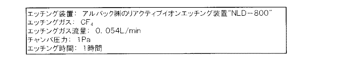
表1の“エッチングレートRe”欄には、単位面積の溶射皮膜に与えられるプラズマ出力(Pp)が1W/cm2(7.7×Pp2.2=7.7)、2W/cm2(7.7×Pp2.2=35.4)又は3W/cm2(7.7×Pp2.2=86.3)のCF4プラズマに各溶射皮膜を曝したときに、CF4プラズマによる溶射皮膜のエッチングレートを測定した結果を示す。具体的には、まず、平均粒子径0.06μmのコロイダルシリカを用いて各溶射皮膜の表面を鏡面研磨し、研磨後の溶射皮膜の表面の一部をポリイミドテープでマスキングしてから、その溶射皮膜の表面全体を表3に示す条件でプラズマエッチングした。その後、ケーエルエー・テンコール社の段差測定装置“アルファステップ”を用いて、マスキングした部分とマスキングしなかった部分の間の段差の大きさを測定した。 In the “etching rate Re” column of Table 1, the plasma power (Pp) applied to the thermal spray coating of the unit area is 1 W / cm 2 (7.7 × Pp 2.2 = 7.7), 2 W / cm 2 ( when exposed to the thermal spray coating to the CF 4 plasma 7.7 × Pp 2.2 = 35.4) or 3W / cm 2 (7.7 × Pp 2.2 = 86.3), by CF 4 plasma The result of having measured the etching rate of the thermal spray coating is shown. Specifically, first, the surface of each thermal spray coating is mirror-polished using colloidal silica having an average particle size of 0.06 μm, and a part of the surface of the thermal spray coating after polishing is masked with polyimide tape, and then the thermal spray is performed. The entire surface of the coating was plasma etched under the conditions shown in Table 3. Thereafter, the level difference between the masked portion and the unmasked portion was measured using a step measuring device “Alpha Step” manufactured by KLA-Tencor.
表1の“気孔率”欄には、各溶射皮膜の気孔率を測定した結果を示す。具体的には、まず、各溶射皮膜をその上面に直交する面で切断し、平均粒子径0.06μmのコロイダルシリカを用いてその切断面を鏡面研磨した。その後、エヌサポート社の画像解析処理装置“NSFJ1−A”を用いて、切断面で溶射皮膜の気孔率を測定した。 In the "Porosity" column of Table 1, the results of measuring the porosity of each thermal spray coating are shown. Specifically, first, each thermal spray coating was cut along a plane orthogonal to the upper surface, and the cut surface was mirror-polished using colloidal silica having an average particle diameter of 0.06 μm. Thereafter, the porosity of the sprayed coating was measured on the cut surface using an image analysis processing apparatus “NSFJ1-A” manufactured by NSupport.
表1の“膜厚”欄には、各溶射皮膜の厚さを測定した結果を示す。具体的には、まず、各溶射皮膜をその上面に直交する面で切断し、平均粒子径0.06μmのコロイダルシリカを用いてその切断面を鏡面研磨した。その後、光学顕微鏡を用いて、切断面で溶射皮膜の厚さを測定した。 In the “film thickness” column of Table 1, the results of measuring the thickness of each sprayed coating are shown. Specifically, first, each thermal spray coating was cut along a plane orthogonal to the upper surface, and the cut surface was mirror-polished using colloidal silica having an average particle diameter of 0.06 μm. Then, the thickness of the sprayed coating was measured on the cut surface using an optical microscope.
表1の“結晶子サイズ”欄には、各溶射皮膜中の結晶子のサイズを測定した結果を示す。具体的には、(株)リガク社製のX線回折装置“RINT−2000”を用いて測定される各溶射皮膜のX線回折パターンからHall法により結晶子のサイズを算出した。 The “crystallite size” column in Table 1 shows the results of measuring the crystallite size in each thermal spray coating. Specifically, the crystallite size was calculated by the Hall method from the X-ray diffraction pattern of each sprayed coating measured using an X-ray diffractometer “RINT-2000” manufactured by Rigaku Corporation.
表1の“ビッカース硬度”欄には、各溶射皮膜のビッカース微少硬度を測定した結果を示す。
表1の“摩耗比”欄には、往復運動平面摩耗試験(abrasive wheel wear test)による炭素鋼SS400の摩耗体積量に対する同じ往復運動平面摩耗試験による溶射皮膜の摩耗体積量の比率を測定した結果を示す。具体的には、往復運動平面摩耗試験では、JIS R6252に規定されたCP240番の研磨紙により荷重2.00kgf(約19.6N)で試料の表面を400回摩擦した。
The “Vickers hardness” column in Table 1 shows the results of measuring the Vickers microhardness of each sprayed coating.
In the “Wear ratio” column of Table 1, the result of measuring the ratio of the volume of wear of the thermal spray coating by the same reciprocating plane wear test to the volume of wear of the carbon steel SS400 by the reciprocating wheel wear test. Indicates. Specifically, in the reciprocating plane wear test, the surface of the sample was rubbed 400 times with a load of 2.00 kgf (about 19.6 N) using CP240 abrasive paper defined in JIS R6252.
表1の“溶射雰囲気”欄には、溶射皮膜を形成するべく各溶射用粉末をプラズマ溶射する際の雰囲気圧力を示す。
表1の”溶射用粉末の種類”欄には、各溶射用粉末がイットリア造粒粒子、イットリア造粒−焼結粒子及びイットリア溶融−粉砕粒子のいずれからなるものであるかを示す。
The “thermal spray atmosphere” column in Table 1 shows the atmospheric pressure when plasma spraying each thermal spray powder to form a thermal spray coating.
The “type of thermal spraying powder” column in Table 1 indicates whether each thermal spraying powder is composed of yttria granulated particles, yttria granulated-sintered particles, and yttria melted-pulverized particles.
表1の“溶射用粉末の平均粒子径”欄には、(株)堀場製作所のレーザー回折/散乱式粒度測定機“LA−300”を用いて測定した各溶射用粉末のイットリア造粒粒子、イットリア造粒−焼結粒子又はイットリア溶融−粉砕粒子の平均粒子径を示す。 In the “average particle diameter of thermal spraying powder” column of Table 1, yttria granulated particles of each thermal spraying powder measured using a laser diffraction / scattering particle size measuring device “LA-300” manufactured by Horiba, Ltd., The average particle diameter of yttria granulation-sintered particles or yttria melt-pulverized particles is shown.
表1の“造粒粒子又は造粒−焼結粒子を構成する一次粒子の平均粒子径”欄には、電界放射型走査電子顕微鏡(FE−SEM)を用いて測定した実施例1〜6,8〜11及び比較例1,2の各溶射用粉末のイットリア造粒粒子又はイットリア造粒−焼結粒子を構成する一次粒子の平均粒子径を示す。より具体的には、各溶射用粉末から10個のイットリア造粒粒子又はイットリア造粒−焼結粒子を任意に選択し、選択した10個のイットリア造粒粒子又はイットリア造粒−焼結粒子からそれぞれ50個の一次粒子を任意に選択し、各溶射用粉末につき合計500個の一次粒子について測定した定方向径(Feret径)の平均を示す。定方向径は、粒子をはさんで平行に延びる二本の仮想線の間の距離である。 In the column of “average particle diameter of primary particles constituting granulated particles or granulated-sintered particles” in Table 1, Examples 1 to 6 measured using a field emission scanning electron microscope (FE-SEM) The average particle diameter of the primary particle which comprises the yttria granulated particle or yttria granulated-sintered particle of each thermal spraying powder of 8-11 and Comparative Examples 1 and 2 is shown. More specifically, 10 yttria granulated particles or yttria granulated-sintered particles are arbitrarily selected from each thermal spraying powder, and 10 selected yttria granulated particles or yttria granulated-sintered particles are selected. Each of 50 primary particles is arbitrarily selected, and the average of the fixed direction diameter (Feret diameter) measured for a total of 500 primary particles for each thermal spraying powder is shown. The constant direction diameter is the distance between two imaginary lines extending in parallel across the particle.
Claims (5)
気孔率が12%以下であることを特徴とする溶射皮膜。 A thermal spray coating comprising as at least mainly of yttrium oxide, when the plasma power applied to the spray coating unit area were exposed sprayed coating to 0.8 W / cm 2 or more CF 4 plasma, by CF 4 plasma The etching rate of the thermal spray coating is the formula: Re ≦ 7.7 × Pp 2.2 (where Re represents the etching rate [nm / min] of the thermal spray coating by CF 4 plasma, and Pp is given to the thermal spray coating of the unit area. plasma power represents a [W / cm 2].) satisfied,
A thermal spray coating having a porosity of 12% or less .
Priority Applications (4)
| Application Number | Priority Date | Filing Date | Title |
|---|---|---|---|
| JP2005289174A JP4981293B2 (en) | 2005-09-30 | 2005-09-30 | Thermal spray coating |
| KR1020060096001A KR101333149B1 (en) | 2005-09-30 | 2006-09-29 | Thermal spray coating |
| TW095136128A TW200728503A (en) | 2005-09-30 | 2006-09-29 | Thermal spray coating |
| US11/540,011 US20070077456A1 (en) | 2005-09-30 | 2006-09-29 | Thermal spray coating |
Applications Claiming Priority (1)
| Application Number | Priority Date | Filing Date | Title |
|---|---|---|---|
| JP2005289174A JP4981293B2 (en) | 2005-09-30 | 2005-09-30 | Thermal spray coating |
Publications (2)
| Publication Number | Publication Date |
|---|---|
| JP2007100142A JP2007100142A (en) | 2007-04-19 |
| JP4981293B2 true JP4981293B2 (en) | 2012-07-18 |
Family
ID=38027369
Family Applications (1)
| Application Number | Title | Priority Date | Filing Date |
|---|---|---|---|
| JP2005289174A Expired - Lifetime JP4981293B2 (en) | 2005-09-30 | 2005-09-30 | Thermal spray coating |
Country Status (1)
| Country | Link |
|---|---|
| JP (1) | JP4981293B2 (en) |
Families Citing this family (1)
| Publication number | Priority date | Publication date | Assignee | Title |
|---|---|---|---|---|
| JP5154141B2 (en) * | 2007-05-21 | 2013-02-27 | 信越化学工業株式会社 | Rare earth oxide-containing thermal spray substrate and laminate |
Family Cites Families (9)
| Publication number | Priority date | Publication date | Assignee | Title |
|---|---|---|---|---|
| JP3510993B2 (en) * | 1999-12-10 | 2004-03-29 | トーカロ株式会社 | Plasma processing container inner member and method for manufacturing the same |
| JP3523216B2 (en) * | 2001-04-06 | 2004-04-26 | 信越化学工業株式会社 | Rare earth-containing compound particles for thermal spraying, thermal spraying member sprayed with the same |
| JP3672833B2 (en) * | 2000-06-29 | 2005-07-20 | 信越化学工業株式会社 | Thermal spray powder and thermal spray coating |
| JP2005097747A (en) * | 2000-06-29 | 2005-04-14 | Shin Etsu Chem Co Ltd | Thermal spray powder and thermal spray coating |
| JP4231990B2 (en) * | 2001-03-21 | 2009-03-04 | 信越化学工業株式会社 | Rare earth oxide spray particles and method for producing the same, thermal spray member and corrosion resistant member |
| JP2004332081A (en) * | 2003-05-12 | 2004-11-25 | Shin Etsu Chem Co Ltd | Plasma resistant member and method of manufacturing the same |
| JP2005060827A (en) * | 2003-07-29 | 2005-03-10 | Toshiba Ceramics Co Ltd | Plasma-resistant material |
| JP2005217349A (en) * | 2004-02-02 | 2005-08-11 | Toto Ltd | Member for semiconductor production system having plasma resistance and its production process |
| JP4051351B2 (en) * | 2004-03-12 | 2008-02-20 | トーカロ株式会社 | Y2O3 spray-coated member excellent in thermal radiation and damage resistance and method for producing the same |
-
2005
- 2005-09-30 JP JP2005289174A patent/JP4981293B2/en not_active Expired - Lifetime
Also Published As
| Publication number | Publication date |
|---|---|
| JP2007100142A (en) | 2007-04-19 |
Similar Documents
| Publication | Publication Date | Title |
|---|---|---|
| KR102702566B1 (en) | Yttrium fluoride sprayed coating, spray material therefor, and corrosion resistant coating including sprayed coating | |
| KR102282057B1 (en) | Sprayed coating, method for manufacturing sprayed coating, sprayed member and spraying material | |
| JP6117195B2 (en) | Parts for plasma processing apparatus and method for manufacturing parts for plasma processing apparatus | |
| KR20130120434A (en) | Thermal spraying powder and method for forming thermal spray coating | |
| TWI823980B (en) | Slurry for suspension plasma spraying, and method for forming sprayed coating | |
| CN116695048A (en) | Yttrium-based spray coating and method of manufacture | |
| JP4981291B2 (en) | Thermal spray powder and method of forming thermal spray coating | |
| TWI375734B (en) | Ceramic coating material for thermal spray on the parts of semiconductor processing devices and fabrication method and coating method thereof | |
| KR101284474B1 (en) | Semiconductor fabrication device component and semiconductor fabrication device | |
| WO2015080134A1 (en) | Plasma device part and manufacturing method therefor | |
| CN115261762A (en) | Material for thermal spraying | |
| JP2017061738A (en) | Thermal spray material | |
| JP4981294B2 (en) | Thermal spray coating | |
| JP4981293B2 (en) | Thermal spray coating | |
| JP2007126712A (en) | Powder for thermal spraying and method for forming thermally sprayed coating | |
| JP4981292B2 (en) | Thermal spray powder and method of forming thermal spray coating | |
| KR101333149B1 (en) | Thermal spray coating | |
| JP4630799B2 (en) | Thermal spray powder and method of forming thermal spray coating | |
| KR20240111598A (en) | The method of producing thermal spray coating and the yittrium coating produced by the method | |
| JP2007126711A (en) | Powder for thermal spraying and method for forming thermally sprayed coating | |
| WO2015080135A1 (en) | Plasma device part and manufacturing method therefor |
Legal Events
| Date | Code | Title | Description |
|---|---|---|---|
| A621 | Written request for application examination |
Free format text: JAPANESE INTERMEDIATE CODE: A621 Effective date: 20080901 |
|
| A977 | Report on retrieval |
Free format text: JAPANESE INTERMEDIATE CODE: A971007 Effective date: 20110928 |
|
| A131 | Notification of reasons for refusal |
Free format text: JAPANESE INTERMEDIATE CODE: A131 Effective date: 20111004 |
|
| A521 | Request for written amendment filed |
Free format text: JAPANESE INTERMEDIATE CODE: A523 Effective date: 20111202 |
|
| TRDD | Decision of grant or rejection written | ||
| A01 | Written decision to grant a patent or to grant a registration (utility model) |
Free format text: JAPANESE INTERMEDIATE CODE: A01 Effective date: 20120327 |
|
| A01 | Written decision to grant a patent or to grant a registration (utility model) |
Free format text: JAPANESE INTERMEDIATE CODE: A01 |
|
| A61 | First payment of annual fees (during grant procedure) |
Free format text: JAPANESE INTERMEDIATE CODE: A61 Effective date: 20120420 |
|
| FPAY | Renewal fee payment (event date is renewal date of database) |
Free format text: PAYMENT UNTIL: 20150427 Year of fee payment: 3 |
|
| R150 | Certificate of patent or registration of utility model |
Free format text: JAPANESE INTERMEDIATE CODE: R150 Ref document number: 4981293 Country of ref document: JP Free format text: JAPANESE INTERMEDIATE CODE: R150 |
|
| R250 | Receipt of annual fees |
Free format text: JAPANESE INTERMEDIATE CODE: R250 |
|
| R250 | Receipt of annual fees |
Free format text: JAPANESE INTERMEDIATE CODE: R250 |
|
| R250 | Receipt of annual fees |
Free format text: JAPANESE INTERMEDIATE CODE: R250 |
|
| R250 | Receipt of annual fees |
Free format text: JAPANESE INTERMEDIATE CODE: R250 |
|
| R250 | Receipt of annual fees |
Free format text: JAPANESE INTERMEDIATE CODE: R250 |
|
| R250 | Receipt of annual fees |
Free format text: JAPANESE INTERMEDIATE CODE: R250 |
|
| R250 | Receipt of annual fees |
Free format text: JAPANESE INTERMEDIATE CODE: R250 |
|
| R250 | Receipt of annual fees |
Free format text: JAPANESE INTERMEDIATE CODE: R250 |
|
| R250 | Receipt of annual fees |
Free format text: JAPANESE INTERMEDIATE CODE: R250 |
|
| R250 | Receipt of annual fees |
Free format text: JAPANESE INTERMEDIATE CODE: R250 |
|
| R250 | Receipt of annual fees |
Free format text: JAPANESE INTERMEDIATE CODE: R250 |
|
| EXPY | Cancellation because of completion of term |