JP4979271B2 - ENDOSCOPE SYSTEM AND ENDOSCOPE OPERATING METHOD - Google Patents
ENDOSCOPE SYSTEM AND ENDOSCOPE OPERATING METHOD Download PDFInfo
- Publication number
- JP4979271B2 JP4979271B2 JP2006148039A JP2006148039A JP4979271B2 JP 4979271 B2 JP4979271 B2 JP 4979271B2 JP 2006148039 A JP2006148039 A JP 2006148039A JP 2006148039 A JP2006148039 A JP 2006148039A JP 4979271 B2 JP4979271 B2 JP 4979271B2
- Authority
- JP
- Japan
- Prior art keywords
- image
- speed
- insertion portion
- light
- frame rate
- Prior art date
- Legal status (The legal status is an assumption and is not a legal conclusion. Google has not performed a legal analysis and makes no representation as to the accuracy of the status listed.)
- Expired - Fee Related
Links
- 238000011017 operating method Methods 0.000 title claims description 3
- 238000003780 insertion Methods 0.000 claims description 158
- 230000037431 insertion Effects 0.000 claims description 158
- 238000001514 detection method Methods 0.000 claims description 36
- 238000003384 imaging method Methods 0.000 claims description 24
- 230000035945 sensitivity Effects 0.000 claims description 22
- 230000003287 optical effect Effects 0.000 claims description 16
- 238000012937 correction Methods 0.000 claims description 9
- 238000001727 in vivo Methods 0.000 claims description 5
- 238000000034 method Methods 0.000 claims description 5
- 238000012545 processing Methods 0.000 description 9
- 238000002073 fluorescence micrograph Methods 0.000 description 4
- 230000003902 lesion Effects 0.000 description 4
- 238000010586 diagram Methods 0.000 description 3
- 230000007423 decrease Effects 0.000 description 2
- 230000005284 excitation Effects 0.000 description 2
- 238000012986 modification Methods 0.000 description 2
- 230000004048 modification Effects 0.000 description 2
- 239000000126 substance Substances 0.000 description 2
- 206010061218 Inflammation Diseases 0.000 description 1
- 206010028980 Neoplasm Diseases 0.000 description 1
- 206010034960 Photophobia Diseases 0.000 description 1
- 206010034972 Photosensitivity reaction Diseases 0.000 description 1
- 201000011510 cancer Diseases 0.000 description 1
- 238000006243 chemical reaction Methods 0.000 description 1
- 230000003247 decreasing effect Effects 0.000 description 1
- 229910052736 halogen Inorganic materials 0.000 description 1
- 150000002367 halogens Chemical class 0.000 description 1
- 230000004054 inflammatory process Effects 0.000 description 1
- 230000001678 irradiating effect Effects 0.000 description 1
- 208000013469 light sensitivity Diseases 0.000 description 1
- 239000013307 optical fiber Substances 0.000 description 1
- 230000036211 photosensitivity Effects 0.000 description 1
- 230000000644 propagated effect Effects 0.000 description 1
- 229910052724 xenon Inorganic materials 0.000 description 1
- FHNFHKCVQCLJFQ-UHFFFAOYSA-N xenon atom Chemical compound [Xe] FHNFHKCVQCLJFQ-UHFFFAOYSA-N 0.000 description 1
Images


Classifications
-
- A—HUMAN NECESSITIES
- A61—MEDICAL OR VETERINARY SCIENCE; HYGIENE
- A61B—DIAGNOSIS; SURGERY; IDENTIFICATION
- A61B1/00—Instruments for performing medical examinations of the interior of cavities or tubes of the body by visual or photographical inspection, e.g. endoscopes; Illuminating arrangements therefor
- A61B1/04—Instruments for performing medical examinations of the interior of cavities or tubes of the body by visual or photographical inspection, e.g. endoscopes; Illuminating arrangements therefor combined with photographic or television appliances
Landscapes
- Health & Medical Sciences (AREA)
- Life Sciences & Earth Sciences (AREA)
- Surgery (AREA)
- Biomedical Technology (AREA)
- Medical Informatics (AREA)
- Optics & Photonics (AREA)
- Pathology (AREA)
- Radiology & Medical Imaging (AREA)
- Biophysics (AREA)
- Engineering & Computer Science (AREA)
- Physics & Mathematics (AREA)
- Heart & Thoracic Surgery (AREA)
- Nuclear Medicine, Radiotherapy & Molecular Imaging (AREA)
- Molecular Biology (AREA)
- Animal Behavior & Ethology (AREA)
- General Health & Medical Sciences (AREA)
- Public Health (AREA)
- Veterinary Medicine (AREA)
- Endoscopes (AREA)
- Closed-Circuit Television Systems (AREA)
- Instruments For Viewing The Inside Of Hollow Bodies (AREA)
Description
この発明は、内視鏡システムおよび内視鏡観察方法に関するものである。 The present invention relates to an endoscope system and an endoscope observation method.
従来、内視鏡システムにおいて、生体の体腔内に挿入される挿入部の先端位置を正確に検出するために、挿入部の外面に、挿入部の先端からの距離を示すマークを設け、これを読み取り装置により読み取る技術が知られている(例えば、特許文献1および特許文献2参照。)
ところで、挿入方向に交差する方向の画像を取得する側視観察の場合には、挿入部の外径寸法が限られているために、1回に取得される画像は挿入部の挿入方向に沿って極めて微小の幅寸法の短冊状の画像となる。このため、挿入部の挿入方向に連続した所望の範囲の画像を取得するには、1回に取得される短冊状の画像の幅寸法分だけ送りをかけながら撮影を繰り返すことが必要となる。 By the way, in the case of side-view observation in which an image in the direction intersecting the insertion direction is acquired, the outer diameter size of the insertion portion is limited, so the image acquired at one time is along the insertion direction of the insertion portion. It becomes a strip-like image with extremely small width dimensions. For this reason, in order to acquire the image of the desired range continuous in the insertion direction of the insertion part, it is necessary to repeat imaging while feeding by the width dimension of the strip-shaped image acquired at one time.
しかしながら、内視鏡の挿入部は通常、操作者のマニュアル操作により生体内に挿入されるため、送り量および挿入速度は一定せず、速く挿入した場合には、得られる画像が細切れとなって、患部の画像を取得することができない場合があるという問題がある。
本発明は、上述した事情に鑑みてなされたものであって、患部の見落としを防止することができる内視鏡システムおよび内視鏡観察方法を提供することを目的としている。
However, since the insertion portion of the endoscope is normally inserted into the living body by an operator's manual operation, the feed amount and the insertion speed are not constant. There is a problem that an image of the affected part may not be acquired.
The present invention has been made in view of the above-described circumstances, and an object thereof is to provide an endoscope system and an endoscope observation method capable of preventing an oversight of an affected area.
上記目的を達成するために、本発明は以下の手段を提供する。
本発明は、生体に照射される照射光を発する光源と、生体に挿入され、前記光源からの照射光および生体からの戻り光を導光する挿入部と、該挿入部先端に設けられ、前記挿入部を介して導光された前記照射光を前記挿入部の半径方向外方に指向させ、生体からの前記挿入部の半径方向内方に向かう戻り光を挿入部内に導入する偏向光学系と、前記挿入部を介して導光された戻り光を撮影する撮像手段と、前記挿入部の挿入速度を検出する挿入速度検出手段と、該挿入速度検出手段により検出された挿入速度に応じて前記撮像手段により撮影するフレームレートを調節するフレームレート調節手段と、前記挿入速度検出手段により検出された挿入速度に基づいて、前記撮像手段による露光時間を補正する露光補正手段と、該露光補正手段により補正された露光時間に応じて撮像手段の受光感度を補正する感度補正手段と、前記撮像手段により得られた短冊状の画像を前記挿入速度に基づくピッチで配列し、生体内の画像を形成する画像形成手段と、該画像形成手段により形成された画像を表示する表示手段とを備える内視鏡システムを提供する。
In order to achieve the above object, the present invention provides the following means.
The present invention is provided with a light source that emits irradiation light applied to a living body, an insertion part that is inserted into the living body and guides irradiation light from the light source and return light from the living body, and a tip of the insertion part, A deflecting optical system for directing the irradiation light guided through the insertion portion radially outward of the insertion portion and introducing return light from the living body toward the radial inward of the insertion portion into the insertion portion; Imaging means for photographing the return light guided through the insertion section, insertion speed detection means for detecting the insertion speed of the insertion section, and the insertion speed detected by the insertion speed detection means according to the insertion speed A frame rate adjusting means for adjusting a frame rate to be photographed by the imaging means; an exposure correcting means for correcting an exposure time by the imaging means based on the insertion speed detected by the insertion speed detecting means; and Yo Arranged in the sensitivity correction means for correcting the light receiving sensitivity of the imaging means, the pitch-based strip-shaped image obtained by the imaging means to the insertion speed in response to the corrected exposure time to form an image in vivo An endoscope system including an image forming unit and a display unit that displays an image formed by the image forming unit is provided.
本発明によれば、挿入部を生体内に挿入した状態で、光源から発せられた照射光が偏向光学系により挿入部の半径方向外方に配されている生体に照射され、生体からの戻り光が偏向光学系により挿入部内に導入され、挿入部を介して撮像手段により撮影されることで、挿入部の先端位置に対応した位置の細い短冊状の画像が取得される。また、挿入部が挿入されると挿入速度検出手段の作動により挿入部の挿入速度が検出され、フレームレート調節手段の作動により、撮像手段によって撮像される際のフレームレートが調節される。 According to the present invention, in a state where the insertion portion is inserted into the living body, the irradiation light emitted from the light source is irradiated to the living body arranged radially outward of the insertion portion by the deflection optical system, and the return from the living body is performed. Light is introduced into the insertion portion by the deflecting optical system and photographed by the imaging means through the insertion portion, whereby a thin strip-like image at a position corresponding to the tip position of the insertion portion is acquired. Further, when the insertion section is inserted, the insertion speed of the insertion section is detected by the operation of the insertion speed detection means, and the frame rate at the time of imaging by the imaging means is adjusted by the operation of the frame rate adjustment means.
すなわち、挿入部が速く挿入される際にはフレームレートを高く調節することにより、高い頻度で短冊状の画像を取得し、遅く挿入される際にはフレームレートを低く調節して、低い頻度で短冊状の画像を取得する。そして、画像形成手段の作動により、撮像手段によって得られた短冊状の画像を挿入速度に基づくピッチで配列することにより、抜けのない連続した生体内の画像を形成することができ、形成された画像を表示手段により表示することで、患部の見落としをより確実に防止することができる。 That is, when the insertion unit is inserted quickly, the frame rate is adjusted to be high, thereby obtaining a strip-like image with high frequency.When the insertion unit is inserted slowly, the frame rate is adjusted to be low, and the frame rate is adjusted with low frequency. Get a strip-shaped image. Then, by operating the image forming means, the strip-like images obtained by the imaging means are arranged at a pitch based on the insertion speed, so that a continuous in-vivo image without omission can be formed and formed. By displaying the image by the display means, it is possible to more reliably prevent the affected part from being overlooked.
また、露光補正手段の作動により、挿入部の挿入速度に応じて撮像手段による露光時間が補正されるので、速く挿入される際には露光時間を短くして画像のブレを防止し鮮明な画像を取得することができる。さらに、感度補正手段の作動により、露光時間に応じて撮像手段の受光感度が補正されるので、露光時間が短くなる場合には受光感度を高めて、画像が暗くなるのを防止することができる。その結果、生体から戻る蛍光の輝度情報によって病変の大きさや進行度を定量化する分子イメージング方法の場合、定量性を損なうことなく、鮮明な連続した画像を取得することができる。 In addition, since the exposure time is corrected by the imaging unit according to the insertion speed of the insertion portion by the operation of the exposure correction unit, the exposure time is shortened to prevent blurring of the image when inserted quickly. Can be obtained. Furthermore, since the light receiving sensitivity of the image pickup means is corrected according to the exposure time by the operation of the sensitivity correcting means, when the exposure time is shortened, the light receiving sensitivity can be increased to prevent the image from becoming dark. . As a result, in the case of a molecular imaging method that quantifies the size and progress of a lesion based on the luminance information of fluorescence returning from a living body, a clear continuous image can be acquired without impairing the quantitativeness.
また、上記発明においては、前記挿入速度検出手段が、前記挿入部の外面に挿入方向に沿って設けられたマークと、該マークを検出するマーク検出手段と、検出されたマークに基づいて挿入速度を算出する速度算出手段とを備えることとしてもよい。
マーク検出手段により検出された挿入部外面のマークに基づいて、速度算出手段の作動により挿入部の速度が算出される。これにより、簡易に挿入部の速度を検出でき、撮像手段による撮影のフレームレート、あるいは、露光時間および受光感度を適正な値に設定することが可能となる。
Further, in the above invention, the insertion speed detection means includes a mark provided on the outer surface of the insertion portion along the insertion direction, a mark detection means for detecting the mark, and an insertion speed based on the detected mark. It is good also as providing the speed calculation means which calculates.
Based on the mark on the outer surface of the insertion portion detected by the mark detection means, the speed of the insertion portion is calculated by the operation of the speed calculation means. Thereby, the speed of the insertion portion can be easily detected, and the frame rate of photographing by the imaging means, or the exposure time and the light receiving sensitivity can be set to appropriate values.
また、上記発明においては、前記戻り光が、蛍光または白色光の少なくとも1つを含むこととしてもよい。
また、上記発明においては、前記偏向光学系が、円錐ミラーを含むこととしてもよい。
In the above invention, the return light may include at least one of fluorescence and white light.
In the above invention, the deflecting optical system may include a conical mirror.
また、本発明は、生体に挿入される挿入部の先端から、挿入方向の各位置において半径方向外方に向けて照射光を発生し、生体から戻る戻り光を撮影して短冊状の画像を取得し、取得された画像を配列して生体内の画像を形成し、生成された画像を表示する内視鏡の作動方法であって、挿入速度検出手段が挿入部の挿入速度を検出し、検出された前記挿入速度に基づいて、フレームレート調節手段が短冊状の画像を取得するフレームレートを調節し、検出された前記挿入速度に基づいて、露光補正手段が短冊状の画像を取得する際の露光時間を補正し、感度補正手段が、補正された露光時間に応じて受光感度を補正する内視鏡の作動方法を提供する。 Further, the present invention generates irradiation light from the distal end of the insertion portion to be inserted into the living body toward the outside in the radial direction at each position in the insertion direction, and captures the return light returning from the living body to form a strip-shaped image. It is an operation method of an endoscope that forms an in-vivo image by arranging the acquired images and displays the generated image, and an insertion speed detection unit detects the insertion speed of the insertion unit, When the frame rate adjusting means adjusts the frame rate for acquiring the strip-shaped image based on the detected insertion speed, and the exposure correcting means acquires the strip-shaped image based on the detected insertion speed. and the corrected exposure time, sensitivity correction means, that provides an operating method of an endoscope for correcting the light receiving sensitivity in accordance with the corrected exposure time.
本発明によれば、挿入速度にかかわらず、挿入方向に連続した鮮明な画像を取得することを可能として、患部の見落としを防止することができるという効果を奏する。 According to the present invention, it is possible to acquire a clear image continuous in the insertion direction regardless of the insertion speed, and it is possible to prevent the affected part from being overlooked.
本発明の第1の実施形態に係る内視鏡システム1について、図1〜図11を参照して以下に説明する。
本実施形態に係る内視鏡観察装置1は、図1に示されるように、光源2と、該光源2に接続され体腔内に挿入される細長い挿入部3と、該挿入部3に接続され、被検体である生体組織から戻る戻り光を検出する光検出部4と、前記挿入部3の移動速度を検出する速度検出部5と、該速度検出部5により検出された移動速度に基づいて、光検出部4を制御する制御部6と、前記光検出部4により検出された画像情報および速度検出部5において検出された移動速度に基づいて生体組織の画像を形成する画像処理部7と、該画像処理部7において生成された生体組織の画像を表示する画像表示部8とを備えている。
An
As shown in FIG. 1, an
前記光源2は、例えば、キセノンランプ、ハロゲンランプ等、白色光および励起光のような広帯域の光を発するものが採用されている。
前記挿入部3は、前記光源2からの光を該挿入部3の先端まで導くライトガイド(あるいは光ファイバ束)9と、挿入部3の先端に配置され、ライトガイド9内を伝播されてきた光を半径方向外方に向けて放射状に偏向するとともに、生体組織から挿入部3の半径方向内方に向かう戻り光を挿入部3内に導入する円錐ミラー(偏向光学系)10と、該円錐ミラー10により導入された戻り光を挿入部3の後端側へ導くイメージガイド17と、円錐ミラー10とイメージガイド17との間に配置され、生体組織の像をイメージガイド17の先端面に結像する結像光学系18と、ライトガイド9を被覆するアウターチューブ11とを備えている。
挿入部3の後端には、生体組織において反射して戻る白色光と、生体組織に励起光が照射されることにより、生体組織内の蛍光物質が励起されて発生する蛍光とを分岐するダイクロイックプリズム12が設けられている。
As the
The
A dichroic that branches white light reflected back from the living tissue and fluorescence generated when the fluorescent substance in the living tissue is excited by irradiating the living tissue with excitation light at the rear end of the
前記光検出部4は、ダイクロイックプリズム12により分岐された白色光を検出する白色光検出器13と、蛍光を検出する蛍光検出器14とを備えている。
前記速度検出部5は、前記アウターチューブ11の外面に、長手方向に間隔をあけて複数設けられたマーク15と、該マーク15を撮影する画像センサ16とを備えている。
The light detection unit 4 includes a
The
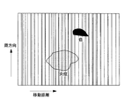
アウターチューブ11に設けられるマーク15としては、例えば、図2および図3に示されるように、挿入方向に一定間隔で設けられた太さの異なる帯状のマーク15が挙げられる。図2および図3に示されるように、画像センサ16の長方形の注目領域Sの左端を基準位置S0として、該基準位置S0と、該基準位置S0に最も近いマーク15のエッジS1との距離L1、および、該エッジS1とそれに隣接するエッジS2との距離L2に基づいて、挿入部3の挿入距離を検出することができるようになっている。
As the
例えば、図2に示されるように、画像センサ16の注目領域S内に単一のマーク15のみが配置されているときには、注目領域Sの基準位置S0と該基準位置S0に最も近い左側エッジS1との距離L1と、マーク15の幅寸法L2とにより基づいて、挿入部3の移動距離を算出することができる。マーク15の幅寸法L2は各マーク15に固有であるため、挿入部3先端からの当該マーク15の位置は既知であり、そのマーク15のエッジS1から画像センサ16の基準位置S0までの距離L1を知ることで、挿入部3の移動距離を算出することができる。
For example, as shown in FIG. 2, when only a
また、例えば、図3に示されるように、画像センサ16の注目領域S内に2つのマーク15が配置されているときには、注目領域Sの基準位置S0と該基準位置S0に最も近い右側エッジS1との距離L1と、2つのマーク15の間隔寸法L2とに基づいて、挿入部3の移動距離を算出できる。2つのマーク15の間隔寸法L2は、当該マーク15に固有であるため、挿入部3先端からの当該マーク15の位置は既知であり、そのマーク15のエッジS1から画像センサ16の基準位置S0までの距離L1を知ることで、挿入部3の移動距離を算出できるようになっている。
Further, for example, as shown in FIG. 3, when the two marks 15 in the attention area S of the
さらに、2つの時刻において算出された移動距離の差をその時刻間の時間によって除算することにより、挿入部3の挿入速度を算出することができる。
前記制御部6は、上記挿入部3の移動距離および挿入速度の演算を行うとともに、算出された挿入速度に基づいて、白色光検出器13および蛍光検出器14のフレームレートを調節するようになっている。例えば、挿入速度が速くなるとフレームレートを高くするように調節し、挿入速度が遅くなるとフレームレートを低くするように調節する。
Furthermore, the insertion speed of the
The
また、制御部6は、挿入部3の挿入速度が速くなると、白色光検出器13および蛍光検出器14の露光時間および受光感度を補正するようになっている。挿入速度vと露光時間tとの関係を図4に示す。また、露光時間tと受光感度sとの関係を図5に示す。これらの図4,図5に基づいて、挿入速度vと受光感度sとの関係は図6に示す通りとなる。これらの図によれば、制御部6は、挿入速度vが速くなると露光時間tを短くし、受光感度sを上げるように補正し、挿入速度vが遅くなると露光時間tを長くし、受光感度sを下げる補正を行うようになっている。
Further, the
前記画像処理部7は、挿入部3先端の位置毎に、光検出器13,14により取得された短冊状の画像を所定のピッチで配列することにより、2次元的な画像を形成するようになっている。短冊状の画像は、挿入部3の挿入速度vおよび該挿入速度vにより設定されたフレームレートfに基づいて挿入方向の単位長さ当たりに所定の枚数だけ取得されるので、それらの画像を挿入速度vとフレームレートfに基づいて定まる所定のピッチで配列することにより、2次元的な画像を生成することができるようになっている。
The
画像表示部8は、例えば、白色光検出器13により検出され、画像処理部7により処理された2次元的な白色光画像G1、蛍光検出器14により検出され、画像処理部7により処理された2次元的な蛍光画像G2および挿入部3の挿入方向に沿う蛍光画像G2の輝度分布G3を表示するようになっている。
The
このように構成された本実施形態に係る内視鏡システム1の作用について以下に説明する。
本実施形態に係る内視鏡システム1を用いて、生体の体腔内の様子を観察するには、挿入部3を体腔内に挿入し、光源2からの光をライトガイド9を介して挿入部3の先端に導き、円錐ミラー10によって半径方向外方に偏向し、放射状に照射させる。挿入部3先端の半径方向外方に配置された体腔の内壁において反射して戻る白色光および体腔内壁内の蛍光物質を励起して発生した蛍光が、円錐ミラー10および結像光学系18を介してイメージガイド17内に戻り、イメージガイド17を伝播してダイクロイックプリズム12により分岐され、それぞれ白色光検出器13および蛍光検出器14により検出される。
The operation of the
In order to observe the state of the living body inside the body cavity using the
制御部6により設定された各検出器13,14の1フレーム当たりの露光時間t内に取得される画像は、円錐ミラー10の寸法により幾何学的に決定される幅寸法の短冊状の画像であって、挿入部3の軸線周りに周方向にほぼ全周にわたって取得される。各画像は、円錐ミラーの円錐状の反射面により極座標変換されているので、画像処理部7において平面座標に変換され直される。
An image acquired within the exposure time t per frame of each
また、挿入部3が移動させられると、速度検出部5の作動により、画像センサ16による検出信号に基づいて、制御部6において挿入速度vが算出される。制御部6においては、移動速度vに応じてフレームレートf、露光時間tおよび受光感度sが算出され、各検出器13,14に対して指令信号が出力される。
When the
ここで、例えば、図7に示されるように、移動速度vに対して段階的にフレームレートfを変更する場合について説明する。1フレーム毎に得られる短冊状の画像の幅寸法が0.2mmであるとすると、例えば、移動速度vが、0<v≦6(mm/s)の場合に、フレームレートf=30(1/s)、6<v≦12(mm/s)の場合に、f=60(1/s)、12<v≦24(mm/s)の場合に、f=120(1/s)に設定する。これは、挿入部3がそれぞれの移動速度vの範囲の最大値で移動する場合に、隣接する短冊状の画像間に隙間が形成されないように取得するためのフレームレートfとなっている。
Here, for example, as shown in FIG. 7, a case where the frame rate f is changed stepwise with respect to the moving speed v will be described. Assuming that the width of the strip-shaped image obtained for each frame is 0.2 mm, for example, when the moving speed v is 0 <v ≦ 6 (mm / s), the frame rate f = 30 (1 / S), 6 <v ≦ 12 (mm / s), f = 60 (1 / s), 12 <v ≦ 24 (mm / s), f = 120 (1 / s) Set. This is a frame rate f for obtaining the
具体的には、図8に鎖線で示されるように移動速度vが変化する場合に、実線で示されるようにフレームレートfを変化させる。そして、得られた短冊状の画像を挿入部3の移動距離に対応させて配列することにより、図9に示されるように、移動速度vに対して十分に高いフレームレートfを有する場合には、隣接する短冊状の画像どうしが重なるように配列され、画像間に隙間が生じないように配列された2次元的な白色光画像G1および蛍光画像G2を取得することが可能となる。
Specifically, when the moving speed v changes as indicated by a chain line in FIG. 8, the frame rate f is changed as indicated by a solid line. Then, by arranging the obtained strip-shaped images in correspondence with the moving distance of the
したがって、画像処理部7により形成された画像G1,G2には隙間がなく、これを画像表示部8に表示することにより、挿入方向に沿う生体組織の画像を漏れなく表示することができる。その結果、観察者が患部を見落とすことをより確実に防止することができるという利点がある。
Therefore, there is no gap between the images G1 and G2 formed by the
また、本実施形態によれば、挿入部の移動速度の変化にかかわらず、図10に示されるように、挿入部3の挿入方向に歪んでいない画像を取得することができる。そして、例えば、図11に示されるように、移動距離と周方向の蛍光強度の総和との関係を示すグラフを描くことにより、高い蛍光強度を示す位置に、癌細胞や炎症等の病変の存在を確認することができる。
Further, according to the present embodiment, an image that is not distorted in the insertion direction of the
この場合において、本実施形態によれば、挿入速度vに応じて露光時間tを調節することで、速い挿入速度vで挿入される場合に露光時間tを短くしてブレを防止することができる。また、露光時間tのみを短くすると蛍光画像の強度が変化することとなるが、本実施形態に置いては露光時間tに対応させて受光感度sを調節しているので、蛍光画像の強度を変化させることが防止され、病変を確認するための蛍光強度の定量性を確保することができるという利点がある。 In this case, according to the present embodiment, by adjusting the exposure time t according to the insertion speed v, the exposure time t can be shortened to prevent blurring when inserted at a high insertion speed v. . Further, when only the exposure time t is shortened, the intensity of the fluorescent image changes. However, in the present embodiment, the light reception sensitivity s is adjusted corresponding to the exposure time t. There is an advantage that it is possible to prevent the change and to secure the quantitativeness of the fluorescence intensity for confirming the lesion.
なお、本実施形態に係る内視鏡システム1において、図12に示されるように、挿入部3は、白色光検出器13および蛍光検出器14に対して着脱可能に構成されることとしてもよい。すなわち、白色光検出器13,蛍光検出器14およびダイクロイックプリズム12を含む光検出装置19に、光コネクタ20を介して挿入部3を着脱させることとすればよい。
In the
この場合において、光検出装置19には、光コネクタ20を接続するレセプタクル21と、該レセプタクル21とダイクロイックプリズム12とを接続する第2のイメージガイド22と、後述する情報保持部23内に保持されている情報を読み取る情報検知部24とが備えられている。
また、光コネクタ20は、レセプタクル21に接続されたときに第2のイメージガイド22の端面に対向させるようにイメージガイド17を保持しているとともに、前記情報検知部24に対向する位置に配される情報保持部23を備えている。
In this case, the
The
情報保持部23は、偏向光学系に関する特徴情報として、挿入部3先端に配されている円錐ミラー10の形状により規定される1フレーム毎の短冊状の画像の幅寸法に係る情報を保持している。
具体的には、情報検知部24は、例えば、図13に示されるように、複数の押しピン24aと該押しピン24aに接続されたスイッチ24bとを備えている。また、情報保持部23は、複数の押しピン24aの内の一部の押しピン24aに対応する位置に配置された複数の検知ピン23aを備えている。
The
Specifically, for example, as illustrated in FIG. 13, the
ここで、複数の検知ピン23aは、円錐ミラー10の形状により規定される1フレーム毎の短冊状の画像の幅寸法に応じて、各挿入部3毎に異なる配列となるように設定されている。すなわち、検知ピン23aの配列が、短冊状の画像の幅寸法に係る情報を保持している。
Here, the plurality of detection pins 23 a are set so as to be arranged differently for each
スイッチ24bは、押しピン24aが押されるときにオンの状態となるように構成されている。つまり、検知ピン23aに対向した一部の押しピン24aのみが検知ピン23aにより押され、該押しピン24aに接続されているスイッチ24bのみが選択的に導通されるようになっている。
The
これにより、情報検知部24は、複数の信号線24cの一部を選択的に導通させられることにより、短冊状の画像の幅寸法に係る情報を検知して、当該信号線24cにより伝送される信号束を検知信号として制御部6に出力するようになっている。
制御部6においては、情報検知部24から入力された検知信号に基づいて、短冊状の画像の幅寸法を読み取り、移動速度vに応じたフレームレートfの算出の設定が変更され、変更後の設定に基づいて移動速度vに応じてフレームレートf、露光時間tおよび受光感度sが算出され、各検出器13,14に対して指令信号が出力されるようになっている。
Thereby, the
In the
この場合に、挿入部3が交換されると、該挿入部3の先端に設けられている円錐ミラー10の視野範囲、すなわち、1フレーム毎の短冊状の画像の幅寸法に比例して移動速度vの範囲が設定される。例えば、上記画像の幅寸法が0.5mmである場合に、移動速度vが0<v≦15mm/sではフレームレート30(1/s)、移動速度15<v≦30mm/sではフレームレート60(1/s)、移動速度30<v≦60mm/sではフレームレート120(1/s)に設定される。つまり、上記画像の幅寸法が広い程、移動速度を速くすることができる。
In this case, when the
このように構成することにより、短冊状の画像の幅寸法の変化に応じて、適切なフレームレートfを設定でき、円錐ミラー10等の偏向光学系の形状が異なるような挿入部3に交換する場合であっても、画像間に隙間が生じないように配列された2次元的な白色光画像G1および蛍光画像G2を取得することができる。また、この場合に、隣接する短冊状の画像どうしの重なりを必要かつ最小限に抑えることができる。その結果、画像処理量を最適化するとともに、観察者が患部を見落としてしまうことをより確実に防止することができる。
With this configuration, an appropriate frame rate f can be set in accordance with a change in the width of the strip-shaped image, and the
また、本実施形態においては、挿入方向に間隔をあけたマークの幅寸法が変化する場合について説明したが、図14に示されるように等間隔の縞状のマークを採用し、マークの数をカウントすることで、移動距離を検出することとしてもよい。
また、画像表示部においては、図15に示されるように、挿入部の移動距離を表示することとしてもよい。
In the present embodiment, the case where the width dimension of the marks spaced in the insertion direction changes has been described. However, as shown in FIG. The movement distance may be detected by counting.
Further, in the image display unit, as shown in FIG. 15, the moving distance of the insertion unit may be displayed.
さらに、図16に示されるように、挿入部の移動距離の表示に併せて、輝度の総和値の高い部分を指示する表示を行うこととしてもよい。これにより、輝度値が高く、病変の可能性が高い部分において挿入部をゆっくり移動させ、詳細な観察を行うとともに、それ以外の部分においては速く移動させて観察効率を向上することができる。 Furthermore, as shown in FIG. 16, in addition to the display of the movement distance of the insertion unit, a display indicating a portion having a high luminance sum may be performed. Accordingly, the insertion portion can be moved slowly in a portion where the luminance value is high and the possibility of a lesion is high, and detailed observation can be performed, and in other portions, the observation portion can be moved quickly to improve observation efficiency.
f フレームレート
s 受光感度
t 露光時間
1 内視鏡システム
2 光源
3 挿入部
4 光検出器(撮像手段)
5 速度検出部(挿入速度検出手段)
6 制御部(フレームレート調節手段:露光補正手段:感度補正手段:速度算出手段)
7 画像処理部(画像形成手段)
8 画像表示部(表示手段)
10 円錐ミラー(偏向光学系)
13 白色光検出器(撮像手段)
14 蛍光検出器(撮像手段)
15 マーク
16 画像センサ(マーク検出手段)
f Frame rate s Photosensitivity
5 Speed detector (insertion speed detector)
6 Control unit (frame rate adjusting means: exposure correcting means: sensitivity correcting means: speed calculating means)
7 Image processing unit (image forming means)
8 Image display (display means)
10 Conical mirror (deflection optical system)
13 White light detector (imaging means)
14 Fluorescence detector (imaging means)
15
Claims (5)
生体に挿入され、前記光源からの照射光および生体からの戻り光を導光する挿入部と、
該挿入部先端に設けられ、前記挿入部を介して導光された前記照射光を前記挿入部の半径方向外方に指向させ、生体からの前記挿入部の半径方向内方に向かう戻り光を挿入部内に導入する偏向光学系と、
前記挿入部を介して導光された戻り光を撮影する撮像手段と、
前記挿入部の挿入速度を検出する挿入速度検出手段と、
該挿入速度検出手段により検出された挿入速度に応じて前記撮像手段により撮影するフレームレートを調節するフレームレート調節手段と、
前記挿入速度検出手段により検出された挿入速度に基づいて、前記撮像手段による露光時間を補正する露光補正手段と、
該露光補正手段により補正された露光時間に応じて撮像手段の受光感度を補正する感度補正手段と、
前記撮像手段により得られた短冊状の画像を前記挿入速度に基づくピッチで配列し、生体内の画像を形成する画像形成手段と、
該画像形成手段により形成された画像を表示する表示手段とを備える内視鏡システム。 A light source that emits irradiation light to be irradiated on a living body;
An insertion part that is inserted into a living body and guides irradiation light from the light source and return light from the living body;
The irradiation light provided at the distal end of the insertion portion and guided through the insertion portion is directed outward in the radial direction of the insertion portion, and return light from the living body toward the radially inward direction of the insertion portion. A deflection optical system to be introduced into the insertion portion;
Imaging means for photographing the return light guided through the insertion portion;
An insertion speed detecting means for detecting an insertion speed of the insertion portion;
A frame rate adjusting means for adjusting a frame rate photographed by the imaging means according to the insertion speed detected by the insertion speed detecting means;
Exposure correction means for correcting the exposure time by the imaging means based on the insertion speed detected by the insertion speed detection means;
A sensitivity correction unit that corrects the light receiving sensitivity of the imaging unit according to the exposure time corrected by the exposure correction unit;
Image forming means for arranging strip-like images obtained by the imaging means at a pitch based on the insertion speed and forming an in-vivo image;
An endoscope system comprising: display means for displaying an image formed by the image forming means.
挿入速度検出手段が挿入部の挿入速度を検出し、
検出された前記挿入速度に基づいて、フレームレート調節手段が短冊状の画像を取得するフレームレートを調節し、
検出された前記挿入速度に基づいて、露光補正手段が短冊状の画像を取得する際の露光時間を補正し、
感度補正手段が、補正された露光時間に応じて受光感度を補正する内視鏡の作動方法。 The irradiation light is generated from the distal end of the insertion portion to be inserted into the living body radially outward at each position in the insertion direction, and the return light returning from the living body is photographed to obtain a strip-like image. An endoscope operating method for arranging images to form an in-vivo image and displaying the generated image,
The insertion speed detection means detects the insertion speed of the insertion part,
Based on the detected insertion speed, the frame rate adjusting means adjusts the frame rate for acquiring the strip-shaped image,
Based on the detected insertion speed, the exposure correction means corrects the exposure time when acquiring a strip-shaped image,
An operation method of an endoscope in which a sensitivity correction unit corrects light reception sensitivity according to a corrected exposure time.
Priority Applications (2)
| Application Number | Priority Date | Filing Date | Title |
|---|---|---|---|
| JP2006148039A JP4979271B2 (en) | 2006-05-29 | 2006-05-29 | ENDOSCOPE SYSTEM AND ENDOSCOPE OPERATING METHOD |
| US11/805,754 US8747305B2 (en) | 2006-05-29 | 2007-05-24 | Endoscope system and endoscopic observation method |
Applications Claiming Priority (1)
| Application Number | Priority Date | Filing Date | Title |
|---|---|---|---|
| JP2006148039A JP4979271B2 (en) | 2006-05-29 | 2006-05-29 | ENDOSCOPE SYSTEM AND ENDOSCOPE OPERATING METHOD |
Publications (2)
| Publication Number | Publication Date |
|---|---|
| JP2007313170A JP2007313170A (en) | 2007-12-06 |
| JP4979271B2 true JP4979271B2 (en) | 2012-07-18 |
Family
ID=38750364
Family Applications (1)
| Application Number | Title | Priority Date | Filing Date |
|---|---|---|---|
| JP2006148039A Expired - Fee Related JP4979271B2 (en) | 2006-05-29 | 2006-05-29 | ENDOSCOPE SYSTEM AND ENDOSCOPE OPERATING METHOD |
Country Status (2)
| Country | Link |
|---|---|
| US (1) | US8747305B2 (en) |
| JP (1) | JP4979271B2 (en) |
Cited By (1)
| Publication number | Priority date | Publication date | Assignee | Title |
|---|---|---|---|---|
| US10959601B2 (en) | 2015-07-03 | 2021-03-30 | Olympus Corporation | Endoscope system |
Families Citing this family (26)
| Publication number | Priority date | Publication date | Assignee | Title |
|---|---|---|---|---|
| US7530948B2 (en) | 2005-02-28 | 2009-05-12 | University Of Washington | Tethered capsule endoscope for Barrett's Esophagus screening |
| EP2244626B1 (en) * | 2008-02-12 | 2017-12-27 | Innurvation, Inc. | Radial scanner imaging system |
| US8529441B2 (en) | 2008-02-12 | 2013-09-10 | Innurvation, Inc. | Ingestible endoscopic optical scanning device |
| US20100016662A1 (en) * | 2008-02-21 | 2010-01-21 | Innurvation, Inc. | Radial Scanner Imaging System |
| WO2009128055A1 (en) * | 2008-04-15 | 2009-10-22 | Provost Fellows And Scholars Of The College Of The Holy And Undivided Trinity Of Queen Elizabeth Near Dublin | Endoscopy system with motion sensors |
| FR2933794B1 (en) * | 2008-07-11 | 2011-05-06 | Etiam Sa | METHOD AND DEVICE FOR STORING AND / OR TRANSMITTING MEDICAL DATA, METHOD AND DEVICE FOR VIEWING MEDICAL DATA, COMPUTER PROGRAM PRODUCTS, SIGNALS AND CORRESPONDING DATA CARRIER |
| JP5210823B2 (en) * | 2008-11-19 | 2013-06-12 | Hoya株式会社 | Optical scanning endoscope, optical scanning endoscope processor, and optical scanning endoscope apparatus |
| JP5290053B2 (en) * | 2009-05-21 | 2013-09-18 | オリンパス株式会社 | Microscope system |
| DE102009026248A1 (en) * | 2009-07-24 | 2011-01-27 | Degudent Gmbh | Generation of a complete data record |
| JP5690124B2 (en) * | 2010-12-08 | 2015-03-25 | オリンパス株式会社 | Endoscope apparatus, endoscope image reproducing apparatus, and recording medium recording data structure |
| JP5864880B2 (en) * | 2011-04-07 | 2016-02-17 | オリンパス株式会社 | Endoscope apparatus and method for operating endoscope apparatus |
| JP5296930B2 (en) * | 2011-06-21 | 2013-09-25 | オリンパスメディカルシステムズ株式会社 | Medical equipment |
| US9113053B2 (en) * | 2012-08-10 | 2015-08-18 | Lg Electronics Inc. | Input apparatus and method for acquiring a scan image |
| EP2982333A4 (en) * | 2014-01-23 | 2016-12-21 | Olympus Corp | Surgical device |
| US10376181B2 (en) * | 2015-02-17 | 2019-08-13 | Endochoice, Inc. | System for detecting the location of an endoscopic device during a medical procedure |
| US9528938B2 (en) | 2015-02-23 | 2016-12-27 | Li-Cor, Inc. | Fluorescence biopsy specimen imager and methods |
| EP3314234B1 (en) | 2015-06-26 | 2021-05-19 | Li-Cor, Inc. | Fluorescence biopsy specimen imager |
| WO2017062044A1 (en) * | 2015-10-08 | 2017-04-13 | Carestream Health, Inc. | Adaptive tuning of 3d acquisition speed for dental surface imaging |
| US10489964B2 (en) | 2016-04-21 | 2019-11-26 | Li-Cor, Inc. | Multimodality multi-axis 3-D imaging with X-ray |
| CN109310302B (en) * | 2016-06-06 | 2021-07-06 | 奥林巴斯株式会社 | Control device and endoscopic device for endoscopic device |
| CA3027592A1 (en) * | 2016-06-14 | 2017-12-21 | John Josef Paul FENGLER | Methods and systems for adaptive imaging for low light signal enhancement in medical visualization |
| EP3475919A1 (en) | 2016-06-23 | 2019-05-01 | Li-Cor, Inc. | Complementary color flashing for multichannel image presentation |
| WO2018098162A1 (en) * | 2016-11-23 | 2018-05-31 | Li-Cor, Inc. | Motion-adaptive interactive imaging method |
| WO2018200261A1 (en) | 2017-04-25 | 2018-11-01 | Li-Cor, Inc. | Top-down and rotational side view biopsy specimen imager and methods |
| CN107874770B (en) * | 2017-11-28 | 2021-06-22 | 上海联影医疗科技股份有限公司 | Frame rate adjustment method and device for fluoroscopy equipment and X-ray fluoroscopy equipment |
| JP7619893B2 (en) * | 2021-06-07 | 2025-01-22 | 株式会社エビデント | ENDOSCOPIC APPARATUS, ENDOSCOPIC SYSTEM, OPERATION METHOD OF ENDOSCOPIC APPARATUS, AND PROGRAM |
Family Cites Families (14)
| Publication number | Priority date | Publication date | Assignee | Title |
|---|---|---|---|---|
| JPS55116330A (en) | 1979-03-02 | 1980-09-06 | Olympus Optical Co | Endoscope |
| JP2839934B2 (en) * | 1990-05-31 | 1998-12-24 | ダイハツ工業株式会社 | Inspection method for defects on the inner wall of the cylinder |
| JP3302092B2 (en) * | 1993-04-27 | 2002-07-15 | オリンパス光学工業株式会社 | Endoscope insertion aid |
| WO1996002184A1 (en) * | 1994-07-14 | 1996-02-01 | Washington Research Foundation | Method and apparatus for detecting barrett's metaplasia of the esophagus |
| JP2001029313A (en) * | 1999-05-18 | 2001-02-06 | Olympus Optical Co Ltd | Endoscope device |
| US6709387B1 (en) * | 2000-05-15 | 2004-03-23 | Given Imaging Ltd. | System and method for controlling in vivo camera capture and display rate |
| US6939292B2 (en) * | 2001-06-20 | 2005-09-06 | Olympus Corporation | Capsule type endoscope |
| US20030117491A1 (en) * | 2001-07-26 | 2003-06-26 | Dov Avni | Apparatus and method for controlling illumination in an in-vivo imaging device |
| JP4436638B2 (en) | 2002-08-30 | 2010-03-24 | オリンパス株式会社 | Endoscope apparatus and endoscope insertion operation program |
| US7559890B2 (en) * | 2003-02-26 | 2009-07-14 | Ikona Medical Corporation | Endoscopic imaging of an organ system |
| EP1620012B1 (en) * | 2003-05-01 | 2012-04-18 | Given Imaging Ltd. | Panoramic field of view imaging device |
| JP4503987B2 (en) * | 2003-11-12 | 2010-07-14 | オリンパス株式会社 | Capsule endoscope |
| JP2005319315A (en) * | 2004-05-03 | 2005-11-17 | Given Imaging Ltd | Endoscope with panoramic view |
| US7530948B2 (en) * | 2005-02-28 | 2009-05-12 | University Of Washington | Tethered capsule endoscope for Barrett's Esophagus screening |
-
2006
- 2006-05-29 JP JP2006148039A patent/JP4979271B2/en not_active Expired - Fee Related
-
2007
- 2007-05-24 US US11/805,754 patent/US8747305B2/en active Active
Cited By (1)
| Publication number | Priority date | Publication date | Assignee | Title |
|---|---|---|---|---|
| US10959601B2 (en) | 2015-07-03 | 2021-03-30 | Olympus Corporation | Endoscope system |
Also Published As
| Publication number | Publication date |
|---|---|
| JP2007313170A (en) | 2007-12-06 |
| US8747305B2 (en) | 2014-06-10 |
| US20070276184A1 (en) | 2007-11-29 |
Similar Documents
| Publication | Publication Date | Title |
|---|---|---|
| JP4979271B2 (en) | ENDOSCOPE SYSTEM AND ENDOSCOPE OPERATING METHOD | |
| JP5461753B2 (en) | Endoscope device | |
| EP3603482B1 (en) | Endoscope system, processor device for operating endoscope system | |
| US8123679B2 (en) | Endoscope apparatus | |
| US20100134607A1 (en) | Endoscopic observation apparatus and endoscopic observation method | |
| US20100324366A1 (en) | Endoscope system, endoscope, and method for measuring distance and illumination angle | |
| US20080294002A1 (en) | Endoscope apparatus and endoscope probe | |
| JP5669997B1 (en) | Imaging device | |
| US9332897B2 (en) | Fluorescence-imaging apparatus | |
| CN103889302A (en) | Endoscopic system | |
| EP3278706A1 (en) | Endoscopic diagnostic device, method for measuring size of lesion site, program, and recording medium | |
| JP5963982B2 (en) | Image processing system and image processing apparatus | |
| JP2011055939A (en) | Endoscope apparatus | |
| KR102112229B1 (en) | Endoscope apparatus capable of visualizing both visible light and near-infrared light | |
| JP3776561B2 (en) | 3D measuring endoscope device | |
| EP2724657B1 (en) | Fluorescence observation system, and method fluorescence image processing | |
| JPH10286221A (en) | Shape detecting device for endoscope | |
| CN110799081B (en) | Endoscope device and measurement support method | |
| JP4647449B2 (en) | Sample analyzer | |
| JP3989721B2 (en) | Probe and endoscope system | |
| US9167957B2 (en) | Probe | |
| WO2020021590A1 (en) | Endoscope device | |
| JP4131006B2 (en) | Fluorescence diagnostic system | |
| JP2008125996A (en) | Endoscope subject distance measurement system | |
| JP2011019693A (en) | Observation system for medical treatment |
Legal Events
| Date | Code | Title | Description |
|---|---|---|---|
| A621 | Written request for application examination |
Free format text: JAPANESE INTERMEDIATE CODE: A621 Effective date: 20090520 |
|
| A977 | Report on retrieval |
Free format text: JAPANESE INTERMEDIATE CODE: A971007 Effective date: 20110907 |
|
| A131 | Notification of reasons for refusal |
Free format text: JAPANESE INTERMEDIATE CODE: A131 Effective date: 20111025 |
|
| A521 | Request for written amendment filed |
Free format text: JAPANESE INTERMEDIATE CODE: A523 Effective date: 20111222 |
|
| A131 | Notification of reasons for refusal |
Free format text: JAPANESE INTERMEDIATE CODE: A131 Effective date: 20120117 |
|
| A521 | Request for written amendment filed |
Free format text: JAPANESE INTERMEDIATE CODE: A523 Effective date: 20120307 |
|
| TRDD | Decision of grant or rejection written | ||
| A01 | Written decision to grant a patent or to grant a registration (utility model) |
Free format text: JAPANESE INTERMEDIATE CODE: A01 Effective date: 20120327 |
|
| A01 | Written decision to grant a patent or to grant a registration (utility model) |
Free format text: JAPANESE INTERMEDIATE CODE: A01 |
|
| A61 | First payment of annual fees (during grant procedure) |
Free format text: JAPANESE INTERMEDIATE CODE: A61 Effective date: 20120417 |
|
| FPAY | Renewal fee payment (event date is renewal date of database) |
Free format text: PAYMENT UNTIL: 20150427 Year of fee payment: 3 |
|
| LAPS | Cancellation because of no payment of annual fees |