[go: up one dir, main page]

JP4977038B2 - Percutaneous spinal implant and method - Google Patents

Percutaneous spinal implant and method Download PDF

Info

Publication number
JP4977038B2
JP4977038B2 JP2007556308A JP2007556308A JP4977038B2 JP 4977038 B2 JP4977038 B2 JP 4977038B2 JP 2007556308 A JP2007556308 A JP 2007556308A JP 2007556308 A JP2007556308 A JP 2007556308A JP 4977038 B2 JP4977038 B2 JP 4977038B2
Authority
JP
Japan
Prior art keywords
configuration
implant
spinous processes
distal
proximal
Prior art date
Legal status (The legal status is an assumption and is not a legal conclusion. Google has not performed a legal analysis and makes no representation as to the accuracy of the status listed.)
Expired - Fee Related
Application number
JP2007556308A
Other languages
Japanese (ja)
Other versions
JP2008529737A (en
Inventor
エディディン,エイブラム,アラン
マランダイン,ユーグ,エフ.
ファンデルヘルド,ロバート,アレキサンダー
コーム,アンドリュー
クラーク,ジャンナ,ジー.
スレーター,トーマス,エー.
Original Assignee
カイフォン・ソシエテ・ア・レスポンサビリテ・リミテ
Priority date (The priority date is an assumption and is not a legal conclusion. Google has not performed a legal analysis and makes no representation as to the accuracy of the date listed.)
Filing date
Publication date
Priority claimed from US11/059,526 external-priority patent/US20060195102A1/en
Priority claimed from US11/252,879 external-priority patent/US8038698B2/en
Priority claimed from US11/252,880 external-priority patent/US20060184248A1/en
Application filed by カイフォン・ソシエテ・ア・レスポンサビリテ・リミテ filed Critical カイフォン・ソシエテ・ア・レスポンサビリテ・リミテ
Publication of JP2008529737A publication Critical patent/JP2008529737A/en
Application granted granted Critical
Publication of JP4977038B2 publication Critical patent/JP4977038B2/en
Anticipated expiration legal-status Critical
Expired - Fee Related legal-status Critical Current

Links

Images

Classifications

    • AHUMAN NECESSITIES
    • A61MEDICAL OR VETERINARY SCIENCE; HYGIENE
    • A61FFILTERS IMPLANTABLE INTO BLOOD VESSELS; PROSTHESES; DEVICES PROVIDING PATENCY TO, OR PREVENTING COLLAPSING OF, TUBULAR STRUCTURES OF THE BODY, e.g. STENTS; ORTHOPAEDIC, NURSING OR CONTRACEPTIVE DEVICES; FOMENTATION; TREATMENT OR PROTECTION OF EYES OR EARS; BANDAGES, DRESSINGS OR ABSORBENT PADS; FIRST-AID KITS
    • A61F2/00Filters implantable into blood vessels; Prostheses, i.e. artificial substitutes or replacements for parts of the body; Appliances for connecting them with the body; Devices providing patency to, or preventing collapsing of, tubular structures of the body, e.g. stents
    • A61F2/02Prostheses implantable into the body
    • A61F2/30Joints
    • A61F2/44Joints for the spine, e.g. vertebrae, spinal discs
    • A61F2/442Intervertebral or spinal discs, e.g. resilient
    • AHUMAN NECESSITIES
    • A61MEDICAL OR VETERINARY SCIENCE; HYGIENE
    • A61BDIAGNOSIS; SURGERY; IDENTIFICATION
    • A61B17/00Surgical instruments, devices or methods
    • A61B17/02Surgical instruments, devices or methods for holding wounds open, e.g. retractors; Tractors
    • A61B17/025Joint distractors
    • AHUMAN NECESSITIES
    • A61MEDICAL OR VETERINARY SCIENCE; HYGIENE
    • A61BDIAGNOSIS; SURGERY; IDENTIFICATION
    • A61B17/00Surgical instruments, devices or methods
    • A61B17/56Surgical instruments or methods for treatment of bones or joints; Devices specially adapted therefor
    • A61B17/58Surgical instruments or methods for treatment of bones or joints; Devices specially adapted therefor for osteosynthesis, e.g. bone plates, screws or setting implements
    • A61B17/68Internal fixation devices, including fasteners and spinal fixators, even if a part thereof projects from the skin
    • A61B17/70Spinal positioners or stabilisers, e.g. stabilisers comprising fluid filler in an implant
    • A61B17/7062Devices acting on, attached to, or simulating the effect of, vertebral processes, vertebral facets or ribs ; Tools for such devices
    • A61B17/7065Devices with changeable shape, e.g. collapsible or having retractable arms to aid implantation; Tools therefor
    • AHUMAN NECESSITIES
    • A61MEDICAL OR VETERINARY SCIENCE; HYGIENE
    • A61BDIAGNOSIS; SURGERY; IDENTIFICATION
    • A61B17/00Surgical instruments, devices or methods
    • A61B2017/00535Surgical instruments, devices or methods pneumatically or hydraulically operated
    • A61B2017/00557Surgical instruments, devices or methods pneumatically or hydraulically operated inflatable
    • AHUMAN NECESSITIES
    • A61MEDICAL OR VETERINARY SCIENCE; HYGIENE
    • A61BDIAGNOSIS; SURGERY; IDENTIFICATION
    • A61B17/00Surgical instruments, devices or methods
    • A61B17/02Surgical instruments, devices or methods for holding wounds open, e.g. retractors; Tractors
    • A61B17/025Joint distractors
    • A61B2017/0256Joint distractors for the spine

Landscapes

  • Health & Medical Sciences (AREA)
  • Orthopedic Medicine & Surgery (AREA)
  • Life Sciences & Earth Sciences (AREA)
  • Surgery (AREA)
  • Engineering & Computer Science (AREA)
  • Biomedical Technology (AREA)
  • Neurology (AREA)
  • General Health & Medical Sciences (AREA)
  • Veterinary Medicine (AREA)
  • Heart & Thoracic Surgery (AREA)
  • Public Health (AREA)
  • Animal Behavior & Ethology (AREA)
  • Molecular Biology (AREA)
  • Medical Informatics (AREA)
  • Nuclear Medicine, Radiotherapy & Molecular Imaging (AREA)
  • Cardiology (AREA)
  • Oral & Maxillofacial Surgery (AREA)
  • Transplantation (AREA)
  • Vascular Medicine (AREA)
  • Prostheses (AREA)
  • Surgical Instruments (AREA)

Description

関連出願への相互参照
この出願は、2005年2月17日に出願された米国特許出願第11/059,526号「脊椎状態を治療するための装置および方法」、2005年7月1日に出願された米国特許仮出願第60/695,836号「経皮的脊椎インプラントおよび方法」、2005年10月19日に出願された米国特許出願第11/252,879号「経皮的脊椎インプラントおよび方法」、および2005年10月19日に出願された米国特許出願第11/252,880号「経皮的脊椎インプラントおよび方法」の優先権を主張する。
Cross-reference to related applications This application is based on US patent application Ser. No. 11 / 059,526, filed Feb. 17, 2005, “Devices and Methods for Treating Spinal Conditions”, Jul. US Provisional Application No. 60 / 695,836 “Percutaneous Spinal Implants and Methods”, US Patent Application No. 11 / 252,879, filed Oct. 19, 2005, “Percutaneous Spinal Implants” And US patent application Ser. No. 11 / 252,880, filed Oct. 19, 2005, “Percutaneous spinal implants and methods”.

本発明は、一般に脊椎状態の治療に関し、詳細には、隣接する棘突起間にインプラントするために経皮的脊椎インプラントを使用する脊椎圧迫の治療に関する。   The present invention relates generally to the treatment of spinal conditions and, in particular, to the treatment of spinal compression using a percutaneous spinal implant to implant between adjacent spinous processes.

多くの個人に影響する背中の状態は、脊椎の狭窄である。脊椎の狭窄は、脊髄を圧迫する脊柱管の漸進性の狭窄である。脊柱内の脊椎骨は、脊椎骨を貫通して延在する開口部を有する。これらの開口部は垂直に整列して、脊柱管を形成する。脊髄は、脊柱管を貫通して走る。脊柱管は狭いため、脊髄から、および隣接する脊椎骨間に延在する脊髄および神経根は圧迫され、炎症を起こす。脊椎の狭窄は、疼痛、衰弱、無感覚、灼熱感、うずき、特に重症例では、膀胱機能もしくは腸機能の損失、または麻痺を生じる可能性がある。脚、ふくらはぎ、および臀部は、脊椎の狭窄によって最も一般的に影響を受けるが、肩および腕も影響を受ける。   The back condition that affects many individuals is spinal stenosis. Spine stenosis is a progressive stenosis of the spinal canal that compresses the spinal cord. The vertebrae in the spinal column have openings that extend through the vertebrae. These openings are vertically aligned to form the spinal canal. The spinal cord runs through the spinal canal. Because the spinal canal is narrow, the spinal cord and nerve roots that extend from the spinal cord and between adjacent vertebrae are compressed and inflamed. Spinal stenosis can cause pain, weakness, numbness, burning, tingling, particularly in severe cases, loss of bladder or bowel function, or paralysis. Legs, calves, and hips are most commonly affected by spinal stenosis, but the shoulders and arms are also affected.

軽症の脊椎の狭窄は、休息または活動の制限、非ステロイド系抗炎症薬(たとえば、アスピリン)、副腎皮質ステロイド(硬膜外ステロイド)、および/または理学療法によって治療される。患者によっては、前屈する、座る、または横になることで疼痛を緩和するのに役立つことが分かっている。これは、前屈することによって、より多くの脊椎骨空間が形成され、一時的に神経圧迫を緩和するからである。脊椎の狭窄は進行性疾患であるため、患者の疼痛は増加し続けるので、圧力源を外科的に修正する必要がある(減圧椎弓切除術)。外科的処置は、脊柱管に当たるか、または脊髄に圧力を加える骨またはその他の組織を除去することができる。2つの隣接する脊椎骨も、脊髄すべり症によって生じるような不安定な領域、不適切な整合またはずれを防止するために、外科的処置の際に融合される場合がある。外科的減圧術は、脊柱管を溶接してさらに空間を形成することによって、脊髄または脊髄神経に対する圧力を緩和することができる。この手順では、患者に切開術を施して脊椎に接近し、圧力の原因になっている領域を除去するために、患者に全身麻酔を行う必要がある。しかし、この手順の場合、血液が失われ、著しい合併症の可能性が増加し、一般に、入院期間が長くなる場合がある。   Mild spinal stenosis is treated with rest or limited activity, non-steroidal anti-inflammatory drugs (eg, aspirin), corticosteroids (epidural steroids), and / or physical therapy. Some patients have been found to help relieve pain by bending forward, sitting, or lying down. This is because bending forward creates more vertebral space and temporarily relieves nerve compression. Since spinal stenosis is a progressive disease, pain in the patient continues to increase and the pressure source must be surgically corrected (decompression laminectomy). Surgical procedures can remove bone or other tissue that strikes the spinal canal or applies pressure to the spinal cord. Two adjacent vertebrae may also be fused during a surgical procedure to prevent unstable areas, improper alignment or misalignment such as that caused by spinal spondylolisthesis. Surgical decompression can relieve pressure on the spinal cord or spinal nerves by welding the spinal canal to create more space. This procedure requires the patient to undergo general anesthesia in order to make an incision in the patient, access the spine, and remove the area causing the pressure. However, this procedure can result in blood loss, increased potential for significant complications, and generally longer hospital stays.

最小限に侵襲的な手順が開発されて、隣接する棘突起間の空間に接近するようになり、大手術の必要はない。しかし、こうした公知の手順は、棘突起が著しく圧迫される状態には適さない。さらに、このような手順は、一般に比較的大規模かまたは複数の切開を伴う。   A minimally invasive procedure has been developed to gain access to the space between adjacent spinous processes, without the need for major surgery. However, these known procedures are not suitable for situations where the spinous processes are significantly compressed. In addition, such procedures are generally relatively large or involve multiple incisions.

したがって、脊椎の狭窄などの脊椎状態の治療を改善する必要がある。   Accordingly, there is a need for improved treatment of spinal conditions such as spinal stenosis.

一実施態様では、装置は、第1構成から第2構成に変形するように構成された近位部分を有する長形部材を備える。この長形部材は、第1構成から第2構成に変形するように構成された遠位部分を有する。非拡張中心部分は、近位部分と遠位部分との間に位置する。非拡張中心部分は、隣接する棘突起に係合するように構成される。   In one embodiment, the apparatus comprises an elongate member having a proximal portion configured to deform from a first configuration to a second configuration. The elongate member has a distal portion configured to deform from a first configuration to a second configuration. The non-expanding central portion is located between the proximal portion and the distal portion. The non-expanded central portion is configured to engage an adjacent spinous process.

もう1つの実施態様では、装置は、案内シャフト、この案内シャフトに結合する拡張部材、およびアクチュエータを備える。拡張部材は、インプラントの内部から力を与えて、インプラントを変形させるように構成される。アクチュエータは拡張部材に結合され、拡張部材を第1位置から第2位置に移動させるように構成される。   In another embodiment, the apparatus comprises a guide shaft, an expansion member coupled to the guide shaft, and an actuator. The expansion member is configured to apply a force from within the implant to deform the implant. The actuator is coupled to the expansion member and is configured to move the expansion member from the first position to the second position.

さらにもう1つの実施態様では、装置は、第1端部および第2端部を有する第1クランプを備える。第1クランプの第2端部は、第1棘突起に係合するように構成される。第2クランプは、第1端部および第2端部を有する。第2クランプの第2端部は、第1棘突起から離間された第2棘突起に係合するように構成される。コネクタは、第1クランプの第1端部および第2クランプの第1端部に結合される。   In yet another embodiment, the apparatus comprises a first clamp having a first end and a second end. The second end of the first clamp is configured to engage the first spinous process. The second clamp has a first end and a second end. The second end of the second clamp is configured to engage a second spinous process spaced from the first spinous process. The connector is coupled to the first end of the first clamp and the first end of the second clamp.

本明細書および添付の請求の範囲で使用する場合、単数形の不定冠詞および定冠詞は、文脈上明らかに違う場合を除いて、複数の指示対象を含む。したがって、たとえば、「1つの部材」は、単数の部材、または複数の部材の組合せを意味することを意図し、「1つの材料」は、1つまたは複数の材料、またはこれらの組合せを意味することを意図する。さらに、「近位」および「遠位」という用語は、医療デバイスの先端(つまり、遠位端)を患者の体内に最初に挿入した状態で、それぞれ医療デバイスを患者に挿入する操作者(たとえば、執刀医、医師、看護師、技術者など)に近い方向、および操作者から離れる方向を意味する。したがって、たとえば、患者の体内に最初に挿入されたインプラントの端部は、インプラントの遠位端であり、患者の体内に最後に入るインプラントの端部は、インプラントの近位端である。   As used in this specification and the appended claims, the singular forms “indefinite” and “definite” include plural referents unless the context clearly dictates otherwise. Thus, for example, “a member” is intended to mean a single member, or a combination of members, and “a material” means one or more materials, or a combination thereof. I intend to. Further, the terms “proximal” and “distal” refer to an operator (eg, a medical device) that inserts a medical device into a patient, respectively, with the medical device tip (ie, the distal end) initially inserted into the patient's body. , Surgeon, doctor, nurse, technician, etc.) and away from the operator. Thus, for example, the end of the implant that was first inserted into the patient's body is the distal end of the implant, and the end of the implant that last enters the patient's body is the proximal end of the implant.

一実施態様では、装置は、たとえば軸方向荷重または半径方向荷重によって第1構成から第2構成に変形するように構成された近位部分を有する長形部材を備える。長形部材は、たとえば軸方向荷重または半径方向荷重によって第1構成から第2構成に変形するように構成された遠位部分を有する。非拡張中心部分は、近位部分と遠位部分との間に位置する。この非拡張中心部分は、隣接する棘突起に係合するように構成される。   In one embodiment, the apparatus comprises an elongate member having a proximal portion configured to deform from a first configuration to a second configuration, eg, by an axial load or a radial load. The elongate member has a distal portion configured to deform from the first configuration to the second configuration, for example, by an axial load or a radial load. The non-expanding central portion is located between the proximal portion and the distal portion. This non-expanded central portion is configured to engage an adjacent spinous process.

本発明の実施態様によって、長形部材は、同時または連続的に第1構成から第2構成に各々移動する複数の部分を有することができる。さらに、デバイス、またはその一部は、第1構成から第2構成に移動する際に、多くの位置に存在することが可能である。参照しやすくするために、全体のデバイスは、第1構成または第2構成に存在する状態を示す。   According to an embodiment of the present invention, the elongated member may have a plurality of portions each moving from the first configuration to the second configuration simultaneously or sequentially. Furthermore, the device, or part of it, can be in many locations as it moves from the first configuration to the second configuration. For ease of reference, the entire device shows a state that exists in the first configuration or the second configuration.

図1は、2つの隣接する棘突起に隣接する本発明の一実施態様による医療デバイスの略図である。医療デバイス10は、近位部分12、遠位部分14、および中心部分16を備える。医療デバイス10は、隣接する棘突起S間に挿入できる第1構成を有する。中心部分16は、棘突起Sに接触して、棘突起Sの過剰伸張/圧縮を防止するように構成される。実施態様によっては、中心部分16は、実質的に隣接する棘突起Sを伸延させない。他の実施態様では、中心部分16は、隣接する棘突起Sを伸延させない。   FIG. 1 is a schematic illustration of a medical device according to one embodiment of the present invention adjacent to two adjacent spinous processes. The medical device 10 includes a proximal portion 12, a distal portion 14, and a central portion 16. The medical device 10 has a first configuration that can be inserted between adjacent spinous processes S. The central portion 16 is configured to contact the spinous process S to prevent over-extension / compression of the spinous process S. In some embodiments, the central portion 16 does not distract the substantially adjacent spinous process S. In other embodiments, the central portion 16 does not distract adjacent spinous processes S.

第1構成では、近位部分12、遠位部分14、および中心部分16は同軸である(つまり、共通の長手方向軸を共用する)。実施態様によっては、近位部分12、遠位部分14、および中心部分16は、一定の内径を有する管を画定する。他の実施態様では、近位部分12、遠位部分14、および中心部分16は、一定の外径および/または内径を有する管を画定する。   In the first configuration, the proximal portion 12, the distal portion 14, and the central portion 16 are coaxial (ie, share a common longitudinal axis). In some embodiments, the proximal portion 12, the distal portion 14, and the central portion 16 define a tube having a constant inner diameter. In other embodiments, the proximal portion 12, the distal portion 14, and the central portion 16 define a tube having a constant outer diameter and / or inner diameter.

医療デバイス10は、図2に示すように第1構成から第2構成に移動することが可能である。第2構成では、近位部分12および遠位部分14は、棘突起Sに対するデバイス10の側方移動を制限する位置に配置される。近位部分12および遠位部分14は、第2構成において、棘突起に係合するように構成される(つまり、直接、または周囲の組織を介して)。分かりやすくするために、棘突起Sを囲む組織は図示しない。   The medical device 10 can move from the first configuration to the second configuration as shown in FIG. In the second configuration, the proximal portion 12 and the distal portion 14 are disposed in positions that limit the lateral movement of the device 10 relative to the spinous process S. Proximal portion 12 and distal portion 14 are configured to engage the spinous process (ie, directly or through surrounding tissue) in the second configuration. For the sake of clarity, the tissue surrounding the spinous processes S is not shown.

実施態様によっては、近位部分12、遠位部分14、および中心部分16は、一体成形される。他の実施態様では、近位部分12、遠位部分14、および中心部分16の1つまたは複数は、互いに結合されて医療デバイス10を形成する別個の構成要素である。たとえば、近位部分12および遠位部分14を一体成形し、中心部分は、これらに結合される別個の構成要素で良い。   In some embodiments, the proximal portion 12, the distal portion 14, and the central portion 16 are integrally molded. In other embodiments, one or more of the proximal portion 12, the distal portion 14, and the central portion 16 are separate components that are coupled together to form the medical device 10. For example, the proximal portion 12 and the distal portion 14 can be integrally formed and the central portion can be a separate component coupled thereto.

使用の際、棘突起Sは、医療デバイス10を挿入する前に伸延させることができる。棘突起の伸延について、以下で説明する。棘突起が伸延された場合、トロカールを使用して、医療デバイス10の接近通路を画定することができる。実施態様によっては、トロカールは、通路を画定し、棘突起Sを伸延させるために使用することができる。接近通路がいったん画定された後、医療デバイス10を経皮的に挿入し、最初に遠位端14を棘突起間に前進させて、中心部分16を棘突起S間に配置する。医療デバイス10が棘突起間に配置された後、近位部分12および遠位部分14は、連続的または同時に第2構成に移動される。   In use, the spinous process S can be distracted prior to inserting the medical device 10. The distraction of the spinous process is described below. If the spinous process is distracted, a trocar can be used to define the access path of the medical device 10. In some embodiments, the trocar can be used to define a passageway and distract the spinous process S. Once the access passage is defined, the medical device 10 is inserted percutaneously and the distal end 14 is first advanced between the spinous processes and the central portion 16 is positioned between the spinous processes S. After the medical device 10 is placed between the spinous processes, the proximal portion 12 and the distal portion 14 are moved to the second configuration sequentially or simultaneously.

実施態様によっては、医療デバイス10は、経皮的に(つまり、皮膚の開口部を通して)、最小限に侵襲的な方法で挿入される。たとえば、本明細書で詳細に説明するとおり、インプラントの部分のサイズは、インプラントが棘突起間に挿入された後に拡張される。いったん拡張されると、インプラントの拡張部分のサイズは、開口部のサイズより大きくなる。たとえば、開口部/切開部のサイズは、長さ3mm〜長さ25mmである。実施態様によっては、拡張構成におけるインプラントのサイズは、3〜25mmである。   In some embodiments, the medical device 10 is inserted percutaneously (ie, through a skin opening) in a minimally invasive manner. For example, as described in detail herein, the size of the portion of the implant is expanded after the implant is inserted between the spinous processes. Once expanded, the size of the expanded portion of the implant is greater than the size of the opening. For example, the size of the opening / incision is 3 mm to 25 mm in length. In some embodiments, the size of the implant in the expanded configuration is 3-25 mm.

図3は、たとえば、第1構成における医療デバイス10の遠位部分14の特性を表す変形可能要素18の略図である。変形可能部材18は、その長さに沿って切欠部A、B、Cを含み、これは、変形可能部材18が、予め決められた方法で変形することを可能にする脆弱点である。切欠部A、B、Cの深さd、およびスロートT1、T2、T3の幅wに応じて、変形可能部材18が、加わる荷重によって変形する方法を制御し、変えることが可能である。さらに、切欠部A、B、C間の長さL(つまり、切欠部間の材料の長さ)に応じて、変形可能部材18が変形する方法を制御し、変えることができる。   FIG. 3 is a schematic illustration of a deformable element 18 representing, for example, characteristics of the distal portion 14 of the medical device 10 in a first configuration. The deformable member 18 includes notches A, B, C along its length, which is a weak point that allows the deformable member 18 to deform in a predetermined manner. Depending on the depth d of the notches A, B, and C and the width w of the throats T1, T2, and T3, the method by which the deformable member 18 is deformed by the applied load can be controlled and changed. Furthermore, the method by which the deformable member 18 deforms can be controlled and changed according to the length L between the notches A, B, and C (that is, the length of the material between the notches).

図4は、図3に示す変形可能部材18の拡張特性の略図である。たとえば、矢印Xで指示する方向に荷重が加わると、変形可能部材18は、上記のとおり、変形可能部材18の特性に基づいて予め決められた方法で変形する。図4に示すとおり、変形可能部材18は、切欠部Cの構成によって、および切欠部BおよびC間の距離が短いため、切欠部BおよびCにおいて最も変形する。実施態様によっては、切欠部BおよびC間の変形可能部材18は、棘突起に隣接して適合するサイズである。   4 is a schematic diagram of the expansion characteristics of the deformable member 18 shown in FIG. For example, when a load is applied in the direction indicated by the arrow X, the deformable member 18 is deformed by a method determined in advance based on the characteristics of the deformable member 18 as described above. As shown in FIG. 4, the deformable member 18 is most deformed in the notches B and C due to the configuration of the notch C and the distance between the notches B and C is short. In some embodiments, the deformable member 18 between the notches B and C is sized to fit adjacent to the spinous process.

変形可能部材18は、切欠部Aの幅が狭いため、切欠部Aにおいて比較的堅い。図4に示すように、滑らかな遷移は、切欠部AおよびB間の変形可能部材18によって画定される。このように円滑な遷移の場合、切欠部BおよびC間における比較的大幅な遷移の場合よりも、棘突起を囲む組織上の応力は少ない。変形可能部材18の寸法および構成は、様々な切欠部における変形の時期も決定することができる。比較的脆弱な(つまり、比較的深く広い)切欠部は、比較的強力な(つまり、比較的浅く狭い)切欠部よりも先に変形する。   The deformable member 18 is relatively stiff at the notch A because the width of the notch A is narrow. As shown in FIG. 4, the smooth transition is defined by the deformable member 18 between the notches A and B. In this smooth transition, there is less stress on the tissue surrounding the spinous process than in the case of a relatively large transition between notches B and C. The dimensions and configuration of the deformable member 18 can also determine the time of deformation at various notches. A relatively fragile (ie, relatively deep and wide) notch deforms before a relatively strong (ie, relatively shallow and narrow) notch.

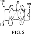
図5および図6は、それぞれ第1構成および第2構成における脊椎インプラント100を示す。図5に示すように、脊椎インプラント100は、第1構成で圧潰され、隣接する棘突起間に挿入することができる。脊椎インプラント100は、第1拡張可能部分110、第2拡張可能部分120、および中心部分150を有する。第1拡張可能部分110は、第1端部112、および第2端部1140を有する。第2拡張可能部分120は、第1端部122、および第2端部124を有する。中心部分150は、第2端部1140と第1端部122との間に結合される。実施態様によっては、脊椎インプラント100は一体成形される。   5 and 6 show the spinal implant 100 in a first configuration and a second configuration, respectively. As shown in FIG. 5, the spinal implant 100 can be collapsed in a first configuration and inserted between adjacent spinous processes. The spinal implant 100 has a first expandable portion 110, a second expandable portion 120, and a central portion 150. The first expandable portion 110 has a first end 112 and a second end 1140. The second expandable portion 120 has a first end 122 and a second end 124. Center portion 150 is coupled between second end 1140 and first end 122. In some embodiments, spinal implant 100 is integrally formed.

第1拡張可能部分110、第2拡張可能部分120、および中心部分150は、脊椎インプラント100の長さに沿って共通の長手方向軸Aを有する。中心部分150は、第1拡張可能部分110および第2拡張可能部分120と同じ内径を有する。実施態様によっては、中心部分150の外径は、第1拡張可能部分110および第2拡張可能部分120の外径より小さい。   The first expandable portion 110, the second expandable portion 120, and the central portion 150 have a common longitudinal axis A along the length of the spinal implant 100. The central portion 150 has the same inner diameter as the first expandable portion 110 and the second expandable portion 120. In some embodiments, the outer diameter of the central portion 150 is smaller than the outer diameter of the first expandable portion 110 and the second expandable portion 120.

使用の際、脊椎インプラント100は、経皮的に隣接する棘突起間に挿入される。第1拡張可能部分110は最初に挿入され、棘突起を通過して、中心部分150が棘突起間に配置される。中心部分150の外径は、周囲の靭帯および組織を考慮に入れて、棘突起間の空間よりわずかに小さくて良い。実施態様によっては、中心部分は棘突起に直接接触させて、棘突起の間に配置される。実施態様によっては、脊椎インプラント100の中心部分は一定のサイズであり、圧縮可能または拡張可能ではない。   In use, the spinal implant 100 is inserted between adjacent spinous processes percutaneously. The first expandable portion 110 is first inserted and passes through the spinous process, with the central portion 150 positioned between the spinous processes. The outer diameter of the central portion 150 may be slightly smaller than the space between the spinous processes, taking into account the surrounding ligaments and tissue. In some embodiments, the central portion is disposed between the spinous processes in direct contact with the spinous processes. In some embodiments, the central portion of spinal implant 100 is a fixed size and is not compressible or expandable.

第1拡張可能部分110は、拡張部材115、117および119を備える。拡張部材115、117、119間には、開口部111が画定される。上記のとおり、開口部111のサイズおよび形状は、軸方向荷重が加わった時に、拡張部材115、117、119が変形する方法に影響する。第2拡張可能部分120は、拡張部材125、127、および129を備える。拡張部材125、127、129間には、開口部121が画定される。上記のとおり、開口部121のサイズおよび形状は、軸方向荷重が加わった時に、拡張部材125、127、129が変形する方法に影響する。   The first expandable portion 110 includes expansion members 115, 117 and 119. An opening 111 is defined between the expansion members 115, 117, and 119. As described above, the size and shape of the opening 111 affects the way in which the expansion members 115, 117, and 119 are deformed when an axial load is applied. Second expandable portion 120 includes expansion members 125, 127, and 129. An opening 121 is defined between the expansion members 125, 127, and 129. As described above, the size and shape of the opening 121 affects how the expansion members 125, 127, and 129 are deformed when an axial load is applied.

軸方向荷重が脊椎インプラント100に加わると、脊椎インプラント100は、図6に示すように第2構成で拡張する。第2構成では、第1拡張可能部分110の第1端部112および第2端部1140は、互いの方向に移動し、拡張部材115、117、119は、実質的に長手方向軸Aから離れて側方に突出する。同様に、第2拡張可能部分120の第1端部122および第2端部124は、互いの方向に移動し、拡張部材125、127、129は長手方向軸Aから離れて側方に突出する。第2構成の拡張部材115、117、119、125、127、129は、棘突起に隣接する位置に延在する突出部を形成し、これらの間に脊椎インプラント100が挿入される。第2構成では、拡張部材115、117、119、125、127、129は、脊椎インプラント100の側方移動を妨げ、中心部分150は、隣接する棘突起が互いに移動して、中心部分150の直径によって画定される距離より接近するのを妨げる。   When an axial load is applied to the spinal implant 100, the spinal implant 100 expands in the second configuration as shown in FIG. In the second configuration, the first end 112 and the second end 1140 of the first expandable portion 110 move in the direction of each other, and the expansion members 115, 117, 119 are substantially separated from the longitudinal axis A. Protruding sideways. Similarly, the first end 122 and the second end 124 of the second expandable portion 120 move in the direction of each other, and the expansion members 125, 127, 129 protrude laterally away from the longitudinal axis A. . The second configuration of expansion members 115, 117, 119, 125, 127, and 129 form protrusions that extend adjacent to the spinous processes, between which the spinal implant 100 is inserted. In the second configuration, the expansion members 115, 117, 119, 125, 127, 129 prevent lateral movement of the spinal implant 100, and the central portion 150 has a diameter of the central portion 150 as adjacent spinous processes move relative to each other. To prevent access closer than the distance defined by.

本発明の一実施態様による脊椎インプラント200は、図7〜図9に様々な構成で示す。脊椎インプラント200は、図7に完全圧潰構成で示され、隣接する棘突起間に挿入される。脊椎インプラント200は、第1拡張可能部分210、第2拡張可能部分220、および中心部分250を有する。第1拡張可能部分210は、第1端部212および第2端部214を有する。第2拡張可能部分220は、第1端部222および第2端部224を有する。中心部分250は、第2端部214および第1端部222間に結合される。   A spinal implant 200 according to one embodiment of the present invention is shown in various configurations in FIGS. The spinal implant 200 is shown in a fully collapsed configuration in FIG. 7 and is inserted between adjacent spinous processes. The spinal implant 200 has a first expandable portion 210, a second expandable portion 220, and a central portion 250. The first expandable portion 210 has a first end 212 and a second end 214. The second expandable portion 220 has a first end 222 and a second end 224. Central portion 250 is coupled between second end 214 and first end 222.

第1拡張可能部分210、第2拡張可能部分220、および中心部分250は、脊椎インプラント200の長さに沿って共通の長手方向軸Aを有する。中心部分250は、第1拡張可能部分210および第2拡張可能部分220と同じ内径を有することが可能である。中心部分250の外径は、第1拡張可能部分210および第2拡張可能部分220の外径より大きい。中心部分250は、第1拡張可能部分210および第2拡張可能部分220と一体成形するか、または別個に成形して、これらの部分に、またはこれらの部分上に結合することが可能である。   The first expandable portion 210, the second expandable portion 220, and the central portion 250 have a common longitudinal axis A along the length of the spinal implant 200. The central portion 250 can have the same inner diameter as the first expandable portion 210 and the second expandable portion 220. The outer diameter of the central portion 250 is greater than the outer diameter of the first expandable portion 210 and the second expandable portion 220. The central portion 250 can be integrally molded with the first expandable portion 210 and the second expandable portion 220, or can be molded separately and coupled to or on these portions.

使用の際、脊椎インプラント200は、経皮的に隣接する棘突起S間に挿入される。第1拡張可能部分210は棘突起Sを通過し、中心部分250が棘突起S間に配置される。中心部分250の外径は、周囲の靭帯および組織を考慮に入れて、棘突起S間の空間よりわずかに小さくて良い。実施態様によっては、中心部分250は棘突起Sに直接接触して、棘突起Sの間に配置される。実施態様によっては、脊椎インプラント200の中心部分250は一定のサイズであり、圧縮または拡張可能ではない。他の実施態様では、中心部分250は、棘突起の形状に適合するように圧縮させることができる。   In use, the spinal implant 200 is inserted between adjacent spinous processes S percutaneously. The first expandable portion 210 passes through the spinous process S and the central portion 250 is disposed between the spinous processes S. The outer diameter of the central portion 250 may be slightly smaller than the space between the spinous processes S, taking into account the surrounding ligaments and tissue. In some embodiments, the central portion 250 is disposed between the spinous processes S in direct contact with the spinous processes S. In some embodiments, the central portion 250 of the spinal implant 200 is a fixed size and is not compressible or expandable. In other embodiments, the central portion 250 can be compressed to conform to the shape of the spinous process.

第1拡張可能部分210は、拡張部材215、217および219を備える。拡張部材215、217、219の間には、開口部211が画定される。上記のとおり、開口部211のサイズおよび形状は、拡張部材215、217、219が、軸方向荷重が加わった時に変形する方法に影響する。第1拡張可能部分210の各々の拡張部材215、217、219は、開口部211内に延在するタブ213、および対向する嵌合スロット218を含む。実施態様によっては、第1拡張可能部分210の第1端部212は、脊椎インプラント200の挿入を容易にするように円形である。   The first expandable portion 210 includes expansion members 215, 217 and 219. An opening 211 is defined between the expansion members 215, 217, and 219. As described above, the size and shape of the opening 211 affect how the expansion members 215, 217, 219 are deformed when an axial load is applied. Each expansion member 215, 217, 219 of the first expandable portion 210 includes a tab 213 that extends into the opening 211 and an opposing mating slot 218. In some embodiments, the first end 212 of the first expandable portion 210 is circular to facilitate insertion of the spinal implant 200.

第2拡張可能部分220は、拡張部材225、227、および229を備える。拡張部材225,227、および229間には、開口部221が画定される。上記のとおり、開口部221は、拡張部材225、227、229が、軸方向荷重が加わった時に変形する方法に影響する。第2拡張可能部分220の拡張部材225、227、229の各々は、開口部221内に延在するタブ223、および対向する嵌合スロット228を含む。   The second expandable portion 220 includes expansion members 225, 227, and 229. An opening 221 is defined between the expansion members 225, 227, and 229. As described above, the opening 221 affects the way in which the expansion members 225, 227, 229 are deformed when an axial load is applied. Each of the expansion members 225, 227, 229 of the second expandable portion 220 includes a tab 223 that extends into the opening 221 and an opposing mating slot 228.

脊椎インプラント200に対して軸方向荷重が加わった時に、脊椎インプラントは、図8に示すように部分的拡張構成に移動する。部分的拡張構成では、第2拡張可能部分220の第1端部222および第2端部224は互いの方向に移動し、拡張部材225、227、229は、長手方向軸Aから離れて側方に突出する。第2拡張可能部分220が拡張するのを防止するため、タブ223はスロット228と係合し、ポジティブストップとして作用する。タブ223がスロット228に係合した後、軸方向荷重が脊椎インプラント200に対して加わり続けると、荷重は第1拡張可能部分210に伝達される。したがって、第1端部212および第2端部214は、次に互いの方向に移動し、タブ213は、図9に示す完全拡張構成でスロット218に係合する。第2構成では、拡張部材215、217、219は、長手方向軸Aから離れて側方に突出する。別法による実施態様によっては、第1拡張可能部分および第2拡張可能部分は、軸方向荷重が加わると同時に拡張する。   When an axial load is applied to the spinal implant 200, the spinal implant moves to a partially expanded configuration as shown in FIG. In the partially expanded configuration, the first end 222 and the second end 224 of the second expandable portion 220 move in the direction of each other, and the expansion members 225, 227, 229 move laterally away from the longitudinal axis A. Protrusively. To prevent the second expandable portion 220 from expanding, the tab 223 engages the slot 228 and acts as a positive stop. If the axial load continues to be applied to the spinal implant 200 after the tab 223 engages the slot 228, the load is transmitted to the first expandable portion 210. Accordingly, the first end 212 and the second end 214 then move in the direction of each other and the tab 213 engages the slot 218 in the fully expanded configuration shown in FIG. In the second configuration, the expansion members 215, 217, 219 protrude laterally away from the longitudinal axis A. In some alternative embodiments, the first expandable portion and the second expandable portion expand as soon as an axial load is applied.

脊椎インプラント200の拡張の程度は、開口部211および221のサイズを変えることによって制御することができる。たとえば、図7〜図9に示す実施態様では、開口部221は、開口部211よりわずかに大きい。したがって、ノッチ226は、ノッチ216よりわずかに大きい。したがって、図3および図4に関して上記で説明したとおり、第2拡張可能部分220は、軸方向荷重が加わると、第1拡張可能部分210より先に拡張する。   The degree of expansion of the spinal implant 200 can be controlled by changing the size of the openings 211 and 221. For example, in the embodiment shown in FIGS. 7 to 9, the opening 221 is slightly larger than the opening 211. Accordingly, notch 226 is slightly larger than notch 216. Thus, as described above with respect to FIGS. 3 and 4, the second expandable portion 220 expands prior to the first expandable portion 210 when an axial load is applied.

第2構成では、拡張部材215、217、219、225、227、229は、棘突起Sに隣接する突出部を形成する。第2構成になると、拡張部材215、217、219、225、227、229は、脊椎インプラント200の側方移動を妨げ、中心部分250は、隣接する棘突起が互いに、中心部分250の直径によって画定される距離より、移動して接近するのを妨げる。   In the second configuration, the expansion members 215, 217, 219, 225, 227, 229 form a protrusion adjacent to the spinous process S. When in the second configuration, the expansion members 215, 217, 219, 225, 227, 229 prevent lateral movement of the spinal implant 200 and the central portion 250 is defined by adjacent spinous processes relative to each other by the diameter of the central portion 250. It will prevent you from moving closer than you can.

棘突起Sの近位の拡張部材215、217、219、225、227、229の各々の部分Pは、部分Pが棘突起Sに実質的に平行であるように拡張する。棘突起Sから遠位の拡張部材215、217、219、225、227、229の各々の部分Dは、緊張が周囲の組織に殆ど加わらないように傾斜させる。   Each portion P of the expansion member 215, 217, 219, 225, 227, 229 proximal to the spinous process S expands such that the portion P is substantially parallel to the spinous process S. Each portion D of the expansion member 215, 217, 219, 225, 227, 229 distal from the spinous process S is inclined so that little tension is applied to the surrounding tissue.

第2構成では、拡張部材225、227、229は、図10に示すように軸方向像から約120°だけ分離している。3つの拡張部材が示されているが、複数のインプラント200を複数の隣接する棘突起間に挿入する場合、2つ以上の拡張部材を使用して、重複するかまたは交互になるように配列することができる。さらに、提供される拡張部材の数に関係なく、隣接する拡張部材は、等しい角度または距離で分離する必要はない。   In the second configuration, the expansion members 225, 227, 229 are separated from the axial image by about 120 ° as shown in FIG. Although three expansion members are shown, when multiple implants 200 are inserted between multiple adjacent spinous processes, two or more expansion members are used and arranged to overlap or alternate. be able to. Further, regardless of the number of expansion members provided, adjacent expansion members need not be separated by an equal angle or distance.

脊椎インプラント200は、脊椎インプラント200の実質的に長手方向軸Aに沿って加わる圧縮力によって変形する。圧縮力は、たとえばロッド(図示しない)を第1拡張可能部分210の第1端部212に取り付けて、ロッドを長手方向軸に沿って引っ張り、対抗する力を第2拡張可能部分220の第2端部224に対して加えることによって加えられる。対抗する力は圧縮力を生じ、その結果、上記のとおり脊椎インプラント200が拡張する。   The spinal implant 200 is deformed by a compressive force applied substantially along the longitudinal axis A of the spinal implant 200. The compressive force can be achieved, for example, by attaching a rod (not shown) to the first end 212 of the first expandable portion 210, pulling the rod along the longitudinal axis, and applying an opposing force to the second expandable portion 220 second. Added by adding to end 224. The opposing force creates a compressive force that results in the spinal implant 200 expanding as described above.

脊椎インプラント200に圧縮力を与えるために使用されるロッドは、脊椎インプラント200に取り外し可能に結合される。たとえば、脊椎インプラント200は、第1拡張可能部分210の第1端部212にねじ山208を備えることができる。ロッドによって加わる力に対抗する力は、第2拡張可能部分220の第2端部224に取り外し可能に結合されるプッシュバー(図示しない)を使用して加えることができる。プッシュロッドは、第2端部224の整列ノッチ206によって、脊椎インプラント200と整列させることができる。脊椎インプラント200は、多様なその他の方法で変形させることができ、その実施例を以下で詳細に説明する。   A rod that is used to apply a compressive force to the spinal implant 200 is removably coupled to the spinal implant 200. For example, the spinal implant 200 can include a thread 208 at the first end 212 of the first expandable portion 210. Force against the force exerted by the rod can be applied using a push bar (not shown) removably coupled to the second end 224 of the second expandable portion 220. The push rod can be aligned with the spinal implant 200 by the alignment notch 206 at the second end 224. The spinal implant 200 can be deformed in a variety of other ways, examples of which are described in detail below.

図11〜図14は、本発明の一実施態様による脊椎インプラント300を示す。脊椎インプラント300は、隣接する棘突起S間に配置されるように構成され、第1端部312および第2端部314を有する長形管310を備える。長形管310は、その長さに沿って予め決められた位置に画定された長手方向スロット311を有する。スロット311は、長形管310の各部分が外側に延在して突出部317を形成する。膨張可能部材350は、長形管の周囲であって、スロット311の隣接する集合間に配置される。   11-14 illustrate a spinal implant 300 according to one embodiment of the present invention. The spinal implant 300 is configured to be disposed between adjacent spinous processes S and includes an elongated tube 310 having a first end 312 and a second end 314. The elongated tube 310 has a longitudinal slot 311 defined at a predetermined location along its length. In the slot 311, each part of the elongated tube 310 extends outward to form a protrusion 317. Inflatable member 350 is disposed around the elongated tube and between adjacent sets of slots 311.

膨張可能部材350は、図11〜図14に示すとおり、隣接する棘突起S間に配置するように構成される。膨張可能部材350は、隣接する棘突起間に挿入された後、たとえば生体適合性材料などの液体および/または気体を使って膨張される。膨張可能部材350は、脊椎インプラント300を棘突起S間の所定の位置に維持するために膨張される。実施態様によっては、膨張可能部材350は、膨張された時に、棘突起Sを少なくとも部分的に伸延させるように構成される。膨張可能部材350は、棘突起S間の様々な間隔を考慮に入れて、様々な寸法に膨張される。   The inflatable member 350 is configured to be disposed between adjacent spinous processes S as shown in FIGS. The inflatable member 350 is inserted between adjacent spinous processes and then inflated using a liquid and / or gas, such as a biocompatible material. Inflatable member 350 is inflated to maintain spinal implant 300 in place between spinous processes S. In some embodiments, the expandable member 350 is configured to at least partially distract the spinous process S when expanded. The inflatable member 350 is inflated to various dimensions, taking into account the various spacings between the spinous processes S.

膨張可能部材350は、脊椎インプラント300が棘突起S間の所定の位置に配置された後、脊椎インプラント300を通して挿入される膨張管370を介して膨張させることができる。膨張可能部材350が膨張する前あるいは後に、突出部317は拡張される。突出部317を拡張させるために、脊椎インプラント300の第1端部312に結合される引っ張りバー320を使って、軸方向の力を脊椎インプラント300に加える。   The inflatable member 350 can be inflated via an inflation tube 370 inserted through the spinal implant 300 after the spinal implant 300 is placed in place between the spinous processes S. The protrusion 317 is expanded before or after the expandable member 350 is expanded. To expand the protrusion 317, an axial force is applied to the spinal implant 300 using a pull bar 320 coupled to the first end 312 of the spinal implant 300.

引っ張りバー320が引っ張られると、軸方向荷重によって、突出部317は外側に座屈し、それによって脊椎インプラントが、棘突起Sに対して側方に移動するのを防止する。図12は、変形時の脊椎インプラント300の図であり、突出部317のみが部分的に形成されている。同時に変形するように図示されているが、別法により、上記のとおり変形が異なる時間に発生するように、スロット311の寸法を決めることができる。脊椎インプラントが拡張構成になると(図13参照)、引っ張りバー320は、長形管310から取り外される。   As the pull bar 320 is pulled, the axial load causes the protrusion 317 to buckle outward, thereby preventing the spinal implant from moving laterally relative to the spinous process S. FIG. 12 is a view of the spinal implant 300 during deformation, with only the protrusion 317 being partially formed. Although illustrated as deforming simultaneously, the slot 311 can be dimensioned by another method so that deformation occurs at different times as described above. When the spinal implant is in the expanded configuration (see FIG. 13), the pull bar 320 is removed from the elongated tube 310.

脊椎インプラント300の向きは、2つの突出部が、図14に示すように互いに隣接する脊椎部分の軸に実質的に平行になる向きである必要はない。たとえば、脊椎インプラント300は、各々の突出部317が、脊髄の軸に対して45°の角度になる向きにすることができる。   The orientation of the spinal implant 300 need not be such that the two protrusions are substantially parallel to the axes of the adjacent spinal portions as shown in FIG. For example, spinal implant 300 can be oriented with each protrusion 317 at a 45 ° angle to the spinal axis.

脊椎インプラント100、200、300は、様々な拡張デバイスを使用して、その第1構成から第2構成に変形させることが可能である。たとえば、脊椎インプラント100、200、300の部分、およびその他のタイプのインプラントIは、以下の拡張デバイスを使用して変形させることが可能である。様々なタイプのインプラントIが示されているが、記載されている様々な拡張デバイスは、本明細書に記載するどのインプラントにも使用することができる。   The spinal implant 100, 200, 300 can be deformed from its first configuration to its second configuration using a variety of expansion devices. For example, portions of spinal implants 100, 200, 300, and other types of implants I can be deformed using the following expansion devices. Although various types of implants I are shown, the various expansion devices described can be used with any of the implants described herein.

図15〜図17は、拡張デバイス1500の一実施態様を示す。拡張デバイス1500は、案内ハンドル1510、ノブ組立体1515、上部筐体1517、シャフト1520、およびインプラント支持部分1530を備える。拡張デバイス1500は、インプラント(図示しない)を隣接する棘突起間に挿入して、上記のとおり、インプラントを拡張させて棘突起間の所定の位置に保持するために使用される。案内ハンドル1510およびノブ組立体1515は共に、拡張デバイス1500を操作してインプラントを挿入するように把持することができる。分かりやすくするために、図15〜図17には特定のインプラントを示さないが、たとえばインプラント200などのインプラントは、拡張デバイス1500と共に使用することができる(図7参照)。   FIGS. 15-17 illustrate one embodiment of an expansion device 1500. The expansion device 1500 includes a guide handle 1510, a knob assembly 1515, an upper housing 1517, a shaft 1520, and an implant support portion 1530. The expansion device 1500 is used to insert an implant (not shown) between adjacent spinous processes to expand the implant and hold it in place between the spinous processes as described above. Both the guide handle 1510 and the knob assembly 1515 can be gripped to manipulate the expansion device 1500 to insert the implant. For clarity, specific implants are not shown in FIGS. 15-17, but an implant such as, for example, implant 200 can be used with expansion device 1500 (see FIG. 7).

インプラント支持部分1530は、ロッド1532の表面上にインプラントを摺動可能に収容する。インプラントは、ロッド1532上で摺動し、図15Bに最も良く示されているように、陥凹部1534内に収容される。インプラントは、ねじ付きロッド1570を使用して、インプラント支持部分1530にねじ結合される。ねじ付きロッド1570は、スラスト軸受け1552を使用して、アクチュエータノブ1550内に結合される。整列突出部1536は、陥凹部1534内に配置され、インプラント上の対応するノッチと嵌合して、インプラントの適切な位置決めが確保されるように構成される。   Implant support portion 1530 slidably houses the implant on the surface of rod 1532. The implant slides on the rod 1532 and is received in the recess 1534 as best shown in FIG. 15B. The implant is screwed to the implant support portion 1530 using a threaded rod 1570. Threaded rod 1570 is coupled into actuator knob 1550 using thrust bearing 1552. The alignment protrusion 1536 is disposed within the recess 1534 and is configured to mate with a corresponding notch on the implant to ensure proper positioning of the implant.

上部筐体1517は、図15Aに最も良く示されているように、シャフト1520を摺動可能に収容する。上部筐体は、シャフト1520上の外側ねじ山1521に嵌合する内側ねじ山1519を備える。アクチュエータノブ1550は、上部筐体1517に結合し、アクチュエータノブ1550が矢印Eの方向に回転した時に、ねじ付きロッド1570が引っ張りバーとして作用し、インプラントが遠位の方向に移動するのを妨げるため、シャフト1520が軸方向にデバイス1500の遠位端方向に移動する。つまり、インプラントが隣接する棘突起間に挿入されると、アクチュエータノブ1515が回転し、シャフト1520の遠位端が、インプラントの近位端に対して軸方向の力を与える。同時に、ねじ付きロッド1570によって、対抗する力が近位の方向に生じる。   Upper housing 1517 slidably houses shaft 1520 as best shown in FIG. 15A. The upper housing includes an inner thread 1519 that fits into an outer thread 1521 on the shaft 1520. Actuator knob 1550 is coupled to upper housing 1517 so that when actuator knob 1550 rotates in the direction of arrow E, threaded rod 1570 acts as a pull bar to prevent the implant from moving in the distal direction. The shaft 1520 moves axially toward the distal end of the device 1500. That is, when the implant is inserted between adjacent spinous processes, the actuator knob 1515 rotates and the distal end of the shaft 1520 provides an axial force against the proximal end of the implant. At the same time, the threaded rod 1570 creates an opposing force in the proximal direction.

シャフト1520およびねじ付きロッド1570によって加わる力により、インプラントの部分は、横構成に拡張して、上記のように棘突起間の所定の位置に維持される。   The force exerted by the shaft 1520 and threaded rod 1570 causes the portion of the implant to expand into the transverse configuration and remain in place between the spinous processes as described above.

インプラントが所定の位置に配置され、完全に拡張すると、解放ノブ1560が、矢印Rで指示される方向に回転し、ねじ付きロッド1570をインプラントから外すことができる。次に、拡張デバイスを取り外すことができる。   When the implant is in place and fully expanded, the release knob 1560 can rotate in the direction indicated by arrow R to disengage the threaded rod 1570 from the implant. The expansion device can then be removed.

図18は、圧潰構成の拡張デバイス400を示す。拡張デバイス400は、インプラントI(図18に示さない)上の突出部を所望の位置に選択的に形成するために使用することができる。拡張デバイス400は、拡張デバイス400をインプラントI内に案内できる案内シャフト410と、案内シャフト410に取り付けられ、偏心位置に配置可能なカムアクチュエータ450とを備える。拡張デバイス400は長手方向軸Aを有し、カムアクチュエータ450は、距離dだけ長手方向軸Aから側方に偏位するカム軸Cを有する。図19は、カムアクチュエータ450が、カム軸Cの周囲で回転した状態の拡張構成における拡張デバイス400を示す。   FIG. 18 shows an expansion device 400 in a collapsed configuration. The expansion device 400 can be used to selectively form protrusions on the implant I (not shown in FIG. 18) at desired locations. The expansion device 400 includes a guide shaft 410 that can guide the expansion device 400 into the implant I, and a cam actuator 450 that is attached to the guide shaft 410 and can be placed in an eccentric position. The expansion device 400 has a longitudinal axis A, and the cam actuator 450 has a cam axis C that is laterally offset from the longitudinal axis A by a distance d. FIG. 19 shows the expansion device 400 in an expanded configuration with the cam actuator 450 rotated about the cam axis C. FIG.

拡張デバイス400は、図20に示すインプラントホルダーHを通してインプラントI内に挿入することができる。インプラントホルダーHはインプラントに結合され、インプラントを所定の位置に保持するように構成され、拡張デバイス400はインプラントIを変形させるように操作される。インプラントIが十分に変形すると、インプラントホルダーHは、インプラントIから分離され、患者から取り外すことができ、インプラントIは後方に残される。   The expansion device 400 can be inserted into the implant I through the implant holder H shown in FIG. The implant holder H is coupled to the implant and is configured to hold the implant in place, and the expansion device 400 is manipulated to deform the implant I. When the implant I is sufficiently deformed, the implant holder H is separated from the implant I and can be removed from the patient, leaving the implant I behind.

図20および図21を参照すると、拡張デバイス400は、カムアクチュエータ450を展開させるために使用されるハンドル420を備える。ハンドル420が回転すると、カムアクチュエータ450が展開し、インプラントIを変形させる。カムアクチュエータ450が完全に展開し(たとえば、元の位置から180°)、所定の位置に係止されると、全体の拡張デバイス400が回転し、インプラントIの周囲でインプラントIを変形させる。カムアクチュエータ450は、突出部P(図22参照)を形成するインプラントIの元の直径の外側にある複数の点の軌跡を囲む。拡張デバイス400は、所定の位置に係止された後、案内シャフト410を把持するか、またはハンドル420を使用して回転させることができる。   Referring to FIGS. 20 and 21, the expansion device 400 includes a handle 420 that is used to deploy the cam actuator 450. As the handle 420 rotates, the cam actuator 450 deploys and deforms the implant I. When the cam actuator 450 is fully deployed (eg, 180 ° from its original position) and locked in place, the entire expansion device 400 rotates and deforms the implant I around the implant I. The cam actuator 450 surrounds the trajectory of a plurality of points outside the original diameter of the implant I that forms the protrusion P (see FIG. 22). After the expansion device 400 is locked in place, it can grip the guide shaft 410 or be rotated using the handle 420.

拡張デバイス400は、複数の突出部Pを形成するために使用することができる。第1突出部Pが形成された後、カムアクチュエータ450は逆に回転して第1構成になり、拡張デバイス400は、インプラントIを通って第2位置に前進することができる。拡張デバイス400が、適切に配置されると、カムアクチュエータ450は、再び展開し、拡張デバイス400が回転して、第2突出部Pを形成する(図23参照)。実施態様によっては、インプラントIは、隣接する棘突起間に配置され、突出部Pは、棘突起の両側に形成されて、インプラントIが側方(つまり、軸方向)に変位するのを防止する。   The expansion device 400 can be used to form a plurality of protrusions P. After the first protrusion P is formed, the cam actuator 450 rotates in the reverse direction to the first configuration, and the expansion device 400 can be advanced through the implant I to the second position. When the expansion device 400 is properly positioned, the cam actuator 450 is deployed again and the expansion device 400 rotates to form the second protrusion P (see FIG. 23). In some embodiments, the implant I is disposed between adjacent spinous processes and the protrusions P are formed on both sides of the spinous process to prevent the implant I from being displaced laterally (ie, axially). .

別法による拡張デバイス500を図24および図25に示す。図24は、第1構成における拡張デバイス500を示し、図25は、第2構成における拡張デバイス500を示す。拡張デバイス500は、インプラントI内に挿入される案内シャフト510を備える。軸方向カムシャフトアクチュエータ520は、案内シャフト520内に摺動可能に配置される。軸方向カムシャフトアクチュエータ520は、移動可能な物体550を収容するための傾斜陥凹部530を有する。カムシャフトアクチュエータ520が移動すると、移動可能な物体550は傾斜陥凹部530に沿って変位し、案内シャフト510内の開口部540を通って突出する。   An alternative expansion device 500 is shown in FIGS. FIG. 24 shows the expansion device 500 in the first configuration, and FIG. 25 shows the expansion device 500 in the second configuration. The expansion device 500 includes a guide shaft 510 that is inserted into the implant I. The axial camshaft actuator 520 is slidably disposed within the guide shaft 520. The axial camshaft actuator 520 has an inclined recess 530 for receiving a movable object 550. As the camshaft actuator 520 moves, the movable object 550 is displaced along the inclined recess 530 and protrudes through the opening 540 in the guide shaft 510.

移動可能な物体550は、インプラントIの一部分を変位させて、突出部Pを形成するように構成される。複数の移動可能な物体550は、案内シャフト510の周囲に使用して、インプラントIの周囲に半径方向に延在する突出部Pを形成することができる。さらに、突出部は、上記のとおり、拡張デバイス500をインプラントの長さに沿って第2位置に前進させることによって、インプラントIの長さに沿った複数の位置に形成することができる。別法によると、拡張デバイスは、移動可能な物体の他の集合を変位させる複数の陥凹部を有することができる。   The movable object 550 is configured to displace a portion of the implant I to form the protrusion P. A plurality of movable objects 550 can be used around the guide shaft 510 to form a protrusion P extending radially around the implant I. Further, the protrusions can be formed at a plurality of positions along the length of the implant I by advancing the expansion device 500 to the second position along the length of the implant as described above. Alternatively, the expansion device can have a plurality of recesses that displace other collections of movable objects.

別法による実施態様では、拡張デバイスは、インプラントとしても役立つ。たとえば、拡張デバイス500は、隣接する棘突起S間に挿入することができ、移動可能な物体は開口部540から移動し、拡張デバイス500は後方に体内に残される。このような実施態様では、移動可能な物体は、拡張デバイス500が棘突起Sに対して側方に移動するのを防止する。   In an alternative embodiment, the expansion device also serves as an implant. For example, the expansion device 500 can be inserted between adjacent spinous processes S, a movable object moves from the opening 540, and the expansion device 500 is left behind in the body. In such an embodiment, the movable object prevents the expansion device 500 from moving laterally relative to the spinous process S.

もう1つの別法による実施態様では、拡張デバイス500に開口部540を有するのではなく、移動可能な物体550は、拡張デバイスの壁部の比較的脆弱な(薄い)部分に配置し、拡張デバイス500の当該部分を突出構成に移動させることができる。   In another alternative embodiment, rather than having an opening 540 in the expansion device 500, the movable object 550 is placed in a relatively fragile (thin) portion of the wall of the expansion device, and the expansion device 500 such portions can be moved to the protruding configuration.

もう1つの別法による拡張デバイス600は、図26〜図28に示す。図26は、第1構成の拡張デバイス600を示し、図28は、第2構成の拡張デバイスを示す。拡張デバイス600は、インプラントI内に挿入される案内シャフト610を備える。案内シャフト610は、開口部640が内部に画定されている。軸方向カムシャフトアクチュエータ620は、案内シャフト610内に回転可能に結合される。変位可能な物体650は、案内シャフト610内に配置され、案内シャフト610内の開口部640から突出するように構成される。カムシャフトアクチュエータ620が約90°回転すると、移動可能な物体650は開口部640を通って移動し、インプラントIを変形させて突出部Pを形成する。別法によると、拡張デバイスは、移動可能な物体の他の集合を変位させる複数のカムを有することが可能である。   Another alternative expansion device 600 is shown in FIGS. FIG. 26 shows an expansion device 600 having a first configuration, and FIG. 28 shows an expansion device having a second configuration. The expansion device 600 includes a guide shaft 610 that is inserted into the implant I. The guide shaft 610 has an opening 640 defined therein. An axial camshaft actuator 620 is rotatably coupled within the guide shaft 610. The displaceable object 650 is disposed in the guide shaft 610 and is configured to protrude from an opening 640 in the guide shaft 610. As the camshaft actuator 620 rotates approximately 90 °, the movable object 650 moves through the opening 640 and deforms the implant I to form the protrusion P. Alternatively, the expansion device can have multiple cams that displace other collections of movable objects.

複数の移動可能な物体650は、案内シャフト610の周囲に使用して、インプラントIの周囲に半径方向延在する突出部Pを形成することができる。さらに、この突出部は、上記のとおり、拡張デバイス600をインプラントIの長さに沿って第2位置に前進させることによって、インプラントIの長さに沿った複数の位置に形成することができる。   A plurality of movable objects 650 can be used around the guide shaft 610 to form a protrusion P extending radially around the implant I. Further, the protrusions can be formed at a plurality of positions along the length of the implant I by advancing the expansion device 600 to the second position along the length of the implant I as described above.

インプラント拡張デバイス700を図29および図30に示す。インプラント拡張デバイス700は、インプラントI内に挿入するように構成される。インプラント700は、筐体770に結合される案内シャフト710を備える。カムアクチュエータ720は、筐体770内に回転可能に取り付けられ、互いに対向する方向に延在するアーム790を備える。カムアクチュエータ720は、ロッド722を使って回転される。   An implant expansion device 700 is shown in FIGS. Implant expansion device 700 is configured for insertion into implant I. The implant 700 includes a guide shaft 710 that is coupled to the housing 770. The cam actuator 720 includes an arm 790 that is rotatably mounted in the housing 770 and extends in a direction facing each other. Cam actuator 720 is rotated using rod 722.

カムアクチュエータ720が回転すると、アーム790は、移動可能な物体750に係合する。移動可能な物体750は、カムアクチュエータが時計方向に回転すると、筐体770から突出するように構成される。移動可能な物体750は、完全に延在すると、インプラントIに係合し、拡張デバイス700は完全に1回転して、インプラントI内に突出部を形成する。   As cam actuator 720 rotates, arm 790 engages movable object 750. The movable object 750 is configured to protrude from the housing 770 when the cam actuator rotates clockwise. When the movable object 750 is fully extended, it engages the implant I and the expansion device 700 makes one complete rotation to form a protrusion in the implant I.

突出部が形成された後、ロッド722は反時計方向に回転し、移動可能な物体750をインプラントIから離脱させることができる。拡張デバイス700は、離脱した後、上記のようにインプラントI内の別の位置に前進することができる。   After the protrusion is formed, the rod 722 can rotate counterclockwise to disengage the movable object 750 from the implant I. After disengagement, the expansion device 700 can be advanced to another position within the implant I as described above.

その他の実施態様によっては、インプラントIは、バルーンで作動させることができる。図31は、隣接する棘突起S間に配置されたインプラントIを示す。バルーンアクチュエータ800は、インプラントI内に挿入され、図32のように拡張して、インプラントIをその拡張構成に移動させる。バルーンアクチュエータ800は、拡張した後、収縮させて取り外すことができ、拡張構成のインプラントIが残る。   In other embodiments, the implant I can be actuated with a balloon. FIG. 31 shows an implant I placed between adjacent spinous processes S. FIG. Balloon actuator 800 is inserted into implant I and expands as shown in FIG. 32 to move implant I to its expanded configuration. The balloon actuator 800 can be deflated and removed after expansion, leaving the implant I in an expanded configuration.

実施態様によっては、バルーンアクチュエータ800は、棘突起Sの各々の側で拡張する複数の丸い突出部を有することができる。その他の実施態様では、複数のバルーンアクチュエータ800は、インプラントIを拡張させるために使用することができる。   In some embodiments, the balloon actuator 800 can have a plurality of round protrusions that expand on each side of the spinous process S. In other embodiments, multiple balloon actuators 800 can be used to expand the implant I.

図33は、図34〜図37に示す拡張デバイス950を使用して拡張することができる拡張可能インプラント900の断面図である。インプラント900は、第1端部901および第2端部902を有する長形の本体部分910を有する。第1端部901は、外側にねじを切られた部分911を有し、第2端部は内側にねじを切られた部分912を有する。インプラント900は、外側にねじを切られた部分911に第1の外径D1、および第1の外径D1より広い第2の外径D2を有する。   FIG. 33 is a cross-sectional view of an expandable implant 900 that can be expanded using the expansion device 950 shown in FIGS. The implant 900 has an elongated body portion 910 having a first end 901 and a second end 902. The first end 901 has an outer threaded portion 911 and the second end has an inner threaded portion 912. The implant 900 has an outer threaded portion 911 having a first outer diameter D1 and a second outer diameter D2 that is wider than the first outer diameter D1.

拡張デバイス950は、引っ張りバー960および圧縮バー970を備える。実施態様によっては、圧縮バー970は、インプラント900(図34参照)の外側にねじを切られた部分911と嵌合する内側ねじ山971を有するチャネル975を画定する。引っ張りバー960は、インプラント900の内側にねじを切られた部分912と嵌合する外側ねじ山961を有する。   The expansion device 950 includes a pull bar 960 and a compression bar 970. In some embodiments, the compression bar 970 defines a channel 975 having an inner thread 971 that mates with an outer threaded portion 911 of the implant 900 (see FIG. 34). The pull bar 960 has an outer thread 961 that mates with a threaded portion 912 inside the implant 900.

使用の際、圧縮バー970は、インプラント900の第1端部901に結合され、第1の外径D1と第2の外径D2との間の遷移部分でインプラント900に当接し、この遷移部分は、圧縮バー970のストップとして機能する。実施態様によっては、インプラント900の外径は実質的に一定であり、圧縮バー970の内径は、圧縮バー970のストップとして役立つように狭くなっている。圧縮バー970が所定の位置に配置されると、引っ張りバー960は、チャネル975を通って挿入され、インプラント900の内側にねじを切られた部分912を介して、インプラント900の第2端部902に結合される(図35参照)。圧縮バー970および引っ張りバー960が、インプラント900に結合されると、引っ張りバー960を引っ張ることができ、対抗する力が圧縮バー970に加えられて、インプラント900が拡張する(図36参照)。インプラント900が完全に拡張すると、圧縮バー970および引っ張りバー960が取り外され、インプラントが後方に体内に残る。   In use, the compression bar 970 is coupled to the first end 901 of the implant 900 and abuts the implant 900 at a transition portion between the first outer diameter D1 and the second outer diameter D2, which transition portion Serves as a stop for the compression bar 970. In some embodiments, the outer diameter of the implant 900 is substantially constant and the inner diameter of the compression bar 970 is narrowed to serve as a stop for the compression bar 970. When the compression bar 970 is in place, the pull bar 960 is inserted through the channel 975 and through the second end 902 of the implant 900 via the threaded portion 912 inside the implant 900. (See FIG. 35). When the compression bar 970 and the pull bar 960 are coupled to the implant 900, the pull bar 960 can be pulled and opposing forces are applied to the compression bar 970 to expand the implant 900 (see FIG. 36). When the implant 900 is fully expanded, the compression bar 970 and pull bar 960 are removed and the implant remains posteriorly in the body.

本明細書で説明する拡張デバイスの場合、突出部の位置は、予め決められた拡張位置を有するのではなく、生体内で選択することができる。こうした構成は、複数のサイズのスペーサを用意する必要性を少なくする。さらに、突出部が展開するタイミングを変えることができる。   In the case of the expansion device described herein, the position of the protrusion can be selected in vivo rather than having a predetermined expansion position. Such a configuration reduces the need to prepare spacers of multiple sizes. Furthermore, the timing which a protrusion part expand | deploys can be changed.

本明細書で説明する様々なインプラント100、200、300は、たとえばステンレス鋼、プラスチック、ポリエーテルエーテルケトン(PEEK)、カーボンファイバ、超高分子(UHMW)ポリエチレンなどから製造することができる。材料は、骨の引っ張り強さと同等、またはそれ以上の引っ張り強さを有することが可能である。   The various implants 100, 200, 300 described herein can be made from, for example, stainless steel, plastic, polyetheretherketone (PEEK), carbon fiber, ultra high molecular weight (UHMW) polyethylene, and the like. The material can have a tensile strength equal to or greater than that of bone.

本発明の他の実施態様では、アパーチャは、第1端部および第2端部を有する第1クランプを備える。第1クランプの第2端部は、第1棘突起に係合するように構成される。第2クランプは、第1端部および第2端部を有する。第2クランプの第2端部は、第1棘突起から離間される第2棘突起に係合するように構成される。コネクタは、第1クランプの第1端部、および第2クランプの第1端部に結合される。   In another embodiment of the invention, the aperture comprises a first clamp having a first end and a second end. The second end of the first clamp is configured to engage the first spinous process. The second clamp has a first end and a second end. The second end of the second clamp is configured to engage a second spinous process spaced from the first spinous process. The connector is coupled to the first end of the first clamp and the first end of the second clamp.

図38は、2つの隣接する棘突起に取り付けられた本発明の一実施態様による医療デバイスの略図である。装置1010は、第1棘突起Sに結合するように構成された第1クランプ1012と、第2棘突起Sに結合するように構成された第2クランプ1014とを含む。第1クラン1012および第2クランプ1014は、矢印Xで指示される方向に互いに離れて移動するように構成される。第1クランプ1012および第2クランプ1014が移動して離れると、隣接する棘突起S間の開口部が拡張する。挿入物1050は、矢印Yで指示する方向に棘突起S間に挿入され、開口部を棘突起S間に維持することができる。クランプ1012、1014は、十分な力で棘突起Sに係合し、クランプ1012、1014が広がって離れると、棘突起Sは側方に変位する。   FIG. 38 is a schematic illustration of a medical device according to one embodiment of the present invention attached to two adjacent spinous processes. The device 1010 includes a first clamp 1012 configured to couple to the first spinous process S and a second clamp 1014 configured to couple to the second spinous process S. First clan 1012 and second clamp 1014 are configured to move away from each other in the direction indicated by arrow X. As the first clamp 1012 and the second clamp 1014 move away, the opening between adjacent spinous processes S expands. The insert 1050 can be inserted between the spinous processes S in the direction indicated by the arrow Y to maintain the opening between the spinous processes S. The clamps 1012, 1014 engage the spinous process S with sufficient force, and when the clamps 1012, 1014 are spread apart, the spinous process S is displaced laterally.

図39は、脊髄の一部分に結合される本発明の一実施態様による医療デバイスの側面図である。脊髄を囲む組織は、わかりやすくするために図示しない。医療デバイス1000は、第1クランプ1100および第2クランプ1200を備える。第1クランプ1100は近位端1120および遠位端1140を有する。第1クランプ1100の遠位端1140は、第1棘突起Sに係合するように構成される。第2クランプ1200は、第1端部1220および第2端部1240を有する。第2クランプ1200の第2端部1240は、第1棘突起Sから離間される第2棘突起Sに係合するように構成される。   FIG. 39 is a side view of a medical device according to one embodiment of the present invention coupled to a portion of the spinal cord. The tissue surrounding the spinal cord is not shown for clarity. The medical device 1000 includes a first clamp 1100 and a second clamp 1200. The first clamp 1100 has a proximal end 1120 and a distal end 1140. The distal end 1140 of the first clamp 1100 is configured to engage the first spinous process S. The second clamp 1200 has a first end 1220 and a second end 1240. The second end 1240 of the second clamp 1200 is configured to engage a second spinous process S that is spaced from the first spinous process S.

コネクタ1300は、第1クランプ1100の近位端1120、および第2クランプ1200の第1端部1220に結合される。第1クランプ1100および第2クランプ1200に対するコネクタ1300の位置は、第1クランプ1100および第2クランプ1200間の距離を調節できるように調節することが可能である。つまり、コネクタ1300は、第1構成と第2構成との間で再構成可能である。第1クランプ1100は、コネクタ1300が第1構成にある時は第2クランプ1200からの第1距離にあり、コネクタ1300が第2構成にある時には、第2クランプ1200からの第2距離にある。   The connector 1300 is coupled to the proximal end 1120 of the first clamp 1100 and the first end 1220 of the second clamp 1200. The position of the connector 1300 relative to the first clamp 1100 and the second clamp 1200 can be adjusted such that the distance between the first clamp 1100 and the second clamp 1200 can be adjusted. That is, the connector 1300 can be reconfigured between the first configuration and the second configuration. The first clamp 1100 is at a first distance from the second clamp 1200 when the connector 1300 is in the first configuration, and is at a second distance from the second clamp 1200 when the connector 1300 is in the second configuration.

第1クランプ1100が示されている図40を参照すると、第1クランプ1100は、第1かみ合い部1150と、第1かみ合い部1150に対向する第2かみ合い部1130とを備える。第1かみ合い部1150および第2かみ合い部1130は、第1構成と第2構成との間で移動可能であるように構成される。第1かみ合い部1150および第2かみ合い部1130は、第1構成の場合よりも、第2構成において互いに接近している。第2構成では、第1かみ合い部1150および第2かみ合い部1130は十分な力で棘突起Sに係合し、コネクタ1300が第2構成に移動し、それによって棘突起Sを分離させた時に、棘突起Sに対する第1クランプ1100および第2クランプ1200の向きを実質的に維持することができる。第2クランプ1200は類似構成を有するが、分かりやすくするために図示しない。かみ合い部1150、1130の材料は、上記のとおり棘突起Sに十分に係合するが、棘突起を損傷しない材料である。適切な材料としては、たとえば、ステンレス鋼、ポリエーテルエーテルケトン(PEEK)、カーボンファイバ、超高分子(UHMW)ポリエチレンなどが挙げられる。この材料は、骨の引っ張り強さと同等、またはそれ以上の引っ張り強さを有することが可能である。実施態様によっては、クランプ1200をステンレス鋼から製造し、PEEKまたはカーボンファイバのコーティングおよび/または外側被覆または上張層をかみ合い部1150、1130に塗布することができる。   Referring to FIG. 40 in which the first clamp 1100 is shown, the first clamp 1100 includes a first meshing portion 1150 and a second meshing portion 1130 facing the first meshing portion 1150. First engagement portion 1150 and second engagement portion 1130 are configured to be movable between the first configuration and the second configuration. The first meshing portion 1150 and the second meshing portion 1130 are closer to each other in the second configuration than in the first configuration. In the second configuration, when the first engagement portion 1150 and the second engagement portion 1130 engage the spinous process S with sufficient force and the connector 1300 moves to the second configuration, thereby separating the spinous process S, The orientation of the first clamp 1100 and the second clamp 1200 with respect to the spinous process S can be substantially maintained. Second clamp 1200 has a similar configuration but is not shown for clarity. The material of the meshing portions 1150 and 1130 is a material that sufficiently engages the spinous process S as described above but does not damage the spinous process. Suitable materials include, for example, stainless steel, polyetheretherketone (PEEK), carbon fiber, ultra high molecular weight (UHMW) polyethylene, and the like. This material can have a tensile strength equal to or greater than that of bone. In some embodiments, the clamp 1200 can be made from stainless steel and a PEEK or carbon fiber coating and / or an outer coating or overcoat can be applied to the mating portions 1150, 1130.

実施態様によっては、医療デバイス100は、大幅に圧縮された脊椎骨の隣接する棘突起を分離するために使用される。さらに、医療デバイス100は、脊椎骨に侵入せずに、手順時に棘突起を安定させる。   In some embodiments, the medical device 100 is used to separate adjacent spinous processes of a highly compressed vertebra. Further, the medical device 100 stabilizes the spinous process during the procedure without entering the vertebra.

実施態様によっては、第1クランプ1100は、第1アーム1170および第2アーム1180、並びに緊張部材1160を備える。第1アーム1170および第2アーム1180は弾性結合されるため、第1アーム1170および第2アーム1180は、緊張部材1160がクランプ1100の遠位端1140方向に前進する時に互いの方向に移動するが、緊張部材1160がクランプ1100の遠位端1140から移動して離れる時に、第1アーム1170および第2アーム1180は初期位置に復帰する(つまり、離間される)。   In some embodiments, the first clamp 1100 includes a first arm 1170, a second arm 1180, and a tensioning member 1160. Since the first arm 1170 and the second arm 1180 are elastically coupled, the first arm 1170 and the second arm 1180 move toward each other as the tensioning member 1160 advances toward the distal end 1140 of the clamp 1100. When the tensioning member 1160 moves away from the distal end 1140 of the clamp 1100, the first arm 1170 and the second arm 1180 return to their initial positions (ie, are separated).

緊張部材1160は、第1アーム1170および第2アーム1180が、互いの方向に移動する時に、第1かみ合い部1150および第2かみ合い部1130が第1構成と第2構成との間で移動するように構成される。緊張部材1160が第1かみ合い部1150および第2かみ合い部1130方向に移動すると、第1かみ合い部1150および第2かみ合い部1130は棘突起Sに係合する。用途によっては、クランプ1100の遠位端1140は、クランプ1100が結合される脊椎骨の薄層Lに隣接して配置される。実施態様によっては、クランプ1100は、棘突起上のレバーアームを最小限にするために、薄層Lに近接して取り付けらられる。クランプ1100の遠位端1140は、薄層Lに侵入しない。   The tension member 1160 is such that when the first arm 1170 and the second arm 1180 move in the direction of each other, the first meshing portion 1150 and the second meshing portion 1130 move between the first configuration and the second configuration. Configured. When the tension member 1160 moves in the direction of the first engagement portion 1150 and the second engagement portion 1130, the first engagement portion 1150 and the second engagement portion 1130 engage with the spinous processes S. In some applications, the distal end 1140 of the clamp 1100 is positioned adjacent to a thin layer L of vertebrae to which the clamp 1100 is coupled. In some embodiments, clamp 1100 is attached proximate lamina L to minimize lever arms on the spinous processes. The distal end 1140 of the clamp 1100 does not penetrate the lamina L.

別法による実施態様では、緊張部材は、第1クランプ上のねじ山に係合するねじ山を備える。このような実施態様では、緊張部材は、緊張部材を回転させることによって、第1クランプの長さに沿って移動する。図40に戻ると、緊張部材1160は、第1クランプ1100のテーパ付き部分1110に嵌合するテーパ付き部分1190を任意に備える。このような構成は、棘突起Sに対する力が適切に分配されることを確実にする。第2クランプ1200は同様に構成され、緊張部材126および対向するかみ合い部を備える。   In an alternative embodiment, the tension member comprises a thread that engages a thread on the first clamp. In such an embodiment, the tension member moves along the length of the first clamp by rotating the tension member. Returning to FIG. 40, the tensioning member 1160 optionally includes a tapered portion 1190 that fits into the tapered portion 1110 of the first clamp 1100. Such a configuration ensures that the force on the spinous process S is properly distributed. The second clamp 1200 is similarly configured and includes a tensioning member 126 and opposing mating portions.

揺動アーム1700は、第1クランプ1100および第2クランプ1200の間において、コネクタ1300に枢着される。揺動アーム1700は弓形部分173を有し、ある運動範囲に沿って移動する。揺動アーム1700の弓形部分173は、第1端部1750および第2端部1770を有する。   The swing arm 1700 is pivotally attached to the connector 1300 between the first clamp 1100 and the second clamp 1200. The swing arm 1700 has an arcuate portion 173 and moves along a range of motion. The arcuate portion 173 of the swing arm 1700 has a first end 1750 and a second end 1770.

図41および図42に最も良く示されているように、揺動アーム1700の弓形部分173の第2端部1770は、たとえば鋭利なトロカール先端などの作業ツール1840を収容するように構成される。揺動アーム1700は、作業ツール1840の少なくとも1つの部分が収容される開口部1740を画定する。実施態様によっては、開口部1740は、弓形部分173の全長に沿って、第1端部1750および第2端部1770の間に延在する。実施態様によっては、任意のハンドル190は、第1クランプ1100および/または第2クランプ1200に結合され、クランプ1100、1200を容易に挿入し、使用時の装置1000の安定性を増加させることができる。   As best shown in FIGS. 41 and 42, the second end 1770 of the arcuate portion 173 of the swing arm 1700 is configured to receive a work tool 1840 such as, for example, a sharp trocar tip. The swing arm 1700 defines an opening 1740 in which at least one portion of the work tool 1840 is received. In some embodiments, the opening 1740 extends between the first end 1750 and the second end 1770 along the entire length of the arcuate portion 173. In some implementations, the optional handle 190 can be coupled to the first clamp 1100 and / or the second clamp 1200 to facilitate insertion of the clamps 1100, 1200 and increase the stability of the device 1000 in use. .

作業ツール1840は、ガイドワイヤ1860に結合される。ガイドワイヤ1860は、第1端部1810および第2端部1830を有する。ガイドワイヤ1860の第2端部1830は、作業ツール1840に結合される。リテーナ1820(以下で詳細に説明する)は、ガイドワイヤ1860の第1端部1810に結合され、揺動アーム1700に対する作業ツール1840の位置を維持するように構成される。リテーナ1820は、揺動アーム1700内の陥凹部1720内に嵌合的に収容される。ガイドワイヤ1860は、揺動アーム1700内に画定される開口部1740内に収容される。ガイドワイヤは、図43に最も良く示されているように、揺動アーム1700内に画定されたチャネル1760を通して開口部1740内に収容される。別法による実施態様によっては、ガイドワイヤは、揺動アーム1700の開口部1740を通って延在しない。さらに他の別法による実施態様では、ガイドワイヤは存在しない。   Work tool 1840 is coupled to guidewire 1860. Guidewire 1860 has a first end 1810 and a second end 1830. Second end 1830 of guidewire 1860 is coupled to work tool 1840. A retainer 1820 (described in detail below) is coupled to the first end 1810 of the guidewire 1860 and is configured to maintain the position of the work tool 1840 relative to the swing arm 1700. The retainer 1820 is received in a recessed portion 1720 in the swing arm 1700 in a fitting manner. Guide wire 1860 is housed in an opening 1740 defined in swing arm 1700. The guide wire is received in the opening 1740 through a channel 1760 defined in the swing arm 1700 as best shown in FIG. In some alternative embodiments, the guidewire does not extend through the opening 1740 of the swing arm 1700. In yet another alternative embodiment, no guide wire is present.

図44および図45は、それぞれ第1構成および第2構成のリテーナ1820を示す。リテーナ1820は、開口部1870を画定する筐体1880を備え、ガイドワイヤ1860は、開口部1870を通って移動可能に配置される。ガイドワイヤ1860は、保持部材1830に結合される。保持部材1830は、ばね1850によって筐体1880の第1端部1890方向に付勢される。ばね1850は、筐体1880の第2端部1810と保持部材1830との間に位置する。   44 and 45 show a retainer 1820 having a first configuration and a second configuration, respectively. The retainer 1820 includes a housing 1880 that defines an opening 1870, and a guide wire 1860 is movably disposed through the opening 1870. Guide wire 1860 is coupled to holding member 1830. The holding member 1830 is biased by the spring 1850 toward the first end 1890 of the housing 1880. The spring 1850 is located between the second end 1810 of the housing 1880 and the holding member 1830.

使用の際、リテーナ1850が第1構成(図44)にある場合、作業ツールは揺動アーム1700内に保持される。リテーナ1820が第2構成(図45)に移動すると、作業ツール1840を揺動アーム1700から取り外すことができる。リテーナ1820は、第2構成に移動すると、距離dだけ変位し、それによってガイドワイヤ1860の有効長さが増加し、作業ツール1840は、揺動アーム1700の端部に対して移動可能になる。実施態様によっては、距離dは、揺動アーム1700内に収容される作業ツール1840の部分の長さとほぼ同じである。   In use, the work tool is held in the swing arm 1700 when the retainer 1850 is in the first configuration (FIG. 44). When the retainer 1820 moves to the second configuration (FIG. 45), the work tool 1840 can be removed from the swing arm 1700. When the retainer 1820 is moved to the second configuration, it is displaced by a distance d, thereby increasing the effective length of the guide wire 1860 and the work tool 1840 is movable relative to the end of the swing arm 1700. In some embodiments, the distance d is approximately the same as the length of the portion of the work tool 1840 housed within the swing arm 1700.

図46に示すように、作業ツール1840’は、揺動アーム1700’によって画定される開口部1740’内に挿入される。揺動アーム1700’は、作業ツール1840’上の陥凹部1970と嵌合する開口部1740’内に突出部1920を備える。   As shown in FIG. 46, the work tool 1840 'is inserted into an opening 1740' defined by the swing arm 1700 '. The swing arm 1700 'includes a protrusion 1920 in an opening 1740' that fits into a recess 1970 on the work tool 1840 '.

図39〜図42を参照すると、使用の際、第1クランプ1100は、本体Bを通って挿入され、棘突起Sに結合する。緊張部材1160は、第1クランプの遠位端1140方向に移動して、第1かみ合い部1150および第2かみ合い部1130を棘突起Sに係合させる。次に、第2クランプ1200が挿入され、同様に、隣接する棘突起Sに結合する。コネクタ1300が作動すると、第1クランプ1100と第2クランプ1200との間の距離を増加し、それによって隣接する棘突起Sを分離させる。棘突起Sが分離すると、揺動アーム1700は、その移動範囲Mだけ移動する。   39-42, in use, the first clamp 1100 is inserted through the body B and couples to the spinous process S. The tensioning member 1160 moves toward the distal end 1140 of the first clamp to engage the first engagement portion 1150 and the second engagement portion 1130 with the spinous process S. Next, the second clamp 1200 is inserted and similarly coupled to the adjacent spinous process S. When the connector 1300 is activated, the distance between the first clamp 1100 and the second clamp 1200 is increased, thereby separating adjacent spinous processes S. When the spinous process S is separated, the swing arm 1700 moves by the moving range M thereof.

揺動アーム1700は、本体Bの外側の位置から、移動範囲Mだけ移動する(たとえば、図41参照)。揺動アーム1700は本体Bに入り、隣接する棘突起S間の目標T(たとえば、図39参照)になるまで、移動範囲Mだけ移動する。   The swing arm 1700 moves by a moving range M from a position outside the main body B (see, for example, FIG. 41). The swing arm 1700 enters the main body B and moves by a moving range M until a target T (for example, see FIG. 39) between adjacent spinous processes S is reached.

本体内への揺動アーム1700の移動は、組織(図示しない)内の通路を画定する。組織には、鋭利な突出部(つまり、作業ツール1840)が貫通する。揺動アーム1700によって画定される通路Mは、隣接する棘突起S間に通路Tを備える。通路が画定された後、揺動アーム1700は取り外され、以下で詳細に説明するスペーサ500(図49参照)は、隣接する棘突起S間に挿入することができる。本発明の実施態様によっては、スペーサ5000は、揺動アーム1700に取り外し可能に取り付け、本体内に挿入し、次に揺動アーム1700から取り外すことができる。   Movement of the swing arm 1700 into the body defines a passageway in tissue (not shown). The tissue is penetrated by a sharp protrusion (ie, work tool 1840). The passage M defined by the swing arm 1700 comprises a passage T between adjacent spinous processes S. After the passage is defined, the swing arm 1700 is removed and a spacer 500 (see FIG. 49), described in detail below, can be inserted between adjacent spinous processes S. In some embodiments of the present invention, the spacer 5000 can be removably attached to the swing arm 1700, inserted into the body, and then removed from the swing arm 1700.

本発明の一実施態様による医療デバイス2000を図47に示す。医療デバイス2000は、アーム2700に結合されたハンドル2900を備える。アーム2700は、第1端部2750および第2端部2770を有し、その長さに沿って開口部2740を画定する。作業ツール2840は、第2端部2770に隣接する開口部2740内に収容することができる。アーム2700は、上記のリテーナ1850に類似するリテーナ(図示しない)を収容する陥凹部2720も含む。医療デバイス2000は、上記の揺動アーム1700と同様に、隣接する棘突起間に挿入される。しかし、アーム2700の深さおよび配置は、医療デバイス2000のユーザが決定する。このような医療デバイスは、上記のクランプ1100、1200の利益の有無に関わらず使用することができる。つまり、医療デバイス2000は、最初に棘突起Sを分離せずに、隣接する棘突起S間に挿入することができる。   A medical device 2000 according to one embodiment of the present invention is shown in FIG. The medical device 2000 includes a handle 2900 coupled to the arm 2700. Arm 2700 has a first end 2750 and a second end 2770 and defines an opening 2740 along its length. The work tool 2840 can be received in the opening 2740 adjacent to the second end 2770. The arm 2700 also includes a recess 2720 that houses a retainer (not shown) similar to the retainer 1850 described above. Similar to the swing arm 1700 described above, the medical device 2000 is inserted between adjacent spinous processes. However, the depth and placement of the arm 2700 is determined by the user of the medical device 2000. Such medical devices can be used with or without the benefits of the clamps 1100, 1200 described above. That is, the medical device 2000 can be inserted between adjacent spinous processes S without first separating the spinous processes S.

本発明のもう1つの実施態様による医療デバイスを図48に示す。医療デバイス2010は、ハンドル2011、曲線シャフト2020、および伸延部分2030を有する伸延ツールである。伸延部分2030は、鋭利な先端2032、および挿入位置指示器2034を備える。医療デバイス2010は、患者の背中に挿入され、棘突起の側部から隣接する棘突起間に移動される(つまり、後部−側部接近)。曲線シャフト2020の構成は、棘突起に対する側部接近の使用に役立つ。伸延部分2030は、患者の組織を通る通路を隣接する棘突起間に画定する。   A medical device according to another embodiment of the present invention is shown in FIG. The medical device 2010 is a distraction tool having a handle 2011, a curved shaft 2020, and a distraction portion 2030. The distraction portion 2030 includes a sharp tip 2032 and an insertion position indicator 2034. The medical device 2010 is inserted into the patient's back and moved from the side of the spinous process between adjacent spinous processes (ie, posterior-side approach). The configuration of the curved shaft 2020 is useful for using side access to the spinous processes. The distraction portion 2030 defines a passage through the patient's tissue between adjacent spinous processes.

位置表示器2034は、医療デバイス2010が適切な距離だけ挿入された場合に(たとえば、位置表示器2034が棘突起に係合した時に)、医師が、触感によって確認することが可能な物理的な隆起部または戻り止めで良い。位置表示器2034は、別法によると、X線透視装置を使用して画像形成できる放射線不透過性ストリップで良い。さらに別法によると、蛍光透視鏡標示(図示しない)を、伸延部分2030内のシャフト2020上に配置することができる。この標示は、棘突起間の間隔、および/または棘突起に対する伸延部分2030の位置を決定するように画像形成することができる。棘突起が適切に伸延されると、医療デバイス2010は取り外される。医療デバイス2010を取り外した後、インプラント(図48に示さない)は、挿入ツールを使用して棘突起間に配置し、棘突起の移動範囲における棘突起間の最小距離を制限することができる。   The position indicator 2034 is a physical that can be confirmed by the physician by tactile sensation when the medical device 2010 is inserted an appropriate distance (eg, when the position indicator 2034 engages the spinous process). A ridge or detent can be used. The position indicator 2034 may alternatively be a radiopaque strip that can be imaged using a fluoroscope. According to yet another alternative, a fluoroscopic marking (not shown) can be placed on the shaft 2020 in the distraction portion 2030. This indicia can be imaged to determine the spacing between the spinous processes and / or the position of the distraction portion 2030 relative to the spinous processes. When the spinous process is properly distracted, the medical device 2010 is removed. After removal of the medical device 2010, an implant (not shown in FIG. 48) can be placed between the spinous processes using an insertion tool to limit the minimum distance between the spinous processes in the range of movement of the spinous processes.

本発明の一実施態様による医療デバイス100に使用される別法による揺動アーム1700’’を図49a〜図49cに示す。図49aおよび図45cに最も良く示されているとおり、揺動アーム1700’’の第2端部1770’’は、たとえば鋭利なトロカールの先端などの作業ツール1840’’を収容するように構成される。揺動アーム1700’’は、作業ツール1840’’の少なくとも一部分が収容される開口部1740’’を画定する。実施態様によっては、開口部1740’’は、揺動アーム1700’’の全長に沿って、第1端部1750’’と第2端部1770’’間に延在し、通路または内腔を画定する。開口部1740’’は、作業ツール1840’’が、使用の際、開口部1740’’内に配置されるように、作業ツール1840’’の直径よりわずかに大きい。   An alternative swing arm 1700 " used in the medical device 100 according to one embodiment of the present invention is shown in Figs. 49a-49c. As best shown in FIGS. 49a and 45c, the second end 1770 ″ of the swing arm 1700 ″ is configured to accommodate a work tool 1840 ″ such as a sharp trocar tip, for example. The The swing arm 1700 ″ defines an opening 1740 ″ in which at least a portion of the work tool 1840 ″ is received. In some embodiments, the opening 1740 ″ extends between the first end 1750 ″ and the second end 1770 ″ along the entire length of the swing arm 1700 ″ to define a passage or lumen. Define. The opening 1740 ″ is slightly larger than the diameter of the work tool 1840 ″ so that the work tool 1840 ″ is placed in the opening 1740 ″ in use.

作業ツール1840’’は、ワイヤ1860’’に結合される。ワイヤ1860’’は、第1端部1810’’および第2端部1830’’を有する。ワイヤ1860’’の第2端部1830’’は、作業ツール1840’’に結合される。リテーナ1820’’(以下で詳細に説明する)は、ワイヤ1860’’の第1端部1810’’に結合され、揺動アーム1700’’に対する作業ツール1840’’の位置を保持するように構成される。実施態様によっては、力が作業ツール1840’’に加わった時に、作業ツール1840’’が開口部1740’’内に収縮しないように、ワイヤ1860’’は実質的に剛体である。   Work tool 1840 "is coupled to wire 1860". The wire 1860 "has a first end 1810" and a second end 1830 ". The second end 1830 ″ of the wire 1860 ″ is coupled to the work tool 1840 ″. A retainer 1820 '' (described in detail below) is coupled to the first end 1810 '' of the wire 1860 '' and is configured to hold the position of the work tool 1840 '' relative to the swing arm 1700 ''. Is done. In some embodiments, the wire 1860 ″ is substantially rigid so that when a force is applied to the work tool 1840 ″, the work tool 1840 ″ does not contract into the opening 1740 ″.

リテーナ1820’’は、揺動アーム1700’’内の陥凹部1720’’内に収容される。リテーナ1820’’は、ねじ付き固締具173’’を使用して陥凹部1720’’内に保持される。別法による実施態様によっては、ワイヤ1860’’は、揺動アーム1700’’の開口部1740’’を通って延在しない。さらに他の別法による実施態様では、ワイヤ1860’’は存在しない。   The retainer 1820 "is housed in a recess 1720" in the swing arm 1700 ". The retainer 1820 "is held in the recess 1720" using a threaded fastener 173 ". In some alternative embodiments, the wire 1860 "does not extend through the opening 1740" of the swing arm 1700 ". In yet another alternative embodiment, there is no wire 1860 ''.

図50〜図59は、隣接する棘突起S間に挿入可能な様々なスペーサ5000を示す。スペーサ5000が棘突起S間に挿入されると、スペーサ5000のタイプに応じて、スペーサ5000は、所定の位置に保持されるように変形可能である。たとえば、実施態様によっては、バルーンアクチュエータ5500をスペーサ内に挿入して拡張させ、それによってスペーサ5000の両端を拡張し、スペーサ5000を棘突起S間に保持することができる(たとえば、図50、図52および図56参照)。スペーサ5000が拡張すると、バルーンアクチュエータ5500を収縮させて、取り外すことができる(たとえば、図57参照)。   50-59 show various spacers 5000 that can be inserted between adjacent spinous processes S. FIG. When the spacer 5000 is inserted between the spinous processes S, depending on the type of the spacer 5000, the spacer 5000 can be deformed to be held in place. For example, in some embodiments, the balloon actuator 5500 can be inserted and expanded within the spacer, thereby expanding both ends of the spacer 5000 and holding the spacer 5000 between the spinous processes S (eg, FIG. 50, FIG. 52 and FIG. 56). When the spacer 5000 is expanded, the balloon actuator 5500 can be deflated and removed (see, eg, FIG. 57).

本発明の実施態様によっては、スペーサ5000は、揺動アーム1700’上の突出部1920と嵌合するように構成された陥凹部5970を含む端部分5750を備える(図46参照)。   In some embodiments of the present invention, the spacer 5000 includes an end portion 5750 that includes a recess 5970 configured to mate with a protrusion 1920 on the swing arm 1700 '(see FIG. 46).

もう1つの実施態様では、方法は、それぞれ第1構成、第2構成、および第3構成を有する拡張可能部材を経皮的に体内に挿入するステップを含む。拡張可能部材は、支持部分および保持部分を備える。支持部分は長手方向軸を有し、隣接する棘突起間に配置されるように構成される。保持部分は、長手方向軸に沿った支持部分の移動を制限するように構成される。拡張可能部材は、第1構成にある場合、隣接する棘突起間の第1位置に配置される。次に、拡張可能部材は、前記第1構成から前記第2構成で拡張される。次に、拡張可能部材は、第2構成から第3構成に収縮し、第2位置に配置され、第2位置は、第1位置とは異なる。   In another embodiment, the method includes transcutaneously inserting an expandable member having a first configuration, a second configuration, and a third configuration, respectively, into the body. The expandable member includes a support portion and a retention portion. The support portion has a longitudinal axis and is configured to be disposed between adjacent spinous processes. The retaining portion is configured to limit movement of the support portion along the longitudinal axis. The expandable member is disposed at a first position between adjacent spinous processes when in the first configuration. Next, the expandable member is expanded from the first configuration to the second configuration. The expandable member then contracts from the second configuration to the third configuration and is disposed at the second position, the second position being different from the first position.

実施態様によっては、装置は、支持部分、保持部分、第1構成、および第2構成を有する拡張可能部材を備える。支持部分は長手方向軸を有し、隣接する棘突起間に配置されるように構成される。保持部分は支持部分に隣接して配置され、長手方向軸に沿った支持部分の移動を制限するように構成される。第1構成にある場合、拡張可能部材は第1の容積を有する。第2構成にある場合、拡張可能部材は、第1の容積より大きい第2の容積を有する。拡張可能部材は、第1構成から第2構成に移動し、第2構成から第1構成に移動するように構成される。   In some embodiments, the apparatus comprises an expandable member having a support portion, a holding portion, a first configuration, and a second configuration. The support portion has a longitudinal axis and is configured to be disposed between adjacent spinous processes. The retaining portion is disposed adjacent to the support portion and is configured to limit movement of the support portion along the longitudinal axis. When in the first configuration, the expandable member has a first volume. When in the second configuration, the expandable member has a second volume that is greater than the first volume. The expandable member is configured to move from the first configuration to the second configuration and from the second configuration to the first configuration.

実施態様によっては、この装置は、拡張可能部材に結合されるセンサを備える。センサは、たとえば、拡張可能部材に加わる力、および/または拡張可能部材内の流体の圧力を測定する歪ゲージセンサまたは圧電センサで良い。   In some embodiments, the device comprises a sensor coupled to the expandable member. The sensor may be, for example, a strain gauge sensor or a piezoelectric sensor that measures the force applied to the expandable member and / or the pressure of the fluid within the expandable member.

実施態様によっては、装置は、実質的に剛体の支持部材、第1拡張可能部材、および第2拡張可能部材を備える。支持部材は、隣接する棘突起間に配置されるように構成される。第1拡張可能部材は、支持部材の近位部分に結合され、第1の容積を有する第1構成と、第1の容積より大きい第2の容積を有する第2構成とを有する。同様に、第2拡張可能部材は、支持部材の遠位部分に結合され、第1の容積を有する第1構成と、第1の容積より大きい第2の容積を有する第2構成とを有する。   In some embodiments, the device comprises a substantially rigid support member, a first expandable member, and a second expandable member. The support member is configured to be disposed between adjacent spinous processes. The first expandable member is coupled to the proximal portion of the support member and has a first configuration having a first volume and a second configuration having a second volume greater than the first volume. Similarly, the second expandable member is coupled to the distal portion of the support member and has a first configuration having a first volume and a second configuration having a second volume greater than the first volume.

図60A〜図60Dは、第1構成(図60A)、第2構成(図60Bおよび図60D)、および第3構成(図60C)における2つの隣接する棘突起Sに隣接して配置された本発明の一実施態様による医療デバイス4000の略背面図である。医療デバイス4000は、内側領域(図示しない)および外面4010を有する拡張可能部材4002を備える。外面4010は、棘突起Sの過剰伸張/圧縮を防止するため、棘突起S間に配置されるように構成される。実施態様によっては、拡張可能部材4002は、隣接する棘突起Sを伸延させる。その他の実施態様では、拡張可能部材4002は、隣接する棘突起Sを伸延させない。   60A-60D show a book placed adjacent to two adjacent spinous processes S in a first configuration (FIG. 60A), a second configuration (FIGS. 60B and 60D), and a third configuration (FIG. 60C). 1 is a schematic rear view of a medical device 4000 according to one embodiment of the invention. FIG. The medical device 4000 includes an expandable member 4002 having an inner region (not shown) and an outer surface 4010. The outer surface 4010 is configured to be disposed between the spinous processes S to prevent over-extension / compression of the spinous processes S. In some embodiments, the expandable member 4002 distracts adjacent spinous processes S. In other embodiments, the expandable member 4002 does not distract adjacent spinous processes S.

拡張可能部材4002は、それぞれ第1構成、第2構成、および第3構成を有する。各々の構成では、拡張可能部材4002は、対応する容積を有する。図60Aに示すように、第1構成は、拡張可能部材4002が最小容積を有する実質的に収縮した状態を表す。拡張可能部材4002が第1構成の場合、医療デバイス4000は、隣接する棘突起S間に挿入される。図60Bおよび図60Dに示すように、第2構成は、拡張可能部材4002が大きい容積を有する拡張状態を表す。拡張可能部材4002が第2構成の場合、医療デバイス4000の外面4010は、棘突起の移動範囲の少なくとも一部分において、隣接する棘突起Sに接触する。図60Cに示すように、第3構成は、拡張可能部材4002が、第1構成に対応する容積と、第2構成に対応する容積との間の容積を有する部分的に拡張した状態を表す。拡張可能部材4002が第3構成の場合、医療デバイス4000は、図60Cに矢印で示すように、隣接する棘突起間に再配置される。次に、医療デバイスは、図60Dに示すように、第2構成に再度拡張することが可能である。   The expandable member 4002 has a first configuration, a second configuration, and a third configuration, respectively. In each configuration, the expandable member 4002 has a corresponding volume. As shown in FIG. 60A, the first configuration represents a substantially contracted state where the expandable member 4002 has a minimum volume. When the expandable member 4002 is in the first configuration, the medical device 4000 is inserted between adjacent spinous processes S. As shown in FIGS. 60B and 60D, the second configuration represents an expanded state in which the expandable member 4002 has a large volume. When the expandable member 4002 is in the second configuration, the outer surface 4010 of the medical device 4000 contacts the adjacent spinous process S in at least a portion of the range of movement of the spinous process. As shown in FIG. 60C, the third configuration represents a partially expanded state where the expandable member 4002 has a volume between the volume corresponding to the first configuration and the volume corresponding to the second configuration. When the expandable member 4002 is in the third configuration, the medical device 4000 is repositioned between adjacent spinous processes, as indicated by the arrows in FIG. 60C. The medical device can then be expanded again to the second configuration, as shown in FIG. 60D.

図61A〜図61Cは、それぞれ第1構成、第2構成、および第3構成において、2つの隣接する棘突起Sに隣接して配置された医療デバイス4000の略背面図である。上記のとおり、拡張可能部材4002が第1構成の場合、医療デバイス4000は隣接する棘突起S間に挿入される。次に、拡張可能部材4002は、医療デバイス4000の外面4010が隣接する棘突起Sに配置される第2構成で拡張する。次に、拡張可能部材4002は、第3構成に収縮し、図61Cに示すように、医療デバイス4000の取り外しを容易にする。実施態様によっては、第3構成は、第1構成と同じで良い。   61A-61C are schematic rear views of a medical device 4000 disposed adjacent to two adjacent spinous processes S in a first configuration, a second configuration, and a third configuration, respectively. As described above, when the expandable member 4002 is in the first configuration, the medical device 4000 is inserted between adjacent spinous processes S. The expandable member 4002 then expands in a second configuration in which the outer surface 4010 of the medical device 4000 is disposed on the adjacent spinous process S. The expandable member 4002 then contracts to the third configuration, facilitating removal of the medical device 4000, as shown in FIG. 61C. Depending on the embodiment, the third configuration may be the same as the first configuration.

使用の際、隣接する棘突起Sは、医療デバイス4000を体内に挿入する前に伸延させることができる。棘突起の伸延は、本明細書で説明する。棘突起Sが伸延すると、トロカール(図示しない)を使用して、医療デバイス4000の接近通路(図示しない)を画定することができる。実施態様によっては、トロカールを使用して通路を画定し、棘突起Sを伸延させることができる。接近通路が画定された後、医療デバイス4000を経皮的に挿入し、棘突起S間に前進させ、隣接する棘突起S間の所望の位置に配置する。医療デバイス4000が所望の位置になったら、拡張可能部材が第2の状態に拡張し、外面4010が棘突起Sに係合する。   In use, the adjacent spinous process S can be distracted prior to inserting the medical device 4000 into the body. Distraction of the spinous process is described herein. When the spinous process S is distracted, a trocar (not shown) can be used to define an access passage (not shown) for the medical device 4000. In some embodiments, a trocar can be used to define the passage and distract the spinous process S. After the access passage is defined, the medical device 4000 is inserted percutaneously and advanced between the spinous processes S and placed at a desired position between adjacent spinous processes S. When the medical device 4000 is in the desired position, the expandable member expands to the second state and the outer surface 4010 engages the spinous process S.

実施態様によっては、隣接する棘突起は、骨を伸延させるように構成された第1拡張可能部材(図示しない)によって伸延させることが可能である。伸延の後、第1拡張可能部材は収縮し、体内から取り外すことができる。次に、医療デバイス4000は経皮的に挿入され、上記のとおり、棘突起S間に前進して、所望の位置に配置されて拡張する。   In some embodiments, adjacent spinous processes can be distracted by a first expandable member (not shown) configured to distract the bone. After distraction, the first expandable member contracts and can be removed from the body. Next, the medical device 4000 is inserted percutaneously and advanced between the spinous processes S as described above to be placed and expanded at the desired location.

実施態様によっては、医療デバイス4000は経皮的に(つまり、皮膚内に開口部を通して)、最小限に侵襲的な方法で挿入される。たとえば、本明細書で説明するとおり、医療デバイス4000の部分の全体的なサイズは、医療デバイス4000が隣接する棘突起S間に挿入された後、拡張可能部材4002を第1構成から第2構成に遷移させることによって増加される。第2構成で拡張すると、医療デバイス4000の部分のサイズは、開口部のサイズより大きくなる。たとえば、皮膚の開口部/切開部のサイズは、開口部を横断して長さ3mm〜長さ25mmで良い。実施態様によっては、拡張した第2構成における医療デバイス4000のサイズは、開口部を横断して3〜25mmである。   In some embodiments, the medical device 4000 is inserted transcutaneously (ie, through an opening into the skin) in a minimally invasive manner. For example, as described herein, the overall size of the portion of the medical device 4000 may be such that the expandable member 4002 can be configured from the first configuration to the second configuration after the medical device 4000 is inserted between adjacent spinous processes S. It is increased by making a transition to. When expanded in the second configuration, the size of the portion of the medical device 4000 is larger than the size of the opening. For example, the size of the skin opening / incision may be 3 mm to 25 mm long across the opening. In some embodiments, the size of the medical device 4000 in the expanded second configuration is 3-25 mm across the opening.

図62A〜図62Fは、第1側方位置(図62C)および第2側方位置(図62E)の隣接する棘突起S間に挿入された本発明の一実施態様による脊椎インプラント4100の背面図である。脊椎インプラント4100は、拡張可能部材4102、センサ4112、およびバルブ4132を備える。拡張可能部材4102は、内側の領域(図示しない)、外面4110、支持部分4118、近位の保持部材4114、および遠位の保持部分4116を有する。拡張可能部材4102は、第1構成(図62B)、第2構成(図62C、図62E、および図62F)、および第3構成(図62D)に繰り返し再配置可能である。各々の構成では、拡張可能部材4102は、以下で説明するとおり、対応する容積を有する。   62A-62F are rear views of a spinal implant 4100 according to one embodiment of the present invention inserted between adjacent spinous processes S in a first lateral position (FIG. 62C) and a second lateral position (FIG. 62E). It is. The spinal implant 4100 includes an expandable member 4102, a sensor 4112, and a valve 4132. The expandable member 4102 has an inner region (not shown), an outer surface 4110, a support portion 4118, a proximal retention member 4114, and a distal retention portion 4116. The expandable member 4102 can be repeatedly repositioned in a first configuration (FIG. 62B), a second configuration (FIGS. 62C, 62E, and 62F), and a third configuration (FIG. 62D). In each configuration, the expandable member 4102 has a corresponding volume, as described below.

使用の際、脊椎インプラント4100は、挿入および/または取り外しの時に、実質的に収縮した第1構成で配置される(図62B参照)。上記のとおり、脊椎インプラント4100は、経皮的に隣接する棘突起S間に挿入される。拡張可能部材4102の遠位の保持部分4116が最初に挿入され、棘突起Sを通過して、支持部分4118が棘突起S間に配置される。第1構成にある場合、支持部分4118は、棘突起Sを囲む靭帯および組織を考慮してサイズを決めることができる。分かりやすくするため、このように囲まれている靭帯および組織は図示しない。   In use, the spinal implant 4100 is placed in a substantially contracted first configuration upon insertion and / or removal (see FIG. 62B). As described above, the spinal implant 4100 is inserted between adjacent spinous processes S percutaneously. The distal retaining portion 4116 of the expandable member 4102 is first inserted and passes through the spinous process S, and the support portion 4118 is disposed between the spinous processes S. When in the first configuration, the support portion 4118 can be sized taking into account the ligaments and tissue surrounding the spinous processes S. For clarity, the ligaments and tissues so enclosed are not shown.

図62Cに示すように、拡張可能部材4102は、所定の位置に配置されると、流体(図示しない)を拡張可能部材4102の外側の領域から、拡張可能部材4102の内側領域に搬送することによって第2構成で拡張する。この流体は、バルブ4132に嵌合するカテーテルなどの拡張ツール4130によって搬送される。バルブ4132は、拡張可能部材4102の内側領域を拡張可能部材4102の外側の領域に密封接続するのに適する任意のバルブで良い。たとえば、実施態様によっては、バルブ4132は、たとえばポペットバルブ、ピンチバルブ、または2方向逆止バルブなどで良い。他の実施態様では、バルブは、拡張ツール4130をバルブ4132に繰り返し結合し、バルブ4132から繰り返し取り外すことを可能にするように構成された結合部分(図示しない)を備える。たとえば、実施態様によっては、バルブ4132は、拡張ツール4130およびバルブ4132を嵌合するように構成されたねじ部分を備えることができる。   As shown in FIG. 62C, the expandable member 4102, when placed in place, conveys fluid (not shown) from the area outside the expandable member 4102 to the area inside the expandable member 4102. Expand with the second configuration. This fluid is carried by an expansion tool 4130 such as a catheter that fits into valve 4132. Valve 4132 may be any valve suitable for sealingly connecting the inner region of expandable member 4102 to the outer region of expandable member 4102. For example, in some implementations, the valve 4132 can be, for example, a poppet valve, a pinch valve, or a two-way check valve. In other embodiments, the valve includes a coupling portion (not shown) configured to repeatedly couple the expansion tool 4130 to the valve 4132 and repeatedly remove it from the valve 4132. For example, in some implementations, the valve 4132 can include a threaded portion configured to fit the expansion tool 4130 and the valve 4132.

この流体は、流体特性を維持しつつ、拡張可能部材4102の内側領域に留まるように構成される。このようにして、脊椎インプラント4100は、拡張可能部材4102の内側領域から流体を除去することによって、拡張した第2構成から第1構成および/または第3構成に繰り返し遷移することが可能である。実施態様によっては、流体は、一定またはほぼ一定の生体適合性液体で良い。こうした液体としては、たとえば生理食塩水溶液が挙げられる。その他の実施態様では、こうした流体は、時間の経過とともに変化する材料特性を有しつつ、流体の除去を可能にするのに十分な流体特性を維持するように構成された生体適合性液体で良い。たとえば、流体の粘度は、硬化剤などを添加することによって増加することができる。このようにして、流体は、不可欠の構造支持を提供しつつ、拡張可能部材4102の内側領域から、バルブ4132を介して除去される能力も維持する。さらに他の実施態様では、流体は生体適合性の気体で良い。   This fluid is configured to remain in the inner region of the expandable member 4102 while maintaining fluid properties. In this manner, the spinal implant 4100 can repeatedly transition from the expanded second configuration to the first configuration and / or the third configuration by removing fluid from the inner region of the expandable member 4102. In some embodiments, the fluid may be a constant or nearly constant biocompatible liquid. An example of such a liquid is a physiological saline solution. In other embodiments, such fluid may be a biocompatible liquid configured to maintain sufficient fluid properties to allow removal of the fluid while having material properties that change over time. . For example, the viscosity of the fluid can be increased by adding a curing agent or the like. In this way, the fluid also maintains the ability to be removed from the inner region of the expandable member 4102 via the valve 4132 while providing essential structural support. In still other embodiments, the fluid may be a biocompatible gas.

支持部分4118の外面4110は、拡張可能部材4102が、図62Cに矢印で指示したように、拡張可能部材4102が第2構成で拡張する時に、隣接する棘突起Sを伸延することができる。実施態様によっては、支持部分4118は、隣接する棘突起Sを伸延させない。たとえば、上記のとおり、隣接する棘突起Sは、トロカールおよび/または伸延に適するその他のデバイスによって伸延させることはできない。   The outer surface 4110 of the support portion 4118 can distract adjacent spinous processes S when the expandable member 4102 expands in the second configuration, as indicated by the arrows in FIG. 62C. In some embodiments, support portion 4118 does not distract adjacent spinous processes S. For example, as described above, adjacent spinous processes S cannot be distracted by trocars and / or other devices suitable for distraction.

第2構成では、支持部分4118の外面4110は、棘突起Sの運動範囲の少なくとも一部分において棘突起Sに係合し、棘突起Sの過剰伸張/圧縮を防止するように構成される。実施態様によっては、支持部分4118の外面4110は、連続的に棘突起Sに係合するのではなく、脊椎の伸展後に係合する。   In the second configuration, the outer surface 4110 of the support portion 4118 is configured to engage the spinous process S in at least a portion of the range of motion of the spinous process S and prevent over-extension / compression of the spinous process S. In some embodiments, the outer surface 4110 of the support portion 4118 does not engage the spinous process S continuously but engages after spinal extension.

第2構成では、近位の保持部分4114および遠位の保持部分4116は各々、棘突起間の垂直距離D1(図63に示す)より大きいサイズS1(図63に示す)を有する。このようにして、近位の保持部分4114および遠位の保持部分4116は、棘突起Sの両側に隣接して配置され(つまり、直接接触するか、または周囲の組織を通して接触)、それによって脊椎インプラント4100が、支持部分4118の長手方向軸に沿って側方に移動するのを制限する。   In the second configuration, the proximal retaining portion 4114 and the distal retaining portion 4116 each have a size S1 (shown in FIG. 63) that is greater than the vertical distance D1 (shown in FIG. 63) between the spinous processes. In this manner, the proximal retaining portion 4114 and the distal retaining portion 4116 are disposed adjacent to either side of the spinous process S (ie, in direct contact or contact through surrounding tissue), thereby causing the spine The implant 4100 is restricted from moving laterally along the longitudinal axis of the support portion 4118.

拡張可能部材4102は、たとえば、PET、ナイロン、架橋ポリエチレン、ポリウレタン、およびPVCなど、任意の数の生体適合性材料から製造することができる。実施態様によっては、選択される材料は実質的に非弾性で良く、その結果、低コンプライアントの拡張可能部材4102が形成される。その他の実施態様では、選択される材料は比較的高弾性で良く、その結果、高順応性の拡張可能部材4102が形成される。さらに他の実施態様では、拡張可能部材4102は、拡張可能部材4102の1つの部分、たとえば支持部分4118が低コンプライアントであり、拡張可能部材4102の他の部分、たとえば近位の保持部分4114および/または遠位の保持部分4116は比較的高順応性であるように、材料の組合せから製造することができる。さらに他の実施態様では、拡張可能部材4102は、構造的剛性を与えるために剛体で柔軟性のない材料を含むことができる。たとえば、支持部分4118は、隣接する棘突起の伸延を容易にするために、剛性の非可撓性材料を含む複合材料から構成することができる。   The expandable member 4102 can be made from any number of biocompatible materials, such as, for example, PET, nylon, cross-linked polyethylene, polyurethane, and PVC. In some embodiments, the material selected may be substantially inelastic, resulting in the formation of a low compliant expandable member 4102. In other embodiments, the selected material may be relatively highly elastic, resulting in a highly compliant expandable member 4102. In still other embodiments, the expandable member 4102 is one portion of the expandable member 4102, eg, the support portion 4118, is low compliant and the other portion of the expandable member 4102, eg, the proximal retaining portion 4114 and The distal retaining portion 4116 can be manufactured from a combination of materials so that it is relatively highly compliant. In yet other embodiments, the expandable member 4102 can include a rigid, non-flexible material to provide structural rigidity. For example, the support portion 4118 can be composed of a composite material that includes a rigid inflexible material to facilitate distraction of adjacent spinous processes.

実施態様によっては、拡張可能部材4102は、挿入および/または再配置の際に、脊椎インプラント4100の位置の追跡を容易にするために、ビスマスなどの放射線不透過性材料を含む。その他の実施態様では、拡張可能部材4102の拡張に使用される流体は、脊椎インプラント4100の位置の追跡を容易にするために、放射線不透過性トレーサを含む。   In some embodiments, the expandable member 4102 includes a radiopaque material, such as bismuth, to facilitate tracking the position of the spinal implant 4100 during insertion and / or repositioning. In other embodiments, the fluid used to expand expandable member 4102 includes a radiopaque tracer to facilitate tracking the position of spinal implant 4100.

図示の実施態様では、脊椎インプラント4100は、拡張可能部材4102に結合されたセンサ4112を備える。実施態様によっては、センサ4112は、拡張可能部材4102の支持部分4118に加わる力を測定する歪ゲージセンサである。センサ4112は、圧縮力および/または張力など、複数の力の量を容易に測定するために、複数の歪ゲージを備えることができる。その他の実施態様では、センサ4112は、拡張可能部材4102の内側部分の内部に含まれた流体の力および/または圧力を測定するように構成された可変キャパシタンスタイプの圧力センサである。さらに他の実施態様では、センサ4112は、拡張可能部材4102の内側部分の内部に含まれた流体の圧力を測定する圧電センサである。さらに他の実施態様では、脊椎インプラント4100は、拡張可能部材4102に加わる力および/または圧力の空間プロファイルを提供するため、様々な位置に配置される複数のセンサ4112を備えることができる。このようにして、施術者は、脊椎インプラント4100の緩みなどを生じる恐れがある患者の状態の変化を検出することができる。   In the illustrated embodiment, spinal implant 4100 includes a sensor 4112 coupled to expandable member 4102. In some embodiments, sensor 4112 is a strain gauge sensor that measures the force applied to support portion 4118 of expandable member 4102. The sensor 4112 can include multiple strain gauges to easily measure multiple amounts of force, such as compression force and / or tension. In other embodiments, sensor 4112 is a variable capacitance type pressure sensor configured to measure the force and / or pressure of fluid contained within the inner portion of expandable member 4102. In yet another embodiment, sensor 4112 is a piezoelectric sensor that measures the pressure of fluid contained within the inner portion of expandable member 4102. In still other embodiments, the spinal implant 4100 can include a plurality of sensors 4112 disposed at various locations to provide a spatial profile of force and / or pressure applied to the expandable member 4102. In this way, the practitioner can detect changes in the patient's condition that may cause loosening of the spinal implant 4100 and the like.

実施態様によっては、センサ4112は、外部の誘導デバイスによって遠隔制御することができる。たとえば、外部無線周波数(RF)送信機(図示しない)を使用して、センサ4112に電力を供給し、センサ4112と通信することができる。その他の実施態様では、外部音響信号送信機(図示しない)を使用して、センサ4112に電力を供給し、センサ4112と通信することができる。このような構成では、たとえば、センサは、圧力を測定するための上記のタイプの圧力センサと、音響トランスデューサと、エネルギー蓄積デバイスとを備えることができる。音響トランスデューサは、電気エネルギーと音響エネルギーとの間でエネルギーを変換する。エネルギー蓄積デバイスは、音響トランスデューサによって変換された電気エネルギーを蓄積し、電気エネルギーを供給して、圧力センサの動作を支援する。このようにして、外部源からの音響エネルギーを受信して、圧力センサに電力を供給するために使用される電気エネルギーに変換することが可能である。同様に、圧力センサから出力される電気信号は、音響エネルギーに変換され、外部源に送信することが可能である。   In some embodiments, sensor 4112 can be remotely controlled by an external guidance device. For example, an external radio frequency (RF) transmitter (not shown) can be used to power and communicate with the sensor 4112. In other embodiments, an external acoustic signal transmitter (not shown) can be used to supply power to and communicate with the sensor 4112. In such a configuration, for example, the sensor can comprise a pressure sensor of the type described above for measuring pressure, an acoustic transducer, and an energy storage device. Acoustic transducers convert energy between electrical energy and acoustic energy. The energy storage device stores electrical energy converted by the acoustic transducer and provides electrical energy to assist the operation of the pressure sensor. In this way, acoustic energy from an external source can be received and converted into electrical energy that is used to power the pressure sensor. Similarly, the electrical signal output from the pressure sensor can be converted to acoustic energy and transmitted to an external source.

この時点では、脊椎インプラント4100は、再配置する必要がある。このような再配置は、たとえば、挿入プロセスにおける支持部分4118の側方位置を最適化するために必要になる可能性がある。他の場合には、脊椎インプラント4100は、患者の状態の変化に適応するために、挿入プロセスの後に再配置する必要がある可能性がある。さらに他の場合には、脊椎インプラント4100は、患者から取り外すことが可能である。このような再配置および/または取り外しを可能にするため、脊椎インプラントは、第1構成、第2構成、および/または第3構成において繰り返し再配置可能である。図62Dでは、たとえば、拡張可能部材4102は、上記のとおり、内部領域に含まれている流体の全部または一部分を除去することによって、第3構成に収縮される。このようにして、脊椎インプラント4100は、矢印で指示するように側方方向に再配置可能である。所望の位置になったら、拡張可能部材は、上記のとおり第2の状態に拡張される。最後に、図62Fで示すように、拡張ツール4130は、バルブ4132から取り外される。   At this point, the spinal implant 4100 needs to be repositioned. Such relocation may be necessary, for example, to optimize the lateral position of the support portion 4118 in the insertion process. In other cases, the spinal implant 4100 may need to be repositioned after the insertion process to accommodate changes in the patient's condition. In still other cases, spinal implant 4100 can be removed from the patient. In order to allow such repositioning and / or removal, the spinal implant can be repeatedly repositioned in the first configuration, the second configuration, and / or the third configuration. In FIG. 62D, for example, the expandable member 4102 is contracted to the third configuration by removing all or a portion of the fluid contained in the interior region, as described above. In this way, the spinal implant 4100 can be repositioned laterally as indicated by the arrows. When in the desired position, the expandable member is expanded to the second state as described above. Finally, as shown in FIG. 62F, the expansion tool 4130 is removed from the valve 4132.

図63は、第2構成において隣接する棘突起S間に挿入された図62A〜図62Fに示す脊椎インプラント4100の側面図である。図63は、拡張可能部材4102の近位の保持部分4114のみ示しているが、遠位の保持部分4116は、近位の保持部分4114に関する以下の説明に類似する特性および機能を有すると考えるべきである。図示のとおり、近位の保持部分4114は、棘突起S間の垂直距離D1より大きいサイズS1を有する。このようにして、近位の保持部分4114および保持部分4116は、上記のとおり、第2構成にある場合の脊椎インプラント4100の側方移動を制限する。   FIG. 63 is a side view of the spinal implant 4100 shown in FIGS. 62A-62F inserted between adjacent spinous processes S in the second configuration. 63 shows only the proximal retention portion 4114 of the expandable member 4102, the distal retention portion 4116 should be considered to have properties and functions similar to those described below with respect to the proximal retention portion 4114. It is. As shown, the proximal retaining portion 4114 has a size S1 that is greater than the vertical distance D1 between the spinous processes S. In this manner, the proximal retention portion 4114 and retention portion 4116 limit the lateral movement of the spinal implant 4100 when in the second configuration, as described above.

図64は、隣接する棘突起間に挿入され、第2構成における本発明の一実施態様による脊椎インプラント4200の側面図である。上記の脊椎インプラント4100と同様、脊椎インプラント4200は、拡張可能部材4202およびバルブ4232を備える。拡張可能部材4202は、支持部分(図示しない)、近位の保持部分4214、および遠位の保持部分(図示しない)を有する。拡張可能部材4202は、第1構成、第2構成、および/または第3構成において繰り返し再配置可能である。各々の構成では、拡張可能部材4202は、上記のとおり対応する容積を有する。   FIG. 64 is a side view of a spinal implant 4200 inserted between adjacent spinous processes and according to one embodiment of the present invention in a second configuration. Similar to spinal implant 4100 described above, spinal implant 4200 includes an expandable member 4202 and a valve 4232. The expandable member 4202 has a support portion (not shown), a proximal retention portion 4214, and a distal retention portion (not shown). The expandable member 4202 can be repeatedly repositioned in the first configuration, the second configuration, and / or the third configuration. In each configuration, the expandable member 4202 has a corresponding volume as described above.

図示の実施態様では、拡張可能部材4202の近位の保持部分4214は、第1の半径方向延在部分4236、第2の径方向延在部分4238、および第3の半径方向延在部分4240を有する。図示のとおり、半径方向延在部分の両端間の距離S1は、棘突起S間の垂直距離D1の距離より大きい。このようにして、近位の保持部分4214および遠位の保持部分は、第2構成にある場合の脊椎インプラント4200の側方移動を制限する。実施態様によっては、近位の保持部分および遠位の保持部分は、多様な異なる形状を取ることが可能である。   In the illustrated embodiment, the proximal retaining portion 4214 of the expandable member 4202 includes a first radially extending portion 4236, a second radially extending portion 4238, and a third radially extending portion 4240. Have. As shown, the distance S1 between the ends of the radially extending portion is larger than the vertical distance D1 between the spinous processes S. In this way, the proximal retention portion 4214 and the distal retention portion limit lateral movement of the spinal implant 4200 when in the second configuration. In some embodiments, the proximal retaining portion and the distal retaining portion can take a variety of different shapes.

図65Aおよび図65Bは、それぞれ第1構成および第2構成における本発明の一実施態様による脊椎インプラント4300の前面図である。脊椎インプラント4300は、近位の拡張可能部材4304、遠位の拡張可能部材4306、支持部材4308、センサ4312、およびバルブ4332を備える。支持部材4308は、内側領域(図示しない)および外面4310を有する。外面4310は、棘突起(図示しない)に接触するように構成される。実施態様によっては、支持部材4308は隣接する棘突起を伸延させる。他の実施態様では、支持部材4308は、隣接する棘突起を伸延させない。さらに他の実施態様では、支持部材4308は連続的に棘突起に係合するのではなく、脊椎の伸展後に係合する。   65A and 65B are front views of a spinal implant 4300 according to one embodiment of the present invention in a first configuration and a second configuration, respectively. The spinal implant 4300 includes a proximal expandable member 4304, a distal expandable member 4306, a support member 4308, a sensor 4312, and a valve 4332. Support member 4308 has an inner region (not shown) and an outer surface 4310. The outer surface 4310 is configured to contact a spinous process (not shown). In some embodiments, the support member 4308 distracts adjacent spinous processes. In other embodiments, the support member 4308 does not distract adjacent spinous processes. In yet other embodiments, the support member 4308 does not engage the spinous process continuously, but engages after the spine is extended.

支持部材4308は、近位の拡張可能部材4304が結合される近位部分4324、および遠位の拡張可能部材4306が結合される遠位部分4326を有する。近位の拡張可能部材4304、および遠位の拡張可能部材4306は各々、第1構成(図65A)および第2構成(図65B)においいて繰り返し再配置可能である。上記のとおり、第1構成は、近位の拡張可能部材4304および遠位の拡張可能部材4306の各々が最小容積を有する実質的に収縮状態を表す。脊椎インプラント4300は、第1構成にある場合、挿入、再配置および/または取り外しが可能である。図示の実施態様では、近位の拡張可能部材4304、および遠位の拡張可能部材4306の各々は、脊椎インプラント4300が第1構成にある時に、支持部材4308の内側領域内に収容される。実施態様によっては、近位の拡張可能部材4304、および遠位の拡張可能部材4306は、支持部材4308内に収容されない。   Support member 4308 has a proximal portion 4324 to which proximal expandable member 4304 is coupled and a distal portion 4326 to which distal expandable member 4306 is coupled. Proximal expandable member 4304 and distal expandable member 4306 are each repeatedly repositionable in the first configuration (FIG. 65A) and the second configuration (FIG. 65B). As described above, the first configuration represents a substantially contracted state in which each of the proximal expandable member 4304 and the distal expandable member 4306 has a minimum volume. The spinal implant 4300 can be inserted, repositioned and / or removed when in the first configuration. In the illustrated embodiment, each of the proximal expandable member 4304 and the distal expandable member 4306 is housed within the inner region of the support member 4308 when the spinal implant 4300 is in the first configuration. In some embodiments, the proximal expandable member 4304 and the distal expandable member 4306 are not housed within the support member 4308.

逆に、第2構成は、近位の拡張可能部材4304および遠位の拡張可能部材4306の各々が大きい容積を有する拡張状態を表す。脊椎インプラント4300が第2構成にある場合、近位の拡張可能部材4304および遠位の拡張可能部材4306は各々、上記のとおり棘突起間の垂直距離より大きいサイズを有する。このようにして、近位の拡張可能部材4304および遠位の拡張可能部材4306は棘突起に係合し、その結果、脊椎インプラント4300の側方移動を制限する。   Conversely, the second configuration represents an expanded state in which the proximal expandable member 4304 and the distal expandable member 4306 each have a large volume. When spinal implant 4300 is in the second configuration, proximal expandable member 4304 and distal expandable member 4306 each have a size that is greater than the vertical distance between the spinous processes as described above. In this manner, the proximal expandable member 4304 and the distal expandable member 4306 engage the spinous process, thereby limiting the lateral movement of the spinal implant 4300.

近位の拡張可能部材4304および遠位の拡張可能部材4306は、流体(図示しない)を各々の拡張可能部材4304、4306の外側の領域から、各々の拡張可能部材4304、4306によって画定される内側領域に搬送することによって第2構成で拡張する。流体は、上記のとおりバルブ4332を通って搬送される。図示の実施態様では、近位の拡張可能部材4304の内側領域、遠位の拡張可能部材4306の内側領域、および支持部材4308の内側領域は、互いに流体連通して、単一の内側領域を形成する。したがって、流体は、単一バルブ4332によって、近位の拡張可能部材4304の内側領域および遠位の拡張可能部材4306の内側領域の両方に搬送することができる。実施態様によっては、近位の拡張可能部材4304および遠位の拡張可能部材4306の内側領域は流体連通しない。こうした構成では、各々の拡張可能部材は、各々の構成間で別個に変形する。   Proximal expandable member 4304 and distal expandable member 4306 provide fluid (not shown) from an area outside each expandable member 4304, 4306 to the inside defined by each expandable member 4304, 4306. Expand in the second configuration by transporting to the area. Fluid is conveyed through valve 4332 as described above. In the illustrated embodiment, the inner region of the proximal expandable member 4304, the inner region of the distal expandable member 4306, and the inner region of the support member 4308 are in fluid communication with each other to form a single inner region. To do. Thus, fluid can be conveyed by the single valve 4332 to both the inner region of the proximal expandable member 4304 and the inner region of the distal expandable member 4306. In some embodiments, the inner regions of the proximal expandable member 4304 and the distal expandable member 4306 are not in fluid communication. In such a configuration, each expandable member deforms separately between each configuration.

支持部材4308は、任意の数の生体適合性材料、たとえば、ステンレス鋼、プラスチック、ポリエーテルエーテルケトン(PEEK)、カーボンファイバ,超高分子(UHMW)ポリエチレンなどから製造することができる。支持部材4308の材料は、骨の引っ張り強さと同等、またはそれ以上の引っ張り強さを有することができる。実施態様によっては、支持部材4308は実質的に剛性である。他の実施態様では、支持部材4308またはその一部は弾性変形し、その結果、棘突起の形状に適合することが可能である。さらに他の実施態様では、支持部材4308は、挿入および/または再配置の際の脊椎インプラント4300の位置の追跡を容易にするために、ビスマスなどの放射線不透過性材料を含む。   The support member 4308 can be made from any number of biocompatible materials, such as stainless steel, plastic, polyetheretherketone (PEEK), carbon fiber, ultra high molecular weight (UHMW) polyethylene, and the like. The material of the support member 4308 can have a tensile strength equal to or greater than that of bone. In some embodiments, support member 4308 is substantially rigid. In other embodiments, the support member 4308 or a portion thereof can be elastically deformed so that it can conform to the shape of the spinous process. In still other embodiments, the support member 4308 includes a radiopaque material, such as bismuth, to facilitate tracking the position of the spinal implant 4300 during insertion and / or repositioning.

近位の拡張可能部材4304および遠位の拡張可能部材4306は、上記のとおり、任意の数の生体適合性材料から製造することができる。近位の拡張可能部材4304および遠位の拡張可能部材4306は、生体適合性接着剤などの任意の適切な手段によって支持部材に結合することができる。   Proximal expandable member 4304 and distal expandable member 4306 can be fabricated from any number of biocompatible materials, as described above. Proximal expandable member 4304 and distal expandable member 4306 can be coupled to the support member by any suitable means, such as a biocompatible adhesive.

図示の実施態様では、脊椎インプラント4300は、支持部材4308に結合されるセンサ4312を備える。上記のとおり、センサ4312は、近位の拡張可能部材4304および遠位の拡張可能部材4306内に収容される流体の複数の力の量および/または圧力を測定するように構成することができる。   In the illustrated embodiment, spinal implant 4300 includes a sensor 4312 coupled to support member 4308. As described above, the sensor 4312 can be configured to measure multiple force amounts and / or pressures of fluid contained within the proximal expandable member 4304 and the distal expandable member 4306.

もう1つの実施態様では、この装置は、支持部材、近位の保持部材、および遠位の保持部材を備える。支持部材は、隣接する棘突起間に配置するように構成される。近位の保持部材は、近位の保持部材が実質的に支持部材の近位部分内に配置される第1構成と、近位の保持部材の一部分が、支持部材の外側に配置される第2構成とを有する。遠位の保持部材は、遠位の保持部材が、実質的に支持部材の遠位部分内に配置される第1構成と、遠位の保持部材の一部分が支持部材の外側に配置される第2構成とを有する。   In another embodiment, the device includes a support member, a proximal retention member, and a distal retention member. The support member is configured to be disposed between adjacent spinous processes. The proximal retention member includes a first configuration in which the proximal retention member is disposed substantially within the proximal portion of the support member and a first configuration in which a portion of the proximal retention member is disposed outside the support member. It has two configurations. The distal retaining member includes a first configuration in which the distal retaining member is disposed substantially within the distal portion of the support member, and a first configuration in which a portion of the distal retaining member is disposed outside the support member. It has two configurations.

実施態様によっては、近位の保持部材および遠位の保持部材の各々は、第1長形部材および第2長形部材を備える。第2長形部材は、第1長形部材内で摺動可能に配置されるように構成される。支持部材は、複数の開口部を画定する側壁を備え、各々の開口部は、開口部を通して第1長形部材または第2長形部材の少なくとも一方の一部分を収容するように構成される。   In some embodiments, each of the proximal retention member and the distal retention member comprises a first elongated member and a second elongated member. The second elongated member is configured to be slidably disposed within the first elongated member. The support member includes a sidewall defining a plurality of openings, each opening configured to receive a portion of at least one of the first elongate member or the second elongate member through the openings.

実施態様によっては、近位の保持部材および遠位の保持部材の各々は、長手方向軸を有する長形部材と、長形部材の長手方向軸に垂直な長手方向軸を有する回転部材とを備える。長形部材の一部分は、長手方向軸に垂直な方向に可撓性である。回転部材は長形部材に結合され、長手方向軸の周囲で回転するように構成され、その結果、長手方向軸に沿って長形部材を移動させる。   In some embodiments, each of the proximal retaining member and the distal retaining member comprises an elongate member having a longitudinal axis and a rotating member having a longitudinal axis perpendicular to the longitudinal axis of the elongate member. . A portion of the elongated member is flexible in a direction perpendicular to the longitudinal axis. The rotating member is coupled to the elongated member and is configured to rotate about the longitudinal axis, thereby moving the elongated member along the longitudinal axis.

実施態様によっては、方法は、隣接する棘突起間に配置されるように構成された支持部材を、経皮的に体内に挿入するステップを含む。支持部材は、内側領域、および内側領域および支持部材の外側の領域を接続する長手方向軸に実質的に垂直な開口部を画定する。支持部材は、保持部材が実質的に内側領域に配置される第1構成と、保持部材の一部分が、開口部を通して支持部材の外側の領域に配置される第2構成とを含む。支持部材は、保持部材が第1構成にある時に、隣接する棘突起間の位置に配置される。保持部材は、前記第1構成から前記第2構成に移動する。   In some embodiments, the method includes percutaneously inserting a support member configured to be positioned between adjacent spinous processes into the body. The support member defines an inner region and an opening substantially perpendicular to the longitudinal axis connecting the inner region and the outer region of the support member. The support member includes a first configuration in which the holding member is disposed substantially in the inner region, and a second configuration in which a portion of the holding member is disposed in the outer region of the support member through the opening. The support member is disposed at a position between adjacent spinous processes when the holding member is in the first configuration. The holding member moves from the first configuration to the second configuration.

装置の特定の部分、たとえば1つまたは複数の保持部材は、分かりやすくするために、第1構成、第2構成および/または第3構成間を移動するように構成されるが、装置全体を第1構成、第2構成、および/または第3構成と呼ぶ場合がある。しかし、この開示事項の長所を得ている当業者は、装置は、4つ以上の構成を有するように構成されることを理解するであろう。さらに、実施態様によっては、装置は、第1構成、第2構成、および/または第3構成間を移動する際に、多くの位置を取ることが可能である。分かりやすくするために、装置は、第1構成、第2構成または第3構成として説明する。最後に、実施態様によっては、装置は、1つまたは複数の保持部材を備えるが、図面および付随する説明は、単一の保持部材のみを示し、説明する。このような場合、単一の保持部材の説明は、実施態様に含まれるその他のいくつかまたはすべての保持部材に適用されると考えるべきである。   Certain parts of the device, such as one or more retaining members, are configured to move between the first configuration, the second configuration, and / or the third configuration for clarity, but the entire device is It may be referred to as a first configuration, a second configuration, and / or a third configuration. However, one of ordinary skill in the art having the benefit of this disclosure will appreciate that the device is configured to have more than three configurations. Further, in some implementations, the device can take many positions as it moves between the first configuration, the second configuration, and / or the third configuration. For the sake of clarity, the apparatus will be described as a first configuration, a second configuration, or a third configuration. Finally, in some embodiments, the apparatus comprises one or more holding members, but the drawings and accompanying description show and describe only a single holding member. In such cases, the description of a single holding member should be considered to apply to some or all other holding members included in the embodiments.

図66Aおよび図66Bは、それぞれ第1構成および第2構成の2つの隣接する棘突起S間に配置された本発明の一実施態様による医療デバイス3000の略背面図である。医療デバイス3000は、支持部材3002、近位の保持部材3010、および遠位の保持部材3012を備える。支持部材3002は、近位部分3004および遠位部分3006を有し、棘突起S間に配置されて、棘突起Sの過剰伸張/圧縮を防止するように構成される。実施態様によっては、支持部材3002は、隣接する棘突起Sを伸延させる。その他の実施態様では、支持部材3002は隣接する棘突起Sを伸延させない。   66A and 66B are schematic rear views of a medical device 3000 according to one embodiment of the present invention disposed between two adjacent spinous processes S in a first configuration and a second configuration, respectively. The medical device 3000 includes a support member 3002, a proximal retention member 3010, and a distal retention member 3012. The support member 3002 has a proximal portion 3004 and a distal portion 3006 and is configured to be disposed between the spinous processes S to prevent over-extension / compression of the spinous processes S. In some embodiments, the support member 3002 distracts adjacent spinous processes S. In other embodiments, the support member 3002 does not distract adjacent spinous processes S.

近位の保持部材3010は、図66Aに示すように、実質的に支持部材3002の近位部分3004内に配置される第1構成を有する。同様に、遠位の保持部材3012は、実質的に支持部材3002の遠位部分3006内に配置される第1構成を有する。近位の保持部材3010および遠位の保持部材3012が各々、それぞれの第1構成にある場合、医療デバイス3000は、隣接する棘突起S間に配置することが可能である。   Proximal retention member 3010 has a first configuration disposed substantially within proximal portion 3004 of support member 3002, as shown in FIG. 66A. Similarly, the distal retention member 3012 has a first configuration that is disposed substantially within the distal portion 3006 of the support member 3002. The medical device 3000 can be positioned between adjacent spinous processes S when the proximal retaining member 3010 and the distal retaining member 3012 are each in their respective first configurations.

近位の保持部材3010は、その一部分が、第1構成から、図66Bに示す支持部材3002の外側に配置される第2構成に移動することができる。同様に、遠位の保持部材3012は、第1構成から第2構成に移動可能である。近位の保持部材3010および遠位の保持部材3012は、それぞれの第2構成にある場合、棘突起Sに接触することによって(つまり直接、または周囲の組織を介して)、棘突起Sに対する支持部材3002の側方移動を制限する。分かりやすくするため、棘突起Sを囲む組織は図示しない。   Proximal retaining member 3010 can move from a first configuration to a second configuration that is disposed outside support member 3002 shown in FIG. 66B. Similarly, the distal retaining member 3012 is movable from the first configuration to the second configuration. Proximal retention member 3010 and distal retention member 3012, when in their respective second configuration, support spinous process S by contacting spinous process S (ie, directly or through surrounding tissue). The lateral movement of the member 3002 is limited. For the sake of clarity, the tissue surrounding the spinous processes S is not shown.

使用の際、隣接する棘突起Sは、医療デバイス3000を患者の体内に挿入する前に、伸延させることができる。棘突起Sが伸延すると、トロカール(図66Aまたは図66Bに示さない)を使用して、医療デバイス3000の接近通路(図66Aまたは図66Bに示さない)を画定することができる。実施態様によっては、トロカールは、通路を画定すると共に、棘突起Sを伸延させるために使用することができる。   In use, the adjacent spinous process S can be distracted prior to inserting the medical device 3000 into the patient's body. When the spinous process S is distracted, a trocar (not shown in FIG. 66A or 66B) can be used to define an access passage (not shown in FIG. 66A or 66B) of the medical device 3000. In some embodiments, the trocar can be used to define a passageway and distract the spinous process S.

接近通路が画定されると、医療デバイス3000は、最初に遠位部分3006を棘突起Sの間に経皮的に挿入されて前進する。医療デバイス3000は、棘突起Sの側部から挿入することができる(つまり、後部−側部接近)。曲線シャフトを使用することによって、棘突起Sに対する側方接近の使用が促進される。医療デバイス3000が、棘突起S間の所定の位置に配置されたら、近位の保持部材3010および遠位の保持部材3012は、連続的または同時にそれぞれの第2構成に移動する。このようにして、棘突起Sに対する支持部材3002の側方移動は制限される。   Once the access passage is defined, the medical device 3000 is advanced with the distal portion 3006 first percutaneously inserted between the spinous processes S. The medical device 3000 can be inserted from the side of the spinous process S (ie, posterior-side approach). By using a curved shaft, the use of lateral access to the spinous process S is facilitated. Once the medical device 3000 is placed in place between the spinous processes S, the proximal retaining member 3010 and the distal retaining member 3012 move sequentially or simultaneously to their respective second configurations. In this way, the lateral movement of the support member 3002 relative to the spinous process S is limited.

医療デバイス3000の位置を変えることが望ましい場合、近位の保持部材3010および遠位の保持部材3012は、第1構成に戻り、その結果、支持部材3002が側方に移動することを可能にする。支持部材3002が再配置されると、医療デバイス3000は第2構成に戻ることが可能である。同様に、医療デバイス3000を取り外すことが望ましい場合、近位の保持部材3010および遠位の保持部材3012を第1構成から第2構成に移動させ、それによって支持部材3002を取り外すことが可能になる。   If it is desirable to change the position of the medical device 3000, the proximal retaining member 3010 and the distal retaining member 3012 return to the first configuration, thereby allowing the support member 3002 to move laterally. . When the support member 3002 is repositioned, the medical device 3000 can return to the second configuration. Similarly, if it is desirable to remove the medical device 3000, the proximal retention member 3010 and the distal retention member 3012 can be moved from the first configuration to the second configuration, thereby allowing the support member 3002 to be removed. .

実施態様によっては、医療デバイス3000は、経皮的に(つまり、皮膚の開口部を通して)最小限侵襲的な方法で挿入される。たとえば、本明細書で詳細に説明するとおり、医療デバイス3000の各部分全体のサイズは、医療デバイス3000が隣接する棘突起S間に挿入された後、近位の保持部材3010および遠位の保持部材3012をそれぞれの第2構成に移動させることによって増加させることができる。第2構成で拡張された時、医療デバイス3000の各部分のサイズは、開口部のサイズより大きくて良い。たとえば、皮膚の開口部/切開部のサイズは、開口部を横断して長さ3mm〜25mmで良い。実施態様によっては、拡張した第2構成における医療デバイス3000のサイズは、開口部を横断して3mm〜25mmである。   In some embodiments, the medical device 3000 is inserted in a minimally invasive manner percutaneously (ie, through the skin opening). For example, as described in detail herein, the overall size of each portion of the medical device 3000 is determined by the proximal retention member 3010 and distal retention after the medical device 3000 is inserted between adjacent spinous processes S. The member 3012 can be increased by moving it to the respective second configuration. When expanded in the second configuration, the size of each portion of the medical device 3000 may be larger than the size of the opening. For example, the size of the skin opening / incision may be 3 to 25 mm long across the opening. In some embodiments, the size of the medical device 3000 in the expanded second configuration is 3 mm to 25 mm across the opening.

図67A、図67B、図68〜図71は、本発明の一実施態様による脊椎インプラント3100を示す。図67Aおよび図67Bは、それぞれ第1構成および第2構成における脊椎インプラント3100の斜視図である。脊椎インプラント3100は、支持部材3102、近位の保持部材3110、および遠位の保持部材3112を備える。支持部材3102は、図68および図69に示すように、隣接する棘突起S間に配置される。図67、および図67Bに示すように、近位の保持部材3110および遠位の保持部材3112は各々、実質的に支持部材3102内に配置される第1構成(図67A)、および各々の保持部材3110、3112の一部分が、支持部材3102の外側に配置される第2構成(図67B)に繰り返し配置可能である。脊椎インプラント3100は、第1構成にある場合、隣接する棘突起S間に挿入し、隣接する棘突起間に再配置するか、および/または患者から取り外すことが可能である。脊椎インプラント3100は、第2構成にある場合は側方移動が制限され、それによって支持部材3102の所望の位置を維持することができる。   67A, 67B, 68-71 illustrate a spinal implant 3100 according to one embodiment of the present invention. 67A and 67B are perspective views of spinal implant 3100 in a first configuration and a second configuration, respectively. The spinal implant 3100 includes a support member 3102, a proximal retention member 3110, and a distal retention member 3112. The support member 3102 is disposed between the adjacent spinous processes S as shown in FIGS. 67 and 67B, the proximal retaining member 3110 and the distal retaining member 3112 are each in a first configuration (FIG. 67A) substantially disposed within the support member 3102 and each retaining A part of the members 3110 and 3112 can be repeatedly arranged in the second configuration (FIG. 67B) arranged outside the support member 3102. When the spinal implant 3100 is in the first configuration, it can be inserted between adjacent spinous processes S, repositioned between adjacent spinous processes, and / or removed from the patient. The spinal implant 3100 is limited in lateral movement when in the second configuration, thereby maintaining the desired position of the support member 3102.

実施態様によっては、支持部材3102は、隣接する棘突起Sを伸延させる。他の実施態様では、支持部材3102は隣接する棘突起Sを伸延させない。さらに他の実施態様では、支持部材3102は連続的に棘突起Sに係合するのではなく、脊椎の伸展後に係合する。   In some embodiments, support member 3102 distracts adjacent spinous processes S. In other embodiments, support member 3102 does not distract adjacent spinous processes S. In yet another embodiment, the support member 3102 does not engage the spinous process S continuously but engages after spinal extension.

支持部材3102は、任意の生体適合性材料、たとえばステンレス鋼、プラスチック、ポリエーテルエーテルケトン(PEEK)、カーボンファイバ,超高分子(UHMW)ポリエチレンなどから製造することができる。支持部材3102の材料は、骨の引っ張り強さと同等、またはそれ以上の引っ張り強さを有することができる。実施態様によっては、支持部材3102は実質的に剛性である。その他の実施態様では、支持部材3102またはその一部は弾性的に変形可能であり、それによって棘突起の形状に適合することが可能である。さらに他の実施態様では、支持部材3102は、挿入および/または再配置の際に、脊椎インプラント3100の位置の追跡を容易にするために、ビスマスなどの放射線不透過性材料を含む。   The support member 3102 can be made of any biocompatible material, such as stainless steel, plastic, polyetheretherketone (PEEK), carbon fiber, ultra high molecular weight (UHMW) polyethylene, and the like. The material of the support member 3102 can have a tensile strength equal to or greater than that of bone. In some embodiments, the support member 3102 is substantially rigid. In other embodiments, the support member 3102 or a portion thereof can be elastically deformed, thereby adapting to the shape of the spinous process. In still other embodiments, the support member 3102 includes a radiopaque material, such as bismuth, to facilitate tracking the position of the spinal implant 3100 during insertion and / or repositioning.

図示の実施態様では、脊椎インプラント3100は、支持部材3102に結合されるセンサ3124を備える。実施態様によっては、センサ3124は、支持部材3102に加わる力を測定する歪ゲージセンサである。実施態様によっては、センサ3124は、圧縮力および/または曲げモーメントなど、複数の力の量を容易に測定するため、複数の歪ゲージを備えることができる。他の実施態様では、センサ3124は、支持部材3102に加わる力および/または圧力を測定するように構成された可変キャパシタンスタイプの圧力センサである。さらに他の実施態様では、センサ3124は、支持部材3102に加わる力および/または圧力を測定する圧電センサである。さらに他の実施態様では、脊椎インプラント3100は、支持部材3102に加わる力および/または圧力の空間プロファイルを提供するため、様々な位置に配置される複数のセンサを備えることができる。この方法では、施術者は、脊椎インプラントの緩みなどを生じる恐れがある患者の状態の変化を検出することができる。   In the illustrated embodiment, spinal implant 3100 includes a sensor 3124 that is coupled to a support member 3102. In some embodiments, sensor 3124 is a strain gauge sensor that measures the force applied to support member 3102. In some implementations, the sensor 3124 can include multiple strain gauges to easily measure multiple amounts of force, such as compressive force and / or bending moment. In another embodiment, sensor 3124 is a variable capacitance type pressure sensor configured to measure force and / or pressure applied to support member 3102. In yet another embodiment, sensor 3124 is a piezoelectric sensor that measures the force and / or pressure applied to support member 3102. In still other embodiments, the spinal implant 3100 can include a plurality of sensors positioned at various locations to provide a spatial profile of force and / or pressure applied to the support member 3102. In this way, the practitioner can detect changes in the patient's condition that can result in loosening of the spinal implant and the like.

実施態様によっては、センサ3124は、外部の誘導デバイスによって遠隔制御することが可能である。たとえば、外部無線周波数(RF)送信機(図示しない)を使用して、センサ3124に電力を供給し、センサ3124と通信することができる。その他の実施態様では、外部音響信号送信機(図示しない)を使用して、センサ3124に電力を供給し、センサ3124と通信することができる。このような構成では、たとえば、センサは、圧力を測定するための上記のタイプの圧力センサと、音響トランスデューサと、エネルギー蓄積デバイスとを備えることができる。音響トランスデューサは、電気エネルギーと音響エネルギーとの間でエネルギーを変換する。エネルギー蓄積デバイスは、音響トランスデューサによって変換された電気エネルギーを蓄積し、電気エネルギーを供給して、圧力センサの動作を支援する。このようにして、外部源からの音響エネルギーを受信して、圧力センサに電力を供給するために使用される電気エネルギーに変換することが可能である。同様に、圧力センサから出力される電気信号は、音響エネルギーに変換され、外部源に送信することが可能である。   In some embodiments, sensor 3124 can be remotely controlled by an external guidance device. For example, an external radio frequency (RF) transmitter (not shown) can be used to supply power to and communicate with the sensor 3124. In other embodiments, an external acoustic signal transmitter (not shown) can be used to supply power to and communicate with the sensor 3124. In such a configuration, for example, the sensor can comprise a pressure sensor of the type described above for measuring pressure, an acoustic transducer, and an energy storage device. Acoustic transducers convert energy between electrical energy and acoustic energy. The energy storage device stores electrical energy converted by the acoustic transducer and provides electrical energy to assist the operation of the pressure sensor. In this way, acoustic energy from an external source can be received and converted into electrical energy that is used to power the pressure sensor. Similarly, the electrical signal output from the pressure sensor can be converted to acoustic energy and transmitted to an external source.

支持部材3102は、内側領域3120と、この内側領域3120を支持部材3102の外側の領域に接続する複数の開口部3114を画定する側壁3108を備える。脊椎インプラント3100が第1構成にある場合、近位の保持部材3110および遠位の保持部材3112は、図67Aに示すように、実質的に支持部材3102の内側領域3120内に配置される。脊椎インプラント3100が第2構成にある場合、各々の近位の保持部材3110および遠位の保持部材3112の一部分は、開口部3114を通って、支持部材3102の外側の領域に延在する。第2構成では、近位の保持部材3110および遠位の保持部材3112は隣接する棘突起と係合し、それによって脊椎インプラント3100の側方移動を制限する。   The support member 3102 includes an inner region 3120 and a sidewall 3108 that defines a plurality of openings 3114 that connect the inner region 3120 to an outer region of the support member 3102. When the spinal implant 3100 is in the first configuration, the proximal retention member 3110 and the distal retention member 3112 are disposed substantially within the inner region 3120 of the support member 3102 as shown in FIG. 67A. When the spinal implant 3100 is in the second configuration, a portion of each proximal retention member 3110 and distal retention member 3112 extends through the opening 3114 to a region outside the support member 3102. In the second configuration, the proximal retention member 3110 and the distal retention member 3112 engage adjacent spinous processes, thereby limiting lateral movement of the spinal implant 3100.

近位の保持部材3110は、第1長形部材3130および第2長形部材3132を備える。同様に、遠位の保持部材3112は、第1長形部材3131および第2長形部材3133を備える。支持部材3102の近位部分3104の断面平面図を示す図71に示すように、第1長形部材3130は、第2長形部材3132によって画定されるポケット3134内に摺動可能に配置される。ばねまたは弾性部材などの付勢部材3136は、ポケット3134内に配置され、第1長形部材3130および第2長形部材3132に結合される。このようにして、保持部材は、第2構成に付勢することが可能である。他の実施態様では、付勢部材3136は、保持部材を第1構成に付勢するように構成することができる。さらに他の実施態様では、保持部材は付勢部材を備えず、代わりに所望の構成を維持するためのその他の機構を使用する。このような機構としては、たとえば、保持部材が所望の構成にある時に、係止可能に係合するように構成される嵌合タブおよびスロットが挙げられる。   Proximal retention member 3110 includes a first elongate member 3130 and a second elongate member 3132. Similarly, the distal retaining member 3112 includes a first elongated member 3131 and a second elongated member 3133. As shown in FIG. 71 showing a cross-sectional plan view of the proximal portion 3104 of the support member 3102, the first elongate member 3130 is slidably disposed within a pocket 3134 defined by the second elongate member 3132. . A biasing member 3136, such as a spring or elastic member, is disposed in the pocket 3134 and is coupled to the first elongate member 3130 and the second elongate member 3132. In this way, the holding member can be biased to the second configuration. In other embodiments, the biasing member 3136 can be configured to bias the retaining member to the first configuration. In still other embodiments, the retaining member does not include a biasing member and instead uses other mechanisms to maintain the desired configuration. Such mechanisms include, for example, mating tabs and slots configured to lockably engage when the retaining member is in a desired configuration.

使用の際、脊椎インプラント3100は、挿入、取り外しまたは再配置の際に、第1構成で配置される。上記のとおり、脊椎インプラント3100は、経皮的に隣接する棘突起間に挿入される。支持部材3102の遠位部分3106は最初に挿入されて棘突起を通過し、支持部材3102は棘突起間に配置される。支持部材3102は、棘突起Sを囲む靭帯および組織を考慮してサイズを決めることができる。実施態様によっては、支持部材3102は棘突起に接触し、棘突起Sの移動範囲の一部分において棘突起間に配置される。実施態様によっては、脊椎インプラント3100の支持部材3102は一定サイズであり、圧縮または拡張可能ではない。さらに他の実施態様では、支持部材3102は圧縮し、棘突起Sの形状に適合することが可能である。同様に、実施態様によっては、近位の保持部材3110および遠位の保持部材3112は実質的に剛性である。他の実施態様では、保持部材またはその一部は弾性的に変形可能であり、その結果、棘突起の形状に適合することが可能である。   In use, the spinal implant 3100 is placed in a first configuration during insertion, removal or repositioning. As described above, the spinal implant 3100 is inserted between percutaneously adjacent spinous processes. The distal portion 3106 of the support member 3102 is initially inserted and passes through the spinous process, and the support member 3102 is disposed between the spinous processes. The support member 3102 can be sized in view of the ligaments and tissue surrounding the spinous processes S. In some embodiments, the support member 3102 contacts the spinous process and is disposed between the spinous processes in a portion of the range of movement of the spinous process S. In some embodiments, the support member 3102 of the spinal implant 3100 is a fixed size and is not compressible or expandable. In yet another embodiment, the support member 3102 can be compressed and conform to the shape of the spinous process S. Similarly, in some embodiments, the proximal retention member 3110 and the distal retention member 3112 are substantially rigid. In other embodiments, the retaining member or a portion thereof can be elastically deformed so that it can conform to the shape of the spinous process.

図示の実施態様では、脊椎インプラント3100は、付勢部材3136によって加わる力を克服する挿入ツール(図示しない)によって、第1構成に保持され、それによって第1長形部材3130の一部分を第2長形部材3132のポケット3134内に配置する。このようにして、脊椎インプラント3100は、前記第1構成から前記第2構成に繰り返し移動することができ、それによって経皮的に再配置するか、および/または取り外すことが可能である。図70に示すように、第1長形部材3130および第2長形部材3132は各々、挿入ツールの一部分を収容するように構成されたノッチ3138を備える。挿入ツールが解放されると、付勢部材3136は自由に延在し、それによって第1長形部材3130の一部分を第2長形部材3132のポケット3134から変位させる。このようにして、第1長形部材3130および第2長形部材3132の一部は、隣接する開口部3114を通って、支持部材3102の外側の領域に延在する。実施態様によっては、近位の保持部材3110および遠位の保持部材3112は、それぞれ第1構成および第2構成間を同時に遷移する。他の実施態様では、近位の保持部材3110および遠位の保持部材3112は、第1構成および第2構成間を連続的に遷移する。   In the illustrated embodiment, the spinal implant 3100 is held in a first configuration by an insertion tool (not shown) that overcomes the force exerted by the biasing member 3136, thereby allowing a portion of the first elongated member 3130 to be in the second length. It is placed in the pocket 3134 of the shape member 3132. In this way, the spinal implant 3100 can be repeatedly moved from the first configuration to the second configuration, thereby allowing for percutaneous repositioning and / or removal. As shown in FIG. 70, the first elongate member 3130 and the second elongate member 3132 each include a notch 3138 configured to receive a portion of the insertion tool. When the insertion tool is released, the biasing member 3136 extends freely, thereby displacing a portion of the first elongated member 3130 from the pocket 3134 of the second elongated member 3132. In this way, a portion of the first elongate member 3130 and the second elongate member 3132 extends through the adjacent opening 3114 to a region outside the support member 3102. In some embodiments, the proximal retention member 3110 and the distal retention member 3112 transition simultaneously between the first configuration and the second configuration, respectively. In other embodiments, the proximal retaining member 3110 and the distal retaining member 3112 transition continuously between the first configuration and the second configuration.

図示のとおり、第1長形部材3130および第2長形部材3132は各々、1つまたは複数のタブ3140を備え、このタブ3140は、第2構成にある時に、支持部材3102の側壁3108に係合し、それによって第1および第2長形部材が互いに結合した状態を保ち、第1および第2長形部材の各部分が支持部材3102内に適切に配置されることを確実にする。他の実施態様では、第1長形部材3130および第2長形部材3132は、保持部材が予め決められた拡張限界に達した時に係合するように構成された嵌合タブおよびスロットなど、その他の適切な機構によって互いに結合される。   As shown, the first elongate member 3130 and the second elongate member 3132 each include one or more tabs 3140 that engage the sidewall 3108 of the support member 3102 when in the second configuration. Together, thereby keeping the first and second elongated members coupled together, ensuring that portions of the first and second elongated members are properly positioned within the support member 3102. In other embodiments, the first elongate member 3130 and the second elongate member 3132 may include other mating tabs and slots configured to engage when the retention member reaches a predetermined expansion limit. Are coupled together by any suitable mechanism.

図72、図73Aおよび図73Bは、本発明の一実施態様による脊椎インプラント3200の断面図である。図72は、第2構成における脊椎インプラント3200の前断面図を示し、図73Aおよび図73Bは、それぞれ第2構成および第1構成における脊椎インプラント3200の断面平面図を示す。図示された脊椎インプラント3200は、支持部材3202、保持部材3210、および回転部材3250を備える。単一の保持部材3210のみを備えるように示され、説明されているが、実施態様によっては、保持部材3210に関する場合に類似する特性および機能を有する1つまたは複数の追加の保持部材を備えることができる。   72, 73A and 73B are cross-sectional views of a spinal implant 3200 according to one embodiment of the present invention. FIG. 72 shows a front cross-sectional view of the spinal implant 3200 in the second configuration, and FIGS. 73A and 73B show cross-sectional plan views of the spinal implant 3200 in the second configuration and the first configuration, respectively. The illustrated spinal implant 3200 includes a support member 3202, a retention member 3210, and a rotation member 3250. Although shown and described as having only a single retention member 3210, in some embodiments, it may include one or more additional retention members having similar characteristics and functions as with the retention member 3210. Can do.

図73Aおよび図73Bに示すように、保持部材3210は、実質的に支持部材3202内に配置される第1構成、および保持部材3210の一部分が支持部材3102の外側に配置される第2構成に繰り返し配置可能である。脊椎インプラント3200は、第1構成の場合、隣接する棘突起間に挿入され、隣接する棘突起間に再配置されるか、および/または患者から取り外される。脊椎インプラント3200は、第2構成の場合、側方移動が制限され、その結果、支持部材3202の所望の位置を維持することが可能である。   As shown in FIGS. 73A and 73B, the holding member 3210 has a first configuration that is substantially disposed within the support member 3202 and a second configuration in which a portion of the holding member 3210 is disposed outside the support member 3102. It can be arranged repeatedly. In the first configuration, spinal implant 3200 is inserted between adjacent spinous processes, repositioned between adjacent spinous processes, and / or removed from the patient. When the spinal implant 3200 is in the second configuration, lateral movement is limited, so that the desired position of the support member 3202 can be maintained.

支持部材3202は、内側領域3220と、この内側領域3220を支持部材3202の外側の領域に接続する複数の開口部3214を画定する側壁3208とを備える。脊椎インプラント3200が第1構成にある場合、保持部材3210は、図73Bに示すように、実質的に支持部材3202の内側領域3220内に配置される。脊椎インプラント3200が第2構成にある場合、近位の保持部材3210の一部分は、開口部3214を通って、支持部材3202の外側の領域に延在する。第2構成では、保持部材3210は、棘突起に隣接して配置され、それによって脊椎インプラント3200の側方移動を制限する。   The support member 3202 includes an inner region 3220 and a sidewall 3208 that defines a plurality of openings 3214 that connect the inner region 3220 to an outer region of the support member 3202. When the spinal implant 3200 is in the first configuration, the retention member 3210 is disposed substantially within the inner region 3220 of the support member 3202 as shown in FIG. 73B. When the spinal implant 3200 is in the second configuration, a portion of the proximal retention member 3210 extends through the opening 3214 to a region outside the support member 3202. In the second configuration, the retention member 3210 is positioned adjacent to the spinous process, thereby restricting lateral movement of the spinal implant 3200.

保持部材3210は、2つの端部分3244と、中心部分3242と、長手方向軸L1(図72に示す)とを有する長形部材3228を備える。長形部材3228の一部分は可撓性であり、以下に記載するとおり、回転部材3250に沿って巻き付けることができる。実施態様によっては、長形部材3228、回転部材3250に沿って巻き付けるのに十分に可撓性であると共に、第2構成に配置された時に、支持部材3202の側方移動を制限するのに十分に剛性であるように一体成形される。他の実施態様では、長形部材3228は、互いに結合されて長形部材3228を形成する別個の構成要素を備える。たとえば、長形部材3228の中心部分3242は、可撓性が比較的大きい別個の構成要素であるが、端部分3244は、剛性が比較的大きい別個の構成要素であって良い。   The retaining member 3210 includes an elongated member 3228 having two end portions 3244, a central portion 3242, and a longitudinal axis L1 (shown in FIG. 72). A portion of the elongated member 3228 is flexible and can be wrapped along the rotating member 3250 as described below. In some embodiments, it is flexible enough to wrap along the elongated member 3228, rotating member 3250, and is sufficient to limit the lateral movement of the support member 3202 when placed in the second configuration. Are integrally molded so as to be rigid. In other embodiments, the elongated member 3228 comprises separate components that are coupled together to form the elongated member 3228. For example, the central portion 3242 of the elongated member 3228 may be a separate component that is relatively flexible, while the end portion 3244 may be a separate component that is relatively rigid.

図示の実施態様では、長形部材3228は、第2構成にある時に支持部材3202の側壁3208に係合し、それによって長形部材3228が、支持部材3202の外側全体に自由に延在しないようにする。他の実施態様では、長形部材3228の一部分は、他の適切な機構によって支持部材3202内に保持される。たとえば、長形部材3228の中心部分3242の幅は、開口部3214の幅より大きく、その結果、長形部材3228の一部分は支持部材3202内に留まる。   In the illustrated embodiment, the elongated member 3228 engages the sidewall 3208 of the support member 3202 when in the second configuration, so that the elongated member 3228 does not extend freely outside the entire support member 3202. To. In other embodiments, a portion of the elongated member 3228 is retained within the support member 3202 by other suitable mechanisms. For example, the width of the central portion 3242 of the elongated member 3228 is greater than the width of the opening 3214 so that a portion of the elongated member 3228 remains within the support member 3202.

回転部材3250は、外面3252と、長形部材3228が通過して配置されるスロット3254を画定する。回転部材3250は、回転部材3250が周囲を回転する長手方向軸L2(図72に示す)を有する。図73Bに示すように、回転部材3250が回転すると、長形部材3228は、回転部材3250の外面3252に沿って巻かれる。その結果、長形部材3228は長手方向軸L1に沿って移動し、長形部材3228の端部分3244は、開口部3214を通って内側に収縮する。このようにして、保持部材3210は、第1構成と第2構成との間で繰り返し遷移することができる。   Rotating member 3250 defines an outer surface 3252 and a slot 3254 through which elongated member 3228 is disposed. The rotating member 3250 has a longitudinal axis L2 (shown in FIG. 72) about which the rotating member 3250 rotates. As shown in FIG. 73B, when the rotating member 3250 rotates, the elongated member 3228 is wound along the outer surface 3252 of the rotating member 3250. As a result, the elongated member 3228 moves along the longitudinal axis L 1 and the end portion 3244 of the elongated member 3228 contracts inwardly through the opening 3214. In this way, the holding member 3210 can repeatedly transition between the first configuration and the second configuration.

実施態様によっては、回転部材3250は、ラチェット機構を備える挿入ツール(図示しない)を使用して回転する。挿入ツールは、たとえば手動、空気圧または電子的など、多くの異なる方法で回転部材3250を回転させることが可能である。   In some embodiments, the rotating member 3250 rotates using an insertion tool (not shown) that includes a ratchet mechanism. The insertion tool can rotate the rotating member 3250 in many different ways, such as manually, pneumatically or electronically.

図74および図75A〜図75Cは、本発明の一実施態様による脊椎インプラント3300の断面図である。図74は、第2構成の脊椎インプラント3300の前断面図を示し、図75A〜図75Cは、それぞれ第2構成、第1構成、および第3構成における脊椎インプラント3300の断面平面図を示す。図示の脊椎インプラント3300は、支持部材3302および保持部材3310を備える。1つの保持部材3310のみを図示および説明しているが、実施態様によっては、保持部材3310の場合に類似する特性および機能を有する1つまたは複数の追加の保持部材を備えることができる。   74 and 75A-75C are cross-sectional views of a spinal implant 3300 according to one embodiment of the present invention. FIG. 74 shows a front cross-sectional view of the spinal implant 3300 in the second configuration, and FIGS. 75A-75C show cross-sectional plan views of the spinal implant 3300 in the second configuration, the first configuration, and the third configuration, respectively. The illustrated spinal implant 3300 includes a support member 3302 and a retention member 3310. Although only one holding member 3310 is shown and described, in some embodiments, one or more additional holding members having similar characteristics and functions as in the case of the holding member 3310 may be provided.

図75A〜図75Cに示すように、保持部材3310は、第1構成、第2構成、および第3構成に繰り返し配置可能である。保持部材3310の一部分は、第2構成に配置された場合、支持部材3302の外側に配置される。保持部材3310は、第1構成および第3構成のそれぞれに配置された場合、実質的に支持部材3202内に配置される。図75Bおよび図75Cに示すように、保持部材3310の向きは、第1構成と第3構成とで異なる。このようにして、脊椎インプラント3300の位置は、脊椎インプラント3300が移動する方向に応じて、適切に位置付けることができる。たとえば、脊椎インプラント3300は、支持部材3302が、挿入時などに遠位の方向に容易に側方移動するように、第1構成に配置することができる。逆に、脊椎インプラント3300は、取り外しの際などに、支持部材3302を近位の方向に容易に側方移動するように、第3構成に配置することができる。   As shown in FIGS. 75A to 75C, the holding member 3310 can be repeatedly arranged in the first configuration, the second configuration, and the third configuration. A part of the holding member 3310 is arranged outside the support member 3302 when arranged in the second configuration. When the holding member 3310 is disposed in each of the first configuration and the third configuration, the holding member 3310 is substantially disposed in the support member 3202. As shown in FIGS. 75B and 75C, the orientation of the holding member 3310 is different between the first configuration and the third configuration. In this manner, the position of the spinal implant 3300 can be appropriately positioned depending on the direction in which the spinal implant 3300 moves. For example, the spinal implant 3300 can be arranged in a first configuration such that the support member 3302 can easily move laterally in a distal direction, such as during insertion. Conversely, spinal implant 3300 can be arranged in a third configuration to facilitate lateral movement of support member 3302 in a proximal direction, such as upon removal.

支持部材3302は、内側領域3320と、この内側領域3320を支持部材3302の外側の領域に接続する複数の開口部3314を画定する側壁3308を備える。脊椎インプラント3300が第2構成にある場合、近位の保持部材3300の一部分は、開口部3314を通過して、支持部材3302の外側の領域に延在する。   The support member 3302 includes an inner region 3320 and a sidewall 3308 that defines a plurality of openings 3314 that connect the inner region 3320 to a region outside the support member 3302. When the spinal implant 3300 is in the second configuration, a portion of the proximal retention member 3300 extends through the opening 3314 to a region outside the support member 3302.

保持部材3310は、第1長形部材3330、第2長形部材3332、および長手方向軸L2(図示しない)を有するヒンジ3360を備える。第1長形部材3330および長形部材3332の各々は、脊椎インプラント3300が第2構成にある時に、開口部3314を通って延在する遠位の端部分3344と、ヒンジ3360に枢着される近位の端部分3346とを有する。使用の際、ヒンジ3360は、図75Bおよび図75Cに矢印で指示するように、長手方向軸L2に垂直な方向に移動する。ヒンジの運動は、支持部材3302の側壁3308によって画定されるスロット3362によって案内される。ヒンジ3360の運動は、第1長形部材3330および第2長形部材3332の各々を、ヒンジ3360の長手方向軸L2の周囲で回転させ、それによって各々の長形部材の遠位の端部分3344を実質的に支持部材3302の内側領域3320内に配置することを可能にする。   The retaining member 3310 includes a first elongated member 3330, a second elongated member 3332, and a hinge 3360 having a longitudinal axis L2 (not shown). Each of first elongate member 3330 and elongate member 3332 is pivotally attached to hinge 3360 and distal end portion 3344 extending through opening 3314 when spinal implant 3300 is in the second configuration. A proximal end portion 3346. In use, hinge 3360 moves in a direction perpendicular to longitudinal axis L2, as indicated by the arrows in FIGS. 75B and 75C. The hinge movement is guided by a slot 3362 defined by the side wall 3308 of the support member 3302. The movement of the hinge 3360 causes each of the first elongate member 3330 and the second elongate member 3332 to rotate about the longitudinal axis L2 of the hinge 3360, thereby causing the distal end portion 3344 of each elongate member. Substantially within the inner region 3320 of the support member 3302.

実施態様によっては、スロット3362は、ヒンジ3360を所望の位置に保持するのに適する戻り止めまたは任意のその他の適切な機構(図示しない)を備える。他の実施態様では、ヒンジ3360は、ヒンジ3360を第1構成、第2構成、または第3構成の何れかに付勢するように構成される付勢部材(図示しない)を備える。さらに他の実施態様では、長形部材は、保持部材を所望の構成に保持するのに適する機構を備える。このような機構としては、たとえば、長形部材が所望の構成にある時に、係止可能に係合するように構成された嵌合タブおよびスロットが挙げられる。   In some embodiments, slot 3362 includes a detent or any other suitable mechanism (not shown) suitable to hold hinge 3360 in the desired position. In other embodiments, the hinge 3360 includes a biasing member (not shown) configured to bias the hinge 3360 to either the first configuration, the second configuration, or the third configuration. In yet another embodiment, the elongate member comprises a mechanism suitable for holding the retaining member in a desired configuration. Such mechanisms include, for example, mating tabs and slots configured to lockably engage when the elongated member is in a desired configuration.

実施態様によっては、第1長形部材3330および第2長形部材3332は、実質的に剛性の材料から一体成形される。他の実施態様では、第1長形部材3330および第2長形部材3332は、異なる材料特性を有する別個の構成要素を備える。たとえば、遠位の端部分3344は、可撓性が比較的大きい材料から成形し、近位の端部分3346は、実質的に剛性の材料から成形することができる。このようにして、脊椎インプラント3300の移動は、遠位の端部分3344の一部分が、第1構成または第3構成において開口部3314から突出する場合は制限されない。   In some embodiments, the first elongate member 3330 and the second elongate member 3332 are integrally formed from a substantially rigid material. In other embodiments, the first elongate member 3330 and the second elongate member 3332 comprise separate components having different material properties. For example, the distal end portion 3344 can be molded from a relatively flexible material and the proximal end portion 3346 can be molded from a substantially rigid material. In this manner, movement of the spinal implant 3300 is not limited when a portion of the distal end portion 3344 protrudes from the opening 3314 in the first or third configuration.

図76Aおよび図76Bは、本発明の一実施態様による脊椎インプラント3400の前断面図である。図示の脊椎インプラント3400は、支持部材3402、保持部材3410、および回転部材3450を備える。図76Aおよび図76Bに示すように、保持部材3410は、実質的に支持部材3402内に配置される第1構成、および保持部材3410の一部分が支持部材3402の外側に配置される第2構成に繰り返し配置可能である。1つの保持部材3410のみを図示および説明しているが、実施態様によっては、保持部材3410の場合と類似する特性および機能を有する1つまたは複数の追加の保持部材を備える。   76A and 76B are front cross-sectional views of a spinal implant 3400 according to one embodiment of the present invention. The illustrated spinal implant 3400 includes a support member 3402, a retaining member 3410, and a rotating member 3450. As shown in FIGS. 76A and 76B, the holding member 3410 has a first configuration that is substantially disposed within the support member 3402 and a second configuration in which a portion of the holding member 3410 is disposed outside the support member 3402. It can be arranged repeatedly. Although only one holding member 3410 is shown and described, some embodiments include one or more additional holding members that have similar characteristics and functions as the holding member 3410.

支持部材3402は、内側領域3420、およびこの内側領域3420を支持部材3402の外側の領域に接続する複数の開口部3414を画定する側壁3408を備える。脊椎インプラント3400が第2構成にある場合、近位の保持部材3410の一部分は、開口部3414を通って支持部材3402の外側の領域に延在する。   Support member 3402 includes an inner region 3420 and a sidewall 3408 that defines a plurality of openings 3414 connecting the inner region 3420 to an outer region of support member 3402. When the spinal implant 3400 is in the second configuration, a portion of the proximal retention member 3410 extends through the opening 3414 to a region outside the support member 3402.

保持部材3410は、第1長形部材3430および第2長形部材3432を備え、各々が、脊椎インプラント3400が第2構成にある時に、開口部3414を通って延在する遠位の端部分3444と、近位の端部分3446と、長手方向軸L1とを有する。図示のとおり、近位の端部分3346は、ばねまたは弾性バンドなどの2つの弾性部材3468によって結合される。実施態様によっては、近位の端部分3346は、1つの弾性部材によって結合される。その他の実施態様では、近位の端部分3346は、回転部材3450を介して間接的に結合される。このような構成では、たとえば、付勢部材は、支持部材の側壁と各々の長形部材との間に配置することができ、それによって各々の長形部材を回転部材に対して付勢する。   The retention member 3410 includes a first elongate member 3430 and a second elongate member 3432, each of which has a distal end portion 3444 extending through the opening 3414 when the spinal implant 3400 is in the second configuration. And a proximal end portion 3446 and a longitudinal axis L1. As shown, the proximal end portion 3346 is joined by two elastic members 3468, such as springs or elastic bands. In some embodiments, the proximal end portion 3346 is joined by a single elastic member. In other embodiments, proximal end portion 3346 is indirectly coupled via rotating member 3450. In such a configuration, for example, the biasing member can be disposed between the sidewall of the support member and each elongated member, thereby biasing each elongated member against the rotating member.

図示の実施態様では、長形部材の各々は、第2構成にある時に、支持部材3402の側壁3408に係合し、それによって長形部材3430、3432が支持部材3402の完全に外側に自由に延在しないようにする1つまたは複数のタブ3440を備える。他の実施態様では、長形部材はタブを備えないが、弾性部材3468によって完全に支持部材3402内に保持される。さらに他の実施態様では、長形部材の一部分の幅は開口部3414の幅より大きくすることができ、それによって長形部材が支持部材3402内に保持される。   In the illustrated embodiment, each of the elongate members engages the side wall 3408 of the support member 3402 when in the second configuration, thereby allowing the elongate members 3430, 3432 to freely move completely outside the support member 3402. One or more tabs 3440 are provided to prevent extension. In other embodiments, the elongate member does not include a tab, but is held entirely within the support member 3402 by a resilient member 3468. In still other embodiments, the width of a portion of the elongated member can be greater than the width of the opening 3414, thereby retaining the elongated member within the support member 3402.

回転部材3450は、偏心形を有する外面3452を画定し、回転部材3450が周囲で回転する長手方向軸(図示しない)を備える。図76Aおよび図76Bに示すように、回転部材3450が長手方向軸周囲で回転すると、第1長形部材3430および第2長形部材3432の近位の端部分3446の一部分は、回転部材3250の外面3452に係合する。その結果、第1長形部材3430および第2長形部材3432は、それぞれの長手方向軸L1に沿って移動し、各々の長形部材の端部分3444は、図76Aに矢印で指示するように、開口部3414を通って外側に延在する。このようにして、保持部材3410は、第1構成と第2構成との間で繰り返し遷移することができる。   Rotating member 3450 defines an outer surface 3452 having an eccentric shape and includes a longitudinal axis (not shown) about which rotating member 3450 rotates. As shown in FIGS. 76A and 76B, as the rotating member 3450 rotates about the longitudinal axis, a portion of the proximal end portion 3446 of the first elongate member 3430 and the second elongate member 3432 becomes Engage with outer surface 3452. As a result, the first elongate member 3430 and the second elongate member 3432 move along their respective longitudinal axes L1, and the end portions 3444 of each elongate member are indicated by arrows in FIG. 76A. , Extending outwardly through opening 3414. In this way, the holding member 3410 can repeatedly transition between the first configuration and the second configuration.

実施態様によっては、回転部材3450は、ラチェット機構を備える挿入ツール(図示しない)を使用して回転される。挿入ツールは、たとえば手動、空気圧または電子的など、多くの異なる方法で回転部材3450を回転させることが可能である。   In some embodiments, rotating member 3450 is rotated using an insertion tool (not shown) that includes a ratchet mechanism. The insertion tool can rotate the rotating member 3450 in many different ways, such as manually, pneumatically or electronically.

図77および図78は、本発明の一実施態様による脊椎インプラント3500を示す。図77は、第2構成における脊椎インプラント3500の前断面図である。図78は、A−Aに沿って切った脊椎インプラント3500の断面平面図である。脊椎インプラント3500は、支持部材3502および保持部材3510を備える。第2構成つまり拡張構成のみを示しているが、上記の説明から、保持部材3510は、実質的に支持部材3502内に配置される第1構成と、保持部材3510の一部分が支持部材3502の外側に配置される第2構成との間で繰り返し配置可能であると考えるべきである。   77 and 78 illustrate a spinal implant 3500 according to one embodiment of the present invention. FIG. 77 is a front cross-sectional view of the spinal implant 3500 in the second configuration. FIG. 78 is a cross-sectional plan view of spinal implant 3500 taken along AA. The spinal implant 3500 includes a support member 3502 and a retention member 3510. Although only the second configuration, that is, the expanded configuration is shown, from the above description, the holding member 3510 is substantially the same as the first configuration in which the holding member 3510 is disposed within the support member 3502, and the holding member 3510 is partially outside the support member 3502. It should be considered that it can be repeatedly arranged with the second configuration arranged in the above.

図示のとおり、保持部材3510は、第1長形部材3530および第2長形部材3532を備える。第1長形部材3530は、第2長形部材3532によって画定されるポケット3534内に摺動可能に配置される。第1長形部材3530および第2長形部材3532は各々、1つまたは複数の付勢部材3536によって支持部材3502の側壁3508に結合される1つまたは複数のタブ3540を備える。このようにして、保持部材3510は、第1構成つまり収縮構成に付勢される。他の実施態様では、付勢部材3536は、保持部材3510を第2構成に付勢するように構成することができる。さらに他の実施態様では、保持部材3510は付勢部材3536によって保持されるのではなく、他の適切な機構を使用して、所望の構成を維持される。   As illustrated, the holding member 3510 includes a first elongated member 3530 and a second elongated member 3532. The first elongate member 3530 is slidably disposed within the pocket 3534 defined by the second elongate member 3532. First elongated member 3530 and second elongated member 3532 each include one or more tabs 3540 that are coupled to sidewall 3508 of support member 3502 by one or more biasing members 3536. In this manner, the holding member 3510 is biased to the first configuration, that is, the contracted configuration. In other embodiments, the biasing member 3536 can be configured to bias the retaining member 3510 to the second configuration. In still other embodiments, the retaining member 3510 is not retained by the biasing member 3536, but other suitable mechanisms are used to maintain the desired configuration.

使用の際、保持部材3510は、バルブ3570を介して、加圧流体(図示しない)をポケット3534に供給することによって、前記第1構成から前記第2構成に遷移される。流体によって第1長形部材3530および第2長形部材3532の各々に加わる圧力は、付勢部材3536によって加わる力を克服し、それによって第1長形部材3530の一部分は、第2長形部材3132のポケット3534から外側に延在し、その結果、各々の長形部材の一部分が、隣接する開口部3514を通って支持部材3502の外側の領域に延在することを可能にする。同様に、保持部材3510は、バルブ3570を開放し、ポケット3534内の圧力を緩和することによって、第2構成から第1構成に遷移する。このようにして、脊椎インプラント3500は、前記第1構成から前記第2構成に繰り返し移動することができ、それによって経皮的に再配置および/または取り外しが可能になる。   In use, the retaining member 3510 is transitioned from the first configuration to the second configuration by supplying pressurized fluid (not shown) to the pocket 3534 via the valve 3570. The pressure exerted by the fluid on each of the first elongated member 3530 and the second elongated member 3532 overcomes the force exerted by the biasing member 3536 so that a portion of the first elongated member 3530 becomes a second elongated member. 3132 extends outwardly from the pocket 3534 so that a portion of each elongate member can extend through the adjacent opening 3514 to the outer region of the support member 3502. Similarly, the holding member 3510 transitions from the second configuration to the first configuration by opening the valve 3570 and relieving the pressure in the pocket 3534. In this way, the spinal implant 3500 can be repeatedly moved from the first configuration to the second configuration, thereby allowing percutaneous repositioning and / or removal.

図79Aおよび図79Bは、本発明の一実施態様による脊椎インプラント3600のそれぞれの図を示す。脊椎インプラント3600は、支持部材3602、近位の保持部材3610、遠位の保持部材3612、および弾性部材3668を備える。支持部材3602は長手方向軸L1を画定し、内側領域3620を画定する側壁3608を有し、外面3616を有する。図79Bに示すように、外面3616は、長手方向軸L1に垂直な領域Aを画定する。図示のとおり、近位の保持部材3610および遠位の保持部材3612は各々、実質的に領域A内に配置される第1構成(図79B)と、各々の保持部材3610、3612の一部分が領域Aの外側に配置される第2構成(図79A)との間で繰り返し再配置可能である。   79A and 79B show respective views of a spinal implant 3600 according to one embodiment of the present invention. The spinal implant 3600 includes a support member 3602, a proximal retention member 3610, a distal retention member 3612, and an elastic member 3668. Support member 3602 defines a longitudinal axis L 1, has a side wall 3608 that defines an inner region 3620, and has an outer surface 3616. As shown in FIG. 79B, the outer surface 3616 defines a region A perpendicular to the longitudinal axis L1. As shown, the proximal retaining member 3610 and the distal retaining member 3612 are each in a first configuration (FIG. 79B) disposed substantially within region A, and a portion of each retaining member 3610, 3612 is a region. A second arrangement (FIG. 79A) arranged outside A can be repeatedly rearranged.

図示のとおり、保持部材3610および遠位の保持部材3612は、弾性部材3668によって結合され、その一部分は、支持部材3602の内側領域3620内に配置される。図示の実施態様では、弾性部材3668は、内腔3676を画定する側壁3674を有する。他の実施態様では、弾性部材は、たとえばばね、弾性バンド、または近位の保持部材3610および遠位の保持部材3612を弾性的に結合するためのその他の任意の適切なデバイスで良い。   As shown, the retention member 3610 and the distal retention member 3612 are joined by a resilient member 3668, a portion of which is disposed within the inner region 3620 of the support member 3602. In the illustrated embodiment, the elastic member 3668 has a side wall 3684 that defines a lumen 3676. In other embodiments, the elastic member may be, for example, a spring, an elastic band, or any other suitable device for elastically coupling the proximal holding member 3610 and the distal holding member 3612.

近位の保持部材3610は、第1長形部材3630および第2長形部材3632を備え、その各々は、ヒンジ3660によって接続部材3678に枢着される。同様に、遠位の保持部材3612は、第1長形部材3631および第2長形部材3633を備え、その各々は、ヒンジ3660によって接続部材3678に枢着される。   Proximal retention member 3610 includes a first elongate member 3630 and a second elongate member 3632, each of which is pivotally attached to connecting member 3678 by a hinge 3660. Similarly, the distal retention member 3612 comprises a first elongate member 3631 and a second elongate member 3633, each of which is pivotally attached to the connection member 3678 by a hinge 3660.

図79Aでは、脊椎インプラント3600が第2構成にある場合、弾性部材3668は、付勢力を各々の接続部材3678に加え、それによって接続部材3678は、支持部材3602に隣接した状態を維持する。この構成では、第1長形部材3630および第2長形部材3632は完全に延在する。脊椎インプラント3600は、接続部材3678を支持部材3602から離して配置することを可能にする弾性部材3668を伸張させることによって、第2構成から第1構成に遷移され、それによって長形部材は、図79Bに示すように領域A内に移動する。支持部材3602は、脊椎インプラント3600を第1構成に維持するように、各々の長形部材の端部分を配置することを可能にするスロット3672を含む。   In FIG. 79A, when the spinal implant 3600 is in the second configuration, the resilient member 3668 applies a biasing force to each connecting member 3678 so that the connecting member 3678 remains adjacent to the support member 3602. In this configuration, the first elongate member 3630 and the second elongate member 3632 extend completely. The spinal implant 3600 is transitioned from the second configuration to the first configuration by extending a resilient member 3668 that allows the connecting member 3678 to be positioned away from the support member 3602, whereby the elongated member is Move into region A as shown in 79B. Support member 3602 includes a slot 3672 that allows the end portion of each elongate member to be positioned to maintain spinal implant 3600 in the first configuration.

弾性部材3668は、挿入ツール(図示しない)によって伸張され、その一部分は、弾性部材3668の内腔3676内に配置されるように構成することができる。たとえば、挿入ツールの第1部分は、近位の保持部材3610の接続部材3678に係合することができるが、挿入ツールの第2部分は、遠位の保持部材3612の接続部材3678に係合することができる。したがって、このツールは、外側の力を接続部材3678の各々に加えるように構成し、それによって弾性部材3668を伸張させ、脊椎インプラントが第2構成から第1構成に遷移することを可能にする。   The elastic member 3668 can be configured to be stretched by an insertion tool (not shown), a portion of which is disposed within the lumen 3676 of the elastic member 3668. For example, the first portion of the insertion tool can engage the connection member 3678 of the proximal retention member 3610, while the second portion of the insertion tool engages the connection member 3678 of the distal retention member 3612. can do. Thus, the tool is configured to apply an external force to each of the connecting members 3678, thereby extending the elastic member 3668 and allowing the spinal implant to transition from the second configuration to the first configuration.

脊椎インプラントは、第2構成にある場合、実質的に支持部材から対称に延在する1つまたは複数の保持部材を有するように上記で図示および説明されているが、実施態様によっては、脊椎インプラントは、第2構成において支持部材から非対称に延在する保持部材を備える。たとえば、図80〜図82は、支持部材3702から非対称に延在する近位の保持部材3710および遠位の保持部材3712を備える本発明の一実施態様による脊椎インプラント3700を示す。図80および図81に示すように、近位の保持部材3710および遠位の保持部材3712は各々、実質的に支持部材3702内に配置される第1構成、および各々の一部分が支持部材3702の外側に配置される第2構成に繰り返し配置することが可能である。   While the spinal implant is shown and described above to have one or more retaining members that extend substantially symmetrically from the support member when in the second configuration, in some embodiments, the spinal implant Comprises a holding member extending asymmetrically from the support member in the second configuration. For example, FIGS. 80-82 illustrate a spinal implant 3700 according to one embodiment of the present invention comprising a proximal retention member 3710 and a distal retention member 3712 extending asymmetrically from a support member 3702. As shown in FIGS. 80 and 81, the proximal retention member 3710 and the distal retention member 3712 are each in a first configuration substantially disposed within the support member 3702, and a portion of each is a portion of the support member 3702. It is possible to repeatedly arrange the second configuration arranged outside.

支持部材3702は、内側領域3720と、この内側領域3720を支持部材の外側の領域に接続する2つの開口部3714を画定する側壁3708を備える。脊椎インプラント3700が第2構成にある場合、近位の保持部材3710の一部分、および遠位の保持部材3712の一部分は、開口部3714を通って、支持部材3702の外側の領域に延在する。   Support member 3702 includes an inner region 3720 and sidewalls 3708 that define two openings 3714 that connect the inner region 3720 to an outer region of the support member. When the spinal implant 3700 is in the second configuration, a portion of the proximal retaining member 3710 and a portion of the distal retaining member 3712 extend through the opening 3714 to a region outside the support member 3702.

図示の実施態様では、近位の保持部材3710および遠位の保持部材3712は各々、第1端部分3746および第2端部分3744を備える。近位の保持部材3710および遠位の保持部材3712の第1端部分3746は、長手方向軸L1(図77に示す)を有する接続部材3782によって結合される。実施態様によっては、接続部材3782、近位の保持部材3710、および遠位の保持部材3712は、互いに結合されて図示の構造を形成する別個の構成要素である。その他の実施態様では、接続部材3782、近位の保持部材3710、および遠位の保持部材3712は一体成形される。   In the illustrated embodiment, the proximal retaining member 3710 and the distal retaining member 3712 each comprise a first end portion 3746 and a second end portion 3744. Proximal retention member 3710 and first end portion 3746 of distal retention member 3712 are joined by a connecting member 3782 having a longitudinal axis L1 (shown in FIG. 77). In some embodiments, connecting member 3782, proximal retaining member 3710, and distal retaining member 3712 are separate components that are coupled together to form the illustrated structure. In other embodiments, the connecting member 3782, the proximal retaining member 3710, and the distal retaining member 3712 are integrally formed.

接続部材3782は、接続部材3782が周囲で回転する長手方向軸L1を画定する。図示のとおり、接続部材3782が回転すると、近位の保持部材3710および遠位の保持部材3712も回転し、それによって近位の保持部材3710および遠位の保持部材3712の端部分3744が、開口部3714を通って外側に延在する。このようにして、保持部材3210は、第1構成と第2構成との間で繰り返し遷移することができる。   The connecting member 3782 defines a longitudinal axis L1 about which the connecting member 3882 rotates. As shown, when the connecting member 3782 rotates, the proximal retaining member 3710 and the distal retaining member 3712 also rotate so that the proximal retaining member 3710 and the end portion 3744 of the distal retaining member 3712 open. Extends outward through portion 3714. In this way, the holding member 3210 can repeatedly transition between the first configuration and the second configuration.

実施態様によっては、接続部材3782は、ラチェット機構を備える挿入ツール(図示しない)を使用して回転される。挿入ツールは、たとえば手動、空気圧または電子的など、多くの異なる方法で接続部材3782を回転させることが可能である。   In some embodiments, the connecting member 3782 is rotated using an insertion tool (not shown) that includes a ratchet mechanism. The insertion tool can rotate the connecting member 3782 in many different ways, for example manually, pneumatically or electronically.

一実施態様では、装置は、第2本体に結合された第1本体を備える。第1本体および第2本体は、集合的に、隣接する棘突起間に配置されるように構成されたインプラントデバイスに解放可能に結合されるように構成される。第1係合部分は第1本体に結合され、第2係合部分は第2本体に結合される。第1係合部分および/または第に係合部分は、インプラントデバイスによって画定される第1開口部内に収容されるように構成される。第1本体は第2本体に対して移動するように構成され、その結果、第1係合部分と第2係合部分との間の距離が第1距離と第2距離との間で移動し、同時にインプラントデバイスの長さは、第1長さと第2長さとの間で移動する。   In one embodiment, the apparatus comprises a first body coupled to the second body. The first body and the second body are collectively configured to be releasably coupled to an implant device configured to be disposed between adjacent spinous processes. The first engagement portion is coupled to the first body and the second engagement portion is coupled to the second body. The first engagement portion and / or the first engagement portion is configured to be received within a first opening defined by the implant device. The first body is configured to move relative to the second body so that the distance between the first engagement portion and the second engagement portion moves between the first distance and the second distance. At the same time, the length of the implant device moves between a first length and a second length.

もう1つの実施態様では、キットは、隣接する棘突起間に配置されている際に、拡張構成と圧潰構成との間で再構成可能であるインプラントを備える。インプラントは長手方向軸を有し、開口部を画定する。展開ツールは、インプラントに解放可能に結合されるように構成される。展開ツールは、インプラントの開口部内に取り外し可能に収容され、展開ツールがインプラントに結合されている時に、長手方向軸に対して横断方向に延在するように構成される係合部分を含む。展開ツールは、インプラントが隣接する棘突起間に配置されている際に、インプラントを圧潰構成と拡張構成との間で移動させるように構成される。   In another embodiment, the kit comprises an implant that is reconfigurable between an expanded configuration and a collapsed configuration when placed between adjacent spinous processes. The implant has a longitudinal axis and defines an opening. The deployment tool is configured to be releasably coupled to the implant. The deployment tool includes an engagement portion that is removably received within the opening of the implant and is configured to extend transversely to the longitudinal axis when the deployment tool is coupled to the implant. The deployment tool is configured to move the implant between a collapsed configuration and an expanded configuration when the implant is positioned between adjacent spinous processes.

図83および図84は、2つの隣接する棘突起間に位置する本発明の一実施態様による医療デバイスの略図である。図83は、第1構成の医療デバイスを示し、図84は、第2構成の医療デバイスを示す。医療デバイス6000は、インプラント6010および展開ツール6020を備える。インプラント6010は、遠位部分6012、近位部分6014、および中心部分6016を備える。インプラント6010は、隣接する棘突起S間に挿入されるように構成される。中心部分6016は、隣接する棘突起Sが、その移動範囲で互いの方向に移動する時に、棘突起Sに接触し、棘突起S間に最小間隔を提供し、棘突起Sの過剰伸張/圧縮を防止するように構成される。実施態様によっては、中心部分6016は、実質的に隣接する棘突起Sを伸延させない。他の実施態様では、中心部分6016は、隣接する棘突起Sを伸延させない。インプラント6010および展開ツール6020は各々、患者の背中に挿入され、棘突起の側部から隣接する棘突起間に移動される(つまり、後部−側部接近)。曲線挿入シャフトの使用は、棘突起に対する側部接近の使用に役立つ。   83 and 84 are schematic views of a medical device according to one embodiment of the present invention located between two adjacent spinous processes. FIG. 83 shows a medical device having a first configuration, and FIG. 84 shows a medical device having a second configuration. The medical device 6000 includes an implant 6010 and a deployment tool 6020. Implant 6010 includes a distal portion 6012, a proximal portion 6014, and a central portion 6016. The implant 6010 is configured to be inserted between adjacent spinous processes S. The central portion 6016 contacts the spinous processes S when adjacent spinous processes S move in the direction of each other in their range of movement, providing a minimum spacing between the spinous processes S, and overstretching / compressing the spinous processes S. Configured to prevent. In some embodiments, the central portion 6016 does not distract the substantially adjacent spinous process S. In other embodiments, the central portion 6016 does not distract adjacent spinous processes S. Implant 6010 and deployment tool 6020 are each inserted into the patient's back and moved from the side of the spinous process between adjacent spinous processes (ie, posterior-side approach). The use of a curvilinear insertion shaft helps with the use of side access to the spinous process.

インプラント6010は、近位部分6014、遠位部分6012、および中心部分6016が共通の長手方向軸を共用する圧潰構成を有する。実施態様によっては、近位部分6014、遠位部分6012、および中心部分6016は、一定の内径を有する管を画定する。その他の実施態様では、近位部分6014、遠位部分6012、および中心部分6016は、一定の外径および/または内径を有する管を画定する。さらに他の実施態様では、近位部分6014、遠位部分6012、および/または中心部分6016は、異なる内径および/または外径を有する。   The implant 6010 has a collapsed configuration in which the proximal portion 6014, the distal portion 6012, and the central portion 6016 share a common longitudinal axis. In some embodiments, proximal portion 6014, distal portion 6012, and central portion 6016 define a tube having a constant inner diameter. In other embodiments, the proximal portion 6014, the distal portion 6012, and the central portion 6016 define a tube having a constant outer diameter and / or inner diameter. In still other embodiments, the proximal portion 6014, the distal portion 6012, and / or the central portion 6016 have different inner and / or outer diameters.

インプラント6010は、図84に示すように、圧潰構成から拡張構成に移動可能である。拡張構成では、近位部分6014および遠位部分6012は各々、圧潰構成の場合に比べて大きい外側周囲(たとえば、外径)を有し、近位部分6014および遠位部分6012は各々、中心部分6016より大きい外側周囲(たとえば、外径)を有する。拡張構成では、近位部分6014および遠位部分6012は、棘突起Sに対するインプラント6010の側方移動を制限するように配置される。近位部分6014および遠位部分6012は、拡張構成において、棘突起に係合するように(つまり、直接、または周囲の組織を通して、および隣接する棘突起Sの相対位置に応じて)構成される。分かりやすくするため、棘突起Sの周囲の組織は図示しない。   The implant 6010 is movable from a collapsed configuration to an expanded configuration, as shown in FIG. In the expanded configuration, the proximal portion 6014 and the distal portion 6012 each have a larger outer perimeter (eg, outer diameter) than in the collapsed configuration, and the proximal portion 6014 and the distal portion 6012 each have a central portion. Has an outer perimeter (eg, outer diameter) greater than 6016. In the expanded configuration, the proximal portion 6014 and the distal portion 6012 are arranged to limit the lateral movement of the implant 6010 relative to the spinous process S. Proximal portion 6014 and distal portion 6012 are configured to engage the spinous process (ie, directly or through surrounding tissue and depending on the relative position of adjacent spinous processes S) in the expanded configuration. . For the sake of clarity, the tissue around the spinous process S is not shown.

実施態様によっては、近位部分6014、遠位部分6012、および中心部分6016は一体成形される。他の実施態様では、近位部分6014、遠位部分6012、および/または中心部分6016の1つまたは複数は、互いに結合されてインプラント6010を形成する別個の構成要素である。たとえば、近位部分6014および遠位部分6012を一体成形し、中心部分6016は、これらに結合される別個の構成要素で良い。これらの様々な部分は、たとえば摩擦嵌合、溶接、接着剤などによって結合される。   In some embodiments, the proximal portion 6014, the distal portion 6012, and the central portion 6016 are integrally formed. In other embodiments, one or more of the proximal portion 6014, the distal portion 6012, and / or the central portion 6016 are separate components that are coupled together to form the implant 6010. For example, the proximal portion 6014 and the distal portion 6012 can be integrally formed and the central portion 6016 can be a separate component coupled thereto. These various parts are joined together by, for example, friction fitting, welding, adhesives and the like.

インプラント6010は、展開ツール6020に結合されるように構成される。展開ツール6020は、長形部材6022、および2つ以上の係合部分6024を備える。図83および図84に示す実施態様の場合、2つの係合部分6024−1および6024−2が示されているが、2つを超える係合部分6024を備えることが可能であると考えるべきである。長形部材6022は、第2本体部分6028に結合される第1本体部分6026を備えることができる。実施態様によっては、第1本体部分6026は、第2本体部分6028にねじ結合される。第1本体部分6026および第2本体部分6028は、互いに対して移動するように構成される。たとえば、第1本体部分6026と第2本体部分6028との間のねじ接続は、第1本体部分6026および第2本体部分6028間の距離を増減するために使用することができる。第1本体部分6026および第2本体部分6028は、多様な異なるサイズおよび形状で良いか、同じ形状および/またはサイズで良いか、あるいは互いに異なる形状および/またはサイズで良い。たとえば、実施態様によっては、第1本体部分は、直線遠位端および直線近位端を備え、第2本体部分は、直線近位端および曲線または円形遠位端を備える。曲線遠位端は、展開ツールをインプラントの内腔内に挿入するのに役立ち、医療デバイスを患者の身体の一部分に挿入するのにも役立つ。   Implant 6010 is configured to be coupled to deployment tool 6020. The deployment tool 6020 includes an elongated member 6022 and two or more engagement portions 6024. For the embodiment shown in FIGS. 83 and 84, two engagement portions 6024-1 and 6024-2 are shown, but it should be considered that more than two engagement portions 6024 can be provided. is there. The elongated member 6022 can include a first body portion 6026 that is coupled to a second body portion 6028. In some embodiments, the first body portion 6026 is threadedly coupled to the second body portion 6028. First body portion 6026 and second body portion 6028 are configured to move relative to each other. For example, a screw connection between the first body portion 6026 and the second body portion 6028 can be used to increase or decrease the distance between the first body portion 6026 and the second body portion 6028. The first body portion 6026 and the second body portion 6028 may have a variety of different sizes and shapes, the same shape and / or size, or different shapes and / or sizes. For example, in some embodiments, the first body portion comprises a straight distal end and a straight proximal end, and the second body portion comprises a straight proximal end and a curved or circular distal end. The curved distal end serves to insert the deployment tool into the lumen of the implant and also serves to insert the medical device into a portion of the patient's body.

第1係合部分6024−1は、第1本体部分6026に結合され、第2係合部分6024−2は、第2本体部分6028に結合することができる。係合部分6024は、たとえば、実質的に矩形、方形、円形、楕円形、半円形、または半月形で良い。係合部分6024は、展開ツール6020の長形部材6022に結合されるばね荷重デバイスで良く、その結果、係合部分6024は、長形部材6022によって画定される長手方向軸Aを横断する位置に付勢されて、長形部材6022の外面から延在する。係合部分6024上に力が加わると、係合部分6024は、実質的に長形部材6022の外面下の位置に移動または圧潰させることができる。係合部分6024は、あるいは、長手方向軸Aを横断し、長形部材6022の外面から延在する位置から、実質的に長形部材6022の外面の下の位置に係合部分6024を移動させるように構成されるアクチュエータ(図示しない)に結合することができる。   The first engagement portion 6024-1 can be coupled to the first body portion 6026 and the second engagement portion 6024-2 can be coupled to the second body portion 6028. Engagement portion 6024 can be, for example, substantially rectangular, square, circular, elliptical, semicircular, or semilunar. The engagement portion 6024 may be a spring loaded device that is coupled to the elongated member 6022 of the deployment tool 6020 so that the engagement portion 6024 is in a position transverse to the longitudinal axis A defined by the elongated member 6022. Energized and extends from the outer surface of the elongated member 6022. When a force is applied on the engagement portion 6024, the engagement portion 6024 can be moved or crushed to a position substantially below the outer surface of the elongated member 6022. The engagement portion 6024 may alternatively move the engagement portion 6024 from a position transverse to the longitudinal axis A and extending from the outer surface of the elongated member 6022 to a position substantially below the outer surface of the elongated member 6022. It can couple | bond with the actuator (not shown) comprised.

図94〜図96は、インプラントおよび展開ツール(医療デバイスとも総称する)を互いに結合し、隣接する棘突起間に挿入する時に、棘突起Sを通過する際の係合部分6024の移動を示す。場合によっては、医療デバイスが挿入されると、インプラントの近位部分から延在する係合部分6024は、棘突起(またはその他の組織)と接触する。係合部分6024が棘突起を通過することを可能にするため、係合部分6024は、下方に移動すると(上記のとおり)、棘突起を通過することができる。図94は、ばね付勢構造を有する係合部分6024を示す。係合部分6024は、医療デバイスが棘突起Sに隣接して挿入される時に、最初に棘突起Sに接触する曲線部分6048を備える。曲線部分6048が棘突起Sに接触すると、係合部分6024は下方に移動して、図95に示すように少なくとも部分的にインプラント6010内に入る。係合部分6024は、係合部分が、ばね(図示しない)の付勢によって、棘突起Sを通過した後、図96に示すように移動して延在位置に戻る(たとえば、インプラント6010の表面から横断方向に延在する)。   94-96 illustrate the movement of the engagement portion 6024 as it passes through the spinous process S when the implant and deployment tool (also collectively referred to as a medical device) are coupled together and inserted between adjacent spinous processes. In some cases, when the medical device is inserted, an engagement portion 6024 extending from the proximal portion of the implant contacts the spinous process (or other tissue). To allow the engagement portion 6024 to pass through the spinous process, the engagement portion 6024 can pass through the spinous process when moved downward (as described above). FIG. 94 shows an engagement portion 6024 having a spring biased structure. The engagement portion 6024 comprises a curved portion 6048 that first contacts the spinous process S when the medical device is inserted adjacent to the spinous process S. When the curved portion 6048 contacts the spinous process S, the engagement portion 6024 moves downward and enters at least partially within the implant 6010 as shown in FIG. The engagement portion 6024 moves back to the extended position (eg, the surface of the implant 6010) after the engagement portion has passed the spinous process S by the bias of a spring (not shown), as shown in FIG. Extending in the transverse direction).

展開ツール6020は、以下で詳細に説明するとおり、インプラント6010を圧潰構成から拡張構成に、あるいはこの逆に移動させるために使用することができる。第1本体部分6026および第2本体部分6028は、インプラント6010の内腔(図83および図84に示さない)内に少なくとも部分的に挿入するように集合的に構成され、その結果、少なくとも1つの係合部分6024は、インプラント6010によって画定される開口部(図83および図84に示さない)を通って延在する。インプラント6010には、1つまたは複数のこうした開口部が構成され、各々の開口部は、長形部材6022上に配置された係合部分6024を収容するように構成される(たとえば、第1本体部分6026または第2本体部分6028)。インプラント6010によって画定される開口部は、たとえば円形、楕円形、方形、矩形などで良い。図85は、曲線矩形開口部6136を画定するインプラント6110の一実施例であり、図98は、曲線円形開口部6336を画定するインプラント6310を示す。   Deployment tool 6020 can be used to move implant 6010 from a collapsed configuration to an expanded configuration, or vice versa, as described in detail below. First body portion 6026 and second body portion 6028 are collectively configured to at least partially insert into the lumen of implant 6010 (not shown in FIGS. 83 and 84), so that at least one of The engagement portion 6024 extends through an opening defined by the implant 6010 (not shown in FIGS. 83 and 84). The implant 6010 is configured with one or more such openings, each opening configured to receive an engagement portion 6024 disposed on the elongated member 6022 (eg, a first body). Portion 6026 or second body portion 6028). The opening defined by the implant 6010 can be, for example, circular, elliptical, square, rectangular, or the like. FIG. 85 is one example of an implant 6110 that defines a curved rectangular opening 6136, and FIG. 98 illustrates an implant 6310 that defines a curved circular opening 6336.

開口部は、エッジ(図83および図84に示さない)によって少なくとも部分的にインプラント6010上に画定される。展開ツール6020上の係合部分6024は、長形部材6022がインプラント6010の内腔内に挿入された時に、インプラント6010の開口部のエッジに係合または接触するように構成された表面を備える(図83および図84に示さない)。   The opening is at least partially defined on the implant 6010 by an edge (not shown in FIGS. 83 and 84). The engagement portion 6024 on the deployment tool 6020 includes a surface configured to engage or contact the edge of the opening of the implant 6010 when the elongated member 6022 is inserted into the lumen of the implant 6010 ( (Not shown in FIGS. 83 and 84).

使用の際、棘突起Sは、インプラント6010に挿入する前に伸延させることができる。棘突起が伸延すると、トロカールを使用して、インプラント6010用の接近通路を画定することができる。実施態様によっては、トロカールは、通路を画定すると共に、棘突起Sを伸延させるために使用することができる。接近通路が画定されると、最初にインプラント6010の遠位端6012を経皮的に挿入して棘突起間に前進させることができ、中心部分6016は棘突起S間に配置される。実施態様によっては、インプラント6010は、隣接する棘突起間に挿入される前に、展開ツール6020に結合することができる。他の実施態様では、インプラント6010は、展開ツール6020に結合させずに、隣接する棘突起間に挿入することがでできる。後者の構成では、インプラント6010が隣接する棘突起間に配置された後、インプラント6010によって画定される内腔内に展開ツール6020を挿入することができる。   In use, the spinous process S can be distracted prior to insertion into the implant 6010. As the spinous process is distracted, a trocar can be used to define an access passage for the implant 6010. In some embodiments, the trocar can be used to define a passageway and distract the spinous process S. Once the access passage is defined, the distal end 6012 of the implant 6010 can first be inserted percutaneously and advanced between the spinous processes, with the central portion 6016 positioned between the spinous processes S. In some embodiments, the implant 6010 can be coupled to the deployment tool 6020 before being inserted between adjacent spinous processes. In other embodiments, the implant 6010 can be inserted between adjacent spinous processes without being coupled to the deployment tool 6020. In the latter configuration, the deployment tool 6020 can be inserted into the lumen defined by the implant 6010 after the implant 6010 is positioned between adjacent spinous processes.

インプラント6010が棘突起間の所定の位置に配置され、展開ツール6020がインプラント6010の内腔内の所定の位置に配置されると、インプラント6010は、展開ツール6020を作動させることによって第2構成(つまり、拡張構成)に移動させることができる。たとえば、展開ツール6020がインプラント6010の内腔内に挿入されると、第1本体部分6026は、第2本体部分6028から第1の距離に配置され、第1係合部分6024―1は、図83に示すように、第2係合部分6024−2から第1の距離に配置される。こうして、展開ツール6020は、近位の端部分において作動させることができ(たとえば、ハンドルを回転させることによって)(図83および図84に示さない)、その結果、第1本体部分6026と第2本体部分6028との間のねじ結合によって、第1本体部分6026および第2本体部分6028は互いの方向に移動し、第1本体部分6026は、図84に示すように、第2本体部分6028から第2の距離になる(近くなる)。この移動は、同様に第1係合部分6024−1および第2係合部分6024−2を互いに対してより近い位置に移動させる。たとえば、図83では、第1係合部分6024−1は、第2係合部分6024−2から、図84に示されている第1係合部分6024−1と第2係合部分6024−2との間の距離より大きい位置に配置される。   Once the implant 6010 is placed in place between the spinous processes and the deployment tool 6020 is placed in place within the lumen of the implant 6010, the implant 6010 is moved to the second configuration (by actuating the deployment tool 6020). That is, it can be moved to an expanded configuration. For example, when the deployment tool 6020 is inserted into the lumen of the implant 6010, the first body portion 6026 is positioned at a first distance from the second body portion 6028 and the first engagement portion 6024-1 is shown in FIG. As shown at 83, the first engagement portion 6024-2 is disposed at a first distance. Thus, the deployment tool 6020 can be actuated at the proximal end portion (eg, by rotating the handle) (not shown in FIGS. 83 and 84), so that the first body portion 6026 and the second Due to the screw connection with the body portion 6028, the first body portion 6026 and the second body portion 6028 move in the direction of each other, and the first body portion 6026 is moved from the second body portion 6028 as shown in FIG. It becomes the second distance (closes). This movement similarly moves the first engagement portion 6024-1 and the second engagement portion 6024-2 closer to each other. For example, in FIG. 83, the first engagement portion 6024-1 is changed from the second engagement portion 6024-2 to the first engagement portion 6024-1 and the second engagement portion 6024-2 shown in FIG. 84. It is arranged at a position larger than the distance between.

第1係合部分6024−1および第2係合部分6024−2が互いに対して移動すると、係合部分6024上の表面(上記のとおり、以下で詳細に説明)は、インプラントによって画定される開口部のエッジ(上記のとおり、以下で詳細に説明)に力を与え、インプラントを圧潰構成から拡張構成に移動させる。   As the first engagement portion 6024-1 and the second engagement portion 6024-2 move relative to each other, the surface on the engagement portion 6024 (described in detail below) is an opening defined by the implant. A force is applied to the edge of the part (as described above in detail below) to move the implant from the collapsed configuration to the expanded configuration.

展開ツール6020は、インプラントが拡張構成に移動した後、展開ツール6020をインプラント6010から取り外すことができるように構成される。インプラントは、棘突起間に無制限に配置された状態を保つか、または必要に応じて取り外すことができる。たとえば、展開ツール6020は、インプラント6010の内腔内に再度挿入し、逆方向に作動させて、インプラント6010を逆に拡張構成から圧潰構成に移動させることができる。圧潰構成では、インプラントは、患者の身体から取り外すか、または棘突起間の新たな位置に再配置可能である。   Deployment tool 6020 is configured such that deployment tool 6020 can be removed from implant 6010 after the implant has been moved to the expanded configuration. The implant can remain unrestricted between the spinous processes or can be removed as needed. For example, the deployment tool 6020 can be reinserted into the lumen of the implant 6010 and actuated in the opposite direction to move the implant 6010 back from the expanded configuration to the collapsed configuration. In the collapsed configuration, the implant can be removed from the patient's body or repositioned to a new location between the spinous processes.

実施態様によっては、インプラント6010は、経皮的に(つまり、皮膚の開口部を通して)、かつ最小限に侵襲的な方法で挿入される。たとえば、以下に説明するとおり、インプラントの部分のサイズは、インプラントを棘突起間に挿入した後に拡張される。拡張した後は、インプラントの拡張部分のサイズは、開口部のサイズより大きい。たとえば、皮膚の開口部/切開部のサイズは、開口部を横断して長さ3mm〜25mmである。実施態様によっては、拡張構成におけるインプラントのサイズは、開口部を横断して3mm〜25mmである。   In some embodiments, the implant 6010 is inserted percutaneously (ie, through the skin opening) and in a minimally invasive manner. For example, as described below, the size of the portion of the implant is expanded after inserting the implant between the spinous processes. After expansion, the size of the expanded portion of the implant is larger than the size of the opening. For example, the size of the skin opening / incision is 3-25 mm in length across the opening. In some embodiments, the size of the implant in the expanded configuration is 3 mm to 25 mm across the opening.

図85〜図87は、本発明の一実施態様によるインプラントを示す。インプラント6110は、近位部分6114、遠位部分6112、中心部分6116を備える。インプラント6110は、インプラント6110の外面上の複数の開口部6132も画定する。開口部6132は、インプラント6110によって画定される内腔6158(図92に示す)と流体連通する。開口部6132は、第1エッジ6136および第2エッジ6138によって部分的に画定される。インプラント6110は、遠位部分6112および近位部分6114に配置された拡張可能部分を備える。拡張可能部分6140は、インプラント6110に結合するか、または図97に示すようにインプラント6110と一体成形することができる。図97に示すように、長形のスロット6134は、インプラント6110の外面上に画定することができる。長形スロット6134は、軸方向の力が加わった時に拡張可能部分6140を圧潰することができるように、インプラント6110上に脆弱な領域を形成し、図86に示すように延在部分6142を形成する。   85-87 show an implant according to one embodiment of the present invention. Implant 6110 includes a proximal portion 6114, a distal portion 6112, and a central portion 6116. The implant 6110 also defines a plurality of openings 6132 on the outer surface of the implant 6110. Opening 6132 is in fluid communication with lumen 6158 (shown in FIG. 92) defined by implant 6110. Opening 6132 is partially defined by first edge 6136 and second edge 6138. Implant 6110 includes an expandable portion disposed on distal portion 6112 and proximal portion 6114. The expandable portion 6140 can be coupled to the implant 6110 or can be integrally formed with the implant 6110 as shown in FIG. As shown in FIG. 97, the elongated slot 6134 can be defined on the outer surface of the implant 6110. The elongated slot 6134 forms a fragile region on the implant 6110 and forms an extended portion 6142 as shown in FIG. 86 so that the expandable portion 6140 can be crushed when an axial force is applied. To do.

インプラント6110は、図85に示すように、圧潰構成で隣接する棘突起(図示しない)間に挿入されてから、図86に示すように拡張構成に移動する。次に、インプラント6110は、図87に示すように圧潰構成に戻ることが可能であり、図87は、部分的に圧潰された構成の拡張可能部分6140を示す。図87は、部分的に圧潰された構成を示しているが、実施態様によっては、インプラントは、図85に示すように圧潰構成に戻ることができる。   The implant 6110 is inserted between adjacent spinous processes (not shown) in a collapsed configuration as shown in FIG. 85 and then moved to the expanded configuration as shown in FIG. The implant 6110 can then return to the collapsed configuration as shown in FIG. 87, which shows the expandable portion 6140 in a partially collapsed configuration. Although FIG. 87 shows a partially collapsed configuration, in some embodiments, the implant can return to the collapsed configuration as shown in FIG.

インプラント6110を圧潰構成から拡張構成に、あるいはこの逆に移動させるには、上記のとおり、図88〜図90に示すように、展開ツールを使用すると良い。展開ツール6120は、ハンドル6144に結合された長形部材6122を備える。長形部材6122は、ねじ結合部6150を通して第2本体部分6128に結合された第1本体部分6126を備える。1対の係合部分6124−1は、第1本体部分6126上に配置され、1対の係合部分6124−2は、第2本体部分6128条に配置される。係合部分6124−1および6124−2(係合部分6124として総称する)は、表面6146および円形部分6148を備える。第1本体部分6126と第2本体部分6128との間のねじ結合部6150は、第1本体部分6126および第2本体部分6128を移動させて、第1本体部分6126と第2本体部分6128との間の距離を変えるために使用される。たとえば、図89は、第1本体部分6126と第2本体部分6128との間の第1距離d−1を示し、図90は、第1本体部分6126と第2本体部分6128との間の第2距離d−2を示す。図89および図90に示すように、第1本体部分6126および第2本体部分6128間の距離が変化すると、係合部分6124−2と6124−2との間の距離も変化する。   To move the implant 6110 from the collapsed configuration to the expanded configuration or vice versa, a deployment tool may be used, as described above, as shown in FIGS. Deployment tool 6120 includes an elongated member 6122 coupled to a handle 6144. The elongate member 6122 includes a first body portion 6126 that is coupled to a second body portion 6128 through a screw coupling 6150. A pair of engaging portions 61124-1 is disposed on the first body portion 6126, and a pair of engaging portions 612-2 is disposed on the second body portion 6128. Engaging portions 614-1 and 614-2 (collectively referred to as engaging portions 6124) include a surface 6146 and a circular portion 6148. The screw coupling portion 6150 between the first body portion 6126 and the second body portion 6128 moves the first body portion 6126 and the second body portion 6128, so that the first body portion 6126 and the second body portion 6128 are connected. Used to change the distance between. For example, FIG. 89 shows a first distance d−1 between the first body portion 6126 and the second body portion 6128, and FIG. 90 shows the first distance between the first body portion 6126 and the second body portion 6128. Two distances d-2 are shown. As shown in FIGS. 89 and 90, when the distance between the first body portion 6126 and the second body portion 6128 changes, the distance between the engaging portions 614-2 and 614-2 also changes.

使用の際、第1本体部分6126および第2本体部分6128は、インプラント6110の内腔6158内に集合的に配置され、係合部分6124は、図91〜図93に示すように、開口部6132を通り、インプラント6110によって画定される軸Bを横断して延在する。この位置では、係合部分6124の表面6146は、開口部6132のエッジ6136に接触するように構成される。図91および図92は、インプラントが圧潰構成にある時に、インプラント6110の内腔内に配置された第1本体部分6126および第2本体部分6128を示す。この位置では、第1本体部分6126は、第2本体部分6128から第1の距離にあり、係合部分6124−1は、係合部分6124−2から第1の距離にあり、インプラントは第1長さL1を有する。   In use, the first body portion 6126 and the second body portion 6128 are collectively disposed within the lumen 6158 of the implant 6110, and the engagement portion 6124 has an opening 6132 as shown in FIGS. Through the axis B defined by the implant 6110. In this position, the surface 6146 of the engagement portion 6124 is configured to contact the edge 6136 of the opening 6132. 91 and 92 show a first body portion 6126 and a second body portion 6128 disposed within the lumen of the implant 6110 when the implant is in a collapsed configuration. In this position, the first body portion 6126 is at a first distance from the second body portion 6128, the engagement portion 6124-1 is at a first distance from the engagement portion 6124-2, and the implant is first It has a length L1.

インプラントが、棘突起S間に配置されると、展開ツール6120が作動して、図93に示すように、インプラント6110を拡張構成に移動させることができる。展開ツール6120が作動すると、第1本体部分6126は、第2本体部分6128の接近するように移動し、係合部分6124−1は、係合部分6124−2に接近するように移動する。この状態が生じると、係合部分6124上の表面6146は、開口部6132のエッジ6136に力を加えて、インプラント6110を軸方向に圧縮し、インプラント6110は、図93に示すように第2長さL−2を有する。   Once the implant is placed between the spinous processes S, the deployment tool 6120 can be actuated to move the implant 6110 to the expanded configuration, as shown in FIG. When the deployment tool 6120 is actuated, the first body portion 6126 moves toward the second body portion 6128 and the engagement portion 6124-1 moves toward the engagement portion 6124-2. When this condition occurs, the surface 6146 on the engaging portion 6124 exerts a force on the edge 6136 of the opening 6132 to compress the implant 6110 axially, and the implant 6110 has a second length as shown in FIG. L-2.

インプラント6110を逆に圧潰構成に移動させるには、展開ツール6120は、係合部分6124の表面6146が対向方向に面して位置し、図102に示すように、インプラント6110のエッジ6138に接触するように構成できるように再構成することができる。実施態様によっては、係合部分6124は、たとえば取り外して、長形部材6122(たとえば、第1本体部分6126および第2本体部分6128)に再結合し、単に同じ係合部分6124を再結合することができる。他の実施態様では、係合部分が対向方向に配置された第2展開ツールを使用することができる。何れの場合も、展開ツールは、上記のとおり、インプラント6110の内腔6158内に挿入され、係合部分6124は、インプラント6110の開口部6132を通って延在し、表面6146はインプラント6110のエッジ6136に接触する。したがって、展開ツール6120は、対向方向に作動し(たとえば、反対方向に回転し)、第1本体部分6126および第2本体部分6128は互いから離れてねじ的に移動する。その際、係合部分6124−1は、係合部分6124−2からさらに離れて移動し、係合部分6124の表面6146は、力を開口部6132のエッジ6138(エッジ6136ではなく)に加え、その結果、インプラント6110を逆に被圧潰構成またはまっすぐな構成に移動させる。したがって、本発明のすべての実施態様に記載されているインプラントは、必要に応じて被圧潰構成と拡張構成との間で繰り返し移動させ、インプラントを所望のとおりに配置するか、または取り外すことができる。   To move the implant 6110 back to the collapsed configuration, the deployment tool 6120 is positioned with the surface 6146 of the engagement portion 6124 facing the opposite direction and contacts the edge 6138 of the implant 6110 as shown in FIG. It can be reconfigured so that it can be configured. In some embodiments, the engagement portion 6124 can be removed, for example, and recombined with the elongated member 6122 (eg, the first body portion 6126 and the second body portion 6128) and simply recombined with the same engagement portion 6124. Can do. In other embodiments, a second deployment tool can be used in which the engagement portions are arranged in opposite directions. In either case, the deployment tool is inserted into the lumen 6158 of the implant 6110 as described above, the engaging portion 6124 extends through the opening 6132 of the implant 6110, and the surface 6146 is the edge of the implant 6110. 6136 is contacted. Thus, the deployment tool 6120 operates in the opposite direction (eg, rotates in the opposite direction), and the first body portion 6126 and the second body portion 6128 move threadably away from each other. In doing so, the engagement portion 6124-1 moves further away from the engagement portion 6124-2, the surface 6146 of the engagement portion 6124 applies a force to the edge 6138 of the opening 6132 (not the edge 6136), As a result, the implant 6110 is moved back to the collapsed or straight configuration. Thus, the implants described in all embodiments of the present invention can be repeatedly moved between the collapsed configuration and the expanded configuration as needed to place or remove the implant as desired. .

図99は、本発明のもう1つの実施態様による展開ツールを示す。展開ツール6220は、ねじ結合部6250を通して第2本体部分6228に結合される第1本体部分6226を有する長形部材6222を備える。この実施態様では、展開ツール6220は、4つの係合部分6224の2つの集合(合計8つ)を備える(図99には、6つの係合部分のみ示されている)。第1の集合の係合部分6224−1は、第1本体部分6226に結合され、第2の集合の係合部分6224−2は、第2本体部分6228に結合される。係合部分6224は、第1表面6246および第2表面6252を備える。展開ツール6220がインプラントに結合された時に、第1表面6246は、インプラント上に画定された開口部のエッジ(インプラント6110のエッジ6136など)に接触するように構成され、第2表面6252は、インプラントによって画定される開口部上の対向エッジ(インプラント6110上のエッジ6138など)に接触するように構成される。   FIG. 99 illustrates a deployment tool according to another embodiment of the present invention. The deployment tool 6220 includes an elongated member 6222 having a first body portion 6226 that is coupled to the second body portion 6228 through a screw coupling 6250. In this embodiment, the deployment tool 6220 comprises two sets of four engagement portions 6224 (eight in total) (only six engagement portions are shown in FIG. 99). The first set of engagement portions 6224-1 is coupled to the first body portion 6226, and the second set of engagement portions 6224-2 is coupled to the second body portion 6228. The engagement portion 6224 includes a first surface 6246 and a second surface 6252. When the deployment tool 6220 is coupled to the implant, the first surface 6246 is configured to contact the edge of the opening defined on the implant (such as the edge 6136 of the implant 6110) and the second surface 6252 is Configured to contact the opposing edge on the opening defined by (such as edge 6138 on implant 6110).

したがって、この実施態様では、展開ツール6220は、インプラント内に挿入して、インプラントを被圧潰構成と拡張構成との間で移動させるために使用することができ、係合部分6224を再配置するか、または第2の展開ツールを使用する必要はない。インプラントを圧潰構成から拡張構成に移動させるには、展開ツール6220を第1方向に作動させる。インプラントを逆に圧潰構成に移動させるには、展開ツール6220は、反対方向に作動させる(たとえば、反対方向に回転させる)。展開ツール6220を作動させて、インプラントが圧潰構成から拡張構成に移動すると、係合部分6224の表面6246は、開口部のエッジ(たとえば、インプラント6110のエッジ6136)に力を加え、その結果、インプラントは、上記のとおり、軸方向に圧縮される。展開ツール6220が作動して、インプラントが拡張構成から圧潰構成に移動すると、係合部分6224の表面6252は、開口部の対向エッジ(たとえば、インプラント6110上のエッジ6138)に力を加え、その結果、インプラントは、上記のとおり実質的にまっすぐになる。   Thus, in this embodiment, the deployment tool 6220 can be used to insert into the implant and move the implant between the collapsed configuration and the expanded configuration to reposition the engagement portion 6224. Or the use of a second deployment tool. To move the implant from the collapsed configuration to the expanded configuration, the deployment tool 6220 is actuated in the first direction. To move the implant back to the collapsed configuration, the deployment tool 6220 is actuated in the opposite direction (eg, rotated in the opposite direction). When the deployment tool 6220 is activated and the implant moves from the collapsed configuration to the expanded configuration, the surface 6246 of the engagement portion 6224 applies a force to the edge of the opening (eg, the edge 6136 of the implant 6110), resulting in the implant. Is compressed in the axial direction as described above. When the deployment tool 6220 is activated and the implant moves from the expanded configuration to the collapsed configuration, the surface 6252 of the engagement portion 6224 applies a force to the opposing edge of the opening (eg, the edge 6138 on the implant 6110), resulting in a result. The implant is substantially straight as described above.

図100は、本発明のもう1つの実施態様による展開ツールを示す。展開ツール6420は、上記の展開ツール6220に類似しているが、この実施態様では、2つの係合部分6424の2つの集合のみが存在する点が異なる(合計4つ)。係合部分6424は、係合部分6424が実質的に矩形である点を除いて、係合部分6224に類似している。係合部分6424は、インプラントによって画定される開口部のエッジに接触するように構成された表面6446と、インプラントによって画定された開口部の対向エッジに接触するように構成された表面6452とを備える。   FIG. 100 illustrates a deployment tool according to another embodiment of the present invention. The deployment tool 6420 is similar to the deployment tool 6220 described above, except that in this embodiment there are only two sets of two engagement portions 6424 (four total). Engagement portion 6424 is similar to engagement portion 6224 except that engagement portion 6424 is substantially rectangular. The engagement portion 6424 comprises a surface 6446 configured to contact the edge of the opening defined by the implant and a surface 6452 configured to contact the opposing edge of the opening defined by the implant. .

図101は、本発明のさらにもう1つの実施態様による展開ツールを示す。展開ツール6520は、上記の実施態様と同様に構成され、同様に機能する。展開ツール6520は、第1本体部分6526および第2本体部分6528を有する長形部材6522を備える。この実施態様では、第1本体部分6526および第2本体部分6528は、上記の実施態様に示すものより小さく、係合部分6524は、上記の場合より細長い第1本体部分6526および第2本体部分6528に結合される。   FIG. 101 illustrates a deployment tool according to yet another embodiment of the present invention. The deployment tool 6520 is configured and functions in the same manner as in the above embodiment. Deployment tool 6520 includes an elongated member 6522 having a first body portion 6526 and a second body portion 6528. In this embodiment, the first body portion 6526 and the second body portion 6528 are smaller than those shown in the above embodiment, and the engagement portion 6524 is elongate in the first and second body portions 6526 and 6528 than described above. Combined with

本発明の一実施態様によるキットは、上記のとおり、少なくとも1つのインプラントおよび少なくとも1つの展開ツールを備えることができる。たとえば、キットは、1つのインプラントおよび2つの展開ツールを備えることができ、1つの展開ツールは、インプラントを圧潰構成から拡張構成に移動させるように構成され、もう1つの展開ツールは、インプラントを拡張構成から圧潰構成に移動させるために使用するように構成される。別法によると、キットは、本明細書に記載するように、展開ツールの長形部材に解放可能に結合できる複数の係合部分を有する単一展開ツールを備えることができる。たとえば、1つのタイプまたはスタイルの係合部分は、インプラントを圧潰構成から拡張構成に移動させるために使用し、もう1つのタイプまたはスタイルの係合部分は、インプラントを拡張構成から圧潰構成に移動させるために使用することができる。このキットは、多様な形状およびサイズの何れかを有する係合部分を備えることができ、ユーザは、特定の用途に応じて特定の1つまたは複数の係合部分を選択することができる。   A kit according to one embodiment of the invention may comprise at least one implant and at least one deployment tool as described above. For example, the kit can comprise one implant and two deployment tools, one deployment tool configured to move the implant from the collapsed configuration to the expanded configuration, and the other deployment tool expanded the implant. Configured for use to move from a configuration to a collapsed configuration. Alternatively, the kit can comprise a single deployment tool having a plurality of engagement portions that can be releasably coupled to the elongate member of the deployment tool as described herein. For example, one type or style of engagement portion is used to move the implant from the collapsed configuration to the expanded configuration, and another type or style of engagement portion moves the implant from the expanded configuration to the collapsed configuration. Can be used for. The kit can include an engagement portion having any of a variety of shapes and sizes, and a user can select a particular one or more engagement portions depending on the particular application.

図118〜図120は、本発明のもう1つの実施態様によるインプラントを示す。インプラント6610は、遠位部分6612、近位部分6614、および中心部分6616を有する外殻6670を備える。インプラント6610は、図118および図119に示す圧潰構成と、図120に示す拡張構成との間で移動可能である。近位部分6614および遠位部分6612は、インプラント6610が拡張構成にある時に、外殻6670から半径方向に延在する延在部分6642を形成する拡張可能部分を備える。   118-120 illustrate an implant according to another embodiment of the present invention. Implant 6610 includes an outer shell 6670 having a distal portion 6612, a proximal portion 6614, and a central portion 6616. The implant 6610 is movable between the collapsed configuration shown in FIGS. 118 and 119 and the expanded configuration shown in FIG. Proximal portion 6614 and distal portion 6612 include an expandable portion that forms an extended portion 6642 that extends radially from outer shell 6670 when implant 6610 is in an expanded configuration.

インプラント6610は、外殻6670によって画定される内腔6658内に配置される内核6672も備える。内核6672は、外殻6670の中心部分6616に対して、増加した圧縮強度を与えるように構成することができる。実施態様によっては、内核6672は内腔を画定し、他の実施態様では、内核6672は実質的に中実構成を有することが可能である。内核6672は、たとえば摩擦嵌合によって、外殻6670の中心部分6616に結合することができる。内核6672は、実質的に外殻6670の全長に沿って、または外殻6670の長さの一部分のみに沿って内腔6658内に配置される。内核6672はさらに、係合部分6674によって、外殻6670の遠位部分6612に結合される。   The implant 6610 also includes an inner core 6672 disposed within a lumen 6658 defined by the outer shell 6670. Inner core 6672 can be configured to provide increased compressive strength relative to central portion 6616 of outer shell 6670. In some embodiments, the inner core 6672 defines a lumen, and in other embodiments, the inner core 6672 can have a substantially solid configuration. The inner core 6672 can be coupled to the central portion 6616 of the outer shell 6670 by, for example, a friction fit. Inner core 6672 is disposed within lumen 6658 substantially along the entire length of outer shell 6670 or along only a portion of the length of outer shell 6670. Inner core 6672 is further coupled to distal portion 6612 of outer shell 6670 by engagement portion 6664.

係合部分6674は、たとえば、インプラント6610を圧潰構成と拡張構成との間で移動させるために使用できるねじ結合部で良い。たとえば、インプラント6610が隣接する棘突起間に配置された場合、デバイスを使用して、係合部分6674を第1方向に回転させると、外殻6610の遠位部分6612の近位の方向に軸方向の力が加わり、遠位部分6612は、近位部分6614方向に引っ張られる。その際、外殻6670は、上記の実施態様の場合のように圧潰されるか、または屈曲し、インプラント6610は拡張構成に移動する。インプラント6610を拡張構成から圧潰構成に移動させるため、係合部分6674を対向方向に回転させて、外殻6610の遠位部分6612の遠位の方向に軸方向の力を加え、遠位部分6612を遠位に移動させ、インプラント6610を圧潰構成に移動させる。   Engagement portion 6684 can be, for example, a screw joint that can be used to move implant 6610 between a collapsed configuration and an expanded configuration. For example, if the implant 6610 is positioned between adjacent spinous processes, the device may be used to rotate the engagement portion 6674 in the first direction to pivot proximally of the distal portion 6612 of the outer shell 6610. A directional force is applied and the distal portion 6612 is pulled toward the proximal portion 6614. In so doing, the outer shell 6670 is crushed or bent as in the above embodiment, and the implant 6610 moves to the expanded configuration. To move the implant 6610 from the expanded configuration to the collapsed configuration, the engagement portion 6664 is rotated in the opposite direction to apply an axial force in the distal direction of the distal portion 6612 of the outer shell 6610, and the distal portion 6612. Is moved distally to move the implant 6610 to the collapsed configuration.

図103は、本発明の一実施態様による方法を示すフローチャートである。この方法は、6060において、拡張可能部材が圧潰構成にある時に、拡張可能部材を患者の体内の隣接する棘突起間の最初の位置に経皮的に配置する。拡張可能部材は、拡張可能部材によって画定される開口部を通って収容するように構成された係合部分を備える展開ツールに結合される。他の実施態様では、展開ツールは、インプラントが棘突起間に配置された後に、インプラントに結合することができる。インプラントが隣接する棘突起間に配置された後、6062において、拡張可能部材は、圧潰構成から拡張構成に移動することが可能である。その際、展開ツールは、拡張可能部材が隣接する棘突起間に配置されている時に作動することができ、その結果、展開ツールの係合部分は、拡張可能部材の第1位置に力を加え、拡張可能部材は、圧潰構成から拡張構成に移動する。展開ツールが作動して、拡張可能部材が圧潰構成から拡張構成に移動した後、展開ツールは、6064において、拡張可能部材から任意に取り外すことができる。展開ツールが取り外された実施態様では、展開ツールは、その後拡張可能部材内に再度挿入することができる。   FIG. 103 is a flowchart illustrating a method according to an embodiment of the present invention. The method at 6060 places the expandable member percutaneously in an initial position between adjacent spinous processes in the patient's body when the expandable member is in a collapsed configuration. The expandable member is coupled to a deployment tool that includes an engagement portion configured to be received through an opening defined by the expandable member. In other embodiments, the deployment tool can be coupled to the implant after the implant is positioned between the spinous processes. After the implant is positioned between adjacent spinous processes, at 6062, the expandable member can be moved from the collapsed configuration to the expanded configuration. The deployment tool can then be actuated when the expandable member is positioned between adjacent spinous processes so that the engagement portion of the deployment tool applies a force to the first position of the expandable member. The expandable member moves from the collapsed configuration to the expanded configuration. After the deployment tool is activated and the expandable member is moved from the collapsed configuration to the expanded configuration, the deployment tool can optionally be removed from the expandable member at 6064. In embodiments where the deployment tool has been removed, the deployment tool can then be reinserted into the expandable member.

6066では、展開ツールが作動して、インプラントを圧潰構成から拡張構成に移動させた後、展開ツールは再度作動して、係合部分は、拡張可能部材上の第1位置とは異なる拡張可能部材上の第2位置に力を加え、インプラントは拡張構成から圧潰構成に移動する。   At 6066, after the deployment tool is activated to move the implant from the collapsed configuration to the expanded configuration, the deployment tool is activated again and the engaging portion is different from the first position on the expandable member. A force is applied to the upper second position and the implant moves from the expanded configuration to the collapsed configuration.

展開ツールが作動して、拡張可能部材が拡張構成から圧潰構成に移動した後、拡張可能部材は、6068において、第1の位置とは異なる隣接する棘突起間の第2の位置に任意に配置することができる。実施態様によっては、展開ツールが作動して、拡張可能部材が、拡張構成から圧潰構成に移動した後、拡張可能部材は、6070において、任意に患者の体外の第2の位置に配置することができる。   After the deployment tool is activated and the expandable member is moved from the expanded configuration to the collapsed configuration, the expandable member is optionally placed at a second position between adjacent spinous processes at 6068 that is different from the first position. can do. In some embodiments, after the deployment tool is actuated to move the expandable member from the expanded configuration to the collapsed configuration, the expandable member may optionally be placed in a second position outside the patient's body at 6070. it can.

本明細書に記載した様々なインプラントおよび展開ツールは、様々な生体適合性材料、たとえばチタン、チタン合金、外科用鋼、生体適合性合金、ステンレス鋼、プラスチック、ポリエーテルエーテルケトン(PEEK)、カーボンファイバ,超高分子(UHMW)ポリエチレン、生体適合性ポリマー材料などから構成することができる。インプラントの中心部分の材料は、たとえば、骨の場合と同様、またはそれ以上の圧縮強度を有することが可能である。一実施態様では、2つの隣接する棘突起間に配置されるインプラントの中心部分は、棘突起を形成する骨の弾性率より大きい弾性率を有する材料を使って構成される。もう1つの実施態様では、インプラントの中心部分は、インプラントの遠位部分および近位部分を構成するために使用した材料より高い弾性率を有する材料を使って構成される。たとえば、インプラントの中心部分は骨より高い弾性率を有し、近位部分および遠位部分は骨より低い弾性率を有する。さらにもう1つの実施態様では、インプラントは、外殻および内核を使って構成される。外殻は、内核より高い弾性率を有する材料を使って構成することができる(たとえば、外殻をチタン合金で作成し、内核をポリマー材料で作成する)。別法によると、外殻は、内核より弾性率が低い材料を使って構成することができる(たとえば、外殻をポリマー材料で作成し、内核をチタン合金材料で作成する)。   The various implants and deployment tools described herein include various biocompatible materials such as titanium, titanium alloys, surgical steel, biocompatible alloys, stainless steel, plastics, polyetheretherketone (PEEK), carbon. It can be composed of fiber, ultra high molecular weight (UHMW) polyethylene, biocompatible polymer material, and the like. The material of the central portion of the implant can have a compressive strength, for example, similar to or greater than that of bone. In one embodiment, the central portion of the implant disposed between two adjacent spinous processes is constructed using a material having a modulus of elasticity greater than that of the bone forming the spinous processes. In another embodiment, the central portion of the implant is constructed using a material having a higher modulus of elasticity than the material used to construct the distal and proximal portions of the implant. For example, the central portion of the implant has a higher modulus of elasticity than bone and the proximal and distal portions have a lower modulus of elasticity than bone. In yet another embodiment, the implant is constructed using an outer shell and an inner core. The outer shell can be constructed using a material having a higher modulus of elasticity than the inner core (eg, the outer shell is made of a titanium alloy and the inner core is made of a polymer material). Alternatively, the outer shell can be constructed using a material that has a lower modulus of elasticity than the inner core (eg, the outer shell is made of a polymer material and the inner core is made of a titanium alloy material).

装置は、たとえば軸方向荷重または半径方向荷重が加わると、第1構成と第2構成との間で繰り返し移動するように構成された近位部分を有する長形部材を備える。この長形部材は、たとえば軸方向荷重または半径方向荷重が加わると、第1構成から第2構成に移動するように構成された遠位部分を有する。非拡張中心部分は、近位部分と遠位部分との間に配置される。この非拡張中心部分は、脊椎の伸展後に、隣接する棘突起に係合するように構成される。   The apparatus comprises an elongate member having a proximal portion configured to repeatedly move between a first configuration and a second configuration, for example upon application of an axial load or a radial load. The elongate member has a distal portion configured to move from the first configuration to the second configuration, for example upon application of an axial load or a radial load. The non-expanding central portion is disposed between the proximal portion and the distal portion. This non-expanding central portion is configured to engage adjacent spinous processes after spinal extension.

実施態様によっては、長形部材は、各々が第1構成から第2構成に同時または連続的に移動する複数の部分を有することができる。さらに、このデバイスまたはその一部は、第1構成と第2構成との間を移動する際に、多くの中間位置に構成することができる。分かりやすくするために、全体のデバイスを第1構成または第2構成として記載するが、デバイスおよび/またはその部分は、第1構成および第2構成を含む多くの構成を含む移動範囲を有すると考えるべきである。   In some embodiments, the elongate member can have multiple portions that each move simultaneously or sequentially from the first configuration to the second configuration. Furthermore, the device or a part thereof can be configured in a number of intermediate positions when moving between the first configuration and the second configuration. For clarity, the entire device is described as a first configuration or a second configuration, but the device and / or portions thereof are considered to have a range of movement that includes many configurations including the first configuration and the second configuration. Should.

図104は、2つの隣接する棘突起に隣接する本発明の一実施態様による医療デバイスの略図である。医療デバイス7010は、近位部分7012、遠位部分7014、および中心部分7016を備える。医療デバイス7010は、隣接する棘突起S間に挿入するか、または隣接する棘突起S間から取り外すことができる第1構成を有する。中心部分7016は、棘突起Sに接触して、棘突起Sの過剰伸張/圧縮を防止するように構成される。実施態様によっては、中心部分7016は、実質的に隣接する棘突起Sを伸延させない。他の実施態様では、中心部分7016は隣接する棘突起Sを伸延させない。医療デバイス7010は、患者の背中に挿入され、棘突起の側部から隣接する棘突起間に移動される(つまり、後部−側部接近)。曲線挿入シャフトの使用は、棘突起Sに対する側部接近の使用に役立つ。   FIG. 104 is a schematic illustration of a medical device according to one embodiment of the present invention adjacent to two adjacent spinous processes. The medical device 7010 includes a proximal portion 7012, a distal portion 7014, and a central portion 7016. The medical device 7010 has a first configuration that can be inserted between or removed from adjacent spinous processes S. Central portion 7016 is configured to contact spinous process S to prevent overstretching / compression of spinous process S. In some embodiments, the central portion 7016 does not distract the substantially adjacent spinous process S. In other embodiments, the central portion 7016 does not distract adjacent spinous processes S. The medical device 7010 is inserted into the patient's back and moved from the side of the spinous process to the adjacent spinous process (ie, posterior-side approach). The use of a curved insertion shaft is useful for the use of side access to the spinous process S.

第1構成では、近位部分7012、遠位部分7014、および中心部分7016は、共通の長手方向軸を共用する。他の実施態様では、これらの部分は、共通の長手方向軸を共用しない。実施態様によっては、近位部分7012、遠位部分7014、および中心部分7016は、一定の内径を有する管を画定する。他の実施態様では、近位部分7012、遠位部分7014、および中心部分7016は、一定の外径および/または内径を有する管を画定する。さらに他の実施態様では、近位部分7012、遠位部分7014、および/または中心部分7016は、異なる内径および/または外径を有する。   In the first configuration, the proximal portion 7012, the distal portion 7014, and the central portion 7016 share a common longitudinal axis. In other embodiments, these portions do not share a common longitudinal axis. In some embodiments, the proximal portion 7012, the distal portion 7014, and the central portion 7016 define a tube having a constant inner diameter. In other embodiments, the proximal portion 7012, the distal portion 7014, and the central portion 7016 define a tube having a constant outer diameter and / or inner diameter. In still other embodiments, the proximal portion 7012, the distal portion 7014, and / or the central portion 7016 have different inner and / or outer diameters.

医療デバイス7010は、図105に示すように、第1構成から第2構成に移動することができる。第2構成では、近位部分7012および遠位部分7014は、棘突起Sに対するデバイス7010の側方移動を制限するように配置される。近位部分7012および遠位部分7014は、第2構成で棘突起に係合するように構成される(つまり、直接、または周囲の組織を通して)。分かりやすくするため、棘突起Sの周囲の組織は図示しない。医療デバイスおよび/またはその部分は、患者の移動に対応する棘突起Sの移動範囲の全体または一部分において、棘突起Sに係合することができる点に注意する。   The medical device 7010 can be moved from the first configuration to the second configuration as shown in FIG. In the second configuration, the proximal portion 7012 and the distal portion 7014 are arranged to limit the lateral movement of the device 7010 relative to the spinous process S. Proximal portion 7012 and distal portion 7014 are configured to engage the spinous process in a second configuration (ie, directly or through surrounding tissue). For the sake of clarity, the tissue around the spinous process S is not shown. Note that the medical device and / or portion thereof can engage the spinous process S in all or part of the range of movement of the spinous process S corresponding to patient movement.

実施態様によっては、近位部分7012、遠位部分7014、および中心部分7016は、一体成形される。他の実施態様では、近位部分7012、遠位部分7014、および中心部分7016の1つまたは複数は、互いに結合された医療デバイス7010を形成することが可能な別個の構成要素である。たとえば、近位部分7012および遠位部分7014を一体成形し、中心部分7016は、これらに結合される別個の構成要素で良い。近位部分7012、遠位部分7014、および中心部分7016は、同じ材料でも異なる材料でも良い。これらの様々な部分は、たとえば摩擦嵌合、溶接、接着剤などで結合することができる。   In some embodiments, the proximal portion 7012, the distal portion 7014, and the central portion 7016 are integrally molded. In other embodiments, one or more of the proximal portion 7012, the distal portion 7014, and the central portion 7016 are separate components that are capable of forming a medical device 7010 coupled to one another. For example, the proximal portion 7012 and the distal portion 7014 can be integrally formed and the central portion 7016 can be a separate component coupled thereto. Proximal portion 7012, distal portion 7014, and central portion 7016 can be the same material or different materials. These various parts can be joined by, for example, friction fitting, welding, adhesives, and the like.

使用の際、棘突起Sは、医療デバイス7010内に挿入する前に伸延させることができる。棘突起の伸延については、本明細書で説明する。棘突起が伸延する際、トロカールを使用して、医療デバイス7010用の接近通路を画定することができる。実施態様によっては、トロカールは、通路を画定すると共に、棘突起Sを伸延させるために使用することができる。接近通路が画定された後、医療デバイス7010は、最初に遠位端7014を棘突起間に経皮的に挿入して前進させ、中心部分7016は棘突起S間に位置させる。医療デバイス7010が、棘突起間の所定の位置になった後、近位部分7012および遠位部分7014は、第2構成に連続的または同時に移動する。   In use, the spinous process S can be distracted prior to insertion into the medical device 7010. Distraction of the spinous process is described herein. As the spinous process is distracted, a trocar can be used to define an access path for the medical device 7010. In some embodiments, the trocar can be used to define a passageway and distract the spinous process S. After the access passage is defined, the medical device 7010 is advanced by first percutaneously inserting the distal end 7014 between the spinous processes and the central portion 7016 is positioned between the spinous processes S. After the medical device 7010 is in place between the spinous processes, the proximal portion 7012 and the distal portion 7014 move sequentially or simultaneously to the second configuration.

実施態様によっては、医療デバイス7010は、経皮的に(つまり、皮膚の開口部を通して)かつ最小限侵襲的な方法で挿入される。たとえば、本明細書で詳細に説明するとおり、インプラントの部分のサイズは、挿入した場合、開口部のサイズより小さい。インプラントの部分のサイズは、インプラントが棘突起間に挿入された後に拡張される。いったん拡張されると、インプラントの拡張部分のサイズは、開口部のサイズより大きくなる。圧潰されると、脊椎インプラントの各部分のサイズは、再び開口部のサイズより小さくなる。たとえば、皮膚の開口部/切開部のサイズは、開口部を横断して長さ3mm〜長さ25mmである。実施態様によっては、拡張構成におけるインプラントのサイズは、開口部を横断して3mm〜25mmである。   In some embodiments, the medical device 7010 is inserted percutaneously (ie, through the skin opening) and in a minimally invasive manner. For example, as described in detail herein, the size of the portion of the implant is smaller than the size of the opening when inserted. The size of the portion of the implant is expanded after the implant is inserted between the spinous processes. Once expanded, the size of the expanded portion of the implant is greater than the size of the opening. When crushed, the size of each part of the spinal implant again becomes smaller than the size of the opening. For example, the size of the skin opening / incision is 3 mm to 25 mm in length across the opening. In some embodiments, the size of the implant in the expanded configuration is 3 mm to 25 mm across the opening.

実施態様によっては、近位部分7012および遠位部分7014は、元の構成または実質的に元の構成に戻ることができ、隣接する棘突起間に再配置されるか、またはこれらが挿入された体内から取り外される。   In some embodiments, the proximal portion 7012 and the distal portion 7014 can return to their original or substantially original configuration and have been repositioned or inserted between adjacent spinous processes Removed from the body.

図106は、たとえば、第1構成における医療デバイス7010の遠位部分7014の特性を表す変形可能な要素7018の略図である。変形可能部材7018は、その長さに沿って切欠部A、B、Cを備え、変形可能部材7018が予め決められた方法で変形することを可能にする脆弱な位置を画定する。切欠部A、B、Cの深さd、およびスロートT1、T2、T3の幅wに応じて、変形可能部材7018が、荷重が加わった状態で変形する方法を制御し、変えることができる。さらに、切欠部A、B、C間の長さL(つまり、切欠部間の材料の長さ)に応じて、変形可能部材7018が変形する方法を制御し、変えることができる。   FIG. 106 is a schematic illustration of a deformable element 7018 that represents the characteristics of the distal portion 7014 of the medical device 7010 in a first configuration, for example. The deformable member 7018 includes notches A, B, C along its length to define a fragile position that allows the deformable member 7018 to deform in a predetermined manner. Depending on the depth d of the notches A, B, and C and the width w of the throats T1, T2, and T3, the method by which the deformable member 7018 deforms under load can be controlled and changed. Furthermore, the method by which the deformable member 7018 is deformed can be controlled and changed according to the length L between the notches A, B, and C (that is, the length of the material between the notches).

図107は、図106に示す変形可能部材7018の拡張特性の略図である。たとえば矢印Xで指示する方向に荷重が加わると、変形可能部材7018は、上記のとおり、変形可能部材7018の特性に基づいて、予め決められた方法で変形する。図107に示すとおり、変形可能部材7018は、切欠部Cの構成、および切欠部BおよびC間の短い距離のために、切欠部BおよびCにおいて最も変形する。実施態様によっては、切欠部BおよびC間の変形可能部材7018の長さは、隣接する棘突起の一方の側部に適合するサイズである。   FIG. 107 is a schematic diagram of the expansion characteristics of the deformable member 7018 shown in FIG. For example, when a load is applied in the direction indicated by the arrow X, the deformable member 7018 is deformed by a predetermined method based on the characteristics of the deformable member 7018 as described above. As shown in FIG. 107, the deformable member 7018 deforms most at the notches B and C due to the configuration of the notch C and the short distance between the notches B and C. In some embodiments, the length of deformable member 7018 between notches B and C is sized to fit one side of the adjacent spinous process.

変形可能部材7018は、切欠部Aの深さが浅いため、切欠部Aにおいて比較的堅い。図107に指示するとおり、円滑な遷移は、切欠部AおよびB間の変形可能部材7018によって画定される。こうした円滑な遷移の場合、切欠部BおよびC間などの比較的大幅な遷移(つまり、比較的急傾斜の壁部)に比べて、隣接する棘突起の側部を囲む組織に与える応力は少ない。変形可能部材7018の寸法および構成は、様々な切欠部における変形のタイミングも決定することができる。比較的脆弱な(つまり、比較的深くかつ広い)切欠部は、比較的強力な(つまり、比較的浅くかつ狭い)切欠部より先に変形する。   The deformable member 7018 is relatively stiff at the notch A because the depth of the notch A is shallow. As indicated in FIG. 107, a smooth transition is defined by the deformable member 7018 between the notches A and B. In the case of such a smooth transition, less stress is applied to the tissue surrounding the side of the adjacent spinous process than a relatively large transition between the notches B and C (that is, a relatively steep wall). . The dimensions and configuration of the deformable member 7018 can also determine the timing of deformation at various notches. A relatively fragile (ie, relatively deep and wide) notch deforms ahead of a relatively strong (ie, relatively shallow and narrow) notch.

図108および図109は、それぞれ第1構成および第2構成における脊椎インプラント7100を示す。図108に示すように、脊椎インプラント7100は第1構成で圧潰され、隣接する棘突起間に挿入することができる。脊椎インプラント7100は、第1変形可能部分7110、第2変形可能部分7120、および中心の変形不能部分7150を有する。第1変形可能部分7110は、第1端部7112および第2端部7114を有する。第2変形可能部分7120は、第1端部7122および第2端部7124を有する。中心部分7150は、第2端部7114と第1端部7122との間に結合される。実施態様によっては、脊椎インプラント7100は一体成形される。   108 and 109 show spinal implant 7100 in a first configuration and a second configuration, respectively. As shown in FIG. 108, the spinal implant 7100 is collapsed in a first configuration and can be inserted between adjacent spinous processes. The spinal implant 7100 has a first deformable portion 7110, a second deformable portion 7120, and a central non-deformable portion 7150. The first deformable portion 7110 has a first end 7112 and a second end 7114. Second deformable portion 7120 has a first end 7122 and a second end 7124. Central portion 7150 is coupled between second end 7114 and first end 7122. In some embodiments, spinal implant 7100 is integrally molded.

第1変形可能部分7110、第2変形可能部分7120、および中心部分7150は、脊椎インプラント7100の長さに沿って共通の長手方向軸Aを有する。中心部分7150は、第1変形可能部分7110および第2変形可能部分7120と同じ内径を有することが可能である。実施態様によっては、中心部分7150の外径は、第1変形可能部分7110および第2変形可能部分7120の外径より小さい。   First deformable portion 7110, second deformable portion 7120, and central portion 7150 have a common longitudinal axis A along the length of spinal implant 7100. The central portion 7150 can have the same inner diameter as the first deformable portion 7110 and the second deformable portion 7120. In some embodiments, the outer diameter of the central portion 7150 is smaller than the outer diameter of the first deformable portion 7110 and the second deformable portion 7120.

使用の際、脊椎インプラント7100は、経皮的に隣接する棘突起間に挿入される。第1変形可能部分7110が最初に挿入され、棘突起を通過して、中心部分7150が棘突起間に配置される。中心部分7150の外径は、周囲の靭帯および組織を考慮に入れて、棘突起間の空間よりわずかに小さくて良い。実施態様によっては、中心部分7150は棘突起に直接接触し、棘突起の間に配置される。実施態様によっては、脊椎インプラント7100の中心部分は一定サイズであり、圧縮または拡張可能ではない。脊椎インプラント7100および/または第1変形可能部分7110、第2変形可能部分7120、および中心部分7150は、患者の移動に対応する棘突起の移動範囲の全部または一部において、棘突起に係合することが可能であることに注意する。   In use, the spinal implant 7100 is inserted percutaneously between adjacent spinous processes. The first deformable portion 7110 is first inserted and passes through the spinous process, and the central portion 7150 is disposed between the spinous processes. The outer diameter of the central portion 7150 may be slightly smaller than the space between the spinous processes, taking into account the surrounding ligaments and tissue. In some embodiments, the central portion 7150 directly contacts the spinous process and is disposed between the spinous processes. In some embodiments, the central portion of spinal implant 7100 is a fixed size and is not compressible or expandable. The spinal implant 7100 and / or the first deformable portion 7110, the second deformable portion 7120, and the central portion 7150 engage the spinous process in all or part of the range of movement of the spinous process corresponding to patient movement. Note that it is possible.

第1変形可能部分7110は、たとえば拡張部材7115および7117を備える。拡張部材7115、7117の間には、開口部(図示しない)が画定される。上記と同様、開口部のサイズおよび形状は、拡張部材7115、7117が、軸方向荷重が加わった時に変形する方法に影響する。第2変形可能部分7120は、拡張部材7125および7127を備える。拡張部材7125、7127の間には、開口部(図示しない)が画定される。上記のとおり、開口部のサイズおよび形状は、拡張部材7125、7127が、軸方向荷重が加わった時に変形する方法に影響する。   The first deformable portion 7110 includes, for example, expansion members 7115 and 7117. An opening (not shown) is defined between the expansion members 7115 and 7117. As above, the size and shape of the opening affects the way in which the expansion members 7115, 7117 are deformed when an axial load is applied. Second deformable portion 7120 includes expansion members 7125 and 7127. An opening (not shown) is defined between the expansion members 7125 and 7127. As described above, the size and shape of the opening affects how the expansion members 7125, 7127 deform when an axial load is applied.

脊椎インプラント7100に軸方向荷重が加わった時に、脊椎インプラント7100は、図109に示すように、第2構成で拡張する。第2構成では、第1変形可能部分7110の第1端部7112および第2端部7114は互いの方向に移動し、拡張部材7115、7117は、長手方向軸Aから離れて実質的に側方に突出する。同様に、第2変形可能部分7120の第1端部7122および第2端部7124は互いの方向に移動し、拡張部材7125、7127は、長手方向軸Aから離れて側方に突出する。第2構成の拡張部材7115、7117、7125、7127は、間に脊椎インプラント7100が挿入される棘突起に隣接する位置に延在する突出部を形成する。第2構成では、拡張部材7115、7117、7125、7127は、脊椎インプラント7100の側方移動を妨げ、中心部分7150は、脊椎の伸展時に、隣接する棘突起が互いに移動し、中心部分7150の直径によって画定される距離より接近するのを妨げる。   When an axial load is applied to the spinal implant 7100, the spinal implant 7100 expands in the second configuration, as shown in FIG. In the second configuration, the first end 7112 and the second end 7114 of the first deformable portion 7110 move in the direction of each other, and the expansion members 7115, 7117 are substantially laterally away from the longitudinal axis A. Protrusively. Similarly, the first end 7122 and the second end 7124 of the second deformable portion 7120 move in the direction of each other, and the expansion members 7125, 7127 protrude laterally away from the longitudinal axis A. The second configuration expansion members 7115, 7117, 7125, 7127 form protrusions that extend to positions adjacent to the spinous processes between which the spinal implant 7100 is inserted. In the second configuration, the expansion members 7115, 7117, 7125, 7127 prevent lateral movement of the spinal implant 7100, and the central portion 7150 moves adjacent spinous processes relative to each other when the spine is extended, and the diameter of the central portion 7150 To prevent access closer than the distance defined by.

第1変形可能部分7110の第1端部7112は、ねじ付き開口部7113を画定する。中心部分7150は、第2ねじ付き開口部7155を画定する。第2変形可能部分7120の第2端部7124は、第3ねじ付き開口部7123を画定する。ねじ付き開口部7113、7155、7123は、アクチュエータ7200(図110参照)の部分を収容して、本明細書で詳細に説明するように、第1変形可能部分7100および第2変形可能部分7120をそれぞれの第1構成および第2構成間に移動させる。実施態様によっては、第1ねじ付き開口部7113は、第2ねじ付き開口部7155および第3ねじ付き開口部7123より大きい直径を有する(図108〜図111参照)。実施態様によっては、第2ねじ付き開口部7155および第3ねじ付き開口部7123は、同じ直径を有する(図108〜図111参照)。その他の実施態様では、第1ねじ付き開口部7113’および第2ねじ付き開口部7155’は同じ直径を有し(図112〜図115参照)、第3ねじ付き開口部7123’は、第1ねじ付き開口部および第2ねじ付き開口部より小さい直径を有する。ねじ付き開口部7113、7155、7123、7113’、7155’、7123’は、同軸に配列される。他の実施態様では、ねじ付き開口部は、異なるかまたは同じサイズの任意の組合せで良い。   The first end 7112 of the first deformable portion 7110 defines a threaded opening 7113. Central portion 7150 defines a second threaded opening 7155. The second end 7124 of the second deformable portion 7120 defines a third threaded opening 7123. The threaded openings 7113, 7155, 7123 house portions of the actuator 7200 (see FIG. 110) and, as will be described in detail herein, the first deformable portion 7100 and the second deformable portion 7120. Move between each of the first and second configurations. In some embodiments, the first threaded opening 7113 has a larger diameter than the second threaded opening 7155 and the third threaded opening 7123 (see FIGS. 108-111). In some embodiments, the second threaded opening 7155 and the third threaded opening 7123 have the same diameter (see FIGS. 108-111). In other embodiments, the first threaded opening 7113 ′ and the second threaded opening 7155 ′ have the same diameter (see FIGS. 112-115), and the third threaded opening 7123 ′ is the first threaded opening 7123 ′. It has a smaller diameter than the threaded opening and the second threaded opening. The threaded openings 7113, 7155, 7123, 7113 ', 7155', 7123 'are arranged coaxially. In other embodiments, the threaded openings may be any combination of different or the same size.

脊椎インプラント7100は、実質的に脊椎インプラント7100の長手方向軸Aに沿って加わる圧縮力によって変形する。図110に示すように、この圧縮力は、アクチュエータ7200によって第1変形可能部分7110に加えられる。アクチュエータは、第1部分7210内に移動可能に収容される第1部分7210および第2部分7220を備える。実施態様によっては、第2部分7220は、第1部分7210内に摺動可能に収容される。他の実施態様では、第1部分7210および第2部分7220れはねじ結合される。各々の第1部分7210および第2部分7220には、それぞれ外側ねじ山7212および7222が設けられ、ねじ付き開口部7113、7155、7123、7113’、7155’、7123’に係合する。   The spinal implant 7100 is deformed by a compressive force applied substantially along the longitudinal axis A of the spinal implant 7100. As shown in FIG. 110, this compressive force is applied to the first deformable portion 7110 by the actuator 7200. The actuator includes a first portion 7210 and a second portion 7220 that are movably housed within the first portion 7210. In some embodiments, the second portion 7220 is slidably received within the first portion 7210. In other embodiments, the first portion 7210 and the second portion 7220 are screwed together. Each first portion 7210 and second portion 7220 are provided with outer threads 7212 and 7222, respectively, which engage threaded openings 7113, 7155, 7123, 7113 ', 7155', 7123 '.

図110に示すように、圧縮力は、第1変形可能部分7110に付与され、たとえば、ねじ付き部分7212を第1ねじ付き開口部7113に取り付け、ねじ付き部分7222を中心部分7150の第2ねじ付き開口部7155に取り付け、第2部分7220を長手方向軸Aに沿って引っ張り、その際、対抗する力を第1変形可能部分7110の第1端部7112に対して加えることによって付与する。対抗する力は、脊椎インプラント7100を上記のように拡張する圧縮力を生じる。   110, a compressive force is applied to the first deformable portion 7110, for example, attaching the threaded portion 7212 to the first threaded opening 7113 and attaching the threaded portion 7222 to the second thread of the central portion 7150. Attach to the spigot opening 7155 and apply the second portion 7220 by pulling along the longitudinal axis A while applying an opposing force against the first end 7112 of the first deformable portion 7110. The opposing force creates a compressive force that expands the spinal implant 7100 as described above.

第1変形可能部分7110が第2構成に移動すると、ねじ付き部分7222は、第2ねじ付き開口部7155を通ってねじ込まれ、第3ねじ付き開口部7123にねじ結合する。圧縮力は、脊椎インプラント7100の第2変形可能部分7120に加えられ、そのため、アクチュエータの第2部分7220を矢印Fで指示される方向に引っ張り、その際、アクチュエータの第1部分7210を使用して、対抗する力を脊椎インプラント7100に加える。対抗する力は、図111に示すように、脊椎インプラントを拡張させる圧縮力を生じる。   As the first deformable portion 7110 moves to the second configuration, the threaded portion 7222 is threaded through the second threaded opening 7155 and threadedly coupled to the third threaded opening 7123. The compressive force is applied to the second deformable portion 7120 of the spinal implant 7100, so that the second portion 7220 of the actuator is pulled in the direction indicated by the arrow F, using the first portion 7210 of the actuator. Apply opposing forces to the spinal implant 7100. The opposing force creates a compressive force that causes the spinal implant to expand, as shown in FIG.

実施態様によっては、第1変形可能部分7110および第2変形可能部分7120は、アクチュエータの第2部分7220が第3ねじ付き開口部7123に結合し、第1部分7210が第1ねじ付き開口部7113に結合して、圧縮力が加わる時に、同時に拡張する。   In some embodiments, the first deformable portion 7110 and the second deformable portion 7120 include the actuator second portion 7220 coupled to the third threaded opening 7123 and the first portion 7210 coupled to the first threaded opening 7113. When the compression force is applied, it expands at the same time.

第1ねじ付き開口部7113’が、第2ねじ付き開口部7155’と同じ直径を有する実施態様では(たとえば、図112および図113に最も良く示されている)、第1ねじ付き部分7212は、第2ねじ付き開口部7155’にねじ結合し、第2ねじ付き部分7222は、第3ねじ付き開口部7123’にねじ結合することができる。こうして、圧縮力は、第2変形可能部分7120の中心部分7150と第2端部7124との間に加わる。第2変形可能部分7120が第2構成になった後、第1ねじ付き部分7212は、第1ねじ付き開口部7113’にねじ結合することができ、第1変形可能部分7110は、その第2構成に変形することができる。   In embodiments where the first threaded opening 7113 ′ has the same diameter as the second threaded opening 7155 ′ (eg, best shown in FIGS. 112 and 113), the first threaded portion 7212 is The second threaded opening 7155 ′ can be threadedly coupled, and the second threaded portion 7222 can be threadedly coupled to the third threaded opening 7123 ′. Thus, compressive force is applied between the central portion 7150 and the second end 7124 of the second deformable portion 7120. After the second deformable portion 7120 is in the second configuration, the first threaded portion 7212 can be threadably coupled to the first threaded opening 7113 ′, and the first deformable portion 7110 can be the second thereof. It can be transformed into a configuration.

第1変形可能部分7110および第2変形可能部分7120の各々は、第2の拡張構成に移動すると、その後、たとえば図114および図115に示すように、長手方向軸Aに沿って対向方向に力を加えることによって、第1の圧潰構成に戻ることができる。この実施例では、上記のとおり、図112〜図115に示す脊椎インプラント7100は、第2ねじ付き開口部7155’と同じ直径を有する第1ねじ付き開口部7113’を有する。   Each of the first deformable portion 7110 and the second deformable portion 7120, after moving to the second expanded configuration, is then subjected to force in an opposing direction along the longitudinal axis A, for example as shown in FIGS. To return to the first collapsed configuration. In this example, as described above, the spinal implant 7100 shown in FIGS. 112-115 has a first threaded opening 7113 'having the same diameter as the second threaded opening 7155'.

第1ねじ付き部分7212を第2ねじ付き開口部7155’に結合し、第2ねじ付き開口部7222を第3ねじ付き開口部7123’に結合すると、アクチュエータ7200の第2部分7220は、矢印Fによって指示される方向に移動し、第2変形可能部分7120を第1の圧潰構成に移動させる。   When the first threaded portion 7212 is coupled to the second threaded opening 7155 ′ and the second threaded opening 7222 is coupled to the third threaded opening 7123 ′, the second portion 7220 of the actuator 7200 is moved to the arrow F To move the second deformable portion 7120 to the first collapsed configuration.

その結果、第1ねじ付き部分7212は、第1ねじ付き開口部7113’に結合され、アクチュエータ7200の第2部分7220は、再び矢印Fの方向に移動して、第1変形可能部分7110は第1の圧潰構成に移動する。脊椎インプラント7100全体が完全に圧潰されると、脊椎インプラント7100は、棘突起間に再配置され、または棘突起間の位置から取り外され、以前に挿入された本体から取り外すことができる。実施態様によっては、第1変形可能部分7110および第2変形可能部分7120は完全に圧潰されるのではなく、完全拡張構成と完全圧潰構成との間の構成に移動する。このようにして、脊椎インプラント7100は、完全に圧潰されない状態で再配置されるか、または取り外されることもできる。   As a result, the first threaded portion 7212 is coupled to the first threaded opening 7113 ′, the second portion 7220 of the actuator 7200 moves again in the direction of arrow F, and the first deformable portion 7110 is Move to 1 crushing configuration. When the entire spinal implant 7100 is fully crushed, the spinal implant 7100 can be repositioned between the spinous processes or removed from the position between the spinous processes and removed from the previously inserted body. In some embodiments, the first deformable portion 7110 and the second deformable portion 7120 are not fully crushed but move to a configuration between a fully expanded configuration and a fully crushed configuration. In this manner, spinal implant 7100 can be repositioned or removed without being completely crushed.

実施態様によっては、第1変形可能部分7110および第2変形可能部分7120は、バルーンをアクチュエータとして使用して、第1構成と第2構成との間で移動させることができる。その結果、図116に示すように、第2変形可能部分7120は、液体および/または気体でバルーン7300が膨張して生じる長手方向の力を与えることによって、第2構成から第1構成に移動させる。バルーン7300は、膨張すると、第2変形可能部分7120の中心部分7150および第2端部7124に対して圧迫される。バルーン7300によって加えられる力は、一般に、矢印Fで指示される方向である。実施態様によっては、バルーン7300は、予め画定された形状に拡張するように構成された低コンプライアントバルーンであり、その結果、力は、実質的に矢印Fで指示される長手方向に主に加わる。   In some embodiments, the first deformable portion 7110 and the second deformable portion 7120 can be moved between the first configuration and the second configuration using a balloon as an actuator. As a result, as shown in FIG. 116, the second deformable portion 7120 is moved from the second configuration to the first configuration by applying a longitudinal force resulting from the inflation of the balloon 7300 with liquid and / or gas. . When balloon 7300 is inflated, it is squeezed against center portion 7150 and second end 7124 of second deformable portion 7120. The force applied by balloon 7300 is generally in the direction indicated by arrow F. In some embodiments, the balloon 7300 is a low compliant balloon configured to expand to a pre-defined shape, so that the force is applied primarily in the longitudinal direction substantially as indicated by arrow F. .

第2変形可能部分7120は、実質的にその圧潰構成に移動し、バルーン7300は収縮して、第1変形可能部分7110に移動する。バルーン7300は、次に、図117に示すように膨張し、矢印Fで指示する方向に力を与える。実施態様によっては、同じバルーン7300を使用して、第1変形可能部分7110および第2変形可能部分7120の両方を圧潰する。他の実施態様では、異なるバルーンが、各々の部分7110、7120に使用される。全体のインプラント7100が第1構成に移動すると、バルーンは収縮して取り外される。実施態様によっては、バルーン7300は脊椎インプラント7100に留まり、脊椎インプラント7100およびバルーン7300は同時に取り外される。   The second deformable portion 7120 moves substantially to its collapsed configuration, and the balloon 7300 contracts and moves to the first deformable portion 7110. Balloon 7300 is then inflated as shown in FIG. 117 and exerts a force in the direction indicated by arrow F. In some embodiments, the same balloon 7300 is used to collapse both the first deformable portion 7110 and the second deformable portion 7120. In other embodiments, different balloons are used for each portion 7110, 7120. As the entire implant 7100 moves to the first configuration, the balloon is deflated and removed. In some embodiments, balloon 7300 remains in spinal implant 7100, and spinal implant 7100 and balloon 7300 are removed simultaneously.

実施態様によっては、バルーンが結合されるシャフトは、第1ねじ付き開口部7113、7113’および/または第2ねじ付き開口部7155、7155’に嵌合する外側のねじ山(図示しない)を有する。他の実施態様では、開口部にも、バルーンが結合されるシャフトにもねじが切られてない。さらに他の実施態様では、バルーン7300は、アクチュエータ7200の第1部分7210を通して挿入される。一方、アクチュエータ7200およびバルーン7300は、第1変形可能部分7110および第2変形可能部分7120を拡張および/または収縮させるために、脊椎インプラントに関連して使用することができる。   In some embodiments, the shaft to which the balloon is coupled has an outer thread (not shown) that fits into the first threaded openings 7113, 7113 ′ and / or the second threaded openings 7155, 7155 ′. . In other embodiments, neither the opening nor the shaft to which the balloon is coupled is threaded. In yet another embodiment, balloon 7300 is inserted through first portion 7210 of actuator 7200. On the other hand, the actuator 7200 and balloon 7300 can be used in conjunction with a spinal implant to expand and / or contract the first deformable portion 7110 and the second deformable portion 7120.

他の実施態様では、脊椎インプラント7100に画定されるねじ付き開口部は存在しない。たとえば、脊椎インプラントは、ねじが切られるのではなく、代わりに様々なタイプのアクチュエータのための接触表面または支持表面である複数のアクチュエータ係合部分を有することが可能である。たとえば、アクチュエータ(図示しない)は、脊椎インプラントの外面を把持するように構成され、同時に、脊椎インプラントの遠位部分に対して力を与え、インプラントを圧潰構成に移動させることが可能である。   In other embodiments, there are no threaded openings defined in the spinal implant 7100. For example, a spinal implant can have multiple actuator engaging portions that are not threaded but instead are contact or support surfaces for various types of actuators. For example, an actuator (not shown) can be configured to grip the outer surface of the spinal implant and simultaneously apply a force against the distal portion of the spinal implant to move the implant to a collapsed configuration.

脊椎インプラント7100は、たとえばステンレス鋼、プラスチック、ポリエーテルエーテルケトン(PEEK)、カーボンファイバ,超高分子(UHMW)ポリエチレンなど、またはこれらのいくつかの組合せから作成することができる。たとえば、第1変形可能部分および第2変形可能部分を1つの材料から作成し、非拡張中心部分を異なる材料から作成することができる。こうした非拡張中心部分の材料は、骨の引っ張り強さと同等、またはそれ以上の引っ張り強さを有することができる。   The spinal implant 7100 can be made from, for example, stainless steel, plastic, polyetheretherketone (PEEK), carbon fiber, ultra high molecular weight (UHMW) polyethylene, or some combination thereof. For example, the first deformable portion and the second deformable portion can be made from one material and the non-expandable central portion can be made from a different material. Such non-expanding central portion material can have a tensile strength equal to or greater than that of bone.

本発明の様々な実施態様について、上記で説明したが、これらの実施態様は、一例として提示するのであって、制限するものではないと考えるべきである。上記の方法およびステップは、一定の順序で行われる一定の事象を示しているが、この開示事項の利益を有する当業者は、一定のステップの順序は変更することができ、このような変更は本発明の変形例によることを認識するであろう。さらに、一定のステップは、可能であれば並行プロセスで同時に行うか、あるいは上記のように連続的に行うこともできる。したがって、本発明の広さおよび範囲は、上記の実施態様の何れかによって制限されるのではなく、添付の請求の範囲およびこれらと等価なものによってのみ定義されるべきである。本発明について、その特定の実施態様に関して特に図示して説明したが、形状および詳細の様々な変化が可能であることが分かるであろう。   While various embodiments of the present invention have been described above, it should be considered that these embodiments are presented by way of example and not limitation. Although the methods and steps described above illustrate certain events that occur in a certain order, those skilled in the art having the benefit of this disclosure can alter the order of certain steps, and such modifications are not It will be appreciated that this is a variation of the invention. Furthermore, certain steps can be performed simultaneously in parallel processes, if possible, or continuously as described above. Accordingly, the breadth and scope of the present invention should not be limited by any of the above-described embodiments, but should be defined only in accordance with the appended claims and their equivalents. Although the invention has been particularly illustrated and described with respect to specific embodiments thereof, it will be appreciated that various changes in shape and detail are possible.

たとえば、上記の実施態様は、主として、隣接する棘突起間に配置されるように構成された脊椎インプラントとして説明されているが、別法による実施態様では、インプラントは、ある骨、組織またはその他の身体構造に隣接して配置するように構成されるが、インプラントの軸方向または長手方向の移動を防止しつつ、間隔を維持することが望ましい。   For example, while the above embodiment has been described primarily as a spinal implant configured to be placed between adjacent spinous processes, in an alternative embodiment, the implant can be a bone, tissue or other Although configured to be positioned adjacent to the body structure, it is desirable to maintain the spacing while preventing axial or longitudinal movement of the implant.

本明細書に記載するインプラントは、主として、隣接する棘突起を伸延させないとして説明されているが、別法による実施態様では、インプラントは、隣接する棘突起を伸延させるために拡張するように構成することが可能である。   Although the implants described herein are primarily described as not distracting adjacent spinous processes, in alternative embodiments, the implant is configured to expand to distract adjacent spinous processes. It is possible.

インプラントは、隣接する棘突起間に直接挿入するように説明されているが、別法による実施態様では、上記のインプラントは、カニューレを通して供給することができる。   Although the implant has been described as inserting directly between adjacent spinous processes, in an alternative embodiment, the implant can be delivered through a cannula.

たとえば、揺動アーム1700は、弓形部分を有するとして説明されているが、本発明の別法による実施態様では、全体の揺動アーム1700が弓形構成を有する場合がある。さらに、揺動アーム1700内に画定される開口部は、揺動アーム1700全長に及ぶ場合がある。   For example, although the swing arm 1700 has been described as having an arcuate portion, in alternative embodiments of the invention, the entire swing arm 1700 may have an arcuate configuration. Further, the opening defined in the swing arm 1700 may extend the entire length of the swing arm 1700.

揺動アーム1700は、揺動アーム1700は、その端部に円形の開口部を有するとして説明および図示されているが、別法による実施態様では、開口部は任意の形状で良く、作業ツールおよび/またはスペーサの部分の形状は、揺動アームの開口部に嵌合する形状にすることが可能である。   Although the swing arm 1700 is described and illustrated as having a circular opening at the end thereof, in alternative embodiments, the opening may be any shape, including a working tool and The shape of the spacer portion can be a shape that fits into the opening of the swing arm.

揺動アームと作業ツールとの間の接続部は、揺動アームが雌構成要素であり、作業ツールが雄構成要素であるように示されているが、別法による実施態様では、雌/雄の関係の向きは逆で良い。   The connection between the oscillating arm and the work tool is shown such that the oscillating arm is a female component and the work tool is a male component; The direction of the relationship may be reversed.

第1クランプ1100の第1アーム1170および第2アーム1180は、弾性結合されると説明されているが、本発明の別法による実施態様では、第1アーム1170および第2アーム1180は枢着または蝶着される。   Although the first arm 1170 and the second arm 1180 of the first clamp 1100 are described as being elastically coupled, in an alternative embodiment of the invention, the first arm 1170 and the second arm 1180 are pivotally attached or Butterfly.

第1クランプおよび第2クランプは、棘突起の対向側に係合するかみ合い部を有するとして開示されているが、別法による実施態様では、第1クランプおよび第2クランプは、棘突起に係合するその他の構成、たとえば吸引、接着剤、ピン/突出部などを備える場合がある。   Although the first clamp and the second clamp are disclosed as having a mating portion that engages opposite sides of the spinous process, in an alternative embodiment, the first clamp and the second clamp engage the spinous process. Other configurations may be provided, such as suction, adhesive, pins / protrusions, and the like.

第1クランプおよび第2クランプは、互いに対して移動可能であると開示されているが、別法による実施態様では、第1クランプまたは第2クランプは所定の位置に固定され、その他のクランプが固定されたクランプに対して移動する場合がある。   Although the first clamp and the second clamp are disclosed as being movable relative to each other, in an alternative embodiment, the first clamp or the second clamp is fixed in place and the other clamps are fixed. May move relative to the clamp.

クランプの第1アームおよび第2アームは、互いから離れて弾性的に付勢されているように示されているが、別法による実施態様では、第1アームおよび第2アームは、異なる構成(たとえば、はさみ構成)を使用して、手動で互いの方向に、かつ互いから離れるように移動させることが可能である。   Although the first arm and the second arm of the clamp are shown to be elastically biased away from each other, in an alternative embodiment, the first arm and the second arm have different configurations ( For example, a scissor arrangement can be used to manually move in the direction of each other and away from each other.

リテーナを使用して揺動アームに結合されるワイヤを示す実施態様が開示されているが、別法による実施態様では、リテーナを使用する必要はない。ワイヤは、その他の保持方法、たとえばワイヤが内部に固締されるスリットなどを使用して、揺動アームに結合することができる。   Although an embodiment is disclosed that shows a wire coupled to a swing arm using a retainer, in an alternative embodiment, it is not necessary to use a retainer. The wire can be coupled to the swing arm using other holding methods, such as a slit in which the wire is clamped.

さらに、作業ツール1840は、トロカール先端として開示されているが、作業ツールは、たとえばスペーサ、バルーンアクチュエータ、ボーンタンプなど、任意の作業ツールでも良い。   Furthermore, although the work tool 1840 is disclosed as a trocar tip, the work tool may be any work tool such as a spacer, balloon actuator, bone tamp, etc.

上記の実施態様は、隣接する棘突起間に配置するように構成された脊椎インプラントとして主に説明されているが、別法による実施態様では、インプラントは、骨、組織またはその他の身体構造に隣接して配置するように構成され、この場合、インプラントの軸方向または長手方向の移動を防止しつつ、間隔を維持することが望ましい。   While the above embodiments are primarily described as spinal implants configured to be placed between adjacent spinous processes, in alternative embodiments, the implants are adjacent to bone, tissue or other body structure. In this case, it is desirable to maintain the spacing while preventing axial or longitudinal movement of the implant.

本明細書に記載するインプラントは、主として、隣接する棘突起を伸延させないとして説明されているが、別法による実施態様では、インプラントは、隣接する棘突起を伸延させるために拡張するように構成することができる。   Although the implants described herein are primarily described as not distracting adjacent spinous processes, in alternative embodiments, the implant is configured to expand to distract adjacent spinous processes. be able to.

インプラントは、隣接する棘突起間に直接挿入されるように説明されているが、別法による実施態様では、上記のインプラントは、カニューレを通して供給することができる。   Although the implant is described as being inserted directly between adjacent spinous processes, in an alternative embodiment, the implant can be delivered through a cannula.

脊椎インプラントを拡張構成から圧潰構成に移動させるために使用されるアクチュエータは、ロッド組立体またはバルーンとして説明されているが、別法による実施態様では、アクチュエータは、インプラントをその圧潰構成に移動させるのに十分な長手方向の力を付与するように構成された任意のデバイスで良い。たとえば、アクチュエータは、ピストン/シリンダ組立体、ラチェット組立体などで良い。   Although the actuator used to move the spinal implant from the expanded configuration to the collapsed configuration has been described as a rod assembly or balloon, in an alternative embodiment, the actuator moves the implant to its collapsed configuration. Can be any device configured to provide sufficient longitudinal force. For example, the actuator may be a piston / cylinder assembly, a ratchet assembly, or the like.

2つの隣接する棘突起に隣接する第1構成における本発明の一実施態様による医療デバイスの略背面図である。1 is a schematic rear view of a medical device according to an embodiment of the present invention in a first configuration adjacent to two adjacent spinous processes. FIG. 2つの隣接する棘突起に隣接する第2構成における本発明の一実施態様による医療デバイスの略背面図である。FIG. 6 is a schematic rear view of a medical device according to an embodiment of the present invention in a second configuration adjacent to two adjacent spinous processes. 第1構成における本発明の一実施態様による変形要素の略図である。1 is a schematic illustration of a deforming element according to an embodiment of the invention in a first configuration. 図3に示す拡張要素の略側面図である。FIG. 4 is a schematic side view of the expansion element shown in FIG. 3. 第1構成における本発明の一実施態様による医療デバイスの側面図である。1 is a side view of a medical device according to an embodiment of the present invention in a first configuration. FIG. 第2構成における図5に示す医療デバイスの側面図である。FIG. 6 is a side view of the medical device shown in FIG. 5 in a second configuration. 第1構成における本発明の一実施態様による医療デバイスの斜視図である。1 is a perspective view of a medical device according to an embodiment of the present invention in a first configuration. FIG. 一部分が第2構成にある本発明の一実施態様による医療デバイスの背面図である。FIG. 6 is a rear view of a medical device according to an embodiment of the present invention, a portion of which is in a second configuration. 第2構成に完全に展開された図7に示す医療デバイスの背面図である。FIG. 8 is a rear view of the medical device shown in FIG. 7 fully deployed in a second configuration. 第2構成にある図7に示す医療デバイスの前面図である。FIG. 8 is a front view of the medical device shown in FIG. 7 in a second configuration. 第1構成にある本発明のもう1つの実施態様による医療デバイスの側断面図である。2 is a side cross-sectional view of a medical device according to another embodiment of the present invention in a first configuration. FIG. 部分的拡張構成における図11に示す医療デバイスの側断面図である。FIG. 12 is a side cross-sectional view of the medical device shown in FIG. 11 in a partially expanded configuration. 第2構成における隣接する棘突起間に挿入される図11の医療デバイスの背面図である。FIG. 12 is a rear view of the medical device of FIG. 11 inserted between adjacent spinous processes in a second configuration. 第2構成における隣接する棘突起間に挿入される図11の医療デバイスの側面図である。FIG. 12 is a side view of the medical device of FIG. 11 inserted between adjacent spinous processes in a second configuration. 本発明の一実施態様によるインプラント拡張デバイスの斜視図である。1 is a perspective view of an implant expansion device according to one embodiment of the present invention. FIG. 図15の線A−Aに沿って切った図15に示すデバイスの一部分の断面図である。FIG. 16 is a cross-sectional view of a portion of the device shown in FIG. 15 taken along line AA in FIG. 図15の線B−Bに沿って切った図15に示すデバイスの一部分の断面図である。FIG. 16 is a cross-sectional view of a portion of the device shown in FIG. 15 taken along line BB in FIG. 図15に示すインプラント拡張デバイスの別法による斜視図である。FIG. 16 is an alternative perspective view of the implant expansion device shown in FIG. 15. 図15に示すインプラント拡張デバイスの一部分の斜視図である。FIG. 16 is a perspective view of a portion of the implant expansion device shown in FIG. 15. 第1位置における本発明の一実施態様によるインプラント拡張デバイスの斜視図である。1 is a perspective view of an implant expansion device according to an embodiment of the present invention in a first position. FIG. 第2位置おける図18に示すインプラント拡張デバイスの斜視図である。FIG. 19 is a perspective view of the implant expansion device shown in FIG. 18 in a second position. 脊椎インプラントに挿入された図18に示すインプラント拡張デバイスの部分断面図である。FIG. 19 is a partial cross-sectional view of the implant expansion device shown in FIG. 18 inserted into a spinal implant. 脊椎インプラントに挿入される図19に示すインプラント拡張デバイスの部分断面図である。FIG. 20 is a partial cross-sectional view of the implant expansion device shown in FIG. 19 inserted into a spinal implant. 部分的に拡張した脊椎インプラントの側面図である。FIG. 3 is a side view of a partially expanded spinal implant. 拡張した脊椎インプラントの側面図である。FIG. 3 is a side view of an expanded spinal implant. 第1構成における本発明の代替実施態様によるインプラント拡張デバイスの側断面図である。FIG. 7 is a side cross-sectional view of an implant expansion device according to an alternative embodiment of the present invention in a first configuration. 第2構成における図24に示すインプラント拡張デバイスの側断面図である。FIG. 25 is a side cross-sectional view of the implant expansion device shown in FIG. 24 in a second configuration. 第1構成における本発明のさらに他の実施態様によるインプラント拡張デバイスの断面平面図である。FIG. 6 is a cross-sectional plan view of an implant expansion device according to yet another embodiment of the present invention in a first configuration. 図26に示すインプラント拡張デバイスに使用されるインプラントの部分側面図である。FIG. 27 is a partial side view of an implant used in the implant expansion device shown in FIG. 26. 第2構成における図26に示すインプラント拡張デバイスの断面平面図である。FIG. 27 is a cross-sectional plan view of the implant expansion device shown in FIG. 26 in a second configuration. 第1構成にある本発明のもう1つの実施態様によるインプラント拡張デバイスの断面平面図である。FIG. 6 is a cross-sectional plan view of an implant expansion device according to another embodiment of the present invention in a first configuration. 図29に示すインプラント拡張デバイスの側断面図である。FIG. 30 is a side cross-sectional view of the implant expansion device shown in FIG. 29. それぞれ第1構成および第2構成にある本発明のもう1つの実施態様により拡張デバイスのインプラント拡張器によって拡張可能な脊椎インプラントの背面図を示す。FIG. 7 shows a rear view of a spinal implant that can be expanded by an implant expander of an expansion device according to another embodiment of the present invention in a first configuration and a second configuration, respectively. それぞれ第1構成および第2構成にある本発明のもう1つの実施態様により拡張デバイスのインプラント拡張器によって拡張可能な脊椎インプラントの背面図を示す。FIG. 7 shows a rear view of a spinal implant that can be expanded by an implant expander of an expansion device according to another embodiment of the present invention in a first configuration and a second configuration, respectively. 本発明の一実施態様による脊椎インプラントの側断面図を示す。FIG. 3 shows a side cross-sectional view of a spinal implant according to one embodiment of the present invention. 図33に示す脊椎インプラントに使用される、本発明の一実施態様によるインプラント拡張デバイスの側面図である。FIG. 34 is a side view of an implant expansion device used in the spinal implant shown in FIG. 33 according to one embodiment of the present invention. 図33に示す脊椎インプラントに使用される、本発明の一実施態様によるインプラント拡張デバイスの側面図である。FIG. 34 is a side view of an implant expansion device used in the spinal implant shown in FIG. 33 according to one embodiment of the present invention. 図33に示す脊椎インプラントと共に、図34および35に示すインプラント拡張デバイスの使用を示す。FIG. 36 shows the use of the implant expansion device shown in FIGS. 34 and 35 with the spinal implant shown in FIG. 図33に示す脊椎インプラントと共に、図34および35に示すインプラント拡張デバイスの使用を示す。FIG. 36 shows the use of the implant expansion device shown in FIGS. 34 and 35 with the spinal implant shown in FIG. 本発明の一実施態様による装置の略図である。1 is a schematic diagram of an apparatus according to an embodiment of the present invention. 本発明の一実施態様による装置の前面図、および脊椎の一部である。1 is a front view of a device according to one embodiment of the present invention and a portion of a spine. 図39の線40−40に沿って切った図39に示す装置の構成要素の断面図、および脊椎の部分である。FIG. 40 is a cross-sectional view of the components of the device shown in FIG. 39 taken along line 40-40 of FIG. 39 and a portion of the spine. 図39に示す装置の側平面図である。FIG. 40 is a side plan view of the apparatus shown in FIG. 39. 図39に示す装置の構成要素の側平面図である。FIG. 40 is a side plan view of the components of the apparatus shown in FIG. 39. 図42に示す装置の構成要素の前面図である。43 is a front view of the components of the apparatus shown in FIG. 42. FIG. 第1構成における本発明の一実施態様による装置に使用される取り外し可能なトロカール先端の部分断面図である。FIG. 3 is a partial cross-sectional view of a removable trocar tip used in a device according to an embodiment of the present invention in a first configuration. 第2構成における本発明の一実施態様による装置に使用される取り外し可能なトロカール先端の分断面図である。FIG. 6 is a cutaway view of a removable trocar tip used in a device according to an embodiment of the invention in a second configuration. 本発明の一実施態様による装置に使用される取り外し可能なトロカール先端の部分分解図である。FIG. 3 is a partially exploded view of a removable trocar tip used in a device according to one embodiment of the present invention. 本発明のもう1つの実施態様による医療デバイスの側平面図である。FIG. 6 is a side plan view of a medical device according to another embodiment of the present invention. 本発明のもう1つの実施態様による医療デバイスの斜視図である。FIG. 6 is a perspective view of a medical device according to another embodiment of the present invention. 本発明の一実施態様による装置の斜視図である。1 is a perspective view of an apparatus according to one embodiment of the present invention. 図49Aに示す装置の一部分の分解図である。FIG. 49B is an exploded view of a portion of the apparatus shown in FIG. 49A. 図49Aに示す装置の一部分の分解図である。FIG. 49B is an exploded view of a portion of the apparatus shown in FIG. 49A. 本発明の一実施態様による隣接する棘突起間に挿入されるように構成されるスペーサの斜視図である。FIG. 6 is a perspective view of a spacer configured to be inserted between adjacent spinous processes according to one embodiment of the present invention. 隣接する棘突起間に挿入される、第1構成における本発明の一実施態様によるスペーサの側面図である。FIG. 6 is a side view of a spacer according to an embodiment of the present invention in a first configuration, inserted between adjacent spinous processes. 隣接する棘突起間に挿入される、第2構成における図49のスペーサの側面図である。FIG. 50 is a side view of the spacer of FIG. 49 in a second configuration, inserted between adjacent spinous processes. 本発明の代替実施態様によるスペーサの図である。FIG. 6 is a diagram of a spacer according to an alternative embodiment of the present invention. 本発明の代替実施態様によるスペーサの図である。FIG. 6 is a diagram of a spacer according to an alternative embodiment of the invention. 本発明の代替実施態様によるスペーサの図である。FIG. 6 is a diagram of a spacer according to an alternative embodiment of the present invention. 第1構成における本発明の代替実施態様によるスペーサの側面図である。FIG. 6 is a side view of a spacer according to an alternative embodiment of the present invention in a first configuration. 隣接する棘突起間に挿入される、第2構成における図56に示すスペーサの側面図である。FIG. 57 is a side view of the spacer shown in FIG. 56 in a second configuration, inserted between adjacent spinous processes. 隣接する棘突起間に挿入される、本発明のさらに他の実施態様によるスペーサの側面図である。FIG. 9 is a side view of a spacer according to yet another embodiment of the present invention inserted between adjacent spinous processes. 隣接する棘突起間に挿入される、本発明のさらに他の代替実施態様によるスペーサの側面図である。FIG. 6 is a side view of a spacer according to yet another alternative embodiment of the present invention inserted between adjacent spinous processes. 第1構成(図60A)、第2構成(図60Bおよび60D)および第3構成(図60C)における本発明の一実施態様による医療デバイスの略背面図である。FIG. 61 is a schematic rear view of a medical device according to an embodiment of the present invention in a first configuration (FIG. 60A), a second configuration (FIGS. 60B and 60D) and a third configuration (FIG. 60C). 第1構成(図60A)、第2構成(図60Bおよび60D)および第3構成(図60C)における本発明の一実施態様による医療デバイスの略背面図である。FIG. 61 is a schematic rear view of a medical device according to an embodiment of the present invention in a first configuration (FIG. 60A), a second configuration (FIGS. 60B and 60D) and a third configuration (FIG. 60C). 第1構成(図60A)、第2構成(図60Bおよび60D)および第3構成(図60C)における本発明の一実施態様による医療デバイスの略背面図である。FIG. 61 is a schematic rear view of a medical device according to an embodiment of the present invention in a first configuration (FIG. 60A), a second configuration (FIGS. 60B and 60D) and a third configuration (FIG. 60C). 第1構成(図60A)、第2構成(図60Bおよび60D)および第3構成(図60D)における本発明の一実施態様による医療デバイスの略背面図である。FIG. 61 is a schematic rear view of a medical device according to an embodiment of the present invention in a first configuration (FIG. 60A), a second configuration (FIGS. 60B and 60D) and a third configuration (FIG. 60D). それぞれ第1構成、第2構成および第3構成における本発明の一実施態様による医療デバイスの略背面図である。FIG. 6 is a schematic rear view of a medical device according to an embodiment of the present invention in a first configuration, a second configuration, and a third configuration, respectively. それぞれ第1構成、第2構成および第3構成における本発明の一実施態様による医療デバイスの略背面図である。FIG. 6 is a schematic rear view of a medical device according to an embodiment of the present invention in a first configuration, a second configuration, and a third configuration, respectively. それぞれ第1構成、第2構成および第3構成における本発明の一実施態様による医療デバイスの略背面図である。FIG. 6 is a schematic rear view of a medical device according to an embodiment of the present invention in a first configuration, a second configuration, and a third configuration, respectively. 第1側方位置および第2側方位置における隣接する棘突起間に挿入される本発明の一実施態様による医療デバイスの背面図である。1 is a rear view of a medical device according to one embodiment of the present invention inserted between adjacent spinous processes in a first lateral position and a second lateral position. FIG. 第1側方位置および第2側方位置における隣接する棘突起間に挿入される本発明の一実施態様による医療デバイスの背面図である。1 is a rear view of a medical device according to one embodiment of the present invention inserted between adjacent spinous processes in a first lateral position and a second lateral position. FIG. 第1側方位置および第2側方位置における隣接する棘突起間に挿入される本発明の一実施態様による医療デバイスの背面図である。1 is a rear view of a medical device according to one embodiment of the present invention inserted between adjacent spinous processes in a first lateral position and a second lateral position. FIG. 第1側方位置および第2側方位置における隣接する棘突起間に挿入される本発明の一実施態様による医療デバイスの背面図である。1 is a rear view of a medical device according to one embodiment of the present invention inserted between adjacent spinous processes in a first lateral position and a second lateral position. FIG. 第1側方位置および第2側方位置における隣接する棘突起間に挿入される本発明の一実施態様による医療デバイスの背面図である。1 is a rear view of a medical device according to one embodiment of the present invention inserted between adjacent spinous processes in a first lateral position and a second lateral position. FIG. 第1側方位置および第2側方位置における隣接する棘突起間に挿入される本発明の一実施態様による医療デバイスの背面図である。1 is a rear view of a medical device according to one embodiment of the present invention inserted between adjacent spinous processes in a first lateral position and a second lateral position. FIG. 第2構成における隣接する棘突起間に挿入される、図62A〜62Fに示す医療デバイスの側面図である。FIG. 63 is a side view of the medical device shown in FIGS. 62A-62F inserted between adjacent spinous processes in a second configuration. 第2構成における隣接する棘突起間に挿入される、本発明の一実施態様による医療デバイスの側面図である。FIG. 6 is a side view of a medical device according to one embodiment of the present invention inserted between adjacent spinous processes in a second configuration. それぞれ第1構成および第2構成における本発明の一実施態様による医療デバイスの前面図である。2 is a front view of a medical device according to an embodiment of the present invention in a first configuration and a second configuration, respectively. FIG. それぞれ第1構成および第2構成における本発明の一実施態様による医療デバイスの前面図である。2 is a front view of a medical device according to an embodiment of the present invention in a first configuration and a second configuration, respectively. FIG. それぞれ第1構成および第2構成における本発明の一実施態様による医療デバイスの前面図である。2 is a front view of a medical device according to an embodiment of the present invention in a first configuration and a second configuration, respectively. FIG. 2つの隣接する棘突起間に配置される、第1構成における本発明の一実施態様による医療デバイスの略背面図である。1 is a schematic rear view of a medical device according to an embodiment of the present invention in a first configuration, disposed between two adjacent spinous processes. FIG. 2つの隣接する棘突起間に配置される、第2構成における本発明の一実施態様による医療デバイスの略背面図である。FIG. 6 is a schematic rear view of a medical device according to an embodiment of the present invention in a second configuration, disposed between two adjacent spinous processes. それぞれ第1構成および第2構成における本発明の一実施態様による医療デバイスの斜視図である。2 is a perspective view of a medical device according to an embodiment of the present invention in a first configuration and a second configuration, respectively. FIG. それぞれ第1構成および第2構成における本発明の一実施態様による医療デバイスの斜視図である。2 is a perspective view of a medical device according to an embodiment of the present invention in a first configuration and a second configuration, respectively. FIG. 第2構成における隣接する棘突起間に配置される図67Aおよび67Bに示す医療デバイスの背面図である。FIG. 67 is a rear view of the medical device shown in FIGS. 67A and 67B disposed between adjacent spinous processes in a second configuration. 第2構成における隣接する棘突起間に配置される図68に示す医療デバイスの近位の視野A−Aから見た側面図である。FIG. 69 is a side view from the proximal view AA of the medical device shown in FIG. 68 positioned between adjacent spinous processes in a second configuration. 第2構成における図67Aおよび67Bに示す医療デバイスの前断面図である。FIG. 67 is a front cross-sectional view of the medical device shown in FIGS. 67A and 67B in a second configuration. 第2構成における図67Aおよび67Bに示す医療デバイスの断面A−Aに沿って切った断面平面図である。FIG. 68 is a cross-sectional plan view taken along section AA of the medical device shown in FIGS. 67A and 67B in a second configuration. 第2構成における本発明の一実施態様による医療デバイスの前断面図である。FIG. 6 is a front cross-sectional view of a medical device according to an embodiment of the present invention in a second configuration. それぞれ第2構成および第1構成における、図72に示す医療デバイスの断面A−Aに沿って切った平断面図である。FIG. 73 is a cross-sectional plan view taken along section AA of the medical device shown in FIG. 72 in the second configuration and the first configuration, respectively. それぞれ第2構成および第1構成における、図72に示す医療デバイスの断面A−Aに沿って切った平断面図である。FIG. 73 is a cross-sectional plan view taken along section AA of the medical device shown in FIG. 72 in the second configuration and the first configuration, respectively. 第2構成における本発明の一実施態様による医療デバイスの前断面図である。FIG. 6 is a front cross-sectional view of a medical device according to an embodiment of the present invention in a second configuration. それぞれ第2構成、第1構成、および第3構成における図74に示す医療デバイスの断面A−Aに沿って切った平断面図である。FIG. 75 is a cross-sectional plan view taken along section AA of the medical device shown in FIG. 74 in the second configuration, the first configuration, and the third configuration, respectively. それぞれ第2構成、第1構成、および第3構成における図74に示す医療デバイスの断面A−Aに沿って切った平断面図である。FIG. 75 is a cross-sectional plan view taken along section AA of the medical device shown in FIG. 74 in the second configuration, the first configuration, and the third configuration, respectively. それぞれ第2構成、第1構成、および第3構成における図74に示す医療デバイスの断面A−Aに沿って切った平断面図である。FIG. 75 is a cross-sectional plan view taken along section AA of the medical device shown in FIG. 74 in the second configuration, the first configuration, and the third configuration, respectively. それぞれ第2構成および第1構成における本発明の一実施態様による医療デバイスの前断面図である。2 is a front cross-sectional view of a medical device according to an embodiment of the present invention in a second configuration and a first configuration, respectively. FIG. それぞれ第2構成および第1構成における本発明の一実施態様による医療デバイスの前断面図である。2 is a front cross-sectional view of a medical device according to an embodiment of the present invention in a second configuration and a first configuration, respectively. FIG. 第2構成における本発明の一実施態様による医療デバイスの前断面図である。FIG. 6 is a front cross-sectional view of a medical device according to an embodiment of the present invention in a second configuration. 第2構成における図77に示す医療デバイスの断面A−Aに沿って切った断面平面図である。FIG. 78 is a cross-sectional plan view taken along section AA of the medical device shown in FIG. 77 in the second configuration. それぞれ第2構成および第1構成における本発明の一実施態様による医療デバイスの斜視図である。2 is a perspective view of a medical device according to an embodiment of the present invention in a second configuration and a first configuration, respectively. FIG. それぞれ第2構成および第1構成における本発明の一実施態様による医療デバイスの斜視図である。2 is a perspective view of a medical device according to an embodiment of the present invention in a second configuration and a first configuration, respectively. FIG. それぞれ第1構成および第2構成における本発明の一実施態様による医療デバイスの側面図である。2 is a side view of a medical device according to an embodiment of the present invention in a first configuration and a second configuration, respectively. FIG. それぞれ第1構成および第2構成における本発明の一実施態様による医療デバイスの側面図である。2 is a side view of a medical device according to an embodiment of the present invention in a first configuration and a second configuration, respectively. FIG. それぞれ第1構成および第2構成における図80Aおよび80Bに示す医療デバイスの斜視図である。FIG. 80B is a perspective view of the medical device shown in FIGS. 80A and 80B in a first configuration and a second configuration, respectively. それぞれ第1構成および第2構成における図80Aおよび80Bに示す医療デバイスの斜視図である。FIG. 80B is a perspective view of the medical device shown in FIGS. 80A and 80B in a first configuration and a second configuration, respectively. 第2構成における図80Aおよび80Bに示す医療デバイスの断面平面図である。FIG. 83 is a cross-sectional plan view of the medical device shown in FIGS. 80A and 80B in a second configuration. 2つの棘突起に隣接する圧潰構成における本発明の一実施態様による医療デバイスの略図である。1 is a schematic illustration of a medical device according to one embodiment of the present invention in a collapsed configuration adjacent to two spinous processes. 2つの棘突起に隣接する拡張構成における図83の医療デバイスの略図である。FIG. 84 is a schematic illustration of the medical device of FIG. 83 in an expanded configuration adjacent to two spinous processes. 拡張構成における本発明の一実施態様によるインプラントの側面斜視図である。1 is a side perspective view of an implant according to one embodiment of the present invention in an expanded configuration. FIG. 圧潰構成で示す図85のインプラントの側面斜視図である。FIG. 88 is a side perspective view of the implant of FIG. 85 shown in a collapsed configuration. 圧潰構成で示す図85の医療デバイスの側面斜視図である。FIG. 89 is a side perspective view of the medical device of FIG. 85 shown in a collapsed configuration. 本発明の一実施態様による展開ツールの側面図である。1 is a side view of a deployment tool according to one embodiment of the present invention. FIG. 第1構成で示す図88の展開ツールの一部分の側面図である。FIG. 89 is a side view of a portion of the deployment tool of FIG. 88 shown in a first configuration. 第2構成に示す図89の展開ツールの一部分の側面図である。FIG. 90 is a side view of a portion of the deployment tool of FIG. 89 shown in a second configuration. 図89の展開ツールの一部分、および図85のインプラントの側面図であり、インプラントは拡張構成で示されている。FIG. 89 is a side view of a portion of the deployment tool of FIG. 89 and the implant of FIG. 85, the implant being shown in an expanded configuration. 図91に示す展開ツールおよびインプラントの部分の断面図である。FIG. 92 is a cross-sectional view of the deployment tool and implant portion shown in FIG. 91. 図91の展開ツールおよびインプラントの断面図であり、インプラントは、隣接する棘突起間に配置された圧潰構成で示されている。FIG. 92 is a cross-sectional view of the deployment tool and implant of FIG. 91, wherein the implant is shown in a collapsed configuration disposed between adjacent spinous processes. 本発明の一実施態様による医療デバイスの一部分の側面図であり、伸長構成にあり、棘突起に隣接して配置された係合部分を示す。FIG. 4 is a side view of a portion of a medical device according to one embodiment of the present invention, showing an engagement portion in an extended configuration and disposed adjacent to a spinous process. 図94の医療デバイスの部分の側面図であり、部分的に圧潰された構成の係合部分を示す。FIG. 95 is a side view of the portion of the medical device of FIG. 94, showing the engagement portion in a partially collapsed configuration. 図94の医療デバイスの部分の側面図であり、棘突起を越えて挿入された後の伸長構成における係合部分を示す。FIG. 95 is a side view of the portion of the medical device of FIG. 94, showing the engagement portion in an extended configuration after being inserted beyond the spinous process. 図85のインプラントの側面斜視図であり、インプラントの長手方向軸の周囲で回転した状態で示されている。FIG. 86 is a side perspective view of the implant of FIG. 85 shown rotated around the longitudinal axis of the implant. 本発明のもう1つの実施態様によるインプラントの側面斜視図である。FIG. 6 is a side perspective view of an implant according to another embodiment of the present invention. 本発明のもう1つの実施態様による展開ツールの側面図である。FIG. 6 is a side view of a deployment tool according to another embodiment of the present invention. 本発明のもう1つの実施態様による展開ツールの側面図である。FIG. 6 is a side view of a deployment tool according to another embodiment of the present invention. 本発明のもう1つの実施態様による展開ツールの側面図である。FIG. 6 is a side view of a deployment tool according to another embodiment of the present invention. 本発明のもう1つの実施態様による展開ツールの側面図である。FIG. 6 is a side view of a deployment tool according to another embodiment of the present invention. 本発明の一実施態様による方法のフローチャートである。3 is a flowchart of a method according to an embodiment of the present invention. 2つの隣接する棘突起に隣接する第1構成における本発明の一実施態様による医療デバイスの略背面図である。1 is a schematic rear view of a medical device according to an embodiment of the present invention in a first configuration adjacent to two adjacent spinous processes. FIG. 2つの隣接する棘突起に隣接する第2構成における本発明の一実施態様による医療デバイスの略背面図である。FIG. 6 is a schematic rear view of a medical device according to an embodiment of the present invention in a second configuration adjacent to two adjacent spinous processes. 第1構成における本発明の一実施態様による変形要素の略図である。1 is a schematic illustration of a deforming element according to an embodiment of the invention in a first configuration. 図106に示す拡張要素の略側面図である。FIG. 107 is a schematic side view of the expansion element shown in FIG. 106. 第1構成における本発明の一実施態様による医療デバイスの側断面図である。1 is a side sectional view of a medical device according to an embodiment of the present invention in a first configuration. FIG. 第2構成における図108に示す医療デバイスの側断面図である。FIG. 109 is a side cross-sectional view of the medical device shown in FIG. 108 in a second configuration. 本発明の一実施態様による医療デバイスおよびアクチュエータの側断面図であり、医療デバイスの一部分が第2構成に展開されている。FIG. 3 is a side cross-sectional view of a medical device and actuator according to one embodiment of the present invention, with a portion of the medical device deployed in a second configuration. 本発明の一実施態様による医療デバイスおよびアクチュエータの側断面図であり、医療デバイスは、第2構成に完全に展開されている。FIG. 3 is a side cross-sectional view of a medical device and actuator according to an embodiment of the present invention, wherein the medical device is fully deployed in the second configuration. 第1構成にある本発明のもう1つの実施態様による医療デバイスの側断面図である。2 is a side cross-sectional view of a medical device according to another embodiment of the present invention in a first configuration. FIG. 第2構成における図112の医療デバイスの側断面図である。FIG. 113 is a side cross-sectional view of the medical device of FIG. 112 in a second configuration. 本発明の一実施態様による医療デバイスおよびアクチュエータの側断面図であり、医療デバイスの一部分が、その第1構成に復帰している。1 is a side cross-sectional view of a medical device and actuator according to an embodiment of the present invention, with a portion of the medical device returning to its first configuration. FIG. 本発明の一実施態様による医療デバイスおよびアクチュエータの側断面図であり、医療デバイスは、その第1構成に復帰している。1 is a cross-sectional side view of a medical device and actuator according to one embodiment of the present invention, the medical device returning to its first configuration. FIG. 本発明の一実施態様による医療デバイスおよびアクチュエータの側断面図であり、医療デバイスは、その第1構成に復帰している。1 is a cross-sectional side view of a medical device and actuator according to one embodiment of the present invention, the medical device returning to its first configuration. FIG. 本発明の一実施態様による医療デバイスおよびアクチュエータの側断面図であり、医療デバイスは、その第1構成に復帰している。1 is a cross-sectional side view of a medical device and actuator according to one embodiment of the present invention, the medical device returning to its first configuration. FIG. 圧潰構成で示されている本発明の一実施態様によるインプラントの側面斜視図である。1 is a side perspective view of an implant according to one embodiment of the present invention shown in a collapsed configuration. FIG. 線23−23に沿って切った図118のインプラントの断面図である。FIG. 24 is a cross-sectional view of the implant of FIG. 118 taken along line 23-23. 拡張構成で示されている図118のインプラントの断面図である。FIG. 119 is a cross-sectional view of the implant of FIG. 118 shown in an expanded configuration.

Claims (10)

拡張可能長形部材の少なくとも一部分を拡張させるため、第1構成から第2構成に変形するように構成された前記拡張可能長形部材を備える装置であって、前記拡張可能長形部材が、
近位部分の少なくとも一部分を拡張させるために、前記第1構成から前記第2構成に変形するように構成された、第1端部を有する当該近位部分と、
遠位部分の少なくとも一部分を拡張させるために、前記第1構成から前記第2構成に変形するように構成された、第2端部を有する当該遠位部分と、
前記近位部分と前記遠位部分との間の、長手方向軸に沿って延びる非拡張中心部分であって、隣接する棘突起に係合するように構成された当該非拡張中心部分とを有し、
前記近位部分が前記第1端部と前記中心部分との間に、前記第1構成にあるときに前記長手方向軸に平行に延びる複数の第1の拡張部材を備え、当該複数の第1の拡張部材の間に開口部が画定されており、
前記遠位部分が、前記第2端部と前記中心部分との間に、前記第1構成にあるときに前記長手方向軸と平行に延びる複数の第2の拡張部材を備え、当該複数の第2の拡張部材の間に開口部が画定されており、
前記第2構成においては、前記第1端部と前記中心部分との間で前記第1の拡張部材の少なくとも一部が前記長手方向軸から離れて側方に突出し、また、前記第2端部と前記中心部分との間で前記第2の拡張部材の少なくとも一部が前記長手方向軸から離れて側方に突出する、装置。
An apparatus comprising the expandable elongated member configured to deform from a first configuration to a second configuration to expand at least a portion of the expandable elongated member, the expandable elongated member comprising:
The proximal portion having a first end configured to deform from the first configuration to the second configuration to expand at least a portion of the proximal portion;
The distal portion having a second end configured to deform from the first configuration to the second configuration to expand at least a portion of the distal portion;
A non-expandable central portion extending along a longitudinal axis between the proximal portion and the distal portion, the non-expandable central portion configured to engage an adjacent spinous process. And
Wherein the proximal portion content, between said central portion and said first end portion includes a plurality of first extension member extending parallel to the longitudinal axis when in the first configuration, the plurality An opening is defined between the first expansion members ;
The distal portion includes a plurality of second expansion members between the second end and the central portion that extend parallel to the longitudinal axis when in the first configuration, An opening is defined between the two expansion members;
In the second configuration, at least a part of the first expansion member protrudes laterally away from the longitudinal axis between the first end portion and the central portion, and the second end portion And at least a portion of the second expansion member projects laterally away from the longitudinal axis between the central portion and the central portion .
前記非拡張中心部分が、脊椎の拡張後に前記隣接する棘突起に係合するように構成され
る、請求項1に記載の装置。
The apparatus of claim 1, wherein the non-expanding central portion is configured to engage the adjacent spinous process after expansion of the spine.
前記近位部分が、タブおよびスロットを備え、前記タブおよびスロットは、前記第1構
成で離間され、前記第2構成で嵌合して、前記タブおよびスロットが、嵌合した後は前記
近位部分がさらに変形するのを制限するように構成される、請求項1または2に記載の装
置。
The proximal portion comprises a tab and a slot, the tab and the slot being spaced apart in the first configuration and mating in the second configuration, the tab and the slot being mated after the proximal The apparatus according to claim 1 or 2, wherein the apparatus is configured to limit further deformation of the portion.
前記近位部分、前記遠位部分、および前記中心部分が共に、実質的に一定の内径を有す
る管を形成する、請求項1から3のいずれか一項に記載の装置。
4. The device according to any one of claims 1 to 3, wherein the proximal portion, the distal portion, and the central portion together form a tube having a substantially constant inner diameter.
前記変形可能な近位部分および前記変形可能な遠位部分は、前記装置を圧縮する荷重が
軸方向に加わった状態で、前記第1構成から前記第2構成へ移動可能である、請求項1か
のいずれか一項に記載の装置。
The deformable proximal portion and the deformable distal portion are movable from the first configuration to the second configuration with an axial load applied to compress the device. The apparatus according to any one of claims 4 to 4 .
前記第2構成の前記近位部分が、前記隣接する棘突起の側部に隣接して配置された少な
くとも2つの突出部を備え、前記少なくとも2つの突出部の第1の突出部の遠位端と、前
記少なくとも2つの突出部の第2の突出部の前記遠位端との間に画定される距離が、前記
隣接する棘突起間の空間より大きい、請求項1からのいずれか一項に記載の装置。
The proximal portion of the second configuration comprises at least two protrusions disposed adjacent to the sides of the adjacent spinous processes, the distal end of the first protrusion of the at least two protrusions When the distance defined between the distal end of the second protrusion of the at least two protrusions, space larger than any one of claims 1 to 5 between the adjacent spinous processes The device described in 1.
前記近位部分、前記遠位部分、および前記中心部分が一体成形される、請求項1からのいずれか一項に記載の装置。The apparatus according to any one of claims 1 to 6 , wherein the proximal portion, the distal portion, and the central portion are integrally molded. 前記近位部分、前記遠位部分、および前記中心部分が物理的に別個の構成要素である、
請求項1からのいずれか一項に記載の装置。
The proximal portion, the distal portion, and the central portion are physically separate components;
Apparatus according to any one of claims 1 to 6.
前記拡張可能長形部材が、経皮的に隣接する棘突起間に挿入されるように構成される、
請求項1からのいずれか一項に記載の装置。
The expandable elongated member is configured to be inserted between percutaneously adjacent spinous processes;
Apparatus according to any one of claims 1 to 8 .
前記近位部分および前記遠位部分が、前記隣接する棘突起が実質的に伸延しない状態で
、前記第1構成から前記第2構成に変形する、請求項1からのいずれか一項に記載の
装置。
Said proximal portion and said distal portion, wherein in a state where adjacent spinous processes does not substantially extend, deforms the second configuration from the first configuration, according to any one of claims 1 9 Equipment.
JP2007556308A 2005-02-17 2006-02-17 Percutaneous spinal implant and method Expired - Fee Related JP4977038B2 (en)

Applications Claiming Priority (9)

Application Number Priority Date Filing Date Title
US11/059,526 2005-02-17
US11/059,526 US20060195102A1 (en) 2005-02-17 2005-02-17 Apparatus and method for treatment of spinal conditions
US69583605P 2005-07-01 2005-07-01
US60/695,836 2005-07-01
US11/252,879 US8038698B2 (en) 2005-02-17 2005-10-19 Percutaneous spinal implants and methods
US11/252,880 2005-10-19
US11/252,879 2005-10-19
US11/252,880 US20060184248A1 (en) 2005-02-17 2005-10-19 Percutaneous spinal implants and methods
PCT/US2006/005580 WO2006089085A2 (en) 2005-02-17 2006-02-17 Percutaneous spinal implants and methods

Publications (2)

Publication Number Publication Date
JP2008529737A JP2008529737A (en) 2008-08-07
JP4977038B2 true JP4977038B2 (en) 2012-07-18

Family

ID=39730621

Family Applications (1)

Application Number Title Priority Date Filing Date
JP2007556308A Expired - Fee Related JP4977038B2 (en) 2005-02-17 2006-02-17 Percutaneous spinal implant and method

Country Status (9)

Country Link
EP (1) EP1848351A4 (en)
JP (1) JP4977038B2 (en)
KR (2) KR20100031774A (en)
CN (1) CN102151169A (en)
AU (1) AU2006214169A1 (en)
CA (1) CA2597923A1 (en)
IL (1) IL185190A0 (en)
MX (1) MX2007009883A (en)
WO (1) WO2006089085A2 (en)

Families Citing this family (58)

* Cited by examiner, † Cited by third party
Publication number Priority date Publication date Assignee Title
US9161783B2 (en) 2004-10-20 2015-10-20 Vertiflex, Inc. Interspinous spacer
US8273108B2 (en) 2004-10-20 2012-09-25 Vertiflex, Inc. Interspinous spacer
US8128662B2 (en) 2004-10-20 2012-03-06 Vertiflex, Inc. Minimally invasive tooling for delivery of interspinous spacer
US8123807B2 (en) 2004-10-20 2012-02-28 Vertiflex, Inc. Systems and methods for posterior dynamic stabilization of the spine
US8292922B2 (en) 2004-10-20 2012-10-23 Vertiflex, Inc. Interspinous spacer
US8425559B2 (en) 2004-10-20 2013-04-23 Vertiflex, Inc. Systems and methods for posterior dynamic stabilization of the spine
US9119680B2 (en) 2004-10-20 2015-09-01 Vertiflex, Inc. Interspinous spacer
US8152837B2 (en) 2004-10-20 2012-04-10 The Board Of Trustees Of The Leland Stanford Junior University Systems and methods for posterior dynamic stabilization of the spine
US8409282B2 (en) 2004-10-20 2013-04-02 Vertiflex, Inc. Systems and methods for posterior dynamic stabilization of the spine
US8317864B2 (en) 2004-10-20 2012-11-27 The Board Of Trustees Of The Leland Stanford Junior University Systems and methods for posterior dynamic stabilization of the spine
US7763074B2 (en) 2004-10-20 2010-07-27 The Board Of Trustees Of The Leland Stanford Junior University Systems and methods for posterior dynamic stabilization of the spine
US9023084B2 (en) 2004-10-20 2015-05-05 The Board Of Trustees Of The Leland Stanford Junior University Systems and methods for stabilizing the motion or adjusting the position of the spine
US8167944B2 (en) 2004-10-20 2012-05-01 The Board Of Trustees Of The Leland Stanford Junior University Systems and methods for posterior dynamic stabilization of the spine
WO2006047562A2 (en) * 2004-10-25 2006-05-04 Lins Robert E Interspinous distraction devices and associated methods of insertion
WO2009086010A2 (en) 2004-12-06 2009-07-09 Vertiflex, Inc. Spacer insertion instrument
US8096994B2 (en) * 2005-02-17 2012-01-17 Kyphon Sarl Percutaneous spinal implants and methods
US7691130B2 (en) 2006-01-27 2010-04-06 Warsaw Orthopedic, Inc. Spinal implants including a sensor and methods of use
GB2436292B (en) * 2006-03-24 2011-03-16 Galley Geoffrey H Expandable spacing means for insertion between spinous processes of adjacent vertebrae
US20070276497A1 (en) * 2006-05-23 2007-11-29 Sdgi Holdings. Inc. Surgical spacer
US20070276496A1 (en) * 2006-05-23 2007-11-29 Sdgi Holdings, Inc. Surgical spacer with shape control
US20070276369A1 (en) * 2006-05-26 2007-11-29 Sdgi Holdings, Inc. In vivo-customizable implant
EP2032081A4 (en) * 2006-06-16 2009-11-25 Kyphon Sarl PERCUTANEOUS VERTEBRAL IMPLANTS AND METHODS
US8845726B2 (en) 2006-10-18 2014-09-30 Vertiflex, Inc. Dilator
US7862502B2 (en) 2006-10-20 2011-01-04 Ellipse Technologies, Inc. Method and apparatus for adjusting a gastrointestinal restriction device
US8057481B2 (en) 2006-11-03 2011-11-15 Innovative Spine, Llc System and method for providing surgical access to a spine
JP5271281B2 (en) 2007-02-09 2013-08-21 アルファテック スパイン, インコーポレイテッド Curved spine access method and device
US20080249531A1 (en) * 2007-02-27 2008-10-09 Warsaw Orthopedic, Inc. Instruments and methods for minimally invasive insertion of dynamic implants
US7799058B2 (en) 2007-04-19 2010-09-21 Zimmer Gmbh Interspinous spacer
US8142479B2 (en) * 2007-05-01 2012-03-27 Spinal Simplicity Llc Interspinous process implants having deployable engagement arms
JP5226066B2 (en) * 2007-05-01 2013-07-03 スパイナル シンプリシティ エルエルシー Interspinous implant and method of embedding it
WO2009039464A1 (en) * 2007-09-20 2009-03-26 Life Spine, Inc. Expandable spinal spacer
EP2244670B1 (en) 2008-01-15 2017-09-13 Vertiflex, Inc. Interspinous spacer
US8252029B2 (en) 2008-02-21 2012-08-28 Zimmer Gmbh Expandable interspinous process spacer with lateral support and method for implantation
US8114131B2 (en) * 2008-11-05 2012-02-14 Kyphon Sarl Extension limiting devices and methods of use for the spine
US8382756B2 (en) 2008-11-10 2013-02-26 Ellipse Technologies, Inc. External adjustment device for distraction device
US8771317B2 (en) * 2009-10-28 2014-07-08 Warsaw Orthopedic, Inc. Interspinous process implant and method of implantation
EP2512357B1 (en) 2009-12-15 2016-07-13 Vertiflex, Inc. Spinal spacer for cervical and other vertebra, and associated systems
JP5272279B2 (en) * 2010-03-09 2013-08-28 国立大学法人神戸大学 Interspinous process implant
US9248043B2 (en) 2010-06-30 2016-02-02 Ellipse Technologies, Inc. External adjustment device for distraction device
CN103501714A (en) * 2011-02-11 2014-01-08 泰尔茂株式会社 Interspinous process spacing device
WO2012112396A2 (en) 2011-02-14 2012-08-23 Ellipse Technologies, Inc. Device and method for treating fractured bones
US10743794B2 (en) 2011-10-04 2020-08-18 Nuvasive Specialized Orthopedics, Inc. Devices and methods for non-invasive implant length sensing
US10016220B2 (en) 2011-11-01 2018-07-10 Nuvasive Specialized Orthopedics, Inc. Adjustable magnetic devices and methods of using same
US9011450B2 (en) 2012-08-08 2015-04-21 DePuy Synthes Products, LLC Surgical instrument
EP3760147B1 (en) 2012-10-29 2022-11-30 NuVasive Specialized Orthopedics, Inc. Adjustable devices for treating arthritis of the knee
US9675303B2 (en) 2013-03-15 2017-06-13 Vertiflex, Inc. Visualization systems, instruments and methods of using the same in spinal decompression procedures
WO2015001661A1 (en) * 2013-07-05 2015-01-08 テルモ株式会社 Medical assistance tool, medical tool, and method of measuring distance
US10751094B2 (en) 2013-10-10 2020-08-25 Nuvasive Specialized Orthopedics, Inc. Adjustable spinal implant
EP3137000B1 (en) 2014-04-28 2023-08-23 NuVasive Specialized Orthopedics, Inc. System for informational magnetic feedback in adjustable implants
EP3139848A4 (en) 2014-05-07 2018-06-13 Vertiflex, Inc. Spinal nerve decompression systems, dilation systems, and methods of using the same
WO2016105524A1 (en) 2014-12-26 2016-06-30 Ellipse Technologies, Inc. Systems and methods for distraction
US10238427B2 (en) 2015-02-19 2019-03-26 Nuvasive Specialized Orthopedics, Inc. Systems and methods for vertebral adjustment
EP4275631B1 (en) 2015-12-10 2025-10-01 NuVasive Specialized Orthopedics, Inc. External adjustment device for distraction device
ES2805657T3 (en) 2016-01-28 2021-02-15 Nuvasive Specialized Orthopedics Inc Systems for bone transport
KR102066839B1 (en) * 2018-06-08 2020-01-16 주식회사 아이키 Monitoring system for bone growth promotion
EP4426216B1 (en) 2022-02-15 2025-06-04 Boston Scientific Neuromodulation Corporation Interspinous spacer and systems utilizing the interspinous spacer
US12433646B2 (en) 2023-02-21 2025-10-07 Boston Scientific Neuromodulation Corporation Interspinous spacer with actuator locking arrangements and methods and systems
US12390340B2 (en) 2023-03-15 2025-08-19 Boston Scientific Neuromodulation Corporation Interspinous spacer with a range of deployment positions and methods and systems

Family Cites Families (9)

* Cited by examiner, † Cited by third party
Publication number Priority date Publication date Assignee Title
US7101375B2 (en) * 1997-01-02 2006-09-05 St. Francis Medical Technologies, Inc. Spine distraction implant
US5836948A (en) * 1997-01-02 1998-11-17 Saint Francis Medical Technologies, Llc Spine distraction implant and method
US5860977A (en) * 1997-01-02 1999-01-19 Saint Francis Medical Technologies, Llc Spine distraction implant and method
IL155494A0 (en) 1999-08-18 2003-11-23 Intrinsic Therapeutics Inc Devices and method for nucleus pulposus augmentation and retention
EP1309280A2 (en) * 2000-08-11 2003-05-14 SDGI Holdings, Inc. Surgical instrumentation and method for treatment of the spine
US6733534B2 (en) * 2002-01-29 2004-05-11 Sdgi Holdings, Inc. System and method for spine spacing
US8287561B2 (en) * 2002-06-28 2012-10-16 Boston Scientific Scimed, Inc. Balloon-type actuator for surgical applications
WO2004016205A2 (en) * 2002-08-15 2004-02-26 Coppes Justin K Intervertebral disc implant
KR100582768B1 (en) * 2003-07-24 2006-05-23 최병관 Prostheses for spinal spine insertion

Also Published As

Publication number Publication date
IL185190A0 (en) 2007-12-03
WO2006089085A2 (en) 2006-08-24
WO2006089085A3 (en) 2007-01-11
EP1848351A4 (en) 2012-03-14
KR20100031774A (en) 2010-03-24
CN102151169A (en) 2011-08-17
KR20070112186A (en) 2007-11-22
JP2008529737A (en) 2008-08-07
MX2007009883A (en) 2007-09-26
EP1848351A2 (en) 2007-10-31
CA2597923A1 (en) 2006-08-24
AU2006214169A1 (en) 2006-08-24
KR101119264B1 (en) 2012-04-12

Similar Documents

Publication Publication Date Title
JP4977038B2 (en) Percutaneous spinal implant and method
US7998174B2 (en) Percutaneous spinal implants and methods
US7993342B2 (en) Percutaneous spinal implants and methods
US8147516B2 (en) Percutaneous spinal implants and methods
US8100943B2 (en) Percutaneous spinal implants and methods
US8167890B2 (en) Percutaneous spinal implants and methods
US8029549B2 (en) Percutaneous spinal implants and methods
CN101155553B (en) Percutaneous vertebral implant
US20070276373A1 (en) Percutaneous Spinal Implants and Methods
US20070276372A1 (en) Percutaneous Spinal Implants and Methods
US7988709B2 (en) Percutaneous spinal implants and methods
US20080039944A1 (en) Percutaneous Spinal Implants and Methods
US8568461B2 (en) Percutaneous spinal implants and methods
AU2007260690B2 (en) Percutaneous spinal implants and methods

Legal Events

Date Code Title Description
A521 Request for written amendment filed

Free format text: JAPANESE INTERMEDIATE CODE: A523

Effective date: 20080509

A621 Written request for application examination

Free format text: JAPANESE INTERMEDIATE CODE: A621

Effective date: 20080509

A711 Notification of change in applicant

Free format text: JAPANESE INTERMEDIATE CODE: A711

Effective date: 20081031

A521 Request for written amendment filed

Free format text: JAPANESE INTERMEDIATE CODE: A821

Effective date: 20081031

RD03 Notification of appointment of power of attorney

Free format text: JAPANESE INTERMEDIATE CODE: A7423

Effective date: 20091120

RD04 Notification of resignation of power of attorney

Free format text: JAPANESE INTERMEDIATE CODE: A7424

Effective date: 20091216

A521 Request for written amendment filed

Free format text: JAPANESE INTERMEDIATE CODE: A821

Effective date: 20091218

A977 Report on retrieval

Free format text: JAPANESE INTERMEDIATE CODE: A971007

Effective date: 20110127

A131 Notification of reasons for refusal

Free format text: JAPANESE INTERMEDIATE CODE: A131

Effective date: 20110203

A601 Written request for extension of time

Free format text: JAPANESE INTERMEDIATE CODE: A601

Effective date: 20110422

A602 Written permission of extension of time

Free format text: JAPANESE INTERMEDIATE CODE: A602

Effective date: 20110502

A601 Written request for extension of time

Free format text: JAPANESE INTERMEDIATE CODE: A601

Effective date: 20110509

A602 Written permission of extension of time

Free format text: JAPANESE INTERMEDIATE CODE: A602

Effective date: 20110516

A521 Request for written amendment filed

Free format text: JAPANESE INTERMEDIATE CODE: A523

Effective date: 20110802

A131 Notification of reasons for refusal

Free format text: JAPANESE INTERMEDIATE CODE: A131

Effective date: 20111014

A601 Written request for extension of time

Free format text: JAPANESE INTERMEDIATE CODE: A601

Effective date: 20120111

A602 Written permission of extension of time

Free format text: JAPANESE INTERMEDIATE CODE: A602

Effective date: 20120118

A521 Request for written amendment filed

Free format text: JAPANESE INTERMEDIATE CODE: A523

Effective date: 20120214

TRDD Decision of grant or rejection written
A01 Written decision to grant a patent or to grant a registration (utility model)

Free format text: JAPANESE INTERMEDIATE CODE: A01

Effective date: 20120319

A01 Written decision to grant a patent or to grant a registration (utility model)

Free format text: JAPANESE INTERMEDIATE CODE: A01

A61 First payment of annual fees (during grant procedure)

Free format text: JAPANESE INTERMEDIATE CODE: A61

Effective date: 20120413

R150 Certificate of patent or registration of utility model

Free format text: JAPANESE INTERMEDIATE CODE: R150

FPAY Renewal fee payment (event date is renewal date of database)

Free format text: PAYMENT UNTIL: 20150420

Year of fee payment: 3

LAPS Cancellation because of no payment of annual fees