JP4974369B2 - Air conditioner - Google Patents
Air conditioner Download PDFInfo
- Publication number
- JP4974369B2 JP4974369B2 JP2007263351A JP2007263351A JP4974369B2 JP 4974369 B2 JP4974369 B2 JP 4974369B2 JP 2007263351 A JP2007263351 A JP 2007263351A JP 2007263351 A JP2007263351 A JP 2007263351A JP 4974369 B2 JP4974369 B2 JP 4974369B2
- Authority
- JP
- Japan
- Prior art keywords
- air
- side panel
- panels
- space
- peltier element
- Prior art date
- Legal status (The legal status is an assumption and is not a legal conclusion. Google has not performed a legal analysis and makes no representation as to the accuracy of the status listed.)
- Expired - Fee Related
Links
- 238000010438 heat treatment Methods 0.000 claims abstract description 46
- 238000001816 cooling Methods 0.000 claims abstract description 39
- 238000004891 communication Methods 0.000 claims abstract description 6
- 239000012530 fluid Substances 0.000 claims abstract description 5
- 239000000463 material Substances 0.000 claims description 12
- 230000005611 electricity Effects 0.000 claims description 2
- XLYOFNOQVPJJNP-UHFFFAOYSA-N water Substances O XLYOFNOQVPJJNP-UHFFFAOYSA-N 0.000 abstract description 58
- 238000004378 air conditioning Methods 0.000 abstract description 14
- 238000005286 illumination Methods 0.000 description 12
- 239000011521 glass Substances 0.000 description 10
- 239000011810 insulating material Substances 0.000 description 7
- 238000010521 absorption reaction Methods 0.000 description 5
- 238000012986 modification Methods 0.000 description 4
- 230000004048 modification Effects 0.000 description 4
- 238000005192 partition Methods 0.000 description 4
- 238000010248 power generation Methods 0.000 description 4
- 238000009423 ventilation Methods 0.000 description 3
- OKTJSMMVPCPJKN-UHFFFAOYSA-N Carbon Chemical compound [C] OKTJSMMVPCPJKN-UHFFFAOYSA-N 0.000 description 2
- 239000011248 coating agent Substances 0.000 description 2
- 238000000576 coating method Methods 0.000 description 2
- 239000003205 fragrance Substances 0.000 description 2
- 238000005338 heat storage Methods 0.000 description 2
- 238000000034 method Methods 0.000 description 2
- 240000006829 Ficus sundaica Species 0.000 description 1
- 125000003118 aryl group Chemical group 0.000 description 1
- 238000009833 condensation Methods 0.000 description 1
- 230000005494 condensation Effects 0.000 description 1
- 238000005260 corrosion Methods 0.000 description 1
- 230000007797 corrosion Effects 0.000 description 1
- 238000005034 decoration Methods 0.000 description 1
- 230000000694 effects Effects 0.000 description 1
- 239000000796 flavoring agent Substances 0.000 description 1
- 230000017525 heat dissipation Effects 0.000 description 1
- 239000012774 insulation material Substances 0.000 description 1
- 239000011232 storage material Substances 0.000 description 1
- 239000000126 substance Substances 0.000 description 1
Images


Landscapes
- Devices For Blowing Cold Air, Devices For Blowing Warm Air, And Means For Preventing Water Condensation In Air Conditioning Units (AREA)
- Duct Arrangements (AREA)
Abstract
Description
本発明は空調装置に関する。より詳細には、本発明は、窓際や壁際に好適に設置することが出来る空調装置であって、暖房のみならず冷房に際しても、室内を効率的且つ均一に空調することが出来る空調装置に関する。 The present invention relates to an air conditioner. More specifically, the present invention relates to an air conditioner that can be suitably installed near a window or a wall, and can efficiently and uniformly air-condition a room not only for heating but also for cooling.
空調装置として、種々のタイプのものが、従来より提案されている。
その様な公知の空調装置の一つとして、窓部に設置される空調装置であって、強いコールドドラフト(周辺雰囲気よりも低温の部分が存在する場合に、当該低温部分及びその近傍から発生する下降気流)を発生して、室内を好適に空調する空調装置が存在する(特許文献1)。
Various types of air conditioners have been conventionally proposed.
As one of such known air conditioners, an air conditioner installed in a window portion, which has a strong cold draft (when there is a part having a temperature lower than the surrounding atmosphere, it is generated from the low temperature part and its vicinity. There exists an air conditioner that generates a downdraft and suitably air-conditions the room (Patent Document 1).
しかし、係る従来技術(特許文献1)では、コールドドラフトにより室内の均一な空調が妨げられる場合に有効な技術ではあるが、換気を考慮しながら室内を効率的且つ均一に空調することは考慮されていない。
また、外気と加熱源との温度差を、省エネルギーに役立てるという発想については、全く言及していない。
In addition, there is no mention of the idea of utilizing the temperature difference between the outside air and the heating source for energy saving.
本発明は上述した従来技術の問題点に鑑みて提案されたものであり、暖房時及び冷房時の双方において、室内を効率的且つ均一に空調(暖房及び冷房)することが出来て、しかも、外気と加熱源(或いは冷却源)との温度差を省エネルギーに役立てることが出来る空調装置の提供を目的としている。 The present invention has been proposed in view of the above-mentioned problems of the prior art, and can efficiently and uniformly air-condition the room (heating and cooling) both during heating and during cooling, An object of the present invention is to provide an air conditioner that can use the temperature difference between the outside air and a heating source (or a cooling source) for energy saving.
本発明の空調装置(一体形ラジエーター)は、熱源機(1:温水及び/又は冷水の供給源)に連通するパイプ(熱源機1から供給される温水或いは冷水が流れるパイプLa、Lb)を内蔵する2枚のパネル(室内側パネル3及び壁側パネル4)を有し、該2枚のパネル(室内側パネル3及び壁側パネル4)は、その間の空間(室内側パネル3及び壁側パネル4に挟まれた空間S)を流れる気体に前記パイプ(熱源機1から供給される温水或いは冷水が流れるパイプLa、Lb)を流れる流体(温水或いは冷水)が保有する熱量(温熱或いは冷熱)が投入される様に構成されていると共に、2枚のパネル(室内側パネル3及び壁側パネル4)に挟まれた空間(S)と連通路(上下の給気口81、82)を介して空調をするべき空間(室内)へ外部から空気が供給される様に構成されており、2枚のパネル(室内側パネル3及び壁側パネル4)の間の空間(室内側パネル3及び壁側パネル4に挟まれた空間S)に面する側にはペルチェ素子31が被覆されており、前記2枚のパネル(室内側パネル3及び壁側パネル4)の内、空調をするべき空間側(室内側)のパネル(室内側パネル3)における空調をするべき空間側(室内側)の表面には透光性材料(ガラス板5)が被覆されており、該透光性材料(ガラス板5)内を発光させる照明装置(間接照明6)が設けられており、該照明装置(間接照明6)はペルチェ素子(31)で発電された電力により作動する様に構成されていることを特徴としている。
The air conditioner (integrated radiator) of the present invention incorporates pipes (pipes La and Lb through which hot water or cold water supplied from the
本発明の空調装置(一体形ラジエーター)は、熱源機(1:温水及び/又は冷水の供給源)に連通するパイプ(熱源機1から供給される温水或いは冷水が流れるパイプLa、Lb)を内蔵する2枚のパネル(室内側パネル3及び壁側パネル4)を有し、該2枚のパネル(室内側パネル3及び壁側パネル4)は、その間の空間(室内側パネル3及び壁側パネル4に挟まれた空間S)を流れる気体に前記パイプ(熱源機1から供給される温水或いは冷水が流れるパイプLa、Lb)を流れる流体(温水或いは冷水)が保有する熱量(温熱或いは冷熱)が投入される様に構成されていると共に、2枚のパネル(室内側パネル3及び壁側パネル4)に挟まれた空間(S)と連通路(上下の給気口81、82)を介して空調をするべき空間(室内)へ外部から空気が供給される様に構成されており、2枚のパネル(室内側パネル3及び壁側パネル4)の間の空間(室内側パネル3及び壁側パネル4に挟まれた空間S)に面する側にはペルチェ素子31が被覆されており、暖房時にはペルチェ素子(31)で発電を行い、冷房時にはペルチェ素子(31)に電流を供給して、前記2枚のパネル(室内側パネル3及び壁側パネル4)間を移動する空気を冷却する機能を有する制御装置(ラジエーター用リモートコントローラ10)を備えていることを特徴としている。
The air conditioner (integrated radiator) of the present invention incorporates pipes (pipes La and Lb through which hot water or cold water supplied from the
本発明において、前記2枚のパネル(室内側パネル3及び壁側パネル4)は空調をするべき空間と外部とを隔離する仕切り部分(壁8及び/又は窓)に配置され、該仕切り部分(壁8及び/又は窓)には前記連通路(上下の給気口81、82)が設けられており、一端が仕切り部分(8)に対して回動自在に支持され他端が前記2枚のパネル(室内側パネル3及び壁側パネル4)に取り付けられたロッド(パネル支持用アーム7)と、該ロッド(7)を回動する回転機構(回転軸9)とを有しているのが好ましい。
ここで、暖房時には前記2枚のパネル(室内側パネル3及び壁側パネル4)を回転機構(回転軸9)に対して下方に位置せしめ、冷房時には前記2枚のパネル(室内側パネル3及び壁側パネル4)を回転機構(回転軸9)に対して上方に位置せしめるのが好ましい。
In the present invention, the two panels (the
Here, the two panels (the
また、本発明でペルチェ素子(31)を設けることにより、ペルチェ素子(31)がパネル(3、4)内の温水(或いは冷水)とパネル(3と4)間を流れる空気との温度差に晒されることにより、起電力を生じる。ペルチェ素子(31)における当該起電力により、例えば夜間用の間接照明(6:請求項3)を作動する事が可能である。そして、ペルチェ素子(31)の起電力を間接照明(6)等に利用する事により、省エネルギーの要請に応えることができる。
また、ペルチェ素子(31)は、電流を流すと、電流を流す向きによって発熱或いは吸熱を行う性質がある。そのため、ペルチェ素子(31)に電流を流す事により、パネル(3、4)間を流れる空気を加熱(ペルチェ素子31を発熱)し、或いは、冷却(ペルチェ素子31により吸熱)することができる。これにより、空調の補助を行う事もできる。
Further, by providing the Peltier element (31) according to the present invention, the temperature difference between the hot water (or cold water) in the panel (3, 4) and the air flowing between the panels (3 and 4) is caused by the Peltier element (31). By being exposed, an electromotive force is generated. By the electromotive force in the Peltier element (31), for example, indirect illumination for nighttime (6: claim 3) can be operated. And the request | requirement of energy saving can be met by utilizing the electromotive force of a Peltier device (31) for indirect illumination (6).
Further, the Peltier element (31) has a property of generating heat or absorbing heat depending on the direction in which the current flows when a current is passed. Therefore, by flowing a current through the Peltier element (31), the air flowing between the panels (3, 4) can be heated (the
本発明において、一端が仕切り部分(8)に対して回動自在に支持され他端が前記2枚のパネル(室内側パネル3及び壁側パネル4)に取り付けられたロッド(パネル支持用アーム7)と、該ロッド(7)を回動する回転機構(回転軸9)とを有する様に構成すれば(請求項2)、暖房時には前記2枚のパネル(室内側パネル3及び壁側パネル4)を回転機構(回転軸9)に対して下方に位置せしめることにより、ドラフトにより自然対流が促進され、空調をするべき空間が効率良く、且つ、均一に加熱される。
一方、冷房時には前記2枚のパネル(室内側パネル3及び壁側パネル4)を回転機構(回転軸9)に対して上方に位置せしめれば、コールドドラフトにより自然対流が促進され、空調をするべき空間が効率良く、且つ、均一に冷却される。
In the present invention, a rod (panel support arm 7) having one end rotatably supported with respect to the partition portion (8) and the other end attached to the two panels (
On the other hand, when the two panels (the
また本発明において、パネル(室内側パネル3)における空調をするべき空間側(室内側)の表面には透光性材料(ガラス板5)が被覆されており、該透光性材料(ガラス板5)内を発光させる照明装置(間接照明6)が設けられており、該照明装置(間接照明6)はペルチェ素子(31)で発電された電力により作動する様に構成されていれば(請求項3)、ペルチェ素子(31)の起電力により照明装置(間接照明6)が作動するので、その分だけエネルギーの有効利用或いは省エネルギーが図られる。 Moreover, in this invention, the surface of the space side (indoor side) which should air-condition in a panel (indoor side panel 3) is coat | covered with the translucent material (glass plate 5), and this translucent material (glass plate) 5) An illuminating device (indirect illumination 6) that emits light is provided, and the illuminating device (indirect illumination 6) is configured to be operated by electric power generated by the Peltier element (31) (claim) Item 3) Since the illuminating device (indirect illumination 6) is activated by the electromotive force of the Peltier element (31), the energy can be effectively used or energy can be saved accordingly.
さらに本発明において、暖房時にはペルチェ素子(31)で発電を行い、冷房時にはペルチェ素子(31)に電流を供給する様に構成すれば(請求項4)、パネルの冷水入り温度(室内側パネル3に供給される温水温度)と外気との温度差が比較的小さい冷房時にはペルチェ素子(31)に電流を流して冷房の補助とし、パネルの温水入り温度と外気との間の温度差が比較的大きい暖房時にはペルチェ素子(31)で発電することになる。
すなわち、ペルチェ素子(31)が曝される温度差に起因して、ペルチェ素子(31)で発電を行うのか(暖房時)、或いは、ペルチェ素子(31)に電流を供給するのか(冷房時)を制御できるので、ペルチェ素子(31)による発電と吸熱を効率的に行う事ができる。
Further, in the present invention, if the Peltier element (31) generates power during heating and supplies current to the Peltier element (31) during cooling (Claim 4), the temperature of the panel with cold water (
That is, due to the temperature difference to which the Peltier element (31) is exposed, whether the Peltier element (31) generates power (during heating) or whether current is supplied to the Peltier element (31) (during cooling) Therefore, power generation and heat absorption by the Peltier element (31) can be efficiently performed.
以下、添付図面を参照して、本発明の実施形態について説明する。
実施形態において、図1は、全体を符号100で示す空調システムにおける空調装置(一体形ラジエーター2)を冷房装置として使用する場合を示し、図5は、空調装置(一体形ラジエーター2)を暖房装置として使用する場合を示している。
Embodiments of the present invention will be described below with reference to the accompanying drawings.
In the embodiment, FIG. 1 shows a case where an air conditioner (integrated radiator 2) in an air conditioning system generally indicated by
図1において、空調システム100は、熱源機1と、一体型ラジエーター2と、ラジエーター用リモートコントローラ(リモコン)10とを有している。熱源機1は、温水及び/又は冷水の供給源として構成されている。上述したように、図1は冷房装置として利用する場合を示しているので、熱源機1は冷水の供給源となっている。
一体型ラジエーターを構成するパネル3、4は、ラインLs1を介して、リモコン10と電気的に接続されている。また、リモコン10と熱源機1とは、制御ラインLs2によって接続されている。
In FIG. 1, an
The
一体型ラジエーター2は、位置を移動可能な態様(後述)で、室内50の壁8の室内50側壁面に取り付けられている。
上述した様に、一体型ラジエーター2は、室内側のパネル3と、壁側のパネル4とを有している。室内側パネル3と、壁側のパネル4とは、厚み方向(図1では左右方向)に平行に配置されて、所定の隙間Sを形成している。
室内側パネル3と壁側パネル4は、支持部材(明確には図示せず)により、一体に結合されている。ここで、図示しない支持部材は、熱源機1からの冷水(暖房時は温水)が流れるパイプ(後述する供給管Lf及び戻り管Lr)の一部を包含している。
The integrated
As described above, the integrated
The
室内側パネル3における壁側パネル側(図1では左側:室内側)の表面全面には、図4で示すように、化粧板として、透光性部材であるガラス板5が被覆されている。また、図1及び図4において、室内側のパネル3及びガラス板5の上端部には、間接照明用の照明装置6が取り付けられている。
間接照明6をパネル上方に配置し、室内側パネル3の表面にガラス板5を被覆させる事により、間接照明6からの光がガラス板5で拡散し、空調室内(図1において左側の空間)に落ち着いた雰囲気を醸し出すことができる。
As shown in FIG. 4, a
By arranging the indirect illumination 6 above the panel and coating the
明確には図示されていないが、化粧板を構成する板材5に、発光素子(光電素子)等を包含することが可能である。
或いは、化粧板を構成する板材(ガラス板)5の表面に、ガラス細工を施工して、ガラス板5の表面に微細な凹凸による装飾を形成して、空調室内(図1において左側の空間)の住居環境を向上することも可能である。
Although not clearly shown, the light-emitting element (photoelectric element) or the like can be included in the
Alternatively, a glasswork is applied to the surface of the plate material (glass plate) 5 constituting the decorative plate, and decoration with fine irregularities is formed on the surface of the
図1において、壁側パネル4における壁8側(図1では右側)の面に、パネル支持用アーム7が取り付けられている。
また、壁側パネル4における壁8側の表面は、断熱材45で被覆されている。壁側パネル4の壁8側(図1では右側)を断熱材45で被覆することにより、冷熱(暖房時であれば温熱)が壁8の外側(図1では右側)に伝熱して、外部(図1では壁8の右側の空間)へ拡散してしまう量が少なくなる。
In FIG. 1, a panel support arm 7 is attached to the
The surface of the wall side panel 4 on the
例えば、図5で示す暖房時を例にして説明すると、壁側パネル4の壁8側(図1では右側)に断熱材45を設ければ、断熱材45を設けた側(壁8側:図1では右側)は断熱材45により伝熱が遮断されるため温度が低下せず、室内側パネル3側との温度差は殆ど無くなる。そのため、室内側パネル3側から発生する熱(輻射熱)は、温度差がある室内50側(図1では左側)に向う。すなわち、室内側パネル3側から発生する輻射熱は、温度差が少ない壁側パネル4側に向うよりも、温度差が大きい室内側(壁側パネル4の反対側:図1では左側)に向かうのである。
図1で示す冷房の場合も同様に、冷熱は温度差が大きい室内側(壁側パネル4の反対側:図1では左側)に向かう。
For example, in the case of heating shown in FIG. 5, if the
Similarly, in the case of the cooling shown in FIG. 1, the cooling heat is directed toward the indoor side where the temperature difference is large (the opposite side of the wall side panel 4: the left side in FIG. 1).
図1において、壁8には、パネル支持用アーム7の軸受部71が設けられている。この軸受部71には回転軸9が嵌合しており、回転軸9は壁8の室内側(図1では左側)表面に立設している。これにより、壁側パネル4を含む一体型ラジエーター2は、回転軸9を中心として、パネル支持用アーム7により回転可能になっている。
図示はしないが、回転軸をアーム7の壁8側(図1では右側)に設け、壁8側に軸受を設けても良い。
In FIG. 1, the
Although not shown, the rotation shaft may be provided on the
壁側パネル4及び断熱材45の概略中央には通気孔47が形成されており、壁8には給気口81が形成されている。そして、壁側パネル4の通気孔47と、壁8には給気口81とは、図1で示す冷房時において整合する様に形成されている。
壁8には、給気口82も形成されている。給気口82は、図5で示す暖房時において、図5で示す暖房時において、壁側パネル4及び断熱材45の通気孔47と整合するように形成されている。
ここで、図5の暖房時には、一体型ラジエーター2は、図1の冷房時における位置から、回転軸9回りに180°回転した位置となる。
A
An
Here, at the time of heating in FIG. 5, the
図2は、室内側パネル3における断面を示している。図2で示す断面には、冷水(図5の暖房時なら温水)が流れるパイプLaが、室内側パネル3全域にわたって配置されている。
パイプLaの一端La1は、図3で示すパイプLb(壁側パネル4に配置されているパイプ)の一端Lb1に接続されている。パイプLaの他端La2は、後述する供給管Lfに接続されている。
FIG. 2 shows a cross section of the
One end La1 of the pipe La is connected to one end Lb1 of the pipe Lb (pipe disposed on the wall side panel 4) shown in FIG. The other end La2 of the pipe La is connected to a supply pipe Lf described later.
図3は、壁側パネル4における断面を示している。図3で示す断面にも冷水(図5の暖房時なら温水)が流れるパイプLbが、壁側パネル4全域にわたって埋設されている。上述した通り、パイプLbの一端Lb1は、室内側パネル3のパイプLa(図2)の一端La1に接続されている。パイプLbの他端Lb2は、後述する戻り管Lrに接続されている。
FIG. 3 shows a cross section of the wall side panel 4. Also in the cross section shown in FIG. 3, a pipe Lb through which cold water (hot water in the case of heating in FIG. 5) flows is embedded over the entire area of the wall side panel 4. As described above, one end Lb1 of the pipe Lb is connected to one end La1 of the pipe La (FIG. 2) of the
明確には図示されていないが、室内側パネル3及び壁側パネル4において、熱源機1から供給される冷水(図5の暖房時では温水)が流れるパイプLa、Lb以外の空間には、蓄熱材が充填されている。
冷水(図5の暖房時では温水)が保有する冷熱(暖房時では温熱)を積極的に貯蔵して、貯蔵された熱を、室内側パネル3と壁側パネル4との間を流れる空気へ供給するためである。
ここで、蓄熱材は、ジェル状の水和物等が用いられるのが好適である。
Although not clearly illustrated, in the
The cold heat (hot water at the time of heating in FIG. 5) possessed by the cold water (hot water at the time of heating) is positively stored, and the stored heat is transferred to the air flowing between the
Here, as the heat storage material, a gel-like hydrate or the like is preferably used.
図1において熱源機1には、供給管Lfの一端と、戻り管Lrの一端が接続されている。供給管Lfは冷水(図5の暖房時では温水)を一体型ラジエーター2に供給するための配管であり、戻り管Lrは冷水(図5の暖房時では温水)を一体型ラジエーター2から熱源機1に戻すための配管である。
前述したように、供給管Lfの他端は室内側パネル3内のパイプLaの他端La2に接続され、戻り管Lrの他端は壁側パネル4内のパイプLbの他端Lb2に接続されている。
In FIG. 1, one end of a supply pipe Lf and one end of a return pipe Lr are connected to the
As described above, the other end of the supply pipe Lf is connected to the other end La2 of the pipe La in the
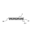
図6は、室内側パネル3の壁側(図1における右側或いは壁8側)、すなわち壁側パネル4との隙間S側、の表面を示している。室内側パネル3の壁側表面には、ペルチェ素子31が貼り付けられている。図6の例では、20枚のペルチェ素子31が貼り付けられている。
図6では明確に示していないが、全てのペルチェ素子31は、前記ラインLs1(図1参照)によって、リモコン10及び図示しない電源と接続されている。
FIG. 6 shows the surface of the
Although not clearly shown in FIG. 6, all the
図7は、図6のX-X断面矢視を示している。図7において、各ペルチェ素子31の表面側には複数のフィン31fが形成されている。フィンを形成することによりペルチェ素子31の表面積が増加し、ペルチェ素子31の放熱量或いは熱吸収量を増加するためである。ペルチェ素子31のフィン31fの周囲は、コーティング材32で被覆されており、結露水による腐食を防止している。
図示は省略しているが、壁側パネル4においても、隙間S側(図1の左側)の表面に、ペルチェ素子31が貼り付けられている。そして、各ペルチェ素子31の表面側には複数のフィン31fが形成されている。
FIG. 7 shows an XX section arrow view of FIG. In FIG. 7, a plurality of fins 31 f are formed on the surface side of each
Although illustration is omitted, also in the wall side panel 4, the
パネル3、4間にペルチェ素子31を貼り付けることにより、冷房時(図1)には、パネル自体が低温(10℃程度)で、パネル間が高温(外気温度:30℃程度)であるため、温度差が発生し、起電力が生じる。
例えば、室内側パネル3のペルチェ素子31で発生した起電力を、壁側パネル4のペルチェ素子に供給し、壁側パネル4のペルチェ素子によって壁側パネル4における熱を吸収して、冷房の補助作用を行うことが可能である。
また、室内側パネル3及び壁側パネル4におけるペルチェ素子31における起電力を、間接照明の電源として利用することもできる。
By attaching the
For example, the electromotive force generated in the
Moreover, the electromotive force in the
図1において、パネル3、4の下方には、結露水の受け皿20が設置されている。
受け皿20の底部には、垂直管21が受け皿20と一体に形成されている。垂直管21の下端には、水平管部22が形成されている。水平管部22は、給気口82に設けたプラグ部材83を貫通するように構成されている。水平管部22の先端には図示しないホース等が接続可能であり、当該ホース等を介して、受け皿20に溜まる結露水を室外(戸外)に排出できるように構成されている。
或いは、給気口82は室外(図1では右側)に向かって下り勾配が形成し、水平管部22の先端から排出された結露水が、給気口82から壁8の外部へ排出できるように構成しても良い。
In FIG. 1, a
A vertical tube 21 is formed integrally with the
Alternatively, the
図1における矢印Fahは、室外からの空気の流れを示している。上述したように、図1の冷房運転では、室外からの空気は冷却されるため、室内側パネル3と壁側パネル4との隙間Sを下降している。
室外から給気口81を経由して流入した空気(Fah)は、壁側パネル4の通気口47を通過し、室内側パネル3と壁側パネル4との隙間Sを下方に向かって流過し、室内50に流入する。空気の流れFahは、隙間Sを流過する際に、パネル3、4内のパイプLa、Lbを流過する冷水が保有する冷熱によって冷却される。
一体型ラジエーター2によって冷やされた冷気が、空調するべき室内(図1において、ラジエーター2よりも左側の空間)に流入する。
An arrow Fah in FIG. 1 indicates the flow of air from the outside. As described above, in the cooling operation of FIG. 1, since the air from the outside is cooled, the gap S between the
The air (Fah) that has flowed in from the outdoor side through the
The cold air cooled by the
図5を参照して、暖房時について説明する。
図5において、壁8に形成された給気口81、82には、それぞれ、給気ファン89、89が介装されている。図1では、給気ファン89、89の図示は省略している。
The heating will be described with reference to FIG.
In FIG. 5, air supply fans 89 and 89 are interposed in the
前述したように、一体型ラジエーター2は、図5で示す位置(暖房時の位置)は、図1で示す位置(冷房時の位置)に対して、180°回転した位置となっている。そして、壁側パネル4の通気口47は、壁8の下側の給気口82と整合した位置となっている。この際、給気口81はシャッター87によって閉塞されている。シャッター87は、図5及び図9では図示の簡略化のため、点線で表現されている。なお図5及び図9において、下方の給気口82のシャッター87は開放状態となっているが、上方の給気口81のシャッター87は閉鎖状態となっている。
室外からの空気は、給気ファン89によって、矢印(空気の流れ)Facで示す様に、給気口82及び通気口47を経由して、パネル3、4間の隙間Sを垂直方向上方へ流過する。そして、隙間Sの上方端部から空調をするべき室内50に流入する。
矢印Facで示す空気は、隙間Sを流過する際に、パネル3、4内のパイプLa、Lbを流過する温水が保有する熱が投入され、加熱して室内50に流入する。
As described above, in the
As shown by the arrow (air flow) Fac, the air from the outside passes through the
When the air indicated by the arrow Fac flows through the gap S, the heat held by the hot water flowing through the pipes La and Lb in the
図8は、図1〜図7で示す実施形態の変形例を示している。ここで、図8は、冷房運転をしている状態を示している。
図8において、給気口81にはフィルタ85が設けられ、フィルタ85は芳香材を包含している。そのため、外気がフィルタ85、一体形ラジエーター2を介して空調するべき室内50に流入した際に、フィルタ85に包含された芳香材が除放する芳香を、室内50に供給する。
明確には図示されていないが、フィルタ85に活性炭を包含し、外気に含まれる異臭源となる異物を吸着、除去して、室内の空気を清浄化するように構成しても良い。これにより、室内環境が向上される。
FIG. 8 shows a modification of the embodiment shown in FIGS. Here, FIG. 8 shows a state in which the cooling operation is performed.
In FIG. 8, the
Although not clearly shown, activated carbon may be included in the
図8で示すように、壁8の給気口81、82の各々にシャッター87を設けることが可能である。シャッター87(図8において、実線で示す下方のシャッター87)を閉鎖することにより、空気を取り入れていない側の給気口(図8では下方の給気口82)から、外気が流入しない様にするためである。この場合、外気を取り入れる側の給気口(図8では上方の給気口81)のシャッター87(図8において、点線で示す上方のシャッター87)は開放して、冷却するべき外気の供給は確保する。
As shown in FIG. 8, a
図8において、室内側パネル3と壁側パネル4との隙間Sの上方には、空気循環用のファン40が設けられている。
ファン40は、正転、逆転が可能であり、正転時には、室内側パネル3と壁側パネル4との隙間Sを流れる空気を下方へ降下し、逆転時には隙間Sを流れる空気を上方へ上昇させる。そして、暖房時(図示を省略)には加熱された空気を下方へ移動せしめ、冷房時(図8)には冷却された空気を上方へ移動させる様に回転する。これにより、加熱された空気(暖房時)或いは冷却された空気(冷房時)を、室内50で良好に循環させることが出来る。すなわち、ファン40により、暖房時には加熱された空気を一端下方へ降下せしめ、冷房時には冷却された空気を一端上方へ上昇させることにより、加熱或いは冷却された空気を、自然対流に比較して、より積極的に空調をするべき空間(室内空間50)内で循環させることが出来る。
In FIG. 8, an
The
図8で示す変形例においても、室内側パネル3及び壁側パネル4の位置を、パネル支持用アーム7により、回転軸9に対して180°回動して、上下方向について移動することが可能である。
図8で示す様に、室内側パネル3及び壁側パネル4の位置が、回転軸9に対して上方にある場合は、冷房を行って、冷却された空気を一端上方へ上昇させるためことが好ましい。一方、図9で示す様に、室内側パネル3及び壁側パネル4の位置が、回転軸9に対して下方にある場合は、暖房を行って、加熱された空気を一端下方へ降下せしめるのが好ましい。
Also in the modified example shown in FIG. 8, the positions of the
As shown in FIG. 8, when the positions of the
図9は、さらに別の変形例を示している。ここで、図9では、暖房運転時を示している。
図9において、一体型ラジエーター2の上方には、加湿用の水入れ60が設置されている。この水入れ60に水を入れて、暖房時において適宜蒸発させることにより、室内が乾燥し過ぎない様にするためである。
図9の変形例におけるそれ以外の構成及び作用効果は、図5と同様である。
FIG. 9 shows still another modification. Here, FIG. 9 shows the heating operation.
In FIG. 9, a
Other configurations and operational effects in the modified example of FIG. 9 are the same as those in FIG.
図示の実施形態によれば、暖房の場合は、図5で示すように、室内側パネル3及び壁側パネル4を回転軸9に対して下側に位置させて、ドラフトにより加熱された暖気を上昇させる。
一方、冷房の場合は、図1で示すように、室内側パネル3及び壁側パネル4を回転軸9に対して上側に位置させて、コールドドラフトにより冷気を下降させる。
According to the illustrated embodiment, in the case of heating, as shown in FIG. 5, the
On the other hand, in the case of cooling, as shown in FIG. 1, the
室内側パネル3の壁側パネル4側(図1では右側)の表面、壁側パネル4の室内側パネル3側(図1では左側)の表面には、図6で示したように、ペルチェ素子31が貼着されている。
ペルチェ素子31がパネル3、4内の温水(或いは冷水)とパネル3と4の間を流れる空気との温度差に晒されることにより、起電力が発生する。
その起電力を、夜間用の間接照明6を点灯に利用することにより、省エネルギーの要請に応えることができる。
As shown in FIG. 6, a Peltier element is formed on the surface of the
When the
By utilizing the electromotive force for lighting the indirect illumination 6 for nighttime, it is possible to meet the demand for energy saving.
ペルチェ素子31には、電流を流すと発熱或いは吸熱を行う性質があり、ペルチェ素子31に電流を流す事により、パネル3と4の間を流れる空気を加熱(ペルチェ素子31を発熱)し、或いは、冷却(ペルチェ素子により吸熱)することができる。これにより、空調の補助を行う事もできる。
The
明確には図示されていないが、図示の実施形態に係る一体型ラジエーター2において、温水による暖房が不十分な場合には、図示しない電源からペルチェ素子31に電流を流して発熱させ、パネル3と4の間を流れる空気を加熱することができる。
そして、冷水による冷房が不十分な場合には、図示しない電源からペルチェ素子31に逆方向に電流を流して、パネル3と4の間を流れる空気から吸熱することができる。
Although not clearly illustrated, in the
When cooling with cold water is insufficient, a current is supplied from a power source (not shown) to the
これに加えて、室内側パネル3側に貼着されたペルチェ素子31に対しては、電流を流して発熱(暖房)或いは吸熱(冷房)せしめて空調の補助を行う。一方、壁側パネル4に対しては、パネル3と4の間を流れる空気とパネル4に供給される温水(暖房時)或いは冷水(冷房時)との温度差により、ペルチェ素子31で発電を行い、その発電電力を照明その他に利用することも可能である。
換言すれば、空調の補助に用いる室内側パネル3側に貼着されたペルチェ素子31には電流を流し、発電に用いる壁側パネル4に貼着されたペルチェ素子31は温度差に晒すのである。
「温度差」なる文言は、パネル3と4の間を流れる空気と、パネル4に供給される温水或いは冷水との温度差を意味している。
In addition to this, the
In other words, an electric current is passed through the
The term “temperature difference” means a temperature difference between the air flowing between the
ここでペルチェ素子は、温度差があるほど発電効率が良好となる。そして、給気口81を介してパネル3及び4間に供給される外気は一定の温度を保つ。換言すれば、パネルによる加熱或いは冷却を長時間行っても外気温度は一定である。そのため、ペルチェ素子31の発電効率は一定に保たれる。
Here, the power generation efficiency of the Peltier element becomes better as there is a temperature difference. The outside air supplied between the
ここで、冷房時において、例えば、パネルの温水入り温度は10℃前後であり、外気が30℃前後であるとすれば、温度差(約20℃)である。すなわち、大きな温度差は得られない。
一方、暖房時においては、温水入り温度は通常70℃程度であり、外気が例えば10℃であれば、温度差は約60℃となり、比較的大きな温度差が得られる。
係る温度差を考慮すると、大きな温度差が得られる暖房時にはペルチェ素子31で発電を行い、温度差が比較的小さい冷房時には、ペルチェ素子31に電流を供給して、パネル3及び4間に供給される空気を冷却する補助を行わせる(冷房運転を補助する)のが好適である。
Here, at the time of cooling, for example, if the temperature of the panel is about 10 ° C. and the outside air is about 30 ° C., it is a temperature difference (about 20 ° C.). That is, a large temperature difference cannot be obtained.
On the other hand, during heating, the temperature with warm water is usually about 70 ° C. If the outside air is, for example, 10 ° C., the temperature difference is about 60 ° C., and a relatively large temperature difference is obtained.
Considering such a temperature difference, power is generated by the
図示の実施形態によれば、給気口81または82から取り入れられた外気は、暖められ或いは冷やされて、空調をするべき室内50に流入するため、空調室内50を局所的に過剰に暖房したり、冷房したりすることが無い。そのため、人体にやさしい空調を実現することが出来る。
According to the illustrated embodiment, since the outside air taken in from the
さらに、図示の実施形態は、機械要素が少ないため、装置全体が安価である。したがって、複数設置したとしても、建造物全体を空調する方式に比べて価格的に有利であり、故障の確率も低い。 In addition, the illustrated embodiment has fewer machine elements, so the entire apparatus is inexpensive. Therefore, even if a plurality of units are installed, the price is more advantageous than the method of air-conditioning the entire building, and the probability of failure is low.
図示の実施形態はあくまでも例示であり、本発明の技術的範囲を限定する趣旨の記述ではない旨を付記する。 It should be noted that the illustrated embodiment is merely an example, and is not a description to limit the technical scope of the present invention.
1・・・熱源機
2・・・一体型ラジエーター
3・・・室内側パネル
4・・・壁側パネル
5・・・化粧板
6・・・間接照明装置
7・・・パネル支持用アーム
8・・・壁
9・・・回転軸
10・・・ラジエーター用リモートコントローラ/リモコン
20・・・結露水受け皿
45・・・断熱材
81、82・・・給気口
85・・・フィルタ
89・・・ファン
DESCRIPTION OF
Claims (2)
Priority Applications (1)
| Application Number | Priority Date | Filing Date | Title |
|---|---|---|---|
| JP2007263351A JP4974369B2 (en) | 2007-10-09 | 2007-10-09 | Air conditioner |
Applications Claiming Priority (1)
| Application Number | Priority Date | Filing Date | Title |
|---|---|---|---|
| JP2007263351A JP4974369B2 (en) | 2007-10-09 | 2007-10-09 | Air conditioner |
Publications (2)
| Publication Number | Publication Date |
|---|---|
| JP2009092310A JP2009092310A (en) | 2009-04-30 |
| JP4974369B2 true JP4974369B2 (en) | 2012-07-11 |
Family
ID=40664463
Family Applications (1)
| Application Number | Title | Priority Date | Filing Date |
|---|---|---|---|
| JP2007263351A Expired - Fee Related JP4974369B2 (en) | 2007-10-09 | 2007-10-09 | Air conditioner |
Country Status (1)
| Country | Link |
|---|---|
| JP (1) | JP4974369B2 (en) |
Families Citing this family (5)
| Publication number | Priority date | Publication date | Assignee | Title |
|---|---|---|---|---|
| EP2631584B1 (en) * | 2012-02-22 | 2014-04-09 | Zehnder Verkaufs- und Verwaltungs AG | Heater |
| WO2013145069A1 (en) * | 2012-03-26 | 2013-10-03 | 三洋電機株式会社 | Power control device |
| JP6362905B2 (en) * | 2014-04-04 | 2018-07-25 | 国立大学法人 東京大学 | Equipment unit |
| JP2017083096A (en) * | 2015-10-29 | 2017-05-18 | Cks株式会社 | Cooling/heating device with illumination |
| WO2019172859A1 (en) * | 2018-03-09 | 2019-09-12 | Rema Yapi Ve Mi̇marlik Anoni̇m Şi̇rketi̇ | Smart ventilation system |
Family Cites Families (7)
| Publication number | Priority date | Publication date | Assignee | Title |
|---|---|---|---|---|
| JPH04177024A (en) * | 1990-11-09 | 1992-06-24 | Daikin Ind Ltd | Radiation type air conditioner using electronic freezing element |
| JP2916115B2 (en) * | 1997-01-31 | 1999-07-05 | ナショナル住宅産業株式会社 | Heating and ventilation structure |
| JPH1122993A (en) * | 1997-06-27 | 1999-01-26 | Hazama Gumi Ltd | Wall surface warming apparatus |
| JPH1137493A (en) * | 1997-07-18 | 1999-02-12 | Eidai Co Ltd | Cooling system, heating system and both cooling and heating systems |
| JP4145106B2 (en) * | 2002-09-10 | 2008-09-03 | シャープ株式会社 | Air conditioner |
| JP4841240B2 (en) * | 2005-12-13 | 2011-12-21 | Necライティング株式会社 | Lighting device |
| JP2007183049A (en) * | 2006-01-10 | 2007-07-19 | Tadashi Miyamoto | Air conditioning system |
-
2007
- 2007-10-09 JP JP2007263351A patent/JP4974369B2/en not_active Expired - Fee Related
Also Published As
| Publication number | Publication date |
|---|---|
| JP2009092310A (en) | 2009-04-30 |
Similar Documents
| Publication | Publication Date | Title |
|---|---|---|
| JP4974369B2 (en) | Air conditioner | |
| JP6231441B2 (en) | Radiant air conditioning system | |
| KR100512040B1 (en) | Cold and heat device for combined dehumidify | |
| JP2013509559A (en) | Apparatus for air conditioning a room and heat pump assembly for use in the apparatus | |
| JP4648462B2 (en) | Ventilation air conditioning system and unit building | |
| JP2016196974A (en) | Radiant air conditioning system | |
| JP5926711B2 (en) | Heating system | |
| JP2008075922A (en) | Humidity-conditioning cooling/heating device and spatial structure using the same | |
| JP4995746B2 (en) | Building ventilation system | |
| JP6811542B2 (en) | Radiant heating and cooling system | |
| JP2005273970A (en) | Air conditioning system of building | |
| JP4605759B2 (en) | Indoor air conditioning system for buildings | |
| JP2010091243A (en) | Energy saving ventilation system and energy saving building having the same | |
| JP5802039B2 (en) | Ceiling radiant cooling system by cold storage / cooling and moisture storage / humidification | |
| JP7018627B2 (en) | Air conditioning equipment | |
| JP2017172886A (en) | Air conditioning system | |
| JP2011002104A (en) | Air conditioning system | |
| JP2017180905A (en) | Radiation air-conditioning device | |
| JP3123276U (en) | Housing structure | |
| JPH1054584A (en) | Cooling and heating structure for building | |
| JP6708432B2 (en) | Radiant cooling/heating system and radiant cooling/heating method | |
| JP2007127294A (en) | Solar-based heat storage ceiling structure | |
| JP2005163369A (en) | Ventilation device for dwelling house | |
| JP2006029733A (en) | Both cold and hot season ventilating system utilizing heat collecting duct | |
| JP6389550B2 (en) | Radiant air conditioning method |
Legal Events
| Date | Code | Title | Description |
|---|---|---|---|
| A621 | Written request for application examination |
Free format text: JAPANESE INTERMEDIATE CODE: A621 Effective date: 20100311 |
|
| A977 | Report on retrieval |
Free format text: JAPANESE INTERMEDIATE CODE: A971007 Effective date: 20110922 |
|
| A131 | Notification of reasons for refusal |
Free format text: JAPANESE INTERMEDIATE CODE: A131 Effective date: 20111006 |
|
| A521 | Request for written amendment filed |
Free format text: JAPANESE INTERMEDIATE CODE: A523 Effective date: 20111028 |
|
| TRDD | Decision of grant or rejection written | ||
| A01 | Written decision to grant a patent or to grant a registration (utility model) |
Free format text: JAPANESE INTERMEDIATE CODE: A01 Effective date: 20120406 |
|
| A01 | Written decision to grant a patent or to grant a registration (utility model) |
Free format text: JAPANESE INTERMEDIATE CODE: A01 |
|
| A61 | First payment of annual fees (during grant procedure) |
Free format text: JAPANESE INTERMEDIATE CODE: A61 Effective date: 20120409 |
|
| R150 | Certificate of patent or registration of utility model |
Free format text: JAPANESE INTERMEDIATE CODE: R150 |
|
| FPAY | Renewal fee payment (event date is renewal date of database) |
Free format text: PAYMENT UNTIL: 20150420 Year of fee payment: 3 |
|
| LAPS | Cancellation because of no payment of annual fees |