JP4970224B2 - Semiconductor integrated circuit - Google Patents
Semiconductor integrated circuit Download PDFInfo
- Publication number
- JP4970224B2 JP4970224B2 JP2007309955A JP2007309955A JP4970224B2 JP 4970224 B2 JP4970224 B2 JP 4970224B2 JP 2007309955 A JP2007309955 A JP 2007309955A JP 2007309955 A JP2007309955 A JP 2007309955A JP 4970224 B2 JP4970224 B2 JP 4970224B2
- Authority
- JP
- Japan
- Prior art keywords
- switch
- operational amplifier
- input terminal
- analog
- converter
- Prior art date
- Legal status (The legal status is an assumption and is not a legal conclusion. Google has not performed a legal analysis and makes no representation as to the accuracy of the status listed.)
- Expired - Fee Related
Links
Images


Classifications
-
- H—ELECTRICITY
- H03—ELECTRONIC CIRCUITRY
- H03F—AMPLIFIERS
- H03F3/00—Amplifiers with only discharge tubes or only semiconductor devices as amplifying elements
- H03F3/45—Differential amplifiers
- H03F3/45071—Differential amplifiers with semiconductor devices only
- H03F3/45076—Differential amplifiers with semiconductor devices only characterised by the way of implementation of the active amplifying circuit in the differential amplifier
- H03F3/45179—Differential amplifiers with semiconductor devices only characterised by the way of implementation of the active amplifying circuit in the differential amplifier using MOSFET transistors as the active amplifying circuit
- H03F3/45183—Long tailed pairs
- H03F3/45192—Folded cascode stages
-
- H—ELECTRICITY
- H03—ELECTRONIC CIRCUITRY
- H03F—AMPLIFIERS
- H03F3/00—Amplifiers with only discharge tubes or only semiconductor devices as amplifying elements
- H03F3/45—Differential amplifiers
- H03F3/45071—Differential amplifiers with semiconductor devices only
- H03F3/45076—Differential amplifiers with semiconductor devices only characterised by the way of implementation of the active amplifying circuit in the differential amplifier
- H03F3/45475—Differential amplifiers with semiconductor devices only characterised by the way of implementation of the active amplifying circuit in the differential amplifier using IC blocks as the active amplifying circuit
-
- H—ELECTRICITY
- H03—ELECTRONIC CIRCUITRY
- H03F—AMPLIFIERS
- H03F3/00—Amplifiers with only discharge tubes or only semiconductor devices as amplifying elements
- H03F3/45—Differential amplifiers
- H03F3/45071—Differential amplifiers with semiconductor devices only
- H03F3/45479—Differential amplifiers with semiconductor devices only characterised by the way of common mode signal rejection
- H03F3/45632—Differential amplifiers with semiconductor devices only characterised by the way of common mode signal rejection in differential amplifiers with FET transistors as the active amplifying circuit
- H03F3/45744—Differential amplifiers with semiconductor devices only characterised by the way of common mode signal rejection in differential amplifiers with FET transistors as the active amplifying circuit by offset reduction
- H03F3/45748—Differential amplifiers with semiconductor devices only characterised by the way of common mode signal rejection in differential amplifiers with FET transistors as the active amplifying circuit by offset reduction by using a feedback circuit
- H03F3/45753—Differential amplifiers with semiconductor devices only characterised by the way of common mode signal rejection in differential amplifiers with FET transistors as the active amplifying circuit by offset reduction by using a feedback circuit using switching means, e.g. sample and hold
-
- H—ELECTRICITY
- H03—ELECTRONIC CIRCUITRY
- H03F—AMPLIFIERS
- H03F3/00—Amplifiers with only discharge tubes or only semiconductor devices as amplifying elements
- H03F3/45—Differential amplifiers
- H03F3/45071—Differential amplifiers with semiconductor devices only
- H03F3/45479—Differential amplifiers with semiconductor devices only characterised by the way of common mode signal rejection
- H03F3/45928—Differential amplifiers with semiconductor devices only characterised by the way of common mode signal rejection using IC blocks as the active amplifying circuit
- H03F3/45968—Differential amplifiers with semiconductor devices only characterised by the way of common mode signal rejection using IC blocks as the active amplifying circuit by offset reduction
- H03F3/45973—Differential amplifiers with semiconductor devices only characterised by the way of common mode signal rejection using IC blocks as the active amplifying circuit by offset reduction by using a feedback circuit
- H03F3/45977—Differential amplifiers with semiconductor devices only characterised by the way of common mode signal rejection using IC blocks as the active amplifying circuit by offset reduction by using a feedback circuit using switching means, e.g. sample and hold
-
- H—ELECTRICITY
- H03—ELECTRONIC CIRCUITRY
- H03M—CODING; DECODING; CODE CONVERSION IN GENERAL
- H03M1/00—Analogue/digital conversion; Digital/analogue conversion
- H03M1/06—Continuously compensating for, or preventing, undesired influence of physical parameters
- H03M1/0617—Continuously compensating for, or preventing, undesired influence of physical parameters characterised by the use of methods or means not specific to a particular type of detrimental influence
- H03M1/0634—Continuously compensating for, or preventing, undesired influence of physical parameters characterised by the use of methods or means not specific to a particular type of detrimental influence by averaging out the errors, e.g. using sliding scale
- H03M1/0656—Continuously compensating for, or preventing, undesired influence of physical parameters characterised by the use of methods or means not specific to a particular type of detrimental influence by averaging out the errors, e.g. using sliding scale in the time domain, e.g. using intended jitter as a dither signal
- H03M1/066—Continuously compensating for, or preventing, undesired influence of physical parameters characterised by the use of methods or means not specific to a particular type of detrimental influence by averaging out the errors, e.g. using sliding scale in the time domain, e.g. using intended jitter as a dither signal by continuously permuting the elements used, i.e. dynamic element matching
- H03M1/0663—Continuously compensating for, or preventing, undesired influence of physical parameters characterised by the use of methods or means not specific to a particular type of detrimental influence by averaging out the errors, e.g. using sliding scale in the time domain, e.g. using intended jitter as a dither signal by continuously permuting the elements used, i.e. dynamic element matching using clocked averaging
-
- H—ELECTRICITY
- H03—ELECTRONIC CIRCUITRY
- H03M—CODING; DECODING; CODE CONVERSION IN GENERAL
- H03M3/00—Conversion of analogue values to or from differential modulation
- H03M3/30—Delta-sigma modulation
- H03M3/322—Continuously compensating for, or preventing, undesired influence of physical parameters
- H03M3/324—Continuously compensating for, or preventing, undesired influence of physical parameters characterised by means or methods for compensating or preventing more than one type of error at a time, e.g. by synchronisation or using a ratiometric arrangement
- H03M3/326—Continuously compensating for, or preventing, undesired influence of physical parameters characterised by means or methods for compensating or preventing more than one type of error at a time, e.g. by synchronisation or using a ratiometric arrangement by averaging out the errors
- H03M3/338—Continuously compensating for, or preventing, undesired influence of physical parameters characterised by means or methods for compensating or preventing more than one type of error at a time, e.g. by synchronisation or using a ratiometric arrangement by averaging out the errors by permutation in the time domain, e.g. dynamic element matching
- H03M3/342—Continuously compensating for, or preventing, undesired influence of physical parameters characterised by means or methods for compensating or preventing more than one type of error at a time, e.g. by synchronisation or using a ratiometric arrangement by averaging out the errors by permutation in the time domain, e.g. dynamic element matching by double sampling, e.g. correlated double sampling
-
- H—ELECTRICITY
- H03—ELECTRONIC CIRCUITRY
- H03F—AMPLIFIERS
- H03F2203/00—Indexing scheme relating to amplifiers with only discharge tubes or only semiconductor devices as amplifying elements covered by H03F3/00
- H03F2203/45—Indexing scheme relating to differential amplifiers
- H03F2203/45138—Two or more differential amplifiers in IC-block form are combined, e.g. measuring amplifiers
-
- H—ELECTRICITY
- H03—ELECTRONIC CIRCUITRY
- H03F—AMPLIFIERS
- H03F2203/00—Indexing scheme relating to amplifiers with only discharge tubes or only semiconductor devices as amplifying elements covered by H03F3/00
- H03F2203/45—Indexing scheme relating to differential amplifiers
- H03F2203/45212—Indexing scheme relating to differential amplifiers the differential amplifier being designed to have a reduced offset
-
- H—ELECTRICITY
- H03—ELECTRONIC CIRCUITRY
- H03F—AMPLIFIERS
- H03F2203/00—Indexing scheme relating to amplifiers with only discharge tubes or only semiconductor devices as amplifying elements covered by H03F3/00
- H03F2203/45—Indexing scheme relating to differential amplifiers
- H03F2203/45726—Indexing scheme relating to differential amplifiers the LC comprising more than one switch, which are not cross coupled
-
- H—ELECTRICITY
- H03—ELECTRONIC CIRCUITRY
- H03M—CODING; DECODING; CODE CONVERSION IN GENERAL
- H03M1/00—Analogue/digital conversion; Digital/analogue conversion
- H03M1/12—Analogue/digital converters
- H03M1/1205—Multiplexed conversion systems
- H03M1/122—Shared using a single converter or a part thereof for multiple channels, e.g. a residue amplifier for multiple stages
- H03M1/1225—Shared using a single converter or a part thereof for multiple channels, e.g. a residue amplifier for multiple stages using time-division multiplexing
-
- H—ELECTRICITY
- H03—ELECTRONIC CIRCUITRY
- H03M—CODING; DECODING; CODE CONVERSION IN GENERAL
- H03M1/00—Analogue/digital conversion; Digital/analogue conversion
- H03M1/12—Analogue/digital converters
- H03M1/34—Analogue value compared with reference values
- H03M1/38—Analogue value compared with reference values sequentially only, e.g. successive approximation type
- H03M1/46—Analogue value compared with reference values sequentially only, e.g. successive approximation type with digital/analogue converter for supplying reference values to converter
Landscapes
- Engineering & Computer Science (AREA)
- Power Engineering (AREA)
- Theoretical Computer Science (AREA)
- Analogue/Digital Conversion (AREA)
- Amplifiers (AREA)
Abstract
Description
本発明は、半導体集積回路に関するもので、特にA/D変換器の入力端子に接続されたサンプリング回路またはマルチプレクサーの演算増幅器の入力オフセット電圧によるアナログ入力信号源インピーダンスでのオフセット誤差電圧を低減するのに有益な技術に関する。 The present invention relates to a semiconductor integrated circuit, and more particularly to reduce an offset error voltage at an analog input signal source impedance due to an input offset voltage of a sampling circuit or an operational amplifier of a multiplexer connected to an input terminal of an A / D converter. Related to useful technology.
高精度と高解像度とが必要とされるシステムでは、下記非特許文献1に記載されているように、複数のアナログ入力信号の1つを選択してアナログ信号をディジタル信号に変換するA/D変換器に供給するためにアナログマルチプレクサーが使用される。このアナログマルチプレクサーの複数のアナログスイッチの一端には複数のアナログ入力信号が供給され、複数のアナログスイッチの他端はバッファアンプの入力に接続され、バッファアンプの出力はサンプル・ホールド回路を介してA/D変換器の入力に接続される。アナログ入力システムのサンプル・ホールド回路の基本機能は、入力信号を捕捉して、引き続くA/D変換器の変換サイクルの間に一定に保持することである。
In a system that requires high accuracy and high resolution, as described in Non-Patent
このサンプル・ホールド回路は、入力バッファアンプとサンプル・ホールドスイッチと保持容量と出力バッファとによって構成されている。サンプル・モードでは、入力信号は入力バッファアンプとオン状態のサンプル・ホールドスイッチとを介して保持容量に保持される。ホールド・モードでは、サンプル・ホールドスイッチはオフ状態に制御されて、保持容量の保持電圧は出力バッファを介してA/D変換器の入力に供給される。 This sample and hold circuit is composed of an input buffer amplifier, a sample and hold switch, a holding capacitor, and an output buffer. In the sample mode, the input signal is held in the holding capacitor via the input buffer amplifier and the ON-state sample / hold switch. In the hold mode, the sample / hold switch is controlled to be in the OFF state, and the holding voltage of the holding capacitor is supplied to the input of the A / D converter via the output buffer.
下記特許文献1には、アナログマルチプレクサーと逐次比較型A/D変換器とを含むマイクロコンピュータが半導体基板に形成された半導体集積回路が記載されている。アナログマルチプレクサーは複数の外部端子の複数のアナログ入力信号を選択して、選択されたアナログ入力信号は逐次比較型A/D変換器のコンパレータの第1入力端子に供給される。コンパレータの出力によって逐次比較レジスタの複数ビット信号が制御され、逐次比較レジスタの複数ビット信号によって局部D/A変換器が制御される。逐次比較レジスタの複数ビット信号の上位8ビット信号と下位2ビットとに応答して、局部D/A変換器から第1比較基準電圧と第2比較基準電圧とがそれぞれ生成される。局部D/A変換器からの第1比較基準電圧と第2比較基準電圧とは、第1演算増幅器と第2演算増幅器とを介してコンパレータの第2入力端子と第3入力端子とにそれぞれ供給される。コンパレータ内部では、第1入力端子と第2入力端子とに選択スイッチの2入力端子が接続され、選択スイッチの出力端子は第1容量の一端に接続され、第3入力端子に第2容量の一端に接続され、第1容量の他端と第2容量の他端とは電圧比較部の入力端子に接続されている。局部D/A変換器では、第1演算増幅器の入出力端子間には第1演算増幅器のオフセット電圧の影響を低減する第1トランスファスイッチが接続され、第2演算増幅器の入出力端子間には第2演算増幅器のオフセット電圧の影響を低減する第2トランスファスイッチが接続されている。
一方、下記非特許文献2には、相関二重サンプリング(CDS;Correlated Double Sampling)を利用した演算増幅器の不完全性の影響を低減する回路技術が記載されている。下記非特許文献2の図29には、第1スイッチ、第2スイッチ、サンプリング容量、演算増幅器、第3スイッチで構成された第1の形式のスイッチト・キャパシタ型のサンプル・ホールド回路が記載されている。入力信号は第1クロック信号で制御される第1スイッチを介してサンプリング容量の一端と第2クロック信号で制御される第2スイッチの一端とに供給され、サンプリング容量の他端は演算増幅器の反転入力端子と第1クロック信号で制御される第3スイッチの一端とに接続されている。演算増幅器の非反転入力端子には接地電位に接続され、演算増幅器の出力端子は第2スイッチの他端と第3スイッチの他端とに接続されている。
On the other hand, Non-Patent
この第1の形式のスイッチト・キャパシタ型のサンプル・ホールド回路は、下記のようにサンプル・モードとホールド・モードの動作を実行する。すなわち、第1クロック信号がハイレベルの期間には入力信号がサンプリング容量を介して演算増幅器の反転入力端子に供給され演算増幅器の反転入力端子と出力端子とが接続されているので、入力信号電圧とオフセット電圧との差電圧がサンプリング容量の両端の間にサンプリングされる。第2クロック信号がハイレベルの期間には、入力信号の供給ノードは演算増幅器の反転入力端子からオープンとされ、サンプリング容量が演算増幅器の反転入力端子と出力端子との間に接続されるので、相関二重サンプリングによってオフセット電圧の影響が低減されたホールド出力信号が得られるとしている。 The switched capacitor type sample and hold circuit of the first type executes the operation in the sample mode and the hold mode as follows. That is, since the input signal is supplied to the inverting input terminal of the operational amplifier through the sampling capacitor and the inverting input terminal and the output terminal of the operational amplifier are connected while the first clock signal is at the high level, the input signal voltage And the offset voltage are sampled across the sampling capacitor. During the period when the second clock signal is at a high level, the input signal supply node is opened from the inverting input terminal of the operational amplifier, and the sampling capacitor is connected between the inverting input terminal and the output terminal of the operational amplifier. The hold output signal in which the influence of the offset voltage is reduced is obtained by correlated double sampling.
また、下記非特許文献3には、相関二重サンプリング(CDS)を利用したスイッチト・キャパシタ型のコンパレータが記載されている。このスイッチト・キャパシタ型のコンパレータは、2入力端子を持つ選択第1スイッチ、サンプリング容量、演算増幅器、第2スイッチを含んでいる。また、このスイッチト・キャパシタ型のコンパレータは、下記のようにサンプル・モードとホールド・電圧比較モードの動作を実行する。すなわち、サンプル・モードでは、入力信号が選択第1スイッチの第1入力端子とサンプリング容量とを介して演算増幅器の反転入力端子に供給され、演算増幅器の反転入力端子と出力端子とが接続されているので、入力信号電圧とオフセット電圧との差電圧がサンプリング容量の両端の間にサンプリングされる。また、ホールド・電圧比較モードでは、接地電圧が選択第1スイッチの第2入力端子とサンプリング容量とを介して演算増幅器の反転入力端子に供給され、演算増幅器の反転入力端子と出力端子との間がオープンとされる。従って、サンプル・モードとホールド・電圧比較モードの動作の間に演算増幅器のオフセット電圧がキャンセルされて、オフセット電圧と入力信号電圧との差に相当する負の入力信号電圧−Vinの正負の符号に応じて、演算増幅器の出力端子から論理判定結果が得られるとしている。
Non-Patent
一方、下記非特許文献4には、下記非特許文献2に記載された第1の形式のスイッチト・キャパシタ型のサンプル・ホールド回路と異なる第2の形式のスイッチト・キャパシタ型のサンプル・ホールド回路が記載されている。この第2の形式のスイッチト・キャパシタ型のサンプル・ホールド回路は、演算増幅器を構成可能な3個の電流源、差動対PチャンネルMOSトランジスタ、2個の負荷NチャンネルMOSトランジスタ、2個のソース接地増幅NチャンネルMOSトランジスタ、7個のスイッチ、負荷容量により構成される。
On the other hand, the following non-patent document 4 describes a switched capacitor type sample and hold circuit of a second type different from the switched capacitor type sample and hold circuit of the first type described in the following
この第2の形式のスイッチト・キャパシタ型のサンプル・ホールド回路のサンプル・モードでは、入力信号が演算増幅器の非反転入力端子に供給され、演算増幅器の出力端子は負荷容量と反転入力端子とに接続される。従って、サンプル・モードの演算増幅器はユニティー・ゲイン(ボルテージフォロワ)で動作するので、非反転入力端子の入力信号のレベルは出力端子の負荷容量にサンプルされる。またホールド・モードでは、負荷容量は演算増幅器の非反転入力端子に供給され、演算増幅器の出力端子は出力と反転入力端子とに接続される。従って、ホールド・モードでも演算増幅器はユニティー・ゲイン(ボルテージフォロワ)で動作するので、非反転入力端子の負荷容量のサンプルレベルは出力にホールドされる。また、サンプル・モードとホールド・モードとで演算増幅器の非反転入力端子と反転入力端子としてそれぞれ機能するトランジスタは、差動対PチャンネルMOSトランジスタで左右交代する。更に、サンプル・モードとホールド・モードとで演算増幅器の2個の負荷NチャンネルMOSトランジスタのカレントミラーの入力トランジスタと出力トランジスタとしてそれぞれ機能するトランジスタは、2個の負荷NチャンネルMOSトランジスタで左右交代する。また、サンプル・モードとホールド・モードとで演算増幅器の出力素子としてそれぞれ機能するトランジスタは、2個のソース接地増幅NチャンネルMOSトランジスタで左右交代する。以上のトランジスタの左右交代によって、演算増幅器を構成するトランジスタのミスマッチによるオフセット電圧の影響を低減することができる。 In the sample mode of the switched capacitor type sample and hold circuit of the second type, the input signal is supplied to the non-inverting input terminal of the operational amplifier, and the output terminal of the operational amplifier is connected to the load capacitance and the inverting input terminal. Connected. Therefore, since the operational amplifier in the sample mode operates with unity gain (voltage follower), the level of the input signal at the non-inverting input terminal is sampled by the load capacitance at the output terminal. In the hold mode, the load capacitance is supplied to the non-inverting input terminal of the operational amplifier, and the output terminal of the operational amplifier is connected to the output and the inverting input terminal. Therefore, since the operational amplifier operates with unity gain (voltage follower) even in the hold mode, the sample level of the load capacitance at the non-inverting input terminal is held at the output. In addition, the transistors functioning as the non-inverting input terminal and the inverting input terminal of the operational amplifier in the sample mode and the hold mode are alternately switched by the differential pair P-channel MOS transistors. Further, in the sample mode and the hold mode, the transistors functioning as the input transistor and the output transistor of the current mirror of the two load N-channel MOS transistors of the operational amplifier are alternated by the two load N-channel MOS transistors. . The transistors functioning as the output elements of the operational amplifier in the sample mode and the hold mode are alternated by two source-grounded amplification N-channel MOS transistors. By the left-right alternation of the above transistors, it is possible to reduce the influence of the offset voltage due to the mismatch of the transistors constituting the operational amplifier.
また下記特許文献2には、特殊な巡回型A/D変換器の内部の増幅器のオフセット電圧によるA/D変換結果への影響を低減するために、増幅器の差動入力と差動出力との間の2個の帰還容量をクロスカップル接続とストレート接続とに切り換える切換スイッチを使用することが記載されている。
Further, in
一方、下記非特許文献5には、コモン・モード入力電圧の変化に対して並列接続されたNチャンネル差動MOSトランジスタとPチャンネル差動MOSトランジスタとからなるレイル・ツー・レイル入力回路の相互コンダクタンスgmを一定とするgm制御回路が記載されている。このgm制御回路は、電流スイッチPチャンネルMOS、電流スイッチNチャンネルMOS、カレントミラーNチャンネルMOS、カレントミラーPチャンネルMOSから構成されている。 On the other hand, the following non-patent document 5 discloses a mutual conductance of a rail-to-rail input circuit composed of an N-channel differential MOS transistor and a P-channel differential MOS transistor connected in parallel with a change in common mode input voltage. A gm control circuit that makes gm constant is described. This gm control circuit includes a current switch P-channel MOS, a current switch N-channel MOS, a current mirror N-channel MOS, and a current mirror P-channel MOS.
一対のPチャンネルMOSトランジスタは差動入力信号からハイレベル・コモン・モード電圧を生成して、ハイレベル・コモン・モード電圧はゲートに直流バイアス電圧が供給された電流スイッチPチャンネルMOSのソースに供給される。電流スイッチPチャンネルMOSのドレインに接続されたカレントミラーNチャンネルMOSにより、Nチャンネル差動MOSトランジスタのソースのバイアス電流が電流スイッチPチャンネルMOSのドレイン電流に比例して制御される。一対のNチャンネルMOSトランジスタは差動入力信号からローレベル・コモン・モード電圧を生成して、ローレベル・コモン・モード電圧はゲートに直流バイアス電圧が供給された電流スイッチNチャンネルMOSのソースに供給される。電流スイッチNチャンネルMOSのドレインに接続されたカレントミラーPチャンネルMOSにより、Pチャンネル差動MOSトランジスタのソースのバイアス電流が電流スイッチNチャンネルMOSのドレイン電流に比例して制御される。 A pair of P-channel MOS transistors generate a high-level common mode voltage from the differential input signal, and the high-level common mode voltage is supplied to the source of a current switch P-channel MOS whose gate is supplied with a DC bias voltage. Is done. The current mirror N-channel MOS connected to the drain of the current switch P-channel MOS controls the bias current of the source of the N-channel differential MOS transistor in proportion to the drain current of the current switch P-channel MOS. A pair of N-channel MOS transistors generate a low-level common mode voltage from the differential input signal, and the low-level common mode voltage is supplied to the source of a current switch N-channel MOS whose gate is supplied with a DC bias voltage. Is done. The bias current at the source of the P-channel differential MOS transistor is controlled in proportion to the drain current of the current switch N-channel MOS by the current mirror P-channel MOS connected to the drain of the current switch N-channel MOS.
本発明者等は本発明に先立って、自動車に搭載されるマイクロコンピュータの開発に従事した。この車載用マイクロコンピュータは、上記特許文献1に記載されたように半導体集積回路の半導体基板にアナログマルチプレクサーと逐次比較型A/D変換器とを含むものである。
Prior to the present invention, the present inventors engaged in the development of a microcomputer mounted on an automobile. This in-vehicle microcomputer includes an analog multiplexer and a successive approximation A / D converter on a semiconductor substrate of a semiconductor integrated circuit as described in
この開発に先立って、本発明者等は上記背景技術に記載された種々のコンパレータやサンプル・ホールド回路に関して検討を行った。 Prior to this development, the present inventors examined various comparators and sample-and-hold circuits described in the background art.
まず、上記非特許文献2に記載された相関二重サンプリングを利用した第1の形式のサンプル・ホールド回路を使用して、演算増幅器の反転入力端子と出力端子との間が接続された状態で、演算増幅器の反転入力端子に接続されたサンプリング容量に入力信号をサンプリングする。その後、演算増幅器の反転入力端子と出力端子との間をオープンとした状態で、演算増幅器の反転入力端子に接続されたサンプリング容量に比較基準電圧を供給する。それにより、上記非特許文献3に記載された相関二重サンプリングを利用したスイッチト・キャパシタ型のコンパレータのサンプル・モードとホールド・電圧比較モードと同様な動作を実現できる。この際、演算増幅器のオフセット電圧がキャンセルされて、比較基準電圧と入力信号電圧との差電圧の正負の符号に応じて、演算増幅器の出力端子から論理判定結果が得られる。
First, in the state where the inverting input terminal and the output terminal of the operational amplifier are connected using the first type sample and hold circuit using the correlated double sampling described in
また、上記非特許文献4に記載された第2の形式のスイッチト・キャパシタ型のサンプル・ホールド回路は、トランジスタの左右交代によって演算増幅器を構成するトランジスタのミスマッチによるオフセット電圧の影響を低減することができる。しかし、この第2の形式のスイッチト・キャパシタ型のサンプル・ホールド回路は、上記非特許文献2に記載の第1の形式のサンプル・ホールド回路のように上記非特許文献3に記載のスイッチト・キャパシタ型のコンパレータのホールド・電圧比較モードと同様な動作を実現することができない。
Further, the switched capacitor type sample and hold circuit of the second type described in Non-Patent Document 4 described above reduces the influence of the offset voltage due to the mismatch of the transistors constituting the operational amplifier by the left and right change of the transistors. Can do. However, the switched capacitor type sample and hold circuit of the second type is similar to the switched type of sample and hold circuit of the first type described in
更に、上記特許文献2に記載された巡回型A/D変換器は、増幅器の差動入力と差動出力との間の2個の帰還容量のクロスカップル接続とストレート接続とを切り換えことにより、内部の増幅器のオフセット電圧によるA/D変換結果への影響を低減することができる。しかし、この巡回型A/D変換器は、極めて特殊なA/D変換器であるので、上記特許文献1に記載されたような逐次比較型A/D変換器に適用することはできない。
Furthermore, the cyclic A / D converter described in the above-mentioned
図1は、本発明に先立って本発明者等によって検討されたモノリシック半導体集積回路を示す図である。このモノリシック半導体集積回路は、上記特許文献1に記載されたように半導体集積回路の半導体基板にアナログマルチプレクサーと逐次比較型A/D変換器とを含む車載用マイクロコンピュータである。
FIG. 1 is a diagram showing a monolithic semiconductor integrated circuit studied by the present inventors prior to the present invention. This monolithic semiconductor integrated circuit is an in-vehicle microcomputer that includes an analog multiplexer and a successive approximation A / D converter on a semiconductor substrate of a semiconductor integrated circuit as described in
同図に示すように、半導体集積回路の半導体チップは、アナログ回路部Analog_Cirと、ディジタル回路部Digital_Cirと、中央処理ユニット(CPU;図示せず)とを含んでいる。 As shown in the figure, the semiconductor chip of the semiconductor integrated circuit includes an analog circuit unit Analog_Cir, a digital circuit unit Digital_Cir, and a central processing unit (CPU; not shown).
アナログ回路部Analog_Cirは、8チャンネルのアナログ入力端子AN0、AN1、AN2…AN7と1チャンネルのアナログ出力のマルチプレクサーMPXと、10ビットの逐次比較型A/D変換器10bit A/D_Convとを含んでいる。また、アナログ回路部Analog_Cirは、10ビットの局部D/A変換器 10bit Local D/A_Convを含んでいる。 The analog circuit unit Analog_Cir includes 8-channel analog input terminals AN0, AN1, AN2,... AN7, a 1-channel analog output multiplexer MPX, and a 10-bit successive approximation A / D converter 10bit A / D_Conv. Yes. The analog circuit unit Analog_Cir includes a 10-bit local D / A converter 10-bit Local D / A_Conv.
ディジタル回路部Digital_Cirは、コントロール回路Control_Cirを含んでいる。このコントロール回路Control_Cirは、10ビットの逐次比較型A/D変換器10bit A/D_Convにより制御され、局部D/A変換器用レジスタLocal D/A Regを介して10ビットの局部D/A変換器10bit Local D/A_Convを制御する。このコントロール回路Control_Cirには、4個のデータレジスタData Reg A、B、C、D、ステータスレジスタStatue Reg、コントロールレジスタControl Regが接続されている。4個のデータレジスタData Reg A、B、C、D、ステータスレジスタStatue Reg、コントロールレジスタControl Regには、モジュールデータバスMod_Data_Busを介してバスインターフェースBus_Intが接続されている。このバスインターフェースBus_Intには、更に内部データバスInt_Data_Busが接続される。尚、このバスインターフェースBus_Intは、図示されていないが、周辺バスとバススイッチコントローラとを介して中央処理ユニット(CPU)に接続されている。
The digital circuit unit Digital_Cir includes a control circuit Control_Cir. This control circuit Control_Cir is controlled by a 10-bit successive approximation type A /
アナログ回路部Analog_Cirの10ビットの局部D/A変換器10bit Local D/A_Convは、直列接続された257個の抵抗R0、R1…R127、R128、R129、R130、R131…R255、R256を含んでいる。この10ビットの局部D/A変換器10bit Local D/A_Convは、上位8ビットのデコーダ8bit DECによって制御される256個の上位ビットスイッチと、下位2ビットのデコーダ2bit DECによって制御される4個の下位ビットスイッチとを含んでいる。
The 10-bit local D /
10ビットの局部D/A変換器10bit Local D/A_Convの256個の上位ビットスイッチにより選択された上位ビット基準電圧VREF1が、演算増幅器OP1を介して10ビットの逐次比較型A/D変換器10bit A/D_Convの比較器Compの入力のサンプリング容量C1に供給される。10ビットの局部D/A変換器10bit Local D/A_Convの4個の下位ビットスイッチにより選択された下位ビット基準電圧VREF2が、演算増幅器OP2を介して10ビットの逐次比較型A/D変換器10bit A/D_Convの比較器Compの入力の他のサンプリング容量C4に供給される。尚、上記特許文献1に記載されたように、演算増幅器OP1、OP2のそれぞれの非反転入力端子と出力端子との間にはオフセット電圧の影響を低減するトランスファスイッチSW1、SW2が接続されている。
10-bit local D / A converter 10-bit local D / A_Conv high-order bit reference voltage V REF1 selected by 256 high-order bit switches is converted to a 10-bit successive approximation A / D converter via an operational amplifier OP1. It is supplied to the sampling capacitor C1 at the input of the comparator Comp of 10-bit A / D_Conv. A low-order bit reference voltage V REF2 selected by four low-order bit switches of a 10-bit local D / A converter 10-bit local D / A_Conv is converted into a 10-bit successive approximation A / D converter via an operational amplifier OP2. It is supplied to the other sampling capacitor C4 of the input of the comparator Comp of 10-bit A / D_Conv. As described in
まず、演算増幅器OP1、OP2が活性化され、トランスファスイッチSW1、SW2がオフ状態に制御される。その後、演算増幅器OP1、OP2が非活性化されている間に、トランスファスイッチSW1、SW2がオン状態に制御され、演算増幅器OP1、OP2のオフセット電圧の影響が低減された上位ビット基準電圧VREF1と下位ビット基準電圧VREF2とが生成されることができる。 First, the operational amplifiers OP1 and OP2 are activated, and the transfer switches SW1 and SW2 are controlled to be turned off. Thereafter, while the operational amplifiers OP1 and OP2 are inactivated, the transfer switches SW1 and SW2 are controlled to be in an on state, and the upper bit reference voltage V REF1 in which the influence of the offset voltage of the operational amplifiers OP1 and OP2 is reduced. A lower bit reference voltage V REF2 may be generated.
また10ビットの逐次比較型A/D変換器10bit A/D_ConvのA/D変換動作は、次のように実行される。 The A / D conversion operation of the 10-bit successive approximation type A / D converter 10bit A / D_Conv is executed as follows.
まず、サンプル・モードでは、マルチプレクサーMPXによって8チャンネルのアナログ入力端子AN0、AN1、AN2…AN7のいずれかの入力端子のアナログ入力信号電圧が選択されて、この選択アナログ入力信号電圧は1チャンネルのアナログ出力端子ADCOMに出力される。このアナログ出力端子ADCOMの選択アナログ入力信号電圧は、スイッチSW3を介してサンプリング容量C1の一端に供給される。この時に、比較器Compの演算増幅器の非反転入力端子+は接地電圧GNDに接続され、演算増幅器の反転入力端子−と出力端子との間のスイッチSW4はオン状態に制御されているので、反転入力端子−は仮想接地電位に設定されている。従って、サンプリング容量C1の他端も仮想接地電位であるので、アナログ出力端子ADCOMの選択アナログ入力信号電圧はサンプリング容量C1の両端の間に印加される。 First, in the sample mode, the multiplexer MPX selects the analog input signal voltage of any one of the 8-channel analog input terminals AN0, AN1, AN2,... AN7, and the selected analog input signal voltage is 1 channel. It is output to the analog output terminal ADCOM. The selected analog input signal voltage of the analog output terminal ADCOM is supplied to one end of the sampling capacitor C1 through the switch SW3. At this time, the non-inverting input terminal + of the operational amplifier of the comparator Comp is connected to the ground voltage GND, and the switch SW4 between the inverting input terminal − and the output terminal of the operational amplifier is controlled to be in the ON state. The input terminal − is set to a virtual ground potential. Accordingly, since the other end of the sampling capacitor C1 is also a virtual ground potential, the selected analog input signal voltage of the analog output terminal ADCOM is applied between both ends of the sampling capacitor C1.
次に、変換・モードでは、演算増幅器の反転入力端子−と出力端子との間のスイッチSW4はオフ状態に制御され、演算増幅器OP1の上位ビット基準電圧VREF1はスイッチSW3を介してサンプリング容量C1の一端に供給され、演算増幅器OP2の下位ビット基準電圧VREF2は容量C4の一端に供給される。すると、上位ビットと下位ビットの加算基準電圧と選択アナログ入力信号電圧との差電圧の正負の符号に応じて、比較器Compの演算増幅器の出力端子から論理判定結果が得られる。 Next, in the conversion mode, the switch SW4 between the inverting input terminal − and the output terminal of the operational amplifier is controlled to be in the OFF state, and the upper bit reference voltage V REF1 of the operational amplifier OP1 is sampled via the switch SW3. is supplied to the one end, the lower bit reference voltage V REF2 of the operational amplifier OP2 is supplied to one end of the capacitor C4. Then, a logical determination result is obtained from the output terminal of the operational amplifier of the comparator Comp in accordance with the sign of the difference voltage between the addition reference voltage of the upper and lower bits and the selected analog input signal voltage.
このサンプル・モードと変換・モードの動作の間に、上記非特許文献2に記載されたように、相関二重サンプリングによって10ビットの逐次比較型A/D変換器10bit A/D_Convの比較器Compを構成する演算増幅器のオフセット電圧の影響を低減することができる。
Between the operations of the sample mode and the conversion mode, as described in
コントロール回路Control_Cirは、比較器Compの論理判定結果に応答して例えばバイナリサーチ(2分探査法)等の所定のサーチアルゴリズムに従って局部D/A変換器用レジスタLocal D/A Regのレジスタ保持データの内容を更新する。すなわち、選択アナログ入力信号電圧が10ビットの逐次比較型A/D変換器10bit A/D_Convのアナログ入力ダイナミックレンジの1/2より大きいか小さいかの判定の後、この判定結果から次の判定基準をダイナミックレンジの3/4とするかダイナミックレンジの1/4とするかが決定される。この次の判定基準は、局部D/A変換器用レジスタLocal D/A Regの更新レジスタ保持データの内容に応答する10ビットの局部D/A変換器10bit Local D/A_Convからの上位ビット基準電圧VREF1と下位ビット基準電圧VREF2とによって決定される。
The control circuit Control_Cir responds to the logical determination result of the comparator Comp in accordance with a predetermined search algorithm such as binary search (binary search method), for example, and the contents of the data held in the local D / A converter register Local D / A Reg Update. That is, after determining whether the selected analog input signal voltage is larger or smaller than ½ of the analog input dynamic range of the 10-bit successive approximation A / D converter 10bit A / D_Conv, the next determination criterion is determined from the determination result. Is determined to be 3/4 of the dynamic range or 1/4 of the dynamic range. This next criterion is the upper bit reference voltage V from the 10-bit local D /
例えば、バイナリサーチ等の所定のサーチアルゴリズムによる判定を繰り返すことによって、局部D/A変換器用レジスタLocal D/A Regのレジスタ保持データの内容は、選択アナログ入力信号電圧の10ビットのA/D変換結果に収束することになる。 For example, by repeating the determination based on a predetermined search algorithm such as binary search, the content of the data held in the local D / A converter register Local D / A Reg is converted to 10-bit A / D conversion of the selected analog input signal voltage. It will converge to the result.
図2は、図1に示した本発明に先立って本発明者等によって検討されたモノリシック半導体集積回路のマルチプレクサーMPXの内部構成とマルチプレクサーMPXのアナログ入力端子AN0、AN1…AN7に接続される外部回路とを示す図である。尚、この外部回路は、自動車に搭載される車載部品によって構成されている。 2 is connected to the internal configuration of the multiplexer MPX of the monolithic semiconductor integrated circuit and the analog input terminals AN0, AN1... AN7 of the multiplexer MPX that have been studied by the inventors prior to the present invention shown in FIG. It is a figure which shows an external circuit. In addition, this external circuit is comprised by the vehicle-mounted components mounted in a motor vehicle.
図2は、図1に示した本発明に先立って本発明者等によって検討されたモノリシック半導体集積回路のマルチプレクサーMPXの内部構成とマルチプレクサーMPXのアナログ入力端子AN0、AN1…AN7に接続される外部回路とを示す図である。尚、この外部回路は、自動車に搭載される車載部品によって構成されている。 2 is connected to the internal configuration of the multiplexer MPX of the monolithic semiconductor integrated circuit and the analog input terminals AN0, AN1... AN7 of the multiplexer MPX that have been studied by the inventors prior to the present invention shown in FIG. It is a figure which shows an external circuit. In addition, this external circuit is comprised by the vehicle-mounted components mounted in a motor vehicle.
図2で、8個の種々の車載センサSen0、Sen1…Sen7が、それぞれ抵抗Rin0、Rin1…Rin7と容量Cino、Cin1…Cin7とを介して、マルチプレクサーMPXのアナログ入力端子AN0、AN1…AN7にそれぞれ接続されている。また、車載センサSen0、Sen1…Sen7の一端には自動車のバッテリー電圧が供給され、車載センサSen0、Sen1…Sen7の他端は抵抗Rin0、Rin1…Rin7に接続されている。マルチプレクサーMPXのアナログ入力端子AN0…AN7の抵抗Rin0…Rin7は、車載センサSen0…Sen7の故障により自動車のバッテリー電圧(12ボルト)がマルチプレクサーMPXのアナログ入力端子AN0…AN7に直接供給されることを回避するためのもので、20KΩの抵抗値である。抵抗Rin0…Rin7に接続された容量Cino…Cin7は車載センサSen0…Sen7からのサージ電圧パルスを吸収するためのもので、略0.1マイクロファラドの容量値である。 In FIG. 2, eight on-vehicle sensors Sen0, Sen1... Sen7 are connected to analog input terminals AN0, AN1... AN7 of the multiplexer MPX through resistors Rin0, Rin1... Rin7 and capacitors Cino, Cin1. Each is connected. Further, the vehicle battery voltage is supplied to one end of the in-vehicle sensors Sen0, Sen1,... Sen7, and the other end of the in-vehicle sensors Sen0, Sen1... Sen7 is connected to the resistors Rin0, Rin1,. The resistors Rin0... Rin7 of the analog input terminals AN0... AN7 of the multiplexer MPX are supplied directly to the analog input terminals AN0... AN7 of the multiplexer MPX due to the failure of the in-vehicle sensor Sen0. This is a resistance value of 20 KΩ. Capacitors Cino ... Cin7 connected to the resistors Rin0 ... Rin7 are for absorbing surge voltage pulses from the in-vehicle sensors Sen0 ... Sen7, and have a capacitance value of about 0.1 microfarad.
また、図2に示すように、マルチプレクサーMPXの各チャンネルは、演算増幅器OpAmp0…OpAmp7と、第1スイッチSW01…SW71と、第2スイッチSW02…SW72とによって構成されている。また、演算増幅器OpAmp0…OpAmp7の非反転入力端子+は、マルチプレクサーMPXのアナログ入力端子AN0…AN7にそれぞれ接続されている。各演算増幅器OpAmp0…OpAmp7の反転入力端子−と出力端子とは直接接続されているので、各演算増幅器OpAmp0…OpAmp7はボルテージフォロワ(ユニティーゲインアンプ)として構成されている。演算増幅器OpAmp0…OpAmp7の出力端子は、第1スイッチSW01…SW71を介して10ビットの逐次比較型A/D変換器10bit A/D_ConvのスイッチSW3の一方の入力端子に接続される。選択サンプル・モードでは、マルチプレクサーMPXに供給される3ビットの選択制御信号に応答して、8チャンネルのアナログ入力端子AN0…AN7のいずれかの入力端子のアナログ入力信号電圧が選択されて、この選択アナログ入力信号電圧は1チャンネルのアナログ出力端子ADCOMに出力される。 As shown in FIG. 2, each channel of the multiplexer MPX includes operational amplifiers OpAmp0 ... OpAmp7, first switches SW01 ... SW71, and second switches SW02 ... SW72. The non-inverting input terminals + of the operational amplifiers OpAmp0... OpAmp7 are respectively connected to the analog input terminals AN0. Since the inverting input terminal − and the output terminal of each operational amplifier OpAmp0... OpAmp7 are directly connected, each operational amplifier OpAmp0... OpAmp7 is configured as a voltage follower (unity gain amplifier). The output terminals of the operational amplifiers OpAmp0... OpAmp7 are connected to one input terminal of the switch SW3 of the 10-bit successive approximation A / D converter 10bit A / D_Conv via the first switches SW01. In the selected sample mode, in response to a 3-bit selection control signal supplied to the multiplexer MPX, the analog input signal voltage of any one of the 8-channel analog input terminals AN0. The selected analog input signal voltage is output to the analog output terminal ADCOM of one channel.
図3は、図2に示したマルチプレクサーMPXの選択サンプル・モードの間のアナログ入力信号の選択動作を説明するための図である。選択サンプル・モードの間にマルチプレクサーMPXは、順番に8チャンネルのアナログ入力端子AN0…AN7のアナログ入力信号電圧を時分割で定期的にまたサンプリングするものである。 FIG. 3 is a diagram for explaining an analog input signal selection operation during the selected sample mode of the multiplexer MPX shown in FIG. During the selected sample mode, the multiplexer MPX sequentially samples the analog input signal voltages of the analog input terminals AN0.
図3に示すように、ゼロチャンネルのアナログ入力端子AN0のサンプリング期間の前半では、まず第1スイッチSW01がオン状態に制御される。従って、マルチプレクサーMPXのゼロチャンネルのアナログ入力端子AN0のアナログ入力信号電圧は、演算増幅器OpAmp0と第1スイッチSW01とにより構成されるボルテージフォロワを介してマルチプレクサーMPXのアナログ出力端子ADCOMに出力される。この時に、マルチプレクサーMPXのアナログ出力端子ADCOMのボルテージフォロワによる高出力駆動能力によって、アナログ出力端子ADCOMの電圧レベルはアナログ入力端子AN0のアナログ入力信号電圧レベルに高速で追従する。 As shown in FIG. 3, in the first half of the sampling period of the zero-channel analog input terminal AN0, the first switch SW01 is first controlled to be in an on state. Therefore, the analog input signal voltage of the analog input terminal AN0 of the zero channel of the multiplexer MPX is output to the analog output terminal ADCOM of the multiplexer MPX via the voltage follower constituted by the operational amplifier OpAmp0 and the first switch SW01. . At this time, the voltage level of the analog output terminal ADCOM follows the analog input signal voltage level of the analog input terminal AN0 at high speed due to the high output drive capability of the analog output terminal ADCOM of the multiplexer MPX by the voltage follower.
ゼロチャンネルのアナログ入力端子AN0のサンプリング期間の後半では、第1スイッチSW01がオフ状態に制御され、その後、第2スイッチSW02がオン状態に制御される。従って、マルチプレクサーMPXのゼロチャンネルのアナログ入力端子AN0のアナログ入力信号電圧は、演算増幅器OpAmp0と第1スイッチSW01とから成るボルテージフォロワをバイパスして、第2スイッチSW02を介してマルチプレクサーMPXのアナログ出力端子ADCOMに出力される。その結果、ボルテージフォロワの演算増幅器OpAmp0の非反転入力端子+と反転入力端子−との間に入力オフセット電圧が存在したとしても、第2スイッチSW02によるバイパス機能によって、アナログ出力端子ADCOMの電圧レベルへの入力オフセット電圧の影響を低減することができる。 In the second half of the sampling period of the analog input terminal AN0 of the zero channel, the first switch SW01 is controlled to be in an off state, and then the second switch SW02 is controlled to be in an on state. Therefore, the analog input signal voltage of the analog input terminal AN0 of the zero channel of the multiplexer MPX bypasses the voltage follower composed of the operational amplifier OpAmp0 and the first switch SW01, and the analog input signal of the multiplexer MPX via the second switch SW02. Output to the output terminal ADCOM. As a result, even if an input offset voltage exists between the non-inverting input terminal + and the inverting input terminal − of the operational amplifier OpAmp0 of the voltage follower, the voltage level of the analog output terminal ADCOM is set by the bypass function by the second switch SW02. The influence of the input offset voltage can be reduced.
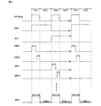
図4は、図2のマルチプレクサーMPXによる選択サンプル・モードの間のアナログ入力信号の選択動作と図2の10ビットの逐次比較型A/D変換器10bit A/D_Convによる変換・モードの間のアナログ入力信号のA/D変換動作との繰り返し動作を説明するための図である。繰り返しの選択サンプル・モードの間にマルチプレクサーMPXは、順番に8チャンネルのアナログ入力端子AN0…AN7のアナログ入力信号電圧を時分割で定期的にまたサンプリングするものである。繰り返しの変換・モードの間に10ビットの逐次比較型A/D変換器10bit A/D_Convは、その直前にマルチプレクサーMPXによってサンプリングされたアナログ入力信号電圧をディジタル信号に変換する。このようにして、10ビットの逐次比較型A/D変換器10bit A/D_Convは、順番に8チャンネルのアナログ入力端子AN0…AN7のアナログ入力信号電圧をディジタル信号にA/D変換するものである。
FIG. 4 shows a selection between the selection operation of the analog input signal by the multiplexer MPX of FIG. 2 and the conversion mode by the 10-bit successive approximation A /
しかし、本発明者等は本発明に先立って検討された図2に示したマルチプレクサーMPXによる8チャンネルのアナログ入力端子AN0…AN7の選択サンプル・モードでは、アナログ入力端子AN0…AN7にサンプリング誤差が生成されると言う問題が明らかとされた。このアナログ入力端子にサンプリング誤差が生成されるメカニズムを本発明者等が検討した結果、下記のような誤差生成メカニズムが明らかとされた。 However, in the selection sample mode of the 8-channel analog input terminals AN0... AN7 by the multiplexer MPX shown in FIG. 2 examined prior to the present invention, the inventors have a sampling error in the analog input terminals AN0. The problem of being generated was clarified. As a result of the study of the mechanism by which the sampling error is generated at the analog input terminal, the following error generation mechanism has been clarified.
それは、次のようなものである。まず、8チャンネルのアナログ入力端子AN0…AN7のアナログ入力信号電圧が、それぞれ一定の直流電圧に安定に維持されているとする。しかし、上述したように、各チャンネルのアナログ入力端子のサンプリング期間の前半でのアナログ出力端子ADCOMの電圧レベルは、ボルテージフォロワの演算増幅器OpAmp0の入力オフセット電圧の影響を含んでいる。また、各チャンネルのアナログ入力端子のサンプリング期間の後半でのアナログ出力端子ADCOMの電圧レベルは、第2スイッチSW02によるバイパス機能によって、ボルテージフォロワの演算増幅器OpAmp0の入力オフセット電圧の影響が低減されたものである。各アナログ入力端子の各アナログ入力信号電圧が一定の直流電圧に安定に維持された状態でアナログ入力端子のサンプリング期間の前半の動作と後半の動作とが繰り返されることによって、各アナログ入力端子はQ=C・Voffの電荷を消費する。ここで、Cは、マルチプレクサーMPXのアナログ出力端子ADCOMの出力寄生容量Cpの容量値である。また、Voffは、マルチプレクサーMPXのアナログ入力端子AN0…AN7の演算増幅器OpAmp0…OpAmp7の入力オフセット電圧の値である。マルチプレクサーMPXの8チャンネルのアナログ入力端子AN0…AN7のサンプリング繰り返し周波数をfとすると、各アナログ入力端子にはi=ΔQ/ΔT=f・C・Voffの電流が流れる。 It is as follows. First, it is assumed that the analog input signal voltages of the 8-channel analog input terminals AN0... AN7 are stably maintained at a constant DC voltage. However, as described above, the voltage level of the analog output terminal ADCOM in the first half of the sampling period of the analog input terminal of each channel includes the influence of the input offset voltage of the operational amplifier OpAmp0 of the voltage follower. The voltage level of the analog output terminal ADCOM in the second half of the sampling period of the analog input terminal of each channel is reduced by the influence of the input offset voltage of the operational amplifier OpAmp0 of the voltage follower by the bypass function by the second switch SW02. It is. By repeating the first half operation and the second half operation of the sampling period of the analog input terminal in a state where each analog input signal voltage of each analog input terminal is stably maintained at a constant DC voltage, each analog input terminal becomes Q = Consumption of C · Voff is consumed. Here, C is a capacitance value of the output parasitic capacitance Cp of the analog output terminal ADCOM of the multiplexer MPX. Voff is the value of the input offset voltage of the operational amplifiers OpAmp0... OpAmp7 of the analog input terminals AN0. If the sampling repetition frequency of the 8-channel analog input terminals AN0... AN7 of the multiplexer MPX is f, a current of i = ΔQ / ΔT = f · C · Voff flows through each analog input terminal.
その結果、マルチプレクサーMPXの各アナログ入力端子AN0…AN7の各抵抗Rin0…Rin7には、Vso=R・f・C・Voffのサンプリング誤差電圧が生成される。ここで、Rはアナログ入力端子AN0…AN7の抵抗Rin0…Rin7の抵抗値である。例えば、抵抗Rが20KΩ、サンプリング繰り返し周波数fが1MHz、出力寄生容量Cが23pF、入力オフセット電圧Voffが10mVとすると、サンプリング誤差電圧Vsoは略4.6mVとなる。 As a result, sampling error voltages of Vso = R · f · C · Voff are generated at the resistors Rin0... Rin7 of the analog input terminals AN0. Here, R is the resistance value of the resistors Rin0... Rin7 of the analog input terminals AN0. For example, if the resistance R is 20 KΩ, the sampling repetition frequency f is 1 MHz, the output parasitic capacitance C is 23 pF, and the input offset voltage Voff is 10 mV, the sampling error voltage Vso is approximately 4.6 mV.
マルチプレクサーMPXの8チャンネルのアナログ入力端子AN0…AN7の抵抗Rin0…Rin7の両端に生成される略4.6mVのサンプリング誤差電圧Vsoは、マルチプレクサーMPXの各アナログ入力端子AN0…AN7の各アナログ入力信号電圧への定常オフセット誤差電圧となる。 The sampling error voltage Vso of approximately 4.6 mV generated across the resistors Rin0... Rin7 of the 8-channel analog input terminals AN0... AN7 of the multiplexer MPX is supplied to the analog inputs of the analog input terminals AN0. It becomes a steady offset error voltage to the signal voltage.
本発明は、以上のような本発明に先立った本発明者等の検討の結果に基づいて、なされたものである。 The present invention has been made based on the results of the study by the present inventors prior to the present invention as described above.
従って、本発明の目的とするところは、A/D変換器の入力端子に接続されたサンプリング回路またはマルチプレクサーを構成する演算増幅器の入力オフセット電圧による入力端子に供給されるアナログ入力信号電圧の信号源インピーダンスでのオフセット誤差電圧を低減することにある。 Accordingly, an object of the present invention is to provide a signal of the analog input signal voltage supplied to the input terminal by the input offset voltage of the operational amplifier constituting the sampling circuit or multiplexer connected to the input terminal of the A / D converter. The object is to reduce the offset error voltage at the source impedance.
本発明の前記ならびにその他の目的と新規な特徴は、本明細書の記述および添付図面から明らかになるであろう。 The above and other objects and novel features of the present invention will be apparent from the description of this specification and the accompanying drawings.
本願において開示される発明のうちの代表的なものについて簡単に説明すれば下記のとおりである。 A typical one of the inventions disclosed in the present application will be briefly described as follows.
すなわち、本発明の代表的な半導体集積回路は、A/D変換器(10bit_A/D_Conv)と、前記A/D変換器の入力端子に接続されたサンプリング回路(MPX)とを具備する(図1、図5参照)。 That is, a typical semiconductor integrated circuit of the present invention includes an A / D converter (10 bit_A / D_Conv) and a sampling circuit (MPX) connected to an input terminal of the A / D converter (FIG. 1). FIG. 5).
前記サンプリング回路は、第1サンプル・モード(Smp_Md1)と第2サンプル・モード(Smp_Md2)とで、前記アナログ入力端子に供給されるアナログ入力信号をサンプリングするものである(図7、図8参照)。 The sampling circuit samples an analog input signal supplied to the analog input terminal in a first sample mode (Smp_Md1) and a second sample mode (Smp_Md2) (see FIGS. 7 and 8). .
前記A/D変換器は、前記サンプリング回路によってサンプリングされたアナログ信号を変換・モードにてディジタル信号に変換する。 The A / D converter converts the analog signal sampled by the sampling circuit into a digital signal in a conversion mode.
前記第1と第2のサンプル・モードとで、演算増幅器OpAmp0の内部回路の切換により、第1と第2の入力端子(In1、In2)とによる非反転入力端子(+)と反転入力端子(−)との機能が交代する。この機能交代と同期して、入力スイッチ(SW01、SW02)によるアナログ信号の非反転入力端子(+)への供給も交代する。 By switching the internal circuit of the operational amplifier OpAmp0 in the first and second sample modes, the non-inverting input terminal (+) and the inverting input terminal (by the first and second input terminals (In1, In2)) The function with-) changes. In synchronization with this function change, the supply of analog signals to the non-inverting input terminal (+) by the input switches (SW01, SW02) is also changed.
その結果、演算増幅器の第1入力端子と前記第2入力端子との間の入力オフセット電圧によるサンプリング回路のアナログ入力端子の信号源インピーダンスでのサンプリング誤差電圧の極性が第1サンプル・モードと第2サンプル・モードとで交代する。従って、極性が交代するサンプリング誤差電圧の時間積分による平均誤差電圧レベルは略ゼロとなるので、信号源インピーダンスでのオフセット誤差電圧を低減することができる。 As a result, the polarity of the sampling error voltage at the signal source impedance of the analog input terminal of the sampling circuit due to the input offset voltage between the first input terminal of the operational amplifier and the second input terminal is the first sample mode and the second input voltage. Alternates with sample mode. Accordingly, the average error voltage level obtained by time integration of the sampling error voltage whose polarity is changed becomes substantially zero, so that the offset error voltage at the signal source impedance can be reduced.
本願において開示される発明のうち代表的なものによって得られる効果を簡単に説明すれば下記の通りである。 The effects obtained by the representative ones of the inventions disclosed in the present application will be briefly described as follows.
すなわち、A/D変換器の入力端子に接続されたサンプリング回路またはマルチプレクサーを構成する演算増幅器の入力オフセット電圧による入力端子に供給されるアナログ入力信号電圧の信号源インピーダンスでのオフセット誤差電圧を低減することができる。 That is, the offset error voltage at the signal source impedance of the analog input signal voltage supplied to the input terminal by the input offset voltage of the operational amplifier constituting the sampling circuit or multiplexer connected to the input terminal of the A / D converter is reduced. can do.
《代表的な実施の形態》
先ず、本願において開示される発明の代表的な実施の形態について概要を説明する。代表的な実施の形態についての概要説明で括弧を付して参照する図面の参照符号はそれが付された構成要素の概念に含まれるものを例示するに過ぎない。
<Typical embodiment>
First, an outline of a typical embodiment of the invention disclosed in the present application will be described. The reference numerals of the drawings referred to with parentheses in the outline description of the representative embodiments merely exemplify what are included in the concept of the components to which the reference numerals are attached.
〔1〕本発明の代表的な実施の形態による半導体集積回路は、A/D変換器(10bit_A/D_Conv)と、前記A/D変換器の入力端子に接続されたサンプリング回路(MPX)とを具備する(図1、図5参照)。 [1] A semiconductor integrated circuit according to a typical embodiment of the present invention includes an A / D converter (10 bit_A / D_Conv) and a sampling circuit (MPX) connected to an input terminal of the A / D converter. Provided (see FIGS. 1 and 5).
前記サンプリング回路は、アナログ入力端子(AN0)、演算増幅器(OpAmp0)、第1スイッチ(SW01)、第2スイッチ(SW02)、第3スイッチ(SW03)、第4スイッチ(SW04)、第5スイッチ(SW05)、アナログ出力端子(ADCOM)を含む。 The sampling circuit includes an analog input terminal (AN0), an operational amplifier (OpAmp0), a first switch (SW01), a second switch (SW02), a third switch (SW03), a fourth switch (SW04), and a fifth switch ( SW05) and an analog output terminal (ADCOM).
前記アナログ入力端子は前記第1スイッチの一端と前記第2スイッチの一端とに接続され、前記第1スイッチの他端と前記第2スイッチの他端とは前記演算増幅器の第1入力端子(In1)と第2入力端子(In2)とにそれぞれ接続されている。 The analog input terminal is connected to one end of the first switch and one end of the second switch, and the other end of the first switch and the other end of the second switch are connected to a first input terminal (In1) of the operational amplifier. ) And the second input terminal (In2).
前記第3スイッチの一端と他端とは前記演算増幅器の前記第1入力端子と前記演算増幅器の出力端子とにそれぞれ接続され、前記第4スイッチの一端と他端とは前記演算増幅器の前記第1入力端子と前記演算増幅器の前記出力端子とにそれぞれ接続されている。 One end and the other end of the third switch are connected to the first input terminal of the operational amplifier and an output terminal of the operational amplifier, respectively, and one end and the other end of the fourth switch are connected to the first input terminal of the operational amplifier. One input terminal is connected to the output terminal of the operational amplifier.
前記演算増幅器の出力端子は、前記アナログ出力端子を介して、前記A/D変換器の入力端子に接続されている。 An output terminal of the operational amplifier is connected to an input terminal of the A / D converter via the analog output terminal.
前記第5スイッチの一端と他端とは、前記演算増幅器をバイパスするように、前記アナログ入力端子と前記アナログ出力端子とにそれぞれ接続されている(図5参照)。 One end and the other end of the fifth switch are respectively connected to the analog input terminal and the analog output terminal so as to bypass the operational amplifier (see FIG. 5).
前記サンプリング回路は、第1サンプル・モード(Smp_Md1)と第2サンプル・モード(Smp_Md2)とで、前記アナログ入力端子に供給されるアナログ入力信号をサンプリングするものである(図7、図8参照)。 The sampling circuit samples an analog input signal supplied to the analog input terminal in a first sample mode (Smp_Md1) and a second sample mode (Smp_Md2) (see FIGS. 7 and 8). .
前記A/D変換器は、前記第1サンプル・モードの後または前記第2サンプル・モードの後の変換・モードにて前記第1サンプル・モードでまたは前記第2サンプル・モードで前記サンプリング回路によってサンプリングされたアナログ信号をディジタル信号に変換するものである(図5参照)。 The A / D converter is in the first sample mode or in the second sample mode in the conversion mode after the first sample mode or after the second sample mode. The sampled analog signal is converted into a digital signal (see FIG. 5).
前記サンプリング回路の前記第1サンプル・モードの前半では、前記第1スイッチと前記第4スイッチとはオン状態に制御される一方、前記第2スイッチと前記第3スイッチと前記第5スイッチとはオフ状態に制御される。 In the first half of the first sample mode of the sampling circuit, the first switch and the fourth switch are controlled to be on, while the second switch, the third switch, and the fifth switch are off. Controlled by the state.
前記サンプリング回路の前記第1サンプル・モードの前記前半では、前記演算増幅器の前記第1入力端子と前記第2入力端子とは前記演算増幅器の非反転入力端子(+)と反転入力端子(−)としてそれぞれ機能するように、前記演算増幅器の内部回路が制御される(図7、図8参照)。 In the first half of the first sample mode of the sampling circuit, the first input terminal and the second input terminal of the operational amplifier are a non-inverting input terminal (+) and an inverting input terminal (−) of the operational amplifier. The internal circuit of the operational amplifier is controlled so as to function respectively (see FIGS. 7 and 8).
前記サンプリング回路の前記第1サンプル・モードの後半では、前記演算増幅器による前記アナログ出力端子の駆動が停止される一方、前記第5スイッチはオン状態に制御される(図8(c)参照)。 In the second half of the first sample mode of the sampling circuit, driving of the analog output terminal by the operational amplifier is stopped, while the fifth switch is controlled to be in an ON state (see FIG. 8C).
前記サンプリング回路の前記第1サンプル・モードの前記後半では、前記アナログ入力端子に供給される前記アナログ入力信号は前記第5スイッチと前記アナログ出力端子とを介して前記A/D変換器の前記入力端子に伝達される(図8(c)参照)。 In the second half of the first sample mode of the sampling circuit, the analog input signal supplied to the analog input terminal is input to the A / D converter via the fifth switch and the analog output terminal. The signal is transmitted to the terminal (see FIG. 8C).
前記サンプリング回路の前記第2サンプル・モードの前半では、前記第1スイッチと前記第4スイッチと前記第5スイッチとはオフ状態に制御される一方、前記第2スイッチと前記第3スイッチとはオン状態に制御される。 In the first half of the second sample mode of the sampling circuit, the first switch, the fourth switch, and the fifth switch are controlled to be turned off, while the second switch and the third switch are turned on. Controlled by the state.
前記サンプリング回路の前記第2サンプル・モードの前記前半では、前記演算増幅器の前記第1入力端子と前記第2入力端子とは前記演算増幅器の反転入力端子(−)と非反転入力端子(+)としてそれぞれ機能するように、前記演算増幅器の前記内部回路が制御される(図7、図8参照)。 In the first half of the second sample mode of the sampling circuit, the first input terminal and the second input terminal of the operational amplifier are an inverting input terminal (−) and a non-inverting input terminal (+) of the operational amplifier. The internal circuits of the operational amplifier are controlled so as to function respectively (see FIGS. 7 and 8).
前記サンプリング回路の前記第2サンプル・モードの後半では、前記演算増幅器による前記アナログ出力端子の駆動が停止される一方、前記第5スイッチはオン状態に制御される(図8(c)参照)。 In the second half of the second sample mode of the sampling circuit, driving of the analog output terminal by the operational amplifier is stopped, while the fifth switch is controlled to be in an ON state (see FIG. 8C).
前記サンプリング回路の前記第2サンプル・モードの前記後半では、前記アナログ入力端子に供給される前記アナログ入力信号は前記第5スイッチと前記アナログ出力端子とを介して前記A/D変換器の前記入力端子に伝達される(図8(c)参照)。 In the second half of the second sample mode of the sampling circuit, the analog input signal supplied to the analog input terminal is input to the A / D converter via the fifth switch and the analog output terminal. The signal is transmitted to the terminal (see FIG. 8C).
前記実施の形態によれば、サンプリング回路の第1サンプル・モードと第2サンプル・モードとで、演算増幅器の第1入力端子と前記第2入力端子とによる非反転入力端子と反転入力端子との機能が交代する。従って、演算増幅器の第1入力端子と前記第2入力端子との間の入力オフセット電圧によるサンプリング回路のアナログ入力端子の信号源インピーダンスでのサンプリング誤差電圧の極性が第1サンプル・モードと第2サンプル・モードとで交代する。その結果、極性が交代するサンプリング誤差電圧の時間積分による平均誤差電圧レベルは略ゼロとなるので、信号源インピーダンスでのオフセット誤差電圧を低減することができる。 According to the embodiment, in the first sample mode and the second sample mode of the sampling circuit, the non-inverting input terminal and the inverting input terminal by the first input terminal and the second input terminal of the operational amplifier The function changes. Accordingly, the polarity of the sampling error voltage at the signal source impedance of the analog input terminal of the sampling circuit due to the input offset voltage between the first input terminal and the second input terminal of the operational amplifier is the first sample mode and the second sample.・ Change with mode. As a result, the average error voltage level by time integration of the sampling error voltage whose polarity is changed becomes substantially zero, so that the offset error voltage at the signal source impedance can be reduced.
好適な実施の形態による半導体集積回路では、前記第1サンプル・モードと前記第2サンプル・モードとは、複数回数、反復される(図8(c)参照)。 In the semiconductor integrated circuit according to a preferred embodiment, the first sample mode and the second sample mode are repeated a plurality of times (see FIG. 8C).
より好適な実施の形態では、前記演算増幅器では差動入力ステージの差動トランジスタ(Qn1、Qn2)と駆動増幅ステージのカスコード接続のカレントミラー負荷トランジスタ(Qn3、Qn5、Qn4、Qn6)とが第1導電型(Nチャンネル)のトランジスタである。前記駆動増幅ステージは、前記第1導電型と反対の第2導電型(Pチャンネル)のゲート接地トランジスタ対(Qp3、Qp4)を含んでいる。前記差動トランジスタの差動出力信号が前記駆動増幅ステージの前記ゲート接地トランジスタ対を介して前記カレントミラー負荷トランジスタに供給されることにより、前記演算増幅器はフォールデッド・カスコード型の演算増幅器として構成されている(図7参照)。 In a more preferred embodiment, in the operational amplifier, the differential transistors (Qn1, Qn2) in the differential input stage and the cascode-connected current mirror load transistors (Qn3, Qn5, Qn4, Qn6) in the drive amplification stage are the first. It is a conductive type (N-channel) transistor. The drive amplification stage includes a second conductive type (P channel) common-gate transistor pair (Qp3, Qp4) opposite to the first conductive type. The operational amplifier is configured as a folded cascode operational amplifier by supplying the differential output signal of the differential transistor to the current mirror load transistor through the common gate transistor pair of the drive amplification stage. (See FIG. 7).
他のより好適な実施の形態では、前記演算増幅器は第1導電型(Nチャンネル)の第1差動トランジスタ(Qn1、Qn2)と前記第1導電型と反対の第2導電型(Pチャンネル)の第2差動トランジスタ(Qp11、Qp12)とを含むレイル・ツー・レイル型の差動入力ステージを含んでいる(図10参照)。 In another more preferred embodiment, the operational amplifier includes a first conductivity type (N channel) first differential transistor (Qn1, Qn2) and a second conductivity type (P channel) opposite to the first conductivity type. A rail-to-rail differential input stage including a second differential transistor (Qp11, Qp12) (see FIG. 10).
具体的な一つの実施の形態では、前記差動入力ステージは差動入力コモン・モード電圧(VCP、VCN)の変動による前記差動入力ステージの相互コンダクタンスの変動を低減するコンダクタンス制御回路(Gm_Cnt)を含んでいる(図10参照)。 In a specific embodiment, the differential input stage has a conductance control circuit that reduces a variation in mutual conductance of the differential input stage due to a variation in differential input common mode voltage (V CP , V CN ). Gm_Cnt) (see FIG. 10).
他の具体的な一つの実施の形態では、前記A/D変換器は、逐次比較型A/D変換器、フラッシュ型A/D変換器、ΣΔ型A/D変換器、パイプライン型A/D変換器のいずれかである(図5、図18、図19参照)。 In another specific embodiment, the A / D converter includes a successive approximation A / D converter, a flash A / D converter, a ΣΔ A / D converter, and a pipeline A / D converter. One of the D converters (see FIGS. 5, 18, and 19).
別な具体的な一つの実施の形態では、前記A/D変換器により変換された前記ディジタル信号は中央処理ユニット(CPU)に供給されるものである(図5参照)。 In another specific embodiment, the digital signal converted by the A / D converter is supplied to a central processing unit (CPU) (see FIG. 5).
最も具体的な一つの実施の形態では、前記演算増幅器はCMOSアナログ演算増幅器により構成され、前記第1スイッチ、前記第2スイッチ、前記第3スイッチ、前記第4スイッチ、前記第5スイッチのそれぞれはCMOSアナログにより構成されているものである(図5参照)。 In a most specific embodiment, the operational amplifier comprises a CMOS analog operational amplifier, and each of the first switch, the second switch, the third switch, the fourth switch, and the fifth switch is It is composed of CMOS analog (see FIG. 5).
〔2〕本発明の別の観点の代表的な実施の形態による半導体集積回路は、A/D変換器(10bit_A/D_Conv)と、前記A/D変換器の入力端子に接続されたマルチプレクサー(MPX)とを具備する(図1、図5参照)。 [2] A semiconductor integrated circuit according to a representative embodiment of another aspect of the present invention includes an A / D converter (10 bit_A / D_Conv) and a multiplexer connected to an input terminal of the A / D converter ( MPX) (see FIGS. 1 and 5).
前記マルチプレクサーは、複数のアナログ入力端子(AN0)、アナログ出力端子(ADCOM)、前記複数のアナログ入力端子と前記アナログ出力端子との間の複数のチャンネルを含む。 The multiplexer includes a plurality of analog input terminals (AN0), an analog output terminal (ADCOM), and a plurality of channels between the plurality of analog input terminals and the analog output terminal.
前記マルチプレクサーの前記複数のチャンネルのそれぞれは、演算増幅器(OpAmp0)、第1スイッチ(SW01)、第2スイッチ(SW02)、第3スイッチ(SW03)、第4スイッチ(SW04)、第5スイッチ(SW05)、アナログ出力端子(ADCOM)を含む。 Each of the plurality of channels of the multiplexer includes an operational amplifier (OpAmp0), a first switch (SW01), a second switch (SW02), a third switch (SW03), a fourth switch (SW04), and a fifth switch ( SW05) and an analog output terminal (ADCOM).
前記マルチプレクサーの前記複数のチャンネルのそれぞれで、各アナログ入力端子は各第1スイッチの一端と各第2スイッチの一端とに接続され、前記第1スイッチの他端と前記第2スイッチの他端とは各演算増幅器の第1入力端子(In1)と第2入力端子(In2)とにそれぞれ接続されている。 In each of the plurality of channels of the multiplexer, each analog input terminal is connected to one end of each first switch and one end of each second switch, and the other end of the first switch and the other end of the second switch. Are connected to the first input terminal (In1) and the second input terminal (In2) of each operational amplifier.
前記マルチプレクサーの前記複数のチャンネルのそれぞれで、各第3スイッチの一端と他端とは各演算増幅器の前記第1入力端子と前記演算増幅器の出力端子とにそれぞれ接続され、各第4スイッチの一端と他端とは前記演算増幅器の前記第1入力端子と前記演算増幅器の前記出力端子とにそれぞれ接続されている。 In each of the plurality of channels of the multiplexer, one end and the other end of each third switch are connected to the first input terminal of each operational amplifier and the output terminal of the operational amplifier, respectively. One end and the other end are respectively connected to the first input terminal of the operational amplifier and the output terminal of the operational amplifier.
前記マルチプレクサーの前記複数のチャンネルのそれぞれで、各演算増幅器の出力端子は、前記アナログ出力端子を介して、前記A/D変換器の入力端子に接続されている。 In each of the plurality of channels of the multiplexer, the output terminal of each operational amplifier is connected to the input terminal of the A / D converter via the analog output terminal.
前記マルチプレクサーの前記複数のチャンネルのそれぞれで、各第5スイッチの一端と他端とは、各演算増幅器をバイパスするように、各アナログ入力端子と前記アナログ出力端子とにそれぞれ接続されている(図5参照)。 In each of the plurality of channels of the multiplexer, one end and the other end of each fifth switch are connected to each analog input terminal and each analog output terminal so as to bypass each operational amplifier. (See FIG. 5).
前記マルチプレクサーは、第1サンプル・モード(Smp_Md1)と第2サンプル・モード(Smp_Md2)とで、複数のアナログ入力端子から選択される任意のアナログ入力端子に供給されるアナログ入力信号をサンプリングするものである(図7、図8参照)。 The multiplexer samples an analog input signal supplied to an arbitrary analog input terminal selected from a plurality of analog input terminals in the first sample mode (Smp_Md1) and the second sample mode (Smp_Md2). (See FIGS. 7 and 8).
前記A/D変換器は、前記第1サンプル・モードの後または前記第2サンプル・モードの後の変換・モードにて前記第1サンプル・モードでまたは前記第2サンプル・モードで前記マルチプレクサーによってサンプリングされたアナログ信号をディジタル信号に変換するものである(図5参照)。 The A / D converter is in the first sample mode in the conversion mode after the first sample mode or after the second sample mode or by the multiplexer in the second sample mode. The sampled analog signal is converted into a digital signal (see FIG. 5).
前記マルチプレクサーの前記第1サンプル・モードの前半では、前記第1スイッチと前記第4スイッチとはオン状態に制御される一方、前記第2スイッチと前記第3スイッチと前記第5スイッチとはオフ状態に制御される。 In the first half of the first sample mode of the multiplexer, the first switch and the fourth switch are controlled to be on, while the second switch, the third switch, and the fifth switch are off. Controlled by the state.
前記マルチプレクサーの前記第1サンプル・モードの前記前半では、前記演算増幅器の前記第1入力端子と前記第2入力端子とは前記演算増幅器の非反転入力端子(+)と反転入力端子(−)としてそれぞれ機能するように、前記演算増幅器の内部回路が制御される(図7、図8参照)。 In the first half of the first sample mode of the multiplexer, the first input terminal and the second input terminal of the operational amplifier are a non-inverting input terminal (+) and an inverting input terminal (-) of the operational amplifier. The internal circuit of the operational amplifier is controlled so as to function respectively (see FIGS. 7 and 8).
前記マルチプレクサーの前記第1サンプル・モードの後半では、前記演算増幅器による前記アナログ出力端子の駆動が停止される一方、前記第5スイッチはオン状態に制御される(図8(c)参照)。 In the second half of the first sample mode of the multiplexer, the operation of the analog output terminal by the operational amplifier is stopped, while the fifth switch is controlled to be in an ON state (see FIG. 8C).
前記マルチプレクサーの前記第1サンプル・モードの前記後半では、前記アナログ入力端子に供給される前記アナログ入力信号は前記第5スイッチと前記アナログ出力端子とを介して前記A/D変換器の前記入力端子に伝達される(図8(c)参照)。 In the second half of the first sample mode of the multiplexer, the analog input signal supplied to the analog input terminal is input to the A / D converter via the fifth switch and the analog output terminal. The signal is transmitted to the terminal (see FIG. 8C).
前記マルチプレクサーの前記第2サンプル・モードの前半では、前記第1スイッチと前記第4スイッチと前記第5スイッチとはオフ状態に制御される一方、前記第2スイッチと前記第3スイッチとはオン状態に制御される。 In the first half of the second sample mode of the multiplexer, the first switch, the fourth switch, and the fifth switch are controlled to be turned off, while the second switch and the third switch are turned on. Controlled by the state.
前記マルチプレクサーの前記第2サンプル・モードの前記前半では、前記演算増幅器の前記第1入力端子と前記第2入力端子とは前記演算増幅器の反転入力端子(−)と非反転入力端子(+)としてそれぞれ機能するように、前記演算増幅器の前記内部回路が制御される(図7、図8参照)。 In the first half of the second sample mode of the multiplexer, the first input terminal and the second input terminal of the operational amplifier are an inverting input terminal (−) and a non-inverting input terminal (+) of the operational amplifier. The internal circuits of the operational amplifier are controlled so as to function respectively (see FIGS. 7 and 8).
前記マルチプレクサーの前記第2サンプル・モードの後半では、前記演算増幅器による前記アナログ出力端子の駆動が停止される一方、前記第5スイッチはオン状態に制御される(図8(c)参照)。 In the second half of the second sample mode of the multiplexer, the operation of the analog output terminal by the operational amplifier is stopped, while the fifth switch is controlled to be in an ON state (see FIG. 8C).
前記マルチプレクサーの前記第2サンプル・モードの前記後半では、前記アナログ入力端子に供給される前記アナログ入力信号は前記第5スイッチと前記アナログ出力端子とを介して前記A/D変換器の前記入力端子に伝達される(図8(c)参照)。 In the second half of the second sample mode of the multiplexer, the analog input signal supplied to the analog input terminal is input to the A / D converter via the fifth switch and the analog output terminal. The signal is transmitted to the terminal (see FIG. 8C).
前記実施の形態によれば、マルチプレクサーの第1サンプル・モードと第2サンプル・モードとで、演算増幅器の第1入力端子と前記第2入力端子とによる非反転入力端子と反転入力端子との機能が交代する。従って、演算増幅器の第1入力端子と前記第2入力端子との間の入力オフセット電圧によるマルチプレクサーのアナログ入力端子の信号源インピーダンスでのサンプリング誤差電圧の極性が第1サンプル・モードと第2サンプル・モードとで交代する。その結果、極性が交代するサンプリング誤差電圧の時間積分による平均誤差電圧レベルは略ゼロとなるので、信号源インピーダンスでのオフセット誤差電圧を低減することができる。 According to the embodiment, in the first sample mode and the second sample mode of the multiplexer, the non-inverting input terminal and the inverting input terminal by the first input terminal and the second input terminal of the operational amplifier The function changes. Therefore, the polarity of the sampling error voltage at the signal source impedance of the analog input terminal of the multiplexer due to the input offset voltage between the first input terminal and the second input terminal of the operational amplifier is the first sample mode and the second sample.・ Change with mode. As a result, the average error voltage level by time integration of the sampling error voltage whose polarity is changed becomes substantially zero, so that the offset error voltage at the signal source impedance can be reduced.
好適な実施の形態による半導体集積回路では、前記第1サンプル・モードと前記第2サンプル・モードとは、複数回数、反復される(図8(c)参照)。 In the semiconductor integrated circuit according to a preferred embodiment, the first sample mode and the second sample mode are repeated a plurality of times (see FIG. 8C).
より好適な実施の形態では、前記演算増幅器では差動入力ステージの差動トランジスタ(Qn1、Qn2)と駆動増幅ステージのカスコード接続のカレントミラー負荷トランジスタ(Qn3、Qn5、Qn4、Qn6)とが第1導電型(Nチャンネル)のトランジスタである。前記駆動増幅ステージは、前記第1導電型と反対の第2導電型(Pチャンネル)のゲート接地トランジスタ対(Qp3、Qp4)を含んでいる。前記差動トランジスタの差動出力信号が前記駆動増幅ステージの前記ゲート接地トランジスタ対を介して前記カレントミラー負荷トランジスタに供給されることにより、前記演算増幅器はフォールデッド・カスコード型の演算増幅器として構成されている(図7参照)。 In a more preferred embodiment, in the operational amplifier, the differential transistors (Qn1, Qn2) in the differential input stage and the cascode-connected current mirror load transistors (Qn3, Qn5, Qn4, Qn6) in the drive amplification stage are the first. It is a conductive type (N-channel) transistor. The drive amplification stage includes a second conductive type (P channel) common-gate transistor pair (Qp3, Qp4) opposite to the first conductive type. The operational amplifier is configured as a folded cascode operational amplifier by supplying the differential output signal of the differential transistor to the current mirror load transistor through the common gate transistor pair of the drive amplification stage. (See FIG. 7).
他のより好適な実施の形態では、前記演算増幅器は第1導電型(Nチャンネル)の第1差動トランジスタ(Qn1、Qn2)と前記第1導電型と反対の第2導電型(Pチャンネル)の第2差動トランジスタ(Qp11、Qp12)とを含むレイル・ツー・レイル型の差動入力ステージを含んでいる(図10参照)。 In another more preferred embodiment, the operational amplifier includes a first conductivity type (N channel) first differential transistor (Qn1, Qn2) and a second conductivity type (P channel) opposite to the first conductivity type. A rail-to-rail differential input stage including a second differential transistor (Qp11, Qp12) (see FIG. 10).
具体的な一つの実施の形態では、前記差動入力ステージは差動入力コモン・モード電圧(VCP、VCN)の変動による前記差動入力ステージの相互コンダクタンスの変動を低減するコンダクタンス制御回路(Gm_Cnt)を含んでいる(図10参照)。 In a specific embodiment, the differential input stage has a conductance control circuit that reduces a variation in mutual conductance of the differential input stage due to a variation in differential input common mode voltage (V CP , V CN ). Gm_Cnt) (see FIG. 10).
別の1つ目の具体的な一つの実施の形態では、前記マルチプレクサーの前記複数のチャンネルの近接した2つのチャンネルは1個の演算増幅器を共有するものである(図14、図16参照)。 In another specific one embodiment, two adjacent channels of the plurality of channels of the multiplexer share one operational amplifier (see FIGS. 14 and 16). .
別の2つ目の具体的な一つの実施の形態では、前記マルチプレクサーの前記複数のチャンネルの近接した2つのチャンネルはそれぞれ専用の演算増幅器の差動増幅ステージを含み、前記近接した2つのチャンネルは前記差動増幅ステージからの信号が供給される演算増幅器の1個の駆動増幅ステージ・出力増幅ステージを共有するものである(図16参照)。 In another second specific embodiment, the two adjacent channels of the plurality of channels of the multiplexer each include a differential amplifier stage of a dedicated operational amplifier, the two adjacent channels Is one that shares one drive amplification stage and output amplification stage of an operational amplifier to which a signal from the differential amplification stage is supplied (see FIG. 16).
他の具体的な一つの実施の形態では、前記A/D変換器は、逐次比較型A/D変換器、フラッシュ型A/D変換器、ΣΔ型A/D変換器、パイプライン型A/D変換器のいずれかである(図5、図18、図19参照)。 In another specific embodiment, the A / D converter includes a successive approximation A / D converter, a flash A / D converter, a ΣΔ A / D converter, and a pipeline A / D converter. One of the D converters (see FIGS. 5, 18, and 19).
最も具体的な一つの実施の形態では、前記演算増幅器はCMOSアナログ演算増幅器により構成され、前記第1スイッチ、前記第2スイッチ、前記第3スイッチ、前記第4スイッチ、前記第5スイッチのそれぞれはCMOSアナログにより構成されているものである(図5参照)。 In a most specific embodiment, the operational amplifier comprises a CMOS analog operational amplifier, and each of the first switch, the second switch, the third switch, the fourth switch, and the fifth switch is It is composed of CMOS analog (see FIG. 5).
《実施の形態の説明》
次に、実施の形態について更に詳述する。
<< Description of Embodiment >>
Next, the embodiment will be described in more detail.
《車載用マイクロコンピュータ》
図1は、本発明の1つの実施の形態によるモノリシック半導体集積回路を示す図である。このモノリシック半導体集積回路は、上記特許文献1に記載されたように半導体集積回路の半導体基板にアナログマルチプレクサーと逐次比較型A/D変換器とを含む車載用マイクロコンピュータである。
《In-vehicle microcomputer》
FIG. 1 is a diagram showing a monolithic semiconductor integrated circuit according to an embodiment of the present invention. This monolithic semiconductor integrated circuit is an in-vehicle microcomputer that includes an analog multiplexer and a successive approximation A / D converter on a semiconductor substrate of a semiconductor integrated circuit as described in
同図に示すように、半導体集積回路の半導体チップは、アナログ回路部Analog_Cirと、ディジタル回路部Digital_Cirと、中央処理ユニット(CPU;図示せず)とを含んでいる。 As shown in the figure, the semiconductor chip of the semiconductor integrated circuit includes an analog circuit unit Analog_Cir, a digital circuit unit Digital_Cir, and a central processing unit (CPU; not shown).
アナログ回路部Analog_Cirは、8チャンネルのアナログ入力端子AN0、AN1、AN2…AN7と1チャンネルのアナログ出力のマルチプレクサーMPXと、10ビットの逐次比較型A/D変換器10bit A/D_Convとを含んでいる。また、アナログ回路部Analog_Cirは、10ビットの局部D/A変換器 10bit Local D/A_Convを含んでいる。 The analog circuit unit Analog_Cir includes 8-channel analog input terminals AN0, AN1, AN2,... AN7, a 1-channel analog output multiplexer MPX, and a 10-bit successive approximation A / D converter 10bit A / D_Conv. Yes. The analog circuit unit Analog_Cir includes a 10-bit local D / A converter 10-bit Local D / A_Conv.
ディジタル回路部Digital_Cirは、コントロール回路Control_Cirを含んでいる。このコントロール回路Control_Cirは、10ビットの逐次比較型A/D変換器10bit A/D_Convにより制御され、局部D/A変換器用レジスタLocal D/A Regを介して10ビットの局部D/A変換器10bit Local D/A_Convを制御する。このコントロール回路Control_Cirには、4個のデータレジスタData Reg A、B、C、D、ステータスレジスタStatue Reg、コントロールレジスタControl Regが接続されている。4個のデータレジスタData Reg A、B、C、D、ステータスレジスタStatue Reg、コントロールレジスタControl Regには、モジュールデータバスMod_Data_Busを介してバスインターフェースBus_Intが接続されている。このバスインターフェースBus_Intには、更に内部データバスInt_Data_Busが接続される。尚、このバスインターフェースBus_Intには、図示されていないが、周辺バスとバススイッチコントローラ(バス制御回路)とを介して中央処理ユニット(CPU)が接続されている。また、必要に応じてディジタル信号処理ユニット(DSP)が周辺バスとバススイッチコントローラとを介してバスインターフェースBus_Intに接続されることもできる。A/D変換器は、周辺バスを介して、中央処理ユニット、ディジタル信号処理ユニット、または図示はされていないが、周辺バスへ接続されるその他の回路へA/D変換結果を出力可能とされている。
The digital circuit unit Digital_Cir includes a control circuit Control_Cir. This control circuit Control_Cir is controlled by a 10-bit successive approximation type A /
アナログ回路部Analog_Cirの10ビットの局部D/A変換器10bit Local D/A_Convは、直列接続された257個の抵抗R0、R1…R127、R128、R129、R130、R131…R255、R256を含んでいる。この10ビットの局部D/A変換器10bit Local D/A_Convは、上位8ビットのデコーダ8bit DECによって制御される256個の上位ビットスイッチと、下位2ビットのデコーダ2bit DECによって制御される4個の下位ビットスイッチとを含んでいる。
The 10-bit local D /
10ビットの局部D/A変換器10bit Local D/A_Convの256個の上位ビットスイッチにより選択された上位ビット基準電圧VREF1が、演算増幅器OP1を介して10ビットの逐次比較型A/D変換器10bit A/D_Convの比較器Compの入力のサンプリング容量C1に供給される。10ビットの局部D/A変換器10bit Local D/A_Convの4個の下位ビットスイッチにより選択された下位ビット基準電圧VREF2が、演算増幅器OP2を介して10ビットの逐次比較型A/D変換器10bit A/D_Convの比較器Compの入力の他のサンプリング容量C4に供給される。尚、上記特許文献1に記載されたように、演算増幅器OP1、OP2のそれぞれの非反転入力端子と出力端子との間にはオフセット電圧の影響を低減するトランスファスイッチSW1、SW2が接続されている。
10-bit local D / A converter 10-bit local D / A_Conv high-order bit reference voltage V REF1 selected by 256 high-order bit switches is converted to a 10-bit successive approximation A / D converter via an operational amplifier OP1. It is supplied to the sampling capacitor C1 at the input of the comparator Comp of 10-bit A / D_Conv. A low-order bit reference voltage V REF2 selected by four low-order bit switches of a 10-bit local D / A converter 10-bit local D / A_Conv is converted into a 10-bit successive approximation A / D converter via an operational amplifier OP2. It is supplied to the other sampling capacitor C4 of the input of the comparator Comp of 10-bit A / D_Conv. As described in
まず、演算増幅器OP1、OP2が活性化され、トランスファスイッチSW1、SW2がオフ状態に制御される。その後、演算増幅器OP1、OP2が非活性化されている間に、トランスファスイッチSW1、SW2がオン状態に制御され、演算増幅器OP1、OP2のオフセット電圧の影響が低減された上位ビット基準電圧VREF1と下位ビット基準電圧VREF2とが生成されることができる。 First, the operational amplifiers OP1 and OP2 are activated, and the transfer switches SW1 and SW2 are controlled to be turned off. Thereafter, while the operational amplifiers OP1 and OP2 are inactivated, the transfer switches SW1 and SW2 are controlled to be in an on state, and the upper bit reference voltage V REF1 in which the influence of the offset voltage of the operational amplifiers OP1 and OP2 is reduced. A lower bit reference voltage V REF2 may be generated.
また10ビットの逐次比較型A/D変換器10bit A/D_ConvのA/D変換動作は、次のように実行される。 The A / D conversion operation of the 10-bit successive approximation type A / D converter 10bit A / D_Conv is executed as follows.
まず、サンプル・モードでは、マルチプレクサーMPXによって8チャンネルのアナログ入力端子AN0、AN1、AN2…AN7のいずれかの入力端子のアナログ入力信号電圧が選択されて、この選択アナログ入力信号電圧は1チャンネルのアナログ出力端子ADCOMに出力される。このアナログ出力端子ADCOMの選択アナログ入力信号電圧は、スイッチSW3を介してサンプリング容量C1の一端に供給される。この時に、比較器Compの演算増幅器の非反転入力端子+は接地電圧GNDに接続され、演算増幅器の反転入力端子−と出力端子との間のスイッチSW4はオン状態に制御されているので、反転入力端子−は仮想接地電位に設定されている。従って、サンプリング容量C1の他端も仮想接地電位であるので、アナログ出力端子ADCOMの選択アナログ入力信号電圧はサンプリング容量C1の両端の間に印加される。 First, in the sample mode, the multiplexer MPX selects the analog input signal voltage of any one of the 8-channel analog input terminals AN0, AN1, AN2,... AN7, and the selected analog input signal voltage is 1 channel. It is output to the analog output terminal ADCOM. The selected analog input signal voltage of the analog output terminal ADCOM is supplied to one end of the sampling capacitor C1 through the switch SW3. At this time, the non-inverting input terminal + of the operational amplifier of the comparator Comp is connected to the ground voltage GND, and the switch SW4 between the inverting input terminal − and the output terminal of the operational amplifier is controlled to be in the ON state. The input terminal − is set to a virtual ground potential. Accordingly, since the other end of the sampling capacitor C1 is also a virtual ground potential, the selected analog input signal voltage of the analog output terminal ADCOM is applied between both ends of the sampling capacitor C1.
次に、変換・モードでは、演算増幅器の反転入力端子−と出力端子との間のスイッチSW4はオフ状態に制御され、演算増幅器OP1の上位ビット基準電圧VREF1はスイッチSW3を介してサンプリング容量C1の一端に供給され、演算増幅器OP2の下位ビット基準電圧VREF2は容量C4の一端に供給される。すると、上位ビットと下位ビットの加算基準電圧と選択アナログ入力信号電圧との差電圧の正負の符号に応じて、比較器Compの演算増幅器の出力端子から論理判定結果が得られる。 Next, in the conversion mode, the switch SW4 between the inverting input terminal − and the output terminal of the operational amplifier is controlled to be in the OFF state, and the upper bit reference voltage V REF1 of the operational amplifier OP1 is sampled via the switch SW3. is supplied to the one end, the lower bit reference voltage V REF2 of the operational amplifier OP2 is supplied to one end of the capacitor C4. Then, a logical determination result is obtained from the output terminal of the operational amplifier of the comparator Comp in accordance with the sign of the difference voltage between the addition reference voltage of the upper and lower bits and the selected analog input signal voltage.
このサンプル・モードと変換・モードの動作の間に、上記非特許文献2に記載されたように、相関二重サンプリングによって10ビットの逐次比較型A/D変換器10bit A/D_Convの比較器Compを構成する演算増幅器のオフセット電圧の影響を低減することができる。
Between the operations of the sample mode and the conversion mode, as described in
コントロール回路Control_Cirは、比較器Compの論理判定結果に応答して例えばバイナリサーチ(2分探査法)等の所定のサーチアルゴリズムに従って局部D/A変換器用レジスタLocal D/A Regのレジスタ保持データの内容を更新する。すなわち、選択アナログ入力信号電圧が10ビットの逐次比較型A/D変換器10bit A/D_Convのアナログ入力ダイナミックレンジの1/2より大きいか小さいかの判定の後、この判定結果から次の判定基準をダイナミックレンジの3/4とするかダイナミックレンジの1/4とするかが決定される。この次の判定基準は、局部D/A変換器用レジスタLocal D/A Regの更新レジスタ保持データの内容に応答する10ビットの局部D/A変換器10bit Local D/A_Convからの上位ビット基準電圧VREF1と下位ビット基準電圧VREF2とによって決定される。
The control circuit Control_Cir responds to the logical determination result of the comparator Comp in accordance with a predetermined search algorithm such as binary search (binary search method), for example, and the contents of the data held in the local D / A converter register Local D / A Reg Update. That is, after determining whether the selected analog input signal voltage is larger or smaller than ½ of the analog input dynamic range of the 10-bit successive approximation A / D converter 10bit A / D_Conv, the next determination criterion is determined from the determination result. Is determined to be 3/4 of the dynamic range or 1/4 of the dynamic range. This next criterion is the upper bit reference voltage V from the 10-bit local D /
例えば、バイナリサーチ等の所定のサーチアルゴリズムによる判定を繰り返すことによって、局部D/A変換器用レジスタLocal D/A Regのレジスタ保持データの内容は、選択アナログ入力信号電圧の10ビットのA/D変換結果に収束することになる。 For example, by repeating the determination based on a predetermined search algorithm such as binary search, the content of the data held in the local D / A converter register Local D / A Reg is converted to 10-bit A / D conversion of the selected analog input signal voltage. It will converge to the result.
《マルチプレクサーの内部構成とマルチプレクサーのアナログ入力端子の外部回路》
図5は、図1に示した本発明の1つの実施の形態によるモノリシック半導体集積回路のマルチプレクサーMPXの内部構成とマルチプレクサーMPXのアナログ入力端子AN0、AN1…AN7に接続される外部回路とを示す図である。尚、この外部回路は、自動車に搭載される車載部品によって構成されている。
<Internal configuration of multiplexer and external circuit of analog input terminal of multiplexer>
FIG. 5 shows an internal configuration of the multiplexer MPX of the monolithic semiconductor integrated circuit according to one embodiment of the present invention shown in FIG. 1 and external circuits connected to the analog input terminals AN0, AN1... AN7 of the multiplexer MPX. FIG. In addition, this external circuit is comprised by the vehicle-mounted components mounted in a motor vehicle.
図5で、8個の種々の車載センサSen0、Sen1…Sen7が、それぞれ抵抗Rin0、Rin1…Rin7と容量Cino、Cin1…Cin7とを介して、マルチプレクサーMPXのアナログ入力端子AN0、AN1…AN7にそれぞれ接続されている。また、車載センサSen0、Sen1…Sen7の一端には自動車のバッテリー電圧が供給され、車載センサSen0、Sen1…Sen7の他端は抵抗Rin0、Rin1…Rin7に接続されている。マルチプレクサーMPXのアナログ入力端子AN0…AN7の抵抗Rin0…Rin7は、車載センサSen0…Sen7の故障により自動車のバッテリー電圧(12ボルト)がマルチプレクサーMPXのアナログ入力端子AN0…AN7に直接供給されることを回避するためのもので、20KΩの抵抗値である。抵抗Rin0…Rin7に接続された容量Cino…Cin7は車載センサSen0…Sen7からのサージ電圧パルスを吸収するためのもので、略0.1マイクロファラドの容量値である。8個の車載センサSen0、Sen1…Sen7は、温度センサ、圧力センサ、加速度センサ等の自動車の運転状態に関する種々のエンジン関連情報やハンドル操作やブレーキ操作に応答するタイヤのスキッド情報等を出力するものである。 In FIG. 5, eight on-vehicle sensors Sen0, Sen1... Sen7 are connected to analog input terminals AN0, AN1... AN7 of the multiplexer MPX through resistors Rin0, Rin1... Rin7 and capacitors Cino, Cin1. Each is connected. Further, the vehicle battery voltage is supplied to one end of the in-vehicle sensors Sen0, Sen1,... Sen7, and the other end of the in-vehicle sensors Sen0, Sen1... Sen7 is connected to the resistors Rin0, Rin1,. The resistors Rin0... Rin7 of the analog input terminals AN0... AN7 of the multiplexer MPX are supplied directly to the analog input terminals AN0... AN7 of the multiplexer MPX due to the failure of the in-vehicle sensor Sen0. This is a resistance value of 20 KΩ. Capacitors Cino ... Cin7 connected to the resistors Rin0 ... Rin7 are for absorbing surge voltage pulses from the in-vehicle sensors Sen0 ... Sen7, and have a capacitance value of about 0.1 microfarad. Eight onboard sensors Sen0, Sen1 ... Sen7 output various engine related information about the driving state of the vehicle such as temperature sensor, pressure sensor, acceleration sensor, tire skid information responding to steering wheel operation and braking operation, etc. It is.
また、図5に示すように、マルチプレクサーMPXの各チャンネルは、演算増幅器OpAmp0…7、第1スイッチSW01…71、第2スイッチSW02…72、第3スイッチSW03…73、第4スイッチSW04…74、第5スイッチSW05…75、第6スイッチSW06…76によって構成されている。まず、演算増幅器OpAmp0…OpAmp7の第1入力端子In1は、第1スイッチSW01…71を介してマルチプレクサーMPXのアナログ入力端子AN0…AN7に接続されている。次に、演算増幅器OpAmp0…OpAmp7の第2入力端子In2は、第2スイッチSW02…72を介してマルチプレクサーMPXのアナログ入力端子AN0…AN7に接続されている。演算増幅器OpAmp0…OpAmp7の出力端子は第3スイッチSW03…73を介して第1入力端子In1に接続され、また演算増幅器OpAmp0…OpAmp7の出力端子は第4スイッチSW04…74を介して第2入力端子In2に接続されている。更に、演算増幅器OpAmp0…OpAmp7の出力端子は、第6スイッチSW06…76を介して10ビットの逐次比較型A/D変換器10bit A/D_ConvのスイッチSW3の一方の入力端子ADCOMに接続される。また、第5スイッチSW05…75は、演算増幅器OpAmp0…7と第6スイッチSW06…76とをバイパスして、マルチプレクサーMPXのアナログ入力端子AN0…AN7を逐次比較型A/D変換器10bit A/D_ConvのスイッチSW3の一方の入力端子ADCOMに接続する。 Further, as shown in FIG. 5, each channel of the multiplexer MPX includes operational amplifiers OpAmp0 ... 7, first switch SW01 ... 71, second switch SW02 ... 72, third switch SW03 ... 73, fourth switch SW04 ... 74. , Fifth switches SW05... 75 and sixth switches SW06. First, the first input terminals In1 of the operational amplifiers OpAmp0... OpAmp7 are connected to the analog input terminals AN0... AN7 of the multiplexer MPX via the first switches SW01. Next, the second input terminals In2 of the operational amplifiers OpAmp0 ... OpAmp7 are connected to the analog input terminals AN0 ... AN7 of the multiplexer MPX via the second switches SW02 ... 72. The output terminals of the operational amplifiers OpAmp0... OpAmp7 are connected to the first input terminal In1 via the third switch SW03... 73, and the output terminals of the operational amplifiers OpAmp0. Connected to In2. Further, the output terminals of the operational amplifiers OpAmp0... OpAmp7 are connected to one input terminal ADCOM of the switch SW3 of the 10-bit successive approximation type A / D converter 10bit A / D_Conv via the sixth switches SW06. The fifth switch SW05 ... 75 bypasses the operational amplifiers OpAmp0 ... 7 and the sixth switch SW06 ... 76, and connects the analog input terminals AN0 ... AN7 of the multiplexer MPX to the successive approximation A / D converter 10bit A / It is connected to one input terminal ADCOM of the switch SW3 of D_Conv.
尚、演算増幅器OpAmp0…7はCMOSアナログ演算増幅器により構成され、第1スイッチSW01…71、第2スイッチSW02…72、第3スイッチSW03…73、第4スイッチSW04…74、第5スイッチSW05…75、第6スイッチSW06…76の各スイッチはCMOSアナログにより構成されているものである。 The operational amplifiers OpAmp0... 7 are composed of CMOS analog operational amplifiers. The first switch SW01... 71, the second switch SW02... 72, the third switch SW03... 73, the fourth switch SW04. Each switch of the sixth switches SW06... 76 is composed of CMOS analog.
《マルチプレクサーでの第1選択サンプル・モードと第2選択サンプル・モードの反復》
マルチプレクサーMPXのアナログ入力端子AN0…AN7の各アナログ入力端子の選択サンプル・モードは、図8に示すように第1選択サンプル・モードSmp_Md1と第2選択サンプル・モードSmp_Md2との反復となる。
<< Repeating the first and second selected sample modes in the multiplexer >>
As shown in FIG. 8, the selected sample mode of the analog input terminals AN0... AN7 of the multiplexer MPX is a repetition of the first selected sample mode Smp_Md1 and the second selected sample mode Smp_Md2.
図8は、図5に示したマルチプレクサーMPXの選択サンプル・モードの第1選択サンプル・モードSmp_Md1と第2選択サンプル・モードSmp_Md2との間のアナログ入力信号の選択動作を説明するための図である。 FIG. 8 is a diagram for explaining an analog input signal selection operation between the first selected sample mode Smp_Md1 and the second selected sample mode Smp_Md2 of the selected sample mode of the multiplexer MPX shown in FIG. is there.
まず図8(a)に示すように、第1選択サンプル・モードSmp_Md1の間に演算増幅器OpAmp0…7の第1入力端子In1と第2入力端子In2とは、それぞれ演算増幅器OpAmp0…7の非反転入力端子+と反転入力端子−として機能するものである。 First, as shown in FIG. 8A, during the first selected sample mode Smp_Md1, the first input terminal In1 and the second input terminal In2 of the operational amplifiers OpAmp0... 7 are non-inverted from the operational amplifiers OpAmp0. It functions as an input terminal + and an inverting input terminal −.
逆に図8(b)に示すように、第2選択サンプル・モードSmp_Md2の間に演算増幅器OpAmp0…7の第1入力端子In1と第2入力端子In2とは、それぞれ演算増幅器OpAmp0…7の反転入力端子−と非反転入力端子+として機能するものである。 Conversely, as shown in FIG. 8 (b), during the second selected sample mode Smp_Md2, the first input terminal In1 and the second input terminal In2 of the operational amplifier OpAmp0... 7 are inverted from the operational amplifier OpAmp0. It functions as an input terminal − and a non-inverting input terminal +.
従って、図8(c)に示すように、マルチプレクサーMPXのアナログ入力端子AN0…AN7の各アナログ入力端子は、第1選択サンプル・モードSmp_Md1と第2選択サンプル・モードSmp_Md2との反復となる。従って、マルチプレクサーMPXの各アナログ入力端子としての各演算増幅器の非反転入力端子+は、第1選択サンプル・モードSmp_Md1では第1入力端子In1により機能され、第2選択サンプル・モードSmp_Md2では第2入力端子In2により機能される。逆に、各演算増幅器の負帰還端子としての反転入力端子−は、第1選択サンプル・モードSmp_Md1では第2入力端子In2により機能され、第2選択サンプル・モードSmp_Md2では第1入力端子In1により機能される。また、マルチプレクサーMPXの各アナログ入力端子を各演算増幅器の非反転入力端子+に接続するスイッチは、第1選択サンプル・モードSmp_Md1では第1スイッチSW01…71により機能され、第2選択サンプル・モードSmp_Md2では第2スイッチSW02…72により機能される。更に、各演算増幅器の出力端子を反転入力端子−に接続するスイッチは、第1選択サンプル・モードSmp_Md1では第4スイッチSW04…74により機能され、第2選択サンプル・モードSmp_Md2では第3スイッチSW03…73により機能される。また、第1選択サンプル・モードSmp_Md1と第2選択サンプル・モードSmp_Md2とのいずれのサンプリング期間の前半では、第6スイッチSW06…76がオン状態に制御され、第5スイッチSW05…75がオフ状態に制御される。従って、サンプリング期間の前半では、各演算増幅器の出力は各演算増幅器の非反転入力端子+と反転入力端子−との間の入力オフセット電圧の影響を受ける。更に、第1選択サンプル・モードSmp_Md1と第2選択サンプル・モードSmp_Md2とのいずれのサンプリング期間の後半は、第6スイッチSW06…76がオフ状態に制御され、第5スイッチSW05…75がオン状態に制御される。従って、サンプリング期間の後半は、第5スイッチSW05…75によるバイパス機能によって、各演算増幅器の出力は各演算増幅器の非反転入力端子+と反転入力端子−との間の入力オフセット電圧の影響が低減されたものとなる。 Therefore, as shown in FIG. 8C, each analog input terminal of the analog input terminals AN0... AN7 of the multiplexer MPX is a repetition of the first selected sample mode Smp_Md1 and the second selected sample mode Smp_Md2. Therefore, the non-inverting input terminal + of each operational amplifier as each analog input terminal of the multiplexer MPX is functioned by the first input terminal In1 in the first selected sample mode Smp_Md1, and the second in the second selected sample mode Smp_Md2. It functions by the input terminal In2. Conversely, the inverting input terminal − as the negative feedback terminal of each operational amplifier is functioned by the second input terminal In2 in the first selected sample mode Smp_Md1, and functioned by the first input terminal In1 in the second selected sample mode Smp_Md2. Is done. In addition, the switch that connects each analog input terminal of the multiplexer MPX to the non-inverting input terminal + of each operational amplifier is functioned by the first switch SW01... 71 in the first selected sample mode Smp_Md1, and the second selected sample mode. In Smp_Md2, the second switch SW02... 72 functions. Further, the switch for connecting the output terminal of each operational amplifier to the inverting input terminal − is functioned by the fourth switch SW04... 74 in the first selected sample mode Smp_Md1, and the third switch SW03... In the second selected sample mode Smp_Md2. 73. In the first half of any sampling period of the first selected sample mode Smp_Md1 and the second selected sample mode Smp_Md2, the sixth switch SW06... 76 is controlled to be on, and the fifth switch SW05. Be controlled. Therefore, in the first half of the sampling period, the output of each operational amplifier is affected by the input offset voltage between the non-inverting input terminal + and the inverting input terminal − of each operational amplifier. Further, in the second half of any sampling period of the first selected sample mode Smp_Md1 and the second selected sample mode Smp_Md2, the sixth switch SW06... 76 is controlled to be turned off, and the fifth switch SW05. Be controlled. Therefore, in the latter half of the sampling period, the output of each operational amplifier is less affected by the input offset voltage between the non-inverting input terminal + and the inverting input terminal − of each operational amplifier by the bypass function by the fifth switch SW05. Will be.
また、特に図8(c)の上に示すように、マルチプレクサーMPXの各アナログ入力端子のアナログ入力電圧への演算増幅器の入力オフセット電圧Voffによるサンプリング誤差電圧Vostの極性は、第1選択サンプル・モードSmp_Md1と第2選択サンプル・モードSmp_Md2とで交代するものとなる。従って、極性の交代するサンプリング誤差電圧Vostの時間積分による平均誤差電圧レベルは略ゼロとなるので、マルチプレクサーMPXの各アナログ入力端子AN0…AN7の各アナログ入力信号電圧への定常オフセット誤差電圧のレベルを低減することができる。 In particular, as shown in FIG. 8C, the polarity of the sampling error voltage Vost due to the input offset voltage Voff of the operational amplifier to the analog input voltage of each analog input terminal of the multiplexer MPX is the first selected sample The mode Smp_Md1 and the second selected sample mode Smp_Md2 are alternated. Accordingly, since the average error voltage level obtained by time integration of the sampling error voltage Vost whose polarity is changed becomes substantially zero, the level of the steady offset error voltage to each analog input signal voltage of each analog input terminal AN0... AN7 of the multiplexer MPX. Can be reduced.
尚、第1選択サンプル・モードSmp_Md1と第2選択サンプル・モードSmp_Md2との間には、アナログ入力信号をディジタル信号に変換するA/D変換の変換・モードが実行される。このA/D変換・モードでは、図5の10ビットの逐次比較型A/D変換器によるサンプリング期間の後半のマルチプレクサーのアナログ出力端子ADCOMの電圧レベルと図1の局部D/A変換器用レジスタの上位ビットと下位ビットの加算基準電圧との逐次比較が実行される。 Note that an A / D conversion mode for converting an analog input signal into a digital signal is executed between the first selected sample mode Smp_Md1 and the second selected sample mode Smp_Md2. In this A / D conversion mode, the voltage level of the analog output terminal ADCOM of the multiplexer in the latter half of the sampling period by the 10-bit successive approximation A / D converter of FIG. 5 and the local D / A converter register of FIG. The successive comparison between the upper reference bit and the lower reference bit addition reference voltage is executed.
《アナログ入力信号の選択動作とA/D変換動作との繰り返し動作》
図6は、図1のマルチプレクサーによる選択サンプル・モードでのアナログ入力信号の選択動作Smpと図5の10ビットの逐次比較型A/D変換器による変換・モードでのアナログ入力信号のA/D変換動作ADCとの繰り返し動作を説明するための図である。繰り返しの選択サンプル・モードでの選択動作Smpの間にマルチプレクサーMPXは、順番に8チャンネルのアナログ入力端子AN0…AN7のアナログ入力信号電圧を時分割で定期的にまたサンプリングする。繰り返しの変換・モードでのA/D変換動作ADCの間に10ビットの逐次比較型A/D変換器10bit A/D_Convは、その直前にマルチプレクサーMPXによってサンプリングされたアナログ入力信号電圧をディジタル信号に変換する。このようにして、10ビットの逐次比較型A/D変換器10bit A/D_Convは、順番に8チャンネルのアナログ入力端子AN0…AN7のアナログ入力信号電圧をディジタル信号にA/D変換するものである。
<< Repeated operation of analog input signal selection operation and A / D conversion operation >>
FIG. 6 shows an analog input signal selection operation Smp in the selected sample mode by the multiplexer of FIG. 1 and an analog input signal A / D in the conversion mode by the 10-bit successive approximation A / D converter of FIG. It is a figure for demonstrating the repetition operation | movement with D conversion operation ADC. During the selection operation Smp in the repeated selection sample mode, the multiplexer MPX sequentially samples the analog input signal voltages of the analog input terminals AN0. During the A / D conversion operation ADC in the repetitive conversion mode, the 10-bit successive approximation type A / D converter 10bit A / D_Conv converts the analog input signal voltage sampled by the multiplexer MPX immediately before to the digital signal. Convert to In this way, the 10-bit successive approximation A / D converter 10-bit A / D_Conv sequentially converts the analog input signal voltages of the 8-channel analog input terminals AN0... AN7 into digital signals. .
特に、図6では、マルチプレクサーMPXのゼロチャンネルのアナログ入力端子AN0の1回目の選択動作Smpは、図8(a)で説明した第1選択サンプル・モードSmp_Md1と同様となっている。すなわち、1回目の選択動作Smpの前半では、第1スイッチSW01と第4スイッチSW04はオン状態、第2スイッチSW02と第3スイッチSW03はオフ状態、第5スイッチSW05はオフ状態、第6スイッチSW06はオン状態となっている。更に、1回目の選択動作Smpの後半では、第5スイッチSW05はオン状態、第6スイッチSW06はオフ状態となっている。 In particular, in FIG. 6, the first selection operation Smp of the zero-channel analog input terminal AN0 of the multiplexer MPX is the same as the first selection sample mode Smp_Md1 described with reference to FIG. That is, in the first half of the first selection operation Smp, the first switch SW01 and the fourth switch SW04 are in the on state, the second switch SW02 and the third switch SW03 are in the off state, the fifth switch SW05 is in the off state, and the sixth switch SW06. Is on. Further, in the second half of the first selection operation Smp, the fifth switch SW05 is in an on state and the sixth switch SW06 is in an off state.
また、マルチプレクサーMPXの1チャンネルのアナログ入力端子AN1の1回目の選択動作Smpは、図8(a)で説明した第1選択サンプル・モードSmp_Md1と同様となっている。すなわち、1回目の選択動作Smpの前半では、第1スイッチSW11と第4スイッチSW14はオン状態、第2スイッチSW12と第3スイッチSW13はオフ状態、第5スイッチSW15はオフ状態、第6スイッチSW16はオン状態となっている。更に、1回目の選択動作Smpの後半では、第5スイッチSW15はオン状態、第6スイッチSW16はオフ状態となっている。 Further, the first selection operation Smp of the analog input terminal AN1 of one channel of the multiplexer MPX is the same as the first selection sample mode Smp_Md1 described in FIG. That is, in the first half of the first selection operation Smp, the first switch SW11 and the fourth switch SW14 are in the on state, the second switch SW12 and the third switch SW13 are in the off state, the fifth switch SW15 is in the off state, and the sixth switch SW16. Is on. Further, in the second half of the first selection operation Smp, the fifth switch SW15 is in an on state and the sixth switch SW16 is in an off state.
更に、図6では、マルチプレクサーMPXのゼロチャンネルのアナログ入力端子AN0の2回目の選択動作Smpは、図8(b)で説明した第2選択サンプル・モードSmp_Md2と同様となっている。すなわち、2回目の選択動作Smpの前半では、第1スイッチSW01と第4スイッチSW04はオフ状態、第2スイッチSW02と第3スイッチSW03はオン状態、第5スイッチSW05はオフ状態、第6スイッチSW06はオン状態となっている。更に、2回目の選択動作Smpの後半では、第5スイッチSW05はオン状態、第6スイッチSW06はオフ状態となっている。 Furthermore, in FIG. 6, the second selection operation Smp of the analog input terminal AN0 of the zero channel of the multiplexer MPX is the same as the second selection sample mode Smp_Md2 described in FIG. That is, in the first half of the second selection operation Smp, the first switch SW01 and the fourth switch SW04 are in the off state, the second switch SW02 and the third switch SW03 are in the on state, the fifth switch SW05 is in the off state, and the sixth switch SW06. Is on. Further, in the second half of the second selection operation Smp, the fifth switch SW05 is in an on state and the sixth switch SW06 is in an off state.
また、マルチプレクサーMPXの1チャンネルのアナログ入力端子AN1の2回目の選択動作Smpは、図8(b)で説明した第2選択サンプル・モードSmp_Md2と同様となっている。すなわち、2回目の選択動作Smpの前半では、第1スイッチSW11と第4スイッチSW14はオフ状態、第2スイッチSW12と第3スイッチSW13はオン状態、第5スイッチSW15はオフ状態、第6スイッチSW16はオン状態となっている。更に、2回目の選択動作Smpの後半では、第5スイッチSW15はオン状態、第6スイッチSW16はオフ状態となっている。 Further, the second selection operation Smp of the analog input terminal AN1 of one channel of the multiplexer MPX is the same as the second selection sample mode Smp_Md2 described in FIG. 8B. That is, in the first half of the second selection operation Smp, the first switch SW11 and the fourth switch SW14 are in the off state, the second switch SW12 and the third switch SW13 are in the on state, the fifth switch SW15 is in the off state, and the sixth switch SW16. Is on. Further, in the second half of the second selection operation Smp, the fifth switch SW15 is in the on state and the sixth switch SW16 is in the off state.
《選択サンプル・モードの演算増幅器の動作》
図7は、図5に示したマルチプレクサーMPXの各チャンネルの演算増幅器OpAmp0…と第1スイッチSW01…から第6スイッチSW06…が、第1選択サンプル・モードSmp_Md1と第2選択サンプル・モードSmp_Md2とで、どのように動作するかを示す図である。
<Operation of operational amplifier in selected sample mode>
7 shows that the operational amplifiers OpAmp0... And the first switches SW01 to SW06 of each channel of the multiplexer MPX shown in FIG. 5 are connected to the first selected sample mode Smp_Md1 and the second selected sample mode Smp_Md2. It is a figure which shows how it operate | moves.
図7の上には、図5に示したマルチプレクサーMPXのゼロチャンネルの演算増幅器OpAmp0と第1スイッチSW01から第6スイッチSW06が示されている。 7 shows the zero-channel operational amplifier OpAmp0 and the first switch SW01 to the sixth switch SW06 of the multiplexer MPX shown in FIG.
図7の中央上と中央下とには、演算増幅器OpAmp0の内部回路構成が示されている。図7の中央上と中央下に示された演算増幅器OpAmp0は、オープンループ電圧利得の高いフォールデッド・カスコード(folded-cascode)型の演算増幅器である。演算増幅器OpAmp0は、第1入力端子In1と第2入力端子In2の差動入力信号に応答するNMOS差動トランジスタQn1、Qn2とNMOS電流源トランジスタQn0とからなる差動入力ステージを含んでいる。差動入力ステージのNMOS差動トランジスタQn1、Qn2のドレイン差動出力信号は、駆動増幅ステージのゲート接地PMOS増幅トランジスタQp3、Qp4のソースに供給される。ゲート接地PMOS増幅トランジスタQp3、Qp4のソースと電源電圧Vddとの間には、高インピーダンスのゲート接地PMOSバイアストランジスタQp1、Qp2が接続されている。また、ゲート接地PMOS増幅トランジスタQp3、Qp4のドレインと接地電圧GNDとの間には、低電圧カレントミラー負荷が接続されている。この低電圧カレントミラー負荷は、スイッチSw1、Sw2、Sw3、Sw4とNMOSトランジスタQn3、Qn4、Qn5、Qn6とによって構成されている。このように、低電圧カレントミラー負荷では、NMOSトランジスタQn3、Qn5がカスコード接続され、NMOSトランジスタQn4、Qn6がカスコード接続されているので、各カスコード接続NMOSトランジスタの負荷インピーダンスは高い値となっている。従って、オープンループ電圧利得の高い演算増幅器OpAmp0を形成することができる。更に、NMOS差動トランジスタQn1、Qn2のドレイン差動出力信号は、ゲート接地PMOS増幅トランジスタQp3、Qp4と低電圧カレントミラー負荷Qn3、Qn4、Qn5、Qn6とを介して、接地電圧GNDの方向に折り返されている。この折り返し(folded)接続によって、低い電源電圧Vddによる回路動作を可能としている。 7 shows an internal circuit configuration of the operational amplifier OpAmp0. The operational amplifier OpAmp0 shown in the upper center and lower center of FIG. 7 is a folded-cascode type operational amplifier having a high open loop voltage gain. The operational amplifier OpAmp0 includes a differential input stage including NMOS differential transistors Qn1 and Qn2 and an NMOS current source transistor Qn0 that respond to the differential input signals of the first input terminal In1 and the second input terminal In2. The drain differential output signals of the NMOS differential transistors Qn1 and Qn2 in the differential input stage are supplied to the sources of the gate-grounded PMOS amplification transistors Qp3 and Qp4 in the drive amplification stage. High-impedance gate-grounded PMOS bias transistors Qp1 and Qp2 are connected between the sources of the grounded-gate PMOS amplifier transistors Qp3 and Qp4 and the power supply voltage Vdd. A low voltage current mirror load is connected between the drains of the gate-grounded PMOS amplifying transistors Qp3 and Qp4 and the ground voltage GND. This low voltage current mirror load is composed of switches Sw1, Sw2, Sw3, Sw4 and NMOS transistors Qn3, Qn4, Qn5, Qn6. Thus, in the low voltage current mirror load, the NMOS transistors Qn3 and Qn5 are cascode-connected and the NMOS transistors Qn4 and Qn6 are cascode-connected, so that the load impedance of each cascode-connected NMOS transistor is high. Therefore, the operational amplifier OpAmp0 having a high open loop voltage gain can be formed. Further, the drain differential output signals of the NMOS differential transistors Qn1 and Qn2 are folded back in the direction of the ground voltage GND through the gate-grounded PMOS amplification transistors Qp3 and Qp4 and the low voltage current mirror loads Qn3, Qn4, Qn5 and Qn6. It is. This folded connection enables circuit operation with a low power supply voltage Vdd.
図7の中央上に示すように、第1選択サンプル・モードSmp_Md1の選択動作Smpの前半では、第1スイッチSW01と第4スイッチSW04はオン状態、第2スイッチSW02と第3スイッチSW03はオフ状態、第5スイッチSW05はオフ状態、第6スイッチSW06はオン状態となっている。この時には、スイッチSw1、Sw4がオン状態とされ、スイッチSw2、Sw3がオフ状態とされている。この時には、カスコード接続された一方のNMOSトランジスタQn3、Qn5がカレントミラーの入力トランジスタとして機能して、カスコード接続された他方のNMOSトランジスタQn4、Qn6がカレントミラーの出力トランジスタとして機能する。駆動増幅ステージのシングルエンド出力信号としてのカレントミラーの出力トランジスタQn4のドレイン信号は、オン状態のスイッチSw4を介して、出力増幅ステージのソース接地NMOSトランジスタQn7のゲートに供給される。出力増幅ステージのソース接地NMOSトランジスタQn7のドレインと電源電圧Vddとの間には、高インピーダンスのPMOS負荷トランジスタQp5が接続されている。 As shown in the upper center of FIG. 7, in the first half of the selection operation Smp of the first selected sample mode Smp_Md1, the first switch SW01 and the fourth switch SW04 are in the on state, and the second switch SW02 and the third switch SW03 are in the off state. The fifth switch SW05 is in an off state, and the sixth switch SW06 is in an on state. At this time, the switches Sw1 and Sw4 are turned on, and the switches Sw2 and Sw3 are turned off. At this time, one of the cascode-connected NMOS transistors Qn3 and Qn5 functions as an input transistor of the current mirror, and the other of the cascode-connected NMOS transistors Qn4 and Qn6 functions as an output transistor of the current mirror. The drain signal of the output transistor Qn4 of the current mirror as the single-ended output signal of the drive amplification stage is supplied to the gate of the common source NMOS transistor Qn7 of the output amplification stage via the switch Sw4 in the on state. A high-impedance PMOS load transistor Qp5 is connected between the drain of the common-source NMOS transistor Qn7 of the output amplification stage and the power supply voltage Vdd.
第1選択サンプル・モードSmp_Md1では、オン状態の第1スイッチSW01を介して高電圧レベルの入力信号が一方のNMOS差動トランジスタQn1のゲートの第1入力端子In1に供給されると、他方のNMOS差動トランジスタQn2のドレイン電圧は上昇する。従って、駆動増幅ステージの一方のゲート接地PMOS増幅トランジスタQp3の導通度は増加して、他方のゲート接地PMOS増幅トランジスタQp4の導通度は低下する。従って、駆動増幅ステージのシングルエンド出力信号としてのカレントミラーの出力トランジスタQn4のドレイン電圧は低下して、出力増幅ステージのソース接地NMOSトランジスタQn7のドレインは上昇する。 In the first selected sample mode Smp_Md1, when a high voltage level input signal is supplied to the first input terminal In1 of the gate of one NMOS differential transistor Qn1 via the first switch SW01 in the on state, the other NMOS The drain voltage of the differential transistor Qn2 increases. Accordingly, the conductivity of one gate-grounded PMOS amplification transistor Qp3 in the drive amplification stage increases, and the conductivity of the other gate-grounded PMOS amplification transistor Qp4 decreases. Therefore, the drain voltage of the output transistor Qn4 of the current mirror as a single-ended output signal of the drive amplification stage is lowered, and the drain of the common source NMOS transistor Qn7 of the output amplification stage is raised.
その結果、図7の左下に示すように、第1選択サンプル・モードSmp_Md1では、演算増幅器OpAmp0…7の第1入力端子In1と第2入力端子In2とは、それぞれ演算増幅器OpAmp0…7の非反転入力端子+と反転入力端子−として機能するものである。 As a result, as shown in the lower left of FIG. 7, in the first selected sample mode Smp_Md1, the first input terminal In1 and the second input terminal In2 of the operational amplifiers OpAmp0. It functions as an input terminal + and an inverting input terminal −.
図7の中央下に示すように、第2選択サンプル・モードSmp_Md1の選択動作Smpの前半では、第1スイッチSW01と第4スイッチSW04はオフ状態、第2スイッチSW02と第3スイッチSW03はオン状態、第5スイッチSW05はオフ状態、第6スイッチSW06はオン状態となっている。この時には、スイッチSw1、Sw4がオフ状態とされ、スイッチSw2、Sw3がオン状態とされている。この時には、カスコード接続された他方のNMOSトランジスタQn4、Qn6がカレントミラーの入力トランジスタとして機能して、カスコード接続された一方のNMOSトランジスタQn3、Qn5がカレントミラーの出力トランジスタとして機能する。駆動増幅ステージのシングルエンド出力信号としてのカレントミラーの出力トランジスタQn3のドレイン信号は、オン状態のスイッチSw3を介して、出力増幅ステージのソース接地NMOSトランジスタQn7のゲートに供給される。 As shown in the lower center of FIG. 7, in the first half of the selection operation Smp of the second selected sample mode Smp_Md1, the first switch SW01 and the fourth switch SW04 are in the off state, and the second switch SW02 and the third switch SW03 are in the on state. The fifth switch SW05 is in an off state, and the sixth switch SW06 is in an on state. At this time, the switches Sw1 and Sw4 are turned off, and the switches Sw2 and Sw3 are turned on. At this time, the other cascode-connected NMOS transistors Qn4 and Qn6 function as input transistors of the current mirror, and the cascode-connected NMOS transistors Qn3 and Qn5 function as output transistors of the current mirror. The drain signal of the output transistor Qn3 of the current mirror as the single-ended output signal of the drive amplification stage is supplied to the gate of the common source NMOS transistor Qn7 of the output amplification stage via the switch Sw3 in the on state.
第2選択サンプル・モードSmp_Md2では、オン状態の第2スイッチSW02を介して高電圧レベルの入力信号が他方のNMOS差動トランジスタQn2のゲートの第2入力端子In2に供給されると、他方のNMOS差動トランジスタQn2のドレイン電圧は低下する。一方のNMOS差動トランジスタQn1のドレイン電圧は、上昇する。すると、従って、他方のゲート接地PMOS増幅トランジスタQp4の導通度は増加して、駆動増幅ステージの一方のゲート接地PMOS増幅トランジスタQp3の導通度は低下する。従って、駆動増幅ステージのシングルエンド出力信号としてのカレントミラーの出力トランジスタQn3のドレイン電圧は低下して、出力増幅ステージのソース接地NMOSトランジスタQn7のドレインは上昇する。 In the second selected sample mode Smp_Md2, when a high voltage level input signal is supplied to the second input terminal In2 of the gate of the other NMOS differential transistor Qn2 via the second switch SW02 in the on state, the other NMOS The drain voltage of the differential transistor Qn2 decreases. The drain voltage of one NMOS differential transistor Qn1 rises. Accordingly, the conductivity of the other gate-grounded PMOS amplifying transistor Qp4 is increased, and the conductivity of one gate-grounded PMOS amplifying transistor Qp3 of the drive amplification stage is decreased. Accordingly, the drain voltage of the output transistor Qn3 of the current mirror as a single-ended output signal of the drive amplification stage decreases, and the drain of the common source NMOS transistor Qn7 of the output amplification stage increases.
その結果、図7の右下に示すように、第2選択サンプル・モードSmp_Md2では、演算増幅器OpAmp0…7の第2入力端子In2と第1入力端子In1とは、それぞれ演算増幅器OpAmp0…7の非反転入力端子+と反転入力端子−として機能するものである。 As a result, as shown in the lower right of FIG. 7, in the second selected sample mode Smp_Md2, the second input terminal In2 and the first input terminal In1 of the operational amplifiers OpAmp0. It functions as an inverting input terminal + and an inverting input terminal −.
以上説明したように、第1と第2の選択サンプル・モードSmp_Md1、Smp_Md2で、差動入力ステージの一方のNMOS差動トランジスタQn1のゲートと他方のNMOS差動トランジスタQn2のゲートと演算増幅器OpAmp0…7の非反転入力端子+と反転入力端子−としての機能を交代する。また、駆動増幅ステージの一方のカスコード接続NMOSトランジスタQn3、Qn5と他方のカスコード接続NMOSトランジスタQn4、Qn6とは、出力増幅ステージのソース接地NMOSトランジスタQn7のゲートのプルダウン・トランジスタとしての機能を交代する。更に、駆動増幅ステージの一方のゲート接地PMOSトランジスタQp1、Qp3と他方のゲート接地PMOSトランジスタQp2、Qp4とは、出力増幅ステージのソース接地NMOSトランジスタQn7のゲートのプルアップ・トランジスタとしての機能を交代する。その結果、半導体集積回路のチップ内の製造プロセスによるトランジスタのペア性による演算増幅器OpAmp0…7のオフセット電圧の影響を低減することが可能となる。 As described above, in the first and second selected sample modes Smp_Md1, Smp_Md2, the gate of one NMOS differential transistor Qn1, the gate of the other NMOS differential transistor Qn2, and the operational amplifier OpAmp0. 7 functions as a non-inverting input terminal + and an inverting input terminal −. Also, one cascode-connected NMOS transistor Qn3, Qn5 and the other cascode-connected NMOS transistor Qn4, Qn6 of the drive amplification stage alternate functions as a pull-down transistor at the gate of the source-grounded NMOS transistor Qn7 of the output amplification stage. Further, one gate-grounded PMOS transistors Qp1, Qp3 and the other gate-grounded PMOS transistors Qp2, Qp4 of the drive amplification stage alternate functions as a pull-up transistor at the gate of the source-grounded NMOS transistor Qn7 of the output amplification stage. . As a result, it becomes possible to reduce the influence of the offset voltage of the operational amplifiers OpAmp0... 7 due to the transistor pairing due to the manufacturing process in the chip of the semiconductor integrated circuit.
《高速動作が可能な演算増幅器》
図9は、図5に示したマルチプレクサーMPXの各チャンネルの演算増幅器OPAmp0…の他の構成を示す図である。尚、図9の演算増幅器は、図7の演算増幅器よりも高速動作が可能である。
<< Operational amplifier capable of high-speed operation >>
9 is a diagram showing another configuration of the operational amplifiers OPAmp0... For each channel of the multiplexer MPX shown in FIG. Note that the operational amplifier of FIG. 9 can operate at a higher speed than the operational amplifier of FIG.
図9の上と中央とには、演算増幅器OpAmp0の内部回路構成が示されている。図9の上と中央示された演算増幅器OpAmp0は、図7と同様にオープンループ電圧利得の高いフォールデッド・カスコード型の演算増幅器である。演算増幅器OpAmp0は、第1入力端子In1と第2入力端子In2の差動入力信号に応答するNMOS差動トランジスタQn1、Qn2とNMOS電流源トランジスタQn0とからなる差動入力ステージを含んでいる。差動入力ステージのNMOS差動トランジスタQn1、Qn2のドレイン差動出力信号は、スイッチSw13、Sw23、Sw24、Sw14を介して、駆動増幅ステージのゲート接地PMOS増幅トランジスタQp3、Qp4のソースに供給される。NMOS差動トランジスタQn1、Qn2のドレインと電源電圧Vddとの間には、高インピーダンスのゲート接地PMOSバイアストランジスタQp1、Qp2が接続されている。ゲート接地PMOS増幅トランジスタQp3、Qp4のドレインは、ゲート接地NMOS増幅トランジスタQn3、Qn4のドレインに接続されている。ゲート接地NMOS増幅トランジスタQn3、Qn4のソースは、スイッチSw11、Sw21、Sw22、Sw12を介してNMOSトランジスタQn5、Qn6のドレインに接続されている。 9 shows an internal circuit configuration of the operational amplifier OpAmp0. The operational amplifier OpAmp0 shown in the upper and center of FIG. 9 is a folded cascode operational amplifier having a high open-loop voltage gain, as in FIG. The operational amplifier OpAmp0 includes a differential input stage including NMOS differential transistors Qn1 and Qn2 and an NMOS current source transistor Qn0 that respond to the differential input signals of the first input terminal In1 and the second input terminal In2. The drain differential output signals of the NMOS differential transistors Qn1 and Qn2 in the differential input stage are supplied to the sources of the gate-grounded PMOS amplification transistors Qp3 and Qp4 in the drive amplification stage via the switches Sw13, Sw23, Sw24, and Sw14. . Between the drains of the NMOS differential transistors Qn1 and Qn2 and the power supply voltage Vdd, high-impedance gate-grounded PMOS bias transistors Qp1 and Qp2 are connected. The drains of the common-gate PMOS amplifying transistors Qp3 and Qp4 are connected to the drains of the common-gate NMOS amplifying transistors Qn3 and Qn4. The sources of the common-gate NMOS amplifying transistors Qn3 and Qn4 are connected to the drains of the NMOS transistors Qn5 and Qn6 through switches Sw11, Sw21, Sw22, and Sw12.
図9の上に示すように、第1選択サンプル・モードSmp_Md1の選択動作Smpの前半では、NMOS差動トランジスタQn1、Qn2のドレインとゲート接地PMOS増幅トランジスタQp3、Qp4のソースとの間で、スイッチSw13、Sw14はオン状態、スイッチSw23、Sw24はオフ状態となっている。従って、NMOS差動トランジスタQn1のドレイン信号は、スイッチSw14を介してゲート接地PMOS増幅トランジスタQp4のソースに供給される。また、NMOS差動トランジスタQn2のドレイン信号は、スイッチSw13を介してゲート接地PMOS増幅トランジスタQp3のソースに供給される。その結果、NMOS差動トランジスタQn1のドレイン信号は、スイッチSw14とゲート接地PMOS増幅トランジスタQp4とを介して、ゲート接地NMOS増幅トランジスタQn4のドレインに供給される。また、NMOS差動トランジスタQn2のドレイン信号は、スイッチSw13とゲート接地PMOS増幅トランジスタQp3とを介して、ゲート接地NMOS増幅トランジスタQn3のドレインに供給される。 As shown in the upper part of FIG. 9, in the first half of the selection operation Smp of the first selection sample mode Smp_Md1, a switch is made between the drains of the NMOS differential transistors Qn1 and Qn2 and the sources of the common-gate PMOS amplification transistors Qp3 and Qp4. Sw13 and Sw14 are on, and the switches Sw23 and Sw24 are off. Accordingly, the drain signal of the NMOS differential transistor Qn1 is supplied to the source of the common-gate PMOS amplifying transistor Qp4 via the switch Sw14. The drain signal of the NMOS differential transistor Qn2 is supplied to the source of the common-gate PMOS amplifying transistor Qp3 via the switch Sw13. As a result, the drain signal of the NMOS differential transistor Qn1 is supplied to the drain of the common-gate NMOS amplifying transistor Qn4 via the switch Sw14 and the common-gate PMOS amplifying transistor Qp4. The drain signal of the NMOS differential transistor Qn2 is supplied to the drain of the common-gate NMOS amplifying transistor Qn3 via the switch Sw13 and the common-gate PMOS amplifying transistor Qp3.
この時には、ゲート接地NMOS増幅トランジスタQn3、Qn4のソースとNMOSトランジスタQn5、Qn6のドレインとの間で、スイッチSw11、Sw12はオン状態、スイッチSw21、Sw22はオフ状態となっている。従って、カスコード接続された一方のNMOSトランジスタQn3、Qn5がカレントミラーの入力トランジスタとして機能して、カスコード接続された他方のNMOSトランジスタQn4、Qn6がカレントミラーの出力トランジスタとして機能する。駆動増幅ステージのシングルエンド出力信号としてのカレントミラーの出力トランジスタQn4のドレイン信号は、出力増幅ステージのソース接地NMOSトランジスタQn7のゲートに供給される。出力増幅ステージのソース接地NMOSトランジスタQn7のドレインと電源電圧Vddとの間には、高インピーダンスのPMOS負荷トランジスタQp5が接続されている。 At this time, the switches Sw11 and Sw12 are on and the switches Sw21 and Sw22 are off between the sources of the common-gate NMOS amplifying transistors Qn3 and Qn4 and the drains of the NMOS transistors Qn5 and Qn6. Therefore, one of the cascode-connected NMOS transistors Qn3 and Qn5 functions as an input transistor of the current mirror, and the other of the cascode-connected NMOS transistors Qn4 and Qn6 functions as an output transistor of the current mirror. The drain signal of the output transistor Qn4 of the current mirror as the single-ended output signal of the drive amplification stage is supplied to the gate of the common source NMOS transistor Qn7 of the output amplification stage. A high-impedance PMOS load transistor Qp5 is connected between the drain of the common-source NMOS transistor Qn7 of the output amplification stage and the power supply voltage Vdd.
第1選択サンプル・モードSmp_Md1では、高電圧レベルの入力信号が一方のNMOS差動トランジスタQn1のゲートの第1入力端子In1に供給されると、他方のNMOS差動トランジスタQn2のドレイン電圧は上昇する。従って、駆動増幅ステージの一方のゲート接地PMOS増幅トランジスタQp3の導通度は増加して、他方のゲート接地PMOS増幅トランジスタQp4の導通度は低下する。従って、駆動増幅ステージのシングルエンド出力信号としてのカレントミラーの出力トランジスタQn4のドレイン電圧は低下して、出力増幅ステージのソース接地NMOSトランジスタQn7のドレインは上昇する。 In the first selected sample mode Smp_Md1, when a high voltage level input signal is supplied to the first input terminal In1 of the gate of one NMOS differential transistor Qn1, the drain voltage of the other NMOS differential transistor Qn2 increases. . Accordingly, the conductivity of one gate-grounded PMOS amplification transistor Qp3 in the drive amplification stage increases, and the conductivity of the other gate-grounded PMOS amplification transistor Qp4 decreases. Therefore, the drain voltage of the output transistor Qn4 of the current mirror as a single-ended output signal of the drive amplification stage is lowered, and the drain of the common source NMOS transistor Qn7 of the output amplification stage is raised.
その結果、図9の左下に示すように、第1選択サンプル・モードSmp_Md1では、演算増幅器OpAmp0…7の第1入力端子In1と第2入力端子In2とは、それぞれ演算増幅器OpAmp0…7の非反転入力端子+と反転入力端子−として機能するものである。 As a result, as shown in the lower left of FIG. 9, in the first selected sample mode Smp_Md1, the first input terminal In1 and the second input terminal In2 of the operational amplifiers OpAmp0. It functions as an input terminal + and an inverting input terminal −.
図9の中央に示すように、第2選択サンプル・モードSmp_Md2の選択動作Smpの前半では、NMOS差動トランジスタQn1、Qn2のドレインとゲート接地PMOS増幅トランジスタQp3、Qp4のソースとの間で、スイッチSw13、Sw14はオフ状態、スイッチSw23、Sw24はオン状態となっている。従って、NMOS差動トランジスタQn1のドレイン信号は、スイッチSw24を介してゲート接地PMOS増幅トランジスタQp3のソースに供給される。また、NMOS差動トランジスタQn2のドレイン信号は、スイッチSw23を介してゲート接地PMOS増幅トランジスタQp4のソースに供給される。その結果、NMOS差動トランジスタQn1のドレイン信号は、スイッチSw24とゲート接地PMOS増幅トランジスタQp3とを介して、ゲート接地NMOS増幅トランジスタQn3のドレインに供給される。また、NMOS差動トランジスタQn2のドレイン信号は、スイッチSw23とゲート接地PMOS増幅トランジスタQp4とを介して、ゲート接地NMOS増幅トランジスタQn4のドレインに供給される。 As shown in the center of FIG. 9, in the first half of the selection operation Smp of the second selection sample mode Smp_Md2, a switch is made between the drains of the NMOS differential transistors Qn1 and Qn2 and the sources of the common-gate PMOS amplifying transistors Qp3 and Qp4. Sw13 and Sw14 are in an off state, and switches Sw23 and Sw24 are in an on state. Accordingly, the drain signal of the NMOS differential transistor Qn1 is supplied to the source of the common-gate PMOS amplifying transistor Qp3 via the switch Sw24. The drain signal of the NMOS differential transistor Qn2 is supplied to the source of the common-gate PMOS amplifying transistor Qp4 via the switch Sw23. As a result, the drain signal of the NMOS differential transistor Qn1 is supplied to the drain of the common-gate NMOS amplifying transistor Qn3 via the switch Sw24 and the common-gate PMOS amplifying transistor Qp3. The drain signal of the NMOS differential transistor Qn2 is supplied to the drain of the common-gate NMOS amplifying transistor Qn4 via the switch Sw23 and the common-gate PMOS amplifying transistor Qp4.
この時には、ゲート接地NMOS増幅トランジスタQn3、Qn4のソースとNMOSトランジスタQn5、Qn6のドレインとの間で、スイッチSw11、Sw12はオフ状態、スイッチSw21、Sw22はオン状態となっている。従って、カスコード接続された一方のNMOSトランジスタQn3、Qn6がカレントミラーの入力トランジスタとして機能して、カスコード接続された他方のNMOSトランジスタQn4、Qn5がカレントミラーの出力トランジスタとして機能する。駆動増幅ステージのシングルエンド出力信号としてのカレントミラーの出力トランジスタQn4のドレイン信号は、出力増幅ステージのソース接地NMOSトランジスタQn7のゲートに供給される。 At this time, the switches Sw11 and Sw12 are in the off state and the switches Sw21 and Sw22 are in the on state between the sources of the common-gate NMOS amplifying transistors Qn3 and Qn4 and the drains of the NMOS transistors Qn5 and Qn6. Accordingly, one of the cascode-connected NMOS transistors Qn3 and Qn6 functions as an input transistor of the current mirror, and the other of the cascode-connected NMOS transistors Qn4 and Qn5 functions as an output transistor of the current mirror. The drain signal of the output transistor Qn4 of the current mirror as the single-ended output signal of the drive amplification stage is supplied to the gate of the common source NMOS transistor Qn7 of the output amplification stage.
第2選択サンプル・モードSmp_Md1では、高電圧レベルの入力信号が一方のNMOS差動トランジスタQn1のゲートの第1入力端子In1に供給されると、他方のNMOS差動トランジスタQn2のドレイン電圧は上昇する。従って、駆動増幅ステージの一方のゲート接地PMOS増幅トランジスタQp4の導通度は増加して、他方のゲート接地PMOS増幅トランジスタQp3の導通度は低下する。従って、駆動増幅ステージのシングルエンド出力信号としてのカレントミラーの出力トランジスタQn4のドレイン電圧は上昇して、出力増幅ステージのソース接地NMOSトランジスタQn7のドレインは低下する。 In the second selected sample mode Smp_Md1, when a high voltage level input signal is supplied to the first input terminal In1 of the gate of one NMOS differential transistor Qn1, the drain voltage of the other NMOS differential transistor Qn2 rises. . Therefore, the conductivity of one gate-grounded PMOS amplification transistor Qp4 in the drive amplification stage increases, and the conductivity of the other gate-grounded PMOS amplification transistor Qp3 decreases. Accordingly, the drain voltage of the output transistor Qn4 of the current mirror as a single-ended output signal of the drive amplification stage increases, and the drain of the common source NMOS transistor Qn7 of the output amplification stage decreases.
その結果、図9の右下に示すように、第2選択サンプル・モードSmp_Md2では、演算増幅器OpAmp0…7の第1入力端子In1と第2入力端子In2とは、それぞれ演算増幅器OpAmp0…7の反転入力端子−と非反転入力端子+として機能するものである。 As a result, as shown in the lower right of FIG. 9, in the second selected sample mode Smp_Md2, the first input terminal In1 and the second input terminal In2 of the operational amplifiers OpAmp0... 7 are inverted from the operational amplifiers OpAmp0. It functions as an input terminal − and a non-inverting input terminal +.
《gm制御回路を含むレイル・ツー・レイル型の演算増幅器》
図10は、図5に示したマルチプレクサーMPXの各チャンネルの演算増幅器OPAmp0…の更に他の構成を示す図である。この図10の演算増幅器は、入力電圧の許容範囲が接地電圧GNDから電源電圧Vddまでの広範囲であるレイル・ツー・レイル(rail-to-rail)型の差動入力回路を含んでいる。図10の演算増幅器は、接地電圧GNDに近い低レベルの入力電圧の処理に好適なPMOS差動入力回路と電源電圧Vddに近い高レベルの入力電圧の処理に好適なNMOS差動入力回路とを含んでいる。
<< Rail-to-rail operational amplifier including gm control circuit >>
10 is a diagram showing still another configuration of the operational amplifiers OPAmp0... For each channel of the multiplexer MPX shown in FIG. The operational amplifier of FIG. 10 includes a rail-to-rail type differential input circuit in which the allowable range of the input voltage is a wide range from the ground voltage GND to the power supply voltage Vdd. The operational amplifier of FIG. 10 includes a PMOS differential input circuit suitable for processing a low level input voltage close to the ground voltage GND and an NMOS differential input circuit suitable for processing a high level input voltage close to the power supply voltage Vdd. Contains.
低レベル入力電圧の処理のためのPMOS差動入力回路は、第1入力端子In1と第2入力端子In2とにそれぞれゲートが接続されたPMOSトランジスタQp11、Qp12とPMOS電流源トランジスタQp10とによって構成されている。高レベル入力電圧の処理のためのNMOS差動入力回路は、第1入力端子In1と第2入力端子In2とにそれぞれゲートが接続されたNMOSトランジスタQn1、Qn2とNMOS電流源トランジスタQn0とによって構成されている。図10の演算増幅器のNMOS差動入力回路の一方のNMOS差動トランジスタQn1のドレイン信号は、図9の演算増幅器と同様に、ゲート接地PMOSバイアストランジスタQp2とスイッチSw14、Sw24とに供給される。また、図10の演算増幅器のNMOS差動入力回路の他方のNMOS差動トランジスタQn2のドレイン信号は、図9の演算増幅器と同様に、ゲート接地PMOSバイアストランジスタQp1とスイッチSw13、Sw23とに供給される。 The PMOS differential input circuit for processing the low level input voltage includes PMOS transistors Qp11, Qp12 and a PMOS current source transistor Qp10 having gates connected to the first input terminal In1 and the second input terminal In2, respectively. ing. An NMOS differential input circuit for processing a high level input voltage is composed of NMOS transistors Qn1 and Qn2 and NMOS current source transistors Qn0 whose gates are connected to a first input terminal In1 and a second input terminal In2, respectively. ing. The drain signal of one NMOS differential transistor Qn1 of the NMOS differential input circuit of the operational amplifier in FIG. 10 is supplied to the common gate PMOS bias transistor Qp2 and the switches Sw14 and Sw24, as in the operational amplifier in FIG. Also, the drain signal of the other NMOS differential transistor Qn2 of the NMOS differential input circuit of the operational amplifier of FIG. 10 is supplied to the common-gate PMOS bias transistor Qp1 and the switches Sw13 and Sw23, similarly to the operational amplifier of FIG. The
更に、図10の演算増幅器のPMOS差動入力回路の一方のPMOS差動トランジスタQp11のドレイン信号は、ソース接地NMOSトランジスタQn6とスイッチSw12、Sw22とに供給される。また、図10の演算増幅器のPMOS差動入力回路の他方のPMOS差動トランジスタQp12のドレイン信号は、ソース接地NMOSトランジスタQn5とスイッチSw11、Sw21とに供給される。 Further, the drain signal of one PMOS differential transistor Qp11 of the PMOS differential input circuit of the operational amplifier of FIG. 10 is supplied to the common source NMOS transistor Qn6 and the switches Sw12 and Sw22. Further, the drain signal of the other PMOS differential transistor Qp12 of the PMOS differential input circuit of the operational amplifier of FIG. 10 is supplied to the common source NMOS transistor Qn5 and the switches Sw11 and Sw21.
また、図10の演算増幅器では、図9と同様に、差動入力ステージのNMOS差動トランジスタQn1、Qn2のドレイン差動出力信号は、スイッチSw13、Sw23、Sw24、Sw14を介して、駆動増幅ステージのゲート接地PMOS増幅トランジスタQp3、Qp4のソースに供給される。更に、図10の演算増幅器では、差動入力ステージのPMOS差動トランジスタQp11、Qp12のドレイン差動出力信号は、スイッチSw11、Sw21、Sw22、Sw12を介して、駆動増幅ステージのゲート接地NMOS増幅トランジスタQn3、Qn4のソースに供給される。 Further, in the operational amplifier of FIG. 10, similarly to FIG. 9, the drain differential output signals of the NMOS differential transistors Qn1 and Qn2 of the differential input stage are supplied to the drive amplification stage via the switches Sw13, Sw23, Sw24, and Sw14. Are supplied to the sources of the common-gate PMOS amplifier transistors Qp3 and Qp4. Further, in the operational amplifier of FIG. 10, the drain differential output signals of the PMOS differential transistors Qp11 and Qp12 in the differential input stage are connected to the gate-grounded NMOS amplification transistor in the drive amplification stage via the switches Sw11, Sw21, Sw22, and Sw12. It is supplied to the sources of Qn3 and Qn4.
更に、図10の演算増幅器では、駆動増幅ステージの一方のシングルエンド出力信号としてのNMOSカレントミラーの出力トランジスタQn4のドレイン信号は、出力増幅ステージの接地電圧GND側のソース接地NMOSトランジスタQn7のゲートに供給される。また、駆動増幅ステージの他方のシングルエンド出力信号としてのPMOSトランジスタQp4のドレイン信号は、出力増幅ステージの電源電圧Vdd側のソース接地PMOSトランジスタQp5のゲートに供給される。出力増幅ステージの接地電圧GND側のソース接地NMOSトランジスタQn7のドレインと電源電圧Vdd側のソース接地PMOSトランジスタQp5のドレインとは、演算増幅器OpAmp0の出力端子Out1に接続されている。 Further, in the operational amplifier of FIG. 10, the drain signal of the output transistor Qn4 of the NMOS current mirror as one single-ended output signal of the drive amplification stage is supplied to the gate of the source ground NMOS transistor Qn7 on the ground voltage GND side of the output amplification stage. Supplied. Further, the drain signal of the PMOS transistor Qp4 as the other single-ended output signal of the drive amplification stage is supplied to the gate of the common source PMOS transistor Qp5 on the power supply voltage Vdd side of the output amplification stage. The drain of the common-source NMOS transistor Qn7 on the ground voltage GND side of the output amplification stage and the drain of the common-source PMOS transistor Qp5 on the power supply voltage Vdd side are connected to the output terminal Out1 of the operational amplifier OpAmp0.
また、図10の演算増幅器の駆動増幅ステージでは、ゲート接地PMOS増幅トランジスタQp3、Qp4のドレインとゲート接地NMOS増幅トランジスタQn3、Qn4のドレインとの間には、他のゲート接地PMOS増幅トランジスタQp6、Qp7のソース・ドレイン電流経路が接続されている。 Further, in the drive amplification stage of the operational amplifier of FIG. 10, other gate-grounded PMOS amplification transistors Qp6, Qp7 are provided between the drains of the gate-grounded PMOS amplification transistors Qp3, Qp4 and the gate-grounded NMOS amplification transistors Qn3, Qn4. Source / drain current paths are connected.
特に、図10の演算増幅器は、レイル・ツー・レイル型の差動入力回路の相互コンダクタンスgmを一定とするためのgm制御回路Gm_Cntを含んでいる。図10のgm制御回路Gm_Cntは上記非特許文献5に記載されたgm制御回路と同様に、構成されている。この電流gm制御回路Gm_Cntは、スイッチPチャンネルMOSトランジスタQp13、電流スイッチNチャンネルMOSトランジスタQn13、カレントミラーNチャンネルMOSトランジスタQn10、Qn11、カレントミラーPチャンネルMOSトランジスタQp15、Qp14から構成されている。 In particular, the operational amplifier of FIG. 10 includes a gm control circuit Gm_Cnt for making the mutual conductance gm of the rail-to-rail differential input circuit constant. The gm control circuit Gm_Cnt in FIG. 10 is configured in the same manner as the gm control circuit described in Non-Patent Document 5. The current gm control circuit Gm_Cnt includes a switch P channel MOS transistor Qp13, a current switch N channel MOS transistor Qn13, current mirror N channel MOS transistors Qn10 and Qn11, and current mirror P channel MOS transistors Qp15 and Qp14.
一対のPチャンネル差動MOSトランジスタQp11、Qp12は、第1入力端子In1と第2入力端子In2の差動入力信号からハイレベル・コモン・モード電圧VCPを共通ソースに生成する。PMOS差動MOSトランジスタQp11、Qp12の共通ソースのハイレベル・コモン・モード電圧VCPは、ゲートに直流バイアス電圧VBBが供給された電流スイッチPチャンネルMOSトランジスタQp13のソースに供給される。電流スイッチPMOSQp13のドレインに接続されたカレントミラーNMOSトランジスタQn10、Qn11により、NMOS差動トランジスタQn1、Qn2のソースのバイアス電流が電流スイッチPMOSトランジスタQp13のドレイン電流に比例して制御される。尚、直流バイアス電圧VBBの電圧レベルは、電源電圧Vddと接地電圧GNDとの略中間の略Vdd/2の値とされる。 A pair of P-channel differential MOS transistors Qp11, Qp12 is generated on the first input terminal In1 common source of high-level common-mode voltage V CP from the differential input signal at the second input terminal In2. PMOS differential MOS transistors Qp11, high-level common-mode voltage V CP of the common source of Qp12, the DC bias voltage V BB is applied to the source of the current switch P-channel MOS transistor Qp13 that is supplied to the gate. The current mirror NMOS transistors Qn10 and Qn11 connected to the drain of the current switch PMOS Qp13 control the bias current of the sources of the NMOS differential transistors Qn1 and Qn2 in proportion to the drain current of the current switch PMOS transistor Qp13. The voltage level of the DC bias voltage V BB is a power supply voltage Vdd and substantially the value of approximately Vdd / 2 intermediate between the ground voltage GND.
一対のNチャンネル差動MOSトランジスタQn1、Qn2は、第1入力端子In1と第2入力端子In2の差動入力信号からローレベル・コモン・モード電圧VCNを共通ソースに生成する。NMOS差動MOSトランジスタQn1、Qn2の共通ソースのローレベル・コモン・モード電圧VCNは、ゲートに直流バイアス電圧VBBが供給された電流スイッチNチャンネルMOSトランジスタQn13のソースに供給される。電流スイッチNMOSのドレインQn13に接続されたカレントミラーPチャンネルMOSトランジスタQp15、Qp14により、PMOS差動トランジスタQp11、Qp12のソースのバイアス電流が電流スイッチNMOSトランジスタQn13のドレイン電流に比例して制御される。 A pair of N-channel differential MOS transistors Qn1, Qn2 generates a common source of low-level common-mode voltage V CN from the first input terminal In1 differential input signal at the second input terminal In2. NMOS differential MOS transistors Qn1, low-level common-mode voltage V CN of the common source of Qn2, the DC bias voltage V BB is applied to the source of the current switch N-channel MOS transistor Qn13 that is supplied to the gate. The bias currents of the sources of the PMOS differential transistors Qp11 and Qp12 are controlled in proportion to the drain current of the current switch NMOS transistor Qn13 by current mirror P-channel MOS transistors Qp15 and Qp14 connected to the drain Qn13 of the current switch NMOS.
《gm制御回路の動作》
図11は、図10の演算増幅器のレイル・ツー・レイル型の差動入力回路の相互コンダクタンスgmを一定とするための差動入力回路に接続されたgm制御回路Gm_Cntの動作を説明する図である。
<< Operation of gm control circuit >>
FIG. 11 is a diagram for explaining the operation of the gm control circuit Gm_Cnt connected to the differential input circuit for making the mutual conductance gm of the rail-to-rail differential input circuit of the operational amplifier of FIG. 10 constant. is there.
相互コンダクタンスgmを一定化するためのgm制御回路Gm_Cntが接続されていないレイル・ツー・レイル型の差動入力回路の入力信号が低レベルの動作領域では、PチャンネルMOS差動トランジスタのみが動作する。また、入力信号が中間レベルの動作領域では、PチャンネルMOS差動トランジスタとNチャンネルMOS差動トランジスタとの両者が動作する。更に、入力信号が高レベルの動作領域では、NチャンネルMOS差動トランジスタのみが動作する。 In an operation region where the input signal of the rail-to-rail type differential input circuit to which the gm control circuit Gm_Cnt for making the mutual conductance gm constant is not connected is low, only the P-channel MOS differential transistor operates. . In the operation region where the input signal is at an intermediate level, both the P-channel MOS differential transistor and the N-channel MOS differential transistor operate. Further, only the N-channel MOS differential transistor operates in an operation region where the input signal is at a high level.
従って、図11(a)に示すように、レイル・ツー・レイル型の差動入力回路のコモン・モード電圧VCP、VCNが低レベルの動作領域では、PMOS差動トランジスタの相互コンダクタンスgm_PMOSのみが高い値となっている。また、差動入力回路のコモン・モード電圧VCP、VCNが高レベルの動作領域では、NMOS差動トランジスタの相互コンダクタンスgm_NMOSのみが高い値となっている。更に、差動入力回路のコモン・モード電圧VCP、VCNが中間レベルの動作領域では、PMOS差動トランジスタの相互コンダクタンスgm_PMOSとNMOS差動トランジスタの相互コンダクタンスgm_NMOSとが高い値となっている。従って、差動入力信号に対して並列接続されているPMOS差動トランジスタとNMOS差動トランジスタとのトータルの相互コンダクタンスは、図11(a)の特性L1に示すように中間レベルの動作領域で大きな値となり、低レベルの動作領域と高レベルの動作領域とでは小さな値となっている。 Therefore, as shown in FIG. 11A, only the mutual conductance gm_PMOS of the PMOS differential transistor is used in the operation region where the common mode voltages V CP and V CN of the rail-to-rail differential input circuit are low. Is a high value. In the operation region where the common mode voltages V CP and V CN of the differential input circuit are high, only the mutual conductance gm_NMOS of the NMOS differential transistor has a high value. Further, in the operation region where the common mode voltages V CP and V CN of the differential input circuit are at an intermediate level, the mutual conductance gm_PMOS of the PMOS differential transistor and the mutual conductance gm_NMOS of the NMOS differential transistor are high. Therefore, the total mutual conductance of the PMOS differential transistor and the NMOS differential transistor connected in parallel to the differential input signal is large in the intermediate level operation region as shown by the characteristic L1 in FIG. The value is a small value in the low-level operation region and the high-level operation region.
図10の演算増幅器では、レイル・ツー・レイル型の差動入力回路の相互コンダクタンスgmを一定とするためのgm制御回路Gm_Cntが差動入力回路に接続されている。 In the operational amplifier of FIG. 10, a gm control circuit Gm_Cnt for making the mutual conductance gm of the rail-to-rail differential input circuit constant is connected to the differential input circuit.
差動入力回路のコモン・モード電圧VCP、VCNが高レベルの動作領域では、gm制御回路Gm_Cntの電流スイッチPチャンネルMOSトランジスタQp13がオン状態となる。すると、電流スイッチPMOSQp13のオン状態によって、PMOS差動トランジスタQp11、Qp12に供給されていたPMOS電流源トランジスタQp10の定電流Irefは電流スイッチPMOSQp13に流れるようになる。従って、電流スイッチPMOSQp13のドレインに接続されたカレントミラー比1:3のNMOSトランジスタQn10、Qn11によって、NMOS差動トランジスタQn1、Qn2のバイアス電流は電流スイッチPMOSトランジスタQp13のドレインの定電流Irefに比例して増加する。コモン・モード電圧が低レベルの動作領域では、電流スイッチPMOSQp13はオフ状態であり、NMOS差動トランジスタQn1、Qn2のバイアス電流は電流源NMOSトランジスタQn0の定電流Irefのみであった。コモン・モード電圧が高レベルの動作領域では、上述のように電流スイッチPMOSQp13はオン状態となって、図11(b)に示すように、NMOS差動トランジスタQn1、Qn2のバイアス電流にはカレントミラーのNMOS出力トランジスタQn11の定電流3Irefが追加される。従って、NMOS差動トランジスタQn1、Qn2のトータルのバイアス電流は、電流源NMOSトランジスタQn0の定電流IrefとカレントミラーのNMOS出力トランジスタQn11の定電流3Irefとの和4Irefとなる。従って、良く知られているように、MOSトランジスタの相互コンダクタンスgmは動作電流の平方根に比例するので、この状態のNMOS差動トランジスタQn1、Qn2の相互コンダクタンスgm_NMOSは図11(a)の特性L2に示すように図11(a)の特性L1に示す値の略2倍となる。また、コモン・モード電圧が高レベルの動作領域では、電流スイッチPMOSQp13のドレインに接続されたカレントミラー比1:1のNMOSトランジスタQn10、Qn12によって、NMOS差動トランジスタQn1、Qn2のPMOS負荷トランジスタQp16、Qp17にバイアス電流が流される。PMOS負荷トランジスタQp16、Qp17のバイアス電流は、カレントミラーのNMOS出力トランジスタQn12の定電流Irefにより生成されるダイオード接続PMOSQp18のソース・ゲート電圧により決定される。コモン・モード電圧が低レベルの動作領域では、NMOS差動トランジスタQn1、Qn2は非活性化されているので、NMOS差動トランジスタQn1、Qn2のPMOS負荷トランジスタQp16、Qp17のバイアス電流も遮断されることで、低消費電力の動作が可能となる。 In an operation region where the common mode voltages V CP and V CN of the differential input circuit are high, the current switch P-channel MOS transistor Qp13 of the gm control circuit Gm_Cnt is turned on. Then, due to the ON state of the current switch PMOS Qp13, the constant current Iref of the PMOS current source transistor Qp10 supplied to the PMOS differential transistors Qp11 and Qp12 flows to the current switch PMOS Qp13. Accordingly, the bias current of the NMOS differential transistors Qn1 and Qn2 is proportional to the constant current Iref of the drain of the current switch PMOS transistor Qp13 by the NMOS transistors Qn10 and Qn11 having a current mirror ratio of 1: 3 connected to the drain of the current switch PMOS Qp13. Increase. In the operation region where the common mode voltage is low, the current switch PMOS Qp13 is in the OFF state, and the bias current of the NMOS differential transistors Qn1 and Qn2 is only the constant current Iref of the current source NMOS transistor Qn0. In the operation region where the common mode voltage is at a high level, the current switch PMOS Qp13 is turned on as described above, and as shown in FIG. 11B, the bias current of the NMOS differential transistors Qn1 and Qn2 is a current mirror. The constant current 3Iref of the NMOS output transistor Qn11 is added. Accordingly, the total bias current of the NMOS differential transistors Qn1 and Qn2 is the sum 4Iref of the constant current Iref of the current source NMOS transistor Qn0 and the constant current 3Iref of the NMOS output transistor Qn11 of the current mirror. Therefore, as is well known, since the mutual conductance gm of the MOS transistor is proportional to the square root of the operating current, the mutual conductance gm_NMOS of the NMOS differential transistors Qn1 and Qn2 in this state has a characteristic L2 in FIG. As shown, it is approximately twice the value shown in the characteristic L1 in FIG. In the operation region where the common mode voltage is high, the NMOS transistors Qn10 and Qn12 having a current mirror ratio of 1: 1 connected to the drain of the current switch PMOS Qp13 are connected to the PMOS load transistors Qp16 and Qn16 of the NMOS differential transistors Qn1 and Qn2. A bias current is passed through Qp17. The bias currents of the PMOS load transistors Qp16 and Qp17 are determined by the source-gate voltage of the diode-connected PMOS Qp18 generated by the constant current Iref of the NMOS output transistor Qn12 of the current mirror. Since the NMOS differential transistors Qn1 and Qn2 are deactivated in the operation region where the common mode voltage is low, the bias currents of the PMOS load transistors Qp16 and Qp17 of the NMOS differential transistors Qn1 and Qn2 are also cut off. Thus, operation with low power consumption becomes possible.
差動入力回路のコモン・モード電圧VCP、VCNが低レベルの動作領域では、gm制御回路Gm_Cntの電流スイッチNチャンネルMOSトランジスタQn13がオン状態となる。すると、電流スイッチNMOSQn13のオン状態によって、NMOS差動トランジスタQn1、Qn2に供給されていたNMOS電流源トランジスタQn0の定電流Irefは電流スイッチNMOSQn13に流れるようになる。従って、電流スイッチNMOSQn13のドレインに接続されたカレントミラー比1:3のPMOSトランジスタQp15、Qp14によって、PMOS差動トランジスタQp11、Qp12のバイアス電流は電流スイッチNMOSトランジスタQn13のドレインの定電流Irefに比例して増加する。コモン・モード電圧が高レベルの動作領域では、電流スイッチNMOSQn13はオフ状態であり、PMOS差動トランジスタQp11、Qp12のバイアス電流は電流源PMOSトランジスタQn10の定電流Irefのみであった。コモン・モード電圧が低レベルの動作領域では、上述のように電流スイッチNMOSQn13はオン状態となって、図11(c)に示すように、PMOS差動トランジスタQp11、Qp12のバイアス電流にはカレントミラーのPMOS出力トランジスタQp14の定電流3Irefが追加される。従って、PMOS差動トランジスタQp11、Qp12のトータルのバイアス電流は、電流源PMOSトランジスタQn10の定電流IrefとカレントミラーのPMOS出力トランジスタQp14の定電流3Irefとの和4Irefとなる。従って、良く知られているように、MOSトランジスタの相互コンダクタンスgmは動作電流の平方根に比例するので、この状態のPMOS差動トランジスタQp11、Qp12の相互コンダクタンスgm_PMOSは図11(a)の特性L2に示すように図11(a)の特性L1に示す値の略2倍となる。 In an operation region where the common mode voltages V CP and V CN of the differential input circuit are low, the current switch N-channel MOS transistor Qn13 of the gm control circuit Gm_Cnt is turned on. Then, due to the ON state of the current switch NMOS Qn13, the constant current Iref of the NMOS current source transistor Qn0 supplied to the NMOS differential transistors Qn1 and Qn2 flows to the current switch NMOS Qn13. Therefore, the bias current of the PMOS differential transistors Qp11 and Qp12 is proportional to the constant current Iref of the drain of the current switch NMOS transistor Qn13 due to the 1: 3 PMOS transistors Qp15 and Qp14 connected to the drain of the current switch NMOS Qn13. Increase. In the operation region where the common mode voltage is at a high level, the current switch NMOS Qn13 is in the OFF state, and the bias current of the PMOS differential transistors Qp11 and Qp12 is only the constant current Iref of the current source PMOS transistor Qn10. In the operation region where the common mode voltage is at a low level, the current switch NMOS Qn13 is turned on as described above, and the bias current of the PMOS differential transistors Qp11 and Qp12 is a current mirror as shown in FIG. A constant current 3Iref of the PMOS output transistor Qp14 is added. Therefore, the total bias current of the PMOS differential transistors Qp11 and Qp12 is the sum 4Iref of the constant current Iref of the current source PMOS transistor Qn10 and the constant current 3Iref of the PMOS output transistor Qp14 of the current mirror. Therefore, as is well known, since the mutual conductance gm of the MOS transistor is proportional to the square root of the operating current, the mutual conductance gm_PMOS of the PMOS differential transistors Qp11 and Qp12 in this state has a characteristic L2 in FIG. As shown, it is approximately twice the value shown in the characteristic L1 in FIG.
《マルチプレクサーの各チャンネルの演算増幅器のスイッチ制御》
図12は、図5に示したマルチプレクサーMPXの各チャンネルの演算増幅器OpAmp0…の第1スイッチSW01…から第6スイッチSW06…までのオン・オフ制御のためのスイッチ制御起動クロック信号を生成するクロック発生器Glk_Gen0、Glk_Gen1…の構成を示す図である。
<Switch control of operational amplifier of each channel of multiplexer>
12 shows a clock for generating a switch control start clock signal for on / off control from the first switch SW01 to the sixth switch SW06 of the operational amplifiers OpAmp0 of each channel of the multiplexer MPX shown in FIG. It is a figure which shows the structure of generator Glk_Gen0, Glk_Gen1 ....
演算増幅器OpAmp0…の第1スイッチSW01…から第6スイッチSW06…までのオン・オフ制御のためのスイッチ制御起動クロック信号Int_Clk0、Int_Clk1…は、起動クロック発生器Glk_Gen0、Glk_Gen1…のカウンタのフリップフロップの非反転出力端子Qから生成される。フリップフロップのデータ入力端子Dはフリップフロップの反転出力端子/Qに接続され、フリップフロップのクロック端子CLKはアンド回路AND0、AND1の出力端子に接続されている。アンド回路AND0、AND1の一方の入力端子には略一定の周波数の外部クロック信号Ex_CLKが共通に供給され、アンド回路AND0、AND1の他方の入力端子にはマルチプレクサーMPXのチャンネル選択信号SEL_AN0、SEL_AN1が供給される。 The switch control activation clock signals Int_Clk0, Int_Clk1... For on / off control from the first switch SW01 to the sixth switch SW06... Of the operational amplifiers OpAmp0. It is generated from the non-inverting output terminal Q. The data input terminal D of the flip-flop is connected to the inverting output terminal / Q of the flip-flop, and the clock terminal CLK of the flip-flop is connected to the output terminals of the AND circuits AND0 and AND1. An external clock signal Ex_CLK having a substantially constant frequency is commonly supplied to one input terminal of the AND circuits AND0 and AND1, and channel selection signals SEL_AN0 and SEL_AN1 of the multiplexer MPX are supplied to the other input terminals of the AND circuits AND0 and AND1. Supplied.
チャンネル選択信号によって選択されたマルチプレクサーMPXのチャンネルの起動クロック発生器Glk_Gen0、Glk_Gen1…のフリップフロップは、外部クロック信号Ex_CLKに応答したスイッチ制御起動クロック信号Int_Clk0を生成する。すると、スイッチ制御起動クロック信号Int_Clk0に応答してマルチプレクサーMPXの選択チャンネルCh0の内部クロック生成回路(図示せず)は、選択チャンネルの演算増幅器OpAmp0の第1スイッチSW01から第6スイッチSW06までのオン・オフ制御のためのスイッチ内部制御信号を生成する。尚、起動クロック発生器Glk_Gen0、Glk_Gen1…のカウンタのカウント値は、例えば10に設定される。 The flip-flops of the start clock generators Glk_Gen0, Glk_Gen1,... For the channel of the multiplexer MPX selected by the channel selection signal generate the switch control start clock signal Int_Clk0 in response to the external clock signal Ex_CLK. Then, in response to the switch control activation clock signal Int_Clk0, the internal clock generation circuit (not shown) of the selected channel Ch0 of the multiplexer MPX turns on the first switch SW01 to the sixth switch SW06 of the operational amplifier OpAmp0 of the selected channel. -Generate switch internal control signal for off control. Note that the count value of the counters of the start clock generators Glk_Gen0, Glk_Gen1,... Is set to 10, for example.
図13は、図12に示したクロック発生器Glk_Gen0、Glk_Gen1…の動作を説明するための図である。 13 is a diagram for explaining the operation of the clock generators Glk_Gen0, Glk_Gen1... Shown in FIG.
図13に示した例では、マルチプレクサーMPXのゼロチャンネルAN0を選択して他のチャンネルAN1…AN7を非選択とするものであるので、チャンネル選択信号SEL_AN0はハイレベル“1”とされ、他のチャンネル選択信号SEL_AN1…はローレベル“0”とされている。すると、外部クロック信号Ex_CLKのハイレベル“1”とローレベル“0”との反復に応答して、ゼロチャンネルAN0のアンド回路AND0の出力端子にはハイレベル“1”とローレベル“0”との反復クロック信号が生成される。しかし、他のチャンネルAN1…のアンド回路AND1…の出力信号は、ローレベル“0”に維持されている。 In the example shown in FIG. 13, since the zero channel AN0 of the multiplexer MPX is selected and the other channels AN1... AN7 are not selected, the channel selection signal SEL_AN0 is set to the high level “1”. The channel selection signals SEL_AN1... Are at a low level “0”. Then, in response to the repetition of the high level “1” and the low level “0” of the external clock signal Ex_CLK, the output terminal of the AND circuit AND0 of the zero channel AN0 has the high level “1” and the low level “0”. The repetitive clock signal is generated. However, the output signals of the AND circuits AND1 of the other channels AN1 are maintained at the low level “0”.
ゼロチャンネルAN0のカウンタはゼロチャンネルAN0のアンド回路AND0の出力の反復クロック信号をカウントするが、第1回目のカウント動作はマルチプレクサーMPXのゼロチャンネルのアナログ入力信号の選択動作Smpである。この時の選択動作Smpは、図8で説明した第1選択サンプル・モードSmp_Md1である。この第1回目のカウント動作の前半にハイレベル“1”のスイッチ制御起動クロック信号Int_Clk0を生成する。すると、マルチプレクサーMPXの選択チャンネルCh0の内部クロック生成回路は、第1スイッチSW01と第4スイッチSW04と第6スイッチSW06をオンとするためのスイッチ内部制御信号SW01、SW04、SW06を生成する。これと同時に、マルチプレクサーMPXの選択チャンネルCh0の内部クロック生成回路は、第2スイッチSW02と第3スイッチSW03をオフとするためのスイッチ内部制御信号SW02、SW04を生成する。更にこれと同時に、内部クロック生成回路は、第5スイッチSW05をオフとするためのスイッチ内部制御信号SW05を生成する。 The counter of the zero channel AN0 counts the repetitive clock signal output from the AND circuit AND0 of the zero channel AN0. The first count operation is the selection operation Smp of the analog input signal of the multiplexer MPX. The selection operation Smp at this time is the first selected sample mode Smp_Md1 described in FIG. In the first half of the first count operation, a switch control activation clock signal Int_Clk0 having a high level “1” is generated. Then, the internal clock generation circuit of the selection channel Ch0 of the multiplexer MPX generates switch internal control signals SW01, SW04, and SW06 for turning on the first switch SW01, the fourth switch SW04, and the sixth switch SW06. At the same time, the internal clock generation circuit of the selection channel Ch0 of the multiplexer MPX generates switch internal control signals SW02 and SW04 for turning off the second switch SW02 and the third switch SW03. At the same time, the internal clock generation circuit generates a switch internal control signal SW05 for turning off the fifth switch SW05.
第1回目のカウント動作の後半に内部クロック生成回路は、第1スイッチSW01と第4スイッチSW04と第6スイッチSW06をオフとするためのスイッチ内部制御信号SW01、SW04、SW06を生成する。これと同時に、内部クロック生成回路は、第5スイッチSW05をオンとするためのスイッチ内部制御信号SW05を生成する。尚、第1回目のカウント動作の前半と後半とで、マルチプレクサーMPXのゼロチャンネルの内部クロック生成回路はマルチプレクサーのアナログ出力端子ADCOMを10ビットの逐次比較型A/D変換器のサンプリング容量C1の一端に供給するためのスイッチSW3をオンに制御するものである。 In the latter half of the first count operation, the internal clock generation circuit generates switch internal control signals SW01, SW04, and SW06 for turning off the first switch SW01, the fourth switch SW04, and the sixth switch SW06. At the same time, the internal clock generation circuit generates a switch internal control signal SW05 for turning on the fifth switch SW05. In the first half and the second half of the first counting operation, the zero-channel internal clock generation circuit of the multiplexer MPX uses the analog output terminal ADCOM of the multiplexer as the sampling capacitor C1 of the 10-bit successive approximation A / D converter. The switch SW3 for supplying to one end of the switch is turned on.
次の第2回目のカウント動作は、第1回目のカウント動作であるゼロチャンネルのアナログ入力信号の選択動作Smpによってサンプリングされたアナログ入力信号電圧をディジタル信号に変換するA/D変換動作ADCである。このA/D変換動作ADCは、上述したように図5の10ビットの逐次比較型A/D変換器の比較器Compの入力のサンプリング容量C1にスイッチSW3を介して基準電圧VREF1を供給することによって実行される。 The next second counting operation is an A / D conversion operation ADC that converts the analog input signal voltage sampled by the zero channel analog input signal selection operation Smp, which is the first counting operation, into a digital signal. . In the A / D conversion operation ADC, as described above, the reference voltage V REF1 is supplied to the sampling capacitor C1 input to the comparator Comp of the 10-bit successive approximation type A / D converter of FIG. 5 via the switch SW3. Is executed by.
また、第3回目のカウント動作も、マルチプレクサーMPXのゼロチャンネルのアナログ入力信号の選択動作Smpである。この時の選択動作Smpは、図8で説明した第2選択サンプル・モードSmp_Md2である。第1回目のカウント動作のスイッチ制御起動クロック信号Int_Clk0に応答してマルチプレクサーMPXの選択チャンネルCh0の内部クロック生成回路は、第2スイッチSW02と第3スイッチSW03と第6スイッチSW06をオンとするためのスイッチ内部制御信号SW02、SW03、SW06を生成する。これと同時に、マルチプレクサーMPXの選択チャンネルCh0の内部クロック生成回路は、第2スイッチSW02と第3スイッチSW03をオフとするためのスイッチ内部制御信号SW02、SW04を生成する。これと同時に、内部クロック生成回路は、第5スイッチSW05をオフとするためのスイッチ内部制御信号SW05を生成する。 The third count operation is also the selection operation Smp of the zero-channel analog input signal of the multiplexer MPX. The selection operation Smp at this time is the second selected sample mode Smp_Md2 described in FIG. The internal clock generation circuit of the selection channel Ch0 of the multiplexer MPX turns on the second switch SW02, the third switch SW03, and the sixth switch SW06 in response to the switch control activation clock signal Int_Clk0 of the first count operation. Switch internal control signals SW02, SW03, and SW06 are generated. At the same time, the internal clock generation circuit of the selection channel Ch0 of the multiplexer MPX generates switch internal control signals SW02 and SW04 for turning off the second switch SW02 and the third switch SW03. At the same time, the internal clock generation circuit generates a switch internal control signal SW05 for turning off the fifth switch SW05.
第3回目のカウント動作の後半に内部クロック生成回路は、2スイッチSW02と第3スイッチSW03と第6スイッチSW06をオフとするためのスイッチ内部制御信号SW02、SW03、SW06を生成する。これと同時に、内部クロック生成回路は、第5スイッチSW05をオンとするためのスイッチ内部制御信号SW05を生成する。尚、第3回目のカウント動作の前半と後半とで、マルチプレクサーMPXのゼロチャンネルの内部クロック生成回路はマルチプレクサーのアナログ出力端子ADCOMを10ビットの逐次比較型A/D変換器のサンプリング容量C1の一端に供給するためのスイッチSW3をオンに制御するものである。 In the latter half of the third count operation, the internal clock generation circuit generates switch internal control signals SW02, SW03, and SW06 for turning off the second switch SW02, the third switch SW03, and the sixth switch SW06. At the same time, the internal clock generation circuit generates a switch internal control signal SW05 for turning on the fifth switch SW05. In the first half and the second half of the third counting operation, the zero-channel internal clock generation circuit of the multiplexer MPX uses the analog output terminal ADCOM of the multiplexer as the sampling capacitor C1 of the 10-bit successive approximation A / D converter. The switch SW3 for supplying to one end of the switch is turned on.
次の第4回目のカウント動作は、第3回目のカウント動作であるゼロチャンネルのアナログ入力信号の選択動作Smpによってサンプリングされたアナログ入力信号電圧をディジタル信号に変換するA/D変換動作ADCである。このA/D変換動作ADCは、上述したように図2の10ビットの逐次比較型A/D変換器の比較器Compの入力のサンプリング容量C1にスイッチSW3を介して基準電圧VREF1を供給することによって実行される。 The next fourth count operation is an A / D conversion operation ADC that converts the analog input signal voltage sampled by the zero channel analog input signal selection operation Smp, which is the third count operation, into a digital signal. . In the A / D conversion operation ADC, as described above, the reference voltage V REF1 is supplied to the sampling capacitor C1 at the input of the comparator Comp of the 10-bit successive approximation type A / D converter of FIG. 2 via the switch SW3. Is executed by.
以上の動作が反復されてマルチプレクサーMPXのゼロチャンネルAN0の起動クロック発生器Glk_Gen0によるカウント値が10に到達する。すると、ゼロチャンネルAN0のチャンネル選択信号SEL_AN0はローレベル“0”とされ、次の1チャンネルAN1のチャンネル選択信号SEL_AN1…はハイレベル“1”とされて、1チャンネルのアナログ入力信号の選択動作SmpとA/D変換動作ADCとが反復される。マルチプレクサーMPXの1チャンネルAN1の起動クロック発生器Glk_Gen1によるカウント値が10に到達すると、1チャンネルAN1のチャンネル選択信号SEL_AN1はローレベル“0”とされ、次の2チャンネルAN2チャンネル選択信号SEL_AN2…はハイレベル“1”とされる。 The above operation is repeated, and the count value by the activation clock generator Glk_Gen0 of the zero channel AN0 of the multiplexer MPX reaches 10. Then, the channel selection signal SEL_AN0 of the zero channel AN0 is set to the low level “0”, the channel selection signal SEL_AN1... Of the next one channel AN1 is set to the high level “1”, and the selection operation Smp of the analog input signal of one channel is performed. And A / D conversion operation ADC are repeated. When the count value of the activation clock generator Glk_Gen1 of the one channel AN1 of the multiplexer MPX reaches 10, the channel selection signal SEL_AN1 of the first channel AN1 is set to the low level “0”, and the next two channel AN2 channel selection signal SEL_AN2. The high level is set to “1”.
《マルチプレクサーの複数のチャンネルで共有された演算増幅器》
図14は、図1に示した本発明の1つの実施の形態によるモノリシック集積回路のマルチプレクサーMPXの他の内部構成を示す図である。図14のマルチプレクサーMPXの内部構成が図5のマルチプレクサーMPXの内部構成と相違するのは、図14では複数のチャンネルで1個の演算増幅器が共有されていることで、図14のマルチプレクサーMPXのアナログ入力端子に接続される外部回路は図5と同じである。
《Operational amplifier shared by multiple channels of the multiplexer》
FIG. 14 is a diagram showing another internal configuration of the multiplexer MPX of the monolithic integrated circuit according to the embodiment of the present invention shown in FIG. The internal configuration of the multiplexer MPX in FIG. 14 is different from the internal configuration of the multiplexer MPX in FIG. 5 in that one operational amplifier is shared by a plurality of channels in FIG. The external circuit connected to the analog input terminal of MPX is the same as in FIG.
すなわち、図14ではマルチプレクサーMPXのゼロチャンネルAN0と1チャンネルAN1とが、1個の演算増幅器OpAmp0、第3スイッチSW03、第4スイッチSW04、第5スイッチSW05を共有している。しかし、マルチプレクサーMPXのゼロチャンネルAN0は専用の第1スイッチSW01、第2スイッチSW02、第5スイッチSW05を持っており、マルチプレクサーMPXの1チャンネルAN1も同様に専用の第1スイッチSW11、第2スイッチSW12、第5スイッチSW01を持っている。以下同様に、マルチプレクサーMPXのゼロチャンネルAN0と1チャンネルAN1とが、1個の演算増幅器OpAmp3、第3スイッチSW33、第4スイッチSW34、第5スイッチSW35を共有している。しかし、マルチプレクサーMPXの6チャンネルAN6は専用の第1スイッチSW61、第2スイッチSW62、第5スイッチSW65を持っており、マルチプレクサーMPXの7チャンネルAN7も同様に専用の第1スイッチSW71、第2スイッチSW72、第5スイッチSW71を持っている。尚、図14のマルチプレクサーMPXで、演算増幅器OpAmp0、演算増幅器OpAmp3は、図7、図9、図10のいずれかに示した内部回路の演算増幅器により構成されることができる。 That is, in FIG. 14, the zero channel AN0 and the one channel AN1 of the multiplexer MPX share one operational amplifier OpAmp0, the third switch SW03, the fourth switch SW04, and the fifth switch SW05. However, the zero channel AN0 of the multiplexer MPX has the dedicated first switch SW01, the second switch SW02, and the fifth switch SW05, and the one channel AN1 of the multiplexer MPX similarly has the dedicated first switch SW11 and second switch SW11. It has a switch SW12 and a fifth switch SW01. Similarly, the zero channel AN0 and the one channel AN1 of the multiplexer MPX share one operational amplifier OpAmp3, the third switch SW33, the fourth switch SW34, and the fifth switch SW35. However, the 6-channel AN6 of the multiplexer MPX has a dedicated first switch SW61, a second switch SW62, and a fifth switch SW65, and the 7-channel AN7 of the multiplexer MPX similarly has a dedicated first switch SW71, second switch SW71. It has a switch SW72 and a fifth switch SW71. In the multiplexer MPX of FIG. 14, the operational amplifier OpAmp0 and the operational amplifier OpAmp3 can be constituted by the operational amplifiers of the internal circuit shown in any of FIGS. 7, 9, and 10.
このように、図14に示したマルチプレクサーMPXでは複数のチャンネルAN0、AN1により、1個の演算増幅器OpAmp0、第3スイッチSW03、第4スイッチSW04、第5スイッチSW05が共有されている。従って、図14に示したマルチプレクサーMPXを採用することによって、モノリシック集積回路内部でのマルチプレクサーのチップ占有面積を低減することができる。 As described above, in the multiplexer MPX shown in FIG. 14, one operational amplifier OpAmp0, the third switch SW03, the fourth switch SW04, and the fifth switch SW05 are shared by the plurality of channels AN0 and AN1. Therefore, by employing the multiplexer MPX shown in FIG. 14, the chip occupation area of the multiplexer in the monolithic integrated circuit can be reduced.
図15は、図14の演算増幅器共有型のマルチプレクサーによる選択サンプル・モードでのアナログ入力信号の選択動作Smpと逐次比較型A/D変換器による変換・モードでのアナログ入力信号のA/D変換動作ADCとの繰り返し動作を説明するための図である。 FIG. 15 shows the analog input signal selection operation Smp in the selected sample mode by the operational amplifier shared multiplexer of FIG. 14 and the analog input signal A / D in the conversion mode by the successive approximation A / D converter. It is a figure for demonstrating the repetition operation | movement with conversion operation | movement ADC.
図15に示された第1回目のカウント動作はマルチプレクサーMPXのゼロチャンネルAN0のアナログ入力信号の選択動作Smpである。この時の選択動作Smpでは、ゼロチャンネルAN0のアナログ入力信号がスイッチSW01を介して演算増幅器OpAmp0の非反転入力端子+として機能する第1入力端子In1に供給される。第1回目のカウント動作の前半では、演算増幅器OpAmp0の出力端子Out1は、スイッチSW04を介して演算増幅器OpAmp0の反転入力端子−として機能する第2入力端子In2に接続される。この第1回目のカウント動作の前半では、演算増幅器OpAmp0の出力端子Out1は、スイッチSW06とスイッチSW3とを介して10ビットの逐次比較型A/D変換器の比較器Compの入力のサンプリング容量C1に接続される。また、1回目のカウント動作の後半では、演算増幅器OpAmp0をバイパスしてゼロチャンネルAN0のアナログ入力信号がスイッチSW05とスイッチSW3とを介して10ビットの逐次比較型A/D変換器の比較器Compの入力のサンプリング容量C1に接続される。 The first counting operation shown in FIG. 15 is the analog input signal selection operation Smp of the zero channel AN0 of the multiplexer MPX. In the selection operation Smp at this time, the analog input signal of the zero channel AN0 is supplied to the first input terminal In1 functioning as the non-inverting input terminal + of the operational amplifier OpAmp0 via the switch SW01. In the first half of the first count operation, the output terminal Out1 of the operational amplifier OpAmp0 is connected via the switch SW04 to the second input terminal In2 that functions as the inverting input terminal − of the operational amplifier OpAmp0. In the first half of the first count operation, the output terminal Out1 of the operational amplifier OpAmp0 is connected to the sampling capacitor C1 at the input of the comparator Comp of the 10-bit successive approximation A / D converter via the switches SW06 and SW3. Connected to. In the second half of the first counting operation, the operational amplifier OpAmp0 is bypassed and the analog input signal of the zero channel AN0 is passed through the switch SW05 and the switch SW3 to the comparator Comp of the 10-bit successive approximation type A / D converter. Are connected to the sampling capacitor C1.
図15に示された第2回目のカウント動作は、第1回目のカウント動作であるゼロチャンネルのアナログ入力信号の選択動作Smpによってサンプリングされたアナログ入力信号電圧をディジタル信号に変換するA/D変換動作ADCである。このA/D変換動作ADCは、上述したように図5の10ビットの逐次比較型A/D変換器の比較器Compの入力のサンプリング容量C1にスイッチSW3を介して基準電圧VREF1を供給することによって実行される。 The second count operation shown in FIG. 15 is an A / D conversion that converts the analog input signal voltage sampled by the zero channel analog input signal selection operation Smp, which is the first count operation, into a digital signal. Operational ADC. In the A / D conversion operation ADC, as described above, the reference voltage V REF1 is supplied to the sampling capacitor C1 input to the comparator Comp of the 10-bit successive approximation type A / D converter of FIG. 5 via the switch SW3. Is executed by.
また、第3回目のカウント動作は、マルチプレクサーMPXの1チャンネルAN1のアナログ入力信号の選択動作Smpである。この時の選択動作Smpでは、1チャンネルAN1のアナログ入力信号がスイッチSW11を介して演算増幅器OpAmp0の非反転入力端子+として機能する第1入力端子In1に供給される。第3回目のカウント動作の前半では、演算増幅器OpAmp0の出力端子Out1は、スイッチSW04を介して演算増幅器OpAmp0の反転入力端子−として機能する第2入力端子In2に接続される。この第3回目のカウント動作の前半では、演算増幅器OpAmp0の出力端子Out1は、スイッチSW06とスイッチSW3とを介して10ビットの逐次比較型A/D変換器の比較器Compの入力のサンプリング容量C1に接続される。また、3回目のカウント動作の後半では、演算増幅器OpAmp0をバイパスして1チャンネルAN1のアナログ入力信号がスイッチSW15とスイッチSW3とを介して10ビットの逐次比較型A/D変換器の比較器Compの入力のサンプリング容量C1に接続される。 The third counting operation is the selection operation Smp of the analog input signal of the 1-channel AN1 of the multiplexer MPX. In the selection operation Smp at this time, the analog input signal of the one channel AN1 is supplied to the first input terminal In1 functioning as the non-inverting input terminal + of the operational amplifier OpAmp0 via the switch SW11. In the first half of the third count operation, the output terminal Out1 of the operational amplifier OpAmp0 is connected via the switch SW04 to the second input terminal In2 that functions as the inverting input terminal − of the operational amplifier OpAmp0. In the first half of the third counting operation, the output terminal Out1 of the operational amplifier OpAmp0 is connected to the sampling capacitor C1 input to the comparator Comp of the 10-bit successive approximation type A / D converter via the switches SW06 and SW3. Connected to. In the second half of the third count operation, the operational amplifier OpAmp0 is bypassed, and the analog input signal of the 1-channel AN1 is passed through the switches SW15 and SW3 to the comparator Comp of the 10-bit successive approximation type A / D converter. Are connected to the sampling capacitor C1.
図15に示された第4回目のカウント動作は、第3回目のカウント動作である1チャンネルAN1のアナログ入力信号の選択動作Smpによってサンプリングされたアナログ入力信号電圧をディジタル信号に変換するA/D変換動作ADCである。このA/D変換動作ADCは、上述したように図5の10ビットの逐次比較型A/D変換器の比較器Compの入力のサンプリング容量C1にスイッチSW3を介して基準電圧VREF1を供給することによって実行される。 The fourth count operation shown in FIG. 15 is an A / D that converts the analog input signal voltage sampled by the analog input signal selection operation Smp of the 1-channel AN1 that is the third count operation into a digital signal. This is a conversion operation ADC. In the A / D conversion operation ADC, as described above, the reference voltage V REF1 is supplied to the sampling capacitor C1 input to the comparator Comp of the 10-bit successive approximation type A / D converter of FIG. 5 via the switch SW3. Is executed by.
図15に示された第5回目のカウント動作はマルチプレクサーMPXのゼロチャンネルAN0のアナログ入力信号の選択動作Smpである。この時の選択動作Smpでは、ゼロチャンネルAN0のアナログ入力信号がスイッチSW02を介して演算増幅器OpAmp0の非反転入力端子+として機能する第2入力端子In2に供給される。第5回目のカウント動作の前半では、演算増幅器OpAmp0の出力端子Out1は、スイッチSW03を介して演算増幅器OpAmp0の反転入力端子−として機能する第1入力端子In1に接続される。この第5回目のカウント動作の前半では、演算増幅器OpAmp0の出力端子Out1は、スイッチSW06とスイッチSW3とを介して10ビットの逐次比較型A/D変換器の比較器Compの入力のサンプリング容量C1に接続される。また、5回目のカウント動作の後半では、演算増幅器OpAmp0をバイパスしてゼロチャンネルAN0のアナログ入力信号がスイッチSW06とスイッチSW3とを介して10ビットの逐次比較型A/D変換器の比較器Compの入力のサンプリング容量C1に接続される。 The fifth count operation shown in FIG. 15 is an analog input signal selection operation Smp of the zero channel AN0 of the multiplexer MPX. In the selection operation Smp at this time, the analog input signal of the zero channel AN0 is supplied to the second input terminal In2 functioning as the non-inverting input terminal + of the operational amplifier OpAmp0 via the switch SW02. In the first half of the fifth count operation, the output terminal Out1 of the operational amplifier OpAmp0 is connected via the switch SW03 to the first input terminal In1 that functions as the inverting input terminal − of the operational amplifier OpAmp0. In the first half of the fifth count operation, the output terminal Out1 of the operational amplifier OpAmp0 is connected to the sampling capacitor C1 input to the comparator Comp of the 10-bit successive approximation type A / D converter via the switch SW06 and the switch SW3. Connected to. In the second half of the fifth count operation, the operational amplifier OpAmp0 is bypassed, and the analog input signal of the zero channel AN0 is passed through the switches SW06 and SW3 to the comparator Comp of the 10-bit successive approximation A / D converter. Are connected to the sampling capacitor C1.
図15に示された第6回目のカウント動作は、第5回目のカウント動作であるゼロチャンネルのアナログ入力信号の選択動作Smpによってサンプリングされたアナログ入力信号電圧をディジタル信号に変換するA/D変換動作ADCである。このA/D変換動作ADCは、上述したように図5の10ビットの逐次比較型A/D変換器の比較器Compの入力のサンプリング容量C1にスイッチSW3を介して基準電圧VREF1を供給することによって実行される。 The sixth count operation shown in FIG. 15 is an A / D conversion that converts the analog input signal voltage sampled by the zero channel analog input signal selection operation Smp, which is the fifth count operation, into a digital signal. Operational ADC. In the A / D conversion operation ADC, as described above, the reference voltage V REF1 is supplied to the sampling capacitor C1 input to the comparator Comp of the 10-bit successive approximation type A / D converter of FIG. 5 via the switch SW3. Is executed by.
また、第7回目のカウント動作は、マルチプレクサーMPXの1チャンネルAN1のアナログ入力信号の選択動作Smpである。この時の選択動作Smpでは、1チャンネルAN1のアナログ入力信号がスイッチSW12を介して演算増幅器OpAmp0の非反転入力端子+として機能する第2入力端子In2に供給される。第7回目のカウント動作の前半では、演算増幅器OpAmp0の出力端子Out1は、スイッチSW03を介して演算増幅器OpAmp0の反転入力端子−として機能する第1入力端子In1に接続される。この第7回目のカウント動作の前半では、演算増幅器OpAmp0の出力端子Out1は、スイッチSW06とスイッチSW3とを介して10ビットの逐次比較型A/D変換器の比較器Compの入力のサンプリング容量C1に接続される。また、7回目のカウント動作の後半では、演算増幅器OpAmp0をバイパスして1チャンネルAN1のアナログ入力信号がスイッチSW15とスイッチSW3とを介して10ビットの逐次比較型A/D変換器の比較器Compの入力のサンプリング容量C1に接続される。 The seventh count operation is the selection operation Smp of the analog input signal of the 1-channel AN1 of the multiplexer MPX. In the selection operation Smp at this time, the analog input signal of the one channel AN1 is supplied to the second input terminal In2 functioning as the non-inverting input terminal + of the operational amplifier OpAmp0 via the switch SW12. In the first half of the seventh count operation, the output terminal Out1 of the operational amplifier OpAmp0 is connected via the switch SW03 to the first input terminal In1 that functions as the inverting input terminal − of the operational amplifier OpAmp0. In the first half of the seventh count operation, the output terminal Out1 of the operational amplifier OpAmp0 is connected to the sampling capacitor C1 at the input of the comparator Comp of the 10-bit successive approximation A / D converter via the switches SW06 and SW3. Connected to. In the latter half of the seventh count operation, the operational amplifier OpAmp0 is bypassed, and the analog input signal of the 1-channel AN1 is passed through the switches SW15 and SW3 to the comparator Comp of the 10-bit successive approximation type A / D converter. Are connected to the sampling capacitor C1.
図15に示された第8回目のカウント動作は、第7回目のカウント動作である1チャンネルAN1のアナログ入力信号の選択動作Smpによってサンプリングされたアナログ入力信号電圧をディジタル信号に変換するA/D変換動作ADCである。このA/D変換動作ADCは、上述したように図5の10ビットの逐次比較型A/D変換器の比較器Compの入力のサンプリング容量C1にスイッチSW3を介して基準電圧VREF1を供給することによって実行される。 The eighth count operation shown in FIG. 15 is an A / D for converting the analog input signal voltage sampled by the analog input signal selection operation Smp of the 1-channel AN1, which is the seventh count operation, into a digital signal. This is a conversion operation ADC. In the A / D conversion operation ADC, as described above, the reference voltage V REF1 is supplied to the sampling capacitor C1 input to the comparator Comp of the 10-bit successive approximation type A / D converter of FIG. 5 via the switch SW3. Is executed by.
図16は、図1に示した本発明の1つの実施の形態によるモノリシック集積回路のマルチプレクサーMPXの他の内部構成を示す図である。 FIG. 16 is a diagram showing another internal configuration of the multiplexer MPX of the monolithic integrated circuit according to the embodiment of the present invention shown in FIG.
図14のマルチプレクサーMPXでは、マルチプレクサーMPXのゼロチャンネルAN0と1チャンネルAN1とがスイッチSW01、SW02とスイッチSW11、SW12とを介して接続されていたので、これらのスイッチの端子間の寄生容量を介して高周波信号のクロストークが問題となる可能性がある。 In the multiplexer MPX of FIG. 14, since the zero channel AN0 and the one channel AN1 of the multiplexer MPX are connected via the switches SW01 and SW02 and the switches SW11 and SW12, the parasitic capacitance between the terminals of these switches is reduced. There is a possibility that crosstalk of high-frequency signals may become a problem.
図16のマルチプレクサーMPXでは、マルチプレクサーMPXのゼロチャンネルAN0と1チャンネルAN1との間にチャンネル専用の差動入力ステージDA0、DA1を含んでいる。しかし、差動入力ステージDA0、DA1の差動出力信号は、マルチプレクサーMPXのゼロチャンネルAN0と1チャンネルAN1とで共有された1個の駆動増幅ステージ・出力増幅ステージDR&Outの差動入力端子に供給されている。尚、図16の共有の駆動増幅ステージ・出力増幅ステージDR&Outの回路構成は、図10に示した演算増幅器OpAmp0の駆動増幅ステージ・出力増幅ステージの回路構成と同様となっている。 The multiplexer MPX in FIG. 16 includes channel-specific differential input stages DA0 and DA1 between the zero channel AN0 and the one channel AN1 of the multiplexer MPX. However, the differential output signals of the differential input stages DA0 and DA1 are supplied to the differential input terminals of one drive amplification stage / output amplification stage DR & Out shared by the zero channel AN0 and the one channel AN1 of the multiplexer MPX. Has been. The circuit configuration of the common drive amplification stage / output amplification stage DR & Out in FIG. 16 is the same as the circuit configuration of the drive amplification stage / output amplification stage of the operational amplifier OpAmp0 shown in FIG.
図17は、図16のマルチプレクサーによる選択サンプル・モードでのアナログ入力信号の選択動作Smpと図5の10ビットの逐次比較型A/D変換器による変換・モードでのアナログ入力信号のA/D変換動作ADCとの繰り返し動作を説明するための図である。 FIG. 17 shows the analog input signal selection operation Smp in the selected sample mode by the multiplexer of FIG. 16 and the A / D of the analog input signal in the conversion mode by the 10-bit successive approximation type A / D converter of FIG. It is a figure for demonstrating the repetition operation | movement with D conversion operation ADC.
図17に示された第1回目のカウント動作T1はマルチプレクサーMPXのゼロチャンネルAN0のアナログ入力信号の選択動作Smpである。また、一方の差動入力ステージDA0の差動NMOSQn01、Qn02のドレイン信号は、オン状態のスイッチAN0_Swを介して共有の駆動増幅ステージ・出力増幅ステージDR&OutのスイッチSw13、Sw23、Sw24、Sw14とゲート接地PMOS増幅トランジスタQp3、Qp4のソースとに供給される。この時に、外側のスイッチSw13、Sw14、Sw11、Sw12はオン状態に制御され、内側のスイッチSw23、Sw24、Sw21、Sw22はオフ状態に制御される。この時の選択動作Smpでは、ゼロチャンネルAN0のアナログ入力信号がスイッチSW01を介して演算増幅器OpAmp0の非反転入力端子+として機能する一方の差動入力ステージDA0の第1入力端子In1に供給される。また、演算増幅器OpAmp0の出力端子Out1は、スイッチSW03を介して演算増幅器OpAmp0の反転入力端子−として機能する一方の差動入力ステージDA0の第2入力端子In2に接続される。この第1回目のカウント動作T1の前半では、演算増幅器OpAmp0の出力端子Out1は、スイッチSW3を介して10ビットの逐次比較型A/D変換器の比較器Compの入力のサンプリング容量C1に接続される。また、1回目のカウント動作T1の後半では、演算増幅器OpAmp0をバイパスしてゼロチャンネルAN0のアナログ入力信号がスイッチSW05とスイッチSW3とを介して10ビットの逐次比較型A/D変換器の比較器Compの入力のサンプリング容量C1に接続される。 The first count operation T1 shown in FIG. 17 is an analog input signal selection operation Smp of the zero channel AN0 of the multiplexer MPX. Also, the drain signals of the differential NMOSs Qn01 and Qn02 of one differential input stage DA0 are connected to the common drive amplification stage / output amplification stage DR & Out switches Sw13, Sw23, Sw24, Sw14 and the gate ground via the switch AN0_Sw in the on state. It is supplied to the sources of the PMOS amplification transistors Qp3 and Qp4. At this time, the outer switches Sw13, Sw14, Sw11, Sw12 are controlled to be on, and the inner switches Sw23, Sw24, Sw21, Sw22 are controlled to be off. In the selection operation Smp at this time, the analog input signal of the zero channel AN0 is supplied to the first input terminal In1 of one differential input stage DA0 that functions as the non-inverting input terminal + of the operational amplifier OpAmp0 via the switch SW01. . The output terminal Out1 of the operational amplifier OpAmp0 is connected via the switch SW03 to the second input terminal In2 of one differential input stage DA0 that functions as the inverting input terminal − of the operational amplifier OpAmp0. In the first half of the first counting operation T1, the output terminal Out1 of the operational amplifier OpAmp0 is connected to the input sampling capacitor C1 of the comparator Comp of the 10-bit successive approximation A / D converter via the switch SW3. The Further, in the second half of the first count operation T1, the analog input signal of the zero channel AN0 is bypassed through the operational amplifier OpAmp0 and the comparator of the 10-bit successive approximation type A / D converter via the switches SW05 and SW3. It is connected to the sampling capacitor C1 at the input of Comp.
図17に示された第2回目のカウント動作T2は、第1回目のカウント動作T1であるゼロチャンネルのアナログ入力信号の選択動作Smpによってサンプリングされたアナログ入力信号電圧をディジタル信号に変換するA/D変換動作ADCである。このA/D変換動作ADCは、上述したように図5の10ビットの逐次比較型A/D変換器の比較器Compの入力のサンプリング容量C1にスイッチSW3を介して基準電圧VREF1を供給することによって実行される。 In the second count operation T2 shown in FIG. 17, the analog input signal voltage sampled by the zero channel analog input signal selection operation Smp, which is the first count operation T1, is converted to a digital signal. This is a D conversion operation ADC. In the A / D conversion operation ADC, as described above, the reference voltage V REF1 is supplied to the sampling capacitor C1 input to the comparator Comp of the 10-bit successive approximation type A / D converter of FIG. 5 via the switch SW3. Is executed by.
また、第3回目のカウント動作T3は、マルチプレクサーMPXの1チャンネルAN1のアナログ入力信号の選択動作Smpである。また、他方の差動入力ステージDA1の差動NMOSQn11、Qn12のドレイン信号は、オン状態のスイッチAN1_Swを介して共有の駆動増幅ステージ・出力増幅ステージDR&OutのスイッチSw13、Sw23、Sw24、Sw14とゲート接地PMOS増幅トランジスタQp3、Qp4のソースとに供給される。この時に、外側のスイッチSw13、Sw14、Sw11、Sw12はオン状態に制御され、内側のスイッチSw23、Sw24、Sw21、Sw22はオフ状態に制御される。この時の選択動作Smpでは、1チャンネルAN1のアナログ入力信号がスイッチSW11を介して演算増幅器OpAmp0の非反転入力端子+として機能する他方の差動入力ステージDA1の第1入力端子In1に供給される。第3回目のカウント動作T3では、演算増幅器OpAmp0の出力端子Out1は、スイッチSW07を介して演算増幅器OpAmp0の反転入力端子−として機能する他方の差動入力ステージDA1の第2入力端子In2に接続される。この第3回目のカウント動作T3の前半では、演算増幅器OpAmp0の出力端子Out1は、スイッチSW3を介して10ビットの逐次比較型A/D変換器の比較器Compの入力のサンプリング容量C1に接続される。また、3回目のカウント動作T3の後半では、演算増幅器OpAmp0をバイパスして1チャンネルAN1のアナログ入力信号がスイッチSW15とスイッチSW3とを介して10ビットの逐次比較型A/D変換器の比較器Compの入力のサンプリング容量C1に接続される。 The third count operation T3 is a selection operation Smp of the analog input signal of the 1-channel AN1 of the multiplexer MPX. Also, the drain signals of the differential NMOSs Qn11 and Qn12 of the other differential input stage DA1 are connected to the common drive amplification stage / output amplification stage DR & Out switches Sw13, Sw23, Sw24, Sw14 and the gate ground via the ON-state switch AN1_Sw. It is supplied to the sources of the PMOS amplification transistors Qp3 and Qp4. At this time, the outer switches Sw13, Sw14, Sw11, Sw12 are controlled to be on, and the inner switches Sw23, Sw24, Sw21, Sw22 are controlled to be off. In the selection operation Smp at this time, the analog input signal of the one channel AN1 is supplied via the switch SW11 to the first input terminal In1 of the other differential input stage DA1 that functions as the non-inverting input terminal + of the operational amplifier OpAmp0. . In the third counting operation T3, the output terminal Out1 of the operational amplifier OpAmp0 is connected to the second input terminal In2 of the other differential input stage DA1 that functions as the inverting input terminal − of the operational amplifier OpAmp0 through the switch SW07. The In the first half of the third counting operation T3, the output terminal Out1 of the operational amplifier OpAmp0 is connected to the sampling capacitor C1 of the input of the comparator Comp of the 10-bit successive approximation A / D converter via the switch SW3. The In the latter half of the third count operation T3, the operational amplifier OpAmp0 is bypassed and the analog input signal of the 1-channel AN1 is compared with the comparator of the 10-bit successive approximation type A / D converter via the switches SW15 and SW3. It is connected to the sampling capacitor C1 at the input of Comp.
図17に示された第4回目のカウント動作T4は、第3回目のカウント動作T3である1チャンネルAN1のアナログ入力信号の選択動作Smpによってサンプリングされたアナログ入力信号電圧をディジタル信号に変換するA/D変換動作ADCである。このA/D変換動作ADCは、上述したように図5の10ビットの逐次比較型A/D変換器の比較器Compの入力のサンプリング容量C1にスイッチSW3を介して基準電圧VREF1を供給することによって実行される。 In the fourth count operation T4 shown in FIG. 17, the analog input signal voltage sampled by the analog input signal selection operation Smp of 1 channel AN1 which is the third count operation T3 is converted into a digital signal A. / D conversion operation ADC. In the A / D conversion operation ADC, as described above, the reference voltage V REF1 is supplied to the sampling capacitor C1 input to the comparator Comp of the 10-bit successive approximation type A / D converter of FIG. 5 via the switch SW3. Is executed by.
図17に示された第5回目のカウント動作T5はマルチプレクサーMPXのゼロチャンネルAN0のアナログ入力信号の選択動作Smpである。また、一方の差動入力ステージDA0の差動NMOSQn01、Qn02のドレイン信号は、オン状態のスイッチAN0_Swを介して共有の駆動増幅ステージ・出力増幅ステージDR&OutのスイッチSw13、Sw23、Sw24、Sw14とゲート接地PMOS増幅トランジスタQp3、Qp4のソースとに供給される。この時に、外側のスイッチSw13、Sw14、Sw11、Sw12はオフ状態に制御され、内側のスイッチSw23、Sw24、Sw21、Sw22はオン状態に制御される。この時の選択動作Smpでは、ゼロチャンネルAN0のアナログ入力信号がスイッチSW02を介して演算増幅器OpAmp0の非反転入力端子+として機能する一方の差動入力ステージDA0の第2入力端子In2に供給される。第5回目のカウント動作T5では、演算増幅器OpAmp0の出力端子Out1は、スイッチSW04を介して演算増幅器OpAmp0の反転入力端子−として機能する一方の差動入力ステージDA0の第1入力端子In1に接続される。この第5回目のカウント動作T5の前半では、演算増幅器OpAmp0の出力端子Out1は、スイッチSW3を介して10ビットの逐次比較型A/D変換器の比較器Compの入力のサンプリング容量C1に接続される。また、5回目のカウント動作T5の後半では、演算増幅器OpAmp0をバイパスしてゼロチャンネルAN0のアナログ入力信号がスイッチSW06とスイッチSW3とを介して10ビットの逐次比較型A/D変換器の比較器Compの入力のサンプリング容量C1に接続される。 The fifth count operation T5 shown in FIG. 17 is an analog input signal selection operation Smp of the zero channel AN0 of the multiplexer MPX. Also, the drain signals of the differential NMOSs Qn01 and Qn02 of one differential input stage DA0 are connected to the common drive amplification stage / output amplification stage DR & Out switches Sw13, Sw23, Sw24, Sw14 and the gate ground via the switch AN0_Sw in the on state. It is supplied to the sources of the PMOS amplification transistors Qp3 and Qp4. At this time, the outer switches Sw13, Sw14, Sw11, and Sw12 are controlled to be in an off state, and the inner switches Sw23, Sw24, Sw21, and Sw22 are controlled to be in an on state. In the selection operation Smp at this time, the analog input signal of the zero channel AN0 is supplied to the second input terminal In2 of one differential input stage DA0 that functions as the non-inverting input terminal + of the operational amplifier OpAmp0 via the switch SW02. . In the fifth counting operation T5, the output terminal Out1 of the operational amplifier OpAmp0 is connected to the first input terminal In1 of one differential input stage DA0 that functions as the inverting input terminal − of the operational amplifier OpAmp0 through the switch SW04. The In the first half of the fifth counting operation T5, the output terminal Out1 of the operational amplifier OpAmp0 is connected to the sampling capacitor C1 of the input of the comparator Comp of the 10-bit successive approximation type A / D converter via the switch SW3. The Further, in the second half of the fifth count operation T5, the operational amplifier OpAmp0 is bypassed, and the analog input signal of the zero channel AN0 is passed through the switches SW06 and SW3 to the comparator of the 10-bit successive approximation type A / D converter. It is connected to the sampling capacitor C1 at the input of Comp.
図17に示された第6回目のカウント動作T6は、第5回目のカウント動作T5であるゼロチャンネルのアナログ入力信号の選択動作Smpによってサンプリングされたアナログ入力信号電圧をディジタル信号に変換するA/D変換動作ADCである。このA/D変換動作ADCは、上述したように図5の10ビットの逐次比較型A/D変換器の比較器Compの入力のサンプリング容量C1にスイッチSW3を介して基準電圧VREF1を供給することによって実行される。 In the sixth count operation T6 shown in FIG. 17, the analog input signal voltage sampled by the zero channel analog input signal selection operation Smp, which is the fifth count operation T5, is converted into a digital signal. This is a D conversion operation ADC. In the A / D conversion operation ADC, as described above, the reference voltage V REF1 is supplied to the sampling capacitor C1 input to the comparator Comp of the 10-bit successive approximation type A / D converter of FIG. 5 via the switch SW3. Is executed by.
また、第7回目のカウント動作T7は、マルチプレクサーMPXの1チャンネルAN1のアナログ入力信号の選択動作Smpである。また、他方の差動入力ステージDA1の差動NMOSQn11、Qn12のドレイン信号は、オン状態のスイッチAN1_Swを介して共有の駆動増幅ステージ・出力増幅ステージDR&OutのスイッチSw13、Sw23、Sw24、Sw14とゲート接地PMOS増幅トランジスタQp3、Qp4のソースとに供給される。この時に、外側のスイッチSw13、Sw14、Sw11、Sw12はオフ状態に制御され、内側のスイッチSw23、Sw24、Sw21、Sw22はオン状態に制御される。この時の選択動作Smpでは、1チャンネルAN1のアナログ入力信号がスイッチSW12を介して演算増幅器OpAmp0の非反転入力端子+として機能する他方の差動入力ステージDA1の第2入力端子In2に供給される。第7回目のカウント動作T7では、演算増幅器OpAmp0の出力端子Out1は、スイッチSW03を介して演算増幅器OpAmp0の反転入力端子−として機能する他方の差動入力ステージDA1の第1入力端子In1に接続される。この第7回目のカウント動作T7の前半では、演算増幅器OpAmp0の出力端子Out1は、スイッチSW3を介して10ビットの逐次比較型A/D変換器の比較器Compの入力のサンプリング容量C1に接続される。また、7回目のカウント動作T7の後半では、演算増幅器OpAmp0をバイパスして1チャンネルAN1のアナログ入力信号がスイッチSW15とスイッチSW3とを介して10ビットの逐次比較型A/D変換器の比較器Compの入力のサンプリング容量C1に接続される。 The seventh count operation T7 is an analog input signal selection operation Smp of the 1-channel AN1 of the multiplexer MPX. Also, the drain signals of the differential NMOSs Qn11 and Qn12 of the other differential input stage DA1 are connected to the common drive amplification stage / output amplification stage DR & Out switches Sw13, Sw23, Sw24, Sw14 and the gate ground via the ON-state switch AN1_Sw. It is supplied to the sources of the PMOS amplification transistors Qp3 and Qp4. At this time, the outer switches Sw13, Sw14, Sw11, and Sw12 are controlled to be in an off state, and the inner switches Sw23, Sw24, Sw21, and Sw22 are controlled to be in an on state. In the selection operation Smp at this time, the analog input signal of one channel AN1 is supplied to the second input terminal In2 of the other differential input stage DA1 that functions as the non-inverting input terminal + of the operational amplifier OpAmp0 via the switch SW12. . In the seventh counting operation T7, the output terminal Out1 of the operational amplifier OpAmp0 is connected to the first input terminal In1 of the other differential input stage DA1 that functions as the inverting input terminal − of the operational amplifier OpAmp0 through the switch SW03. The In the first half of the seventh count operation T7, the output terminal Out1 of the operational amplifier OpAmp0 is connected to the sampling capacitor C1 of the input of the comparator Comp of the 10-bit successive approximation A / D converter via the switch SW3. The In the second half of the seventh count operation T7, the operational amplifier OpAmp0 is bypassed, and the analog input signal of the 1-channel AN1 is connected to the comparator of the 10-bit successive approximation A / D converter via the switches SW15 and SW3. It is connected to the sampling capacitor C1 at the input of Comp.
図17に示された第8回目のカウント動作T8は、第7回目のカウント動作T7である1チャンネルAN1のアナログ入力信号の選択動作Smpによってサンプリングされたアナログ入力信号電圧をディジタル信号に変換するA/D変換動作ADCである。このA/D変換動作ADCは、上述したように図5の10ビットの逐次比較型A/D変換器の比較器Compの入力のサンプリング容量C1にスイッチSW3を介して基準電圧VREF1を供給することによって実行される。 In the eighth count operation T8 shown in FIG. 17, the analog input signal voltage sampled by the analog input signal selection operation Smp of the 1-channel AN1 which is the seventh count operation T7 is converted into a digital signal A. / D conversion operation ADC. In the A / D conversion operation ADC, as described above, the reference voltage V REF1 is supplied to the sampling capacitor C1 input to the comparator Comp of the 10-bit successive approximation type A / D converter of FIG. 5 via the switch SW3. Is executed by.
以上本発明者によってなされた発明を実施形態に基づいて具体的に説明したが、本発明はそれに限定されるものではなく、その要旨を逸脱しない範囲において種々変更可能であることは言うまでもない。 Although the invention made by the present inventor has been specifically described based on the embodiments, it is needless to say that the present invention is not limited thereto and can be variously modified without departing from the gist thereof.
例えば、A/D変換器は、以上説明した逐次比較型A/D変換器以外の例えば超高速のフラッシュ型A/D変換器を使用することができる。良く知られているように、フラッシュ型A/D変換器は、マルチプレクサーMPXの出力ADCOMのアナログ電圧を複数の電圧比較器によって電圧レベルの異なる複数の基準電圧と並列に比較して複数の電圧比較器に接続されたエンコーダからディジタル信号を生成するものである。 For example, as the A / D converter, for example, an ultra high-speed flash A / D converter other than the successive approximation A / D converter described above can be used. As is well known, the flash type A / D converter compares the analog voltage of the output ADCOM of the multiplexer MPX with a plurality of voltage comparators in parallel with a plurality of reference voltages having different voltage levels. A digital signal is generated from an encoder connected to a comparator.
また、A/D変換器として、フラッシュ型A/D変換器以外にも、下記に説明するようにオーバー・サンプリング型ΔΣA/D変換器やパイプライン型A/D変換器を使用することができる。 In addition to the flash A / D converter, an oversampling ΔΣ A / D converter or a pipeline A / D converter can be used as the A / D converter, as will be described below. .
《オーバー・サンプリング型ΔΣA/D変換器》
図18は、本発明のその他の実施の形態による2次オーバー・サンプリング型ΔΣA/D変換器9を示す図である。
《Over-sampling type ΔΣ A / D converter》
FIG. 18 is a diagram showing a second-order oversampling ΔΣ A /
図18で図5に示したマルチプレクサーMPXの出力ADCOMのアナログ入力信号Vinは第1のアナログ積分器としての共振器92の一方の入力端子に供給され、共振器92の他方の入力端子にはD/A変換器99の出力信号が供給される。共振器92は、加算器921と2個の遅延回路922、923とにより構成されている。加算器921の一方の入力端子には入力信号Vinが供給され、加算器921の他方の入力端子には遅延回路923の出力信号が−1倍された後に供給される。また、加算器921の更に他方の入力端子には、D/A変換器99の出力信号が−1倍された後に供給される。
The analog input signal Vin of the output ADCOM of the multiplexer MPX shown in FIG. 5 in FIG. 18 is supplied to one input terminal of the
遅延回路922の出力からの共振器92の出力信号は第2のアナログ積分器としての共振器94の一方の入力端子に供給され、共振器94の他方の入力端子にはD/A変換器96の出力信号が供給される。共振器94は、加算器941と2個の遅延回路942、943とにより構成されている。加算器941の一方の入力端子には第1のアナログ積分器としての共振器92の出力信号が供給され、加算器941の他方の入力端子には遅延回路943の出力信号が−1倍された後に供給される。加算器941の更に他方の入力端子には、D/A変換器96の出力信号が2倍された後に供給される。
The output signal of the
第2のアナログ積分器としての共振器94の遅延回路942の出力からの共振器94の出力信号は量子化器95の入力に供給され、量子化器95の出力からディジタル出力信号Voutが生成される。量子化器95の他のディジタル出力信号は、遅延回路97を介してローカルD/A変換器96および遅延回路98に伝達される。遅延回路98の出力信号はローカルD/A変換器99によりアナログ帰還信号に逆変換される。ローカルD/A変換器96、99からのアナログ帰還信号は、共振器92,94の帰還入力に帰還される。量子化器95の出力からのディジタル出力信号Voutは、アナログ入力信号Vinの信号レベルに対応する粗密波パルス波形を持ったディジタル出力信号となる。
The output signal of the
《インターリーブ動作可能なパイプライン型A/D変換器》
図19は、本発明の更に1つの実施の形態によるインターリーブ動作可能なパイプライン型A/D変換器を示す図である。このパイプライン型A/D変換器は、従属接続された複数のA/D変換ステージ1、2、…、j、(j+1)と、エンコーダENCとにより構成されている。
<< Pipeline type A / D converter capable of interleave operation >>
FIG. 19 is a diagram illustrating a pipelined A / D converter capable of interleaving operation according to still another embodiment of the present invention. This pipeline type A / D converter includes a plurality of cascade-connected A / D conversion stages 1, 2,..., J, (j + 1) and an encoder ENC.
初段のA/D変換ステージ1と最終段のA/D変換ステージ(j+1)とは3ビットの分解能を持ち、他の中間段のA/D変換ステージ2、…、jは1.5ビットの分解能を持っている。まず、初段のA/D変換ステージ1には、図5に示したマルチプレクサーMPXの出力ADCOMのアナログ入力信号Vinが供給される。この初段のA/D変換ステージ1は、アナログ入力信号Viが供給されるサブA/D変換器10と、サブA/D変換器10からの信号do、d1、d2が供給されるサブD/A変換器11と、スイッチドキャパシタ回路12(Scod、Scev)と、差動増幅器13(AMP)とを含む。それにより、差動増幅器13(AMP)から次段のA/D変換ステージ2への剰余信号Vresが形成される。
The first A /
図19には、初段のA/D変換ステージ1と2段のA/D変換ステージ2の構成も示されている。
FIG. 19 also shows the configuration of the first A /
初段のステージ1のアナログ入力信号ViはサブA/D変換器10により粗く量子化され、サブA/D変換器10のディジタル信号からサブD/A変換器D11により量子化アナログ電圧が生成される。スイッチドキャパシタ回路12の加算器によって原アナログ入力信号Viから量子化アナログ電圧が減算されることにより、量子化アナログ誤差が生成される。アナログ信号の段間剰余信号Vresを生成するため量子化アナログ誤差は増幅器13(AMP)により増幅されて、量子化アナログ誤差はフルスケール範囲に回復される。特に、初段のA/D変換ステージ1のスイッチドキャパシタ回路12は、第1スイッチドキャパシタ回路Scodと第2スイッチドキャパシタ回路Scevとを含んでいる。従って、第1スイッチドキャパシタ回路Scodはパイプラインの奇数番目のパイプライン期間のサンプル動作と偶数番目のパイプライン期間のホールド動作とを行い、第2スイッチドキャパシタ回路Scevはパイプラインの偶数番目のパイプライン期間のサンプル動作とパイプライン期間の奇数番目のホールド動作とを行う。それにより、初段のA/D変換の高精度化と低消費電力化とが実現できる。
The analog input signal Vi of the
第2段のA/D変換ステージ2は、1.5ビットサブA/D変換器20と、1.5ビットサブD/A変換器21と、加算器を内蔵するスイッチドキャパシタ回路22と、増幅器23(AMP)とを含んでいる。1.5ビットサブA/D変換器20には初段のA/D変換ステージ1からのアナログ信号の段間剰余信号Vresが供給されることにより、エンコーダ100(ENC)と次段とに供給される1.5ビットのディジタル信号が生成される。1.5ビットサブD/A変換器21には初段のA/D変換ステージ1からの1.5ビットのディジタル信号が供給されることにより量子化アナログ電圧を生成する。スイッチドキャパシタ回路22の加算器によって初段のステージ1からのアナログ信号の段間剰余信号Vresから量子化アナログ電圧が減算されることにより、量子化アナログ誤差が生成される。アナログ信号の段間剰余信号Vresを生成するため量子化アナログ誤差は増幅器23(AMP)により増幅されて、量子化アナログ誤差はフルスケール範囲に回復される。第2段のA/D変換ステージ2の1.5ビットサブA/D変換器20からの1.5ビットのディジタル信号と増幅器23(AMP)からのアナログ信号の段間剰余信号Vresとは、第3段のA/D変換ステージ3に供給される。同様にして、最終段のA/D変換ステージ(j+1)まで、1.5ビットのディジタル信号と段間剰余信号Vresとが前段から後段に伝達される。また、第2段のA/D変換ステージ2のスイッチドキャパシタ回路22も、第1スイッチドキャパシタ回路Scodと第2スイッチドキャパシタ回路Scevとを含んでいる。従って、第1スイッチドキャパシタ回路Scodはパイプラインの奇数番目のパイプライン期間のサンプル動作と偶数番目のパイプライン期間のホールド動作とを行い、第2スイッチドキャパシタ回路Scevはパイプラインの偶数番目のパイプライン期間のサンプル動作とパイプライン期間の奇数番目のホールド動作とを行う。それにより、第2段のA/D変換の高精度化と低消費電力化とが実現できる。
The second A /
また、本発明は自動車に搭載されるマイクロコンピュータ以外にもワイドバンド無線通信用LSIの超高速A/D変換器にも適用することができる。RF受信回路の受信ミキサーで受信RF信号を高ビットレートの受信アナログベースバンド信号に周波数ダウンコンバートして、本発明を適用したサンプル・ホールド回路で受信アナログベースバンド信号を捕捉して一定に保持する。本発明を適用した超高速A/D変換器によって、サンプル・ホールド回路により一定に保持された受信アナログベースバンド信号を受信ディジタルベースバンド信号に変換する。この受信ディジタルベースバンド信号はディジタル信号処理ユニット(DSP)でのソフトウェア処理で処理されることにより、復調信号が生成されることができる。本発明を適用したサンプル・ホールド回路を採用することにより、サンプル・ホールド回路の演算増幅器の入力オフセット電圧の影響によるRF受信回路の受信ミキサーの出力信号インピーダンスでのオフセット誤差電圧を低減することができる。その結果、高ビットレートのワイドバンド無線通信用LSIの信号精度を向上することができる。 Further, the present invention can be applied to an ultrahigh-speed A / D converter of a wideband wireless communication LSI in addition to a microcomputer mounted on an automobile. The reception mixer of the RF reception circuit down-converts the reception RF signal into a reception analog baseband signal of a high bit rate, and the reception analog baseband signal is captured and held constant by the sample and hold circuit to which the present invention is applied. . The reception analog baseband signal held constant by the sample and hold circuit is converted into a reception digital baseband signal by the ultra high-speed A / D converter to which the present invention is applied. The received digital baseband signal is processed by software processing in a digital signal processing unit (DSP), whereby a demodulated signal can be generated. By employing the sample and hold circuit to which the present invention is applied, it is possible to reduce the offset error voltage at the output signal impedance of the receiving mixer of the RF receiving circuit due to the influence of the input offset voltage of the operational amplifier of the sample and hold circuit. . As a result, it is possible to improve the signal accuracy of a wide band wireless communication LSI with a high bit rate.
Analog_Cir アナログ回路部
Digita_Cir ディジタル回路部
AN0、AN1…AN7 アナログ入力端子
MPX マルチプレクサー
ADCOM アナログ出力端子
SW3 スイッチ
C1 サンプリング容量
C4 容量
10bit Local D/A 10ビットの局部D/A変換器
Comp 比較器
SW4 スイッチ
10bit A/D_Conv 10ビットの逐次比較型A/D変換器
VREF1 上位ビット基準電圧
VREF2 下位ビット基準電圧
OP1 演算増幅器
OP2 演算増幅器
SW1 スイッチ
SW2 スイッチ
Control_Cir コントロール回路
Data Reg A、B、C、D データレジスタ
Status Reg ステータスレジスタ
Control Reg コントロールレジスタ
Sen0、Sen1…Sen7 センサ
Rin0、Rin1…Rin7 抵抗
Cin0、Cin1…Cin7 容量
OpAmp1、OpAmp2…OpAmp7 演算増幅器
In1 第1入力端子
In2 第2入力端子
Out1 出力端子
SW01、SW11…SW71 第1スイッチ
SW02、SW12…SW72 第2スイッチ
SW03、SW13…SW73 第3スイッチ
SW04、SW14…SW74 第4スイッチ
SW05、SW15…SW75 第5スイッチ
SW06、SW16…SW76 第6スイッチ
Smp 選択動作
ADC A/D変換動作
Smp_Md1 第1選択サンプル・モード
Smp_Md2 第2選択サンプル・モード
Analog_Cir Analog circuit part Digital_Cir Digital circuit part AN0, AN1 ... AN7 Analog input terminal MPX Multiplexer ADCOM Analog output terminal SW3 Switch C1 Sampling capacity C4 Capacity
10-bit Local D / A 10-bit local D / A converter Comp comparator SW4 switch 10-bit A / D_Conv 10-bit successive approximation type A / D converter V REF1 upper bit reference voltage V REF2 lower bit reference voltage OP1 operational amplifier OP2 Operational Amplifier SW1 Switch SW2 Switch Control_Cir Control Circuit Data Reg A, B, C, D Data Register Status Reg Status Register Control Reg Control Register Sen0, Sen1 ... Sen7 Sensor Rin0, Rin1 ... Rin7 Resistor Cin0, Cin1 Pin7 Cin0, Cin1 OpAmp7 operational amplifier In1 first input terminal In2 second input terminal Out1 output terminal SW01, SW11. SW71 1st switch SW02, SW12 ... SW72 2nd switch SW03, SW13 ... SW73 3rd switch SW04, SW14 ... SW74 4th switch SW05, SW15 ... SW75 5th switch SW06, SW16 ... SW76 6th switch Smp selection operation ADC A / D conversion operation Smp_Md1 First selected sample mode Smp_Md2 Second selected sample mode
Claims (18)
前記サンプリング回路は、アナログ入力端子、演算増幅器、第1スイッチ、第2スイッチ、第3スイッチ、第4スイッチ、第5スイッチ、アナログ出力端子を含み、
前記アナログ入力端子は前記第1スイッチの一端と前記第2スイッチの一端とに接続され、前記第1スイッチの他端と前記第2スイッチの他端とは前記演算増幅器の第1入力端子と第2入力端子とにそれぞれ接続され、
前記第3スイッチの一端と他端とは前記演算増幅器の前記第1入力端子と前記演算増幅器の出力端子とにそれぞれ接続され、前記第4スイッチの一端と他端とは前記演算増幅器の前記第1入力端子と前記演算増幅器の前記出力端子とにそれぞれ接続され、
前記演算増幅器の出力端子は、前記アナログ出力端子を介して、前記A/D変換器の入力端子に接続され、
前記第5スイッチの一端と他端とは、前記演算増幅器をバイパスするように、前記アナログ入力端子と前記アナログ出力端子とにそれぞれ接続され、
前記サンプリング回路は、第1サンプル・モードと第2サンプル・モードとで、前記アナログ入力端子に供給されるアナログ入力信号をサンプリングするものであり、
前記A/D変換器は、前記第1サンプル・モードの後または前記第2サンプル・モードの後の変換・モードにて前記第1サンプル・モードでまたは前記第2サンプル・モードで前記サンプリング回路によってサンプリングされたアナログ信号をディジタル信号に変換するものであり、
前記サンプリング回路の前記第1サンプル・モードの前半では、前記第1スイッチと前記第4スイッチとはオン状態に制御される一方、前記第2スイッチと前記第3スイッチと前記第5スイッチとはオフ状態に制御され、
前記サンプリング回路の前記第1サンプル・モードの前記前半では、前記演算増幅器の前記第1入力端子と前記第2入力端子とは前記演算増幅器の非反転入力端子と反転入力端子としてそれぞれ機能するように、前記演算増幅器の内部回路が制御され、
前記サンプリング回路の前記第1サンプル・モードの後半では、前記演算増幅器による前記アナログ出力端子の駆動が停止される一方、前記第5スイッチはオン状態に制御され、
前記サンプリング回路の前記第1サンプル・モードの前記後半では、前記アナログ入力端子に供給される前記アナログ入力信号は前記第5スイッチと前記アナログ出力端子とを介して前記A/D変換器の前記入力端子に伝達され、
前記サンプリング回路の前記第2サンプル・モードの前半では、前記第1スイッチと前記第4スイッチと前記第5スイッチとはオフ状態に制御される一方、前記第2スイッチと前記第3スイッチとはオン状態に制御され、
前記サンプリング回路の前記第2サンプル・モードの前記前半では、前記演算増幅器の前記第1入力端子と前記第2入力端子とは前記演算増幅器の反転入力端子と非反転入力端子としてそれぞれ機能するように、前記演算増幅器の前記内部回路が制御され、
前記サンプリング回路の前記第2サンプル・モードの後半では、前記演算増幅器による前記アナログ出力端子の駆動が停止される一方、前記第5スイッチはオン状態に制御され、
前記サンプリング回路の前記第2サンプル・モードの前記後半では、前記アナログ入力端子に供給される前記アナログ入力信号は前記第5スイッチと前記アナログ出力端子とを介して前記A/D変換器の前記入力端子に伝達される半導体集積回路。 Comprising an A / D converter and a sampling circuit connected to the input terminal of the A / D converter;
The sampling circuit includes an analog input terminal, an operational amplifier, a first switch, a second switch, a third switch, a fourth switch, a fifth switch, an analog output terminal,
The analog input terminal is connected to one end of the first switch and one end of the second switch, and the other end of the first switch and the other end of the second switch are connected to the first input terminal of the operational amplifier and the second switch. Connected to two input terminals,
One end and the other end of the third switch are connected to the first input terminal of the operational amplifier and an output terminal of the operational amplifier, respectively, and one end and the other end of the fourth switch are connected to the first input terminal of the operational amplifier. A first input terminal and an output terminal of the operational amplifier, respectively;
An output terminal of the operational amplifier is connected to an input terminal of the A / D converter via the analog output terminal.
One end and the other end of the fifth switch are respectively connected to the analog input terminal and the analog output terminal so as to bypass the operational amplifier,
The sampling circuit samples an analog input signal supplied to the analog input terminal in a first sample mode and a second sample mode,
The A / D converter is in the first sample mode or in the second sample mode in the conversion mode after the first sample mode or after the second sample mode. The sampled analog signal is converted into a digital signal,
In the first half of the first sample mode of the sampling circuit, the first switch and the fourth switch are controlled to be on, while the second switch, the third switch, and the fifth switch are off. Controlled by the state
In the first half of the first sample mode of the sampling circuit, the first input terminal and the second input terminal of the operational amplifier function as a non-inverting input terminal and an inverting input terminal of the operational amplifier, respectively. , The internal circuit of the operational amplifier is controlled,
In the second half of the first sample mode of the sampling circuit, driving of the analog output terminal by the operational amplifier is stopped, while the fifth switch is controlled to be in an on state,
In the second half of the first sample mode of the sampling circuit, the analog input signal supplied to the analog input terminal is input to the A / D converter via the fifth switch and the analog output terminal. Transmitted to the terminal,
In the first half of the second sample mode of the sampling circuit, the first switch, the fourth switch, and the fifth switch are controlled to be turned off, while the second switch and the third switch are turned on. Controlled by the state
In the first half of the second sample mode of the sampling circuit, the first input terminal and the second input terminal of the operational amplifier function as an inverting input terminal and a non-inverting input terminal of the operational amplifier, respectively. The internal circuit of the operational amplifier is controlled,
In the second half of the second sample mode of the sampling circuit, driving of the analog output terminal by the operational amplifier is stopped, while the fifth switch is controlled to be in an ON state,
In the second half of the second sample mode of the sampling circuit, the analog input signal supplied to the analog input terminal is input to the A / D converter via the fifth switch and the analog output terminal. A semiconductor integrated circuit transmitted to a terminal.
前記駆動増幅ステージは、前記第1導電型と反対の第2導電型のゲート接地トランジスタ対を含んでおり、前記差動トランジスタの差動出力信号が前記駆動増幅ステージの前記ゲート接地トランジスタ対を介して前記カレントミラー負荷トランジスタに供給されることにより、前記演算増幅器はフォールデッド・カスコード型の演算増幅器として構成されている請求項2に記載の半導体集積回路。 In the operational amplifier, the differential transistor of the differential input stage and the cascode-connected current mirror load transistor of the drive amplification stage are transistors of the first conductivity type,
The drive amplification stage includes a second conductive type grounded transistor pair opposite to the first conductive type, and a differential output signal of the differential transistor passes through the gate grounded transistor pair of the drive amplification stage. 3. The semiconductor integrated circuit according to claim 2, wherein the operational amplifier is configured as a folded cascode operational amplifier by being supplied to the current mirror load transistor.
前記マルチプレクサーは、複数のアナログ入力端子、アナログ出力端子、前記複数のアナログ入力端子と前記アナログ出力端子との間の複数のチャンネルを含み、
前記マルチプレクサーの前記複数のチャンネルのそれぞれは、演算増幅器、第1スイッチ、第2スイッチ、第3スイッチ、第4スイッチ、第5スイッチ、アナログ出力端子を含み、
前記マルチプレクサーの前記複数のチャンネルのそれぞれで、各アナログ入力端子は各第1スイッチの一端と各第2スイッチの一端とに接続され、前記第1スイッチの他端と前記第2スイッチの他端とは各演算増幅器の第1入力端子と第2入力端子とにそれぞれ接続され、
前記マルチプレクサーの前記複数のチャンネルのそれぞれで、各第3スイッチの一端と他端とは各演算増幅器の前記第1入力端子と前記演算増幅器の出力端子とにそれぞれ接続され、各第4スイッチの一端と他端とは前記演算増幅器の前記第1入力端子と前記演算増幅器の前記出力端子とにそれぞれ接続され、
前記マルチプレクサーの前記複数のチャンネルのそれぞれで、各演算増幅器の出力端子は、前記アナログ出力端子を介して、前記A/D変換器の入力端子に接続され、
前記マルチプレクサーの前記複数のチャンネルのそれぞれで、各第5スイッチの一端と他端とは、各演算増幅器をバイパスするように、各アナログ入力端子と前記アナログ出力端子とにそれぞれ接続され、
前記マルチプレクサーは、第1サンプル・モードと第2サンプル・モードとで、複数のアナログ入力端子から選択される任意のアナログ入力端子に供給されるアナログ入力信号をサンプリングするものであり、
前記A/D変換器は、前記第1サンプル・モードの後または前記第2サンプル・モードの後の変換・モードにて前記第1サンプル・モードでまたは前記第2サンプル・モードで前記マルチプレクサーによってサンプリングされたアナログ信号をディジタル信号に変換するものであり、
前記マルチプレクサーの前記第1サンプル・モードの前半では、前記第1スイッチと前記第4スイッチとはオン状態に制御される一方、前記第2スイッチと前記第3スイッチと前記第5スイッチとはオフ状態に制御され、
前記マルチプレクサーの前記第1サンプル・モードの前記前半では、前記演算増幅器の前記第1入力端子と前記第2入力端子とは前記演算増幅器の非反転入力端子と反転入力端子としてそれぞれ機能するように、前記演算増幅器の内部回路が制御され、
前記マルチプレクサーの前記第1サンプル・モードの後半では、前記演算増幅器による前記アナログ出力端子の駆動が停止される一方、前記第5スイッチはオン状態に制御され、
前記マルチプレクサーの前記第1サンプル・モードの前記後半では、前記アナログ入力端子に供給される前記アナログ入力信号は前記第5スイッチと前記アナログ出力端子とを介して前記A/D変換器の前記入力端子に伝達され、
前記マルチプレクサーの前記第2サンプル・モードの前半では、前記第1スイッチと前記第4スイッチと前記第5スイッチとはオフ状態に制御される一方、前記第2スイッチと前記第3スイッチとはオン状態に制御され、
前記マルチプレクサーの前記第2サンプル・モードの前記前半では、前記演算増幅器の前記第1入力端子と前記第2入力端子とは前記演算増幅器の反転入力端子と非反転入力端子としてそれぞれ機能するように、前記演算増幅器の前記内部回路が制御され、
前記マルチプレクサーの前記第2サンプル・モードの後半では、前記演算増幅器による前記アナログ出力端子の駆動が停止される一方、前記第5スイッチはオン状態に制御され、
前記マルチプレクサーの前記第2サンプル・モードの前記後半では、前記アナログ入力端子に供給される前記アナログ入力信号は前記第5スイッチと前記アナログ出力端子とを介して前記A/D変換器の前記入力端子に伝達される半導体集積回路。 An A / D converter; and a multiplexer connected to an input terminal of the A / D converter,
The multiplexer includes a plurality of analog input terminals, an analog output terminal, a plurality of channels between the plurality of analog input terminals and the analog output terminal,
Each of the plurality of channels of the multiplexer includes an operational amplifier, a first switch, a second switch, a third switch, a fourth switch, a fifth switch, an analog output terminal,
In each of the plurality of channels of the multiplexer, each analog input terminal is connected to one end of each first switch and one end of each second switch, and the other end of the first switch and the other end of the second switch. Are connected to the first input terminal and the second input terminal of each operational amplifier,
In each of the plurality of channels of the multiplexer, one end and the other end of each third switch are connected to the first input terminal of each operational amplifier and the output terminal of the operational amplifier, respectively. One end and the other end are respectively connected to the first input terminal of the operational amplifier and the output terminal of the operational amplifier,
In each of the plurality of channels of the multiplexer, an output terminal of each operational amplifier is connected to an input terminal of the A / D converter via the analog output terminal.
In each of the plurality of channels of the multiplexer, one end and the other end of each fifth switch are respectively connected to each analog input terminal and the analog output terminal so as to bypass each operational amplifier,
The multiplexer samples an analog input signal supplied to an arbitrary analog input terminal selected from a plurality of analog input terminals in a first sample mode and a second sample mode,
The A / D converter is in the first sample mode in the conversion mode after the first sample mode or after the second sample mode or by the multiplexer in the second sample mode. The sampled analog signal is converted into a digital signal,
In the first half of the first sample mode of the multiplexer, the first switch and the fourth switch are controlled to be on, while the second switch, the third switch, and the fifth switch are off. Controlled by the state
In the first half of the first sample mode of the multiplexer, the first input terminal and the second input terminal of the operational amplifier function as a non-inverting input terminal and an inverting input terminal of the operational amplifier, respectively. , The internal circuit of the operational amplifier is controlled,
In the second half of the first sample mode of the multiplexer, the operation of the analog output terminal by the operational amplifier is stopped, while the fifth switch is controlled to be in an on state,
In the second half of the first sample mode of the multiplexer, the analog input signal supplied to the analog input terminal is input to the A / D converter via the fifth switch and the analog output terminal. Transmitted to the terminal,
In the first half of the second sample mode of the multiplexer, the first switch, the fourth switch, and the fifth switch are controlled to be turned off, while the second switch and the third switch are turned on. Controlled by the state
In the first half of the second sample mode of the multiplexer, the first input terminal and the second input terminal of the operational amplifier function as an inverting input terminal and a non-inverting input terminal of the operational amplifier, respectively. The internal circuit of the operational amplifier is controlled,
In the second half of the second sample mode of the multiplexer, the driving of the analog output terminal by the operational amplifier is stopped, while the fifth switch is controlled to be in an on state,
In the second half of the second sample mode of the multiplexer, the analog input signal supplied to the analog input terminal is input to the A / D converter via the fifth switch and the analog output terminal. A semiconductor integrated circuit transmitted to a terminal.
前記駆動増幅ステージは、前記第1導電型と反対の第2導電型のゲート接地トランジスタ対を含んでおり、前記差動トランジスタの差動出力信号が前記駆動増幅ステージの前記ゲート接地トランジスタ対を介して前記カレントミラー負荷トランジスタに供給されることにより、前記演算増幅器はフォールデッド・カスコード型の演算増幅器として構成されている請求項10に記載の半導体集積回路。 In the operational amplifier, the differential transistor of the differential input stage and the cascode-connected current mirror load transistor of the drive amplification stage are transistors of the first conductivity type,
The drive amplification stage includes a second conductive type grounded transistor pair opposite to the first conductive type, and a differential output signal of the differential transistor passes through the gate grounded transistor pair of the drive amplification stage. 11. The semiconductor integrated circuit according to claim 10, wherein the operational amplifier is configured as a folded cascode operational amplifier by being supplied to the current mirror load transistor.
Priority Applications (2)
| Application Number | Priority Date | Filing Date | Title |
|---|---|---|---|
| JP2007309955A JP4970224B2 (en) | 2007-11-30 | 2007-11-30 | Semiconductor integrated circuit |
| US12/277,465 US7746253B2 (en) | 2007-11-30 | 2008-11-25 | Semiconductor integrated circuit |
Applications Claiming Priority (1)
| Application Number | Priority Date | Filing Date | Title |
|---|---|---|---|
| JP2007309955A JP4970224B2 (en) | 2007-11-30 | 2007-11-30 | Semiconductor integrated circuit |
Publications (2)
| Publication Number | Publication Date |
|---|---|
| JP2009135738A JP2009135738A (en) | 2009-06-18 |
| JP4970224B2 true JP4970224B2 (en) | 2012-07-04 |
Family
ID=40675092
Family Applications (1)
| Application Number | Title | Priority Date | Filing Date |
|---|---|---|---|
| JP2007309955A Expired - Fee Related JP4970224B2 (en) | 2007-11-30 | 2007-11-30 | Semiconductor integrated circuit |
Country Status (2)
| Country | Link |
|---|---|
| US (1) | US7746253B2 (en) |
| JP (1) | JP4970224B2 (en) |
Cited By (1)
| Publication number | Priority date | Publication date | Assignee | Title |
|---|---|---|---|---|
| WO2022225962A1 (en) * | 2021-04-19 | 2022-10-27 | Trustees Of Dartmouth College | Photon-counting cmos image sensor for time of flight ranging applications |
Families Citing this family (25)
| Publication number | Priority date | Publication date | Assignee | Title |
|---|---|---|---|---|
| DE102010048440B3 (en) * | 2010-10-15 | 2012-03-01 | Texas Instruments Deutschland Gmbh | Integrated electronic device, has buffer and stage whose respective inputs are coupled with node, and switch in one configuration for connecting input of stage with output of buffer and for separating input of stage from node |
| JP5230786B2 (en) * | 2011-11-08 | 2013-07-10 | 三菱電機株式会社 | Secondary battery state detection device, failure diagnosis method for secondary battery state detection device |
| KR101537231B1 (en) * | 2013-06-27 | 2015-07-16 | 크루셜텍 (주) | Touch detecting apparatus and method |
| JP5982510B2 (en) * | 2015-02-09 | 2016-08-31 | 力晶科技股▲ふん▼有限公司 | Voltage generation circuit, regulator circuit, semiconductor memory device, and semiconductor device |
| JP2016171493A (en) * | 2015-03-13 | 2016-09-23 | セイコーエプソン株式会社 | Circuit device, electronic apparatus and moving body |
| DE102016207737A1 (en) * | 2015-05-11 | 2016-11-17 | Semiconductor Energy Laboratory Co., Ltd. | Semiconductor device, method for manufacturing the semiconductor device, tire and moving object |
| JP6628552B2 (en) * | 2015-10-28 | 2020-01-08 | ラピスセミコンダクタ株式会社 | Semiconductor device and method for measuring cell voltage |
| DE102016106316B4 (en) * | 2016-04-06 | 2021-07-22 | Infineon Technologies Ag | Apparatus and method for processing an input signal voltage |
| US10734806B2 (en) | 2016-07-21 | 2020-08-04 | Analog Devices, Inc. | High voltage clamps with transient activation and activation release control |
| CN106052689A (en) * | 2016-08-24 | 2016-10-26 | 北方电子研究院安徽有限公司 | IMU (inertial measurement unit) signal acquisition system based on C8051F064 single chip microcomputer |
| US10861845B2 (en) * | 2016-12-06 | 2020-12-08 | Analog Devices, Inc. | Active interface resistance modulation switch |
| US10514562B2 (en) * | 2018-01-15 | 2019-12-24 | Shenzhen China Star Optoelectronics Technology Co., Ltd. | Amplifier for LCD and LCD |
| JP2019168330A (en) * | 2018-03-23 | 2019-10-03 | ルネサスエレクトロニクス株式会社 | Semiconductor device |
| JP2020107985A (en) * | 2018-12-27 | 2020-07-09 | ルネサスエレクトロニクス株式会社 | Analog-digital conversion circuit and signal conversion method thereof |
| US11387648B2 (en) | 2019-01-10 | 2022-07-12 | Analog Devices International Unlimited Company | Electrical overstress protection with low leakage current for high voltage tolerant high speed interfaces |
| KR102661956B1 (en) * | 2019-02-27 | 2024-04-29 | 삼성전자주식회사 | Analog to digital converter |
| US10733391B1 (en) * | 2019-03-08 | 2020-08-04 | Analog Devices International Unlimited Company | Switching scheme for low offset switched-capacitor integrators |
| CN110071700A (en) * | 2019-04-23 | 2019-07-30 | 深圳锐越微技术有限公司 | The audio ADC converter and electronic equipment that supporting language wakes up |
| JP2020198524A (en) | 2019-05-31 | 2020-12-10 | ルネサスエレクトロニクス株式会社 | Semiconductor device |
| US11581861B2 (en) * | 2019-08-18 | 2023-02-14 | Novatek Microelectronics Corp. | Capacitance decreasing scheme for operational amplifier |
| TWI707533B (en) * | 2019-09-12 | 2020-10-11 | 朋程科技股份有限公司 | Alternator and rectifier thereof |
| US10804865B1 (en) * | 2019-12-30 | 2020-10-13 | Novatek Microelectronics Corp. | Current integrator and related signal processing system |
| US11196397B2 (en) * | 2019-12-31 | 2021-12-07 | Novatek Microelectronics Corp. | Current integrator for OLED panel |
| FR3111756B1 (en) * | 2020-06-17 | 2023-10-27 | St Microelectronics Alps Sas | Error amplifier device |
| US11658655B2 (en) * | 2021-06-29 | 2023-05-23 | Analog Devices International Unlimited Company | Precharge buffer stage circuit and method |
Family Cites Families (11)
| Publication number | Priority date | Publication date | Assignee | Title |
|---|---|---|---|---|
| JP3979720B2 (en) * | 1998-04-30 | 2007-09-19 | 日本テキサス・インスツルメンツ株式会社 | Sample and hold circuit |
| JP3737346B2 (en) * | 2000-08-28 | 2006-01-18 | シャープ株式会社 | Sample hold amplifier circuit, pipelined AD converter and pipelined DA converter using the same |
| JP3869228B2 (en) * | 2001-07-12 | 2007-01-17 | 株式会社東芝 | Analog-digital conversion circuit |
| JP2005026805A (en) * | 2003-06-30 | 2005-01-27 | Renesas Technology Corp | Semiconductor integrated circuit |
| CN100512016C (en) * | 2004-02-10 | 2009-07-08 | 三洋电机株式会社 | Analog-digital converter |
| JP2006135655A (en) * | 2004-11-05 | 2006-05-25 | Nec Electronics Corp | Semiconductor integrated circuit |
| JP2006173807A (en) * | 2004-12-13 | 2006-06-29 | Sanyo Electric Co Ltd | A/d converter |
| TWI259662B (en) * | 2005-05-18 | 2006-08-01 | Ite Tech Inc | Signal converting apparatus for integrated analog-to-digital converter and digital-to-analog converter and integrator unit thereof |
| JP4478798B2 (en) | 2005-10-07 | 2010-06-09 | 国立大学法人静岡大学 | Cyclic A / D converter with offset reduction function and method for reducing offset voltage |
| US7522086B2 (en) * | 2005-12-29 | 2009-04-21 | Cambridge Analog Technologies, Inc. | Reference circuits for sampled-data circuits |
| JP4705858B2 (en) * | 2006-02-10 | 2011-06-22 | Okiセミコンダクタ株式会社 | Analog / digital conversion circuit |
-
2007
- 2007-11-30 JP JP2007309955A patent/JP4970224B2/en not_active Expired - Fee Related
-
2008
- 2008-11-25 US US12/277,465 patent/US7746253B2/en active Active
Cited By (1)
| Publication number | Priority date | Publication date | Assignee | Title |
|---|---|---|---|---|
| WO2022225962A1 (en) * | 2021-04-19 | 2022-10-27 | Trustees Of Dartmouth College | Photon-counting cmos image sensor for time of flight ranging applications |
Also Published As
| Publication number | Publication date |
|---|---|
| US20090140802A1 (en) | 2009-06-04 |
| US7746253B2 (en) | 2010-06-29 |
| JP2009135738A (en) | 2009-06-18 |
Similar Documents
| Publication | Publication Date | Title |
|---|---|---|
| JP4970224B2 (en) | Semiconductor integrated circuit | |
| CN102983864B (en) | Loop filter, quantizer, digital-to-analog converter, and operational amplifier | |
| Harpe et al. | 11.1 An oversampled 12/14b SAR ADC with noise reduction and linearity enhancements achieving up to 79.1 dB SNDR | |
| van der Goes et al. | A 1.5 mW 68 dB SNDR 80 Ms/s 2$\times $ Interleaved Pipelined SAR ADC in 28 nm CMOS | |
| US7649486B2 (en) | Flash A/D converter | |
| JP2007318457A (en) | Comparator and a/d converter | |
| US8947287B2 (en) | Pipeline A/D converter and A/D converting method | |
| US9729162B1 (en) | Flexible signal chain processing circuits and method | |
| Ueno et al. | A 0.9 V 1.5 mW Continuous-Time ΔΣ Modulator for W-CDMA | |
| JP2000165241A (en) | A/d converter and semiconductor integrated circuit | |
| JP2004096636A (en) | Analog/digital conversion circuit | |
| Pelgrom | Nyquist analog-to-digital conversion | |
| Bindra et al. | An energy reduced sampling technique applied to a 10b 1MS/s SAR ADC | |
| Bindra et al. | Range pre-selection sampling technique to reduce input drive energy for SAR ADCs | |
| Lee et al. | 500 MS/s 4-bit flash ADC with complementary architecture | |
| US20070096773A1 (en) | Sample and hold circuit with multiple channel inputs, and analog-digital converter incorporating the same | |
| JP3454689B2 (en) | Voltage comparator, operational amplifier, analog-digital converter and analog-digital conversion circuit | |
| CN115733496A (en) | Input sectional type assembly line successive approximation type analog-to-digital converter | |
| Singh et al. | Design of low-power 16-Bit R-2R digital-to-analog converter for effective biomedical signal processing | |
| JP2017046058A (en) | AD converter, analog front end, and sensor system | |
| Agrawal et al. | A threshold inverter quantization based folding and interpolation ADC in 0.18 μm CMOS | |
| Mazumdar et al. | Low Power CMOS Comparator with low offset voltage and good resolution for 10-bit SAR ADC | |
| Amaya et al. | An offset reduction technique for dynamic voltage comparators | |
| US20120044103A1 (en) | Parallel interpolation a/d converter and digital equalizer | |
| US20100277357A1 (en) | Analog-to-digital converter |
Legal Events
| Date | Code | Title | Description |
|---|---|---|---|
| A711 | Notification of change in applicant |
Free format text: JAPANESE INTERMEDIATE CODE: A712 Effective date: 20100527 |
|
| A621 | Written request for application examination |
Free format text: JAPANESE INTERMEDIATE CODE: A621 Effective date: 20100906 |
|
| A977 | Report on retrieval |
Free format text: JAPANESE INTERMEDIATE CODE: A971007 Effective date: 20120306 |
|
| TRDD | Decision of grant or rejection written | ||
| A01 | Written decision to grant a patent or to grant a registration (utility model) |
Free format text: JAPANESE INTERMEDIATE CODE: A01 Effective date: 20120315 |
|
| A01 | Written decision to grant a patent or to grant a registration (utility model) |
Free format text: JAPANESE INTERMEDIATE CODE: A01 |
|
| A61 | First payment of annual fees (during grant procedure) |
Free format text: JAPANESE INTERMEDIATE CODE: A61 Effective date: 20120404 |
|
| FPAY | Renewal fee payment (event date is renewal date of database) |
Free format text: PAYMENT UNTIL: 20150413 Year of fee payment: 3 |
|
| R150 | Certificate of patent or registration of utility model |
Ref document number: 4970224 Country of ref document: JP Free format text: JAPANESE INTERMEDIATE CODE: R150 Free format text: JAPANESE INTERMEDIATE CODE: R150 |
|
| S531 | Written request for registration of change of domicile |
Free format text: JAPANESE INTERMEDIATE CODE: R313531 |
|
| R350 | Written notification of registration of transfer |
Free format text: JAPANESE INTERMEDIATE CODE: R350 |
|
| LAPS | Cancellation because of no payment of annual fees |