JP4946673B2 - Cooker - Google Patents
Cooker Download PDFInfo
- Publication number
- JP4946673B2 JP4946673B2 JP2007175820A JP2007175820A JP4946673B2 JP 4946673 B2 JP4946673 B2 JP 4946673B2 JP 2007175820 A JP2007175820 A JP 2007175820A JP 2007175820 A JP2007175820 A JP 2007175820A JP 4946673 B2 JP4946673 B2 JP 4946673B2
- Authority
- JP
- Japan
- Prior art keywords
- sensor
- cooking
- case
- grill
- protrusion
- Prior art date
- Legal status (The legal status is an assumption and is not a legal conclusion. Google has not performed a legal analysis and makes no representation as to the accuracy of the status listed.)
- Expired - Fee Related
Links
Images


Landscapes
- Baking, Grill, Roasting (AREA)
Description
本発明は、調理庫内部で焼き網に載せられた調理物をヒータにより加熱調理する加熱調理器に関するものである。 The present invention relates to a heating cooker that cooks a food placed on a grill inside a cooking cabinet with a heater.
従来、この種の加熱調理器としては、単体で用いるもの、あるいは誘導加熱調理器等に組み込んで用いる組み込み式のものがある。本従来例では、誘導加熱調理器に組み込んだ組み込み式加熱調理器について、以下に図面を参照して説明する。 Conventionally, as this type of cooking device, there are ones that are used alone or built-in types that are incorporated into induction heating cooking devices. In this conventional example, a built-in heating cooker incorporated in an induction cooking device will be described below with reference to the drawings.
図1は本発明の実施の形態1における加熱調理器である誘導加熱調理器の斜視図である。誘導加熱調理器の外郭を構成する外郭ケース1の内部には、左側にロースタ部15、右前方に各加熱部を操作するキーのついた操作部16、操作部後方に各加熱部の出力を制御する制御基板17、制御基板17の後方に制御基板17上の発熱部品を冷却するためのファン18とモータからなるファンユニットが設けられている。ロースタ部15上方、制御基板17上方にはそれぞれ誘導加熱コイル14が支持スプリングによりトッププレート13に押し付けられるように支持されている。冷却経路は、トッププレート13右奥にある吸気口20から外気を吸入し、まず発熱量の多いインバータ部を含む制御基板17を冷却し、その後分流され、上方の誘導加熱コイル14と左側にあるロースタ部15周囲をそれぞれ冷却しながら、トッププレート13左奥にある排気口19より排出される。
FIG. 1 is a perspective view of an induction heating cooker that is a heating cooker according to
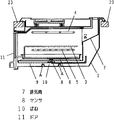
以下、ロースタ部15について説明する。図5は従来の加熱調理器を組み込んだ誘導加熱調理器の断面図であり、特に本発明に関わる加熱調理器としてのロースタ部15周囲の構成を示している。調理庫2内部に調理用ヒータとして焼き網3の上方から魚の表側を加熱調理する上ヒータ4と、焼き網3の下方から魚の裏側を加熱調理する下ヒータ5を内蔵し、焼き網3は調理庫2内に出し入れ自在に設置された受皿6に載置されている。加熱調理された魚から出てくる水や脂は受皿6に受けられ溜められるように構成されていて、調理庫2底面に漏れないようになっている。
Hereinafter, the
また、調理中に発生する煙や水蒸気は器体外へ通じる排気筒7を通って調理庫2外へ排気される。本従来例ではヒータが焼き網3の上下両方向にある両面焼きロースタとなっているが、焼き網3の上方にしかヒータのない片面焼きロースタでも、特に下ヒータ以外の構成は同じものである。調理庫2底面には受皿6と面で接している部分を設け、その部分に受皿6の温度を間接的に検知するセンサ8が取り付けられている。センサ8は、調理庫2の外側に遮熱用に設けられた遮熱ケース9に固定されたばね10により、調理庫2に圧接されて密着するように設けられている。
Further, smoke and water vapor generated during cooking are exhausted out of the
また、センサ周囲に位置する外郭ケース周囲には、センサ8に冷却風や排気口から浸入
した水がいかないように突起部が設けてある。あるいは外郭の底面にゆるやかな傾斜が設けてある(例えば、特許文献1参照)。
しかしながら、このような従来の構成においては、誤って排気口から外郭内部に浸入した水は勢い余って突起部を乗り越える、あるいは遮熱ケース側を伝ってセンサの下や周辺部に溜まる恐れがあり、また、調理庫内の高さは大きくなる傾向にある一方、外郭の高さは決まっているので、底面に浸入した水を流すのに十分な傾斜をつけられないという場合もあるという課題を有していた。 However, in such a conventional configuration, water that has accidentally entered the inside of the outer shell from the exhaust port may overrun the protrusion, or may accumulate under the sensor or around the heat shield case. Also, while the height of the cooking chamber tends to increase, the height of the outer shell is fixed, so there is a problem that it may not be possible to make a sufficient inclination to flow the water that has entered the bottom. Had.
本発明は、従来の課題を解決するもので、排気口から内部に浸入した水がロースタの底センサ下部周辺に流れて溜まったり、センサに付着して絶縁性が落ちるのを防止する加熱調理器を提供することを目的とする。 SUMMARY OF THE INVENTION The present invention solves the conventional problems, and is a heating cooker that prevents water that has entered the inside from the exhaust port from flowing and collecting around the bottom of the bottom sensor of the roaster, or from being attached to the sensor and degrading insulation. The purpose is to provide.
前記従来の課題を解決するために、本発明の加熱調理器は、一方に開口部のある調理庫と、調理物を載置する焼き網と、焼き網を上面に載置し調理庫に出し入れ自在に設けられた受皿と、焼き網の上方に設けられたヒータと、調理庫内と外気に通じる排気経路を構成する排気筒と、調理庫の開口部を塞ぐドアと、調理庫の温度を検知するセンサと、調理庫の周囲を覆い空気層を設けて断熱する遮熱ケースと、調理庫を含む前記遮熱ケースの周囲を覆い調理器の外郭を形成する外郭ケースよりなる構成において、前記センサは前記遮熱ケースに固定され、ばねにより前記調理庫底面に常時密着させ、前記外郭ケースには内部に浸入した水が前記センサ周辺に行かないように、前記センサを略中心として環状に2重に形成された突起部を設け、突起部の間に形成された平面部に水抜き穴を設けるとともに、2重に設けられた突起部の内側の突起部で形成された平面部の面積より、外側と内側の間に形成された平面部の面積を大きくし、2重に設けられた突起部の内側の突起部の高さを外側の突起部の高さより高くした加熱調理器とすることにより、排気口から内部に浸入した水がセンサ下部周辺に流れて溜まるのを防止することができ、センサに付着して絶縁性が落ちるのを防止することができる。 In order to solve the above-described conventional problems, the heating cooker of the present invention includes a cooking chamber having an opening on one side, a grill net on which food is placed, and a grill net placed on the upper surface and put in and out of the cooking chamber. A saucer provided freely, a heater provided above the grill, an exhaust pipe that constitutes an exhaust path communicating with the inside and outside of the cooking cabinet, a door that closes the opening of the cooking cabinet, and the temperature of the cooking cabinet In a configuration comprising a sensor to be detected, a heat shielding case that covers the periphery of the cooking chamber and insulates by providing an air layer, and an outer case that covers the periphery of the heat shielding case including the cooking chamber and forms the outer shell of the cooker, A sensor is fixed to the heat shield case and is always in close contact with the bottom surface of the cooking chamber by a spring, and the outer case has an annular shape around the sensor so that water that has entered inside does not go around the sensor. Protruding parts that are formed Provided with a drain hole in the flat portion formed between the parts, than the area of the flat portion formed inside the protruding portion of the protrusion provided on the double, formed between the outer and inner plane Water that has entered the interior from the exhaust port by increasing the area of the portion and making the heating cooker in which the height of the inner protrusion of the double protrusion is higher than the height of the outer protrusion. Can be prevented from flowing and collecting around the lower part of the sensor, and it can be prevented that the insulating property is lowered due to adhesion to the sensor.
また、2重に設けられた突起部の内側の突起部で形成された平面部の面積より、外側と内側の間に形成された平面部の面積を大きくしたとすることにより、排気口から内部に浸入した水をセンサの周囲で多く受けられる構成にしたことにより下部周辺に流れて溜まるのをさらに防止することができ、センサに水が付着して絶縁性が落ちるのを防止することができる。 In addition, the area of the plane portion formed between the outside and the inside is made larger than the area of the plane portion formed by the projection portion inside the doubly provided projection portion. It is possible to further prevent the water that has entered the sensor from flowing around the lower part of the sensor and collecting it, and to prevent the water from adhering to the sensor to deteriorate the insulation. .
また、2重に設けられた突起部の内側の突起部の高さを外側の突起部の高さより高くしたとすることにより、排気口から内部に浸入した水が内側の突起部を乗り越えにくくしたもので、センサ下部周辺に水が流れ込むのをさらに防止することができ、センサに水が付着して絶縁性が落ちるのを防止することができる。 In addition, by making the height of the inner protrusion of the double protrusion higher than the height of the outer protrusion, it is difficult for water that has entered the inside from the exhaust port to get over the inner protrusion. Therefore, it is possible to further prevent water from flowing into the periphery of the lower part of the sensor, and it is possible to prevent water from adhering to the sensor and lowering the insulating property.
本発明の加熱調理器は、センサ下部周辺に水が溜まるのを防止することができ、センサに付着して絶縁性が落ちるのを防止することができる。 The heating cooker of the present invention can prevent water from accumulating around the lower part of the sensor, and can prevent adhesion to the sensor and deterioration of insulation.
第1の発明は、調理を行う空間である調理庫と、調理物を載置する焼き網と、前記焼き網を上面に載置し前記調理庫に出し入れ自在に設けられた受皿と、前記焼き網の上方に設
けられたヒータと、前記調理庫内と外気に通じる排気経路を構成する排気筒と、前記調理庫の開口部を塞ぐドアと、調理庫の温度を検知するセンサと、前記調理庫の周囲を覆い空気層を設けて断熱する遮熱ケースと、前記調理庫を含む前記遮熱ケースの周囲を覆い調理器の外郭を形成する外郭ケースと、前記外郭ケース内部を冷却するためのファンとを有し、前記センサは前記遮熱ケースに固定され、ばねにより前記調理庫底面に常時密着させ、前記外郭ケースには内部に浸入した水が前記センサ周辺に行かないように、前記センサを略中心として環状に2重に形成された突起部を設け、突起部の間に形成された平面部に水抜き穴を設けるとともに、2重に設けられた突起部の内側の突起部で形成された平面部の面積より、外側と内側の間に形成された平面部の面積を大きくし、2重に設けられた突起部の内側の突起部の高さを外側の突起部の高さより高くした加熱調理器とすることにより、排気口から内部に浸入した水がセンサ下部周辺に流れて溜まるのを防止することができ、センサに付着して絶縁性が落ちるのを防止することができる。
A first invention is a cooking chamber that is a space for cooking, a grill net for placing a cooked food, a saucer that is placed on the top surface so that the grill net is placed on the upper surface, and can be freely put in and out of the cooking cabinet, and the grill A heater provided above the net; an exhaust pipe that constitutes an exhaust path communicating with the inside and outside of the cooking chamber; a door that closes an opening of the cooking chamber; a sensor that detects the temperature of the cooking chamber; and the cooking A heat insulating case that covers the periphery of the cooking chamber and insulates by providing an air layer, an outer case that covers the periphery of the heat insulating case including the cooking chamber and forms the outer shell of the cooker, and for cooling the inside of the outer case A fan, and the sensor is fixed to the heat shield case, and is always in close contact with the bottom surface of the cooking chamber by a spring, and the outer case does not allow water that has entered inside to go around the sensor. Is formed in an annular shape around the center A protrusion provided which, Rutotomoni provided drain hole in the flat portion formed between the protruding portions, than the area of the flat portion formed inside the protruding portion of the protrusion provided on the double outer By increasing the area of the flat part formed between the inner side and the inner side, and making the height of the inner protrusion part of the double protrusion part higher than the height of the outer protrusion part, In addition, it is possible to prevent water that has entered the inside from the exhaust port from flowing around the lower part of the sensor and collecting it, and it is possible to prevent adhesion to the sensor and deterioration of insulation.
また、2重に設けられた突起部の内側の突起部で形成された平面部の面積より、外側と内側の間に形成された平面部の面積を大きくしたとすることにより、排気口から内部に浸入した水をセンサの周囲で多く受けられる構成にしたことにより下部周辺に流れて溜まるのをさらに防止することができ、センサに水が付着して絶縁性が落ちるのを防止することができる。 In addition, the area of the plane portion formed between the outside and the inside is made larger than the area of the plane portion formed by the projection portion inside the doubly provided projection portion. It is possible to further prevent the water that has entered the sensor from flowing around the lower part of the sensor and collecting it, and to prevent the water from adhering to the sensor to deteriorate the insulation. .
また、2重に設けられた突起部の内側の突起部の高さを外側の突起部の高さより高くしたとすることにより、排気口から内部に浸入した水が内側の突起部を乗り越えにくくしたもので、センサ下部周辺に水が流れ込むのをさらに防止することができ、センサに水が付着して絶縁性が落ちるのを防止することができる。 In addition, by making the height of the inner protrusion of the double protrusion higher than the height of the outer protrusion, it is difficult for water that has entered the inside from the exhaust port to get over the inner protrusion. Therefore, it is possible to further prevent water from flowing into the periphery of the lower part of the sensor, and it is possible to prevent water from adhering to the sensor and lowering the insulating property.
第2の発明は、調理を行う空間である調理庫と、調理物を載置する焼き網と、前記焼き網を上面に載置し前記調理庫に出し入れ自在に設けられた受皿と、前記焼き網の上方に設けられたヒータと、前記調理庫内と外気に通じる排気経路を構成する排気筒と、前記調理庫の開口部を塞ぐドアと、調理庫の温度を検知するセンサと、前記調理庫の周囲を覆い空気層を設けて断熱する遮熱ケースと、前記調理庫を含む前記遮熱ケースの周囲を覆い調理器の外郭を形成する外郭ケースと、前記外郭ケース内部を冷却するためのファンとを有し、前記センサは前記外郭ケースには内部に浸入した水が前記センサ周辺に行かないように、前記センサを略中心として環状に2重に形成された突起部を設け、突起部の間に形成された平面部に水抜き穴を設けるとともに、外郭に環状に設けられた外側の突起部の外側の位置に、遮熱ケースより下方に向け環状に突起部を形成したとすることにより、遮熱ケースを伝って流れてきた水がセンサ近辺に行くのを防止することができ、センサに水が付着して絶縁性が落ちるのを防止することができる。 A second aspect of the present invention is a cooking chamber which is a space for cooking, a grill net on which a food is placed, a saucer which is placed on the top surface of the grill net so as to be freely put in and out of the cooking chamber, and the grill A heater provided above the net; an exhaust pipe that constitutes an exhaust path communicating with the inside and outside of the cooking chamber; a door that closes an opening of the cooking chamber; a sensor that detects the temperature of the cooking chamber; and the cooking A heat insulating case that covers the periphery of the cooking chamber and insulates by providing an air layer, an outer case that covers the periphery of the heat insulating case including the cooking chamber and forms the outer shell of the cooker, and for cooling the inside of the outer case A fan, and the sensor is provided with a protrusion formed in an annular shape around the sensor so that water that has entered the outer case does not go to the periphery of the sensor. A drain hole is provided in the flat part formed between Both the outer position outside the projection portion provided annularly shell, by the forming the protruding portion annularly downward from heat shield case, the water which has flowed along the heat shield case sensor It can prevent going to the vicinity, and can prevent that a water adheres to a sensor and insulation falls.
第3の発明は、調理を行う空間である調理庫と、調理物を載置する焼き網と、前記焼き網を上面に載置し前記調理庫に出し入れ自在に設けられた受皿と、前記焼き網の上方に設けられたヒータと、前記調理庫内と外気に通じる排気経路を構成する排気筒と、前記調理庫の開口部を塞ぐドアと、調理庫の温度を検知するセンサと、前記調理庫の周囲を覆い空気層を設けて断熱する遮熱ケースと、前記調理庫を含む前記遮熱ケースの周囲を覆い調理器の外郭を形成する外郭ケースと、前記外郭ケース内部を冷却するためのファンとを有し、前記センサは前記外郭ケースには内部に浸入した水が前記センサ周辺に行かないように、前記センサを略中心として環状に2重に形成された突起部を設け、突起部の間に形成された平面部に水抜き穴を設けるとともに、遮熱ケース後方の外郭ケース底面に垂直あるいは外郭後面に向かって上方に傾斜した浸入防止壁を設けたとすることにより、排気口から誤って流れ込んだ水の勢いをいったん止めて突起部の外側に水を流すことにより、センサ下部周辺に流れて溜まるのをさらに防止することができ、センサに水が付着して絶縁性が落ちるのを防止することができる。 A third aspect of the invention is a cooking chamber that is a space for cooking, a grill that places the food, a saucer that is placed on the top and is freely put in and out of the cooking chamber, and the grill A heater provided above the net; an exhaust pipe that constitutes an exhaust path communicating with the inside and outside of the cooking chamber; a door that closes an opening of the cooking chamber; a sensor that detects the temperature of the cooking chamber; and the cooking A heat insulating case that covers the periphery of the cooking chamber and insulates by providing an air layer, an outer case that covers the periphery of the heat insulating case including the cooking chamber and forms the outer shell of the cooker, and for cooling the inside of the outer case A fan, and the sensor is provided with a protrusion formed in an annular shape around the sensor so that water that has entered the outer case does not go to the periphery of the sensor. A drain hole is provided in the flat part formed between Both by the provided entry preventing wall which is inclined upwardly towards the vertical or outer rear surface outer case bottom surface of the rear heat shield case, outside the protruding portion once you stop the momentum of the flowing accidentally from the outlet water By flowing water, it is possible to further prevent the water from flowing and collecting around the lower part of the sensor, and to prevent water from adhering to the sensor and lowering the insulating property.
以下、本発明の実施の形態について図面を参照して説明する。なお、本実施の形態では、加熱調理器を誘導加熱調理器のロースタ部として組み込んだ場合について説明する。 Hereinafter, embodiments of the present invention will be described with reference to the drawings. In addition, this Embodiment demonstrates the case where a heating cooker is integrated as a roaster part of an induction heating cooking appliance.
(実施の形態1)
図1は本発明の第1の実施の形態における、組み込み式誘導加熱調理器の概略図であり、図2はこの誘導加熱調理器をキャビネット23に組み込んだ状態図である。
(Embodiment 1)
FIG. 1 is a schematic view of a built-in induction heating cooker according to the first embodiment of the present invention, and FIG. 2 is a state diagram in which the induction heating cooker is incorporated in a
組み込み式の加熱調理器の場合、キャビネット23の天板にあけられた穴の内側に調理器全体を落とし込んで、キャビネット23の天板に吊り下げるようになっている。このようにキャビネット23内部に調理器を落とし込んで設置するが、調理器自体の吸排気のリーク防止、調理器下に組み込まれたオーブンや食器洗い器などからの熱の影響を極力減らすためにキャビネット23内部からの吸気、キャビネット23内部への排気をしないようにしてある。このため、器体内部の冷却のための吸気と排気は、使用者に対して最も違和感の少ないトッププレート13奥側に設けられた吸気口20と排気口19により行われる。
In the case of a built-in heating cooker, the entire cooker is dropped inside a hole formed in the top plate of the
以下にロースタ部について説明する。なお、本実施の形態の構成は従来例の構成とほぼ同じであるため、その説明は省略し、主に相違点を中心に説明する。 The roaster section will be described below. Since the configuration of the present embodiment is almost the same as the configuration of the conventional example, the description thereof will be omitted and the description will mainly focus on the differences.
図3は本発明の実施の形態1における誘導加熱調理器の断面図である。受皿6は、調理庫2内部に摺動自在に設けられており、調理庫2底面につけられたレール21の上を受皿6の底面をドア11と一緒に滑らせて摺動させている。受皿6は、その上方に載せられた焼き網3上に置かれた調理物から出てくる水や脂を受け、それ以外の調理庫2内部に溢さないようにしている。
FIG. 3 is a cross-sectional view of the induction heating cooker according to
また両面焼きのロースタの場合、受皿6と焼き網3の間にヒータが設けられ、受皿6の温度上昇が著しいことがある。このような状況に対して、あらかじめ受皿6に水を溜めて調理をすると受皿6の温度上昇を抑えることができる。受皿6の温度が上昇すると溜められている水や脂が加熱され、温度が上がるにつれ煙の発生量が多くなる。
In the case of a double-sided roaster, a heater is provided between the
さらに加熱が進むと脂の気化がすすみ、下ヒータ5に直接脂が垂れて一瞬火が付き、それが受皿6の油に引火する恐れもある。そのため、受皿6の温度を検知するための手段が必要となってくる。
As the heating further progresses, the vaporization of the fat progresses, and the fat drips directly on the
受皿6の中央付近には摺動させるためのレール21以外に受皿6と調理庫2底面が接する面がある。調理庫2外側からこの面にセンサ8を取り付けて受皿6の温度を検知できるようにしてある。センサ8の取り付け方法は、調理庫2底面に穴をあけて直接受皿6の温度を検知することも考えられるが、調理庫2内部は調理物より発生する脂が付着してセンサ8に固着し、検知温度に大きな誤差を与える可能性があるため、調理庫2外側から間接的に受皿6の温度を検知するようにしている。
In the vicinity of the center of the
調理庫2の外側には、調理庫2内部の熱を断熱するために空気層を設けて遮熱ケース9が設けられている。センサ8はこの遮熱ケース9に固定されており、ばね10によりセンサ8と調理庫2底面が絶えず密着しているようになっている。この密着面には熱伝導に優れたグリスを塗ることにより、さらにセンサ8の受感性を良くしている。
In order to insulate the heat inside the
遮熱ケース9の外側には外郭ケース1がある。外郭ケース1は外郭を構成する板金であるため、使用者が誤って触れた場合に火傷の恐れがないような温度まで冷却する必要があるので、調理中は外郭ケース1と遮熱ケース9の間には常に風を流して冷却し続けるよう
になっている。
There is an
図4は本発明の実施の形態1における加熱調理器の外郭ケース底面の形状図である。図4に示すようにセンサ8の直下近傍の外郭ケース1には、センサ8を略中心として環状に2重に形成された突起部を設けてあり、突起部の間に形成された平面部には水抜き穴12が設けてある。2重に設けられた突起部の内側の突起部a24の高さは、外側の突起部b25の高さより高く、2重に設けられた突起部の内側の突起部a24で形成された平面部の面積より、外側と内側の間に形成された平面部の面積が大きい形状になっている。一方、遮熱ケース9にも、外郭ケース1の外側の突起部b25のさらに外側の位置に、下方に向け環状に突起部c26を形成している。さらに、遮熱ケース後方の外郭ケース1の底面に垂直あるいは外郭ケース1後面に向かって上方に傾斜した浸入防止壁22を設けている。
FIG. 4 is a shape diagram of the bottom surface of the outer case of the cooking device according to
以上のように構成された加熱調理器について、外郭ケース1および遮熱ケース9に設けられた突起部周辺の作用について説明する。
About the heating cooker comprised as mentioned above, the effect | action of the protrusion part provided in the
使用者が調理中に誤ってトッププレート13上に汁物をこぼしてしまい、排気口20より外郭ケース1内部に水が入ってしまった場合、センサ8のリード線を伝ってセンサ8の感度に影響を与えるような物が付着したり、水分で絶縁が不可となってしまう状況が考えられる。
If a user accidentally spills soup on the
浸入した水は、遮熱ケース9後方の外郭ケース1の底面に直角あるいは外郭ケース1後面に向かって上方に傾斜した浸入防止壁22により、その水の流れの勢いを止められるとともに、センサ8部に向かって直接流れ込まないように外側に流され、水の流れの勢いにより突起部を乗り越えるのを防止する役割を果たしている。また、センサ8を略中心として環状に2重に形成されたセンサ8下部周辺の外郭ケース1より上方向きの突起部a24、突起部b25により、外郭ケースに沿ってセンサ8周辺に流れ込んできた水をせき止めるとともに、仮に外側の突起部b25を乗り越えた場合でも、突起部a24と突起部b25との間に形成された平面部に水抜き穴12により、浸入した水を調理器の外部に排出しセンサ下部周辺に溜まるのを防止することができ、センサ8に水が付着して絶縁性が落ちるのを防止することができる。さらに2重に設けられた突起部の内側の突起部a24の高さは、外側の突起部b25の高さより高く、2重に設けられた突起部の内側の突起部a24で形成された平面部の面積より、外側と内側の間に形成された平面部の面積が大きい形状になっているので、内側の突起部a24を乗り越えてセンサ下部周辺に溜まるのをより防止することができる。遮熱ケース9に設けた下方向きの突起部c26により、遮熱ケース9を伝ってくる水も突起部b25外側の外郭ケース1上に落ちるのでセンサ8の下部周辺への浸入を防止することができる。
The ingress water is stopped by the
以上のような構成により、排気口より浸入した水がセンサ8下部周辺に水が溜まったり、水が付着したりして絶縁性が落ちるのを防止することができ、センサ8の性能を良好な状態に維持することができる。
With the configuration as described above, it is possible to prevent the water that has entered from the exhaust port from collecting around the lower part of the
また、センサ8に対する冷却風の影響もできる限り抑えることができるため、センサ8感度が良好となり、常に受皿6の温度を正確に把握でき、受皿6の温度上昇により煙量を抑えることができる。また、水を受皿6に張って調理する方式の場合も、受皿6の水が蒸発してなくなり、受皿6の温度が高くなったことも正確に検知ができる。また、異常状態において調理庫2内で炎が発生した場合においても、素早く温度上昇を検知し、ヒータ4、5の出力を切り、鎮火をすることができる。
In addition, since the influence of the cooling air on the
以上のように、本発明にかかる加熱調理器は、センサ下部周辺に水が溜まるのを防止することができ、センサに付着して絶縁性が落ちるのを防止することができるので、調理庫の温度を検知するセンサを調理庫の下部に備え、ヒータに限らず他の熱源を有する加熱調理器等の用途にも適用できる。 As described above, the heating cooker according to the present invention can prevent water from accumulating around the lower part of the sensor, and can prevent adhesion to the sensor and deterioration of insulation. The sensor which detects temperature is provided in the lower part of a cooking chamber, and it can apply also to uses, such as a heating cooker which has not only a heater but another heat source.
1 外郭ケース
2 調理庫
3 焼き網
4 上ヒータ
5 下ヒータ
6 受皿
7 排気筒
8 センサ
9 遮熱ケース
11 ドア
12 水抜き穴
14 加熱コイル
15 ロースタ部
16 操作部
17 制御基板
18 ファン
22 浸入防止壁
24 突起部a
25 突起部b
26 突起部c
DESCRIPTION OF
25 Projection b
26 Protrusion c
Claims (3)
記外郭ケースには内部に浸入した水が前記センサ周辺に行かないように、前記センサを略中心として環状に2重に形成された突起部を設け、突起部の間に形成された平面部に水抜き穴を設けるとともに、遮熱ケース後方の外郭ケース底面に垂直あるいは外郭後面に向かって上方に傾斜した浸入防止壁を設けた加熱調理器。
A cooking chamber that is a space for cooking, a grill that places the food, a tray that is placed on the top and that can be put into and out of the cooking chamber, and a grill that is provided above the grill. A heater, an exhaust pipe constituting an exhaust path communicating with the inside and outside of the cooking cabinet, a door for closing the opening of the cooking cabinet, a sensor for detecting the temperature of the cooking cabinet, and air surrounding the cooking cabinet A heat insulating case for insulating by providing a layer, an outer case for covering the periphery of the heat insulating case including the cooking chamber to form an outer shell of the cooker, and a fan for cooling the outer case interior, In the outer case, the sensor is provided with a protrusion formed in an annular shape around the sensor so that water that has entered the outer periphery does not go around the sensor, and is formed between the protrusions. the flat surface portion provided weep holes Rutotomoni thermal barrier Pressurized heat cooker provided with entry preventing wall which is inclined upwardly in the outer bottom of the case over the scan backwards toward the vertical or outer rear surface.
Priority Applications (1)
| Application Number | Priority Date | Filing Date | Title |
|---|---|---|---|
| JP2007175820A JP4946673B2 (en) | 2007-07-04 | 2007-07-04 | Cooker |
Applications Claiming Priority (1)
| Application Number | Priority Date | Filing Date | Title |
|---|---|---|---|
| JP2007175820A JP4946673B2 (en) | 2007-07-04 | 2007-07-04 | Cooker |
Publications (2)
| Publication Number | Publication Date |
|---|---|
| JP2009011522A JP2009011522A (en) | 2009-01-22 |
| JP4946673B2 true JP4946673B2 (en) | 2012-06-06 |
Family
ID=40353163
Family Applications (1)
| Application Number | Title | Priority Date | Filing Date |
|---|---|---|---|
| JP2007175820A Expired - Fee Related JP4946673B2 (en) | 2007-07-04 | 2007-07-04 | Cooker |
Country Status (1)
| Country | Link |
|---|---|
| JP (1) | JP4946673B2 (en) |
Families Citing this family (1)
| Publication number | Priority date | Publication date | Assignee | Title |
|---|---|---|---|---|
| CN110811302B (en) * | 2018-08-13 | 2025-02-07 | 宁波方太厨具有限公司 | Household appliance with double inner tank |
Family Cites Families (3)
| Publication number | Priority date | Publication date | Assignee | Title |
|---|---|---|---|---|
| JPH11321446A (en) * | 1998-05-08 | 1999-11-24 | Ichikoh Ind Ltd | Vehicular device |
| JP3562452B2 (en) * | 2000-08-29 | 2004-09-08 | 松下電器産業株式会社 | Roaster |
| JP3899978B2 (en) * | 2002-03-28 | 2007-03-28 | 松下電器産業株式会社 | Cooker |
-
2007
- 2007-07-04 JP JP2007175820A patent/JP4946673B2/en not_active Expired - Fee Related
Also Published As
| Publication number | Publication date |
|---|---|
| JP2009011522A (en) | 2009-01-22 |
Similar Documents
| Publication | Publication Date | Title |
|---|---|---|
| US8333183B2 (en) | Cooking range including an air circulation mechanism | |
| JP5202922B2 (en) | Built-in equipment | |
| JP3899978B2 (en) | Cooker | |
| JP5833073B2 (en) | Cooker | |
| JP6298991B2 (en) | Cooker | |
| JP6365882B2 (en) | Cooker | |
| JP2020125867A (en) | Heating cooker | |
| JP5104420B2 (en) | Cooker | |
| JP2003284648A5 (en) | ||
| JP2016126840A5 (en) | ||
| JP4946673B2 (en) | Cooker | |
| JP6022017B2 (en) | Cooker | |
| JP2005261613A (en) | Door and cooker using it | |
| JP2010277751A (en) | Induction heating cooker | |
| JP5663966B2 (en) | Electric cooker | |
| JP2012223238A (en) | rice cooker | |
| JP6415475B2 (en) | Induction heating cooker | |
| KR101531062B1 (en) | Oven range including a duct unit | |
| JP6441584B2 (en) | Cooker | |
| KR20080064382A (en) | Built-in cookers and their installation utensils | |
| JP4225311B2 (en) | Induction heating cooker | |
| KR200441266Y1 (en) | case structure in a griddle | |
| KR101531061B1 (en) | An oven range | |
| KR101465068B1 (en) | Built-in type gas cook top | |
| JP3937410B2 (en) | Cooker |
Legal Events
| Date | Code | Title | Description |
|---|---|---|---|
| A621 | Written request for application examination |
Free format text: JAPANESE INTERMEDIATE CODE: A621 Effective date: 20091215 |
|
| RD01 | Notification of change of attorney |
Free format text: JAPANESE INTERMEDIATE CODE: A7421 Effective date: 20100113 |
|
| A131 | Notification of reasons for refusal |
Free format text: JAPANESE INTERMEDIATE CODE: A131 Effective date: 20111101 |
|
| A521 | Written amendment |
Free format text: JAPANESE INTERMEDIATE CODE: A523 Effective date: 20111213 |
|
| TRDD | Decision of grant or rejection written | ||
| A01 | Written decision to grant a patent or to grant a registration (utility model) |
Free format text: JAPANESE INTERMEDIATE CODE: A01 Effective date: 20120207 |
|
| A01 | Written decision to grant a patent or to grant a registration (utility model) |
Free format text: JAPANESE INTERMEDIATE CODE: A01 |
|
| A61 | First payment of annual fees (during grant procedure) |
Free format text: JAPANESE INTERMEDIATE CODE: A61 Effective date: 20120220 |
|
| FPAY | Renewal fee payment (event date is renewal date of database) |
Free format text: PAYMENT UNTIL: 20150316 Year of fee payment: 3 |
|
| FPAY | Renewal fee payment (event date is renewal date of database) |
Free format text: PAYMENT UNTIL: 20150316 Year of fee payment: 3 |
|
| LAPS | Cancellation because of no payment of annual fees |