JP4945791B2 - Unilateral bone anchor - Google Patents
Unilateral bone anchor Download PDFInfo
- Publication number
- JP4945791B2 JP4945791B2 JP2009291283A JP2009291283A JP4945791B2 JP 4945791 B2 JP4945791 B2 JP 4945791B2 JP 2009291283 A JP2009291283 A JP 2009291283A JP 2009291283 A JP2009291283 A JP 2009291283A JP 4945791 B2 JP4945791 B2 JP 4945791B2
- Authority
- JP
- Japan
- Prior art keywords
- strut
- joint
- axis
- fixator
- column
- Prior art date
- Legal status (The legal status is an assumption and is not a legal conclusion. Google has not performed a legal analysis and makes no representation as to the accuracy of the status listed.)
- Expired - Fee Related
Links
- 210000000988 bone and bone Anatomy 0.000 title claims description 93
- 239000002131 composite material Substances 0.000 claims description 57
- 230000007246 mechanism Effects 0.000 claims description 43
- 150000001875 compounds Chemical class 0.000 claims description 30
- 230000036244 malformation Effects 0.000 description 26
- 230000009467 reduction Effects 0.000 description 17
- 239000012634 fragment Substances 0.000 description 13
- 238000000034 method Methods 0.000 description 11
- 239000003638 chemical reducing agent Substances 0.000 description 8
- 241000723353 Chrysanthemum Species 0.000 description 6
- 235000007516 Chrysanthemum Nutrition 0.000 description 6
- 239000000463 material Substances 0.000 description 5
- 229910000831 Steel Inorganic materials 0.000 description 4
- 230000000712 assembly Effects 0.000 description 4
- 238000000429 assembly Methods 0.000 description 4
- 229920001971 elastomer Polymers 0.000 description 4
- 125000006850 spacer group Chemical group 0.000 description 4
- 239000010935 stainless steel Substances 0.000 description 4
- 239000010959 steel Substances 0.000 description 4
- 235000008526 Galium odoratum Nutrition 0.000 description 3
- 210000003423 ankle Anatomy 0.000 description 3
- 239000000806 elastomer Substances 0.000 description 3
- 229910000838 Al alloy Inorganic materials 0.000 description 2
- 244000186140 Asperula odorata Species 0.000 description 2
- 206010070918 Bone deformity Diseases 0.000 description 2
- 208000027418 Wounds and injury Diseases 0.000 description 2
- XAGFODPZIPBFFR-UHFFFAOYSA-N aluminium Chemical compound [Al] XAGFODPZIPBFFR-UHFFFAOYSA-N 0.000 description 2
- 229910052782 aluminium Inorganic materials 0.000 description 2
- 230000008901 benefit Effects 0.000 description 2
- 229910001220 stainless steel Inorganic materials 0.000 description 2
- 239000002023 wood Substances 0.000 description 2
- 210000000707 wrist Anatomy 0.000 description 2
- 229910001369 Brass Inorganic materials 0.000 description 1
- 206010062344 Congenital musculoskeletal anomaly Diseases 0.000 description 1
- 244000258271 Galium odoratum Species 0.000 description 1
- 241001272720 Medialuna californiensis Species 0.000 description 1
- 206010061363 Skeletal injury Diseases 0.000 description 1
- 230000001154 acute effect Effects 0.000 description 1
- 239000000853 adhesive Substances 0.000 description 1
- 230000001070 adhesive effect Effects 0.000 description 1
- 230000002411 adverse Effects 0.000 description 1
- 239000010951 brass Substances 0.000 description 1
- 230000008859 change Effects 0.000 description 1
- 230000001684 chronic effect Effects 0.000 description 1
- 238000004590 computer program Methods 0.000 description 1
- 230000008602 contraction Effects 0.000 description 1
- 230000008878 coupling Effects 0.000 description 1
- 238000010168 coupling process Methods 0.000 description 1
- 238000005859 coupling reaction Methods 0.000 description 1
- 230000006378 damage Effects 0.000 description 1
- 239000003814 drug Substances 0.000 description 1
- 230000000694 effects Effects 0.000 description 1
- 238000007373 indentation Methods 0.000 description 1
- 208000014674 injury Diseases 0.000 description 1
- 230000003601 intercostal effect Effects 0.000 description 1
- 230000000399 orthopedic effect Effects 0.000 description 1
- 230000036316 preload Effects 0.000 description 1
- 230000008569 process Effects 0.000 description 1
- 230000008439 repair process Effects 0.000 description 1
- 230000004044 response Effects 0.000 description 1
- 230000002441 reversible effect Effects 0.000 description 1
- 230000035939 shock Effects 0.000 description 1
Images


Classifications
-
- A—HUMAN NECESSITIES
- A61—MEDICAL OR VETERINARY SCIENCE; HYGIENE
- A61B—DIAGNOSIS; SURGERY; IDENTIFICATION
- A61B17/00—Surgical instruments, devices or methods
- A61B17/56—Surgical instruments or methods for treatment of bones or joints; Devices specially adapted therefor
- A61B17/58—Surgical instruments or methods for treatment of bones or joints; Devices specially adapted therefor for osteosynthesis, e.g. bone plates, screws or setting implements
- A61B17/60—Surgical instruments or methods for treatment of bones or joints; Devices specially adapted therefor for osteosynthesis, e.g. bone plates, screws or setting implements for external osteosynthesis, e.g. distractors, contractors
- A61B17/64—Devices extending alongside the bones to be positioned
- A61B17/6458—Devices extending alongside the bones to be positioned with pin-clamps fixed at ends of connecting element
-
- A—HUMAN NECESSITIES
- A61—MEDICAL OR VETERINARY SCIENCE; HYGIENE
- A61B—DIAGNOSIS; SURGERY; IDENTIFICATION
- A61B17/00—Surgical instruments, devices or methods
- A61B17/56—Surgical instruments or methods for treatment of bones or joints; Devices specially adapted therefor
- A61B17/58—Surgical instruments or methods for treatment of bones or joints; Devices specially adapted therefor for osteosynthesis, e.g. bone plates, screws or setting implements
- A61B17/60—Surgical instruments or methods for treatment of bones or joints; Devices specially adapted therefor for osteosynthesis, e.g. bone plates, screws or setting implements for external osteosynthesis, e.g. distractors, contractors
- A61B17/66—Alignment, compression or distraction mechanisms
-
- A—HUMAN NECESSITIES
- A61—MEDICAL OR VETERINARY SCIENCE; HYGIENE
- A61B—DIAGNOSIS; SURGERY; IDENTIFICATION
- A61B17/00—Surgical instruments, devices or methods
- A61B17/56—Surgical instruments or methods for treatment of bones or joints; Devices specially adapted therefor
- A61B2017/564—Methods for bone or joint treatment
-
- A—HUMAN NECESSITIES
- A61—MEDICAL OR VETERINARY SCIENCE; HYGIENE
- A61B—DIAGNOSIS; SURGERY; IDENTIFICATION
- A61B90/00—Instruments, implements or accessories specially adapted for surgery or diagnosis and not covered by any of the groups A61B1/00 - A61B50/00, e.g. for luxation treatment or for protecting wound edges
- A61B90/36—Image-producing devices or illumination devices not otherwise provided for
- A61B90/37—Surgical systems with images on a monitor during operation
- A61B2090/376—Surgical systems with images on a monitor during operation using X-rays, e.g. fluoroscopy
-
- A—HUMAN NECESSITIES
- A61—MEDICAL OR VETERINARY SCIENCE; HYGIENE
- A61B—DIAGNOSIS; SURGERY; IDENTIFICATION
- A61B34/00—Computer-aided surgery; Manipulators or robots specially adapted for use in surgery
- A61B34/10—Computer-aided planning, simulation or modelling of surgical operations
Landscapes
- Health & Medical Sciences (AREA)
- Orthopedic Medicine & Surgery (AREA)
- Life Sciences & Earth Sciences (AREA)
- Surgery (AREA)
- Medical Informatics (AREA)
- Engineering & Computer Science (AREA)
- Biomedical Technology (AREA)
- Heart & Thoracic Surgery (AREA)
- Nuclear Medicine, Radiotherapy & Molecular Imaging (AREA)
- Molecular Biology (AREA)
- Animal Behavior & Ethology (AREA)
- General Health & Medical Sciences (AREA)
- Public Health (AREA)
- Veterinary Medicine (AREA)
- Surgical Instruments (AREA)
- Orthopedics, Nursing, And Contraception (AREA)
- Accommodation For Nursing Or Treatment Tables (AREA)
Description
本発明は、片側骨固定器に関するものであり、より具体的には、さまざまな6自由度筋骨格奇形に対し、奇形矯正過程で大ざっぱな操作及び精密な操作の両方によって対処する片側骨固定器に関するものである。 The present invention relates to unilateral bone anchors, and more specifically to unilateral bone anchors that deal with various six-degree-of-freedom musculoskeletal malformations by both rough and precise manipulations during the malformation correction process. It is about.
(関連する特許出願に関する申立)
この特許本出願は、2002年9月17日に出願され、発明の名称が片側骨固定器である米国特許仮出願第60/411,291号、及び2002年11月14日に出願され、発明の名称が片側骨固定器方法である米国特許仮出願第60/426,439号に対して35U.S.C.§119による優先権を主張している。上記仮出願は、参照により本明細書に全て組み込まれる。
(Request for related patent application)
This patent application was filed on Sep. 17, 2002, and the name of the invention was US Patent Provisional Application No. 60 / 411,291, which was a unilateral bone anchor, and filed on Nov. 14, 2002. US Patent Provisional Application No. 60 / 426,439, whose name is the unilateral bone anchor method, is 35 U.S. S. C. Claims priority according to §119. The provisional application is hereby incorporated by reference in its entirety.
(発明の背景)
整形外科の医療では、医師が、所定の骨格の傷害又は奇形を外付け骨固定器を用いて直さなくてはならないことがよくある。このような奇形は、急性であることも、慢性であることもあり、短期間で直せることも、長期をかけて直すこともある。これらの骨固定器は、個々の骨片に取り付けられたピン又はワイヤと、外付け構造フレームとを用いて骨片をある程度まで一直線に揃え、又は固定し、傷害の治療や、奇形の矯正を補助するものである。骨固定器を患者に取り付けると、骨固定器は、力を加えて、骨片を医師が定めた形状に維持する。多くの場合、医師は、時間と共に骨片の配置を徐々に調整しなければならず、この場合、6自由度で調整できて、骨片を解剖学上の正しい状態に確実に配置できることが最も望ましい。
(Background of the Invention)
In orthopedic medicine, doctors often have to repair certain skeletal injuries or malformations using external bone anchors. Such malformations can be acute or chronic and can be corrected in a short period of time or can be corrected over a long period of time. These bone anchors use pins or wires attached to individual bone fragments and an external structural frame to align or fix the bone fragments to a certain extent to treat injuries and correct malformations. It is to assist. When the bone anchor is attached to the patient, the bone anchor applies force to maintain the bone fragment in the shape defined by the physician. In many cases, the physician has to gradually adjust the placement of the bone fragment over time, in which case it can be adjusted with 6 degrees of freedom, ensuring that the bone fragment is placed in the correct anatomical state. desirable.
筋骨格の奇形を取り扱ういろいろな器機及び方法が当技術分野では公知である。これらの装置は、構造がいろいろであるが、一般に、2つの大きなカテゴリー、すなわち、円環型機器と、片側型機器とに分類される。円環型機器のカテゴリーの一例としては、イリザロフ型システムがある。このイリザロフ型システムは、2つのリングを有しており、この2つのリングは、複数のまっすぐな支柱によって連結されており、これらの支柱は、各支柱の各端部に固定連結部又はヒンジ連結部を備えている。スペースフレームと呼ばれる機器は、2つのリングを有し、この2つのリングは、6つの真っ直ぐな支柱によって連結されており、この6つの支柱は各端部に6脚配列に配置された球継ぎ手を有している。スペースフレームには、例えばスチュワートフレームがある。スペースフレームは、元々のイリザロフの概念が進化したものである。他の具体例には、リングを組み合わせたものを片側機器とみなせるものに取り付けたものがある。このような構造のものは、ハイブリット機器と一般に呼ばれている。 Various devices and methods for handling musculoskeletal malformations are known in the art. These devices vary in structure, but generally fall into two broad categories: ring-type equipment and single-sided equipment. An example of the category of toroidal devices is the Ilizarov system. The Ilizarov system has two rings, which are connected by a plurality of straight struts that are fixed or hinged to each end of each strut. Department. A device called a space frame has two rings, which are connected by six straight struts that have ball joints arranged in a six-legged arrangement at each end. Have. An example of the space frame is a Stewart frame. The space frame is an evolution of the original Ilizarov concept. Other specific examples include those in which a combination of rings is attached to what can be regarded as one-sided equipment. Such a structure is generally called a hybrid device.
イリザロフ型機器は、矯正する必要がある奇形に基づいて、つまり、特定の患者及びその患者の具体的な奇形に対して組み立てられる。ヒンジ及び支柱を加えて、具体的な事例におけるそれぞれの奇形の度合いに対処するのである。イリザロフ型機器は、各調整がただ一つの奇形の度合いに関係する点で、たびたび、シリアルマニピュレータと呼ばれている。このようなアプローチでは、今現在の奇形に基づいてフレームを組み立てる必要がある。このため、使用法はかなり単純明快であるが、無数ともなりうる複数の形状からなる複雑な一セットとなる可能性がある。スペースフレームは、リングや支柱を異なる大きさのものとすることができるにしても概念的には一つの形状の機器である。スチュアートフレーム型スペースフレームは、6つの支柱のどれをどのように調整しても6自由度すべてが変化してしまう点から、たびたび、パラレルマニピュレータと呼ばれている。この特徴からスチュワートフレーム型の機器は、あまり直感的に使うことができない。奇形を直すための調整を行うユーザーを導くコンピュータプログラムが多くの場合に必要である。 The Ilizarov type device is assembled based on the malformation that needs to be corrected, that is, for a particular patient and the patient's specific malformation. Add hinges and struts to address each degree of malformation in the specific case. Ilizarov type devices are often called serial manipulators because each adjustment is related to a single degree of malformation. Such an approach requires the frame to be assembled based on current malformations. For this reason, the usage is fairly simple and clear, but can be a complex set of shapes that can be innumerable. A space frame is conceptually a piece of equipment even though the rings and struts can be of different sizes. The Stuart frame type space frame is often called a parallel manipulator because all six degrees of freedom change regardless of how any of the six columns are adjusted. Because of this feature, Stewart frame type devices cannot be used very intuitively. Computer programs that guide the user to make adjustments to correct the malformation are often necessary.
片側型の機器のカテゴリーにはいくつかの機器がある。これらの機器は、基本的に一連の直交二次元ヒンジ又は球継ぎ手からなり、場合によっては、特定の位置に固定できるスライダーからなる。一般に、これらの機器は、骨片を特定の配置に固定するのに使用できるが、その配置を徐々に、かつ、精密に動かすことはできない。なぜならば、この器機の継ぎ手に、各ヒンジ又はスライダーと連結された直接調整用装置がないからである。それどころか、この機器の継ぎ手を緩め、そして、器機上で全体を大きく操作しなければならない。イリザロフ型円環骨固定器と同様に、これらの機器のいくつかは、特定の自由度で動くことができる。これは、一般に伸縮であり、ときとして、ある軸回りの一回転である。しかしながら、これらの機器は、多くの場合に、奇形の特徴しだいで特定の位置で組み立てたり取り付けたりする必要がある。このような要求は、これら機器の使い方を複雑にするものであり、医師が一般に遭遇する奇形の範囲を取り扱うのに複数の形状が必要にもなる。従来技術の機器でその機器が患者に取り付けられている間に6自由度で微調整ができるものはない。 There are several devices in the category of single-sided devices. These devices basically consist of a series of orthogonal two-dimensional hinges or ball joints, and in some cases, a slider that can be fixed in a specific position. In general, these devices can be used to fix bone fragments in a particular arrangement, but the arrangement cannot be moved gradually and precisely. This is because there is no direct adjustment device connected to each hinge or slider at the joint of this device. On the contrary, the fittings on this device must be loosened and the whole machine manipulated. Similar to the Ilizarov torus, some of these devices can move with a certain degree of freedom. This is generally expansion and contraction, sometimes a single rotation about an axis. However, these devices often need to be assembled and installed in specific locations depending on the characteristics of the malformation. Such a requirement complicates the use of these devices and also requires multiple shapes to handle the range of malformations commonly encountered by physicians. None of the prior art devices can be fine tuned with 6 degrees of freedom while the device is attached to the patient.
6自由度とは、3つの直交軸に関する移動とその3つの軸のそれぞれの回りの回転とをいう。これら6つの自由度は、一般に、前後、上下、左右、ピッチ、ロール、及びヨーと呼ばれる。 Six degrees of freedom refers to movement about three orthogonal axes and rotation about each of the three axes. These six degrees of freedom are commonly referred to as front and rear, top and bottom, left and right, pitch, roll, and yaw.
また、スペースフレーム又は片側骨固定器を大きく操作して、奇形した骨片を奇形矯正処置の最初に適切な位置に配置することができる。しかしながら、医師は、奇形を適切に矯正するために、奇形矯正処置の間じゅう、骨固定器の位置を変えることが必要な場合がある。典型的なスペースフレーム及び片側骨固定器は、奇形矯正処置中に医師が骨固定器の位置を調整する必要がある度に患者から外す、すなわち、これらの機器を患者に取り付けたままで緩めて、大きく調整する必要がある。既存の機器のこのような限界の原因の一つは、これらの機器の調整機構では、微調整を行うのに十分な機械的倍率、すなわち、移動範囲が得られないということである。このように骨固定器を所定位置に微調整できないということが、これら骨固定器の有用性を低下させているのである。 Alternatively, the space frame or unilateral bone anchor can be manipulated to place the deformed bone fragment in the proper position at the beginning of the deformity correction procedure. However, the physician may need to reposition the bone anchor throughout the malformation procedure in order to properly correct the malformation. Typical space frames and unilateral bone anchors are removed from the patient each time the doctor needs to adjust the position of the bone anchor during the malformation procedure, i.e., loosen these devices attached to the patient, It is necessary to make large adjustments. One of the causes of such limitations of existing equipment is that the mechanical adjustment mechanism of these equipments does not provide a mechanical magnification sufficient for fine adjustment, that is, a moving range. The fact that the bone anchors cannot be finely adjusted to a predetermined position in this way reduces the usefulness of these bone anchors.
必要なのは、6自由度の筋骨格奇形、すなわち、前後方向(AP)、横方向、及び軸方向のずれ、並びにアンギュレーション(angulations)又はその任意のサブセットを有する奇形に対処できる機器である。求められている機器は、奇形部に任意の特定の位置(向き)において実用的に配置できなければならず、かつ、同一機器で複数の形態のものを必要とすることなく奇形を解剖学的状態まで低減できなければならない。さらに、この機器は、高い機械的倍率の調整機構を用いて、奇形が深刻な場合には奇形を大きく操作でき、そしてさらに、この機器を患者に取り付けたままで奇形矯正処置中にさらに精密な微調整を施せることができるものでなければならない。 What is needed is a device that can cope with musculoskeletal malformations with 6 degrees of freedom, ie, malformations with anteroposterior (AP), lateral and axial deviations, and angulations or any subset thereof. The required equipment must be able to be practically placed at any specific position (orientation) in the malformation, and anatomical deformities can be achieved without requiring multiple forms of the same equipment It must be possible to reduce to a state. In addition, the device uses a high mechanical magnification adjustment mechanism to greatly manipulate the malformation if the malformation is severe, and, in addition, the device can remain attached to the patient with a finer precision during the malformation procedure. It must be able to be adjusted.
(発明の開示)
本発明は、片側外付け骨固定器を提供するものであり、この骨固定器は、奇形部の大ざっぱ操作及び微調整を6自由度で可能にするものである。本発明が幅広い範囲の奇形に対処するために必要とする骨固定器の形態がたった一つとなりうる。本発明は、優れた機械的倍率の調整機構を含み得る。このシステムには、従来技術に対して重要な利点を提供するものである。その利点とは、6自由度の片側装置であり、この片側装置が、奇形矯正処置中に患者から骨固定器を絶えず外す必要なくあらゆる方向の骨の奇形を粗調整及び微調整の両方で矯正できるということである。
(Disclosure of the Invention)
The present invention provides a unilateral external bone anchor, which allows rough manipulation and fine adjustment of the deformed portion with six degrees of freedom. There may be only one form of bone anchor required by the present invention to address a wide range of malformations. The present invention may include an excellent mechanical magnification adjustment mechanism. This system offers significant advantages over the prior art. The advantage is a six-degree-of-freedom unilateral device that corrects bone deformities in both directions, both coarsely and finely, without having to continually remove the bone fixator from the patient during the malformation procedure. It can be done.
本発明のある面は、支柱アセンブリ及び2つの複合可動継ぎ手を備えた片側骨固定器を提供する。各複合可動継ぎ手は、2つの回転関節を備え、一方の複合可動継ぎ手は、支柱アセンブリの長手方向軸の回りに回転可能であり、第2の複合可動継ぎ手は、支柱アセンブリの長手方向軸に沿って動くことができる。骨固定器は、さらに、骨片装着装置を備えている。この骨片装着装置は、各複合可動継ぎ手に取り付けられている。 One aspect of the present invention provides a unilateral bone anchor with a post assembly and two compound movable joints. Each compound movable joint includes two revolute joints, one compound movable joint being rotatable about the longitudinal axis of the column assembly and a second compound movable joint along the column axis's longitudinal axis. Can move. The bone anchor further includes a bone fragment mounting device. This bone fragment mounting apparatus is attached to each composite movable joint.
本発明の他の面では、片側骨固定器が一つの支柱と2つの複合可動継ぎ手とを備えている。一方の複合可動継ぎ手は、支柱に対して固定されており、3つの回転間接を備えている。第2の複合可動継ぎ手は、2つの回転関節を備え、支柱アセンブリの長手方向軸に沿って移動可能である。この骨固定器は、さらに、骨片装着装置を備えている。この骨片装着装置は、第1及び第2の複合可動継ぎ手のそれぞれに取り付けられている。 In another aspect of the invention, the unilateral bone anchor includes a post and two compound movable joints. One composite movable joint is fixed with respect to the column and includes three rotational indirects. The second compound movable joint comprises two rotary joints and is movable along the longitudinal axis of the strut assembly. This bone anchor further includes a bone fragment mounting device. The bone fragment mounting device is attached to each of the first and second composite movable joints.
本発明の別の面では、片側骨固定器用の複合可動継ぎ手が左巻きヘリカルスプライン、右巻きヘリカルスプライン、及びスラスト座金を備えている。スラスト座金は、左巻きヘリカルスプラインと、右巻きヘリカルスプラインとの間に配置されている。複合可動継ぎ手は、さらに、ヘリカルスプールを備えており、このヘリカルスプールは、右巻きヘリカルスプライン及び左巻きヘリカルスプラインの中をスライドしてもよく、左巻きヘリカルスプライン及び右巻きヘリカルスプラインと回転可能に係合してもよい。複合可動継ぎ手は、さらに、左巻きヘリカルスプライン、右巻きヘリカルスプライン、及びスラスト座金を軸方向に締めている押さえねじを有し、骨片装着装置が骨片に取り付けられているときに減速機構の微調整ができるようにしている。 In another aspect of the invention, a composite movable joint for a unilateral bone anchor includes a left-handed helical spline, a right-handed helical spline, and a thrust washer. The thrust washer is disposed between the left-handed helical spline and the right-handed helical spline. The compound movable joint further includes a helical spool that may slide in a right-handed helical spline and a left-handed helical spline and is rotatably engaged with the left-handed helical spline and the right-handed helical spline. May be. The compound movable joint further includes a left-handed helical spline, a right-handed helical spline, and a holding screw for axially tightening the thrust washer. It is possible to adjust.
本発明の特徴は、開示した実施形態の下記の詳細な説明を検討することにより、かつ、図面及び特許請求の範囲を参照することにより、より明確に理解され、かつ、評価されるであろう。 The features of the present invention will be more clearly understood and appreciated by considering the following detailed description of the disclosed embodiments and by referring to the drawings and the claims. .
本発明の典型的な実施形態は、片側外付け骨固定器を提供する。この片側外付け骨固定器は、奇形部の大ざっぱな操作及び微調整を6自由度で行うことを可能にし、骨固定器の機械的倍率を大きくすること及び骨固定器の調整を奇形矯正処置の間じゅう骨固定器を患者から取り外すことなく行うことを可能にする。図1は、本発明の典型的な実施形態による片側骨固定器100の画像である。図1を参照すると、骨固定器100は、2つの複合可動継ぎ手110、120を含んでいる。各複合可動継ぎ手110、120に取り付けられているのは、ピンクランプ130、140である。このピンクランプには、奇形矯正処置を受けている骨片に取り付けることができるさまざまな種類のピン(不図示)を入れることができる。複合可動継ぎ手110は、延長支柱160に取り付けられている。複合可動継ぎ手120は、ベース支柱150に取り付けられている。延長支柱160は、ベース支柱150にスライドして出し入れでき、これにより、2つの複合可動継ぎ手110、120の間の距離を変えることが可能である。図1には、さらに切断線A−Aが示されている。断面A−Aの詳細については、図2との関連で後述する。
An exemplary embodiment of the present invention provides a unilateral external bone anchor. This one-side external bone fixator allows rough manipulation and fine adjustment of the deformed portion with 6 degrees of freedom, increases the mechanical magnification of the bone fixator, and adjusts the bone fixator to correct the deformity. Allowing intercostal fixation to be performed without removal from the patient. FIG. 1 is an image of a
図2は、図1の片側骨固定器の断面A−Aの画像200である。図2を参照すると、ベース支柱220が支柱アセンブリの主構造部を形成している。延長支柱210は、ベース支柱220内をスライドできる。延長支柱210及びベース支柱220は、角キー230によって互いに対して相対的に回転するのを抑えられる。角キー230は、ベース支柱220にある(不図示の)フライス加工されたスロットに挿入され、かつ、延長支柱210にある溝350(図3)に保持される。延長支柱210のベース支柱220に対する延長は、長さ調整装置270によって行われる。長さ調整装置270は、ベース支柱220内に2つの止め輪260を使って保持される。長さ調整装置270には、ねじ付きロッド240がねじ込まれる。ロッド240の他端は、堅固なねじ付きの固定インサート250、例えば「キーンサート(KEENSERT)」インサート、にねじ込まれる。インサート250は、同様に延長支柱210にねじ込まれる。ねじ付きロッド240は、長さ調整装置270にねじ込まれると、所定位置に適当なねじ固定材を用いて固定される。他の実施形態では、ねじ付きロッド240を長さ調整装置270に一体化してもよい。長さ調整装置270の回転により、ねじ付きロッド240が堅固なねじ付き固定インサート250内を平行移動させられ、それにより延長支柱210がベース支柱220内を平行移動させられ、その結果、支柱アセンブリが伸縮する。長さ調整装置は、つまみ調整器、又は六角レンチのような工具を用いて回転させることができる。当業者には、画像200のこの典型的な骨固定器を患者に配置したときに、ベース支柱220及び延長支柱210を一定位置に固定できることを保証しつつ延長支柱210をベース支柱220内で移動させるのに、他の機構を利用できることが分かるであろう。このような機構は、ベース支柱及び延長支柱の双方から延びているラジアルピンと両端で係合しているターンバックルに類似したものであってもよく、ターンバックルの長さを調整することにより、延長支柱をベース支柱に対して伸縮させてもよい。
FIG. 2 is an
図3は、図1の典型的な片側骨固定器の等角投影画像300である。図1及び図3を参照すると、この典型的な実施形態では、複合可動継ぎ手110がベース支柱160に取り付けられており、複合可動継ぎ手120が延長支柱150に取り付けられている。これら二つの複合可動継ぎ手110、120は、同一のものである。複合可動継ぎ手110、120のそれぞれは、2つの回転関節302、304、306、308を含んでいる。これら回転関節の軸は、直交している。他の実施形態では、これらの軸が90度とは異なる角度をなしていてもよい。
FIG. 3 is an
複合可動継ぎ手110は、本明細書ではリストともいい、延長支柱160の軸回りに回転できるが、その軸に沿ってスライドすることはできない。複合可動継ぎ手120は、本明細書ではアンクルともいい、ベース支柱150の軸に沿ってスライドすることはできるが、その軸回りに回転することはできない。アンクル120及びリスト110は、共に、それぞれの対応する押さえねじ310を締めることにより、それぞれの支柱150、160に対して所定位置に固定することができる。この典型的な実施形態では、複合可動継ぎ手110、120の一方の所定構成部分を一定形状に固定するために、アンクル120及びリスト110が複数の押さえねじ310(いくつかは不図示)を含んでいる。これらの押さえねじ310は、耐食性鋼(CRES、又はステンレス鋼)から作られていることが好ましい。当業者には、使用する押さえねじ310の正確な大きさ(実寸)が骨固定器の具体的な用途とともに変わることが分かるであろう。同様に、押さえねじ310は、医療機器用途に適している他の材料から作られていてもよい。
The composite movable joint 110 is also referred to herein as a list, and can rotate about the axis of the
別の実施形態では、複合可動継ぎ手110を、延長支柱160の軸に沿ってスライドするが、その軸回りに回転しないように作ることもできる。同様に、複合可動継ぎ手120を、ベース支柱150の軸回りに回転するが、その軸に沿ってスライドしないように作ることもできる。あるいは、ベース支柱150及び延長支柱160を互いに相対的に回転するように作り、複合可動継ぎ手110及び複合可動継ぎ手120をそれぞれ延長支柱160及びベース支柱150に固定してもよい。
In another embodiment, the compound movable joint 110 can be made to slide along the axis of the
各複合可動継ぎ手110、120に取り付けられているのは、クランププレート320及びクランプボディ330である。これらのクランププレート320及びクランプボディ330には、(不図示の)ピン、又はこの複合可動継ぎ手110、120を患者の体に取り付けるのに適した他の器機が入る。これらクランププレート320及びクランプボディ330は、アルミニウム合金#2024又は医療機器用途に適した他の材料から作ることができる。クランププレート320は、クランプボディ330に4つの押さえねじ340を用いて固定されている。各押さえねじ340は、これらの押さえねじ340が各ピン(不図示)を跨ぐように一組の穴にねじ込むことができる。ある典型的な実施形態では、各ピン(不図示)が円柱形をしており、各ピンの周りに2つの(不図示の)スプリットボール(split balls)がある。各スプリットボールは、クランププレート320及びクランプボディ330の溝の中でクランプ締めされている。スプリットボール(不図示)は、溝に沿ってスライドすることができ、所定平面内でのピンの分散配置及び集中配置の両方を可能にする。
Attached to each composite movable joint 110, 120 is a
図4aは、典型的な片側骨固定器500の別の画像である。図4bは、図4aの片側骨固定器における断面B−Bの画像である。図4a及び図4bを参照すると、典型的な片側骨固定器500の画像には、切断線B−Bが示されており、この切断線B−Bは複合可動継ぎ手120を切断している。この典型的な実施形態では、断面B−B401が、複合可動継ぎ手110、120の両方に共通な細部を描いている。ここでも、複合可動継ぎ手110及び120は、それぞれ、2つの回転関節405、410を備えている。このことから、図4bは、2つの回転関節405、410のそれぞれの断面を描いており、特に典型的な歯車減速機構を図示している。図4bが煩雑になるのを防ぐために、要素は、たとえ両複合可動継ぎ手405、410に共通であっても、一度しか符号を付していない。当業者には、回転関節の一方で認められる要素が他方の回転関節にもあることが分かるであろう。
FIG. 4 a is another image of a typical
各回転関節405、410は、左巻きヘリカルスプライン460を含んでいてもよい。この左巻きヘリカルスプライン460は、内歯の左巻きヘリカルスプラインを有する円筒を含む。左巻きヘリカルスプライン460と並んでいるのは、右巻きヘリカルスプライン420である。この右巻きヘリカルスプライン420は、内歯の右巻きヘリカルスプラインを有する円筒である。左巻きヘリカルスプライン460及び右巻きヘリカルスプライン420を隔てているのは、スラスト座金445である。左巻きヘリカルスプライン460及び右巻きヘリカルスプライン420の両方の中でスライドしており、回転可能に係合しているのは、ヘリカルスプール440である。ヘリカルスプール440は、左巻き及び右巻きの外歯ヘリカルスプラインを有し、これらヘリカルスプラインは、これらが噛み合う部分と同一のねじれ角を有している。左巻きの内歯及び外歯ヘリカルスプラインは、互いに同じ直径ピッチ、歯数、及びねじれ角を有しいなければならない。同様に、右巻きの内歯及び外歯ヘリカルスプラインは、互いに同じ直径ピッチ、歯数、及びねじれ角を有していなければならない。もっとも、左巻きヘリカルスプラインのこれらの特性は、右巻きヘリカルスプラインのこれらの特性と異なっていてもよい。
Each rotary joint 405, 410 may include a left-handed
左巻きヘリカルスプライン460、右巻きヘリカルスプライン420、及びスラスト座金445は、押さえねじ465、スラスト座金470、スペーサ435、菊ナット(溝つきナット)450、及びロールピン425を用いて軸方向にしっかりと留められている。最初にスラスト座金470及びスペーサ435が押さえねじ465の上に嵌められる。次に、スペーサ435が左巻きヘリカルスプライン460の座ぐりにはめ込まれる。次に、ヘリカルスプール440を左巻きヘリカルスプライン460と係合させ、押さえねじ465が、左巻きヘリカルスプライン460とともにスライドすると、ヘリカルスプール440にねじ込まれる。次に、スラスト座金445が、左巻きヘリカルスプライン460の近くに保持され、右巻きヘリカルスプライン420がスラスト座金445に当たるまで、座ぐりを反対側に向けた状態でヘリカルスプール440に嵌められる。次に、スペーサ435が押さえねじ465の上に嵌られ、そして右巻きヘリカルスプライン420の座ぐりにはめ込まれる。次に、スラスト座金470が押さえねじ465の上に嵌められ、菊ナット450が押さえねじ465にねじ付けられ、仕上げ予荷重をかけて、このアセンブリから遊び(lash)を除去する。次にロールピン425が押さえねじ465の穴に押し込まれ、菊ナット450の溝の1つに位置が合わせられる。
The left-handed
ヘリカルスプライン歯車減速機のアセンブリ、すなわち、左巻きヘリカルスプライン460、右巻きヘリカルスプライン420、ヘリカルスプール440、押さえねじ465、及び前述した他の関連部品は、次に、ロールハウジング(roll housing)415のスプリットボア(split bore)に滑らせるようにしてはめられる。このアセンブリは、2つの押さえねじ475を利用することによってスプリットボアの中で軸方向に動かないように保たれている。2つの押さえねじ475の一方は、左巻きヘリカルスプライン460を締めて固定しており、2つの押さえねじ475の他方は、右巻きヘリカルスプライン420を締めて固定している。
The assembly of the helical spline gear reducer, i.e., the left-handed
2つの別々の押さえねじ475を利用することにより、グランドリファレンス(ground reference)を固定すること及び/又はヘリカルスプライン歯車減速機アセンブリがロールハウジングに対して相対的に出力することを可能にしている。最初、どちらの押さえねじ475も所定位置にあるが、締められてはいない。このような配置では、ヘリカルスプライン歯車減速機アセンブリが自由に回転でき、そしてそれ故に、ロールハウジング415内で出力できる。第1の押さえねじ475を固定すると、左巻きヘリカルスプライン460のロールハウジング415に対する回転を完全に防止できる。その上、右巻きヘリカルスプライン420は、押さえねじ465を回すことによってしか回転できなくなる。第2の押さえねじ475を固定すると、右巻きヘリカルスプラインのロールハウジング415に対する回転を完全に防止できる。2番目の押さえねじ475を固定する理由は、2つある。第1は、さらに調整を行う必要がない場合に、又は、さらに構造的に完全にするために、回転関節を固定できるということである。第2は、左巻きヘリカルスプライン460、右巻きヘリカルスプライン420、及びヘリカルスプール440の長さが限られていることから、ヘリカルスプライン歯車減速機の出力が、減速比に基づく限られた回転角内で作用するということである。出力の回転を増やす必要がある場合には、左巻きヘリカルスプライン460を非固定とする一方で右巻きヘリカルスプライン420を固定することができる。このような配置により、事実上、押さえねじを戻して、出力の角度範囲が拡大するように、ヘリカルスプール440を再配置することができる。
Utilizing two
他の実施形態では、個別の押さえねじ475を省略することができる。この場合、ヘリカルスプール440並びに左巻きヘリカルスプライン460及び右巻きヘリカルスプライン420は、自動的にロックするようなねじれ角を有しているであろう。ヘリカルスプール並びに左巻きヘリカルスプライン460及び右巻きヘリカルスプライン420のねじれ角は、自動的にロックする閾値に近いものであるであろう。この値は、左巻きヘリカルスプライン460及び右巻きヘリカルスプライン420の材質及び大きさにより変化するが、15から25度の範囲内となるであろう。この場合、押さえねじ465は、ヘリカルスプール440にねじ込めるように形成されるが、菊ナット450がねじ付ける、すなわち、菊ナットによって保持されるようには形成されない。このような構成により、回転力及び摩擦力が都合のよいものであれば、押さえねじ465及びヘリカルスプール440は左巻きヘリカルスプライン460及び右巻きヘリカルスプライン420とともに軸方向に移動できるようになる。菊ナット450及びロールピン425は、押さえねじ465がヘリカルスプール440に完全にねじ込まれたときに係合する止め輪のような他の形式の軸方向拘束具と置き換えられる。一旦止め輪が係合すると、ヘリカルスプール440は、押さえねじ465を回すことによってのみさらに軸方向に移動させることができ、この押さえねじ465の回転が微調整を可能にする。
In other embodiments,
押さえねじ465が止め輪と係合していない場合、つまり、ヘリカルスプール440がらせん状の歯部の間の摩擦以外では左巻きヘリカルスプライン460及び右巻きヘリカルスプライン420の中をスライドしないように軸方向に拘束されておらず、かつ、左巻きヘリカルスプライン460及び右巻きヘリカルスプライン420がもはや所定位置に固定されていない場合には、複合可動継ぎ手410に外部から刺激を与えることができ、例えば、振動の力を複合可動継ぎ手410に加えることができる。このような場合、この振動の力が、左巻きヘリカルスプライン460及び右巻きヘリカルスプライン420に対してヘリカルスプール440が自動的にロックできるようにする小さな摩擦力に打ち勝つことができる。したがって、振動の力を加えたり加えなかったりすることにより、又は、患者に対する片側骨固定器の位置決めに悪影響を及ぼすことなく、ヘリカルスプール440と左巻きヘリカルスプライン460及び右巻きヘリカルスプライン420との間の摩擦力に打ち勝つことができる他の力を加えたり加えなかったりすることにより、複合可動継ぎ手410の回転関節を即座に緩めたり締めたりすることができ、ねじ又は類似の機構を締める必要はない。
When the
ヘリカルスプライン歯車減速機のアセンブリがロールハウジング415内に組み立てられると、次に、ピッチハウジング430が右巻きヘリカルスプラインにねじ付けられて締め付けられ、適当な接着剤又は機械的な保持具を用いて所定位置に固定される。他の実施形態では、ヘリカルスプライン歯車減速機アセンブリをロールハウジング415に入れる前にこのような組み立てを行うこともある。ピッチハウジング430もまた2つの押さえねじ480を有し、この2つの押さえねじ480は、ロールハウジング415の押さえねじと同様に機能する。この典型的な実施形態では、ロールハウジング415が回転関節405において作用するのと同じようにピッチハウジング430が回転関節410において作用する。
Once the assembly of the helical spline gear reducer is assembled in the
ピッチハウジング430に組み込んだ回転関節410に入っている右巻きヘリカルスプライン420の出力端には、クランプアセンブリがねじ付けられている。このクランプアセンブリは、クランププレート(不図示)、クランプボディ455、及び4つの押さえねじ(不図示)からなる。右巻きヘリカルスプライン420にねじ付けられ、締め付けられているクランプボディ455は、クランプボディ455及びクランププレート(不図示)の間にクランプ締めされる1つ以上のピンのための不動の基部を与えるものである。
A clamp assembly is screwed to the output end of the right-handed
このヘリカルスプライン歯車減速機アセンブリの動作は、極めて簡単である。左巻きヘリカルスプライン460をグランド(ground)とみなし、押さえねじ465を反時計回りに回した場合、ヘリカルスプール440は、軸方向に動いて、押さえねじ465の頭部から離れていかなければならない。これは、ヘリカルスプール440が押さえねじ465にねじ付けられているからである。ヘリカルスプール440は、左巻きヘリカルスプライン460と回転可能に係合しているので、ヘリカルスプール440もまた、ヘリカルスプール440及び左巻きヘリカルスプライン460の両方に共通な左巻きのねじれ角に応じて反時計回りに回転しなければならない。ヘリカルスプール440が右巻きヘリカルスプライン420とも回転可能に係合しているので、ヘリカルスプール440が左巻きヘリカルスプライン460内で、押さえねじ465に沿って、移動、回転させられると、ヘリカルスプール440及び右巻きヘリカルスプライン420の両方に共通な右巻きのらせんの性質から右巻きヘリカルスプライン420が反時計回りに回転させられる。
The operation of this helical spline gear reducer assembly is very simple. When the left-handed
このような動きの最終的な効果は、押さえねじ465のねじ山のピッチ、並びに、左巻きヘリカルスプライン460、右巻きヘリカルスプライン420、及びヘリカルスプール440のねじれ角に依存する。有効減速比は、多少大きくなることがある。このような大きな有効減速比により、歯車減速機構を精密に調整することができる。このような精密な調整は、片側骨固定器を奇形した骨片に取り付けるときに行うことがある。回転関節405、410のうちの一方の位置を簡単に読み取るには、360、換言すれば、円の角度数が、減速比の整数倍であることが望ましいことがある。例えば、減速比が72対1である場合、出力部のスケールに目盛りが72個あれば、5度単位まで読み取ることができ、入力部のスケールに目盛りが50個あれば、10分の1度までの正確な読み取りが可能になる。入力部の目盛りの間を補完すれば、すなわち、副尺を利用すれば、100分の1度まで正確に読み取れるが、このレベルの精度は、装置の遊びよりもずっと小さく、それ故に必要ではない。それでも、本発明の歯車減速機構は、押さえねじ465による骨固定器の位置の非常に精密な調整、従来技術に見られるよりもずっと精密な調整を可能にする。この典型的な実施形態の機構は、軸方向に組み立てられているが、当業者には、同心の機構も同じように機能することが分かるであろう。最もこのような代替形態は組み立てがより困難なことがある。
The final effect of such movement depends on the thread pitch of the
図5は、図2の片側骨固定器の細部Aの画像500である。図6は、図2の細部Aの断面C−Cの画像600であり、本発明の典型的な実施形態による片側骨固定器の歯車アセンブリを示している。図4b、図5、及び図6を参照すると、上部回転関節405、つまり、支柱アセンブリに取り付けられている複合可動継ぎ手を構成している2つの回転関節405、410のうちの一方の回転関節は、典型的な骨固定器の支柱アセンブリ回りに回転することができる。このように回転させるために、輪歯車540がロールハウジング415の上部にある座ぐりに接着されている。両面に1つずつ、直交するように配置された2つのスロットを有する平歯車610がオルダム板530の一方の半部(one half)にスライド可能に係合している。オルダム板530は、2つの歯部を有する円板からなり、2つ歯部は、断面方形であり、両面に直交するように配置されている。オルダム板530は、さらに、延長支柱160(図1)の面にあるスロットにスライド可能に係合している。平歯車610の上面には別のオルダム板530があり、このオルダム板530は、平歯車610にあるスロットにスライド可能に係合している。回転ダイヤル(spin dial)550がさらにオルダム板530の他方の面にスライド可能に係合しており、かつ、輪歯車540の外径に中心が合わせられている。回転スケール520は、この装置の上端から見たときの軸アセンブリの回転を示す。回転ダイヤル550がさらに平歯車610の孔にはめ込まれている。回転ダイヤル550のボス部の外径部が、輪歯車540と平歯車610のピッチ円直径の差の2倍程度に偏心しているので、回転ダイヤル550は、平歯車610を輪歯車540に係合させる。回転ダイヤル550が回転すると、平歯車610の連続した歯部のそれぞれが輪歯車540の連続した歯部のそれぞれと係合する。この結果得られた比は、輪歯車540の歯数を輪歯車540と平歯車610の間の歯数の差で割ったものとなる。ヘリカルスプライン歯車減速機と同様に、360、つまり、円の角度数が減速比の整数倍であることが望ましい。
FIG. 5 is an
図4a、4b、5及び6に関連して上述した議論は、回転関節の歯車減速機構を説明したものである。当業者には、他の実施形態が異なる機構を利用し得ることが分かるであろう。例えば、別の実施形態は、必要なモーメント剛性(moment stiffness)次第で向かい合わせに又は背中合わせに配置された一対のころ軸受け(ローラベアリング)アセンブリを含んでいてもよい。この一対のころ軸受けアセンブリは、1つの回転関節をそれに接続されているもう1つの回転関節回りに回転可能とするのに役立つ。この別の実施形態におけるころ軸受けアセンブリは、円錐ころ軸受けである。このような軸受けは、多くの場合、自動車用のホイール軸受けアセンブリに使用されており、大きなモーメント剛性を必要とする用途に大変よく適している。当業者には、他の種類のころ軸受けアセンブリ、例えば、予圧をかけた複列形式又は組合せ形式の簡単なアンギュラ玉軸受けを使用できることが分かるであろう。さらに、より安価で性能が低い場合は、滑り軸受けを使用することができる。 The discussion described above in connection with FIGS. 4a, 4b, 5 and 6 describes a gear reduction mechanism for a rotary joint. One skilled in the art will appreciate that other embodiments may utilize different mechanisms. For example, another embodiment may include a pair of roller bearing assemblies that are arranged face to face or back to back, depending on the required moment stiffness. This pair of roller bearing assemblies serves to allow one rotary joint to rotate about another rotary joint connected thereto. The roller bearing assembly in this alternative embodiment is a tapered roller bearing. Such bearings are often used in automotive wheel bearing assemblies and are very well suited for applications requiring large moment stiffness. One skilled in the art will appreciate that other types of roller bearing assemblies may be used, for example, simple angular ball bearings in pre-loaded double row or combination form. Furthermore, if it is cheaper and the performance is low, a sliding bearing can be used.
この別の典型的な実施形態では、5つの回転関節の各々がウォームギヤをも穴の中に収容しており、この穴は、ころ軸受けアセンブリを収容している穴に対して垂直であり、かつ、ずれている。ウォームギヤは、2つの止め輪を用いて所定位置に保持されている。軸受けアセンブリの上に積み重ねられているのは歯車であり、この歯車はころ軸受けアセンブリと同じ回転軸を有している。 In this alternative exemplary embodiment, each of the five rotary joints also houses a worm gear in the hole, the hole being perpendicular to the hole containing the roller bearing assembly, and It ’s out of place. The worm gear is held at a predetermined position by using two retaining rings. Stacked on top of the bearing assembly is a gear, which has the same rotational axis as the roller bearing assembly.
この別の典型的な実施形態では、5つの回転関節のそれぞれに入っている歯車が外面に面スプライン(face spline)を有しており、この面スプラインはロックブッシングにあるもう一つの面スプラインと噛み合っている。ロックブッシングは、内径部に円筒スプライン(cylindrical spline)を有しており、この円筒スプラインは回転関節の軸にある円筒スプラインと係合している。ロックナットが回転関節の軸にねじ付けられており、このロックナット、歯車、及びころ軸受けアセンブリを回転関節のボディに締め付けている。ロックナットを締めると、歯車の面スプライン及びロックナットが噛み合って動かなくなる。ロックナットが、回転関節の軸にある円筒スプラインと常に係合している円筒スプラインを有しているので、ロックナットを締めると、実質的に、歯車が回転関節の軸にロックされる。各回転関節に入っている歯車とロックナットとを組み合わせたものにより、各関節を同じような方法で個別にロックすることができる。 In this other exemplary embodiment, the gears in each of the five rotary joints have a face spline on the outer surface, which is another face spline in the lock bushing. I'm engaged. The lock bushing has a cylindrical spline on its inner diameter, and this cylindrical spline is engaged with a cylindrical spline on the axis of the rotary joint. A lock nut is threaded onto the shaft of the rotary joint and tightens the lock nut, gear and roller bearing assembly to the body of the rotary joint. When the lock nut is tightened, the face spline of the gear and the lock nut are engaged with each other and cannot move. Because the lock nut has a cylindrical spline that is always engaged with the cylindrical spline on the axis of the rotary joint, tightening the lock nut substantially locks the gear to the axis of the rotary joint. Each joint can be individually locked in a similar manner by a combination of gears and lock nuts contained in each rotary joint.
ロックされた状態では、歯車と常に噛み合っているウォームギヤを回すと、対応する回転関節の角度位置が調整される。この別の典型的な実施形態では、アレンキーを利用してウォームギヤを回すのに、ウォームギヤに連結されたアレンヘッドを用いる。ウォームギヤと歯車の間のかみ合いは自動的にロックし、戻すことができない。したがって、この実施形態では、ロックが必要ない。もっとも、ロックを希望する場合には、ばね仕掛けの回り止め式ロックを加えることができる。ロックしていない状態では、ロックナットが歯車とロックナットが互いに相対的に回転することを許容する。このように自由に回転するので、対応する関節を迅速に大きく操作して、装置を取り付け、必要に応じて1回の工程で骨の大ざっぱな奇形を減らすことができる。 In the locked state, when the worm gear that is always meshed with the gear is turned, the angular position of the corresponding rotary joint is adjusted. In another exemplary embodiment, an Allen head connected to the worm gear is used to turn the worm gear using the Allen key. The mesh between the worm gear and the gear is automatically locked and cannot be returned. Thus, in this embodiment, no locking is necessary. However, if a lock is desired, a spring-loaded detent lock can be added. In the unlocked state, the lock nut allows the gear and the lock nut to rotate relative to each other. Because it rotates freely in this way, the corresponding joint can be manipulated quickly and attached to attach the device, and if necessary, rough bone deformities can be reduced in a single step.
この別の実施形態では、複合可動継ぎ手が支柱アセンブリに沿ってスライドすることができ、この支柱アセンブリは、さらに別のウォームギヤか、同様なねじ式の調整装置を収容している。支柱は、この滑り継手(スライドする継手)のボディを突き抜けている。ウォームギヤ又はねじ式調整装置により、滑り継手の直線的な高さを調整できる。ある別の実施形態では、この長さ調整手段がラックで構成されており、このラックは、押し出し成形されたアルミニウム管の中に保持されている。アルミニウム管は、蟻継ぎ構造を用いてラックを保持し、ねじを用いてラックが支柱の長さに沿ってスライドすることを防止している。回転を防止するために、2つのガイドレールが利用されている。これらのガイドレールもまた、蟻継ぎ構造を用いて保持されている。さらに、2つのシューが回転関節に挿入されている。この2つのシューは、支柱に沿って移動して、回転関節がガイドレールに沿ってスライドできるように、回転を防止し、かつ、遊びを取り除いている。滑り継手は、さらに、スライダーの大きな動きを防ぐための固定用締め具、すなわちナットを含んでいる。ロックされていないときには、滑り継手を素早く調整することができる。一旦ロックされると、滑り継手は、5つの回転関節で用いているウォームギヤと同様に、かつ、前述したのと同様に、ウォームギヤに取り付けられた六角ナットを含んでおり、この六角ナットにより、滑り継手をラックに沿って微調整することができる。当業者には、この典型的な実施形態のラック・アンド・ピニオン構造に加えて、いろいろ異なったスライド機構を利用できることが分かるであろう。 In this alternative embodiment, the compound movable joint can slide along the strut assembly, which contains a further worm gear or similar threaded adjustment device. The strut penetrates the body of this sliding joint (sliding joint). The linear height of the slip joint can be adjusted by a worm gear or a screw type adjusting device. In another embodiment, the length adjusting means comprises a rack, which is held in an extruded aluminum tube. The aluminum tube uses a dovetail structure to hold the rack and uses screws to prevent the rack from sliding along the length of the column. Two guide rails are used to prevent rotation. These guide rails are also held using a dovetail structure. Further, two shoes are inserted into the rotary joint. The two shoes move along the struts to prevent rotation and eliminate play so that the rotating joint can slide along the guide rail. The slip joint further includes a fixing fastener, i.e., a nut, to prevent large movement of the slider. When not locked, the slip joint can be adjusted quickly. Once locked, the slip joint includes a hex nut attached to the worm gear, similar to the worm gear used in the five rotary joints, and as described above. The joint can be fine-tuned along the rack. Those skilled in the art will appreciate that a variety of different slide mechanisms can be utilized in addition to the rack and pinion structure of this exemplary embodiment.
図7は、本発明の典型的な実施形態による複合可動継ぎ手の画像700である。図7を参照すると、複合可動継ぎ手700は、2つの回転関節710、720を備えている。各回転関節710、720は、骨固定器の必要とされる形状を正確に確立するために、機構と一体となっている目盛り730、740を有していてもよい。ロールハウジング750及びピッチハウジング760は、それぞれ、押さえねじ770及び押さえねじ780を用いてヘリカルスプラインアセンブリ(不図示)の周りに締め付けられていてもよい。
FIG. 7 is an
図8aは、本発明の他の典型的な実施形態による片側骨固定器の正面画像805である。図8bは、本発明の他の典型的な実施形態による片側骨固定器の側面画像810である。図8cは、本発明の他の典型的な実施形態による片側骨固定器の上面画像815である。図9は、本発明の他の典型的な実施形態による片側骨固定器の等角投影画像900である。図8a、8b、8c、及び9を参照すると、この実施形態では、本発明が2つの可動継ぎ手820、830を備えており、これら2つの可動継ぎ手820、830は、ただ一つの支柱840に連結されている。各可動継ぎ手は、2つの回転関節部分850、860を有しており、一方の可動継ぎ手820は、支柱840のボディに沿ってスライドすることができる。各可動継ぎ手820、830は、さらに、支柱840にクランプで固定されている。支柱840は、支柱840の内部部分を支柱840の外部部分の内側で動かすことによる直線運動、並びに回転運動を可動継ぎ手820、830が取り付けられている端部間で行うことができる。2つの可動継ぎ手820、830は、直交する2自由度の回転運動を可能にする。可動継ぎ手820、830及び支柱840を合わせると、全6自由度の動きが可能である。
FIG. 8a is a
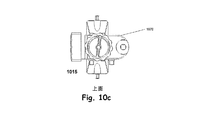
図10a〜10cは、それぞれ、本発明の他の典型的な実施形態による複合可動継ぎ手の正面画像1005、側面画像1010、及び上面画像1015である。図11は、図11a〜10cに図示した本発明の他の典型的な実施形態による複合可動継ぎ手の等角投影画像1100である。図10a、10b、10c、及び11を参照すると、この実施形態では、複合可動継ぎ手1005、1010、1015、1020、1100が2つの回転関節1070、1080及びクランプアセンブリ1060から構成されている。第1の回転関節は、本明細書ではロールジョイント1070とも呼ばれ、支柱構造部840(図8)の主軸に直交する軸回りにプラスマイナス90度の範囲内の回転運動をもたらす。第2の回転関節は、本明細書ではピッチジョイント1080とも呼ばれ、ロールジョイント1070の出力部に直接固定されており、このために、ロールジョイント1070の回転運動に追従する。ピッチジョイント1080は、ロールジョイント1070の出力軸に対して直交する軸の回りにプラスマイナス60度の範囲内の回転運動をもたらす。ピッチジョイント1080及びロールジョイント1070は、ロールピン1050を利用して、互いに固定されている。クランプアセンブリ1060が、ピッチジョイント1080の出力部にウッドラフキー(半月キー)を利用して取り付けられている。ウッドラフキーは、クランプアセンブリーの断面図、図15e、に詳細に示されている。
FIGS. 10 a-10 c are a
図12aは、本発明の他の典型的な実施形態による複合可動継ぎ手の2つの回転関節1210のうちの一方であるロールジョイントの正面画像である。図12b〜12dは、同じ回転関節の側面画像1220、上面画像1230、及び等角投影画像1240である。図12eは、図12cの複合可動継ぎ手の2つの回転関節のうちの一方の断面A−Aの画像1250である。図12fは、図12bの複合可動継ぎ手の2つの回転関節のうちの一方の断面B−Bの画像1270である。図12gは、図12bの複合可動継ぎ手の2つの回転関節のうちの一方の断面C−Cの画像1280である。図12hは、図12bの複合可動継ぎ手の2つの回転関節のうちの一方の断面D−Dの画像1290である。図12aから12hまでを参照すると、断面A−Aは、ハウジング1257の図を表しており、このハウジング1257は、ロールジョイント1210、1220、1230、1240の構造上の支持部となっており、ロールジョイント1210、1220、1230、1240の全ての内部部品を収容している。ねじ1256は、ロールジョイント1210、1220、1230、1240がはめられている支柱840(図8a)に締め付け荷重を加えており、ロールジョイント1210、1220、1230、1240の支柱840(図8a)に対する位置を固定するのに用いられている。残りの機構は、ロールジョイント1210、1220、1230、1240を微調整するのに利用される。
FIG. 12a is a front image of a roll joint that is one of two
滑り軸受け1259が駆動軸1258をハウジング1257の中で支持している。駆動軸1258に連結されているのは、オルダム板1255である。オルダム板1255は、その板の平面から突出している細長い突出部、及び駆動軸1258のスロットを利用して駆動軸1258にスライド可能に係合している。オルダム板1255の反対側に連結されているのは、歯車1253である。この歯車1253は、駆動軸1258と同様に、スロットを有しており、このスロットはオルダム板1255の平面から突出している細長い突出部と係合している。この機構は、歯車1253及び駆動軸1258の間のトルクを、径方向の位置合わせ不良を許容しながら、効率よく伝達する。歯車1253の径方向の位置合わせは、カム1251により調整される。カム1251は、断面が円形であり、回転軸から偏心した軸を有している。この回転軸は、円形突出部によって規定されており、この円形突出部は、つまみ式の調整部1254の内側にある。つまみ式調整部1254は、カム1251のツリーパン(tree pan)と干渉している。円形突出部自体、つまみ式調整部34のツリーパンに対し偏心している。このつまみ式調整部34のツリーパンは、つまみ式調整部1254の回転軸をハウジング1257に対して調整している。カム1251は、固定用ノブ1252に固定されており、この固定用ノブ1252を回すと、カム1251が回転する。カム1251の外径部がカム1251のツリーパンに対して偏心している度合いは、つまみ式調整部1254の内側突出部がつまみ式調整部1254のツリーパンに対して偏心している度合いに等しい。このようにカム1251の偏心が一致しているので、つまみ式調整部1254の偏心を打ち消して歯車1253をハウジング1257と同心にしたり、カム1251のハウジング1257に対する偏心の度合いを2倍にして歯車1253をハウジング1257と接触させることができる。
A sliding bearing 1259 supports the
ハウジング1257は内歯を有し、この内歯は歯車1253の外歯と等しいピッチを有するが、ハウジング1257の歯数は、ハウジング1257の全歯数の極く一部の分だけ歯車1253の歯数を超過している。この小さな歯数の差は、2つのことを果たす。第1に、この差は、歯車の歯が接触している側で噛み合い、隙間のある側で外れるような隙間を可能にしている。第2に、歯数の差でハウジング1257の総歯数を割ったものが歯車減速比である。この種の歯車減速は、サイクロイド減速として公知である。
The
図12fは、歯車のかみ合いの断面B−Bを示しており、偏心の度合いを示している。同様に、同種の減速は、ハーモニックドライブと呼ばれる装置を用いて実現できる。ハーモニックドライブでは、内側の歯車が柔軟な部材であり、この柔軟な部材は、楕円形の軸受けを用いて、又は楕円の2つの焦点に中心が配置されている2つの軸受けを用いて楕円形に変形されている。この内側の歯車は、楕円の主軸上で歯が噛み合っており、楕円の短軸上で隙間を有している。 FIG. 12f shows a cross section BB of the meshing of the gears and shows the degree of eccentricity. Similarly, the same kind of deceleration can be realized by using a device called a harmonic drive. In a harmonic drive, the inner gear is a flexible member that can be elliptical using an elliptical bearing or using two bearings centered at the two focal points of the ellipse. It has been transformed. The inner gear has teeth meshing on the major axis of the ellipse and has a gap on the minor axis of the ellipse.
ノブ式調整部1254の回り止めを行うのに、ボール押さえ(ball detent)が使用されている。図12gには、断面C−Cが描かれている。つまみ式調整部1254は、ボール押さえがある領域において、ツリーパンの内径じゅうにギザギザを有している。このギザギザは、鋼球1261と係合する。鋼球1261は、エラストマー(ゴム)ボール1260を圧縮することによって外方へばね荷重をかけられている。鋼球1261及びエラストマーボール1260は、共に、径方向に延びる平底穴の中に配置されている。つまみ式調整部1254を回転させることにより、エラストマーボール1260が押しつぶされ、鋼球1261がつまみ式調整部1254のギザギザから外れる。
A ball detent is used to prevent the
断面D−Dを描いている図12hを参照すると、つまみ式調整部1254が正方形断面のワイヤ1262を用いてハウジング1257に固定されている。ワイヤ1262は、つまみ式調整部1254の孔に通されて挿入されている。つまみ式調整部1254の穴は、ツリーパンの内側の接線となっている。ワイヤ1262は、つまみ式調整部1254のツリーパンの壁部にある溝に沿うとともに、ハウジング1257の壁部にある溝に沿っている。当業者には、つまみ式調整部1254をハウジング1257に固定するのに、他の方法、例えば止め輪又はスウェージング法を用いることもできることが分かるであろう。
Referring to FIG. 12 h depicting a section DD, a knob-
図12aから12hまでに関連して上述したロールジョイント1210、1220、1230、1240の機械的な動作は、図8a、8b、及び8cに図示したようにこの別の実施形態を含む他の3つの回転関節と同じである。
The mechanical operation of the
図13は、本発明の典型的な実施形態による可動継ぎ手構造の2つの回転関節のうちの第1の方の駆動機構の斜視図である。つまみ式調整部1310が、オルダム板1320を介して駆動軸1330に連結されている。オルダム板1320は、オルダム板の平面から突出している細長い突起部、及び駆動軸1330のスロットを利用して駆動軸1330にスライド可能に係合している。このような連結機構は、オルダム板1320の平面の両側から突出しており、互いに直交している細長い突起部によって実現されている。
FIG. 13 is a perspective view of a first drive mechanism of two rotary joints of a movable joint structure according to an exemplary embodiment of the present invention. A knob
図14aは、本発明の他の典型的な実施形態による複合可動継ぎ手の2つの回転関節のうちの第2の方、すなわちピッチジョイントの正面画像1410である。図14bは、本発明の他の典型的な実施形態による複合可動継ぎ手の2つの回転関節のうちの第2の方の側面画像1420である。図14cは、本発明の他の典型的な実施形態による複合可動継ぎ手の2つの回転関節のうちの第2の方の上面画像1430である。図14dは、本発明の他の典型的な実施形態による複合可動継ぎ手の2つの回転関節のうちの第2の方の等角投影画像1440である。図14eは、図14cに示した複合可動継ぎ手の2つの回転関節のうちの第2の方の断面A−Aの画像1450である。
FIG. 14a is a
図14aから14eまでを参照すると、断面A−Aは、ハウジング1455の図を表している。ハウジング1455は、ピッチジョイント1410、1420、1430、1440、1450の構造上の支持部となっており、ピッチジョイント1410、1420、1430、1440、1450の全ての内部部品を収容している。ねじ1460、1465は、2つの領域で締め付け荷重を加えている。第1のねじは、ロールジョイントの出力ボス(不図示)をクランプ締めして、ピッチジョイント1410、1420、1430、1440、1450のロールジョイント(不図示)に対する回転を防ぐ。このようなクランプ締め動作は、安全に固定することを意図しており、かつ、衝撃又は持ち上げ荷重(heaving load)を受けて歯車減速機構が逆動することによってピッチジョイント1410、1420、1430、1440、1450が決して動かないようにすることを意図したものである。第2の締めねじは、ピッチジョイント1410、1420、1430、1440、1450の駆動軸1470をピッチジョイント1410、1420、1430、1440、1450のハウジング1455にクランプ締めする。このクランプ締め動作は、第1のねじクランプ締め動作と同じ理由で行うものであり、具体的には、クランプアセンブリのピッチジョイント1410、1420、1430、1440、1450に対する回転を防止する。駆動軸1470は、ハウジング1455の中に2つのすべり軸受け1475、1480を用いて支持されている。ピッチジョイント1410、1420、1430、1440、1450の他の全ての特徴は、図12aから12hまでとの関連でロールジョイントについて説明した特徴と同じである。
With reference to FIGS. 14 a-14 e, section AA represents a view of
図15aは、本発明の典型的な実施形態によるピンクラップユニットの正面画像1510である。図15bは、本発明の典型的な実施形態によるピンクラップユニットの側面画像1520である。図15cは、本発明の典型的な実施形態によるピンクラップユニットの上面画像1530である。図15dは、本発明の典型的な実施形態によるピンクラップユニットの等角投影画像1540である。図15eは、図15cのピンクラップユニットの断面A−Aの画像1550である。
FIG. 15a is a
図15aから15eまでを参照すると、ハウジング1555は、ピンクランプ1510、1520、1530、1540、1550の構造上の支持部となっており、駆動軸1470(図14e)にウッドラフキーを用いて連結されている。ウッドラフキーのためのスロット1585は、ハウジング1550の中にある。2つのクランプスレッド(clamp sleds)1570がハウジング1555に蟻継ぎ構造を用いて保持されている。クランプスレッド1570には、蟻継ぎ溝の端部に向けてばね1575を用いて予め荷重がかけられており、また、クランプスレッド1570が蟻継ぎ溝から滑り出すことが2つのロールピン1565で防止されている。一方が右巻きのねじ孔を有し、他方が左巻きのねじ孔を有する2つの支持部材(くさび形止め具、クリート)1580が蟻継ぎ溝の真下にある切削部に配置されている。各支持部材1580の上端は、切削部から飛び出て蟻継ぎ溝の中まで伸びている。ばね1575は、各クランプスレッド1570にある小さな円形のボスによって保持されている。円形のボスは、ばね1575の内径部にはまっている。ねじ付きロッド1560であって一方の端部に右巻きの雄ねじがあり、他方の端部に左巻きの雄ねじのあるものが、ハウジング1555の横孔の中に配置されており、支持部材1580にねじ込まれている。六角形又は四角形のヘッドがねじ付きロッド1560の各端部にあってもよい。ロッド1560を回転させると支持部材1580がロッドの中心に向けて移動するか、ロッドの端部に向けて異動する。このようにすると、支持部材1580が、外側に移動したときに、クランプスレッド1570と接触して、クランプスレッド1570とハウジング1555との間にピン(不図示)をクランプ締めする。支持部材1580がねじ付きロッド1560の中心の方へ移動すると、ばねがクランプ締めの力を供給する。ばね1575によりピン(不図示)が所定位置にカチッとはまることができる。これは、クランプスレッド1570及びハウジング1555がクランプ締めするくぼみへの導入部として面取りされた端部を有するからである。ばね1575は、骨固定器を位置決めして、支持部材1580が外側へと移動してピンをハウジング1555に確実にクランプ締めするようにねじ付きロッド1560を回転させている間、ピンを所定位置に保持する。当業者には、このクランプ構造が本発明の片側骨固定器で使用できる数多くの種類のクランプの候補の一例であることが分かるであろう。
Referring to FIGS. 15a to 15e, the
図16aは、本発明の他の典型的な実施形態による支柱構造部の正面の画像1610である。図16bは、本発明の他の典型的な実施形態による支柱構造部の側面の画像1620である。図16cは、本発明の他の典型的な実施形態による支柱構造部の上面の画像1630である。図16dは、本発明の他の典型的な実施形態による支柱構造部の等角投影画像1640である。図16aから16dを参照すると、支柱構造部1610、1620、1630、1640は、3つの部品から構成されており、メインボディ1650は、トップチューブ1660がはめ込まれており、このメインボディ1650に対するトップチューブ1660の長さ調整に備えている。トップチューブ1650には、ヨージョイント(yaw joint)1670がはめ込まれている。これは、メインボディ1650とトップチューブ1660とを組み合わせたものに対するヨージョイント1670の回転を可能にしている。
FIG. 16a is an
図17aは、本発明の他の典型的な実施形態によるベースチューブアセンブリの正面の画像1710である。図17bは、本発明の他の典型的な実施形態によるベースチューブアセンブリの側面の画像1720である。図17cは、本発明の他の典型的な実施形態によるベースチューブアセンブリの底面の画像1730である。図17dは、本発明の他の典型的な実施形態によるベースチューブアセンブリの等角投影画像1740である。図17eは、図17cのベースチューブアセンブリの断面A−Aの画像1750である。
FIG. 17a is an
図17aから17eまでを参照すると、スクリューアジャスター1790が、支柱のハウジング1760内に止め輪1780を用いて保持されている。O−リング1770が、支柱のハウジング1760の内径部に沿った周溝にはめ込まれており、スクリューアジャスター1790の外径部を押しつぶして摩擦を発生させ、スクリューアジャスター1790が、衝撃や振動を受けて、後方に動いたり、回転したりすることを防止している。
Referring to FIGS. 17 a-17 e, a
図18aは、本発明の他の典型的な実施形態によるトップチューブアセンブリの正面の画像1810である。図18bは、本発明の他の典型的な実施形態によるトップチューブアセンブリの側面の画像1820である。図18cは、本発明の他の典型的な実施形態によるトップチューブアセンブリの上面の画像1830である。図18dは、本発明の他の典型的な実施形態によるトップチューブアセンブリの等角投影画像1840である。
FIG. 18a is an
図18aから18dを参照すると、トップチューブハウジング1850が、トップチューブ1810、1820、1830、1840の構造上の主支持部となっている。トップチューブ1810、1820、1830、1840に取り付けられているのは、ガイドレール1890である。ガイドレール1890は、伸ばした量を読みとるための目盛りを付けたスケールを有している。ガイドレール1890は、さらに、トップチューブ1810、1820、1830、1840がトップチューブハウジング1850に対して回転するのを防止する役割を果たしている。ガイドレール1890は、トップチューブハウジング1850の蟻継ぎ溝にスライドして入っている。ガイドレール1890自体、断面が蟻継ぎ形状をしている。また、ガイドレール1890は、固定用のロールピン1880を有している。トップチューブハウジング1850の先端には、中ぐり穴1845がある。この中ぐり穴1845には、ヨージョイント(不図示)が入る。中ぐり穴1845の中には、ヨージョイント(不図示)の駆動軸を回転に関してトップチューブハウジング1850に固定するようにキー溝1895がある。ヨージョイント(不図示)をロックするには、締め付けねじ1870を2つのクランプブッシング1860とともに使用する。2つのクランプブッシング1860の一方はねじが切ってあり、他方にはクリアランスホールがある。締め付けねじ1870を締めると、トップチューブハウジング1850の回転がロックされる。
Referring to FIGS. 18a to 18d, the
図19aは、本発明の他の典型的な実施形態による図16の支柱構造部のヨージョイントの正面の画像1910である。図19bは、本発明の他の典型的な実施形態による図16の支柱構造部のヨージョイントの側面の画像1920である。図19cは、本発明の他の典型的な実施形態による図16の支柱構造部のヨージョイントの底面の画像1930である。図19dは、本発明の他の典型的な実施形態による図16の支柱構造部のヨージョイントの等角投影画像1940である。図19eは、図19cに示した図16の支柱構造部のヨージョイントの断面A−Aの画像1950である。
19a is an
図18d及び19aから19eまでを参照すると、ウッドラフキー1960がトップチューブハウジング1850のスロットに係合している。駆動軸1970は、トップチューブ1840の先端部にある中ぐり穴1845の中に支持されている。ヨージョイントハウジング1965は、構造上の主支持部となっており、ヨージョイント1910、1920、1930、1940、1950の全ての部品を収容している。また、ヨージョイントハウジング1965は、上部可動継ぎ手(不図示)、ヨージョイントハウジング1965の外径部周りの取付箇所を提供する。ヨージョイントの動作及び機構の説明は、図12aから12hに関連して前述したロールジョイントと同一である。
Referring to FIGS. 18 d and 19 a-19 e, a woodruff key 1960 engages a slot in the
当業者には、典型的な片側骨固定器の部品を耐食鋼(CRES、又はステンレス鋼)、アルミニウム合金、真鍮、又は医療機器に一般的に使用される他の材料から製作することができることが分かるであろう。 One skilled in the art could make typical unilateral bone anchor components from corrosion resistant steel (CRES, or stainless steel), aluminum alloys, brass, or other materials commonly used in medical devices. You will understand.
当業者には、本発明が、6自由度での奇形の大ざっぱな操作と微調整とを可能にする片側外付け骨固定器をサポートしていることが分かるであろう。この装置は、支柱アセンブリと、この支柱アセンブリの各端部に1つずつある2つの複合可動継ぎ手を備えていてもよい。複合可動継ぎ手の一方は、それぞれが歯車減速機構を含む2つの回転関節を備え、支柱回りに回転することができてもよい。第2の複合可動継ぎ手は、それぞれが歯車減速機構を含む2つの回転関節を含み、支柱アセンブリの長さに沿って移動することができてもよい。歯車減速機構は、骨固定器の粗調整及び微調整を可能にするヘリカルスプラインアセンブリを含んでいてもよい。 One skilled in the art will appreciate that the present invention supports a unilateral external bone anchor that allows for rough manipulation and fine tuning of the deformity in six degrees of freedom. The device may comprise a strut assembly and two compound movable joints, one at each end of the strut assembly. One of the compound movable joints may be provided with two rotary joints each including a gear reduction mechanism, and may be able to rotate around the column. The second compound movable joint may include two rotating joints, each including a gear reduction mechanism, and may be movable along the length of the strut assembly. The gear reduction mechanism may include a helical spline assembly that allows coarse and fine adjustment of the bone anchor.
Claims (23)
第1及び第2の端部、及び縦方向の支柱軸を有し、前記支柱軸に沿って伸縮自在に調整可能な支柱と、
前記支柱の第1の端部、及び第1の骨取付装置に連結される第1の複合可動継手であって、第1の歯車機構を含み、前記第1の歯車機構は、前記第1の骨取付装置が第1の骨部分に係合されている間、互いに及び前記支柱軸に概ね直角な第1及び第2の軸に対する前記第1の骨取付装置の直線運動及び回転運動を制御するように作動可能である、第1の複合可動継手と、
前記支柱の第2の端部、及び第2の骨取付装置に連結される第2の複合可動継手であって、第2の歯車機構を含み、前記第2の歯車機構は、前記第2の骨取付装置が第2の骨部分に係合されている間、前記第2の骨取付装置の直線的な調整及び回転の調整を制御するように作動可能である、第2の複合可動継手と、
を備え、
前記第1の複合可動継手は、前記支柱軸に関して回転可能である、固定器。 A unilateral fixator for adjustment of the first bone part relative to the second bone part,
A column having first and second end portions and a column column in the vertical direction, and a column that can be freely extended and contracted along the column axis;
A first composite movable joint coupled to a first end portion of the column and a first bone attachment device, the first movable joint including a first gear mechanism, wherein the first gear mechanism includes the first gear mechanism. Controls linear and rotational movement of the first bone attachment device relative to each other and to first and second axes generally perpendicular to the strut axis while the bone attachment device is engaged with the first bone portion. A first composite movable joint that is operable to:
A second composite movable joint coupled to a second end of the column and a second bone attachment device, the second movable joint including a second gear mechanism, wherein the second gear mechanism includes the second gear mechanism; A second composite movable joint operable to control linear and rotational adjustments of the second bone attachment device while the bone attachment device is engaged with the second bone portion; ,
With
The first composite movable joint is a fixator that is rotatable with respect to the support shaft.
縦方向の支柱軸、及び第1及び第2の端部を有し、且つ前記支柱軸に沿って調整可能な長さを有する支柱と、
前記支柱軸に対して概ね直角な第1の回転軸を定める第1の回転関節であって、前記支柱の第1の端部に連結された第1の回転関節と、
前記第1の回転軸及び前記支柱軸に対して概ね直角な第2の回転軸を定める第2の回転関節であって、前記第1の回転関節、及び第1の骨取付装置に連結された第2の回転関節と、
前記支柱の第2の端部に連結され、且つ前記第1の回転軸と概ね平行な第3の回転軸を定める第3の回転関節と、
前記第3の回転関節、及び第2の骨取付装置に連結された第4の回転関節であって、前記第2の回転軸と概ね平行な第4の回転軸を定める第4の回転関節と、
を備え、
前記第1、第2、第3、及び第4の回転関節の各々は、前記第1及び第2の骨取付装置が前記第1及び第2の骨部分に係合されている間、それぞれの第1、第2、第3、及び第4の回転軸に関する回転運動及び直線運動を調整するように作動可能な対応する歯車機構を含む、固定器。 A unilateral fixator for adjustment of the first bone part relative to the second bone part,
A strut having a longitudinal strut axis and first and second ends and having a length adjustable along the strut axis;
A first rotational joint defining a first rotational axis generally perpendicular to the strut axis, wherein the first rotational joint is coupled to a first end of the strut;
A second rotary joint defining a second rotary axis generally perpendicular to the first rotary axis and the strut axis, wherein the second rotary joint is connected to the first rotary joint and the first bone attachment device A second rotational joint;
A third rotational joint coupled to the second end of the support and defining a third rotational axis generally parallel to the first rotational axis;
A fourth rotary joint coupled to the third rotary joint and a second bone attachment device, wherein the fourth rotary joint defines a fourth rotary axis generally parallel to the second rotary axis; ,
With
Each of the first, second, third, and fourth rotational joints is disposed while the first and second bone attachment devices are engaged with the first and second bone portions, respectively. A fixture including a corresponding gear mechanism operable to coordinate rotational and linear motion about the first, second, third, and fourth rotational axes.
縦方向の支柱軸、及び第1及び第2の端部を有し、且つ前記支柱軸に沿って調整可能な長さを有する支柱と、
前記支柱の第1の端部に連結された第1の複合可動継手であって、前記第1の骨部分に係合可能な第1のクランプに連結され、且つ互いに及び前記支柱軸に対して概ね直角な第1及び第2の軸に関する回転及び平行移動を制御するように作動可能な第1の歯車機構を含む、前記第1の複合可動継手と、
前記支柱の第2の端部に連結された第2の複合可動継手であって、前記第2の骨部分に係合可能な第2のクランプに連結され、それぞれ前記第1及び第2の軸と概ね平行な第3及び第4の軸に関する回転及び平行移動を制御するように作動可能な第2歯車機構を含む第2の複合可動継手と、
を備え、
前記第1の複合可動継手は、前記支柱軸に関して回転可能であり、且つ、前記第2の複合可動継手は前記支柱軸に対してスライド可能である、固定器。 A unilateral fixator for adjustment of the first bone part relative to the second bone part,
A strut having a longitudinal strut axis and first and second ends and having a length adjustable along the strut axis;
A first composite movable joint coupled to a first end of the column, coupled to a first clamp engageable with the first bone portion, and to each other and to the column axis The first composite movable joint including a first gear mechanism operable to control rotation and translation about first and second axes that are generally perpendicular;
A second composite movable joint coupled to the second end of the column, the second movable joint being coupled to a second clamp engageable with the second bone portion, the first and second shafts, respectively; A second composite movable joint including a second gear mechanism operable to control rotation and translation about third and fourth axes generally parallel to;
With
The first compound movable joint is rotatable with respect to the column axis, and the second compound movable joint is slidable with respect to the column axis.
Applications Claiming Priority (4)
| Application Number | Priority Date | Filing Date | Title |
|---|---|---|---|
| US41129102P | 2002-09-17 | 2002-09-17 | |
| US60/411,291 | 2002-09-17 | ||
| US42643902P | 2002-11-14 | 2002-11-14 | |
| US60/426,439 | 2002-11-14 |
Related Parent Applications (1)
| Application Number | Title | Priority Date | Filing Date |
|---|---|---|---|
| JP2004538201A Division JP4490821B2 (en) | 2002-09-17 | 2003-09-17 | Unilateral bone anchor |
Publications (2)
| Publication Number | Publication Date |
|---|---|
| JP2010142647A JP2010142647A (en) | 2010-07-01 |
| JP4945791B2 true JP4945791B2 (en) | 2012-06-06 |
Family
ID=32033538
Family Applications (2)
| Application Number | Title | Priority Date | Filing Date |
|---|---|---|---|
| JP2004538201A Expired - Fee Related JP4490821B2 (en) | 2002-09-17 | 2003-09-17 | Unilateral bone anchor |
| JP2009291283A Expired - Fee Related JP4945791B2 (en) | 2002-09-17 | 2009-12-22 | Unilateral bone anchor |
Family Applications Before (1)
| Application Number | Title | Priority Date | Filing Date |
|---|---|---|---|
| JP2004538201A Expired - Fee Related JP4490821B2 (en) | 2002-09-17 | 2003-09-17 | Unilateral bone anchor |
Country Status (6)
| Country | Link |
|---|---|
| US (2) | US7282052B2 (en) |
| EP (1) | EP1549235A4 (en) |
| JP (2) | JP4490821B2 (en) |
| AU (1) | AU2003272557B2 (en) |
| CA (1) | CA2499373A1 (en) |
| WO (1) | WO2004026103A2 (en) |
Families Citing this family (96)
| Publication number | Priority date | Publication date | Assignee | Title |
|---|---|---|---|---|
| GB0107708D0 (en) * | 2001-03-28 | 2001-05-16 | Imp College Innovations Ltd | Bone fixated,articulated joint load control device |
| AU2003297280B2 (en) * | 2002-11-14 | 2010-04-08 | Extraortho, Inc | Method for using a fixator device |
| US7608074B2 (en) | 2003-01-10 | 2009-10-27 | Smith & Nephew, Inc. | External fixation apparatus and method |
| US8353933B2 (en) * | 2007-04-17 | 2013-01-15 | Gmedelaware 2 Llc | Facet joint replacement |
| EP1690506B1 (en) * | 2005-02-09 | 2008-08-20 | Stryker Trauma SA | External fixation device; in particular for increasing a distance between clamping elements |
| US8055487B2 (en) * | 2005-02-22 | 2011-11-08 | Smith & Nephew, Inc. | Interactive orthopaedic biomechanics system |
| US8603017B2 (en) | 2005-03-07 | 2013-12-10 | American Medical Innovations, L.L.C. | Vibrational therapy assembly for treating and preventing the onset of deep venous thrombosis |
| US7588571B2 (en) | 2005-03-18 | 2009-09-15 | Ron Anthon Olsen | Adjustable splint for osteosynthesis with modular joint |
| US20060229605A1 (en) * | 2005-03-18 | 2006-10-12 | Olsen Ron A | Adjustable splint for osteosynthesis with incrementing assembly for adjustment in predetermined increments |
| US7722609B2 (en) * | 2005-04-25 | 2010-05-25 | Synthes Usa, Llc | Outrigger with locking mechanism |
| US8758343B2 (en) | 2005-04-27 | 2014-06-24 | DePuy Synthes Products, LLC | Bone fixation apparatus |
| US20070055233A1 (en) * | 2005-08-03 | 2007-03-08 | Brinker Mark R | Apparatus and method for repositioning fractured bone fragments using an arc shaped panel and half pins |
| WO2007103413A2 (en) * | 2006-03-08 | 2007-09-13 | Juvent, Inc. | System and method for providing therapeutic treatment using a combination of ultrasound and vibrational stimulation |
| US8702705B2 (en) * | 2006-03-23 | 2014-04-22 | Bruce H. Ziran | Electromechanically driven external fixator and methods of use |
| WO2008008340A2 (en) * | 2006-07-11 | 2008-01-17 | Juvent, Inc. | System and method for a low profile vibrating plate |
| US20080139977A1 (en) * | 2006-12-07 | 2008-06-12 | Juvent. Inc. | Non-invasive methods for vibrational treatment of bone tissue following a bone-related medical procedure |
| GB2444907A (en) * | 2006-12-20 | 2008-06-25 | Promedics Ltd | A joint fixator |
| US8506566B2 (en) * | 2007-07-30 | 2013-08-13 | John Peter Karidis | Adjustable length strut apparatus for orthopaedic applications |
| US20090093820A1 (en) * | 2007-10-09 | 2009-04-09 | Warsaw Orthopedic, Inc. | Adjustable spinal stabilization systems |
| US8114077B2 (en) * | 2008-02-01 | 2012-02-14 | Stryker Trauma Sa | Clamping pin |
| EP2085038B1 (en) * | 2008-02-01 | 2011-11-30 | Stryker Trauma SA | Ball joint for an external fixator |
| EP2085037B1 (en) * | 2008-02-01 | 2013-07-24 | Stryker Trauma SA | Telescopic strut for an external fixator |
| EP2240084B1 (en) | 2008-02-05 | 2016-05-11 | Texas Scottish Rite Hospital For Children | External fixator ring |
| WO2009100459A1 (en) | 2008-02-08 | 2009-08-13 | Texas Scottish Rite Hospital For Children | External fixation strut |
| EP3245966B1 (en) | 2008-02-12 | 2020-06-17 | Texas Scottish Rite Hospital For Children | Connecting rod for an external fixation device |
| JP5529047B2 (en) * | 2008-02-18 | 2014-06-25 | テキサス スコティッシュ ライト ホスピタル フォー チルドレン | Tool and method for external fixed support adjustment |
| WO2010104567A1 (en) * | 2009-03-10 | 2010-09-16 | Stryker Trauma Sa | External fixation system |
| DE202010018413U1 (en) * | 2009-03-30 | 2016-06-09 | Tq-Systems Gmbh | Transmission, engine-transmission unit, vehicle and generator with a gearbox |
| US11280394B2 (en) * | 2009-03-30 | 2022-03-22 | Tq-Systems Gmbh | Gear, motor-gear unit, vehicle, generator with a gear, and force transmitting element |
| MY174417A (en) * | 2009-06-12 | 2020-04-17 | Univ Malaya | An improved bone holding device for limb support frame |
| EP2294994B1 (en) * | 2009-09-11 | 2018-04-04 | Stryker European Holdings I, LLC | External fixation component |
| USD633208S1 (en) | 2009-09-11 | 2011-02-22 | Stryker Trauma Ag | External fixation clamp |
| US8858555B2 (en) | 2009-10-05 | 2014-10-14 | Stryker Trauma Sa | Dynamic external fixator and methods for use |
| CN102858262B (en) * | 2009-12-01 | 2015-05-13 | 新特斯有限责任公司 | Non-fusion scoliosis expandable spinal rod |
| US8257353B2 (en) | 2010-02-24 | 2012-09-04 | Wright Medical Technology, Inc. | Orthopedic external fixation device |
| ES2446370T3 (en) | 2010-08-11 | 2014-03-07 | Stryker Trauma Sa | External fixing system |
| US8945128B2 (en) | 2010-08-11 | 2015-02-03 | Stryker Trauma Sa | External fixator system |
| US11141196B2 (en) | 2010-08-11 | 2021-10-12 | Stryker European Operations Holdings Llc | External fixator system |
| CA2809002C (en) | 2010-08-20 | 2017-11-21 | Amei Technologies, Inc. | Method and system for roentgenography-based modeling |
| ES2541831T3 (en) | 2010-10-07 | 2015-07-27 | Stryker Trauma Sa | Coupling element for an external fixing device |
| US9474551B2 (en) | 2010-10-09 | 2016-10-25 | Universidad Del Valle | External fixation device adaptable for bone fractures |
| US8246658B2 (en) * | 2010-10-29 | 2012-08-21 | Warsaw Orthopedic, Inc. | Spinal connector assembly |
| AU2011331999B2 (en) | 2010-11-22 | 2016-07-21 | Synthes Gmbh | Non-fusion scoliosis expandable spinal rod |
| US8585703B2 (en) * | 2010-12-09 | 2013-11-19 | Stryker Trauma Sa | Adjustment tool for external fixator |
| ES2541207T3 (en) | 2010-12-14 | 2015-07-16 | Stryker Trauma Sa | Fixing clamp with selector wheel |
| ES2540276T3 (en) | 2010-12-14 | 2015-07-09 | Stryker Trauma Sa | Fixing clamp |
| USD683461S1 (en) | 2010-12-14 | 2013-05-28 | Stryker Trauma Sa | Hinge coupling |
| USD704840S1 (en) | 2010-12-14 | 2014-05-13 | Stryker Trauma Sa | Hinge coupling |
| ES2540256T3 (en) | 2010-12-14 | 2015-07-09 | Stryker Trauma Sa | Fixing clamp |
| USD720853S1 (en) | 2010-12-14 | 2015-01-06 | Stryker Trauma Sa | Fixation clamp |
| USD682426S1 (en) | 2011-06-14 | 2013-05-14 | Stryker Trauma Sa | Fixation clamp |
| USD663030S1 (en) | 2011-06-14 | 2012-07-03 | Styker Trauma SA | Fixation clamp |
| CN102283732A (en) * | 2011-06-24 | 2011-12-21 | 毕宏政 | Self-locking fracture reduction fixing apparatus |
| US9101398B2 (en) | 2012-08-23 | 2015-08-11 | Stryker Trauma Sa | Bone transport external fixation frame |
| US9301782B2 (en) * | 2012-09-04 | 2016-04-05 | Zimmer, Inc. | External fixation |
| US9924969B2 (en) * | 2012-09-04 | 2018-03-27 | Zimmer, Inc. | External fixation |
| US8574232B1 (en) * | 2012-11-13 | 2013-11-05 | Texas Scottish Hospital for Children | External fixation connection rod for rapid and gradual adjustment |
| ITVR20130013A1 (en) * | 2013-01-21 | 2014-07-22 | Tecres Spa | EXTERNAL FIXING DEVICE FOR THE TREATMENT OF BONE FRACTURES |
| US10993868B2 (en) * | 2013-03-14 | 2021-05-04 | Mdpo Llc | Dynamic foot plate |
| US10980655B1 (en) | 2013-03-14 | 2021-04-20 | Mdpo Llc | Dynamic foot plate |
| WO2014147583A1 (en) | 2013-03-20 | 2014-09-25 | Tq-Systems Gmbh | Harmonic pin ring gearing |
| CN103126755A (en) * | 2013-03-26 | 2013-06-05 | 江苏荷普医疗器械有限公司 | Multifunctional self-locking type orthopedic outer fixing frame |
| US9962188B2 (en) | 2013-10-29 | 2018-05-08 | Cardinal Health 247. Inc. | External fixation system and methods of use |
| US9872706B1 (en) * | 2014-05-14 | 2018-01-23 | Devise Ortho Inc. | External fixation device |
| WO2015183226A2 (en) * | 2014-05-27 | 2015-12-03 | Spi̇namer Sağlik Ürünleri̇ Sanayi̇ Ve Teknoloji̇ Li̇mi̇ted Şi̇rketi̇ | Unilateral bone fixator system enabling bone extension and three dimensional fixation |
| TR201406039A2 (en) | 2014-05-29 | 2015-12-21 | Spinamer Saglik Ueruenleri Sanayi Ve Teknoloji Ltd Sirketi | Monoaxial unilateral bone fixator system with position sensor and motor. |
| US10314618B2 (en) * | 2014-07-25 | 2019-06-11 | The General Hospital Corporation | System and method for an external hip fixator |
| CN106794034B (en) * | 2014-08-11 | 2019-08-16 | 捷迈有限公司 | External fixation |
| US9962187B2 (en) * | 2014-08-11 | 2018-05-08 | Zimmer, Inc. | External fixation |
| EP3273885B1 (en) * | 2015-03-25 | 2024-05-22 | Zimmer, Inc. | External fixation |
| EP3310280B1 (en) | 2015-06-17 | 2024-10-23 | Zimmer, Inc. | Ankle fixation system |
| CN104983455B (en) * | 2015-07-17 | 2017-10-27 | 刘礼初 | Universal adjustment structure and distraction osteogenesis fixing device |
| US11259844B2 (en) * | 2015-10-05 | 2022-03-01 | Globus Medical Inc. | Growing rod for treating spinal deformities and method for using same |
| US11071568B2 (en) * | 2015-10-05 | 2021-07-27 | Globus Medical, Inc. | Growing rod for treating spinal deformities and method for using same |
| US10010350B2 (en) | 2016-06-14 | 2018-07-03 | Stryker European Holdings I, Llc | Gear mechanisms for fixation frame struts |
| DE102016122845A1 (en) | 2016-11-28 | 2018-05-30 | Tq-Systems Gmbh | Harmonic pinion gear, torque measuring device and freewheel assembly |
| US10874433B2 (en) | 2017-01-30 | 2020-12-29 | Stryker European Holdings I, Llc | Strut attachments for external fixation frame |
| RU2657937C1 (en) * | 2017-04-07 | 2018-06-18 | Федеральное государственное бюджетное образовательное учреждение высшего образования "Владимирский Государственный Университет имени Александра Григорьевича и Николая Григорьевича Столетовых" (ВлГУ) | Automated orthopedic external fixator |
| WO2019074722A2 (en) | 2017-10-10 | 2019-04-18 | Miki Roberto Augusto | Universal orthopedic clamp |
| WO2019229574A1 (en) | 2018-05-31 | 2019-12-05 | Tq-Systems Gmbh | Traction means with inner toothing and outer toothing, and transmission comprising traction means |
| CN109276300B (en) * | 2018-08-09 | 2020-12-18 | 盐城日升月恒智能科技有限公司 | Intramedullary and extramedullary combined bevel gear bone lengthening device |
| CN109259836B (en) * | 2018-08-09 | 2020-12-18 | 盐城日升月恒智能科技有限公司 | Intramedullary and extramedullary combined belt pulley bone lengthening device |
| CN109276301B (en) * | 2018-08-09 | 2020-12-18 | 盐城日升月恒智能科技有限公司 | Intramedullary and extramedullary combined electric bone lengthening device |
| CN109276299B (en) * | 2018-08-09 | 2020-12-18 | 盐城日升月恒智能科技有限公司 | Belt pulley bone extension fixture |
| BR112021003874A2 (en) | 2018-08-29 | 2021-05-18 | Amdt Holdings, Inc. | adjustable support sets for external fastening systems |
| CN112888387B (en) * | 2018-10-30 | 2024-08-20 | 史密夫和内修有限公司 | External fixing support |
| US11653951B2 (en) * | 2018-11-06 | 2023-05-23 | Ali Moradi | External orthopedic fixation device |
| CN109793562B (en) * | 2019-01-23 | 2020-06-16 | 胡将碟 | Dismantle convenient fracture fixation support frame |
| RU193832U1 (en) * | 2019-05-13 | 2019-11-18 | Общество С Ограниченной Ответственностью "Орто-Сув" | TELESCOPIC STAND FOR THE APPARATUS OF TRANSSTANCE OSTEOSYNTHESIS |
| IT201900007314A1 (en) | 2019-05-27 | 2020-11-27 | Orthofix Srl | Quick-connect clamp for external fixation systems |
| RU2744655C1 (en) * | 2020-02-10 | 2021-03-12 | Общество С Ограниченной Ответственностью "Орто-Сув" | Transosseous apparatus, telescopic stand for transosseous apparatus, computer system and method for modeling bone fragment displacement using transosseous apparatus |
| US11826077B2 (en) | 2020-03-23 | 2023-11-28 | Texas Scottish Rite Hospital For Children | External fixation strut |
| CN112773504B (en) * | 2020-12-31 | 2022-03-01 | 苏州迪凯尔医疗科技有限公司 | Adjustable connecting rod and navigation system auxiliary positioning device |
| WO2022168057A1 (en) | 2021-02-08 | 2022-08-11 | Nelson Saldanha Kiran Antony | System and devices for closed fracture reduction, deformity correction and fixation of bone |
| EP4415638A4 (en) * | 2021-10-18 | 2025-06-11 | A-Fix Inc. | Bone fixator with removable portion |
| US12433641B2 (en) | 2023-09-20 | 2025-10-07 | Şehmuz Işin | Unilateral external fixator apparatus and control method |
Family Cites Families (81)
| Publication number | Priority date | Publication date | Assignee | Title |
|---|---|---|---|---|
| US2250417A (en) | 1939-12-02 | 1941-07-22 | Zimmer Mfg Company | Fracture reduction and retention device |
| CH536107A (en) * | 1971-03-16 | 1973-04-30 | Paolo Prof Dr Med Riniker | Fixator for diaphyseal hernias |
| FR2464700A1 (en) * | 1979-09-14 | 1981-03-20 | Gourlandt Albert | METHOD AND APPARATUS FOR AUTOMATIC CLEARING OF VOLATILES, PREFERABLY OF CHILDREN, DIN-DUNNERS, PINTADEAUX |
| US4308863A (en) * | 1979-10-18 | 1982-01-05 | Ace Orthopedic Manufacturing, Inc. | External fixation device |
| US4502473A (en) * | 1981-08-06 | 1985-03-05 | National Research Development Corp. | Apparatus for external fixation of bone fractures |
| NO149831C (en) | 1981-11-27 | 1984-07-04 | Per Helland | EXTERNAL CORRECTION AND FIXING EQUIPMENT OF THE KNOCKS |
| US4483334A (en) * | 1983-04-11 | 1984-11-20 | Murray William M | External fixation device |
| US4628919A (en) * | 1983-09-09 | 1986-12-16 | Clyburn Terry | Dynamic external fixator and method of use |
| US4895141A (en) * | 1984-04-26 | 1990-01-23 | Harrington Arthritis Research Center | Unilateral external fixation device |
| IT1181490B (en) * | 1984-12-18 | 1987-09-30 | Orthofix Srl | ORTHOPEDIC APPARATUS FOR EXTERNAL AXIAL FIXING, WITH A WIDE RANGE OF ADAPTABILITY |
| US4730608A (en) * | 1986-03-05 | 1988-03-15 | Schlein Allen P | External bone-anchoring fixator |
| EP0314021A3 (en) | 1987-10-26 | 1989-12-06 | Howmedica GmbH | Fixing device for parts of bones |
| US4991579A (en) * | 1987-11-10 | 1991-02-12 | Allen George S | Method and apparatus for providing related images over time of a portion of the anatomy using fiducial implants |
| DE8807909U1 (en) * | 1988-06-18 | 1988-10-20 | Howmedica GmbH, 2314 Schönkirchen | Bone plate, especially small bone plate |
| CH678485A5 (en) * | 1988-12-15 | 1991-09-30 | Jaquet Orthopedie | |
| US5207676A (en) * | 1989-02-27 | 1993-05-04 | Jaquet Orthopedie S.A. | External fixator with controllable damping |
| CH679448A5 (en) * | 1989-02-27 | 1992-02-28 | Jaquet Orthopedie | |
| US4973331A (en) * | 1989-03-08 | 1990-11-27 | Autogenesis Corporation | Automatic compression-distraction-torsion method and apparatus |
| IT1234756B (en) * | 1989-03-17 | 1992-05-26 | Orthofix Srl | EXTERNAL FIXER PARTICULARLY SUITABLE TO BE APPLIED ON THE BASINS. |
| US4922896A (en) * | 1989-05-05 | 1990-05-08 | John M. Agee | Colles' fracture splint |
| US5454810A (en) * | 1990-02-05 | 1995-10-03 | Pohl; Anthony P. | External fixation device |
| US5074866A (en) * | 1990-10-16 | 1991-12-24 | Smith & Nephew Richards Inc. | Translation/rotation device for external bone fixation system |
| CH684928A5 (en) * | 1990-12-10 | 1995-02-15 | Jaquet Orthopedie | external fixator. |
| FR2683446A1 (en) * | 1991-11-08 | 1993-05-14 | Hardy Jean Marie | MODULAR EXTERNAL FIXER FOR IMMOBILIZING A FRACTURE FIREPLACE. |
| CA2093828A1 (en) * | 1992-04-16 | 1993-10-17 | Anthony Philip Pohl | External bone fixation device |
| US5603318A (en) * | 1992-04-21 | 1997-02-18 | University Of Utah Research Foundation | Apparatus and method for photogrammetric surgical localization |
| EP0599847B1 (en) * | 1992-06-25 | 1997-04-02 | Synthes AG, Chur | Osteosynthetic fixation device |
| WO1994010947A1 (en) * | 1992-11-10 | 1994-05-26 | Innovative Orthopaedics Manufacturing, Inc. | Dynamic external fixator for the wrist |
| US6162224A (en) * | 1995-02-15 | 2000-12-19 | Acumed, Inc. | External fixator for repairing fractures of distal radius and wrist |
| US5658283A (en) * | 1995-02-15 | 1997-08-19 | Huebner; Randall J. | External fixator for repairing fractures |
| US5545162A (en) * | 1995-02-15 | 1996-08-13 | Huebner; Randall J. | External fixator for repairing fractures of distal radius and wrist |
| US5976134A (en) * | 1995-06-01 | 1999-11-02 | Huebner; Randall J. | External fixator for repairing fractures |
| US6171309B1 (en) * | 1995-02-15 | 2001-01-09 | Acumed, Inc. | External fixator for repairing fractures of distal radius and wrist |
| GB2280608A (en) * | 1993-08-05 | 1995-02-08 | Hi Shear Fasteners Europ Ltd | External bone fixator |
| GB9325698D0 (en) * | 1993-12-15 | 1994-02-16 | Richardson James B | Patient-operated orthopedic device |
| ITVR940019A1 (en) * | 1994-03-07 | 1995-09-07 | Ortofix Srl | ORTHOPEDIC TOOL, ESPECIALLY FOR THE EXTERNAL GRADUAL CORRECTION OF FRACTURES. |
| DE69530558T2 (en) | 1994-06-30 | 2004-04-01 | Koninklijke Philips Electronics N.V. | DEVICE FOR MAGNETIC RESONANCE EXAMINATIONS, INCLUDING AN X-RAY RADIATION DEVICE |
| CH690293A5 (en) * | 1994-09-06 | 2000-07-14 | Jaquet Orthopedie | Joint for components of an external fixator. |
| FR2724553B1 (en) * | 1994-09-15 | 1996-12-20 | Tornier Sa | EXTERNAL OR INTERNAL FIXER FOR THE REPAIR OF FRACTURES OR ARTHROPLASTIES OF THE SKELETON |
| US5690633A (en) * | 1994-09-23 | 1997-11-25 | Smith & Nephew Richards, Inc. | Orthopedic fracture fixation device |
| US5653707A (en) * | 1994-11-01 | 1997-08-05 | Smith & Nephew Richards, Inc. | External skeletal fixation system with improved bar-to-bar connector |
| US5683389A (en) * | 1994-12-05 | 1997-11-04 | Smith & Nephew, Inc. | External fixator for distal radius fractures |
| US5601551A (en) * | 1995-03-01 | 1997-02-11 | Smith & Nephew Richards, Inc. | Geared external fixator |
| US5961515A (en) * | 1995-03-01 | 1999-10-05 | Smith & Nephew, Inc. | External skeletal fixation system |
| US5971984A (en) * | 1995-03-01 | 1999-10-26 | Smith & Nephew, Inc. | Method of using an orthopaedic fixation device |
| US5728095A (en) * | 1995-03-01 | 1998-03-17 | Smith & Nephew, Inc. | Method of using an orthopaedic fixation device |
| CA2213558A1 (en) * | 1995-03-01 | 1996-09-06 | Harold S. Taylor | Spatial frame |
| GB2300357A (en) * | 1995-05-01 | 1996-11-06 | Biomet Ltd | Bone fixation system with data logging device |
| US5662650A (en) * | 1995-05-12 | 1997-09-02 | Electro-Biology, Inc. | Method and apparatus for external fixation of large bones |
| IL114714A (en) * | 1995-07-24 | 1998-12-27 | Hadasit Med Res Service | Orthopedic fixator |
| US5846245A (en) * | 1995-10-20 | 1998-12-08 | New York University | Bone-adjusting device |
| US5976133A (en) * | 1997-04-23 | 1999-11-02 | Trustees Of Tufts College | External fixator clamp and system |
| US5746741A (en) * | 1996-05-06 | 1998-05-05 | Tufts University | External fixator system |
| US5891144A (en) * | 1996-05-10 | 1999-04-06 | Jaquet Orthopedie S.A. | External fixator |
| IT1289103B1 (en) * | 1996-05-15 | 1998-09-25 | Orthofix Srl | COMPACT EXTERNAL FIXER |
| US5863292A (en) * | 1996-09-26 | 1999-01-26 | Tosic; Aleksandar | Articulated external orthopedic fixation system and method of use |
| DE19644712A1 (en) | 1996-10-28 | 1998-05-07 | Eugen Dr Trapet | Ball cube for periodic checks in metrology |
| US5893850A (en) * | 1996-11-12 | 1999-04-13 | Cachia; Victor V. | Bone fixation device |
| NL1004873C2 (en) * | 1996-12-23 | 1998-06-24 | Univ Twente | Device for moving two objects together. |
| US5776132A (en) * | 1996-12-26 | 1998-07-07 | Blyakher; Arkady | External fixation assembly |
| IT1293941B1 (en) * | 1997-02-13 | 1999-03-11 | Orthofix Srl | ORTHOPEDIC TOOL PARTICULARLY FOR THE SURGICAL CORRECTION OF BONE DEFORMATIONS |
| US5897555A (en) * | 1997-05-15 | 1999-04-27 | Wright Medical Technology, Inc. | External fixation system and method |
| US6017341A (en) * | 1997-06-20 | 2000-01-25 | Novo Nordisk A/S | Apparatus for fixation of the bones in a healing bone fracture |
| US5951475A (en) * | 1997-09-25 | 1999-09-14 | International Business Machines Corporation | Methods and apparatus for registering CT-scan data to multiple fluoroscopic images |
| US5941879A (en) * | 1997-11-18 | 1999-08-24 | Electro-Biology, Inc. | Method and apparatus for external fixation of bones |
| US6056748A (en) * | 1998-02-20 | 2000-05-02 | Weiner; Lon S. | Modular fixator assembly |
| US6152925A (en) * | 1998-03-04 | 2000-11-28 | University Of Iowa Research Foundation | Method and apparatus for external fixation of an elbow |
| DE59813676D1 (en) * | 1998-05-19 | 2006-09-14 | Synthes Ag | CONNECTING ELEMENT FOR MONOLATERAL EXTERNAL FIXATION SYSTEM FOR TRAUMATOLOGY AND ORTHOPEDICS |
| US6030386A (en) * | 1998-08-10 | 2000-02-29 | Smith & Nephew, Inc. | Six axis external fixator strut |
| US5944719A (en) * | 1998-11-10 | 1999-08-31 | Millennium Devices, L.L.C. | External fixator |
| PT1139891E (en) * | 1998-12-31 | 2003-12-31 | Orthofix Srl | DEVICE FOR EXTERNAL FIXATION OF FRACTURES OF BONES PARTICULARLY FRACTURES OF THE ANKLE |
| US6129727A (en) * | 1999-03-02 | 2000-10-10 | Smith & Nephew | Orthopaedic spatial frame apparatus |
| US6245071B1 (en) * | 1999-03-10 | 2001-06-12 | Synthes (U.S.A.) | External fixation device for bone |
| US6277119B1 (en) * | 1999-10-21 | 2001-08-21 | Electro-Biology, Inc. | External fixation system |
| US6277118B1 (en) * | 2000-01-31 | 2001-08-21 | Electro-Biology, Inc. | External fixator including an angular correction module and related method |
| ATE349956T1 (en) * | 2000-05-09 | 2007-01-15 | Orthofix Srl | RING FIXATOR |
| DE10129942B4 (en) * | 2000-06-16 | 2007-08-02 | Veith, Wolfgang, Dr. | Angle adjusting device for a bone fixator |
| US6514254B1 (en) * | 2000-09-25 | 2003-02-04 | John W. Falls | Clamp device for orthopedic external fixator |
| ATE431110T1 (en) | 2001-02-27 | 2009-05-15 | Smith & Nephew Inc | SURGICAL NAVIGATION SYSTEM FOR PARTIAL KNEE JOINT RECONSTRUCTION |
| ITBO20010310A1 (en) | 2001-05-18 | 2002-11-18 | Agenzia Spaziale Italiana | EXTERNAL BONE FIXER |
| EP1492462A2 (en) | 2002-04-05 | 2005-01-05 | Smith & Nephew, Inc. | Orthopaedic fixation method and device |
-
2003
- 2003-09-17 AU AU2003272557A patent/AU2003272557B2/en not_active Ceased
- 2003-09-17 JP JP2004538201A patent/JP4490821B2/en not_active Expired - Fee Related
- 2003-09-17 US US10/664,769 patent/US7282052B2/en not_active Expired - Fee Related
- 2003-09-17 CA CA002499373A patent/CA2499373A1/en not_active Abandoned
- 2003-09-17 EP EP03754744A patent/EP1549235A4/en not_active Withdrawn
- 2003-09-17 WO PCT/US2003/029435 patent/WO2004026103A2/en not_active Ceased
-
2007
- 2007-08-20 US US11/841,091 patent/US8388619B2/en active Active
-
2009
- 2009-12-22 JP JP2009291283A patent/JP4945791B2/en not_active Expired - Fee Related
Also Published As
| Publication number | Publication date |
|---|---|
| CA2499373A1 (en) | 2004-04-01 |
| WO2004026103A3 (en) | 2005-02-03 |
| JP4490821B2 (en) | 2010-06-30 |
| US20040059331A1 (en) | 2004-03-25 |
| EP1549235A4 (en) | 2010-05-05 |
| JP2010142647A (en) | 2010-07-01 |
| US7282052B2 (en) | 2007-10-16 |
| WO2004026103A2 (en) | 2004-04-01 |
| US20070282338A1 (en) | 2007-12-06 |
| AU2003272557B2 (en) | 2008-12-18 |
| JP2006507041A (en) | 2006-03-02 |
| US8388619B2 (en) | 2013-03-05 |
| EP1549235A2 (en) | 2005-07-06 |
| AU2003272557A1 (en) | 2004-04-08 |
Similar Documents
| Publication | Publication Date | Title |
|---|---|---|
| JP4945791B2 (en) | Unilateral bone anchor | |
| US8506566B2 (en) | Adjustable length strut apparatus for orthopaedic applications | |
| CA2382457C (en) | Six axis external fixator strut | |
| US6030386A (en) | Six axis external fixator strut | |
| JP2024028709A (en) | external bone fixation system | |
| CA2137974C (en) | Patient-operated orthopedic device | |
| US7875030B2 (en) | Multipin clamp and rod attachment | |
| US10299831B2 (en) | External fixation device | |
| EP2152181A1 (en) | An improved orthopedic fixation device with zero backlash and adjustable compliance, and process for adjusting same | |
| US20130218217A1 (en) | Drive systems and devices incorporating drive systems | |
| US10206713B2 (en) | Bone fixation device | |
| JP6965257B2 (en) | Multi-axis bone fixation element | |
| TWM575370U (en) | Torque socket | |
| KR100391252B1 (en) | a reduction device for the treatment of bone fractures | |
| US20140276260A1 (en) | Dynamic foot plate | |
| JP3923837B2 (en) | Adjusting and fixing mechanism device for precision equipment | |
| CN112244975B (en) | High-precision multi-dimensional adjustment device | |
| AU2014360087A1 (en) | Device for tensioning apparatus for fusion, stabilization, and/or fixation of bones | |
| AU2004242480B2 (en) | Six axis external fixator strut | |
| JP2000179524A (en) | Stroke adjusting device |
Legal Events
| Date | Code | Title | Description |
|---|---|---|---|
| TRDD | Decision of grant or rejection written | ||
| A01 | Written decision to grant a patent or to grant a registration (utility model) |
Free format text: JAPANESE INTERMEDIATE CODE: A01 Effective date: 20120117 |
|
| A01 | Written decision to grant a patent or to grant a registration (utility model) |
Free format text: JAPANESE INTERMEDIATE CODE: A01 |
|
| A711 | Notification of change in applicant |
Free format text: JAPANESE INTERMEDIATE CODE: A711 Effective date: 20120213 |
|
| A61 | First payment of annual fees (during grant procedure) |
Free format text: JAPANESE INTERMEDIATE CODE: A61 Effective date: 20120214 |
|
| A521 | Written amendment |
Free format text: JAPANESE INTERMEDIATE CODE: A821 Effective date: 20120213 |
|
| FPAY | Renewal fee payment (event date is renewal date of database) |
Free format text: PAYMENT UNTIL: 20150316 Year of fee payment: 3 |
|
| R150 | Certificate of patent or registration of utility model |
Free format text: JAPANESE INTERMEDIATE CODE: R150 |
|
| R250 | Receipt of annual fees |
Free format text: JAPANESE INTERMEDIATE CODE: R250 |
|
| R250 | Receipt of annual fees |
Free format text: JAPANESE INTERMEDIATE CODE: R250 |
|
| LAPS | Cancellation because of no payment of annual fees |