JP4929774B2 - Elevator cab - Google Patents
Elevator cab Download PDFInfo
- Publication number
- JP4929774B2 JP4929774B2 JP2006078206A JP2006078206A JP4929774B2 JP 4929774 B2 JP4929774 B2 JP 4929774B2 JP 2006078206 A JP2006078206 A JP 2006078206A JP 2006078206 A JP2006078206 A JP 2006078206A JP 4929774 B2 JP4929774 B2 JP 4929774B2
- Authority
- JP
- Japan
- Prior art keywords
- locking
- opening
- plate
- locking body
- lighting
- Prior art date
- Legal status (The legal status is an assumption and is not a legal conclusion. Google has not performed a legal analysis and makes no representation as to the accuracy of the status listed.)
- Expired - Fee Related
Links
Images


Landscapes
- Cage And Drive Apparatuses For Elevators (AREA)
Description
この発明はかご室の天井に設けられる照明装置の保守、交換や変更などの作業を容易にしたエレベータのかご室に関する。 The present invention relates to an elevator cab that facilitates operations such as maintenance, replacement, and change of a lighting device provided on the ceiling of the cab.
エレベータのかご室の天井に設置される照明器具は、意匠的な装飾が施されたものも多く、その交換時には照明板を立体的な動作、例えば照明板を斜めに向けたり、角度を微調整しながら「知恵の輪」的に外す必要が有ったりするため、脚立等の上で上を向きながらの作業が長時間に及ぶ場合もあり、無理な体勢での作業が強いられていた。
このような課題の解決を図った従来の技術としては、照明カバーを取り付ける固定金具を、器具ボックス側に取り付けられる取付部材と、この取付部材に対向して設けられる板ばね部材と、この板ばね部材と取付部材との間に挟持されるボールとから構成し、板ばね部材に該ボールが係止するところの嵌合孔及び係子片を設け、かつ、照明カバーにボールの位置決め孔となる位置決め孔を設けたものがある(例えば特許文献1参照。)。
また、内側に照明器具が配設された二重天井を、ウインチ及びチェンにより上部天井の下方に上下動可能に吊り下げ、照明器具の交換等の作業を行う場合に、上記二重天井を作業し易い高さまでかご室内に降ろすことができるようにしたものがある(例えば特許文献2参照。)。
Many of the lighting fixtures installed on the ceiling of the elevator cab are designed and decorated. When replacing the lighting fixtures, the lighting plate moves three-dimensionally, for example, the lighting plate is tilted diagonally, and the angle is finely adjusted. However, because it may be necessary to remove it as a “wisdom wheel”, it may take a long time to work upward while standing on a stepladder, etc., and it was forced to work with an unreasonable posture.
As a conventional technique for solving such a problem, a fixing bracket for attaching a lighting cover, an attachment member attached to the fixture box side, a leaf spring member provided facing the attachment member, and the leaf spring are provided. It is composed of a ball sandwiched between a member and a mounting member, and a leaf spring member is provided with a fitting hole and an engaging piece where the ball is locked, and the lighting cover serves as a ball positioning hole Some have a positioning hole (see, for example, Patent Document 1).
In addition, when a double ceiling with lighting fixtures on the inside is suspended below the upper ceiling by a winch and chain so that it can be moved up and down, work is performed on the double ceiling when replacing the lighting fixtures. There is one that can be lowered into a car room to a height that is easy to do (see, for example, Patent Document 2).
上記のような従来技術においては、特許文献1の照明カバーを器具ボックスにボールで引っ掛ける構造では、意匠的な制約により照明カバーの重量が増加した場合に落下の恐れがあり、さらに脱着のストロークが上下方向となる為、ある程度、天井(器具ボックス)の深さが必要となり、天井をコンパクトな薄型形状に設計することが困難となるという課題があった。また、特許文献2のウインチやガイドローラーを使用し、吊天井部(照明板相当)を下方へ移動させる構造では、構造が複雑で、やはり必要以上に機器の仕組みにスペースを取ってしまう為、天井の薄型化が困難となり、さらに昇降路レイアウトにおいてコンパクト設計の妨げとなる課題があった。
In the prior art as described above, in the structure in which the lighting cover of
この発明は上記のような従来技術の課題を解消するためになされたもので、かご室の天井、及びその天井に設置された照明器具が薄形省スペースに設計された場合においても、照明板を外すときに工具を使用する必要がなく、照明板の着脱を安全かつ容易に作業できるエレベータかご室を提供することを目的としている。 The present invention has been made to solve the above-described problems of the prior art, and even when the ceiling of the cab is designed to be thin and space-saving, the lighting plate installed on the ceiling is also a lighting plate. It is an object of the present invention to provide an elevator cab that does not require the use of a tool when removing the lamp, and that allows the lighting plate to be attached and detached safely and easily.
この発明におけるエレベータのかご室は、かご室の天井に設けられた照明用の開口部と、この開口部を覆うように配設された照明板と、上記開口部の近傍に設けられた上記照明板を重力方向に保持するための係止部と、上記照明板に設けられ上記開口部との水平面方向の相対角度が所定角度のときに上記開口部を上方向に通過し、通過後所定角度回動したときに上記係止部に係止されて上記照明板を固定する係止体と上記開口部の内側上面部に設けられたL形の部材からなり、上記係止体が上記係止部に係止されているときは上記照明板の回動を阻止し、上記照明板を上方に移動して上記係止体が上記係止部から離間したときは上記照明板の回動を許すガイド部材と、を備え、上記ガイド部材は、上記L形の立辺が上記開口部側に位置するように設けられ、その立辺に、該立辺の高さが半分程度に形成され上記係止体が回動されるときのスライドガイド部と、回動された上記係止体が上記係止部の部分で重力方向に移動するように切り欠かれた段部と、回動された上記係止体が係止部の部分を行き過ぎないように回動角度を制限するストッパー部とが形成されたものである。 The elevator cab in the present invention includes an illumination opening provided on a ceiling of the cab, an illumination plate disposed so as to cover the opening, and the illumination provided in the vicinity of the opening. When the relative angle in the horizontal plane direction between the engaging portion for holding the plate in the direction of gravity and the opening provided on the lighting plate is a predetermined angle, the opening passes upward, and the predetermined angle after passing A locking body that is locked to the locking portion when rotated and fixes the lighting plate, and an L-shaped member provided on the inner upper surface of the opening, the locking body being the locking The lighting plate is prevented from rotating when it is locked to the portion, and the lighting plate is allowed to rotate when the lighting plate is moved upward and the locking body is separated from the locking portion. A guide member, and the guide member has an L-shaped vertical side located on the opening side. The slide guide portion when the height of the vertical side is formed about half and the locking body is rotated, and the rotated locking body is the locking portion. And a stopper portion that limits the rotation angle so that the rotated locking body does not go too far over the locking portion . Is.
この発明においては、開口部に配設された照明板を回動させて開口部を通過させ、通過後再び回動させたときに係止部と係止体が係合するように構成したので、照明板の着脱が簡単で、着脱のために工具も必要とせず、照明器具の交換作業を容易にできる。また、着脱に水平面方向の回動を利用しているので、天井部や照明器具が薄形でも構成することができる。 In this invention, the illumination plate disposed in the opening is rotated so as to pass through the opening, and the locking portion and the locking body are engaged when rotated again after passing through the opening. The lighting plate can be easily attached and detached, and no tools are required for attaching and detaching, so that it is possible to easily replace the lighting fixture. Moreover, since rotation in the horizontal plane direction is used for attachment and detachment, the ceiling part and the lighting fixture can be configured even if they are thin.
実施の形態1.
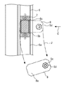
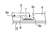
図1〜図6はこの発明の実施の形態1によるエレベータのかご室を説明するもので、図1はかご室における薄形省スペースに構成された天井部の全体構成を概略的に示す断面図、図2は図1の丸で囲むA部を拡大して示す断面図、図3は図2に矢印Bで示す係止部の平面図、図4は図3の係止部を矢印C方向から見た側面図、図5は図1に示す照明板を図1の矢印D方向から見たときの要部構成を説明する図、図6は照明板を着脱するときに図5の状態から所定角度回動させた状態を示す図である。なお、各図を通じて同一符号は同一部分を示している。
1 to 6 illustrate an elevator cab according to
図において、エレベータのかご室1の天井2は、天井本体を構成する天蓋21と、この天蓋21の下側に所定の間隔をあけて設けられたかご室意匠面を構成する吊天井部22とで構成され、吊天井部22の中央部には、この例では長方形状の開口部22aが設けられている。また、該開口部22aの上方に位置する天蓋21部分には、蛍光ランプ3等の照明器具を取り付けるための照明天蓋23が設けられ、該照明天蓋23下部の空間でかご内照明部4が形成されている。吊天井部22の開口部22a内側上面部には、天井2の意匠品を構成する照明板5の着脱時のガイド及び固定のための、吊天井部22の剛性確保を兼ねるL形のガイド部材6が、開口部22aの4辺に沿ってそれぞれ配置されている。
In the figure, a ceiling 2 of an
また、各ガイド部材6の長手方向中央部には、照明板5を重力方向に保持するためのマグネットラッチからなる係止部7がそれぞれ固着されている。なお、マグネットラッチの磁力は特に限定されるものではないが、例えば約5〜10kg相当/個のものは用いることができる。
上記照明板5は意匠性を向上させるために、この例では例えばアクリル樹脂などの透光性の板材で形成され、周囲4箇所に配設されたスペーサ5aを介して段になるように離間された大小2枚の楕円形板51、52からなっている。上側の楕円形板51におけるスペーサ5a設置部の上面には、上端部に磁性材料からなる水平翼状の取付金である係止体8が固着された同様のスペーサ5bがそれぞれ配設され、下側の楕円形板52の底面から上方向に、該楕円形板52、スペーサ5a、上側の楕円形板51、スペーサ5b、及び係止体8と順次挿通された4本の化粧ネジ5cと、固定ナット5dとで相互に固定されて全体が一体的に構成されている。
In addition, a
In this example, the
上記係止体8は、図2、図5に示すように先端部8aが照明板5の中心部に対し何れも外側を向くように取り付けられ、それぞれ係止部7に対して重力方向に係止されると共に磁力にて吸着され、スペーサ5a、5b、化粧ネジ5cなどを用いて一体化された照明板5を天井2に係止する。上記L形のガイド部材6は、立辺が開口部22a側に位置するように設けられ、その立辺に、該立辺の高さが図4に示すように半分程度に形成された、係止体8が回動されるときのスライドガイド部6aと、回動された係止体8が係止部7の部分で重力方向に移動するように切り欠かれた段部6bと、回動された係止体8が係止部7の部分を行き過ぎないように回動角度を制限するストッパー部6cが形成されている。
As shown in FIGS. 2 and 5, the
また、開口部22aの照明天蓋23には、照明板5を着脱するときに、図5、図6に示すように反時計方向に所定角度回動させたときに、照明板5に設けた係止体8が開口部22aを上下方向に通過できる位置を知らせるためのガイド9a、9bが対角線方向に2箇所設けられている。なお、このガイド9a、9bは上端部が照明天蓋23に固定され、下端部が吊天井部22の面位置近傍まで伸びて形成され、係止体8をスムーズに天井2内のかご内照明部4に挿入させる機能を有しており、また係止体8と蛍光ランプ3とが接触しないようにして、接触によるキズ及び破損を防止する機能も有している。なお、かご室1の側方部には壁11が設けられている(図1)。
Further, engaging the
次に、上記のように構成された実施の形態1の動作について説明する。まず、照明板5本体を天井部に固定する場合、照明板5の長径方向に設置されている2つの係止体8が、かご内照明部4の照明天蓋23に設置されているガイド9a、9bと開口部22aの隙間Eに位置するように矢印F方向に回動させて略図6の角度に合わせた後、照明板5を上方に持上げて4つの係止体8が何れも開口部22aの中に入るように挿入する。次に、照明板5を図6の時計方向に回動させることによって、水平方向に突出されている係止体8がガイド部材6のスライドガイド部6aの上端に乗る。作業者は容易に照明板5本体を回転スライドさせることが出来る。このとき、係止体8がスライドガイド部6aの上端をスライドする。
Next, the operation of the first embodiment configured as described above will be described. First, when fixing the main body of the
さらに時計方向に回動させることによって、係止体8はガイド部材6のストッパー部6cに接触する。ストッパー部6cは照明板5本体がそれ以上回転スライド出来なく、また照明板が天井に対して意匠的に最適になる位置に施工されている。ストッパー部6cに接触した係止体8はスライドガイド部5bから離れる為、照明板5の自重によりガイド部材6に施工された段部6bに落とし込まれ、該段部6bに設置された係止部7に重力と磁力による吸着力によって係止され、照明板5本体は天井部に固定される。図4に示す一点鎖線の矢印Gは係止体8の装着時の軌跡を示している。
Further, the
また、照明板5を取り外すときは、装着時と反対の手順において作業される。即ち、図4の一点鎖線の矢印Hで示す軌跡のように、係止体8が係止部7の吸着力に抗して上方向に外れるように照明板5を持上げた後、スライドガイド部6aに沿って図3の反時計方向に矢印Jのように回動させ、係止体8がガイド9a、9bに当たる時点で、4つの係止体8が開口部22aを通過できるようになるので、照明板5を下方に下げることで取り外すことができる。照明板5の着脱の際、照明板5の上下方向の移動に要するストロークは、図4に示すように、薄形省スペースに形成された天井の高さの範囲内に収まっている。
Moreover, when removing the
上記のように、実施の形態1によれば、薄型省スペースに構成された天井2のかご内照明部4の開口部22aを塞ぐ照明板5の着脱作業において、照明板5を単に持上げ、回動させるだけで、安全かつ容易に照明板5の係止体8が開口部22aから着脱できる。このため、工具を使用する必要がない。これによって従来の難解な照明器具交換作業を容易化することができる他、次のような付随効果も得られる。
As described above, according to the first embodiment, in the attaching / detaching operation of the
1)ランプ器具の交換スペースを最小限に押さえることが可能なので、かご内照明部4の深さを意匠性が損なわれることなく小さく出来、従ってエレベータレイアウトを最小限のスペースに収めながら、簡易的構造で、蛍光ランプ3などの照明器具、照明板5などの保守、交換が容易になる。
2)例えば、吊り下げタイプ等の高級意匠からなる照明板などであっても、その着脱をかご室1内から容易に実施することが可能となり、突き上げ等のイタズラに対しても、回転スライド方式を採用し、ガイド部材6のスライドガイド部6aの距離も確保しているため、照明板5は安全に天井2本体に固定され照明板5が落下することなく保持できる。
1) Since the replacement space for the lamp fixture can be kept to a minimum, the depth of the illuminating section 4 in the car can be reduced without impairing the design, and thus the elevator layout can be kept simple while keeping the elevator layout to a minimum. The structure facilitates maintenance and replacement of lighting fixtures such as the
2) For example, it is possible to easily attach and detach an illumination plate made of a high-grade design such as a hanging type from the inside of the
なお、上記照明板5、ガイド部材6、係止部7及び係止体8などの形状や構造、設置個数などは実施の形態で例示したものに限定されないことは言うまでもない。例えば、係止部7を突出体、係止体8を係止部7に嵌合する凹部によって構成し、あるいは照明板5を立体的な形状にするなど、この発明の精神の範囲内で種々の変形や変更が可能である。また、係止部7をマグネットラッチで構成したが、必ずしも磁力で吸着されるものに限定されるものではなく、例えば機械的なばねアクションを利用するものなど、他の係止手段を用いても差し支えない。
Needless to say, the shape and structure of the
なお、マグネットを用いた場合、吸着したものを離間させるときの最初の段階でに大きな力を要するので、イタズラや振動などに対しては有効である。また、照明板5の係止体8としてマグネットを用い、係止部7を磁性体としてもよいことは言うまでもない。また、マグネットラッチからなる係止部7を、吊天井部22の開口部22a内側上面に設置した補強材を兼ねるガイド部材6に設けたが、開口部22aの近傍であれば他の位置、部材に設けても差し支えない。
Note that when a magnet is used, a large force is required at the initial stage when separating the attracted object, which is effective against mischief and vibration. Needless to say, a magnet may be used as the locking
1 かご室、 2 天井、 21 天蓋、 22 吊天井部、 22a 開口部、 23 照明天蓋、 3 蛍光ランプ、 4 かご内照明部、 5 照明板、 51、52 楕円形板、 5a、5b スペーサ、 5c 化粧ネジ、 5d 固定ナット、 6 ガイド部材、 6a スライドガイド部、 6b 段部、 6c ストッパー部、 7 係止部(マグネットラッチ)、 8 係止体(水平翼)、 8a 先端部、 9a、9b ガイド、 11 壁。
DESCRIPTION OF
Claims (3)
この開口部を覆うように配設された照明板と、
上記開口部の近傍に設けられた上記照明板を重力方向に保持するための係止部と、
上記照明板に設けられ上記開口部との水平面方向の相対角度が所定角度のときに上記開口部を上方向に通過し、通過後所定角度回動したときに上記係止部に係止されて上記照明板を固定する係止体と、
上記開口部の内側上面部に設けられたL形の部材からなり、上記係止体が上記係止部に係止されているときは上記照明板の回動を阻止し、上記照明板を上方に移動して上記係止体が上記係止部から離間したときは上記照明板の回動を許すガイド部材と、を備え、
上記ガイド部材は、上記L形の立辺が上記開口部側に位置するように設けられ、その立辺に、該立辺の高さが半分程度に形成され上記係止体が回動されるときのスライドガイド部と、回動された上記係止体が上記係止部の部分で重力方向に移動するように切り欠かれた段部と、回動された上記係止体が係止部の部分を行き過ぎないように回動角度を制限するストッパー部とが形成されていることを特徴とするエレベータのかご室。 An opening for illumination provided in the ceiling of the cab;
An illumination plate arranged to cover the opening;
A locking portion for holding the illumination plate provided in the vicinity of the opening in the direction of gravity;
When the relative angle in the horizontal plane direction with respect to the opening provided on the lighting plate is a predetermined angle, the opening passes through the opening upward. A locking body for fixing the lighting plate ;
It consists of an L-shaped member provided on the inner upper surface of the opening, and when the locking body is locked to the locking portion, the lighting plate is prevented from rotating and the lighting plate is A guide member that allows the lighting plate to rotate when the locking body is separated from the locking portion.
The guide member is provided such that the L-shaped upright side is located on the opening side, and the height of the upright side is formed about half on the upright side, and the locking body is rotated. The slide guide portion, the stepped portion in which the rotated locking body moves in the direction of gravity at the portion of the locking portion, and the rotated locking body is the locking portion. The elevator cab is formed with a stopper portion that limits the rotation angle so as not to go too far .
Priority Applications (1)
| Application Number | Priority Date | Filing Date | Title |
|---|---|---|---|
| JP2006078206A JP4929774B2 (en) | 2006-03-22 | 2006-03-22 | Elevator cab |
Applications Claiming Priority (1)
| Application Number | Priority Date | Filing Date | Title |
|---|---|---|---|
| JP2006078206A JP4929774B2 (en) | 2006-03-22 | 2006-03-22 | Elevator cab |
Publications (2)
| Publication Number | Publication Date |
|---|---|
| JP2007254062A JP2007254062A (en) | 2007-10-04 |
| JP4929774B2 true JP4929774B2 (en) | 2012-05-09 |
Family
ID=38628697
Family Applications (1)
| Application Number | Title | Priority Date | Filing Date |
|---|---|---|---|
| JP2006078206A Expired - Fee Related JP4929774B2 (en) | 2006-03-22 | 2006-03-22 | Elevator cab |
Country Status (1)
| Country | Link |
|---|---|
| JP (1) | JP4929774B2 (en) |
Families Citing this family (1)
| Publication number | Priority date | Publication date | Assignee | Title |
|---|---|---|---|---|
| JP7352460B2 (en) * | 2019-12-16 | 2023-09-28 | 株式会社日立製作所 | Car and elevator |
Family Cites Families (5)
| Publication number | Priority date | Publication date | Assignee | Title |
|---|---|---|---|---|
| JPS63116616A (en) * | 1986-11-06 | 1988-05-20 | 株式会社クボタ | Stem cutter in fruits and vegetables harvesting hand |
| JPH09237515A (en) * | 1996-02-29 | 1997-09-09 | Matsushita Electric Works Ltd | Recessed luminaire |
| JPH10297847A (en) * | 1997-04-28 | 1998-11-10 | Mitsubishi Electric Corp | Lighting system for elevator car |
| JP4496400B2 (en) * | 2000-05-30 | 2010-07-07 | 三菱電機株式会社 | Elevator car lighting equipment |
| JP2003073058A (en) * | 2001-09-03 | 2003-03-12 | Toshiba Elevator Co Ltd | Riding car of elevator |
-
2006
- 2006-03-22 JP JP2006078206A patent/JP4929774B2/en not_active Expired - Fee Related
Also Published As
| Publication number | Publication date |
|---|---|
| JP2007254062A (en) | 2007-10-04 |
Similar Documents
| Publication | Publication Date | Title |
|---|---|---|
| JP4929774B2 (en) | Elevator cab | |
| JP5201553B2 (en) | Elevator car lighting device | |
| JP5523151B2 (en) | Elevator hall lantern equipment | |
| JP2014234291A (en) | Car room and car room lighting device of elevator | |
| JP6116444B2 (en) | Lighting plate fall prevention device for ceiling lighting device in elevator cab, ceiling lighting device provided with the same, and method for removing lighting plate of ceiling lighting device | |
| EP3299329B1 (en) | Elevator car | |
| JP2005163384A (en) | Lower vibration preventing device for top-hinged swinging door | |
| JP5003031B2 (en) | Elevator cab ceiling | |
| JP5959304B2 (en) | Elevator car ceiling equipment | |
| JP2005104691A (en) | Ceiling luminaire device for elevator cab | |
| JP2011068452A (en) | Elevator lighting system | |
| JP7352460B2 (en) | Car and elevator | |
| CN211545609U (en) | Elevator device | |
| JP2013159440A (en) | Lighting system for elevator | |
| JP6279107B2 (en) | Elevator hall lantern equipment | |
| KR101879689B1 (en) | Elavator type lighting tower | |
| JP2016166076A (en) | Ceiling luminaire in elevator car | |
| JP2765463B2 (en) | Elevator car ceiling lighting system | |
| JP6272562B2 (en) | Elevator cab illuminating device and its installation method | |
| JP7141993B2 (en) | Lid mounting structure for ceiling inspection equipment of railway vehicles | |
| JP5376521B2 (en) | In-car lighting device | |
| CN112399957B (en) | Ceiling device of elevator and car of elevator | |
| JP6240292B1 (en) | Car ceiling lighting system | |
| JP4593595B2 (en) | Suspension lower swing device | |
| JP5846794B2 (en) | Elevator car ceiling equipment |
Legal Events
| Date | Code | Title | Description |
|---|---|---|---|
| A621 | Written request for application examination |
Free format text: JAPANESE INTERMEDIATE CODE: A621 Effective date: 20080904 |
|
| A977 | Report on retrieval |
Free format text: JAPANESE INTERMEDIATE CODE: A971007 Effective date: 20110803 |
|
| A131 | Notification of reasons for refusal |
Free format text: JAPANESE INTERMEDIATE CODE: A131 Effective date: 20110809 |
|
| A521 | Written amendment |
Free format text: JAPANESE INTERMEDIATE CODE: A523 Effective date: 20110907 |
|
| TRDD | Decision of grant or rejection written | ||
| A01 | Written decision to grant a patent or to grant a registration (utility model) |
Free format text: JAPANESE INTERMEDIATE CODE: A01 Effective date: 20120117 |
|
| A01 | Written decision to grant a patent or to grant a registration (utility model) |
Free format text: JAPANESE INTERMEDIATE CODE: A01 |
|
| A61 | First payment of annual fees (during grant procedure) |
Free format text: JAPANESE INTERMEDIATE CODE: A61 Effective date: 20120130 |
|
| R150 | Certificate of patent or registration of utility model |
Ref document number: 4929774 Country of ref document: JP Free format text: JAPANESE INTERMEDIATE CODE: R150 Free format text: JAPANESE INTERMEDIATE CODE: R150 |
|
| FPAY | Renewal fee payment (event date is renewal date of database) |
Free format text: PAYMENT UNTIL: 20150224 Year of fee payment: 3 |
|
| R250 | Receipt of annual fees |
Free format text: JAPANESE INTERMEDIATE CODE: R250 |
|
| R250 | Receipt of annual fees |
Free format text: JAPANESE INTERMEDIATE CODE: R250 |
|
| R250 | Receipt of annual fees |
Free format text: JAPANESE INTERMEDIATE CODE: R250 |
|
| LAPS | Cancellation because of no payment of annual fees |