JP4927828B2 - Adaptive timing recovery by general-purpose RAKE reception - Google Patents
Adaptive timing recovery by general-purpose RAKE reception Download PDFInfo
- Publication number
- JP4927828B2 JP4927828B2 JP2008513973A JP2008513973A JP4927828B2 JP 4927828 B2 JP4927828 B2 JP 4927828B2 JP 2008513973 A JP2008513973 A JP 2008513973A JP 2008513973 A JP2008513973 A JP 2008513973A JP 4927828 B2 JP4927828 B2 JP 4927828B2
- Authority
- JP
- Japan
- Prior art keywords
- receiver
- delay
- mode
- rake
- signal
- Prior art date
- Legal status (The legal status is an assumption and is not a legal conclusion. Google has not performed a legal analysis and makes no representation as to the accuracy of the status listed.)
- Expired - Fee Related
Links
- 230000003044 adaptive effect Effects 0.000 title description 2
- 238000011084 recovery Methods 0.000 title 1
- 238000000034 method Methods 0.000 claims description 72
- 238000013442 quality metrics Methods 0.000 claims description 40
- 230000001934 delay Effects 0.000 claims description 28
- 230000008569 process Effects 0.000 claims description 8
- 239000011159 matrix material Substances 0.000 description 33
- 230000004044 response Effects 0.000 description 32
- 230000015572 biosynthetic process Effects 0.000 description 21
- 238000003786 synthesis reaction Methods 0.000 description 21
- 230000015556 catabolic process Effects 0.000 description 17
- 238000006731 degradation reaction Methods 0.000 description 17
- 238000005070 sampling Methods 0.000 description 14
- 239000002131 composite material Substances 0.000 description 8
- 230000005540 biological transmission Effects 0.000 description 7
- 238000004364 calculation method Methods 0.000 description 7
- 238000012545 processing Methods 0.000 description 5
- 238000013459 approach Methods 0.000 description 4
- 238000005311 autocorrelation function Methods 0.000 description 3
- 238000011156 evaluation Methods 0.000 description 3
- 238000005562 fading Methods 0.000 description 3
- 238000010187 selection method Methods 0.000 description 3
- 108010003272 Hyaluronate lyase Proteins 0.000 description 2
- 238000010586 diagram Methods 0.000 description 2
- 238000001914 filtration Methods 0.000 description 2
- 230000007480 spreading Effects 0.000 description 2
- 230000009286 beneficial effect Effects 0.000 description 1
- 238000006243 chemical reaction Methods 0.000 description 1
- 238000004891 communication Methods 0.000 description 1
- 230000006735 deficit Effects 0.000 description 1
- 230000003111 delayed effect Effects 0.000 description 1
- 238000001514 detection method Methods 0.000 description 1
- 230000006866 deterioration Effects 0.000 description 1
- 239000000203 mixture Substances 0.000 description 1
- 238000012986 modification Methods 0.000 description 1
- 230000004048 modification Effects 0.000 description 1
- 230000000644 propagated effect Effects 0.000 description 1
Images


Classifications
-
- H—ELECTRICITY
- H04—ELECTRIC COMMUNICATION TECHNIQUE
- H04B—TRANSMISSION
- H04B1/00—Details of transmission systems, not covered by a single one of groups H04B3/00 - H04B13/00; Details of transmission systems not characterised by the medium used for transmission
- H04B1/69—Spread spectrum techniques
- H04B1/707—Spread spectrum techniques using direct sequence modulation
- H04B1/7097—Interference-related aspects
- H04B1/711—Interference-related aspects the interference being multi-path interference
- H04B1/7115—Constructive combining of multi-path signals, i.e. RAKE receivers
- H04B1/712—Weighting of fingers for combining, e.g. amplitude control or phase rotation using an inner loop
-
- H—ELECTRICITY
- H04—ELECTRIC COMMUNICATION TECHNIQUE
- H04B—TRANSMISSION
- H04B1/00—Details of transmission systems, not covered by a single one of groups H04B3/00 - H04B13/00; Details of transmission systems not characterised by the medium used for transmission
- H04B1/69—Spread spectrum techniques
- H04B1/707—Spread spectrum techniques using direct sequence modulation
- H04B1/7097—Interference-related aspects
- H04B1/711—Interference-related aspects the interference being multi-path interference
- H04B1/7115—Constructive combining of multi-path signals, i.e. RAKE receivers
- H04B1/7117—Selection, re-selection, allocation or re-allocation of paths to fingers, e.g. timing offset control of allocated fingers
-
- H—ELECTRICITY
- H04—ELECTRIC COMMUNICATION TECHNIQUE
- H04B—TRANSMISSION
- H04B2201/00—Indexing scheme relating to details of transmission systems not covered by a single group of H04B3/00 - H04B13/00
- H04B2201/69—Orthogonal indexing scheme relating to spread spectrum techniques in general
- H04B2201/707—Orthogonal indexing scheme relating to spread spectrum techniques in general relating to direct sequence modulation
- H04B2201/7097—Direct sequence modulation interference
- H04B2201/709727—GRAKE type RAKE receivers
Landscapes
- Engineering & Computer Science (AREA)
- Computer Networks & Wireless Communication (AREA)
- Signal Processing (AREA)
- Radio Transmission System (AREA)
- Mobile Radio Communication Systems (AREA)
- Noise Elimination (AREA)
- Cable Transmission Systems, Equalization Of Radio And Reduction Of Echo (AREA)
Description
本発明は、一般に、符号分割多元接続(CDMA)システムのためのRAKE受信機に関する。より詳細に、本発明は、RAKE受信機におけるRAKEフィンガのフィンガ設定を決定する方法と装置に関する。 The present invention relates generally to RAKE receivers for code division multiple access (CDMA) systems. More particularly, the present invention relates to a method and apparatus for determining finger settings for a RAKE finger in a RAKE receiver.
無線通信システムにおいて、送信された信号は、複数の伝搬路(マルチパス)を経由して受信機に届くことがある。従ってこの場合は、受信された信号は、異なった時間シフトをした複数の信号の混成されたものになる。異なった時間シフトを受けた受信信号を、ここでは信号イメージと呼ぶことにすると、これらの信号イメージは、異なった位相と減衰の影響を受けることになる。複数の時間シフトを持つ信号イメージは、受信機のところで、予知できない形で合成され、その結果、信号のフェーディングが起こる。 In a wireless communication system, a transmitted signal may reach a receiver via a plurality of propagation paths (multipath). Therefore, in this case, the received signal is a mixture of a plurality of signals having different time shifts. If the received signals that have undergone different time shifts are referred to herein as signal images, these signal images will be affected by different phases and attenuation. Signal images with multiple time shifts are synthesized in an unpredictable manner at the receiver, resulting in signal fading.
CDMA受信機は、典型的には、マルチパスの伝搬によるフェーディングを克服するために、RAKE受信機を用いる。RAKE受信機の目的は、それぞれの信号イメージを検出して、それらを同位相で合成することである。RAKE受信機は、典型的には、異なった信号イメージを別々に逆拡散するための、複数の、しばしばフィンガと呼ばれる、相関器と、相関器の出力を合成する合成器とを含む。例えば、RAKE受信機は、M個の最も強い信号イメージを検出して合成してもよい。遅延検索器(ディレイサーチャ)は、最も強い信号イメージに対応した遅延を識別するために、受信した信号を処理する。そして、
フィンガ設定プロセッサは、これらの遅延に基づいてフィンガを設定する。フィンガ設定の工程は、RAKEフィンガを信号イメージと時間的に合致するように設定するべく、それぞれのRAKEフィンガに遅延を割り当てる工程を備える。フィンガ設定の簡単な考え方は、遅延検索器により発見されたJ個の最も強い信号イメージの遅延を、それぞれに対応したRAKEフィンガに割り当てる方法である。
CDMA receivers typically use RAKE receivers to overcome fading due to multipath propagation. The purpose of the RAKE receiver is to detect the respective signal images and synthesize them in phase. A RAKE receiver typically includes a plurality of correlators, often called fingers, and a combiner that combines the outputs of the correlators to despread different signal images separately. For example, the RAKE receiver may detect and synthesize the M strongest signal images. The delay searcher (delay searcher) processes the received signal to identify the delay corresponding to the strongest signal image. And
The finger setting processor sets the fingers based on these delays. The finger setting step comprises assigning a delay to each RAKE finger in order to set the RAKE fingers to match the signal image in time. A simple idea of finger setting is to assign the J strongest signal image delays found by the delay searcher to the corresponding RAKE fingers.
典型的には、フィンガ設定は、遅延の関数としての信号電力を与える、ある決められた検索窓(サーチウィンドウ)を通して推定した電力遅延プロファイル(PDP)を生成することより出発する。典型的なPDPを図1に示す。遅延検索器は受信した信号サンプル(サンプリングされた信号)の電力を測定する。サンプリングの間隔によって検索のグリッドが決まり、信号電力の測定によりPDPが決まる。フィンガ設定の1つの方法は、PDPの中で遅延値のピークまたは極大のところ、またはその付近にフィンガを設定する方法である。ここでは、この方法を「ピーク」の方法と呼ぶことにする。理想的には、RAKEフィンガは、PDPのピークに対応した遅延値に正確に設定をされるであろう。しかし、図1に示すように、検索グリッドは、常にはPDPのピークに位置的に一致することはないので、PDPのピークに正確に一致したRAKEフィンガの設定は、常に可能ではない。PDPの中における実際のピークは、検索グリッドのグリッド点(格子点)とグリッド点との間に来るかもしれない。 Typically, finger settings start by generating an estimated power delay profile (PDP) through a certain search window that gives signal power as a function of delay. A typical PDP is shown in FIG. The delay searcher measures the power of the received signal sample (sampled signal). The search grid is determined by the sampling interval, and the PDP is determined by measuring the signal power. One method of setting a finger is to set a finger at or near the peak or maximum of the delay value in the PDP. Here, this method is called a “peak” method. Ideally, the RAKE finger would be accurately set to a delay value corresponding to the peak of the PDP. However, as shown in FIG. 1, since the search grid does not always coincide with the PDP peak in position, it is not always possible to set a RAKE finger that exactly coincides with the PDP peak. The actual peak in the PDP may be between the grid points (grid points) of the search grid.
実際のチャネル遅延に対する検索グリッドの位置設定は、動作特性に影響を与える。この点を示すために、シンプルで平坦な(単一タップ)チャネルを考えてみる。CDMA受信機は、そのような信号を受信すると、受信した信号と時間シフトした拡散符号との相関を取ることを試みる。検索器によって与えられる時間シフト(遅延量)は検索グリッドの分解能の関数である。もし、グリッドの位置設定がチャネルの遅延量に一致していれば、他の全ての符号の寄与は直交しているので干渉はない。しかし、もし、グリッドの位置設定がチャネルの遅延に一致していなければ、直交性が失われて、他の符号の寄与は干渉となって現れる。例えば、16−QAMのような高次の変調方式が用いられた非常に高いデータレートの場合には、位置設定の誤差の与える影響は、劇的でさえもある。これは、この変調方式が自己干渉に非常に敏感だからである。このように、伝搬路の遅延が2つのサンプリング間隔の中間にあるときには、動作性能の劣化は厳しいものになることがある。従って、データ処理量としては、RAKEフィンガに割り当てられた遅延値が信号イメージの伝搬路遅延に対応している場合の高いデータレートのときの処理量と、RAKEフィンガに割り当てられた遅延値が伝搬路遅延に対応していない場合のより低いデータレートのときの処理量との間を変動することになる。 The search grid position relative to the actual channel delay affects the operating characteristics. To illustrate this point, consider a simple, flat (single tap) channel. When a CDMA receiver receives such a signal, it attempts to correlate the received signal with a time-shifted spreading code. The time shift provided by the searcher is a function of the resolution of the search grid. If the grid position setting matches the delay amount of the channel, there is no interference because the contributions of all other codes are orthogonal. However, if the grid positioning does not match the channel delay, the orthogonality is lost and the contribution of other codes appears as interference. For example, for very high data rates where higher order modulation schemes such as 16-QAM are used, the impact of positioning errors is even dramatic. This is because this modulation scheme is very sensitive to self-interference. Thus, when the propagation path delay is in the middle of the two sampling intervals, the performance degradation may be severe. Therefore, as the data processing amount, the processing amount at a high data rate when the delay value assigned to the RAKE finger corresponds to the propagation delay of the signal image and the delay value assigned to the RAKE finger are propagated. The amount of processing varies at a lower data rate when the path delay is not supported.
本発明は、受信機の動作モードを決定するための方法に関する。一般に、この方法は、遅延検索器を用いて、受信機によって受信された信号の中の信号イメージを識別する工程を備える。そして、受信機の中のプロセッサが、それぞれ、単一遅延の受信機モードと、複数遅延の受信機モードとに対して適用するべき、第1および第2の信号品質メトリックを決定する。プロセッサはその後、第1および第2の信号品質メトリックを比較することに基づいて、単一遅延の受信機モードと、複数遅延の受信機モードのどちらかを選択する。単一遅延の受信機モードが選択された場合、受信機は単一の遅延値を用いて信号イメージを処理する。複数遅延の受信機モードが選択された場合、受信機は複数の遅延値を用いて信号イメージを処理する。 The present invention relates to a method for determining an operating mode of a receiver. In general, the method comprises identifying a signal image in a signal received by a receiver using a delay searcher. A processor in the receiver then determines first and second signal quality metrics to apply to the single delay receiver mode and the multiple delay receiver mode, respectively. The processor then selects between a single delay receiver mode and a multiple delay receiver mode based on comparing the first and second signal quality metrics. If a single delay receiver mode is selected, the receiver processes the signal image with a single delay value. If the multiple delay receiver mode is selected, the receiver processes the signal image using multiple delay values.
本発明の1つの実施形態では、受信機は、RAKE受信機を備える。本発明は、このRAKE受信機の中の、フィンガ設定(フィンガ配置)と重み係数を決定するための方法に関する。この典型的な実施形態に従えば、遅延検索器は受信信号の中の信号イメージを識別するように設定され、フィンガ設定プロセッサは、単一遅延の受信機モードか複数遅延の受信機モードかを選択するように設定される。フィンガ設定プロセッサは、単一遅延の受信機モード、および、複数遅延の受信機モードに対して、それぞれ、第1および第2の信号品質メトリックを生成し、最もよいメトリックを与える受信機モードを選択するように設定される。受信機モードの選択は、受信された信号の中に検出された、全ての信号イメージ対して実行されてもよいし、または選択されたある信号イメージのみに対して実行されてもよい。例えば、受信機モードの選択は、最も強い信号イメージのみに対して実行されてもよいし、事前に決められた基準を満足した全ての信号イメージに対して実行されてもよい。モード選択機能は選択的に可能(イネーブル)または不能(ディスエーブル)とされてもよい。例えば、モード選択機能は、単一の信号イメージを含む非分散性のチャネルに対してのみ可能とし、2つ以上の信号イメージを含む分散性のチャネルに対しては不能とすることでもよい。他の実施形態においては、他の基準を考えてもよい。例えば、モード選択機能は、ある選択された変調方式とデータレートに対してのみ可能とするのでもよい。 In one embodiment of the invention, the receiver comprises a RAKE receiver. The present invention relates to a method for determining finger settings (finger placement) and weighting factors in this RAKE receiver. According to this exemplary embodiment, the delay searcher is configured to identify a signal image in the received signal, and the finger setting processor determines whether the receiver mode is single delay or multiple delay receiver mode. Set to select. Finger setting processor generates first and second signal quality metrics for single delay receiver mode and multiple delay receiver mode, respectively, and selects the receiver mode that gives the best metric Set to do. The selection of the receiver mode may be performed for all signal images detected in the received signal, or may be performed only for certain selected signal images. For example, the selection of the receiver mode may be performed only for the strongest signal image, or may be performed for all signal images that satisfy a predetermined criterion. The mode selection function may be selectively enabled (enabled) or disabled (disabled). For example, the mode selection function may be enabled only for non-dispersive channels containing a single signal image and disabled for dispersive channels containing more than one signal image. In other embodiments, other criteria may be considered. For example, the mode selection function may be enabled only for a selected modulation scheme and data rate.
もう一例の実施形態では、受信機はチップ等化受信機を備える。チップ等化受信機には、受信信号をフィルタリングするためのJ個のタップが設定される。フィルタのタップ数とそれぞれのフィルタのタップに割り当てられる遅延量は、信号品質メトリックの評価に基づいて、適応的に決められる。 In another example embodiment, the receiver comprises a chip equalization receiver. In the chip equalization receiver, J taps for filtering the received signal are set. The number of filter taps and the amount of delay assigned to each filter tap are adaptively determined based on the evaluation of the signal quality metric.
本発明は、RAKE受信機またはチップ等化受信機のフィンガの設定を決定する、方法と装置に関する。ここに用いているRAKE受信機という語は、ここに参考文献として用いる、アメリカ合衆国特許No.6,363,104、で説明されている、汎用RAKE(G−RAKE)受信機を含む。本発明は、単入力単出力(SISO)受信機、多入力単出力(MISO)受信機、および、多入力多出力(MIMO)受信機に応用される。 The present invention relates to a method and apparatus for determining finger settings for a RAKE receiver or chip equalization receiver. As used herein, the term RAKE receiver refers to US Pat. 6,363,104, including a general purpose RAKE (G-RAKE) receiver. The present invention applies to single-input single-output (SISO) receivers, multiple-input single-output (MISO) receivers, and multiple-input multiple-output (MIMO) receivers.
図2は、本発明の典型的な実施形態に従ったRAKE受信機10を含む無線受信機5を示す。無線受信機5は、受信機アンテナ12、受信機フロントエンド14、RAKE受信機10、および、復号器28、とを備える。RAKE受信機10は、RAKEプロセッサ30、マルチパス信号の中の信号イメージを検出する複数個のRAKEフィンガ16、および、合成されたRAKE出力信号を生成するためにRAKEフィンガ16の出力を合成する加重ネットワーク22、とを備える。復号器28は、合成されたRAKE出力信号を復号する。受信機フロントエンド14は、信号処理を行うべきベースバンド信号を生成するために、アンテナ12からの受信信号の、フィルタリングを行い、周波数ダウンコンバートを行い、サンプリングを行う。サンプリング間隔は、例えば、チップ周期Tcの半分の長さでよい。受信機フロントエンド14からのサンプルされた信号は、1つ以上のRAKEフィンガ16に入力される。RAKEフィンガ16の機能は、選択された信号イメージ、典型的にはL個の最も強い信号イメージ、の逆拡散を行うことである。図3で見るように、それぞれのRAKEフィンガ16は、遅延素子18と相関器20を備える。遅延素子18は、RAKEプロセッサ30で決定された可変に設定可能な遅延量を、受信した信号に与えることによって、選択された信号イメージの遅延値と一致するようにフィンガ16を設定する。相関器20は、受信した信号を逆拡散するために、遅延が与えられた信号と、希望信号についての既知の拡散系列との相関を取る機能を持つ。相関を取った結果、受信した信号の中に含まれる非希望信号が受信機にとって雑音として現れる。加重ネットワーク22は、それぞれのRAKEフィンガ16から出力される逆拡散信号に重みを付与して(加重して)から合成する。統計量として合成出力を決定するために、すなわち、ここで言うRAKE出力信号を生成するために、加重素子24がそれぞれのRAKEフィンガ出力に重み係数を乗算し、RAKE合成器26がそれらの重み付けされたRAKEフィンガ出力を合成する。RAKE出力信号は復号器28に入力され、復号器は、RAKE出力信号を復号し、もとの送信された信号を推定する。
FIG. 2 shows a wireless receiver 5 that includes a
RAKEプロセッサ30は、RAKEフィンガ16の数と設定を決定する。また、それぞれのRAKEフィンガ出力に与える合成のための重みを決定する。図4は、本発明の典型的な実施形態に従った、RAKEプロセッサを示す。RAKEプロセッサ30は、遅延検索器32とフィンガ設定プロセッサ34とを備える。遅延検索器32は、受信信号の中に含まれる個々の信号イメージを識別し、それぞれの信号イメージに関して遅延量を求める。より詳細に言うならば、遅延検索器32は、事前に決められた検索窓(サーチウィンドウ)を通して得られた受信信号サンプル(サンプリングされた受信信号)の電力を測定することにより、図1に示されるような電力遅延プロファイルを生成する。サンプリング間隔は1チップ周期かそれ以下でよい。図1はサンプリング間隔を1/2チップ周期と仮定した場合の電力遅延プロファイルである。信号イメージを検出する1つの手法は、PDPの中の極大値を検出し、その極大値を定義された閾値と比較することである。これらの極大の遅延値は、受信されたマルチパス信号の中の、信号イメージの伝搬路の遅延値であると考えることができる。検出された信号イメージの伝搬路遅延はフィンガ設定プロセッサ34に入力される。フィンガ設定プロセッサ34は、遅延検索器32によって供給される伝搬路遅延の推定値に基づきRAKEフィンガ16の数と設定を決定する。フィンガ設定プロセッサ34は、さらに、それぞれのRAKEフィンガ出力に適用するべき重み係数を算出する。
The
フィンガ設定プロセッサ34は、フィンガ設定器35、チャネル推定器36、合成重み生成器38、および、メトリック計算器40を含む。フィンガ設定器35は、伝搬路検索器32によって報告される伝搬路遅延の推定値に基づいて、RAKEフィンガ16の設定を決定する。従来のRAKE受信機では、RAKEフィンガ16は、典型的には、L個の最も大きい遅延に割り当てられる。G−RAKE受信機では、どの伝搬路の遅延量にも対応しない受信信号の検出のために、さらなるRAKEフィンガ16が付加されて用いられることもある。チャネル推定器36は、割り当てられたそれぞれのRAKEフィンガに対して、送信機から受信機までの伝搬チャネルの推定値(チャネル推定)を生成する。チャネル推定は合成重み生成器38に供給される。合成重み生成器38は、RAKEフィンガ出力に適用すべき合成重みを算出する。合成重み生成器38は、例えば、最大比合成(MRC)の基準を基本として合成する加重を算出してもよい。MRC合成については、合成重みは、それぞれのRAKEフィンガに対する相関器20の出力のところでの信号電力、または信号電力対干渉電力比(SIR)に基づいて求められる。あるRAKEフィンガ16の信号のSIRが低い場合には、小さい重み係数が割り当てられるであろう。逆に、あるRAKEフィンガ16の信号のSIRが高い場合には、大きな重み係数が割り当てられるであろう。全面的なG−RAKE(full G−RAKE)の合成では、合成重み生成器38は、RAKEフィンガ間にわたる劣化相関値を算出し、劣化共分散行列Rを生成する。合成重み生成器38は、劣化共分散行列(impairment covariance matrix)Rの逆行列にチャネル推定器36から得られるチャネル推定のベクトルh^を乗じて加重ベクトル(weight vector)wを生成する。加重ベクトルwの要素は、RAKEフィンガ16の出力に対する重み係数である。
The
ある場合には、遅延検索器32は受信信号の中で主要な1つの信号イメージを検出してもよい。この状況は、たとえば、送信機から受信機までが直接の見通し内伝搬路である時に起こり得る。主要な信号イメージは、1つの信号イメージが検出されてそれが非分散性のチャネルを示しているときに、存在するであろう。もし、チャネルが分散性であり、2つ以上の信号イメージが検出されれば、主要な信号イメージの存在は、検出した信号イメージの相対信号電力またはSIRに基づいて決定されてもよい。もし、最も強い信号イメージの、信号電力またはSIRが、他のものより事前に決められた量だけ超えていれば、主要な信号イメージが存在すると決定されてもよい。
In some cases, the
主要な信号イメージが存在するときには、信号品質メトリックに基づいて受信機モードを選択するという適応的なフィンガ設定のアルゴリズムを用いることにより、受信の機能を改善することができる。検索グリッドまたは遅延推定グリッドが、主要な信号イメージの伝搬路遅延と合致していないときには、PDPの中におけるピークの近傍に複数のRAKEフィンガを設定することにより、受信機能は改善される。この場合は、複数のRAKEフィンガからの出力の合成は、内挿を行う形になる。最終的な結果は、伝搬路遅延に設定された単一のRAKEフィンガに近似される。検索グリッドが伝搬路遅延と合致して、PDPの中のピークが伝搬路遅延の位置にある、または非常に近くにある場合には、この付加的なRAKEフィンガ16の使用は不必要である。
When the main signal image is present, the reception function can be improved by using an adaptive finger setting algorithm that selects the receiver mode based on the signal quality metric. When the search grid or delay estimation grid does not match the propagation delay of the main signal image, the reception function is improved by setting multiple RAKE fingers near the peak in the PDP. In this case, the synthesis of the outputs from the plurality of RAKE fingers is performed by interpolation. The final result approximates a single RAKE finger set to the propagation path delay. Use of this
本発明の1つの視点に従えば、フィンガ設定プロセッサ34は、16−QAMにおけるように、送信された信号、または、それに関わる統計量の推定値を作り出すために、合成を行うRAKEフィンガの数を適応的に決定する。フィンガ設定プロセッサ34は、フィンガ設定に対する種々の考え方により、または、受信機モードを仮定して、信号品質メトリックを評価する。第1の信号品質メトリックは、ここでは単一フィンガメトリックと呼ぶことにする。このメトリックは、推定されたPDPの中におけるピークの位置に設定された単一のRAKEフィンガ16を用いる、単一フィンガ受信機モードに対して決定される。第2の信号品質メトリックは、ここでは複数フィンガメトリックと呼ぶことにする。このメトリックは、推定されたPDPの中におけるピークの近傍に設定された複数のフィンガ16を用いる、複数フィンガ受信機モードに対して決定される。ある実施形態では、複数フィンガメトリックは、推定されたPDPのピークの中央に設定された、等間隔に配された3つのRAKEフィンガ16に基づいて算出される。フィンガの間隔は、典型的には、サンプリングの間隔の倍数である。この場合、サンプリンググリッドはフィンガを設定するためのグリッドとして用いられる。しかし、当業者は、フィンガ設定のグリッドはサンプリンググリッドと異なっていてもよいと理解するであろう。いずれの場合も、RAKEフィンガ16の間隔は、ナイキストの基準よりは小さくなければならない。フィンガ設定プロセッサ34は、メトリックの評価に基づいて、単一フィンガ受信機モードか複数フィンガ受信機モードかのどちらかを選択する。
In accordance with one aspect of the present invention,
本発明は、単一フィンガ受信機モードか2以上の数の複数フィンガ受信機モードかのどちらかを選択するのにも用いられてもよい。例えば、単一フィンガメトリックに加えて、3フィンガメトリック、および5フィンガメトリックが求められてもよい。さらに、異なった伝搬路遅延を仮定することにより、それぞれの複数フィンガ受信機モードに対して、種々なるチャネルの条件が考慮されてもよい。 The present invention may also be used to select either a single finger receiver mode or two or more multiple finger receiver modes. For example, in addition to a single finger metric, 3 finger metrics and 5 finger metrics may be determined. Furthermore, various channel conditions may be considered for each multiple finger receiver mode by assuming different propagation path delays.
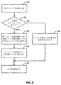
図5は、RAKE受信機10において、フィンガ設定を決定する典型的な手順を示す。遅延検索器32が受信した信号の中から信号イメージを検出する(ブロック52)。そして、主要な信号イメージが存在するか否かを判定する(ブロック54)。もし、複数の信号イメージがあって、主要な信号イメージが存在しなければ、フィンガ設定は従来の方法で実行されてよい(ブロック56)。もし、主要な信号イメージが存在すれば、これはただ1つの信号イメージが存在する場合であり、フィンガ設定プロセッサ34は、受信機モードとして、例えば、単一フィンガ受信機モードか複数フィンガ受信機モードかを選択する。受信機モードを決定するために、フィンガ設定プロセッサ34は、単一フィンガ受信機モード、および、複数フィンガ受信機モードに対する信号対干渉比(SIR)の推定値、または、その他の信号品質メトリックを算出する(ブロック58)。次に、フィンガ設定プロセッサ34は、単一フィンガモード、複数フィンガモードに対して計算したSIRを比較し、SIRを最大にするモードを選択することにより、受信機モードを選択する(ブロック60)。選択された受信機モードが受信信号の復調に用いられる(ブロック62)。
FIG. 5 shows an exemplary procedure for determining finger settings in the
RAKE受信機の中でのSIRの推定は、従来知られているいずれの方法を用いてもよい。例えば、合成受信機では、SIRは次式で推定されてもよい。 Any conventionally known method may be used for estimating the SIR in the RAKE receiver. For example, in a combined receiver, the SIR may be estimated by the following equation:

ここに、wは合成重みベクトル(combining weight vector)(またはスカラー)、h^は推定された純応答ベクトル(net response vector)(またはスカラー)、Rは推定された劣化共分散行列(impairment covariance matrix)(またはスカラー)である。SIRの算出に用いる合成重みwは試行的な合成重みであってよい。RAKEフィンガ出力を合成するのに用いる合成重みwは、より正確な情報に基づいていてもよい。また、SIRの計算に用いたものと異なっていてもよい。 Here, w is a combining weight vector (or scalar), h ^ is an estimated pure response vector (or scalar), and R is an estimated degradation covariance matrix. ) (Or scalar). The synthesis weight w used for calculating the SIR may be a trial synthesis weight. The synthesis weight w used to synthesize the RAKE finger output may be based on more accurate information. Further, it may be different from that used for the calculation of SIR.
SIRを決定する最初のステップは、フィンガ設定を決定することである。単一フィンガ受信機モードでは、RAKEフィンガ16のフィンガ遅延量が、遅延検索器32から報告される遅延量のところに設定される。複数フィンガ受信機モードでは、RAKEフィンガ16の望ましい数J(典型的には奇数)が、伝搬路検索器32によって報告されるPDPのピークに対応した遅延の中央に置かれるようにしてもよい。フィンガの間隔Δはナイキストの基準(WCDMAの場合は、<0.8チップ)を満足しなければならない。例として、3つのRAKEフィンガ16を仮定すると、フィンガ設定プロセッサ34は、そのうちの1つを、PDPの中のピークに対応した遅延値d1に設定してもよい。残った2つのフィンガは、d1の前後の、事前に決められたオフセット量Δのところに設定することもできるだろう。オフセット量Δは、例えば、3/4チップ、または1/2チップでよい。一般的な原則として、RAKEフィンガ16の数Jが奇数の時には、(J−1)/2個のフィンガ16は中央のフィンガからΔずつ増加させたところに設定し、(J−1)/2個のフィンガ16は中央のフィンガからΔずつ減少させたところに設定する。フィンガ設定が決定した後に、フィンガ設定プロセッサ34は、合成重みベクトルw、純応答ベクトルh^、および、劣化共分散行列Rを算出する。
The first step in determining the SIR is to determine the finger settings. In the single finger receiver mode, the finger delay amount of the
合成重みベクトルw、純応答ベクトルh^、および、劣化共分散行列Rの算出の方法は、従来技術でよく知られているので、ここでは簡単にまとめることにする。RAKEフィンガ16に対する純応答ベクトルh^、および、劣化共分散行列Rが与えられれば、合成重みベクトルwは、次式に従って算出される。
Since the method of calculating the composite weight vector w, the pure response vector ^, and the degradation covariance matrix R is well known in the prior art, it will be briefly summarized here. Given a pure response vector ^ and a degraded covariance matrix R for the
純応答ベクトルh^は、逆拡散を行ったパイロットシンボルからチャネル推定器36により推定されてもよい。純応答ベクトルh^は長さJのベクトルを備える。そのベクトルの要素はJ個のRAKEフィンガに対応したチャネル係数を備える。スロットインデックスjにおける純応答ベクトルh^は下式で与えられる。 The pure response vector ^ may be estimated by the channel estimator 36 from the despread pilot symbols. The pure response vector h ^ comprises a vector of length J. The elements of the vector have channel coefficients corresponding to J RAKE fingers. The pure response vector h ^ at the slot index j is given by
ここに、x(m,j)は、逆拡散されたパイロットシンボルの、j番目のスロットのm番目のシンボルに対応したベクトルであり、s(m)は、時間インデックスmに送信された既知のパイロットシンボルである。Npはパイロットサンプルの数で、それによりチャネルが推定される。 Where x (m, j) is the vector of the despread pilot symbol corresponding to the mth symbol in the jth slot, and s (m) is the known transmitted at time index m It is a pilot symbol. N p is the number of pilot samples, thereby estimating the channel.
式(1.3)は、それぞれのRAKEフィンガ16における純チャネル応答の、雑音を含む推定値を与える。純応答ベクトルh^のより正確な推定値はパルスの形を考慮に入れて算出できる。初めに、純応答ベクトルh^が、式(1.3)に従ってJ個のフィンガの遅延値に対して計算される。その後、L個の伝搬路遅延が考慮される。ここに、LはJ以下の数である。このL個の伝搬路遅延はここに説明する方法で推定されてもよい。それぞれの推定された伝搬路遅延に対する伝送媒体応答ベクトル(medium response vector)g^は次式で与えられる。
Equation (1.3) gives a noisy estimate of the pure channel response at each
ここに、Aは、推定された伝搬路遅延におけるパルス波形の自己相関を与えるパルス波形自己相関行列である。AはJ×Lの行列であり、Aの{i,j}要素は、自己相関関数rff(di−τj)により与えられる。ここに、diはフィンガの遅延値であり、τjは推定された伝搬路遅延値である。伝送媒体応答ベクトルg^から、G−RAKEのJ個のフィンガ16に対する実効純応答ベクトル(effective net response vector)h〜が次式に従って生成されてもよい。
Here, A is a pulse waveform autocorrelation matrix that gives the autocorrelation of the pulse waveform in the estimated propagation path delay. A is a J × L matrix, and the {i, j} element of A is given by the autocorrelation function r ff (d i −τ j ). Here, d i is the delay value of the finger, and τ j is the estimated propagation path delay value. From the transmission medium response vector ^, an effective net response vector h˜ for the
![]()
![]()
ここに、Bはパルス波形の自己相関で表したパルス波形自己相関行列である。RAKEフィンガ16の数Jは推定された伝搬路遅延の数Lと異なってもよいことに注意を要する。BはJ×Lの行列であり、Bの{j,l}要素は自己相関関数rff(dj−τl)により与えられる。ここに、djはフィンガの遅延値であり、τlは推定された伝搬路遅延値である。G−RAKE受信機の計算には、実効純応答ベクトルh〜がh^の代わりに用いられてもよい。
Here, B is a pulse waveform autocorrelation matrix expressed by the autocorrelation of the pulse waveform. Note that the number J of
劣化共分散行列Rの推定値(推定劣化共分散行列)R^は、純応答ベクトルh^から算出されてもよい。または代替として、劣化共分散行列Rは、実効純応答ベクトルh〜から算出されてもよい。推定劣化共分散行列R^は、次式により純応答ベクトルh^から算出することができる。 The estimated value (estimated degradation covariance matrix) R ^ of the degradation covariance matrix R may be calculated from the pure response vector h ^. Or alternatively, impairment covariance matrix R may be calculated from the effective net response vector h ~. The estimated degradation covariance matrix R ^ can be calculated from the pure response vector h ^ by the following equation.
![]()
![]()
式(1.6)に従って算出された推定劣化共分散行列R^は、それぞれ、式(1.2)および式(1.1)に従って、合成重みwとSIRを算出するのに用いることもできる。または代替として、次式により、フィルタリングされた推定共分散行列を算出し、それを用いて式(1.2)および式(1.1)に従って、それぞれ、合成重みwとSIRを算出することもできる。
R−(k)=γR−(k−1)+(1−γ)R^(k)
ここに、γ=(0.99)N Pである。
The estimated degradation covariance matrix R ^ calculated according to equation (1.6) can also be used to calculate the composite weight w and SIR according to equation (1.2) and equation (1.1), respectively. . Alternatively, the filtered estimated covariance matrix can be calculated by the following equation, and the combined weight w and SIR can be calculated according to the equations (1.2) and (1.1), respectively. it can.
R− (k) = γR− (k−1) + (1−γ) R ^ (k)
Here, a γ = (0.99) N P.
アメリカ合衆国特許出願No.10/800167、2004年、3月12日、および/または、アメリカ合衆国特許出願No.60/685825、2005年、5月31日、の中で説明されているパラメトリックの手法もまた劣化の相関を計算するのに用いることができる。これらの出願は、参考特許として、本発明に添付してある。このパラメトリックの手法を用いると、劣化共分散行列Rは次式に従って算出される。 United States Patent Application No. 10/800167, March 12, 2004, and / or United States patent application no. The parametric approach described in 60/658825, May 31, 2005, can also be used to calculate the degradation correlation. These applications are attached to the present invention as reference patents. When this parametric method is used, the degradation covariance matrix R is calculated according to the following equation.
ここに、Rlは干渉相関行列であり、これは、複数のユーザによる干渉により起こされる、干渉の相関を表すものである。RNは、RAKEフィンガ16間にある雑音の相関を表す雑音相関行列である。パラメータαとβは、フィッティングパラメータである。パラメータαは、全基地局の電力のパイロットチャネルの電力に対する比である。βは、白色雑音の電力で、背景雑音をモデル化した雑音とモデル化されない干渉(セル間と、おそらくは、システムGSM/EDGE間の干渉)の和である。フィッティングパラメータのαとβは未知の量であるが、下式に対する最小2乗の解を求めて推定することができる。
Here, R l is an interference correlation matrix, which represents the correlation of interference caused by interference by a plurality of users. R N is the noise correlation matrix representing the noise correlation in between
フィッティングパラメータαとβは、瞬時値、または、フィルタを通した値でよいし、または、1シンボル毎、1スロット毎、1フレーム毎を基本として算出された値でもよい。フィッティングパラメータαとβとが分かれば、劣化相関行列Rは式(1.7)に従って算出される。干渉相関行列の{i,j}要素は、下式で与えられる。 The fitting parameters α and β may be instantaneous values or values that have passed through a filter, or may be values calculated on a symbol-by-symbol, slot-by-slot, or frame-by-frame basis. If the fitting parameters α and β are known, the deterioration correlation matrix R is calculated according to the equation (1.7). The {i, j} element of the interference correlation matrix is given by the following equation.
ここに、glとgqは、式(1.4)で与えられる伝送媒体応答ベクトルg^のl番目、q番目の要素であり、diとdjはフィンガの遅延量、τlとτqは伝搬路の遅延量である。rff(t)は受信機フィルタの自己相関関数、Tcはチップの周期である。雑音相関行列の{i,j}要素は下式で与えられる。 Here, g l and g q are the l-th and q-th elements of the transmission medium response vector g ^ given by equation (1.4), d i and d j are finger delay amounts, τ l and τ q is a delay amount of the propagation path. r ff (t) is the autocorrelation function of the receiver filter and T c is the period of the chip. The {i, j} element of the noise correlation matrix is given by the following equation.
![]()
![]()
図6はSIRを算出する典型的な方法を示す。この方法では、合成重みがパラメトリックの手法で計算される。最初に、フィンガ設計器35が遅延探索器32によって報告されるピークに基づいてフィンガの遅延値を決める(ブロック102)。チャネル推定器36が、チャネルを推定し、式(1.3)に従って純応答ベクトルh^を算出する(ブロック104)。そして、式(1.4)に従って伝送媒体応答ベクトルg^を算出する(ブロック106)。伝送媒体応答ベクトルg^は合成重み生成器38に供給され、純応答ベクトルh^は合成重み生成器38とメトリック計算器40の両方に供給される。合成重み生成器38は式(1.9)に従って干渉相関行列Rlを算出し、式(1.10)に従って雑音相関行列RNを算出する(ブロック108)。つぎに、合成重み生成器38はフィッティングパラメータαおよびβを決める(ブロック110)。そして、劣化共分散行列Rを算出する(ブロック112)。合成重み生成器38は、純応答ベクトルh^と劣化共分散行列Rに基づき式(1.2)に従って、合成重みwを算出してもよい(ブロック114)。最後に、メトリック計算器40が、式(1.1)に従って、複数フィンガ受信機モードに対するSIRを算出する(ブロック116)。単一フィンガ受信機モードでは古典的なRAKE(例えば、MRC−RAKE)の解である。合成重み、純チャネル応答、および、劣化共分散は全てスカラー量である。単一受信機モードに対する純チャネル応答は、長さJのベクトルh^の要素であり、伝搬路検索器から報告される遅延量(dl)に対応している。合成重みは、純チャネル応答の共役複素数である。劣化共分散は、複数フィンガモードに対して計算される劣化共分散行列Rの要素であり、伝搬路検索器により報告される遅延量の自分自身との共分散(R(dl,dl))に対応している。式(1.2)では単一フィンガのSIRを決めるためにこれらの量が用いられている。受信機モードを選択するために、複数フィンガのSIRは、単一フィンガのSIRと比較される。
FIG. 6 shows an exemplary method for calculating the SIR. In this method, the synthesis weight is calculated by a parametric method. Initially,
複数フィンガ受信機モードでは、複数のRAKEフィンガ16が主要な信号イメージの遅延の周囲に設定される。そして、SIRの算出のために、異なった手法が取られてもよい。1つの手法は、ここではフルオーダー(全次数)の手法と呼ぶことにして、信号イメージの伝搬路をJ個の伝搬路を持つ分散性のチャネルとして取り扱う。そして、RAKEフィンガ16は伝搬路の数と等しいJ=L個のフィンガを用いることにする。この場合には、もし、伝搬路の遅延量τlがフィンガの遅延量dlに等しいと仮定すれば、SIRの計算は直接求めることができる。第2の手法は、ここでは削減されたオーダー(半次数)の手法と呼ぶことにして、主要な信号イメージの伝搬路の数をLと仮定して、Lよりも大きいJ個のRAKEフィンガ16を用いる。この場合には、フィンガの遅延量djと仮定した伝搬路の遅延量τlのずれ(オフセット)が決められる必要がある。フィンガの遅延量djは、J個のフィンガグリッドを遅延検索器32によって報告される遅延のピークの中央にあわせることにより決まる。フィンガ設定プロセッサ34は、1個以上の伝搬路遅延τlを仮定して、仮定した伝搬路遅延τlのそれぞれの組に対して、フィンガの遅延値のオフセットdj−τlを決定する。この操作は、フィンガ設定のグリッドを伝搬路遅延に対して相対的にシフトさせるのと等価である。従って、主要な信号の伝搬路をモデル化するのに、2伝搬路モデルを用いるとすれば、そして、3つのフィンガを用いるとすれば、仮定した伝搬路遅延τlのそれぞれの組に対して、結果として、それぞれのフィンガ16に対して2つずつ、合計6フィンガのオフセットが設定されるであろう。仮定したそれぞれの伝搬路遅延τlのそれぞれ組に対して、メトリックが計算されて、最もよいメトリックを持つ伝搬路遅延τlの組がSIRの算出に用いられる。純応答ベクトルh^、劣化共分散行列R、合成重みwは、これまでに説明した方法で算出される。
In the multiple finger receiver mode,
上記の半次数チャネルのモデルを説明するために、主要な信号イメージの伝搬路をモデル化するのに単一伝搬路モデルを用いること、および、受信機は3つのRAKEフィンガ16を用いることを仮定する。フィンガの遅延値として、中央のフィンガ16の遅延値をd1で表し、それぞれその右と左のフィンガ16の遅延値を、それぞれ、d1+Δとd1−Δで表す。図7に示すように、伝搬路の遅延τlの設定に関していくつかの仮定値ができあがる。1つは、伝搬路検索器32から報告された遅延値d1であり、その他の仮定値は、±ΔHの単位で表される。ΔHに対する典型的な値は、チップ周期の1/16である。図7では、仮定された伝搬路の遅延値はxで示されている。このように、伝搬路の遅延値τlとしてN個の値が仮定されれば、+ΔHの増分に対しては(N−1)/2個の値、−ΔHの増分に対しては(N−1)/2個の値が仮定されることになる。それぞれの仮定値からの各フィンガの遅延値のオフセットは、{d1+Δ−τl, d1−τl, d1−Δ−τl}で与えられる。
To illustrate the above half-order channel model, assume that a single channel model is used to model the main signal image channel, and that the receiver uses three
仮定した伝搬路遅延の評価と最もよい仮定値の選択には、種々のメトリックを用いることが可能である。1つの手法は、それぞれの仮定値に対して、チャネル係数を推定し、対数尤度を計算する方法である。対数尤度を最小にする仮定値が選択される。図8はこの手法を図示している。フィンガのグリッドを遅延検索装置32から報告されるPDPの中におけるピークの中央に合わせることにより、フィンガの遅延値が決められる(ブロック200)。カウンタは計数値を0に設定して初期化される(ブロック202)。それぞれの仮定値に対してチャネル係数が生成され(ブロック204)、それぞれの仮定値に対する対数尤度メトリックが算出される(ブロック206)。対数尤度メトリックについては、「Optimizing the Performance of Limited Copmplexity RAKE Receivers」、Bottomley、ほか、第48回IEEE Vehicle Technology Conference Proceedings、Ottawa、Canada、1998年5月、および、アメリカ合衆国特許第6839378号の中で説明されている。サンプリング位置に対応していない逆拡散値を得るには内挿を用いることができる。ブロック206において対数尤度を算出した後に、フィンガ設定プロセッサ34はカウンタの計数値nを増して行く(ブロック208)。そして、希望する仮定値の数Nと計数値nを比較する(ブロック210)。もし、n<Nであれば、次の仮定値へと手順が繰り返される。もし、n=Nであれば、フィンガ設定プロセッサ34は、対数尤度メトリックを最小にする仮定値を選択する(ブロック212)。複数フィンガ受信機モードに対する最もよい仮定値を選択した後に、複数フィンガ受信機モードに対するSIRが、上記で述べたように計算される。そして、単一フィンガ受信機モードに対するSIRと比較される。そして、フィンガ設定プロセッサはSIRを最大にする受信機モードを選択する。
Various metrics can be used to evaluate the assumed channel delay and select the best hypothesis value. One method is a method of estimating a channel coefficient and calculating a log likelihood for each assumed value. An assumed value that minimizes the log likelihood is selected. FIG. 8 illustrates this technique. The finger delay value is determined by aligning the finger grid to the center of the peak in the PDP reported from the delay searcher 32 (block 200). The counter is initialized with the count value set to 0 (block 202). Channel coefficients are generated for each hypothesis value (block 204) and a log likelihood metric for each hypothesis value is calculated (block 206). Logarithmic likelihood metrics are described in "Optimizing the Performance of Limited Competency RAKE Receivers", Bottomley, et al. Explained. Interpolation can be used to obtain a despread value that does not correspond to the sampling position. After calculating the log likelihood in
仮定した伝搬路の遅延値を選択するもうひとつの手法は、複数フィンガ受信機モードに対する最適な仮定値を選択する方法として、SIRをメトリックとして用いる方法である。図9はこの方法を図示している。遅延検索器32により報告された遅延値にフィンガグリッドを中央合わせすることによりフィンガ遅延値が決定される(ブロック300)。その後、フィンガ設定プロセッサ34は純応答ベクトルh^と雑音相関行列RNとを算出する(ブロック302)。雑音相関行列RNは仮定した伝搬路遅延とは独立である点に注意を要する。フィンガ設定プロセッサ34は、カウンタの計数値nを0にすることによりカウンタを初期化する(ブロック304)。フィンガ設定プロセッサ34は、その後、それぞれの仮定値に対してステップ306からブロック316までを実行する。フィンガ設定プロセッサ34は、それぞれの仮定値に対して、伝送媒体係数(ブロック306)、干渉相関行列Ri(ブロック308)、フィッティングパラメータαとβ(ブロック310)、劣化共分散行列R^(ブロック312)、合成重みw(ブロック314)、および、SIR(ブロック316)を算出する。G−RAKEの合成が行われる場合には、SIRは、SIR=h^Hwと簡単化される。SIRが算出(ブロック316)された後に、フィンガ設定プロセッサ34は、カウンタの計数値を増加させて(ブロック318)、希望する仮定値の数と計数値を比較する(ブロック320)。もし計数値が希望する数値より小さければ、フィンガ設定プロセッサ34は、ブロック306からブロック316までを計数値が希望する数値になるまで繰り返す。計数値が希望する数値に到達すると、フィンガ設定プロセッサ34は、SIRを最大にする仮定値を選択する(ブロック322)。フィンガ設定プロセッサ34はその後、ブロック322で選択した仮定値に対するSIRと、単一フィンガ受信機モードに対するSIRとを比較し、受信機モードを選択する。
Another method of selecting the assumed propagation path delay value is a method of using SIR as a metric as a method of selecting an optimum assumed value for the multi-finger receiver mode. FIG. 9 illustrates this method. The finger delay value is determined by centering the finger grid to the delay value reported by the delay searcher 32 (block 300). Thereafter, the
複数フィンガ受信機モードに対する遅延値の仮定値を選択する第3の手法は、距離メトリックを基本にした方法である。この方法は図10に図示されている。フィンガ設定プロセッサ34は、フィンガグリッドを、遅延検索器32から報告されたPDPの中のピークに対応する遅延に中央合わせをすることにより、フィンガの遅延値を決める(ブロック400)。フィンガ設定プロセッサ34は、純チャネル応答ベクトルh^を算出する(ブロック402)。純チャネル応答ベクトルh^はフィンガグリッドの関数であるが、伝搬路遅延の仮定値の関数ではないことに注意を要する。フィンガ設定プロセッサ34は、カウンタの計数値を0に設定してカウンタを初期化する(ブロック404)。その後、フィンガ設定プロセッサ34は、それぞれの仮定値に対してステップ406から410までを実行する。フィンガ設定プロセッサ34は、それぞれの仮定値に対してそれぞれのRAKEフィンガの伝送媒体係数g^nを算出し(ブロック406)、それぞれのRAKEフィンガに対する実効純係数h〜 nを算出し(ブロック408)、さらに、純チャネル応答ベクトル係数と実効純チャネル応答ベクトル係数との間の距離メトリックを算出する(ブロック410)。距離メトリックは(|h^−h〜 n|2)で与えられるユークリッド距離メトリックであってもよいし、または、(h^−h〜 n)HR−1(h^−h〜 n)で与えられる雑音相関を表す距離メトリックであってもよい。フィンガ設定プロセッサ34は、距離メトリックを算出(ブロック410)した後に、カウンタの計数値を増加させて(ブロック412)、計数値を仮定値の希望する数値と比較する(ブロック414)。もし計数値が希望する数値に達していなければ、フィンガ設定プロセッサ34はブロック406からブロック410までを、計数値が希望する数値に達するまで繰り返す。計数値が希望する数値に到達すると、フィンガ設定プロセッサ34は、距離メトリックを最小にする仮定値を選択する。
A third technique for selecting hypothesized delay values for the multiple finger receiver mode is a distance metric based method. This method is illustrated in FIG. The
図10に示した方法を簡単化するために、上記で与えたユークリッド距離メトリックの変形を用いることもできる。ユークリッド距離メトリックは、|h^Hyi|2に従って算出されてもよい。ここに、yi=ri/√ri Tri、ri=[rff(d1+Δ−τl),rff(d1−τl),rff(d1−Δ−τl)]Tである。yiは、オフセットした遅延値を持つ全ての仮定値に対して事前に算出されてもよいことに注意すべきである。
In order to simplify the method shown in FIG. 10, a variation of the Euclidean distance metric given above can also be used. The Euclidean distance metric may be calculated according to | h ^ H y i | 2 . Here, y i = r i / √r i T r i, r i = [r ff (
複数フィンガ受信機モードに対する最もよい伝搬路遅延の仮定値を決めるために、どのメトリックを用いるかに関わらず、1伝搬路モデルが仮定されれば、また、仮定した伝搬路の遅延値がサンプリング点に対応すれば、RAKEフィンガ16のうち2つのフィンガは取り除かれてもよく、単一のフィンガが推定された伝搬路遅延値に設定される。もし、推定された伝搬路遅延値が単一フィンガ受信機モードに対する伝搬路遅延値と等しいならば、先の2つの手法を比較する必要はない。推定された伝搬路遅延がサンプリング点に対応しない時には、復調の時にどちらの手法を用いるかを決定するために、複数フィンガ受信機モードに対するSIRと、単一フィンガ受信機モードに対するSIRとは比較されなければならない。
Regardless of which metric is used to determine the best propagation path delay assumption for the multi-finger receiver mode, if a single propagation path model is assumed, the assumed propagation path delay value is also the sampling point. , Two of the
これまでは、単一伝搬路チャネルの場合を説明したが、本発明は、分散性のチャネルにも適用することができる。例えば、単一フィンガイメージ受信機モードと複数フィンガイメージ受信機モードとの選択を行うための、上記で説明したモード選択の方法は、最も強力な信号イメージだけ、または、全ての信号イメージ、または、事前に決められた基準を満足する全ての信号イメージ、に対して適用することができる。マルチパスチャネルのなかで適用する場合は、SIRの算出は割り当てられた全てのフィンガを考慮に入れなければならない。例えば、もし2伝搬路チャネルがあって、受信機が主要な伝搬路に対して1つまたは3つのフィンガを設定しようとする時には、SIRは、主要な信号イメージに対して、または、より弱い伝搬路に対して、1つまたは3つのフィンガを考慮して算出されるであろう。主要な伝搬路は、フェーディング値の長時間平均、または、瞬時値によって決められてよい。 So far, the case of a single propagation channel has been described, but the present invention can also be applied to a dispersive channel. For example, the mode selection method described above for selecting between single-finger image receiver mode and multiple-finger image receiver mode may be the strongest signal image only, or all signal images, or It can be applied to all signal images that meet predetermined criteria. When applied in a multipath channel, the SIR calculation must take into account all assigned fingers. For example, if there are two channel channels and the receiver tries to set one or three fingers for the main channel, the SIR may be for the main signal image or for weaker propagation. For roads, it will be calculated taking into account one or three fingers. The main propagation path may be determined by a long-time average of fading values or an instantaneous value.
上記で説明した実施形態では、受信機はRAKE受信機であることが仮定されていた。当業者は本発明がチップ等化受信機にも適用可能であると認識するであろう。図11は本発明の1つの実施形態に従ったチップ等化受信機500を示す。チップ等化受信機500は、等化器フィルタ502、逆拡散器520、および、フィルタプロセッサ530、を備える。等化器フィルタ502は、逆拡散を行う前の、フィルタを通した信号を生成するために、受信した信号サンプルをフィルタリングする。等化フィルタ502はFIRフィルタを備え、FIRフィルタはJ個のタップ506を持つ遅延素子504を備える。タップの出力506は加重素子508により加重されてもよく、その後に合成器510により合成される。代替として、合成器510はタップ出力506を直接に合成してもよい。フィルタを通った信号は逆拡散器520により逆拡散される。フィルタプロセッサ530は等化器フィルタ502に対するタップの遅延量とフィルタの係数を決定する。タップの遅延量は上記で議論したフィンガの遅延値に対応している。また、フィルタ係数は上記で議論した合成重みに対応している。RAKE受信機における実施形態に示すように、フィルタプロセッサ530は、メトリックの評価に基づいて等化器フィルタに対するタップ数Jを決定する。同様に、フィルタプロセッサ530は、J個のタップのフィルタ係数を決定する。
In the embodiment described above, it was assumed that the receiver is a RAKE receiver. Those skilled in the art will recognize that the present invention is also applicable to chip equalization receivers. FIG. 11 shows a chip equalization receiver 500 according to one embodiment of the present invention. The chip equalization receiver 500 includes an
本発明は、多元の受信アンテナ、および/または、多元の送信アンテナにも発展させることができる。多元の受信アンテナの場合には、上記で説明した方法が、それぞれの受信アンテナに個別に適用されてもよい。それらは組み合わせて適用されてもよく、これは、HSDPA、すなわち、WCDMAの高速ダウンリンクパケットデータモードのような、干渉によって動作性能が決まるような場合に有益であろう。例えば、単一伝搬路チャネルと2つの受信アンテナを仮定した場合には、受信機では以下の4つの手法を比較することができるであろう。
1)1つのフィンガをアンテナAに設定し、1つのフィンガをアンテナBに設定する。
2)1つのフィンガをアンテナAに設定し、3つのフィンガをアンテナBに設定する。
3)3つのフィンガをアンテナAに設定し、1つのフィンガをアンテナBに設定する。
4)3つのフィンガをアンテナAに設定し、3つのフィンガをアンテナBに設定する。
もし、2つのアンテナに対するサンプリングが同時であれば、上記の2と3の選択肢は取り除かれる。
The present invention can be developed to a multiple receiving antenna and / or a multiple transmitting antenna. In the case of multiple receiving antennas, the method described above may be applied individually to each receiving antenna. They may be applied in combination, which may be beneficial in cases where the operational performance is determined by interference, such as HSDPA, ie WCDMA high speed downlink packet data mode. For example, assuming a single channel channel and two receive antennas, the receiver would be able to compare the following four approaches:
1) One finger is set to antenna A and one finger is set to antenna B.
2) Set one finger to antenna A and set three fingers to antenna B.
3) Set three fingers to antenna A and set one finger to antenna B.
4) Set three fingers to antenna A and set three fingers to antenna B.
If the sampling for two antennas is simultaneous, the above choices 2 and 3 are removed.
そのかわり、2つのアンテナに対するサンプリングが交互に行われるならば、上記の1と4の選択肢は取り除かれる。G−RAKEに対するメトリックを算出するときには、両方のアンテナを基本にした結合SIRの計算が用いられてもよい。
Instead, the
多元の送信アンテナに関わるシナリオには2つのものがある。1つはソフトハンドオフである。この場合、それぞれの送信信号に対して、フィンガの設定は別々に行われてよい。もう1つシナリオは送信ダイバーシティーである。この場合は、双方の伝搬路の到着時間が同時であるという仮定に基づいて、上記で説明した方法がそれぞれの送信信号に対して個別に適用されてもよいし、または、一緒にして適用されてもよい。加重の生成とSIRの算出に関する詳細はアメリカ合衆国特許出願第10/800167号、2004年3月12日、に述べられている。 There are two scenarios involving multiple transmit antennas. One is soft handoff. In this case, the fingers may be set separately for each transmission signal. Another scenario is transmit diversity. In this case, based on the assumption that the arrival times of both propagation paths are simultaneous, the method described above may be applied individually to each transmitted signal or applied together. May be. Details regarding weight generation and SIR calculation are described in US patent application Ser. No. 10/800167, Mar. 12, 2004.
上記で説明した典型的な実施形態では、受信機モードの選択は復調の前に行われる。本発明のほかの実施形態では、複数の復調が並列に行われた後にメトリックの算出を行うことが考慮されてもよい。最良のメトリックを与える復調信号が復号器に送られる。また、復調と復号とが異なった手法で同時に実行されてもよい。もし、最初の方法がうまく行かなければ(例えば、CRCのような誤り検出コードが動作しなければ)、第2の方法を試みることができる。もし、受信機モードの選択が、復調の後であるが復号の前に行われるならば、選択は平均二乗誤差(MSE)の尺度を基本にして行うことができる。例えば、2つの受信機モードがRAKE合成に用いられるならば、それぞれの受信機モードに対するMSEは、シンボルを検出し、希望するRAKE合成信号を再生し、そして、再生された信号とRAKE合成された信号との間の誤差を調べる、ことにより推定されてもよい。 In the exemplary embodiment described above, the receiver mode selection is performed prior to demodulation. In other embodiments of the present invention, it may be considered to calculate a metric after multiple demodulations are performed in parallel. The demodulated signal giving the best metric is sent to the decoder. Further, demodulation and decoding may be performed simultaneously by different methods. If the first method does not work (eg, if an error detection code such as CRC does not work), the second method can be attempted. If the receiver mode selection is made after demodulation but before decoding, the selection can be made on the basis of a mean square error (MSE) measure. For example, if two receiver modes are used for RAKE combining, the MSE for each receiver mode detects the symbol, reproduces the desired RAKE combined signal, and is RAKE combined with the recovered signal. It may be estimated by examining the error between the signals.
受信機の処理に関わる負荷を軽減するために、本発明は適応的に適用されてもよい。例えば、一例として、本発明のモード選択の方法は、少数の信号伝搬路のあるときのみ適用されてもよい。変調方式やデータレートのような、さらなる基準を考慮に入れることもできる。本発明は、より高次の変調方式、より高速のデータレートのときに、より大きな有利さを提供するものである。データレートは、用いられる、変調方式、拡散率、および、マルチコードの数によって決まる。例えば、上記で説明した方法は、遅延検索器32がただ1つの伝搬路を見出したとして、そのときのマルチコードの数の拡散率に対する比が1.5より大きい場合に適用されてもよい。
The present invention may be applied adaptively to reduce the load associated with receiver processing. For example, as an example, the mode selection method of the present invention may be applied only when there are a small number of signal propagation paths. Additional criteria such as modulation scheme and data rate can also be taken into account. The present invention provides greater advantages at higher order modulation schemes and higher data rates. The data rate depends on the modulation scheme, spreading factor, and number of multicodes used. For example, the method described above may be applied when the
本発明は、当然のことながら、本発明の基本的な特性から逸脱することなく、ここで特別に述べた以外の分野においても実行することができる。ここで述べた実施形態は、全ての観点からして例示目的であって、限定的なものではないと考えるべきである。そして、別記の特許請求の範囲の意味と等価の範囲から由来する全ての変形は本発明に包含されると意図されるべきである。 The present invention may, of course, be carried out in other fields than those specifically set forth herein without departing from the basic characteristics of the invention. The embodiments described herein are to be considered in all respects as illustrative and not restrictive. All modifications derived from the meaning equivalent to the scope of the claims are intended to be included in the present invention.
Claims (32)
前記受信信号に含まれる信号イメージを識別するステップと、
単一の遅延量を用いて前記識別された信号イメージを処理する単一遅延の受信機モードについて、第1の信号品質メトリックを決定するステップと、
複数の遅延量を用いて前記識別された信号イメージを処理する複数遅延の受信機モードについて、第2の信号品質メトリックを決定するステップと、
前記第1の信号品質メトリックと前記第2の信号品質メトリックとを比較するステップと、
前記第1の信号品質メトリックと前記第2の信号品質メトリックとの比較結果に基づいて、前記単一遅延の受信機モードと前記複数遅延の受信機モードとのいずれかを選択するステップと
を含むことを特徴とする方法。A method for determining an operating mode in a receiver for demodulating a received signal, comprising:
Identifying a signal image included in the received signal;
Determining a first signal quality metric for a single delay receiver mode that processes the identified signal image with a single amount of delay;
Determining a second signal quality metric for a multi-delay receiver mode that processes the identified signal image using a plurality of delay amounts;
Comparing the first signal quality metric and the second signal quality metric;
Selecting either the single delay receiver mode or the multiple delay receiver mode based on a comparison result between the first signal quality metric and the second signal quality metric. A method characterized by that.
電力遅延プロファイルを作成するステップと、
前記電力遅延プロファイル内での電力の極大値を検出するステップと
を含むことを特徴とする請求項1に記載の方法。The identifying step comprises:
Creating a power delay profile;
And detecting a local maximum value of power within the power delay profile.
前記単一遅延の受信機モードは、
前記RAKE受信機が備える単一のRAKEフィンガ又は前記チップ等化受信機が備える単一の遅延タップを、前記極大値に対応した遅延に配置することを含み、
前記複数遅延の受信機モードは、
前記RAKE受信機が備える複数のRAKEフィンガ又は前記チップ等化受信機が備える複数の遅延タップを、前記極大値の近傍に位置する複数の遅延に配置することを含む
ことを特徴とする請求項2に記載の方法。The receiver has a RAKE receiver or chip equalization receiver,
The single delay receiver mode is:
Placing a single RAKE finger provided in the RAKE receiver or a single delay tap provided in the chip equalization receiver at a delay corresponding to the maximum value,
The multi-delay receiver mode is:
3. A plurality of RAKE fingers provided in the RAKE receiver or a plurality of delay taps provided in the chip equalizing receiver are arranged at a plurality of delays located in the vicinity of the maximum value. The method described in 1.
前記複数遅延の受信機モード用の前記第2の信号品質メトリックを決定する前記ステップは、
2つ以上の経路遅延のセットを仮定するステップと、
前記経路遅延のセットの各セットについてメトリックを算出するステップと、
前記メトリックに基づいて、前記仮定された経路遅延のセットを選択するステップと、
前記選択された経路遅延のセットを使用して、前記第2の信号品質メトリックを算出するステップと
を含むことを特徴とする請求項1に記載の方法。The second signal quality metric for the multi-delay receiver mode includes a reduced order model of the signal image that includes fewer path delays than the number of delays used in the multi-delay receiver mode. Based on
Determining the second signal quality metric for the multi-delay receiver mode;
Assuming a set of two or more path delays;
Calculating a metric for each set of path delay sets;
Selecting the assumed set of path delays based on the metric;
2. The method of claim 1, comprising calculating the second signal quality metric using the selected set of path delays.
復号に失敗すると第2の受信機モードを使用して、前記受信信号について2度目の復号を実行するステップと
をさらに含む
ことを特徴とする請求項1に記載の方法。Decoding the received signal using a selected receiver mode;
2. The method of claim 1, further comprising performing a second decoding on the received signal using a second receiver mode if decoding fails.
前記受信機モードについてのモード選択機能は、非分散性のチャネルについてのみイネーブルにされるか、選択されたデータレートについてイネーブルにされるか、または、選択された変調方式についてイネーブルにされる
ことを特徴とする請求項1に記載の方法。The mode selection function for the receiver mode is selectively enabled or disabled;
The mode selection function for the receiver mode may be enabled only for non-dispersive channels, enabled for selected data rates, or enabled for selected modulation schemes. The method of claim 1, characterized in that:
前記受信信号は、前記単一遅延の受信機モード及び前記複数遅延の受信機モードにおいて並行してRAKE合成され、前記信号品質メトリックは、復号するために、RAKE合成されたシンボルの推定値を選択する際に使用される
ことを特徴とする請求項13に記載の方法。The first and second signal quality metrics are calculated after performing RAKE combining in the single delay receiver mode and the multiple delay receiver mode;
The received signal is RAKE combined in parallel in the single delay receiver mode and the multiple delay receiver mode, and the signal quality metric selects an estimate of the RAKE combined symbol for decoding. The method according to claim 13, wherein the method is used in the process.
前記受信信号に含まれている信号イメージを検出する遅延検索器と、
単一の遅延量を用いて前記検出された信号イメージを処理する単一遅延の受信機モードについて、第1の信号品質メトリックを決定し、複数の遅延量を用いて前記検出された信号イメージを処理する複数遅延の受信機モードについて、第2の信号品質メトリックを決定し、前記第1の信号品質メトリックと前記第2の信号品質メトリックとを比較し、前記第1の信号品質メトリックと前記第2の信号品質メトリックとの比較結果に基づいて、前記単一遅延の受信機モードと前記複数遅延の受信機モードとのいずれかを選択するプロセッサと
を含むことを特徴とする受信機。A receiver that demodulates a received signal including one or more signal images,
A delay searcher for detecting a signal image included in the received signal;
For a single delay receiver mode that processes the detected signal image using a single amount of delay, a first signal quality metric is determined and the detected signal image is determined using multiple amounts of delay. For a multi-delay receiver mode to process, a second signal quality metric is determined, the first signal quality metric is compared with the second signal quality metric, and the first signal quality metric and the second signal quality metric are compared . And a processor for selecting one of the single-delay receiver mode and the multiple-delay receiver mode based on a comparison result with two signal quality metrics.
前記単一遅延の受信機モードは、
前記RAKE受信機が備える単一のRAKEフィンガ又は前記チップ等化受信機が備える単一の遅延タップを、前記極大値に対応した遅延に配置することを含む
ことを特徴とする請求項18に記載の受信機。The receiver has a RAKE receiver or chip equalization receiver,
The single delay receiver mode is:
19. The method of claim 18, further comprising disposing a single RAKE finger included in the RAKE receiver or a single delay tap included in the chip equalization receiver at a delay corresponding to the maximum value. Receiver.
前記複数遅延の受信機モードは、
前記RAKE受信機が備える複数のRAKEフィンガ又は前記チップ等化受信機が備える複数の遅延タップを、前記極大値の近傍に位置する複数の遅延に配置することを含む
ことを特徴とする請求項18に記載の受信機。The receiver has a RAKE receiver or chip equalization receiver,
The multi-delay receiver mode is:
19. The plurality of RAKE fingers provided in the RAKE receiver or the plurality of delay taps provided in the chip equalizing receiver are arranged at a plurality of delays located in the vicinity of the maximum value. As described in the receiver.
前記複数遅延の受信機モードにおいて使用される遅延の数に等しい数の経路遅延を含んだ、前記信号イメージのフルオーダーモデルに基づいて、前記複数遅延の受信機モード用の前記第2の信号品質メトリックを決定するよう構成されている
ことを特徴とする請求項17に記載の受信機。The processor is
The second signal quality metric for the multi-delay receiver mode based on a full order model of the signal image, including a number of path delays equal to the number of delays used in the multi-delay receiver mode. The receiver of claim 17, wherein the receiver is configured to determine
前記複数遅延の受信機モードにおいて使用される遅延の数よりも少ない数の経路遅延を含んだ、前記信号イメージの削減オーダーモデルに基づいて、前記複数遅延の受信機モード用の前記第2の信号品質メトリックを決定するよう構成されており、
さらに、前記プロセッサは、前記複数遅延の受信機モード用の前記第2の信号品質メトリックを決定するために、
2つ以上の経路遅延のセットを仮定し、
前記経路遅延のセットの各セットについてメトリックを算出し、
前記メトリックに基づいて、前記仮定された経路遅延のセットを選択し、
前記選択された経路遅延のセットを使用して、前記第2の信号品質メトリックを算出するよう構成されている
ことを特徴とする請求項17に記載の受信機。The processor is
The second signal quality for the multi-delay receiver mode based on the reduced order model of the signal image, which includes a smaller number of path delays than the number of delays used in the multi-delay receiver mode Configured to determine metrics,
Further, the processor determines the second signal quality metric for the multi-delay receiver mode.
Assuming a set of two or more path delays,
Calculate a metric for each set of sets of path delays;
Selecting the assumed set of path delays based on the metric;
The receiver of claim 17, wherein the receiver is configured to calculate the second signal quality metric using the selected set of path delays.
前記プロセッサは、
前記受信機モードについてのモード選択を非分散性のチャネルについてのみイネーブルにするか、
前記受信機モードについてのモード選択を、選択されたデータレートについてイネーブルにするか、または、
記受信機モードについてのモード選択を、選択された変調方式についてイネーブルにするよう構成されている
ことを特徴とする請求項17に記載の受信機。The processor is configured to selectively enable or disable mode selection for the receiver mode;
The processor is
Enable mode selection for the receiver mode only for non-dispersive channels,
Enable mode selection for the receiver mode for a selected data rate, or
The receiver of claim 17, wherein the receiver is configured to enable mode selection for the selected receiver mode for the selected modulation scheme.
選択された受信機モードを使用して逆拡散された逆拡散値をRAKE合成するRAKE受信機を含み、
前記プロセッサは、フィンガ設定プロセッサを含む
ことを特徴とする請求項17に記載の受信機。The receiver
Including a RAKE receiver for RAKE combining despread values despread using a selected receiver mode;
The receiver of claim 17, wherein the processor includes a finger setting processor.
前記RAKE受信機は、前記受信信号を、前記単一遅延の受信機モード及び前記複数遅延の受信機モードにおいて並行してRAKE合成するよう構成されており、
前記フィンガ設定プロセッサは、前記信号品質メトリックに基づいて復号するために、RAKE合成されたシンボルの推定値を選択するよう構成されている
ことを特徴とする請求項27に記載の受信機。The finger setting processor calculates the first and second signal quality metrics after performing RAKE combining in the single delay receiver mode and the multiple delay receiver mode;
The RAKE receiver is configured to RAKE combine the received signal in parallel in the single delay receiver mode and the multiple delay receiver mode;
28. The receiver of claim 27, wherein the finger configuration processor is configured to select an estimate of a RAKE synthesized symbol for decoding based on the signal quality metric.
前記プロセッサは、フィルタプロセッサを含み、
前記チップ等化受信機は、1つ以上の遅延タップを使用して前記受信信号をフィルタリングするよう構成された等化フィルタを含む
ことを特徴とする請求項17に記載の受信機。The receiver includes a chip equalization receiver,
The processor includes a filter processor;
The receiver of claim 17, wherein the chip equalization receiver includes an equalization filter configured to filter the received signal using one or more delay taps.
Applications Claiming Priority (5)
| Application Number | Priority Date | Filing Date | Title |
|---|---|---|---|
| US68601505P | 2005-05-31 | 2005-05-31 | |
| US60/686,015 | 2005-05-31 | ||
| US11/219,183 | 2005-09-02 | ||
| US11/219,183 US8964912B2 (en) | 2005-05-31 | 2005-09-02 | Adaptive timing recovery via generalized RAKE reception |
| PCT/EP2006/004839 WO2006128609A1 (en) | 2005-05-31 | 2006-05-22 | Adaptive timing recovery via generalized rake conception |
Publications (3)
| Publication Number | Publication Date |
|---|---|
| JP2008543193A JP2008543193A (en) | 2008-11-27 |
| JP2008543193A5 JP2008543193A5 (en) | 2009-07-02 |
| JP4927828B2 true JP4927828B2 (en) | 2012-05-09 |
Family
ID=36778203
Family Applications (1)
| Application Number | Title | Priority Date | Filing Date |
|---|---|---|---|
| JP2008513973A Expired - Fee Related JP4927828B2 (en) | 2005-05-31 | 2006-05-22 | Adaptive timing recovery by general-purpose RAKE reception |
Country Status (7)
| Country | Link |
|---|---|
| US (1) | US8964912B2 (en) |
| EP (1) | EP1886414B1 (en) |
| JP (1) | JP4927828B2 (en) |
| KR (1) | KR101256695B1 (en) |
| CN (1) | CN101185251B (en) |
| TW (1) | TW200705848A (en) |
| WO (1) | WO2006128609A1 (en) |
Families Citing this family (48)
| Publication number | Priority date | Publication date | Assignee | Title |
|---|---|---|---|---|
| GB2370380B (en) | 2000-12-19 | 2003-12-31 | Picochip Designs Ltd | Processor architecture |
| JP4522919B2 (en) * | 2005-07-15 | 2010-08-11 | 三菱電機株式会社 | Equalizer and receiver |
| EP1760901B1 (en) * | 2005-09-01 | 2009-07-22 | Telefonaktiebolaget L M Ericsson (publ) | Method and apparatus for selecting delay values for a RAKE receiver |
| KR100738340B1 (en) * | 2005-12-01 | 2007-07-12 | 한국전자통신연구원 | Detecting method of multiple-input multiple-output system |
| FR2894416B1 (en) * | 2005-12-05 | 2008-02-29 | Commissariat Energie Atomique | METHOD AND DEVICE FOR SELECTING THE SPREAD PARAMETERS OF A CDMA OFDM SYSTEM |
| EP2475106A1 (en) | 2006-02-28 | 2012-07-11 | Rotani Inc. | Methods and apparatus for overlapping mimo antenna physical sectors |
| US20080112511A1 (en) * | 2006-11-10 | 2008-05-15 | Steffen Paul | Receiver |
| US7751463B2 (en) * | 2006-12-05 | 2010-07-06 | Telefonaktiebolaget Lm Ericsson (Publ) | Method and apparatus for suppressing interference based on channelization code power estimation with bias removal |
| US8219872B2 (en) * | 2007-01-05 | 2012-07-10 | Csr Technology Inc. | Extended deinterleaver for an iterative decoder |
| US7853214B2 (en) * | 2007-01-05 | 2010-12-14 | Microtune (Texas), L.P. | Dynamic multi-path detection device and method |
| US7983208B2 (en) * | 2007-01-31 | 2011-07-19 | Telefonaktiebolaget Lm Ericsson (Publ) | MMSE channel estimation in a communications receiver |
| US8098715B2 (en) * | 2007-06-08 | 2012-01-17 | Telefonaktiebolaget Lm Ericsson (Publ) | Method and apparatus for estimating impairment covariance matrices using unoccupied spreading codes |
| WO2008154653A2 (en) * | 2007-06-14 | 2008-12-18 | Telefonaktiebolaget Lm Ericsson (Publ) | Efficient method for forming and sharing impairment covariance matrix |
| US7822101B2 (en) * | 2007-06-25 | 2010-10-26 | Telefonaktiebolaget Lm Ericsson (Publ) | Method and apparatus for interference suppression in a wireless communication receiver |
| JP5231762B2 (en) * | 2007-07-02 | 2013-07-10 | 富士通株式会社 | Receiver and reception processing method |
| JP4910952B2 (en) * | 2007-09-07 | 2012-04-04 | 日本電気株式会社 | Receiver and receiving method |
| GB2454865B (en) | 2007-11-05 | 2012-06-13 | Picochip Designs Ltd | Power control |
| US7995641B2 (en) * | 2007-11-06 | 2011-08-09 | Telefonaktiebolaget Lm Ericsson (Publ) | Method and apparatus for code power parameter estimation for received signal processing |
| US8041325B2 (en) * | 2007-12-10 | 2011-10-18 | Telefonaktiebolaget Lm Ericsson (Publ) | Speed-based, hybrid parametric/non-parametric equalization |
| GB2456910B (en) * | 2008-01-28 | 2012-01-04 | Ericsson Telefon Ab L M | Interpolating grake with two step delay hypothesis testing |
| US7978751B2 (en) * | 2008-01-28 | 2011-07-12 | Telefonaktiebolaget Lm Ericsson (Publ) | Interpolating GRAKE with two step delay hypothesis testing |
| US8045600B2 (en) * | 2008-04-29 | 2011-10-25 | Telefonaktiebolaget Lm Ericsson (Publ) | Method and apparatus for compensating for processing timing misalignment in a communication receiver |
| US8295417B2 (en) * | 2008-06-05 | 2012-10-23 | Telefonaktiebolaget Lm Ericsson (Publ) | Method and apparatus for efficient estimation of interference in a wireless receiver |
| WO2010030294A1 (en) * | 2008-09-15 | 2010-03-18 | Auvitek International Ltd. | Dynamic multi-path detection device and method |
| US9308070B2 (en) | 2008-12-15 | 2016-04-12 | Allergan, Inc. | Pliable silk medical device |
| GB2466661B (en) * | 2009-01-05 | 2014-11-26 | Intel Corp | Rake receiver |
| US8369383B2 (en) * | 2009-01-08 | 2013-02-05 | Telefonaktiebolaget L M Ericsson (Publ) | Method and apparatus for setting received signal processing delays as a function of channel dispersiveness |
| DE102009019894A1 (en) * | 2009-05-04 | 2010-11-11 | Rohde & Schwarz Gmbh & Co. Kg | Method and device for determining estimates for transmit symbols in a MIMO-OFDM system |
| GB2470037B (en) | 2009-05-07 | 2013-07-10 | Picochip Designs Ltd | Methods and devices for reducing interference in an uplink |
| GB2470771B (en) | 2009-06-05 | 2012-07-18 | Picochip Designs Ltd | A method and device in a communication network |
| GB2470891B (en) | 2009-06-05 | 2013-11-27 | Picochip Designs Ltd | A method and device in a communication network |
| EP2273687B1 (en) * | 2009-07-01 | 2016-12-07 | Telefonaktiebolaget LM Ericsson (publ) | Multi-path timing tracking and impairment modeling for improved grake receiver performance in mobility scenarios |
| US8233517B2 (en) * | 2009-07-28 | 2012-07-31 | Telefonaktiebolaget L M Ericsson (Publ) | Pilot-based SINR estimation for MIMO systems |
| US8411725B2 (en) * | 2009-09-25 | 2013-04-02 | Telefonaktiebolaget Lm Ericsson (Publ) | Channel geometry detector |
| GB2474071B (en) | 2009-10-05 | 2013-08-07 | Picochip Designs Ltd | Femtocell base station |
| US20110235755A1 (en) * | 2010-03-23 | 2011-09-29 | Airgain, Inc. | Mimo radio system with antenna signal combiner |
| CN103210603B (en) * | 2010-06-24 | 2016-08-10 | 科达无线私人有限公司 | The estimation of the multi-path signal in wireless communication system |
| GB2482869B (en) | 2010-08-16 | 2013-11-06 | Picochip Designs Ltd | Femtocell access control |
| US8855183B2 (en) * | 2010-12-01 | 2014-10-07 | Qualcomm Incorporated | Adaptive covariance matrix conditioning for a linear equalizer with receive diversity |
| US9767823B2 (en) * | 2011-02-07 | 2017-09-19 | Qualcomm Incorporated | Devices for encoding and detecting a watermarked signal |
| GB2489919B (en) | 2011-04-05 | 2018-02-14 | Intel Corp | Filter |
| GB2489716B (en) | 2011-04-05 | 2015-06-24 | Intel Corp | Multimode base system |
| US20120281747A1 (en) * | 2011-05-02 | 2012-11-08 | Qualcomm Incorporated | Equalizer tap determination |
| GB2491098B (en) | 2011-05-16 | 2015-05-20 | Intel Corp | Accessing a base station |
| US8787426B2 (en) | 2011-09-28 | 2014-07-22 | Telefonaktiebolaget Lm Ericsson (Publ) | Finger placement in multi-stage interference cancellation |
| US8761323B2 (en) * | 2011-09-28 | 2014-06-24 | Telefonaktiebolaget Lm Ericsson (Publ) | Impairment covariance and combining weight updates during iterative turbo interference cancellation reception |
| US9401826B2 (en) * | 2012-02-17 | 2016-07-26 | Sony Corporation | Signal processing unit employing a blind channel estimation algorithm and method of operating a receiver apparatus |
| JP6070417B2 (en) * | 2013-05-29 | 2017-02-01 | 富士通株式会社 | Wireless communication apparatus, weighting factor calculation method, and weighting factor calculation program |
Citations (7)
| Publication number | Priority date | Publication date | Assignee | Title |
|---|---|---|---|---|
| JPH11168448A (en) * | 1997-09-16 | 1999-06-22 | Motorola Inc | Lake receiver and finger managing method for spread spectrum communication |
| JPH11261440A (en) * | 1998-03-11 | 1999-09-24 | Oki Electric Ind Co Ltd | Receiver |
| JP2002217781A (en) * | 2001-01-18 | 2002-08-02 | Mitsubishi Electric Corp | Cdma receiver and its path assignment method |
| JP2003273773A (en) * | 2002-03-12 | 2003-09-26 | Matsushita Electric Ind Co Ltd | Apparatus and method for demodulation |
| JP2004080339A (en) * | 2002-08-16 | 2004-03-11 | Matsushita Electric Ind Co Ltd | Rake receiver and rake receiving method |
| JP2004533176A (en) * | 2001-05-31 | 2004-10-28 | クイックシルヴァー テクノロジイ,インコーポレーテッド | Adaptive multimode rake receiver with dynamic search and multipath reception |
| WO2005022769A1 (en) * | 2003-09-02 | 2005-03-10 | Telefonaktiebolaget L M Ericsson (Publ) | Method and apparatus for finger placement in a rake receiver |
Family Cites Families (11)
| Publication number | Priority date | Publication date | Assignee | Title |
|---|---|---|---|---|
| US6839378B1 (en) * | 1998-01-12 | 2005-01-04 | Ericsson, Inc. | Method and apparatus for multipath delay estimation in direct sequence spread spectrum communication systems |
| US6363104B1 (en) * | 1998-10-02 | 2002-03-26 | Ericsson Inc. | Method and apparatus for interference cancellation in a rake receiver |
| US6314130B1 (en) * | 1999-04-28 | 2001-11-06 | Dspc Technologies, Ltd. | System and method for joint time tracking of multiple paths |
| US6922434B2 (en) * | 1999-10-19 | 2005-07-26 | Ericsson Inc. | Apparatus and methods for finger delay selection in RAKE receivers |
| US6721373B1 (en) * | 2000-03-29 | 2004-04-13 | Tioga Technologies Ltd. | Multi-tone receiver and a method for operating the same |
| JP4474806B2 (en) * | 2000-07-21 | 2010-06-09 | ソニー株式会社 | Input device, playback device, and volume adjustment method |
| US7082174B1 (en) * | 2000-07-24 | 2006-07-25 | Qualcomm, Incorporated | Method and apparatus for processing a modulated signal using an equalizer and a rake receiver |
| US7778312B2 (en) * | 2000-12-22 | 2010-08-17 | Telefonaktiebolaget Lm Ericsson (Publ) | Method and apparatus for selecting demodulation processing delays in a receiver |
| US6975672B2 (en) * | 2001-01-08 | 2005-12-13 | Ericsson Inc. | Apparatus and methods for intersymbol interference compensation in spread spectrum communications |
| US7646802B2 (en) * | 2003-06-02 | 2010-01-12 | Qualcomm Incorporated | Communication receiver with hybrid equalizer |
| US7848389B2 (en) * | 2004-03-12 | 2010-12-07 | Telefonaktiebolaget Lm Ericsson (Publ) | Method and apparatus for scaling parameter estimation in parametric generalized rake receivers |
-
2005
- 2005-09-02 US US11/219,183 patent/US8964912B2/en not_active Expired - Fee Related
-
2006
- 2006-05-22 EP EP06753772.0A patent/EP1886414B1/en not_active Not-in-force
- 2006-05-22 WO PCT/EP2006/004839 patent/WO2006128609A1/en not_active Application Discontinuation
- 2006-05-22 CN CN2006800188122A patent/CN101185251B/en not_active Expired - Fee Related
- 2006-05-22 JP JP2008513973A patent/JP4927828B2/en not_active Expired - Fee Related
- 2006-05-22 KR KR1020077030770A patent/KR101256695B1/en active IP Right Grant
- 2006-05-26 TW TW095118703A patent/TW200705848A/en unknown
Patent Citations (7)
| Publication number | Priority date | Publication date | Assignee | Title |
|---|---|---|---|---|
| JPH11168448A (en) * | 1997-09-16 | 1999-06-22 | Motorola Inc | Lake receiver and finger managing method for spread spectrum communication |
| JPH11261440A (en) * | 1998-03-11 | 1999-09-24 | Oki Electric Ind Co Ltd | Receiver |
| JP2002217781A (en) * | 2001-01-18 | 2002-08-02 | Mitsubishi Electric Corp | Cdma receiver and its path assignment method |
| JP2004533176A (en) * | 2001-05-31 | 2004-10-28 | クイックシルヴァー テクノロジイ,インコーポレーテッド | Adaptive multimode rake receiver with dynamic search and multipath reception |
| JP2003273773A (en) * | 2002-03-12 | 2003-09-26 | Matsushita Electric Ind Co Ltd | Apparatus and method for demodulation |
| JP2004080339A (en) * | 2002-08-16 | 2004-03-11 | Matsushita Electric Ind Co Ltd | Rake receiver and rake receiving method |
| WO2005022769A1 (en) * | 2003-09-02 | 2005-03-10 | Telefonaktiebolaget L M Ericsson (Publ) | Method and apparatus for finger placement in a rake receiver |
Also Published As
| Publication number | Publication date |
|---|---|
| EP1886414B1 (en) | 2016-01-06 |
| CN101185251B (en) | 2012-08-22 |
| WO2006128609A1 (en) | 2006-12-07 |
| US8964912B2 (en) | 2015-02-24 |
| TW200705848A (en) | 2007-02-01 |
| KR20080016695A (en) | 2008-02-21 |
| KR101256695B1 (en) | 2013-04-19 |
| CN101185251A (en) | 2008-05-21 |
| EP1886414A1 (en) | 2008-02-13 |
| US20060268962A1 (en) | 2006-11-30 |
| JP2008543193A (en) | 2008-11-27 |
Similar Documents
| Publication | Publication Date | Title |
|---|---|---|
| JP4927828B2 (en) | Adaptive timing recovery by general-purpose RAKE reception | |
| EP1344327B1 (en) | Apparatus and methods for finger delay selection in rake receivers | |
| EP1719258B1 (en) | Method and apparatus for finger placement in a rake receiver | |
| US8582624B2 (en) | Method and apparatus for enhancing the accuracy of the estimated covariance matrix in wideband-CDMA systems | |
| JP4758416B2 (en) | Method for determining inhibition correlation, program, receiver circuit and radio terminal | |
| EP2074702B1 (en) | Doppler frequency control of g-rake receiver | |
| CN102017431B (en) | A method and apparatus for compensating for processing timing misalignment in a communication receiver | |
| US20050201447A1 (en) | Method and apparatus for parameter estimation in a generalized rake receiver | |
| US20070098048A1 (en) | Method and Apparatus for Extended Least Squares Estimation for Generalized Rake Receiver Parameters Using Multiple Base Stations | |
| JP5211060B2 (en) | Method and apparatus for selecting a subset of modeled fault correlation terms for use in received signal processing | |
| KR20070111546A (en) | Impulse response measurement method in CDM receiver using antenna diversity | |
| JP2010507303A5 (en) | ||
| JP5462245B2 (en) | Method and apparatus for efficient estimation of interference in a wireless receiver | |
| US8064497B2 (en) | Selecting delay values for a rake receiver | |
| US8098717B1 (en) | Hybrid equalizer | |
| EP1952546B1 (en) | Simplified generalized rake receiver method and apparatus | |
| US7978751B2 (en) | Interpolating GRAKE with two step delay hypothesis testing | |
| CN101662310B (en) | Noise path selection method and device thereof | |
| GB2456910A (en) | Method for adapting a current path delay estimate | |
| JP2002353857A (en) | Rake receiver and rake reception method |
Legal Events
| Date | Code | Title | Description |
|---|---|---|---|
| A521 | Request for written amendment filed |
Free format text: JAPANESE INTERMEDIATE CODE: A523 Effective date: 20090511 |
|
| A621 | Written request for application examination |
Free format text: JAPANESE INTERMEDIATE CODE: A621 Effective date: 20090511 |
|
| A131 | Notification of reasons for refusal |
Free format text: JAPANESE INTERMEDIATE CODE: A131 Effective date: 20110819 |
|
| A521 | Request for written amendment filed |
Free format text: JAPANESE INTERMEDIATE CODE: A523 Effective date: 20111024 |
|
| TRDD | Decision of grant or rejection written | ||
| A01 | Written decision to grant a patent or to grant a registration (utility model) |
Free format text: JAPANESE INTERMEDIATE CODE: A01 Effective date: 20120203 |
|
| A01 | Written decision to grant a patent or to grant a registration (utility model) |
Free format text: JAPANESE INTERMEDIATE CODE: A01 |
|
| A61 | First payment of annual fees (during grant procedure) |
Free format text: JAPANESE INTERMEDIATE CODE: A61 Effective date: 20120209 |
|
| FPAY | Renewal fee payment (event date is renewal date of database) |
Free format text: PAYMENT UNTIL: 20150217 Year of fee payment: 3 |
|
| R150 | Certificate of patent or registration of utility model |
Ref document number: 4927828 Country of ref document: JP Free format text: JAPANESE INTERMEDIATE CODE: R150 Free format text: JAPANESE INTERMEDIATE CODE: R150 |
|
| R250 | Receipt of annual fees |
Free format text: JAPANESE INTERMEDIATE CODE: R250 |
|
| R250 | Receipt of annual fees |
Free format text: JAPANESE INTERMEDIATE CODE: R250 |
|
| R250 | Receipt of annual fees |
Free format text: JAPANESE INTERMEDIATE CODE: R250 |
|
| R250 | Receipt of annual fees |
Free format text: JAPANESE INTERMEDIATE CODE: R250 |
|
| R250 | Receipt of annual fees |
Free format text: JAPANESE INTERMEDIATE CODE: R250 |
|
| LAPS | Cancellation because of no payment of annual fees |