JP4924413B2 - Fuel supply device for internal combustion engine - Google Patents
Fuel supply device for internal combustion engine Download PDFInfo
- Publication number
- JP4924413B2 JP4924413B2 JP2007338603A JP2007338603A JP4924413B2 JP 4924413 B2 JP4924413 B2 JP 4924413B2 JP 2007338603 A JP2007338603 A JP 2007338603A JP 2007338603 A JP2007338603 A JP 2007338603A JP 4924413 B2 JP4924413 B2 JP 4924413B2
- Authority
- JP
- Japan
- Prior art keywords
- pressure
- working chamber
- fuel
- passage
- valve
- Prior art date
- Legal status (The legal status is an assumption and is not a legal conclusion. Google has not performed a legal analysis and makes no representation as to the accuracy of the status listed.)
- Expired - Fee Related
Links
Images


Landscapes
- Fuel-Injection Apparatus (AREA)
Description
本発明は、例えばコモンレールなどの燃料蓄圧部を利用した内燃機関の燃料供給装置に関する。 The present invention relates to a fuel supply device for an internal combustion engine that uses a fuel accumulator such as a common rail.
周知のように、ディーゼル内燃機関や筒内直噴式のガソリン内燃機関では、インジェクタから高圧噴射を行うために、燃料蓄圧部(コモンレール,フューエルレール)を備えた高圧型の燃料供給装置が用いられている。このような燃料供給装置では、一般的に、フィードポンプに接続する低圧通路と燃料蓄圧部に接続する高圧通路との間に設けられる作動室を加圧するプランジャを備えるとともに、低圧通路と作動室との間に制御弁、作動室と高圧通路との間に逆止弁を設け、プランジャの加圧動作(上昇動作)に応じて制御弁を開くことによって、作動室内を加圧し、この加圧された燃料を逆止弁を介して高圧通路へ供給するようになっている。 As is well known, in a diesel internal combustion engine or an in-cylinder direct injection type gasoline internal combustion engine, a high-pressure fuel supply device including a fuel pressure accumulator (common rail, fuel rail) is used to perform high-pressure injection from an injector. Yes. Such a fuel supply apparatus generally includes a plunger that pressurizes a working chamber provided between a low-pressure passage connected to the feed pump and a high-pressure passage connected to the fuel accumulator, and includes a low-pressure passage and a working chamber. A control valve is provided between the operating chamber and the high-pressure passage, and the operating chamber is pressurized by opening the control valve according to the pressurizing operation (lifting operation) of the plunger. Fuel is supplied to the high-pressure passage through a check valve.
ここで、通常のリターン方式のものでは、燃料蓄圧部から燃料タンクへの戻り通路に減圧弁を設け、機関の減速運転時のように燃料蓄圧部を高圧に維持する必要のない減圧時には、減圧弁を開いて燃料戻し通路を通して燃料蓄圧部側の燃料を燃料タング側へ戻すようになっている。また、上記特許文献1では、上記高圧通路と作動室との間に設けられる逆止弁を双方向弁とし、上記減圧時には双方向弁を開いて高圧通路内の燃料を作動室を介して低圧通路側へ戻すようになっている。
前者の通常のリターン方式のものでは、低圧通路や高圧通路とは別に燃料蓄圧部から燃料タンクへ延びる戻り通路を設けるとともに、戻り通路に設けられる減圧弁を制御弁とは別に切換制御する必要があり、部品点数増加や制御系を含めた構造の複雑化,大型化や重量増加などの問題があった。 In the former normal return type, it is necessary to provide a return passage extending from the fuel accumulator to the fuel tank separately from the low pressure passage and the high pressure passage, and to switch and control the pressure reducing valve provided in the return passage separately from the control valve. There were problems such as an increase in the number of parts, a complicated structure including a control system, an increase in size and an increase in weight.
上記特許文献1のように、双方向弁を用いた構成では、上記リターン方式の減圧弁や戻り通路が不要となる反面、双方向弁を高圧通路と作動室との差圧に抗してアクチュエータにより作動させる必要があり、アクチュエータやその制御処理が必要となる分、やはり部品点数増加,大型化,重量増加などの問題がある。また、双方向弁に作用する上記の差圧や圧力変動も大きいことから、アクチュエータの駆動力だけで確実に作動させるのは非常に困難である。
In the configuration using the bidirectional valve as in
本発明は、このような課題に鑑みてなされたものであり、低圧通路と作動室との間に設けられる制御弁を利用した簡素な構造でありながら、高圧通路側の減圧を安定して行い得る新規な内燃機関の燃料供給装置を提供することを目的としている。 The present invention has been made in view of such problems, and stably reduces the pressure on the high-pressure passage side while having a simple structure using a control valve provided between the low-pressure passage and the working chamber. It is an object of the present invention to provide a new fuel supply device for an internal combustion engine.
そこで本発明は、低圧通路と高圧通路との間に設けられる作動室を加圧するプランジャと、上記高圧通路と作動室との間に設けられ、上記高圧通路から作動室への燃料の逆流を防止する第1逆止弁と、上記低圧通路と作動室との連通・遮断を切り換える制御弁と、この制御弁の動作を制御する制御部と、を有する内燃機関の燃料供給装置において、上記高圧通路から低圧通路へ燃料を戻すバイパス通路と、上記作動室内の圧力に応じて上記バイパス通路を開閉する第2逆止弁と、を有することを特徴としている。 Accordingly, the present invention provides a plunger for pressurizing a working chamber provided between the low pressure passage and the high pressure passage, and a back flow of fuel from the high pressure passage to the working chamber provided between the high pressure passage and the working chamber. In the fuel supply device for an internal combustion engine, comprising: a first check valve that performs control, a control valve that switches communication / blocking between the low pressure passage and the working chamber, and a control unit that controls operation of the control valve. And a second check valve that opens and closes the bypass passage according to the pressure in the working chamber.
上記の構成により、高圧通路側へ高圧燃料を供給する燃料供給時には、プランジャによる作動室の作動室昇圧時に制御弁を閉じることで、作動室内の加圧された高圧燃料を高圧通路へ供給させることができる。そして減圧時には、プランジャによる作動室減圧時に制御弁を閉じることで、作動室内の負圧を利用して第2逆止弁を開弁させ、バイパス通路を通して高圧通路から低圧通路へ燃料を戻すことができる。 With the above configuration, when supplying high pressure fuel to the high pressure passage side, the high pressure fuel pressurized in the working chamber is supplied to the high pressure passage by closing the control valve when the working chamber is pressurized by the plunger. Can do. At the time of depressurization, the control valve is closed when the working chamber is depressurized by the plunger, thereby opening the second check valve using the negative pressure in the working chamber and returning the fuel from the high pressure passage to the low pressure passage through the bypass passage. it can.
本発明によれば、既存の制御弁の他、高圧通路や低圧通路を戻り通路として利用した簡素な構成で高圧通路側の減圧を安定して行うことができ、上述した従来例のように追加のアクチュエータ等を必要とせず、構造が簡素化されるとともに、大幅な小型化・軽量化及び制御系の簡素化などを図ることができる。 According to the present invention, in addition to the existing control valve, it is possible to stably perform pressure reduction on the high pressure passage side with a simple configuration using a high pressure passage or a low pressure passage as a return passage. The actuator can be simplified, the structure can be simplified, the size and weight can be significantly reduced, and the control system can be simplified.
以下、本発明の好ましい実施の形態を図面を参照して説明する。図1は、本発明の第1実施例に係る内燃機関の燃料供給装置を示す概略構成図である。この燃料供給装置1は、フィードポンプ2により所定のフィード圧に調圧された低圧の燃料が燃料タンク3より低圧通路4を通して供給され、この燃料を加圧して高圧化し、高圧通路5へ供給するものである。この高圧燃料は高圧通路5を通してコモンレール・フューエルレールとも呼ばれる燃料蓄圧部6へ供給され、この燃料蓄圧部6に接続する各インジェクタ7より適宜な噴射時期に高圧燃料が噴射される。
Hereinafter, preferred embodiments of the present invention will be described with reference to the drawings. FIG. 1 is a schematic configuration diagram showing a fuel supply device for an internal combustion engine according to a first embodiment of the present invention. In this
燃料供給装置1は、低圧通路4の一部をなす低圧室11と、高圧通路5の一部をなす高圧室12と、両者11,12の間に設けられる作動室13と、がシリンダブロックのハウジング10内に設けられるとともに、作動室13内の燃料を加圧するプランジャ14と、高圧室12から作動室13への燃料の逆流を防止する第1逆止弁15と、低圧室11と作動室13との連通・遮断を切り換える制御弁17と、を備えている。プランジャ14は、図示せぬクランクシャフトの回転動力によりポンプ用カムを介して往復駆動される。第1逆止弁15は、開弁方向の荷重(作動室13から荷重)が閉弁方向の荷重(高圧室12からの荷重と第1スプリング16のバネ力による荷重との和)を上回ると開弁し、これにより作動室13内の加圧された高圧燃料が高圧室12へ供給される。制御弁17は、ソレノイド18の通電状態に応じて開閉するソレノイドバルブであり、その動作つまりソレノイド18の通電状態は制御部20により制御される。
The
そして本実施例では、高圧通路5の高圧室12から低圧通路4の低圧室11へ燃料を戻すバイパス通路21を設けるとともに、作動室13内の圧力に応じてバイパス通路21を開閉する第2逆止弁22を設けている。この第2逆止弁22は、ハウジング1の筒状部1Aに摺動可能に配設される有底筒状の大径部23と、この大径部23から同軸状に延びる小径のニードル弁24と、により構成され、付勢部材としての第2スプリング25のバネ力(付勢力)により閉弁方向へ常時付勢されている。また、第2逆止弁22は、ニードル弁24の先端が低圧室11側よりバイパス通路21の開口縁部に着座することでバイパス通路21を閉じるもので、低圧室11からバイパス通路21への流れを禁止する構成となっている。なお、大径部23により低圧室11と作動室13とは液密に画成されているが、シール性を高めるために、大径部23筒状部1Aとの間にシールリングを介装しても良い。
In this embodiment, a
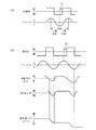
図2は制御弁17の開閉時期などを示すタイムチャートであり、(A)は機関の定常運転時つまり燃料蓄圧部6へ高圧燃料を供給する燃料供給時、(B)は機関の減速運転時つまり燃料蓄圧部6の減圧時の動作を示している。また、図3は、高圧室側の燃圧が最も高い高燃圧時と高圧室側の燃圧が最も低い低燃圧時に第2逆止弁22へ作用する荷重を示している。
FIG. 2 is a time chart showing the opening / closing timing of the
燃料供給時には、図2(A)に示すように、プランジャ14が作動室13側へ上昇する上昇行程つまり作動室13の昇圧時に制御弁17を閉じる。これによって、プランジャ14の上昇に応じて作動室13内が昇圧され、作動室13内の開弁方向の荷重が閉弁方向の荷重(高圧室側の荷重と第1スプリング16の荷重との和)を上回ると、第1逆止弁15が開弁し、作動室13内の高圧燃料が高圧通路5の高圧室12側へ供給される。また、図2の符号31に示すように上昇行程内で制御部20の閉時期を調整することで、燃料供給量を適宜調整することができる。
At the time of fuel supply, as shown in FIG. 2A, the
ここで図3の符号32,33に示すように、第2逆止弁22を閉弁方向へ付勢する第2スプリング25のバネ力によるスプリング荷重(セット荷重)は、高燃圧時と低燃圧時とにかかわらず、開弁方向の荷重、つまりは高圧室側から受ける荷重(厳密にはバイパス通路21からの荷重と低圧室11からの荷重との和)と、この燃料供給時に作動室13に作用する最大負圧時の荷重と、の和よりも十分に大きく設定されている(符号32,33参照)。従って、燃料供給時に第2逆止弁22は閉弁状態に維持され、不用意に開くことはない。
Here, as indicated by
減圧時には、図2(B)に示すように、プランジャ14の下降行程つまり作動室減圧時に制御弁17を閉じる。これによって、プランジャ14の下降に伴って作動室13内の圧力が低下して負圧が強くなり、図3に示すように、第2逆止弁22の閉弁方向の荷重(第2スプリング25のスプリング荷重)に対し、作動室13内の負圧による荷重(減圧時の最大負圧時荷重)を加味した開弁方向の荷重が大きく上回る形となり、第2逆止弁22を確実に開弁させることができる。ここで、作動室13内の負圧の強化により第1逆止弁15は閉弁状態に確実に維持される。このように第2逆止弁22が開くことで、高圧通路5から低圧通路4へ燃料が戻されて、燃料蓄圧部6の圧力が減圧される。また、制御弁17の閉時期を調整することで、燃料の戻し量、すなわち減圧の度合いを適宜調整することができる(符号34参照)。
At the time of depressurization, as shown in FIG. 2B, the
このように本実施例によれば、燃料供給時にはプランジャ14の上昇行程で閉じられる既存の制御弁17を利用し、減圧時にはプランジャ14の下降行程で制御弁17を閉じることで、作動室13内の負圧を強めて第2逆止弁22を開弁させ、作動室13を介することなくバイパス通路21を通して高圧室12側から低圧室11側、つまり燃料蓄圧部6から燃料ポンプ3側へ燃料を戻すことができる。上述した従来例のように追加のアクチュエータ等を必要とせず、既存の制御弁17の他、高圧通路5や低圧通路4を戻り通路として利用しているために、構造が簡素化されるとともに、大幅な小型化・軽量化及び制御系の簡素化などを図ることができる。
As described above, according to this embodiment, the existing
また、第2逆止弁22は、作動室13に面する大径部23の裏面側の受圧面積が、高圧通路5に連通するバイパス通路21に面する第2逆止弁22のニードル弁24の受圧面積よりも遥かに大きく設定されている。このため、作動室13内の圧力(負圧)を第2逆止弁22に大きく作用させることができ、減圧時に高圧通路5側の圧力にかかわらず安定して第2逆止弁22を開弁させることができる。
Further, the
図4は本発明の第2実施例に係る内燃機関の燃料供給装置を示している。なお、上記第1実施例と同様の構成には同じ参照符号を付して重複する説明を適宜省略し、第1実施例と異なる部分について主に説明する。この第2実施例においては、制御弁17Aの開弁方向先端部35と第2逆止弁22Aの大径部23の閉弁方向基端部36との間に、第2逆止弁22Aを閉弁方向(図4の右方向)へ付勢する第2スプリング25Aを同軸上に圧縮状態で介装している。この第2実施例によれば、図5にも示すように、燃料供給時には、制御弁17が開弁方向(図4の右方向)へリフトすると、そのバルブリフトの分、第2スプリング25A及び第2逆止弁22Aがその閉弁方向(図4の右方向)へ押し出され、第2スプリング25Aのセット荷重が増加する形となり、第2逆止弁22Aを更に安定して確実に閉弁状態に維持することができる。一方、減圧時には、制御弁17Aが閉じている状態、つまり第2スプリング25A及び第2逆止弁22Aが最も開弁方向(図4の左方向)に位置している状態で、この第2逆止弁22Aが開くこととなるので、上述したバルブリフトによるセット荷重が作用することはなく、第2逆止弁22Aの開弁動作に悪影響を及ぼすことはない。
FIG. 4 shows a fuel supply apparatus for an internal combustion engine according to the second embodiment of the present invention. The same components as those in the first embodiment are denoted by the same reference numerals, and redundant description will be omitted as appropriate, and differences from the first embodiment will be mainly described. In the second embodiment, the
1…燃料供給装置
4…低圧通路
5…高圧通路
6…燃料蓄圧部
13…作動室
14…プランジャ
15…第1逆止弁
17,17A…制御弁
20…制御部
21…バイパス通路
22,22A…第2逆止弁
25,25A…第2スプリング(付勢部材)
DESCRIPTION OF
Claims (5)
上記高圧通路と作動室との間に設けられ、上記高圧通路から作動室への燃料の逆流を防止する第1逆止弁と、
上記低圧通路と作動室との連通・遮断を切り換える制御弁と、
この制御弁の動作を制御する制御部と、を有する内燃機関の燃料供給装置において、
上記高圧通路から低圧通路へ燃料を戻すバイパス通路と、
上記作動室内の圧力に応じて上記バイパス通路を開閉する第2逆止弁と、
を有することを特徴とする内燃機関の燃料供給装置。 A plunger for pressurizing a working chamber provided between the low pressure passage and the high pressure passage;
A first check valve provided between the high pressure passage and the working chamber to prevent a back flow of fuel from the high pressure passage to the working chamber;
A control valve for switching communication / blocking between the low pressure passage and the working chamber;
In a fuel supply device for an internal combustion engine having a control unit that controls the operation of the control valve,
A bypass passage for returning fuel from the high pressure passage to the low pressure passage;
A second check valve that opens and closes the bypass passage according to the pressure in the working chamber;
A fuel supply device for an internal combustion engine, comprising:
Priority Applications (1)
| Application Number | Priority Date | Filing Date | Title |
|---|---|---|---|
| JP2007338603A JP4924413B2 (en) | 2007-12-28 | 2007-12-28 | Fuel supply device for internal combustion engine |
Applications Claiming Priority (1)
| Application Number | Priority Date | Filing Date | Title |
|---|---|---|---|
| JP2007338603A JP4924413B2 (en) | 2007-12-28 | 2007-12-28 | Fuel supply device for internal combustion engine |
Publications (2)
| Publication Number | Publication Date |
|---|---|
| JP2009156238A JP2009156238A (en) | 2009-07-16 |
| JP4924413B2 true JP4924413B2 (en) | 2012-04-25 |
Family
ID=40960496
Family Applications (1)
| Application Number | Title | Priority Date | Filing Date |
|---|---|---|---|
| JP2007338603A Expired - Fee Related JP4924413B2 (en) | 2007-12-28 | 2007-12-28 | Fuel supply device for internal combustion engine |
Country Status (1)
| Country | Link |
|---|---|
| JP (1) | JP4924413B2 (en) |
Family Cites Families (5)
| Publication number | Priority date | Publication date | Assignee | Title |
|---|---|---|---|---|
| JPH10318060A (en) * | 1997-05-22 | 1998-12-02 | Toyota Motor Corp | Pressure accumulation type fuel injection device |
| DE19746490A1 (en) * | 1997-10-22 | 1999-04-29 | Bosch Gmbh Robert | Dual fluid injection system for IC engine |
| JP2000136763A (en) * | 1998-11-04 | 2000-05-16 | Unisia Jecs Corp | Fuel injection control device |
| JP3786002B2 (en) * | 2001-12-14 | 2006-06-14 | トヨタ自動車株式会社 | High pressure fuel supply device for internal combustion engine |
| JP3944413B2 (en) * | 2002-05-24 | 2007-07-11 | 株式会社日立製作所 | High pressure fuel supply pump |
-
2007
- 2007-12-28 JP JP2007338603A patent/JP4924413B2/en not_active Expired - Fee Related
Also Published As
| Publication number | Publication date |
|---|---|
| JP2009156238A (en) | 2009-07-16 |
Similar Documents
| Publication | Publication Date | Title |
|---|---|---|
| EP2055929A2 (en) | High-pressure liquid supply pump | |
| CN1241240A (en) | Fuel injection valve | |
| JP2005524795A (en) | Fuel injection system | |
| JP2004218633A (en) | High pressure fuel pump | |
| EP1780401B1 (en) | Fuel injection device | |
| US20080265054A1 (en) | Injector With A Pressure Intensifier That Can Be Switched On | |
| US7182070B2 (en) | Method and device for shaping the injection pressure in a fuel injector | |
| JP4662292B2 (en) | Fuel injection device | |
| JP4134979B2 (en) | Fuel injection device for internal combustion engine | |
| US8161947B2 (en) | Pressure boosting system for at least one fuel injector | |
| JP4924413B2 (en) | Fuel supply device for internal combustion engine | |
| JP2010071266A (en) | High-pressure fuel supply system | |
| US6871636B2 (en) | Fuel-injection device for internal combustion engines | |
| JP4519143B2 (en) | Injector | |
| JP2006233853A (en) | Injector | |
| JP3797133B2 (en) | Engine fuel injector | |
| JP4218630B2 (en) | Fuel injection device for internal combustion engine | |
| JP2006505734A (en) | Fuel injection device with built-in pressure booster | |
| JP4415962B2 (en) | Injector | |
| JP2005076510A (en) | Fuel injection device and control device therefor | |
| JP4458118B2 (en) | Fuel injection device | |
| US6419164B1 (en) | Fuel injection valve for internal combustion engines | |
| JP4407590B2 (en) | Fuel injection device for internal combustion engine | |
| JP4364864B2 (en) | Variable injection hole injector | |
| JP4400528B2 (en) | Fuel injection device for internal combustion engine |
Legal Events
| Date | Code | Title | Description |
|---|---|---|---|
| A621 | Written request for application examination |
Free format text: JAPANESE INTERMEDIATE CODE: A621 Effective date: 20101126 |
|
| A977 | Report on retrieval |
Free format text: JAPANESE INTERMEDIATE CODE: A971007 Effective date: 20111216 |
|
| TRDD | Decision of grant or rejection written | ||
| A01 | Written decision to grant a patent or to grant a registration (utility model) |
Free format text: JAPANESE INTERMEDIATE CODE: A01 Effective date: 20120110 |
|
| A01 | Written decision to grant a patent or to grant a registration (utility model) |
Free format text: JAPANESE INTERMEDIATE CODE: A01 |
|
| A61 | First payment of annual fees (during grant procedure) |
Free format text: JAPANESE INTERMEDIATE CODE: A61 Effective date: 20120123 |
|
| FPAY | Renewal fee payment (event date is renewal date of database) |
Free format text: PAYMENT UNTIL: 20150217 Year of fee payment: 3 |
|
| R150 | Certificate of patent or registration of utility model |
Free format text: JAPANESE INTERMEDIATE CODE: R150 |
|
| LAPS | Cancellation because of no payment of annual fees |