JP4907849B2 - Ink droplet ejection method and apparatus - Google Patents
Ink droplet ejection method and apparatus Download PDFInfo
- Publication number
- JP4907849B2 JP4907849B2 JP2004094631A JP2004094631A JP4907849B2 JP 4907849 B2 JP4907849 B2 JP 4907849B2 JP 2004094631 A JP2004094631 A JP 2004094631A JP 2004094631 A JP2004094631 A JP 2004094631A JP 4907849 B2 JP4907849 B2 JP 4907849B2
- Authority
- JP
- Japan
- Prior art keywords
- ejection
- waveform
- ink
- drive pulse
- dot information
- Prior art date
- Legal status (The legal status is an assumption and is not a legal conclusion. Google has not performed a legal analysis and makes no representation as to the accuracy of the status listed.)
- Expired - Fee Related
Links
Images


Classifications
-
- B—PERFORMING OPERATIONS; TRANSPORTING
- B41—PRINTING; LINING MACHINES; TYPEWRITERS; STAMPS
- B41J—TYPEWRITERS; SELECTIVE PRINTING MECHANISMS, i.e. MECHANISMS PRINTING OTHERWISE THAN FROM A FORME; CORRECTION OF TYPOGRAPHICAL ERRORS
- B41J2/00—Typewriters or selective printing mechanisms characterised by the printing or marking process for which they are designed
- B41J2/005—Typewriters or selective printing mechanisms characterised by the printing or marking process for which they are designed characterised by bringing liquid or particles selectively into contact with a printing material
- B41J2/01—Ink jet
- B41J2/015—Ink jet characterised by the jet generation process
- B41J2/04—Ink jet characterised by the jet generation process generating single droplets or particles on demand
- B41J2/045—Ink jet characterised by the jet generation process generating single droplets or particles on demand by pressure, e.g. electromechanical transducers
- B41J2/04501—Control methods or devices therefor, e.g. driver circuits, control circuits
- B41J2/04593—Dot-size modulation by changing the size of the drop
-
- B—PERFORMING OPERATIONS; TRANSPORTING
- B41—PRINTING; LINING MACHINES; TYPEWRITERS; STAMPS
- B41J—TYPEWRITERS; SELECTIVE PRINTING MECHANISMS, i.e. MECHANISMS PRINTING OTHERWISE THAN FROM A FORME; CORRECTION OF TYPOGRAPHICAL ERRORS
- B41J2/00—Typewriters or selective printing mechanisms characterised by the printing or marking process for which they are designed
- B41J2/005—Typewriters or selective printing mechanisms characterised by the printing or marking process for which they are designed characterised by bringing liquid or particles selectively into contact with a printing material
- B41J2/01—Ink jet
- B41J2/015—Ink jet characterised by the jet generation process
- B41J2/04—Ink jet characterised by the jet generation process generating single droplets or particles on demand
- B41J2/045—Ink jet characterised by the jet generation process generating single droplets or particles on demand by pressure, e.g. electromechanical transducers
- B41J2/04501—Control methods or devices therefor, e.g. driver circuits, control circuits
- B41J2/04573—Timing; Delays
-
- B—PERFORMING OPERATIONS; TRANSPORTING
- B41—PRINTING; LINING MACHINES; TYPEWRITERS; STAMPS
- B41J—TYPEWRITERS; SELECTIVE PRINTING MECHANISMS, i.e. MECHANISMS PRINTING OTHERWISE THAN FROM A FORME; CORRECTION OF TYPOGRAPHICAL ERRORS
- B41J2/00—Typewriters or selective printing mechanisms characterised by the printing or marking process for which they are designed
- B41J2/005—Typewriters or selective printing mechanisms characterised by the printing or marking process for which they are designed characterised by bringing liquid or particles selectively into contact with a printing material
- B41J2/01—Ink jet
- B41J2/015—Ink jet characterised by the jet generation process
- B41J2/04—Ink jet characterised by the jet generation process generating single droplets or particles on demand
- B41J2/045—Ink jet characterised by the jet generation process generating single droplets or particles on demand by pressure, e.g. electromechanical transducers
- B41J2/04501—Control methods or devices therefor, e.g. driver circuits, control circuits
- B41J2/04581—Control methods or devices therefor, e.g. driver circuits, control circuits controlling heads based on piezoelectric elements
-
- B—PERFORMING OPERATIONS; TRANSPORTING
- B41—PRINTING; LINING MACHINES; TYPEWRITERS; STAMPS
- B41J—TYPEWRITERS; SELECTIVE PRINTING MECHANISMS, i.e. MECHANISMS PRINTING OTHERWISE THAN FROM A FORME; CORRECTION OF TYPOGRAPHICAL ERRORS
- B41J2/00—Typewriters or selective printing mechanisms characterised by the printing or marking process for which they are designed
- B41J2/005—Typewriters or selective printing mechanisms characterised by the printing or marking process for which they are designed characterised by bringing liquid or particles selectively into contact with a printing material
- B41J2/01—Ink jet
- B41J2/015—Ink jet characterised by the jet generation process
- B41J2/04—Ink jet characterised by the jet generation process generating single droplets or particles on demand
- B41J2/045—Ink jet characterised by the jet generation process generating single droplets or particles on demand by pressure, e.g. electromechanical transducers
- B41J2/04501—Control methods or devices therefor, e.g. driver circuits, control circuits
- B41J2/04588—Control methods or devices therefor, e.g. driver circuits, control circuits using a specific waveform
-
- B—PERFORMING OPERATIONS; TRANSPORTING
- B41—PRINTING; LINING MACHINES; TYPEWRITERS; STAMPS
- B41J—TYPEWRITERS; SELECTIVE PRINTING MECHANISMS, i.e. MECHANISMS PRINTING OTHERWISE THAN FROM A FORME; CORRECTION OF TYPOGRAPHICAL ERRORS
- B41J2/00—Typewriters or selective printing mechanisms characterised by the printing or marking process for which they are designed
- B41J2/005—Typewriters or selective printing mechanisms characterised by the printing or marking process for which they are designed characterised by bringing liquid or particles selectively into contact with a printing material
- B41J2/01—Ink jet
- B41J2/135—Nozzles
- B41J2/14—Structure thereof only for on-demand ink jet heads
- B41J2/14201—Structure of print heads with piezoelectric elements
- B41J2/14209—Structure of print heads with piezoelectric elements of finger type, chamber walls consisting integrally of piezoelectric material
-
- B—PERFORMING OPERATIONS; TRANSPORTING
- B41—PRINTING; LINING MACHINES; TYPEWRITERS; STAMPS
- B41J—TYPEWRITERS; SELECTIVE PRINTING MECHANISMS, i.e. MECHANISMS PRINTING OTHERWISE THAN FROM A FORME; CORRECTION OF TYPOGRAPHICAL ERRORS
- B41J29/00—Details of, or accessories for, typewriters or selective printing mechanisms not otherwise provided for
- B41J29/38—Drives, motors, controls or automatic cut-off devices for the entire printing mechanism
-
- B—PERFORMING OPERATIONS; TRANSPORTING
- B41—PRINTING; LINING MACHINES; TYPEWRITERS; STAMPS
- B41J—TYPEWRITERS; SELECTIVE PRINTING MECHANISMS, i.e. MECHANISMS PRINTING OTHERWISE THAN FROM A FORME; CORRECTION OF TYPOGRAPHICAL ERRORS
- B41J2/00—Typewriters or selective printing mechanisms characterised by the printing or marking process for which they are designed
- B41J2/005—Typewriters or selective printing mechanisms characterised by the printing or marking process for which they are designed characterised by bringing liquid or particles selectively into contact with a printing material
- B41J2/01—Ink jet
- B41J2/135—Nozzles
- B41J2/14—Structure thereof only for on-demand ink jet heads
- B41J2/14201—Structure of print heads with piezoelectric elements
- B41J2/14209—Structure of print heads with piezoelectric elements of finger type, chamber walls consisting integrally of piezoelectric material
- B41J2002/14217—Multi layer finger type piezoelectric element
-
- B—PERFORMING OPERATIONS; TRANSPORTING
- B41—PRINTING; LINING MACHINES; TYPEWRITERS; STAMPS
- B41J—TYPEWRITERS; SELECTIVE PRINTING MECHANISMS, i.e. MECHANISMS PRINTING OTHERWISE THAN FROM A FORME; CORRECTION OF TYPOGRAPHICAL ERRORS
- B41J2/00—Typewriters or selective printing mechanisms characterised by the printing or marking process for which they are designed
- B41J2/005—Typewriters or selective printing mechanisms characterised by the printing or marking process for which they are designed characterised by bringing liquid or particles selectively into contact with a printing material
- B41J2/01—Ink jet
- B41J2/135—Nozzles
- B41J2/14—Structure thereof only for on-demand ink jet heads
- B41J2/14201—Structure of print heads with piezoelectric elements
- B41J2/14209—Structure of print heads with piezoelectric elements of finger type, chamber walls consisting integrally of piezoelectric material
- B41J2002/14225—Finger type piezoelectric element on only one side of the chamber
-
- B—PERFORMING OPERATIONS; TRANSPORTING
- B41—PRINTING; LINING MACHINES; TYPEWRITERS; STAMPS
- B41J—TYPEWRITERS; SELECTIVE PRINTING MECHANISMS, i.e. MECHANISMS PRINTING OTHERWISE THAN FROM A FORME; CORRECTION OF TYPOGRAPHICAL ERRORS
- B41J2/00—Typewriters or selective printing mechanisms characterised by the printing or marking process for which they are designed
- B41J2/005—Typewriters or selective printing mechanisms characterised by the printing or marking process for which they are designed characterised by bringing liquid or particles selectively into contact with a printing material
- B41J2/01—Ink jet
- B41J2/135—Nozzles
- B41J2/14—Structure thereof only for on-demand ink jet heads
- B41J2/14201—Structure of print heads with piezoelectric elements
- B41J2002/14306—Flow passage between manifold and chamber
-
- B—PERFORMING OPERATIONS; TRANSPORTING
- B41—PRINTING; LINING MACHINES; TYPEWRITERS; STAMPS
- B41J—TYPEWRITERS; SELECTIVE PRINTING MECHANISMS, i.e. MECHANISMS PRINTING OTHERWISE THAN FROM A FORME; CORRECTION OF TYPOGRAPHICAL ERRORS
- B41J2/00—Typewriters or selective printing mechanisms characterised by the printing or marking process for which they are designed
- B41J2/005—Typewriters or selective printing mechanisms characterised by the printing or marking process for which they are designed characterised by bringing liquid or particles selectively into contact with a printing material
- B41J2/01—Ink jet
- B41J2/135—Nozzles
- B41J2/14—Structure thereof only for on-demand ink jet heads
- B41J2002/14419—Manifold
Landscapes
- Particle Formation And Scattering Control In Inkjet Printers (AREA)
- Ink Jet (AREA)
Description
本発明は、インクジェット方式によるインク滴吐出方法及びその装置に関するものである。 The present invention relates to an ink droplet ejection method and apparatus using an inkjet method.
最近の先行技術のオンディマンド型のインクジェット式の記録ヘッドにおいては、特許文献1等に開示されているように、キャビティユニットに、複数個のノズルとそれに対応するキャビティ(インクチャンネル、圧力室)を列状(ほぼ直線状)に備え、各圧力室にインクを供給するように構成する一方、キャビティユニットの背面側には、圧電セラミックス板(圧電シート)を挟んでコモン電極と個別電極とを交互に積層して構成された圧電アクチュエータであって、その圧電シートの積層方向に対向する前記個別電極とコモン電極との間の圧電シートの部分である活性部が圧力室の上方にて平面視で重なるように接合された構成が開示されている。この構成によれば、圧電アクチュエータの各活性部に電圧印加することで、その活性部が変形し、対応する圧力室の容積が減少すると、そのキャビティ内のインクがノズルから吐出されて、被記録媒体にインクドットとして記録できるようにしていた。この記録ヘッドは、被記録媒体の搬送方向(副走査方向)と直交する方向(主走査方向、用紙の幅方向))に沿って往復移動可能に構成されており、例えば、75個のノズルが1インチの長さの間に一定ピッチで配置されたノズル列の延びる方向は被記録媒体の搬送方向(副走査方向)と平行状である。
In a recent prior art on-demand type ink jet recording head, as disclosed in
そして、その記録ヘッドの駆動装置として、主走査方向に沿って順次形成すべきドット情報に基づき、予め定められた吐出周期において、選択的に駆動波形(駆動パルス信号)を出力することによりキャビティ(圧力室)内のインクを被記録媒体(用紙)に向かって吐出する。 As a drive device for the recording head, a cavity (drive pulse signal) is selectively output in a predetermined discharge cycle based on dot information to be sequentially formed along the main scanning direction. The ink in the pressure chamber is discharged toward the recording medium (paper).
ところで、特許文献1でも指摘されているように、インク滴の吐出の際に、その液滴以外にサテライトと呼ばれる余分な液滴が発生することがある。これは、複数の液滴で1つのインクドットを形成するために連続して吐出した後など、主となる液滴の吐出後も圧力室内の圧力変動が十分納まらず、残存圧力によってインクが飛び出してしまうのが主な原因である。サテライトが発生すると、記録の仕上がりが本来のそれからかけ離れたものとなってしまう。特に、現在形成しているインクドットがインク液滴量が大きい場合のサテライトのインク液滴量も比例的に大きくなるから、その次に、同じノズルによってインクドットを形成しない場合には、サテライトがこのインクドット位置に飛散すると、目立つので深刻である。また、サテライトが形成されなくても、圧力変動により次のインクドット形成が不安定になることがある。
By the way, as pointed out in
そこで、従来よりサテライトの発生を防いだり、不安定な吐出を防ぐために駆動波形にキャンセルパルスを挿入することが行なわれたり、特許文献1にて提案したように、隣接する2つの吐出周期のうち、現在(今回)の吐出周期のドット情報が吐出であり、次(次回)の吐出周期のドット情報が不吐出であるときには、現在(今回)の吐出周期から次(次回)の吐出周期にまたがる駆動波形(駆動パルス信号)を出力させていた。
Therefore, conventionally, the generation of satellites is prevented, a cancel pulse is inserted into the drive waveform in order to prevent unstable discharge, or as proposed in
次に、特許文献1に開示の駆動波形の態様について、図13を参照しながら説明する。主走査方向のインクドット位置の番号をカラム番号とするとき、その隣接する3つのカラムをn番、n+1番、n+2とする。
Next, the mode of the drive waveform disclosed in
今、No. 0のノズルに対して、n番カラムには、インク滴が吐出されるようなドット情報があり、n+1番カラムには、ドット無し、つまり不吐出のドット情報があるとする。予め定められた吐出周期Toは一定とする。その場合、図12に示すようなヘッドドライバ100を使用していた。即ち、ヘッドドライバ100内には、シフトレジスタ101、ラッチ回路102、マルチプレクサ103、ドライバ104が構成されている。そして、マルチプレクサ103及びドライバ104は、ノズルNo. 0〜74までのそれぞれに対応して直列に接続されている。
For the No. 0 nozzle, it is assumed that the nth column has dot information for ejecting ink droplets and the n + 1th column has no dot, that is, non-ejection dot information. The predetermined discharge period To is constant. In that case, the
コンピュータ等の外部装置から印字データであるドット情報[記録ヘッドが主走査方向に1回移動する間に形成すべきドット情報(印字データ)]がイメージメモリ106に送られる。図示しないゲートアレイ回路内に構成された指定信号選択回路107は、イメージメモリ106に格納された印字データ(ドット情報)を順次読み出し、後述するようにそのドット情報とROM内のデータ、ロング波形選択信号に基づいて、波形信号の種類を指定する指定信号を発生し、シリアルに出力する。なお、説明を簡単にするため、指定信号は2bitの信号で、後述する4種類の駆動波形から1つを選択するものとする。シリアルに出力された指定信号は、シフトレジスタ101に入力され、1つの記録ヘッドのノズル数に対応するパラレルデータに変換され、さらに、パラレルデータに変換された指定信号は、ラッチ回路(フリップフロップ)102にラッチされ、ストローブ信号に同期してマルチプレクサ103に出力される。
Dot information that is print data [dot information to be formed while the recording head moves once in the main scanning direction (print data)] is sent to the
この一方でマルチプレクサ103には波形発生回路105から3種類の波形(「波形1」、「L波形2」、「L波形3」)が入力され、これにVDD1の定電圧を加えた計4種類の波形が入力されている。波形発生回路105は、「波形1」、「L波形2」、「L波形3」の3種類の波形を発生させるものであり、このうち、「波形1」は所定の吐出周期To内に納まる複数個のパルスを有して指定の1つのインクドットを形成する波形となっている。「L波形2」、「L波形3」は、隣接する吐出周期(To×2)にまたがって出力される波形で、複数のインク滴を連続して形成する複数の吐出パルスのみの波形であってもよいが、キャビティ内の圧力変動を抑えるキャンセルパルスを、吐出パルス列の末尾または中間に有する波形しても良い。
On the other hand, the
ところで、波形発生回路105からノズルの数に対応する全数のマルチプレクサ103に対して、「波形1」、「L波形2」、「L波形3」の3種類の駆動波形を同時に並列的に供給するように信号線が接続されている。このため、仮に、前述したように、No. 0のノズルに対して、n番カラムには、インク滴が吐出されるようなドット情報があり、n+1番カラムには、不吐出のドット情報がある一方、隣り合うNo. 1のノズルに対しては、n+1番カラムには、インク滴が吐出されるようなドット情報があり、n+2番カラムには、不吐出のドット情報があるとするとき、No. 0のノズルに対して、n番カラムに相当する吐出周期箇所にて「波形2」の始め部分を出力すると、その「波形2」の後端部分はn+1番カラムに相当する吐出周期にまたがっている。そのとき、No. 1のノズルに対しては、n+1番カラムに相当する吐出周期に同じ「L波形2」を出力すると、No. 0のノズルにおけるn+1番カラムに相当する吐出周期の波形(「L波形2」の後端部分)が、前記「L波形2」の始め部分に置き換わってしまい、正規の「L波形2」が出力できなくなる。
By the way, three types of driving waveforms “
その不都合を解消するため、特許文献1の構成では、「L波形2」と「L波形3」とは、パルス列の内容は同一であるが、ストローブ信号の1吐出周期だけずれて出力される。ロング波形選択信号は、Low 電圧とHigh電圧を吐出周期毎に交互に繰り返す波形で、ROMのプログラムに基づいてCPUが指定信号選択回路107に出力する。
In order to eliminate this inconvenience, in the configuration of
また、ROMには、ロング波形選択信号と、前回(n番カラム)のインクドット、今回(n+1番カラム)のインクドット及び次回(n+2番カラム)のインクドットに対応する各ドット情報に基づいて、現在のインクドットにおいて使用する駆動波形を選択するテーブルが格納されている。指定信号発生回路65は、イメージメモリから読み出した(n番カラム)〜(n+2番カラム)のインクドットの各ドット情報を記憶し、ROMのテーブルおよびロング波形選択信号を参照して、所定のカラムにおいて使用する駆動波形の種類を指定する信号(0、1、2、3)を出力するものである。
Further, the ROM has a long waveform selection signal and dot information corresponding to the previous (nth column) ink dot, the current (n + 1 column) ink dot, and the next (n + 2 column) ink dot. A table for selecting a driving waveform to be used in the current ink dot is stored. The designation
このように、特許文献1では、ロング波形選択信号を指定信号選択回路107に入力することにより、「L波形2」と「L波形3」とが隣接するタイミングで交互にシフトレジスタ101に出力させることで、隣接する2つの吐出周期(To×2)にまたがる駆動波形(駆動パルス信号)である「L波形2」及び「L波形3」を確実にドライバ104にて出力できるようにしたものである。
しかしながら、特許文献1の構成によれば、上記のように、隣接する2つの吐出周期にまたがる駆動波形(駆動パルス信号)を発生させるための波形発生回路105が複雑になる。即ち、1つの駆動波形が有するパルス信号数が増大するため、そのパルス発生回路の構造が複雑になるし、波形発生回路105で、上述のように同じ波形の「波形2」及び「波形3」を別々に記憶させておかなければならないから、その記憶容量も大きいものを準備しておかなければならず、ヘッドの駆動装置の製造コストが高くなるという問題があった。
However, according to the configuration of
本発明は上記のような課題を解決するためになされたものであり、1つの吐出周期に納まる複数種類の駆動パルス信号のみを出力することにより、サテライトが発生せず、且つコストも低減できるインク滴吐出方法及びその装置を提供することを目的とする。 The present invention has been made to solve the above-described problems. By outputting only a plurality of types of drive pulse signals that fall within one ejection cycle, no satellite is generated and the cost can be reduced. An object of the present invention is to provide a droplet discharge method and an apparatus therefor.
前記目的を達成するため、請求項1に記載の発明のインク滴吐出装置は、被記録媒体に対してインク滴を吐出するノズルとそのノズル毎に対応する圧力室と、インクが充填された前記圧力室毎の容積を変化させるためのアクチュエータと、被記録媒体との相対移動方向に沿って順次形成すべきドット情報に基づいて、前記圧力室の容積を変化させてインク滴を前記ノズルから吐出させるべく、所定の吐出周期において前記アクチュエータに対して選択された駆動パルス信号を出力する制御装置とを備えたインク滴吐出装置において、前記制御装置は、各吐出周期内に納まる複数種類の駆動パルス信号を発生させるためのパルス波形発生手段と、隣接する2つの吐出周期のドット情報に基づいて前記複数種類の駆動パルス信号のうちから、各吐出周期ごとに1種類の駆動パルス信号を選択する信号波形選択手段と、選択された駆動パルス信号を出力する出力手段とを備え、前記信号波形選択手段は、隣接する2つの吐出周期のうち今回の吐出周期におけるドット情報が、インク滴の吐出液滴量が最も多いものであって、次回の吐出周期におけるドット情報がインク不吐出である第1の場合には、今回の吐出周期におけるドット情報がインク滴の吐出液滴量の最も多いものであって、次回の吐出周期におけるドット情報がインク吐出である第2の場合と、少なくとも、前記今回のための駆動パルス信号が異なるように前記今回及び次回のための駆動パルス信号を不吐出に対応する駆動パルス信号を除く前記複数の駆動パルス信号の内から2種類選択し、前記出力手段では、前記第1の場合における選択された駆動パルス信号は、前記今回及び次回の吐出周期内に出力される前記2種類の駆動パルス信号を組み合わせて波形が作られ、且つ前記今回及び次回の吐出周期内にそれぞれ駆動パルス信号を出力することを特徴とするものである。
以上
In order to achieve the above object, an ink droplet ejection apparatus according to
more than
請求項2に記載の発明は、請求項1に記載のインク吐出装置において、前記選択された2種類の駆動パルス信号を前記今回及び次回の吐出周期にわたって連続状に出力するものである。
The invention according to
請求項3に記載の発明は、請求項1または2に記載のインク滴吐出装置において、前記第1の場合に前記今回のために選択された駆動パルス信号は、前記第2の場合に前記今回のために選択される駆動パルス信号よりも吐出パルスの数が少ないように設定され、前記第1の場合に前記次回のために選択された駆動パルス信号は、前記吐出パルスを含むものである。 According to a third aspect of the present invention, in the ink droplet ejection apparatus according to the first or second aspect , the drive pulse signal selected for the current time in the first case is the current time in the second case. Therefore, the number of ejection pulses is set to be smaller than that of the drive pulse signal selected for the above-mentioned operation, and the drive pulse signal selected for the next time in the first case includes the ejection pulse.
請求項4に記載の発明は、請求項1乃至3のいずれかに記載のインク滴吐出装置において、前記第1の場合において、前記次回の吐出周期における選択された駆動パルス信号は、インク滴の吐出液滴量が少ないドット情報に対応する駆動パルス信号と同じものである。
According to a fourth aspect of the present invention, in the ink droplet ejection apparatus according to any one of the first to third aspects, in the first case, the selected drive pulse signal in the next ejection cycle is an ink droplet This is the same as the drive pulse signal corresponding to dot information with a small amount of ejected droplets.
請求項5に記載の発明は、請求項1乃至4のいずれかに記載のインク滴吐出装置において、前記第1の場合において、前記次回の吐出周期に選択された駆動パルス信号は、前記圧力室に対する圧力変動を低減させるキャンセルパルスを含むものである。
According to a fifth aspect of the present invention, in the ink droplet ejection device according to any one of the first to fourth aspects, in the first case, the drive pulse signal selected for the next ejection cycle is the pressure chamber. A cancel pulse for reducing the pressure fluctuation with respect to is included.
請求項6に記載の発明は、請求項1乃至5のいずれかに記載のインク滴吐出装置において、前記駆動パルス信号における各パルスのパルス幅を変えることにより、吐出される液滴量を変えるものである。 According to a sixth aspect of the invention, in the ink droplet ejection device according to any one of the first to fifth aspects, the amount of ejected droplets is changed by changing the pulse width of each pulse in the drive pulse signal. It is.
請求項1に記載の発明によれば、従来のロング波形は、2つの吐出周期に跨がったパルス列であるから必然的に1つの波形中に含まれるパルス数が増大し、しかも、あるノズルにロング波形を出力した1吐出周期後に別のノズルにロング波形を出力するために、同じ波形のロング波形を別々に記憶させねばならず、それに応じて、記憶(メモリ)容量の大きい波形発生回路を準備しなければならないが、本発明によれば、1つの駆動パルス信号は1つの吐出周期内に収まるものであって、そのような2つ駆動パルス信号を組み合わせてロング波形を作るから、必然的に1つの波形中に含まれるパルス数は少なくなる。従って、本発明によれば波形発生回路における記憶容量も少なくでき、コストを低減できるという効果を奏する。 According to the first aspect of the present invention, since the conventional long waveform is a pulse train extending over two ejection cycles, the number of pulses included in one waveform inevitably increases, and a certain nozzle In order to output a long waveform to another nozzle after one discharge cycle when a long waveform is output to the same, the long waveform of the same waveform must be stored separately, and accordingly, a waveform generating circuit with a large storage (memory) capacity However, according to the present invention, one drive pulse signal is contained within one ejection cycle, and such two drive pulse signals are combined to form a long waveform. Therefore, the number of pulses included in one waveform is reduced. Therefore, according to the present invention, the storage capacity in the waveform generation circuit can be reduced, and the cost can be reduced.
請求項2に記載の発明によれば、予め選択すべき駆動パルス信号は複数個のパルスの連続(パルス列)からなり、各パルスのパルス幅や隣接するパルス間の区間長さ(パルス間隔)が異なるものを複数種類準備してこれらを組合わせて所定の駆動パルス信号を作るものである。従って、2つの隣接する吐出周期を観察すれば、従来の隣接する2つの吐出周期にまたがってロング波形を出力したものと全く同じパルス列となり、サテライトの発生防止を確実に行える。 According to the second aspect of the present invention, the drive pulse signal to be selected in advance is composed of a series of pulses (pulse train), and the pulse width of each pulse and the section length (pulse interval) between adjacent pulses are set. A plurality of different types are prepared and combined to create a predetermined drive pulse signal. Therefore, if two adjacent ejection cycles are observed, the pulse train is exactly the same as that in the conventional case where a long waveform is output across two adjacent ejection cycles, so that satellite generation can be reliably prevented.
請求項3に記載の発明によれば、吐出液滴量を最も多くするために必要な複数の吐出パルスを連続する2つの吐出周期の期間ないに分散させることができるので、インクの吐出を安定させることができる。 According to the third aspect of the present invention, since a plurality of ejection pulses necessary for maximizing the amount of ejected droplets can be dispersed within two consecutive ejection periods, ink ejection is stable. Can be made.
請求項4に記載の発明によれば、インク滴の吐出液滴量が少ないドット情報を流用することができ、波形発生回路における記憶容量も格段に少なくでき、コストを一層低減できるという効果を奏する。 According to the fourth aspect of the present invention, dot information with a small amount of ejected ink droplets can be used, the storage capacity in the waveform generation circuit can be remarkably reduced, and the cost can be further reduced. .
請求項5に記載の発明によれば、次回の吐出周期における選択された駆動パルス信号中にキャンセルパルスを含むので、サテライト発生をより効果的に防止することができる。 According to the fifth aspect of the present invention, since the cancel pulse is included in the selected drive pulse signal in the next ejection cycle, satellite generation can be more effectively prevented.
請求項6に記載の発明によれば、前記駆動パルス信号における各パルスのパルス幅を変えることにより、吐出される液滴量を変えるものであるから、インクの吐出液滴量の大小の制御を簡単な回路で達成させることができ、コストを低減できるという効果を奏する。 According to the sixth aspect of the present invention, the amount of ejected droplets is changed by changing the pulse width of each pulse in the drive pulse signal. This can be achieved with a simple circuit, and the cost can be reduced.
次に、本発明を実施するための最良の形態について図面を参照しながら説明する。図1はインクジェットプリンタの概略平面図、図2は本発明の実施の形態による圧電式のインク滴吐出装置の記録ヘッド10におけるキャビティユニット11と圧電アクチュエータ12との斜視図、図3は図2の III−III 線矢視拡大断面図、図4は圧電アクチュエータの活性部を示す一部切欠き拡大断面図、図6は駆動装置のブロック図、図7はカラムとインクドットとの関係を示す図、図8は第1実施形態のパルス信号(波形)を示す図、図9は各カラムにおけるドット情報と選択される波形との関係を示す図、図10は第1実施形態のパルス信号(波形)を示すタイムチャート、図11は各カラムにおけるドット情報と選択される波形を実行するためのフローチャート、図12は従来の駆動波形の態様を示すタイムチャート、図13は従来の駆動装置(ドライバ)のブロック図である。
Next, the best mode for carrying out the present invention will be described with reference to the drawings. 1 is a schematic plan view of an ink jet printer, FIG. 2 is a perspective view of a
図1において、インクジェットプリンタ1は、後述するインクジェット式の記録ヘッド10を下面側に搭載したキャリッジ2がガイドレール3a,3bに摺動自在に支持されたものである。そして、キャリッジ2は、ガイドレール3a,3bと平行状に配置されたタイミングベルト4に連結されており、このタイミングベルト4に対するキャリッジモータ5の駆動により、キャリッジ2は主走査方向(図1のY方向)に沿って往復移動できるように構成されている。図示しない用紙等の被記録媒体はY方向と直交するX方向(副走査方向に搬送される。
In FIG. 1, an
本実施形態のインクジェットプリンタ1はフルカラー記録のために、ブラック(BK)、シアン(C)、マゼンタ(M)、イエロー(Y)の4色のインクを収容した4つのインクカートリッジ6a〜6dが本体ケースに横一列状に静置され、着脱可能に構成されている。そして、各インクカートリッジ6a〜6dとインクジェットの記録ヘッド10とをインク供給管7a〜7dを介してそれぞれ連結されてインクが供給される。なお、別の実施形態として、キャリッジ2に直接インクカートリッジ6a〜6dを搭載した構成であっても良い。
The
図2〜図4に示すように、記録ヘッド10は、金属板製の積層型のキャリッジユニット11と、その上面に対して接合されるプレート積層型の圧電アクチュエータ12とからなり、圧電アクチュエータ12の上面には、画像データ及びヘッドの駆動信号を伝送する外部機器との接続のために、可撓性を有するフラットケーブル13がハンダ接合されている。
As shown in FIGS. 2 to 4, the
前記キャビティユニット11は図2〜図4に示すように構成されている。すなわち、下層から順にノズルプレート14、カバープレート15、ダンパープレート16、二枚のマニホールドプレート17,18、3枚のスペーサプレート19,20,21及び圧力室23が形成されているベースプレート22の合計9枚の薄い板をそれぞれ接着剤にて重ね接合して積層した構成であり、実施形態では、合成樹脂製のノズルプレート14を除き、各プレート15〜22は、42%ニッケル合金鋼板製で、50μm〜150μm程度の厚さを有する。
The
ノズルプレート14には、微小径(実施形態では25μm程度)の多数のインク噴出用のノズル24が、当該ノズルプレート14における第1の方向(キャビティユニット11の長辺方向であり、図1、図2及び図3において、X方向)に沿ってなした列が4列千鳥配列状に設けられている。
The
即ち、キャビティユニット11を図1のY方向(短辺方向)に沿って切断し、且つ短辺の中央線Cより右側のみ示す図3において、右側位置の第1ノズル列24−1に属するノズル24と、中央線Cに近い側の第2ノズル列24−2に属するノズル24とは、ノズルプレート14の第1の方向に延びる2つの平行状の近接した基準線(図示せず)に沿って各々微小ピッチPの間隔で千鳥状配列にて多数個穿設されている。同様に、中央線Cより左側においても、第3ノズル列24−3と第4ノズル列24−4(但し、図3には図示せず)とにそれぞれ属するノズル24は、同じく第1の方向に延びる2つの平行状の近接した基準線に沿って、各々微小ピッチPの間隔で千鳥状配列にて多数個穿設されている。また、第1ノズル列24−1と第2ノズル列24−2との組と、第3ノズル列24−3と第4ノズル列24−4との組は、キャビティユニット11の短辺方向(第2の方向、図1において、Y方向)に間隔をおいて平行に配置されている。実施例では、第1列〜第4列の各々のノズル列の長さは1インチ、各々のノズル24の数は75個で、つまり配列密度は75(dpi[ドット・パー・インチ])である。
That is, nozzles belonging to the first nozzle row 24-1 at the right position in FIG. 3 where the
図2に示すキャビティユニット11の最上層であるベースプレート22における圧力室23が作る第1圧力室列23−1は第1ノズル列24−1と対応する。同様にして、第2圧力室列23−2は第2ノズル列24−2と、第3圧力室列23−3は第3ノズル列24−3と、第4圧力室列23−4は第4ノズル列24−4と、各々対応関係にある。
The first pressure chamber row 23-1 created by the
次に、キャビティユニット11の最上層であるベースプレート22における圧力室23の配置関係を、その上に配置する圧電アクチュエータ12における活性部の配置との関係から説明する。
Next, the arrangement relationship of the
1つの圧電アクチュエータ12には、各ノズル24に対応する圧力室23を作動させるように75個の活性部を有して配置される。そして、各圧電アクチュエータ12は、後に図4を参照して詳述するように、コモン電極37と、前記各圧力室23の位置毎に対応させて配置された個別電極36とが圧電シートを挟んで交互に積層され、任意の個別電極36とコモン電極37との間に電圧を印加することにより、その印加された個別電極36に対応した圧電シートの活性部に、当該積層方向に圧電縦効果による歪みが発生するものである。該活性部は、圧力室23の数と同一の数で同一の列にてその対応する位置に形成されている。
One
即ち、活性部は、ノズル24(圧力室23)の列方向(第1の方向)に沿って並べられ、且つノズル列の数(4つ)と同じ数だけ、第2の方向に並べられている。また、各活性部は、第2の方向(キャビティユニット11の幅方向、Y方向)に圧力室23の長手方向に長く形成され、且つ隣接する活性部の配置間隔(ピッチP)も圧力室23の配置と同様であって、千鳥状配列されることになる(図3参照)。
That is, the active portions are arranged along the row direction (first direction) of the nozzles 24 (pressure chambers 23), and are arranged in the second direction by the same number as the number of nozzle rows (four). Yes. Each active part is formed long in the longitudinal direction of the
各圧力室23は、ベースプレート22の幅方向(第2の方向)に長く、且つベースプレート22を厚さ方向に貫通して形成され、隣接する圧力室23間は隔壁70によって隔てられている。その各圧力室23の入口端は、スペーサプレート19、20、21に形成された第2インク通路30、絞り部28、第1インク通路29を介してマニホールド室26に連通する(図3参照)。
Each
また、各圧力室23の流出端は、ベースプレート22とノズルプレート14との間に位置するスペーサプレート19、20、21、マニホールドプレート17、18、ダンパープレート16及びカバープレート15に形成されたインク流通路としての各連通路25を介して各ノズル24に連通するが、この連通路25の一部は、ベースプレート22とノズルプレート14との間の積層されるプレート15〜21のうち少なくとも1枚(1層)のプレートにはその広幅面(表面または裏面)と略平行状の凹溝状流通路50を備えることにより、隣接する2つのノズル列に対応する2つのマニホールド室26の間に連通路25が形成できるようにしている(図3参照)。
Further, the outflow end of each
一方、各圧電アクチュエータ12は、図4に示すように、1枚の厚さが30μm程度の圧電セラミックス板からなる複数枚(実施形態では7枚)の圧電シート33、34とが交互に積層された群と、この群の上面に2枚のシート46、47からなる拘束層を積層し、さらにその上面にトップシート35を積層した構造である。拘束層のシ−ト及びトップシ−トは圧電セラミックス板でも良いし、他の材料でも良く、電気的絶縁性を有すれば良い。
On the other hand, as shown in FIG. 4, each
最下層の圧電シート34から上方へ数えて奇数番目の圧電シート34の上面にはコモン電極37が配置され、偶数番目の圧電シート33の上面(広幅面)には、キャビティユニット11における各圧力室23に対応した箇所ごとに個別電極36が配置されている。この個別電極36とコモン電極37及びこれら両電極36、37により挟まれた圧電シート33、34により活性部が構成されている。個別電極37は、その平面視外形形状が対応する圧力室23とほぼ同じ形状を有し、第2の方向(短辺方向)に沿って各圧電シート33の短辺と平行に細長く形成されている。
A
この構成において、圧電アクチュエータ12における前記各個別用接続電極66及びコモン用接続電極を介して全個別電極36とコモン電極37との間に分極用の高電圧を印加することで、各個別電極36とコモン電極37との間に挟まれた圧電シート33、34の部分を分極処理する。これにより、各個別電極36とコモン電極37との間に挟まれた圧電シート33、34の部分を活性部とする。そして、任意の個別用接続電極66とコモン用接続電極とを介して個別電極36とコモン電極37との間に駆動電圧を印加して、対応する活性部の分極方向に電界を発生させると、その活性部が積層方向に伸長し、対応する圧力室23の内容積が縮小され、この圧力室23内のインクが、対応するノズル24から液滴状に吐出して、所定の印字が行われる。
In this configuration, by applying a high voltage for polarization between all the
カラー印刷する場合に、4色のインク(ブラック、シアン、イエロー、マゼンタ)を使用する時には、例えば、前記第1ノズル列吐出液滴量をブラックインクの吐出用とし、第2ノズル列24−2をシアンインク、第3ノズル列24−3をイエローインク、第4ノズル列24−4をマゼンタインクの吐出用にそれぞれ設定すると、対応するマニホールドプレート17(18)に形成された第1列目のマニホールド室26にはブラックインクが充填され、第2列目のマニホールド室26にはシアンインクが充填され、第3列目のマニホールド室26にはイエローインクが充填され、第4列目のマニホールド室26にはマゼンタインクが充填されるのである。
When four colors of ink (black, cyan, yellow, magenta) are used for color printing, for example, the first nozzle row discharge droplet amount is used for black ink discharge, and the second nozzle row 24-2 is used. Are set to discharge cyan ink, the third nozzle row 24-3 to discharge yellow ink, and the fourth nozzle row 24-4 to discharge magenta ink, respectively, the first row formed on the corresponding manifold plate 17 (18). The
次に個別電極36及びコモン電極37に印加する各種の駆動パルス信号(駆動波形)を圧電アクチュエータ12に印加するための駆動装置及びその態様について説明する。
Next, a drive device for applying various drive pulse signals (drive waveforms) to be applied to the
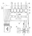
まず、本実施形態のインクジェット式プリンタの主要部の概略について、図5に示すブロック図を参照しながら説明すると、本インクジェット式プリンタ1は、印字データ処理等の記録動作の制御を行なうゲートアレイ回路G/A51、その他のプリンタ全体の制御を行なうCPU52、パーソナルコンピュータ等のコンピュータシステムPCと接続するためのインタフェースI/F53、コンピュータシステムPCから受信した印字データを格納するイメージメモリ54、CPUにそれぞれの駆動回路を介して接続されたキャリッジ移動用のCRモータ5、用紙搬送用のLFモータ55、キャリッジの原点センサ56、印字位置に用紙があるか否かを検出する給紙センサ57、キャリッジの位置を検出するためのキャリッジエンコーダ58、プリントやデータ通信など本インクジェット式プリンタで実行される様々なプログラムやそのプログラムで使用されるデータが格納されたROM59、そのプログラムの実行において一時的なデータ記憶を行なうRAM60、ヘッドドライバ61、Y・M・C・Kの4色分用意されたインクジェットヘッド及び電源(図示せず)等を備えている。
First, the outline of the main part of the ink jet printer according to the present embodiment will be described with reference to the block diagram shown in FIG. 5. The
この中で、ヘッドドライバ61の周辺について更に詳細に表したのが図6である。本図に示すようにヘッドドライバ61内には、シフトレジスタ62、ラッチ回路(フリップフロップ回路)63、マルチプレクサ64、ドライバ65が構成されている。各ドライバ65は、上記した圧電アクチュエータ12の各活性部に対応する個別電極36に接続されている。ゲートアレイ回路G/A51内に構成された指定信号選択回路67は、イメージメモリ54に格納された印字データ(ドット情報)を順次読み出し、後述するようにそのドット情報(階調情報を含む)とROM内のデータ(ドット情報とそれに関連する互いに隣接する複数の吐出周期、またはカラム番号のデータ、後に詳述する)に基づいて、波形信号の種類を指定する指定信号を発生し、シリアルに出力する。なお、本実施の形態では簡単のため、後述する予め設定された7種類の駆動波形(以下、単に、波形ということもある)から1つを選択する。シリアルに出力された指定信号は、シフトレジスタ62に入力され、1つのインクジェットヘッドのノズル孔数に対応するパラレルデータに変換され、さらに、パラレルデータに変換された指定信号は、ラッチ回路63にラッチされ、ストローブ信号に同期してマルチプレクサ64に出力される。この一方でマルチプレクサ64には波形発生回路68から5種類の駆動用の波形が入力され、これにVDD1の定電圧を加えた計6種類の波形が入力されている。適宜位置のカラムに対するこれら7種類の波形を図8に示す。
FIG. 6 shows the periphery of the
なお、以下に述べる波形1〜6は、すべて1吐出周期To内で複数のパルスを出力して指定の1つのカラムにインクドット(不吐出の場合も含む)を形成する波形となっている。従って、各パルスのパルス幅及びパルス間隔は、記録ヘッド10の構成(機械的特性)に応じて予め設定されるものである。
この複数のパルス(駆動パルス列)は、インク滴を吐出させる吐出パルスDと、キャビティ内の圧力変動を抑えるキャンセルパルスCとの組み合わせであり、駆動パルス列の最初には吐出パルスDが配列され、キャンセルパルスCは吐出パルス列の末尾または中間に有する。 The plurality of pulses (driving pulse train) is a combination of an ejection pulse D that ejects ink droplets and a cancel pulse C that suppresses pressure fluctuations in the cavity. The pulse C is at the end or middle of the ejection pulse train.
図7は、カラムの番号とノズル列から吐出されるインクドットとの関係を模式的に表した図であり、例えば、前記実施形態において、例えば、記録ヘッド10におけるブラックのインクを吐出する第1ノズル列24−1によりインクドット(インク滴による画像)が形成されて行く様子を説明すると、1つのノズル列に75個のノズルを有する場合、その順番No. 0ノズル、No. 1ノズル、No. 2ノズル、‥‥…、No. 74ノズルのノズル列は副走査方向(X方向)に一直線に並列されており、この記録ヘッド10を搭載したキャリッジ2が副走査方向(X方向)と直交する主走査方向(Y方向)に沿って往復移動されることにより用紙上に、インクドットが形成される。そのY方向のインクドットの位置をカラムといい、図7ではY方向に沿って左側のカラム番号(nは任意の整数値であって、被記録媒体の主走査方向の幅寸法に応じて記録できる範囲内に展開されるドット情報の数に対応する)が小さく右方向に行くにつれて順に大きくなる。図7においてn番のカラムで、第1ノズル列24−1のノズル24により第1回目のインク滴の吐出があった場合、記録ヘッド2が左に1ピッチだけ移動した位置で、同じく第1ノズル列24−1のノズル24により第2回目インク滴の吐出があった位置がn+1番カラムとなる。さらに別の表現によれば、n番のカラムに第1ノズル列24−1のノズル24によりインクドット(不吐出の場合を含む)が形成されるときを今回の吐出周期Toとすると、その今回の吐出周期Toよりも1吐出周期Toだけ前に、同じく第1ノズル列24−1のノズル24によりインクドット(不吐出の場合を含む)が形成される位置がn−1番のカラムとなる。同様にして、n番のカラムに第1ノズル列24−1のノズル24によりインクドット(不吐出の場合を含む)が形成されるときを今回の吐出周期Toとすると、その今回の吐出周期Toよりも1吐出周期Toだけ後に、同じく第1ノズル列24−1のノズル24によりインクドット(不吐出の場合を含む)が形成される位置がn+1番のカラムとなる。
FIG. 7 is a diagram schematically showing the relationship between the column numbers and the ink dots ejected from the nozzle rows. For example, in the embodiment, for example, the first ink ejecting black ink in the
図8に示す波形0(基準電圧のこと)は、今回の1吐出周期Toであるn番カラムに対してドット情報なし、つまりインク滴が今回のカラムnに対して不吐出の場合に対応する。波形1は、1つのノズルからインク滴を吐出する際の少ない吐出液滴量(以下、小玉と称する)を今回のn番カラムに対して吐出するためのドット情報に対応する出力波形であり、時間順に並んだ吐出パルスD、キャンセルパルスCからなる。
Waveform 0 (reference voltage) shown in FIG. 8 corresponds to the case where there is no dot information for the nth column, which is the current ejection period To, that is, no ink droplet is ejected to the current column n. .
波形2は、前記吐出液滴量が中程度のもの(以下、中玉と称する)を今回のn番カラムに対して吐出するためのドット情報に対応する出力波形であり、時間順に並んだ吐出パルスD、キャンセルパルスCからなる。波形3は、吐出環境が乾燥している場合の小玉(以下、乾燥小玉と称する)を今回のn番カラムに対して吐出するためのドット情報に対応する出力波形であり、時間順に並んだ吐出パルスD、キャンセルパルスCからなる。波形4は、前記吐出液滴量が最も多いもの(以下、大玉と称する)を今回のn番カラムに対して吐出する場合であって、後続するカラム(次回のカラム:n+1番カラム)に、小玉、乾燥小玉、中玉、大玉及び末尾大玉(後述)のいずれかが吐出されるときのドット情報に対応する出力波形である。この波形4は時間順に並んだ吐出パルスD、吐出パルスD、吐出パルスD、キャンセルパルスCからなる。
そして、波形5は前記吐出液滴量が多いものを今回のn番カラムに対して吐出する場合であって、後続するカラム(次回のカラム:n+1番カラム)が不吐出の場合の今回のカラムのドット情報に対応する出力波形である。波形5は時間順に並んだ吐出パルスD、キャンセルパルスC、吐出パルスD、キャンセルパルスCからなる。波形6は波形5に続けて、前記次回のn+1番カラムに対応する吐出周期Toに出力するものであり、時間順に並んだ吐出パルスD、キャンセルパルスCからなる。従って、波形5及び波形6の出力により形成されるインクドットを末尾大玉と称する。
この適用(選択)及び対応する特定の波形を指定するための指定信号の種類との関係を、図9に示す。なお、図9中(−)は、各カラムに対してドット情報の有無、いずれであっても良いことを示し、(有り)はそのカラムに対してドット情報が有る場合に適用され、(無し)はそのカラムに対してドット情報が無しの場合に適用されることを示す。 FIG. 9 shows the relationship between this application (selection) and the type of designation signal for designating the corresponding specific waveform. In FIG. 9, (-) indicates that dot information may be present for each column, and (Yes) is applied when dot information is present for that column. ) Indicates that this is applied when there is no dot information for the column.
例えば、図9の第1欄(最上欄)では、隣接する2つのカラムであって、前回(n−1番カラム)及び今回(n番カラム)のいずれもドット情報無し(不吐出)の場合には、指定信号「0」、つまり波形0を出力する。その場合、次回のカラムにおけるドット情報は不吐出を含むいずれであっても良い。
For example, in the first column (top column) of FIG. 9, there are two adjacent columns, and there is no dot information (no ejection) in both the previous (n-1 column) and current (n column). , The designation signal “0”, that is, the
前回(n−1番カラム)及び次回(n+1番カラム)におけるドット情報は不吐出を含むいずれかであって、今回(n番カラム)のドット情報が小玉であるときは、指定信号「1」とし、波形1を出力する。同様に、前回及び次回のカラムにおけるドット情報は不吐出を含むいずれであって、今回(n番カラム)のドット情報が中玉、乾燥玉であるときは、それぞれに対応させて、指定信号「2」、「3」とし、それぞれに対応させて波形2、波形3を出力する。
If the dot information in the previous (n-1 column) and next (n + 1 column) includes non-ejection and the current (nth column) dot information is a small ball, the designation signal “1” is used. And
前回(n−1番カラム)におけるドット情報は不吐出を含むいずれかであって、次回(n+1番カラム)におけるドット情報が小玉、中玉、乾燥玉、大玉、もしくは末尾大玉のごとくインク吐出するドット情報が存在する場合で且つ今回(n番カラム)のドット情報が大玉であるときは、指定信号「4」とし、波形4を出力する。
The dot information in the previous (n−1 column) includes any non-ejection, and the dot information in the next (n + 1 column) ejects ink as small balls, medium balls, dry balls, large balls, or trailing large balls. When the dot information is present and the current dot information (the nth column) is a large ball, the designation signal is “4” and the
前回(n−1番カラム)におけるドット情報は不吐出を含むいずれかであって、次回(n+1番カラム)におけるドット情報が不吐出の場合で且つ今回(n番カラム)のドット情報が末尾大玉であるときは、指定信号「5」とし、波形5+波形6を出力する。
The dot information in the previous (n−1 column) includes any non-ejection, and the dot information in the next (n + 1 column) is non-ejection and the dot information of this time (n column) is the last large dot. If it is, the designation signal is “5” and the
同様にして、前回(n−1番カラム)におけるドット情報が末尾大玉であって、且つ今回(n番カラム)のドット情報は不吐出である時は、次回(n+1番カラム)におけるドット情報が不吐出を含むいずれであっても、指定信号「5」とし、波形5+波形6を出力する。
Similarly, when the dot information at the previous time (n-1 column) is the last large dot and the dot information at this time (n column) is non-ejection, the dot information at the next time (n + 1 column) is In any case including non-ejection, the designation signal is “5” and the
この指定信号「5」ときは、ドット情報が末尾大玉であるカラム(1つの吐出周期To)に対しては波形5を出力し、それに後続する(後に隣接する)カラム(後続する1つの吐出周期To)に対しては付加の波形6を出力するのである。従って2つの隣接する吐出周期To×2に対して波形5と付加の波形6とを連続的に出力することになるが、各波形5と波形6とはあくまで独立的に出力される。
When this designation signal is “5”, a
なお、波形5+波形6に含まれる吐出パルスDは、波形4と同様に3個であるが、連続する2つの吐出周期To内に分散しているため、各吐出パルスDによる吐出動作をより安定させることができる。
The number of ejection pulses D included in
この様子の1例をタイムチャートで示すと図10のようになる。図10では、n−1番カラムにおけるドット情報は大玉であり、n番カラムのドット情報が末尾大玉、n+1番カラム及びn+2番カラムのドット情報が不吐出の場合を示す。 An example of this situation is shown in the time chart as shown in FIG. In FIG. 10, the dot information in the (n-1) th column is a large ball, the dot information in the nth column is the trailing large ball, and the dot information in the (n + 1) th column and the (n + 2) th column is non-ejection.
図11は前記実施形態の波形選択の態様を示すフローチャートであり、スタートに続き、今回のドット情報が大玉であるか否かを判別する(S1)。大玉であるときには(S1:yes )、次のカラムにドット情報があるか否かを判別する(S2)。このステップでドット情報有りの場合には(S2:yes )、指定信号「4」つまり波形4を選択して出力する(S3)。
FIG. 11 is a flowchart showing the waveform selection mode of the embodiment. Following the start, it is determined whether or not the current dot information is a large ball (S1). If it is a large ball (S1: yes), it is determined whether there is dot information in the next column (S2). If there is dot information in this step (S2: yes), the designation signal “4”, that is, the
前記ステップS2で次回にドット情報が無し(不吐出)の場合には(S2:no)、指定信号「5」つまり末尾波形5を選択して出力する(S3)。ステップS1で、今回のドット情報が大玉でないと判断されると(S1:no)、
次に、今回のドット情報が中玉であるか否かを判別する(S5)。中玉であるときには(S5:yes )、指定信号「2」つまり波形2を選択して出力する(S6)。ステップS5で今回のドット情報が中玉でないと判断されると(S5:no)、次に今回のドット情報が小玉であるか否かを判別する(S7)。そして、このステップS7で、今回のドット情報が小玉であると判断されると(S7:yes )、指定信号「1」つまり波形1を選択して出力する(S8)。前記ステップS7で、今回のドット情報が小玉でないと判断されると(S7:no)、今回のドット情報が無し(不吐出)である(S9)。
If there is no dot information (non-ejection) next time in step S2 (S2: no), the designation signal “5”, that is, the
Next, it is determined whether or not the current dot information is a center ball (S5). When it is a center ball (S5: yes), the designation signal “2”, that is, the
そここで次に、前回のカラムにドット情報が有るか否かを判別する(S10)。前回のカラムにドット情報が有ると判断されると(S10:yes )、続いて、その前回のドット情報は大玉であるか否かを判別する(S11)。そして、このステップS11で、前回のドット情報は大玉であると判断さると(S11:yes )、前記末尾波形5に続いて波形6を選択して出力するのである(S12)。
Next, it is determined whether or not there is dot information in the previous column (S10). If it is determined that there is dot information in the previous column (S10: yes), then it is determined whether or not the previous dot information is a large ball (S11). If it is determined in step S11 that the previous dot information is a large dot (S11: yes), the
なお、前回のカラムにドット情報が無い(不吐出)の場合(S10:no)、及び前回のドット情報は大玉でないと判断されると(S11:no)、指定信号「0」つまり波形0を選択するので、被記録媒体(用紙)にはインクドットが形成されない(不吐出)(S13)。
If there is no dot information in the previous column (no ejection) (S10: no), and if it is determined that the previous dot information is not a large ball (S11: no), the designation signal “0”, that is, the
前記実施形態に代えて、指定信号「5」の場合に、波形5+波形3(乾燥小玉)など、波形6の代わりに、通常の階調出力のために準備されている波形を流用してを出力するようにしても良い。
Instead of the above embodiment, in the case of the designation signal “5”, instead of the
これによれば、波形6を準備する必要が無くなり、波形発生回路68に記憶させる波形の数及び波形発生回路68とマルチプレクサ64を結ぶ信号線の数を少なくすることができるのて、前記実施形態に比べてコストダウンとなる。
According to this, it is not necessary to prepare the
上記のように構成すると、隣接する2つの吐出周期のうち今回の吐出周期におけるドット情報が、インク滴の吐出液滴量が多いもの(大玉)であって、次回の吐出周期におけるドット情報がインク不吐出である場合に、従来のように、選択される駆動パルス信号を、隣接する2つの吐出周期(To×2)にまたがって出力されるロング波形とする場合に比べて以下のような利点を有する。 When configured as described above, the dot information in the current ejection cycle of the two adjacent ejection cycles is a large amount of ink droplets (large balls), and the dot information in the next ejection cycle is ink. In the case of non-ejection, the following advantages are obtained as compared with the conventional case where the selected drive pulse signal is a long waveform output across two adjacent ejection cycles (To × 2). Have
利点その1:従来のように、先に吐出中のノズルに対して、インク滴の吐出液滴量が多いもの(大玉)であって、次回の吐出周期におけるドット情報がインク不吐出である場合(末尾大玉)を吐出しているときに、別のノズルにおいて、1つの吐出周期だけずれた状態で、同じく末尾大玉のための駆動パルス信号を、隣接する2つの吐出周期(To×2)にまたがって出力すると、前記の先のノズルにおける駆動パルス信号のうち後半の吐出周期でのパルス信号が消えてしまい、サテライトの発生を防止できなくなるのであるが、本発明のように、末尾大玉を吐出するための駆動パルス信号は、各吐出周期(To)内に納まる2つの波形(波形5、波形6)の組み合わせを採用すると、前記従来の場合のような後半の吐出周期でパルス信号(波形)が消えることがなく、サテライト発生も確実に防止できるという顕著な効果を奏する。
Advantage # 1: When the amount of ink droplets ejected is larger than that of the previously ejecting nozzle (large ball) and the dot information in the next ejection cycle is non-ejection, as in the prior art When the (tail tail) is ejected, the drive pulse signal for the tail tail is similarly shifted to two adjacent ejection cycles (To × 2) in a state shifted by one ejection cycle in another nozzle. If it is output over a period, the pulse signal in the latter half of the driving pulse signal in the previous nozzle disappears, and it becomes impossible to prevent the occurrence of satellites. When a combination of two waveforms (
利点その2:波形発生回路における記憶容量を少なくできる。即ち、予め選択すべき駆動パルス信号(前記波形1〜6)は複数個のパルスの連続(パルス列)からなり、各パルスのパルス幅や隣接するパルス間の区間長さ(パルス間隔)が異なるものを複数種類準備してこれらを組合わせて所定の駆動パルス信号(前記波形1〜6)を作るものである。他方、従来のロング波形は、2つの吐出周期に跨がったパルス列であるから必然的に1つの波形中に含まれるパルス数が増大し、それに応じて、記憶(メモリ)容量の大きい波形発生回路を準備しなければならないが、本発明によれば、各駆動パルス信号は1つの吐出周期内に収められるから、必然的に1つの波形中に含まれるパルス数は少なくなる。従って、本発明によれば波形発生回路68における記憶容量も少なくでき、コストを低減できる。
Advantage # 2: The storage capacity of the waveform generation circuit can be reduced. That is, the drive pulse signal to be selected in advance (the
利点その3:指定信号「5」とき、ドット情報が末尾大玉であるカラム(1つの吐出周期To)に対しては波形5を出力し、それに後続する(後に隣接する)カラム(後続する1つの吐出周期To)に対しては付加の波形として、乾燥小玉用の波形3等の通常使用するために準備されている波形を流用すると、前述のような新たな波形6を発生させる必要が無くなるので、これによっても、波形発生回路68におけるパルスの種類を少なくできるからその構成(回路構成)も簡単になり、コストを低減できる。
Advantage 3: When the designation signal is “5”, a
利点その4:前述のように、通常使用するために準備されている波形を流用すると、配せ発生回路68からマルチプレクサ64に接続する配線数も比例的に少なくでき、制御基板の作成コストを低減できる。
Advantage # 4: As described above, if the waveform prepared for normal use is diverted, the number of wirings connected from the
本発明の請求項でいう制御装置は図6に示すヘッドドライバ61に相当し、パルス波形発生手段は波形発生回路68に相当し、隣接する2つの吐出周期のドット情報に基づいて前記複数種類の駆動パルス信号のうちから、各吐出周期ごとに1種類の駆動パルス信号を選択する信号波形選択手段は、指定信号選択回路67と、シフトレジスタ62とマルチプレクサ63が対応し、選択された駆動パルス信号を出力する出力手段は、ドライバ65に相当するものである。
The control device in the claims of the present invention corresponds to the
また、第1の場合とは、隣接する2つの吐出周期のうち、今回の吐出周期におけるドット情報が、インク滴の吐出液滴量が最も多いものであって、次回の吐出周期におけるドット情報がインク不吐出である場合をいい、指定信号「5」が出力される場合に対応する。第2の場合とは、今回の吐出周期におけるドット情報がインク滴の吐出液滴量が最も多いものであって、次回の吐出周期におけるドット情報がインク吐出である場合をいい、指定信号「4」が出力される場合に対応する。なお、本発明は、ノズルが主走査方向に配列され、記録ヘッドが移動しないいわゆるラインヘッド型のインクジェットプリンタにも適用可能である。 In the first case, the dot information in the current ejection cycle of the two adjacent ejection cycles has the largest amount of ink droplets, and the dot information in the next ejection cycle is the same. This refers to the case where ink is not ejected, and corresponds to the case where the designation signal “5” is output. In the case of the second, there is a dot information in the current discharge cycle most often ejected liquid droplet amount of the ink droplets, refers to the dot information in the next ejection cycle is an ink ejection designation signal "4 "Is output. The present invention can also be applied to a so-called line head type ink jet printer in which nozzles are arranged in the main scanning direction and the recording head does not move.
12 圧電アクチュエータ
23 圧力室
24 ノズル
61 制御装置に相当するヘッドドライバ
62 シフトレジスタ
63 マルチプレクサ
65 ドライバ
67 指定信号選択回路
68 波形発生回路
DESCRIPTION OF
Claims (6)
前記信号波形選択手段は、隣接する2つの吐出周期のうち今回の吐出周期におけるドット情報が、インク滴の吐出液滴量が最も多いものであって、次回の吐出周期におけるドット情報がインク不吐出である第1の場合には、今回の吐出周期におけるドット情報がインク滴の吐出液滴量の最も多いものであって、次回の吐出周期におけるドット情報がインク吐出である第2の場合と、少なくとも、前記今回のための駆動パルス信号が異なるように前記今回及び次回のための駆動パルス信号を不吐出に対応する駆動パルス信号を除く前記複数の駆動パルス信号の内から2種類選択し、
前記出力手段では、前記第1の場合における選択された駆動パルス信号は、前記今回及び次回の吐出周期内に出力される前記2種類の駆動パルス信号を組み合わせて波形が作られ、且つ前記今回及び次回の吐出周期内にそれぞれ駆動パルス信号を出力することを特徴とするインク滴吐出装置。 Relative movement direction of the recording medium and nozzles for ejecting ink droplets to the recording medium, pressure chambers corresponding to the nozzles, actuators for changing the volume of the pressure chambers filled with ink, and the recording medium A drive pulse signal selected for the actuator is output in a predetermined discharge cycle to change the volume of the pressure chamber and discharge ink droplets from the nozzles based on dot information to be sequentially formed along In the ink droplet ejection apparatus, the control apparatus includes a pulse waveform generation unit for generating a plurality of types of drive pulse signals that fall within each ejection cycle, and dot information of two adjacent ejection cycles. Signal waveform selecting means for selecting one type of drive pulse signal for each ejection cycle from the plurality of types of drive pulse signals based on And output means for outputting a driving pulse signal,
In the signal waveform selection unit, the dot information in the current ejection cycle of the two adjacent ejection cycles has the largest ink droplet ejection amount, and the dot information in the next ejection cycle is not ejected by ink. In the second case, the dot information in the current ejection cycle is the one with the largest amount of ink droplets to be ejected, and the dot information in the next ejection cycle is ink ejection , At least two types of the driving pulse signals except the driving pulse signal corresponding to non-ejection are selected as the driving pulse signals for the current time and the next time so that the driving pulse signals for the current time are different,
In the output means, the selected drive pulse signal in the first case is formed into a waveform by combining the two types of drive pulse signals output in the current and next ejection cycles, and the current and An ink droplet ejecting apparatus that outputs a drive pulse signal within each next ejection cycle.
6. The ink droplet ejection apparatus according to claim 1, wherein the amount of ejected droplets is changed by changing a pulse width of each pulse in the drive pulse signal.
Priority Applications (3)
| Application Number | Priority Date | Filing Date | Title |
|---|---|---|---|
| JP2004094631A JP4907849B2 (en) | 2004-03-29 | 2004-03-29 | Ink droplet ejection method and apparatus |
| US11/087,121 US20050212840A1 (en) | 2004-03-29 | 2005-03-22 | Ink ejection method and inkjet ejection device |
| US12/148,811 US7621609B2 (en) | 2004-03-29 | 2008-04-23 | Ink ejection method and inkjet ejection device |
Applications Claiming Priority (1)
| Application Number | Priority Date | Filing Date | Title |
|---|---|---|---|
| JP2004094631A JP4907849B2 (en) | 2004-03-29 | 2004-03-29 | Ink droplet ejection method and apparatus |
Publications (2)
| Publication Number | Publication Date |
|---|---|
| JP2005279998A JP2005279998A (en) | 2005-10-13 |
| JP4907849B2 true JP4907849B2 (en) | 2012-04-04 |
Family
ID=34989254
Family Applications (1)
| Application Number | Title | Priority Date | Filing Date |
|---|---|---|---|
| JP2004094631A Expired - Fee Related JP4907849B2 (en) | 2004-03-29 | 2004-03-29 | Ink droplet ejection method and apparatus |
Country Status (2)
| Country | Link |
|---|---|
| US (2) | US20050212840A1 (en) |
| JP (1) | JP4907849B2 (en) |
Families Citing this family (7)
| Publication number | Priority date | Publication date | Assignee | Title |
|---|---|---|---|---|
| US8186790B2 (en) * | 2008-03-14 | 2012-05-29 | Purdue Research Foundation | Method for producing ultra-small drops |
| US8317284B2 (en) * | 2008-05-23 | 2012-11-27 | Fujifilm Dimatix, Inc. | Method and apparatus to provide variable drop size ejection by dampening pressure inside a pumping chamber |
| WO2013165384A1 (en) * | 2012-04-30 | 2013-11-07 | Hewlett-Packard Development Company, L.P. | Selecting pulse to drive piezoelectric actuator |
| US8926041B2 (en) * | 2013-01-28 | 2015-01-06 | Fujifilm Dimatix, Inc. | Ink jetting |
| JP6425987B2 (en) * | 2014-12-11 | 2018-11-21 | 株式会社東芝 | Ink jet head and printing apparatus |
| JP6755510B2 (en) * | 2015-11-30 | 2020-09-16 | ブラザー工業株式会社 | Image processing equipment and computer programs |
| GB2551821B (en) | 2016-06-30 | 2019-11-27 | Xaar Technology Ltd | Droplet deposition apparatus |
Family Cites Families (6)
| Publication number | Priority date | Publication date | Assignee | Title |
|---|---|---|---|---|
| JP3695150B2 (en) | 1997-07-08 | 2005-09-14 | セイコーエプソン株式会社 | Ink jet recording apparatus and drive waveform control method thereof |
| JP2000158643A (en) * | 1998-09-25 | 2000-06-13 | Brother Ind Ltd | Recording device |
| JP3777991B2 (en) * | 2001-02-14 | 2006-05-24 | ブラザー工業株式会社 | Ink ejection device drive device |
| US6663208B2 (en) * | 2000-11-22 | 2003-12-16 | Brother Kogyo Kabushiki Kaisha | Controller for inkjet apparatus |
| JP4578671B2 (en) | 2000-11-22 | 2010-11-10 | ブラザー工業株式会社 | Inkjet head drive device |
| US6685293B2 (en) * | 2001-05-02 | 2004-02-03 | Seiko Epson Corporation | Liquid jetting apparatus and method of driving the same |
-
2004
- 2004-03-29 JP JP2004094631A patent/JP4907849B2/en not_active Expired - Fee Related
-
2005
- 2005-03-22 US US11/087,121 patent/US20050212840A1/en not_active Abandoned
-
2008
- 2008-04-23 US US12/148,811 patent/US7621609B2/en active Active
Also Published As
| Publication number | Publication date |
|---|---|
| JP2005279998A (en) | 2005-10-13 |
| US7621609B2 (en) | 2009-11-24 |
| US20080198192A1 (en) | 2008-08-21 |
| US20050212840A1 (en) | 2005-09-29 |
Similar Documents
| Publication | Publication Date | Title |
|---|---|---|
| US6663208B2 (en) | Controller for inkjet apparatus | |
| JP5892062B2 (en) | Liquid ejection device, liquid ejection device control method, and liquid ejection device control program | |
| EP1888342A1 (en) | Non-staggered inkjet printhead with true multiple resolution support | |
| US7086711B2 (en) | Inkjet printing apparatus and actuator controller and actuator controlling method used in inkjet printing apparatus | |
| US7988258B2 (en) | Line-type liquid ejecting head and liquid ejecting apparatus including the same | |
| US7621609B2 (en) | Ink ejection method and inkjet ejection device | |
| JP4848746B2 (en) | Discharge timing determination method | |
| US7607760B2 (en) | Ink-jet printing head having a plurality of actuator units and/or a plurality of manifold chambers | |
| JP2014042995A (en) | Liquid jet device, and control method for liquid jet device | |
| JP2009090533A (en) | Inkjet printer | |
| US7267416B2 (en) | Ink drop ejection method and ink drop ejection device | |
| JP4716000B2 (en) | INK JET HEAD INSPECTION METHOD, INSPECTION SYSTEM, AND INK JET PRINTER | |
| JP3848203B2 (en) | Liquid discharge head, and head cartridge and image forming apparatus using the liquid discharge head | |
| US7244008B2 (en) | Driving apparatus for driving ink jet recording device, and ink jet printer | |
| JP4578671B2 (en) | Inkjet head drive device | |
| JP2007223310A (en) | Droplet discharge device | |
| JP2006110857A (en) | Ink droplet ejection device | |
| JP2001219558A (en) | Ink jet recording device | |
| JP4146208B2 (en) | Inkjet recording apparatus and inkjet recording method | |
| EP1563997B1 (en) | Device for driving recording head and recording apparatus | |
| JP4730516B2 (en) | Ink droplet ejection apparatus and ink droplet ejection method | |
| JP2003334947A (en) | Inkjet printer head | |
| JP2010194770A (en) | Liquid droplet delivery device | |
| JPH04341856A (en) | Ink jet head | |
| JP2009126092A (en) | Defect determination method for droplet discharge head |
Legal Events
| Date | Code | Title | Description |
|---|---|---|---|
| A621 | Written request for application examination |
Free format text: JAPANESE INTERMEDIATE CODE: A621 Effective date: 20070329 |
|
| A977 | Report on retrieval |
Free format text: JAPANESE INTERMEDIATE CODE: A971007 Effective date: 20100318 |
|
| A131 | Notification of reasons for refusal |
Free format text: JAPANESE INTERMEDIATE CODE: A131 Effective date: 20100324 |
|
| A521 | Request for written amendment filed |
Free format text: JAPANESE INTERMEDIATE CODE: A523 Effective date: 20100524 |
|
| A02 | Decision of refusal |
Free format text: JAPANESE INTERMEDIATE CODE: A02 Effective date: 20100922 |
|
| A521 | Request for written amendment filed |
Free format text: JAPANESE INTERMEDIATE CODE: A523 Effective date: 20101214 |
|
| A911 | Transfer to examiner for re-examination before appeal (zenchi) |
Free format text: JAPANESE INTERMEDIATE CODE: A911 Effective date: 20101222 |
|
| A912 | Re-examination (zenchi) completed and case transferred to appeal board |
Free format text: JAPANESE INTERMEDIATE CODE: A912 Effective date: 20110121 |
|
| A521 | Request for written amendment filed |
Free format text: JAPANESE INTERMEDIATE CODE: A523 Effective date: 20111214 |
|
| A01 | Written decision to grant a patent or to grant a registration (utility model) |
Free format text: JAPANESE INTERMEDIATE CODE: A01 |
|
| A61 | First payment of annual fees (during grant procedure) |
Free format text: JAPANESE INTERMEDIATE CODE: A61 Effective date: 20120112 |
|
| FPAY | Renewal fee payment (event date is renewal date of database) |
Free format text: PAYMENT UNTIL: 20150120 Year of fee payment: 3 |
|
| R150 | Certificate of patent or registration of utility model |
Ref document number: 4907849 Country of ref document: JP Free format text: JAPANESE INTERMEDIATE CODE: R150 Free format text: JAPANESE INTERMEDIATE CODE: R150 |
|
| LAPS | Cancellation because of no payment of annual fees |