[go: up one dir, main page]

JP4906568B2 - Pipe inner surface cleaning device - Google Patents

Pipe inner surface cleaning device Download PDF

Info

Publication number
JP4906568B2
JP4906568B2 JP2007105380A JP2007105380A JP4906568B2 JP 4906568 B2 JP4906568 B2 JP 4906568B2 JP 2007105380 A JP2007105380 A JP 2007105380A JP 2007105380 A JP2007105380 A JP 2007105380A JP 4906568 B2 JP4906568 B2 JP 4906568B2
Authority
JP
Japan
Prior art keywords
pipe
cast iron
iron pipe
axis
rotary
Prior art date
Legal status (The legal status is an assumption and is not a legal conclusion. Google has not performed a legal analysis and makes no representation as to the accuracy of the status listed.)
Active
Application number
JP2007105380A
Other languages
Japanese (ja)
Other versions
JP2008259975A (en
Inventor
貴久 田中
敏朗 藤井
眞一 田中
正浩 高橋
明 神出
Current Assignee (The listed assignees may be inaccurate. Google has not performed a legal analysis and makes no representation or warranty as to the accuracy of the list.)
Kubota Corp
Original Assignee
Kubota Corp
Priority date (The priority date is an assumption and is not a legal conclusion. Google has not performed a legal analysis and makes no representation as to the accuracy of the date listed.)
Filing date
Publication date
Application filed by Kubota Corp filed Critical Kubota Corp
Priority to JP2007105380A priority Critical patent/JP4906568B2/en
Publication of JP2008259975A publication Critical patent/JP2008259975A/en
Application granted granted Critical
Publication of JP4906568B2 publication Critical patent/JP4906568B2/en
Active legal-status Critical Current
Anticipated expiration legal-status Critical

Links

Images

Landscapes

  • Cleaning In General (AREA)

Description

本発明は、管内面の清掃装置に関する。   The present invention relates to a pipe inner surface cleaning apparatus.

上水道のための管路を構成する管として、ダクタイル鋳鉄管などの鋳鉄管が多用されている。鋳鉄管は、長年にわたって使用すると、管内に錆や垢が発生するので、それを清掃することが必要である(特許文献1)。   A cast iron pipe such as a ductile cast iron pipe is frequently used as a pipe constituting a pipe for a water supply. When cast iron pipes are used for many years, rust and dirt are generated in the pipes, and it is necessary to clean them (Patent Document 1).

また鋳鉄管にて上水道管を構成した場合には、長年の使用により、水中に含まれていたマンガンが管内面に付着することがある。そして、このマンガンが管内面から剥離して水中に混入すると、そのマンガンが混入した水が黒く濁り、上水として供することができなくなる。よって、マンガンは、ユーザーに供給される上水の水質を管理するうえにおいては、錆や水垢と比べるとはるかに厄介な物質である。たとえば、長期間使用した管路の管内を調査するために一時的に通水を止めて管内の水を排出し、調査後に再び通水したような場合には、特にマンガンが剥離しやすい。   In addition, when the water supply pipe is constituted by a cast iron pipe, manganese contained in water may adhere to the inner surface of the pipe due to long-term use. And if this manganese peels from the pipe inner surface and mixes in water, the water in which the manganese is mixed becomes cloudy black and cannot be used as clean water. Therefore, manganese is much more troublesome than rust and scale in controlling the quality of the water supplied to users. For example, in order to investigate the inside of a pipe line that has been used for a long period of time, when water is temporarily stopped and the water in the pipe is discharged and then passed again after the investigation, manganese is particularly easily peeled off.

このため、従来から、管内面に付着したマンガンを除去するための清掃が行われている。たとえば、管内に作業者が入り込むことができる程度の大口径の管の場合には、図12に示すような高圧洗浄水を用いた清掃が行われている。すなわち、図12において、1は地中において水平方向に埋設された管路であり、ダクタイル鋳鉄管などの鋳鉄管によって構成され、上水道管として用いられている。2はマンホールであり、地表3から管路1に向けて形成されている。清掃の際には、図12に示すように、マンホール2の近傍に、仮説水槽4を設置するとともに、給水車5や、高圧洗浄車6や、機材運搬車7などを停止させる。そして、2〜3名の地上作業者8と、10数名の管内作業者9とによって作業を行う。具体的には、図示のように管路1の内部で作業者が管路1に沿って位置につき、先頭の作業者による高圧洗浄作業や、それに続く作業者による洗浄水を前方へ押し出す作業や、さらにその後方の作業者による管鉄部の仕上作業などが行われる。なお、図示は省略するが、必要に応じて、高圧洗浄水による清掃作業に先立ち、作業者によりブラシを用いた先行人力清掃が行われることもある。
実開平6−31881号公報
For this reason, conventionally, cleaning for removing manganese adhering to the inner surface of the tube has been performed. For example, in the case of a pipe having a large diameter that allows an operator to enter the pipe, cleaning using high-pressure washing water as shown in FIG. 12 is performed. That is, in FIG. 12, reference numeral 1 denotes a pipe buried in the horizontal direction in the ground, which is constituted by a cast iron pipe such as a ductile cast iron pipe and is used as a water supply pipe. Reference numeral 2 denotes a manhole, which is formed from the ground surface 3 toward the pipe 1. At the time of cleaning, as shown in FIG. 12, a hypothetical water tank 4 is installed in the vicinity of the manhole 2, and the water supply vehicle 5, the high-pressure washing vehicle 6, the equipment carrier vehicle 7, and the like are stopped. Then, the work is performed by 2 to 3 ground workers 8 and a dozen in-pipe workers 9. Specifically, as shown in the figure, an operator is positioned along the pipeline 1 along the pipeline 1, a high-pressure cleaning operation by the leading operator, a subsequent operation of pushing the cleaning water forward by the operator, Furthermore, the finishing work of the pipe iron part by the worker behind it is performed. In addition, although illustration is abbreviate | omitted, prior | preceding manual cleaning using a brush may be performed by the operator prior to the cleaning operation by high-pressure washing water as needed.
Japanese Utility Model Publication No. 6-31881

しかし、人力でブラシや高圧洗浄機を使用して清掃するため、多数の作業者を必要とするうえに、力の加減等が原因して均一な清掃が困難である。また、大口径の管路の場合は管の上部を清掃することが困難であり、その対策として足場などを設置することが必要となって、作業効率が低い。   However, since cleaning is performed manually using a brush or a high-pressure washing machine, a large number of workers are required, and uniform cleaning is difficult due to force adjustment. Further, in the case of a large-diameter pipe, it is difficult to clean the upper part of the pipe, and it is necessary to install a scaffold or the like as a countermeasure, and work efficiency is low.

そこで本発明は、このような課題を解決して、管内面の清掃を確実にかつ効率良く行うことができるようにすることを目的とする。   Therefore, an object of the present invention is to solve such problems and to ensure that the inner surface of the pipe can be cleaned reliably and efficiently.

この目的を達成するため本発明は、管内において旋回可能な旋回体と、この旋回体の旋回端に設けられて管内面を清掃可能な回転式清掃具とを有し、
回転式清掃具は、その回転軸心が管の軸心と平行な方向に対して傾斜した状態で設置されていることを特徴とするものである。
The present invention for achieving this object, possess a turning member pivotable, and the revolving body rotatable cleaning tool capable clean the pipe surface provided on the turning end of the tube,
The rotary cleaning tool is characterized in that the rotary axis is installed in a state inclined with respect to a direction parallel to the axis of the tube .

本発明によれば、上記において、旋回体は、管内面に支持された状態で管内において旋回可能な旋回フレームであることが好適である。   According to the present invention, in the above, the swivel body is preferably a swivel frame that can swivel within the pipe while being supported on the inner surface of the pipe.

さらに本発明によれば、上記において、旋回体は、回転式清掃具と車輪とによって管内面に支持されており、車輪は、その回転軸心が管の軸心と平行な方向に対して傾斜した状態で設置されていることが好適である。   Further, according to the present invention, in the above, the swivel body is supported on the inner surface of the pipe by the rotary cleaning tool and the wheel, and the wheel is inclined with respect to a direction in which the rotation axis is parallel to the axis of the pipe. It is preferable that it is installed in the state.

本発明によれば、管内において旋回可能な旋回体と、この旋回体の旋回端に設けられて管内面を清掃可能な回転式清掃具とを有するものであるため、管の内周を機械力によって清掃することができ、これにより、作業者の数を低減できるうえに、大口径の管であっても足場を設置する必要がなく、確実にしかも効率よく、さらに安全に管内の清掃を行うことができる。   According to the present invention, the inner periphery of the pipe is mechanically applied to the inner periphery of the pipe because it has the swiveling body that can swivel in the pipe and the rotary cleaning tool that is provided at the swiveling end of the swiveling body and can clean the inner surface of the pipe. In addition to reducing the number of workers, it is not necessary to install a scaffold even for large-diameter pipes, and the pipes are cleaned reliably and efficiently, and more safely. be able to.

本発明によれば、回転式清掃具の回転軸心が、管の軸心と平行な方向に対して傾斜した状態で設置されていることにより、回転式清掃具を管内面に沿ってらせん状に移動させることができ、これによって、管内面を全周かつ長さ方向にわたって清掃することができる。また、旋回体が回転式清掃具と車輪とによって管内面に支持されており、車輪は、その回転軸心が管の軸心と平行な方向に対して傾斜した状態で設置されていることにより、管内において装置を安定に支持したうえで回転式清掃具のらせん状の移動を確実に行わせることができる。   According to the present invention, the rotary cleaning tool is installed in a state of being inclined with respect to the direction parallel to the axis of the pipe, so that the rotary cleaning tool is spirally formed along the pipe inner surface. Thereby, the inner surface of the pipe can be cleaned all around and in the length direction. In addition, the swivel body is supported on the inner surface of the pipe by a rotary cleaning tool and a wheel, and the wheel is installed in a state where the rotation axis is inclined with respect to a direction parallel to the axis of the pipe. In addition, the helical cleaning of the rotary cleaning tool can be reliably performed while the apparatus is stably supported in the pipe.

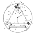
図1〜図6は、本発明の第1の実施の形態の管内面の清掃装置を示す。ここで、11は、管路を構成する鋳鉄管で、水平方向に敷設されている。12は清掃装置で、旋回体としての旋回フレーム13を備えている。この旋回フレーム13は、三つのラーメン部材14が三角形状に組み立てられた構成となっており、その三角形における二つの頂点には車輪支装置15、16が設けられており、残りの一つの頂点には回転式清掃具17が設けられている。回転式清掃具17は回転ブラシ18を備え、この回転ブラシ18と一対の車輪支持装置15、16とが管11の内面に接することで、旋回フレーム13を管11の内面に支持している。   1 to 6 show a pipe inner surface cleaning apparatus according to a first embodiment of the present invention. Here, 11 is a cast iron pipe that constitutes the pipeline, and is laid in the horizontal direction. A cleaning device 12 includes a turning frame 13 as a turning body. The swivel frame 13 has a structure in which three ramen members 14 are assembled in a triangular shape. Wheel support devices 15 and 16 are provided at two vertices of the triangle, and the remaining one vertex is provided. A rotary cleaning tool 17 is provided. The rotary cleaning tool 17 includes a rotating brush 18, and the rotating brush 18 and the pair of wheel support devices 15 and 16 are in contact with the inner surface of the tube 11, thereby supporting the swivel frame 13 on the inner surface of the tube 11.

車輪支持装置15、16は、接続体19と車輪支持体20とを有し、接続体19にはラーメン部材14の端部がボルト21によって取り外し可能な状態で固定されている。車輪支持体20は、鋳鉄管11の軸心22に沿った方向に距離をおいて配置された一対の車輪23、23を支持している。一方の車輪支持装置15では、一対の車輪23、23は、車軸24によって一体に回転するように構成されるとともに、エアモータ25によって回転駆動されるように構成されている。   Each of the wheel support devices 15 and 16 includes a connection body 19 and a wheel support body 20, and an end portion of the ramen member 14 is fixed to the connection body 19 in a state where the end portion can be removed by a bolt 21. The wheel support 20 supports a pair of wheels 23, 23 arranged at a distance in a direction along the axis 22 of the cast iron pipe 11. In the one wheel support device 15, the pair of wheels 23, 23 are configured to rotate integrally with the axle 24 and are configured to be rotationally driven by the air motor 25.

車輪支持体20は、鋳鉄管11の径方向に配置されたセンタピン26によって、接続体19に対し回転自在に連結されている。27は固定ボルトで、円弧状の長孔や別個の孔部に通されることなどによって、車輪支持体20を接続体19に対してセンタピン26の周りに所定角度だけ傾けた状態で固定させることができる。これにより、図3に示すように、車輪22の回転軸心28を鋳鉄管11の軸心22に対して所定角度だけ傾斜させることができる。   The wheel support 20 is rotatably connected to the connection body 19 by a center pin 26 arranged in the radial direction of the cast iron pipe 11. Reference numeral 27 denotes a fixing bolt, which is fixed in a state where the wheel support 20 is tilted around the center pin 26 by a predetermined angle with respect to the connection body 19 by being passed through an arc-shaped long hole or a separate hole. Can do. Thereby, as shown in FIG. 3, the rotation axis 28 of the wheel 22 can be inclined by a predetermined angle with respect to the axis 22 of the cast iron pipe 11.

回転式清掃具17において、30は清掃具支持体で、ラーメン部材14の端部がボルト21によって取り外し可能な状態で固定されている。清掃具支持体30は支持プレート31を有し、この支持プレート31には、二対すなわち4個のつば付きローラ32が回転自在に支持されている。そして、これらのつば付きローラ32によって、角筒構造の支柱33が、鋳鉄管11の径方向に移動自在に支持されている。支柱33の先端にはブラケット34が取り付けられており、このブラケット34には回転ブラシユニット35が取り付けられている。清掃具支持体30には、鋳鉄管11の径方向に伸縮する一対のエアシリンダ36が取り付けられており、このエアシリンダ36の伸縮端はブラケット34に連結されている。したがって、エアシリンダ36を作動させることで、回転ブラシユニット35を、支柱33とともに鋳鉄管11の径方向に移動させることが可能である。   In the rotary cleaning tool 17, reference numeral 30 denotes a cleaning tool support, and the end of the ramen member 14 is fixed in a detachable state by a bolt 21. The cleaning tool support 30 includes a support plate 31, and two pairs, that is, four flanged rollers 32 are rotatably supported on the support plate 31. And the support | pillar 33 of a square tube structure is supported by these collar rollers 32 so that movement to the radial direction of the cast iron pipe 11 is possible. A bracket 34 is attached to the tip of the column 33, and a rotating brush unit 35 is attached to the bracket 34. A pair of air cylinders 36 that extend and contract in the radial direction of the cast iron pipe 11 are attached to the cleaning tool support 30, and the expansion / contraction ends of the air cylinder 36 are connected to a bracket 34. Therefore, by operating the air cylinder 36, the rotating brush unit 35 can be moved together with the support 33 in the radial direction of the cast iron pipe 11.

回転ブラシユニット35において、37はハウジングで、回転ブラシ18をその回転軸心39が鋳鉄管11の軸心22に沿った方向になるように支持している。ハウジング37には、回転ブラシ18を回転駆動させるためのエアモータ40が取り付けられている。またハウジング37には、回転ブラシ18の回転軸心39の方向に距離をおいて、一対のブラケット41がボルト42によって取り付けられている。各ブラケット41には、それぞれ車輪43が支持されている。これらの一対の車輪43、43は、回転ブラシ18を間に挟んだ状態で配置されており、回転ブラシ18の回転軸心39と同方向の軸心のまわりに回転自在とされている。   In the rotary brush unit 35, reference numeral 37 denotes a housing, which supports the rotary brush 18 so that the rotation axis 39 thereof is in a direction along the axis 22 of the cast iron pipe 11. An air motor 40 for rotating the rotary brush 18 is attached to the housing 37. A pair of brackets 41 are attached to the housing 37 by bolts 42 at a distance in the direction of the rotation axis 39 of the rotary brush 18. Each bracket 41 supports a wheel 43. The pair of wheels 43, 43 are arranged with the rotary brush 18 sandwiched therebetween, and are rotatable about an axis in the same direction as the rotation axis 39 of the rotary brush 18.

エアシリンダ36が伸長すると、回転ブラシ18と車輪43、43とが鋳鉄管11の内面に押し付けられ、それに対応して車輪支持装置15、16の車輪23、23も鋳鉄管11の内面に押し付けられ、これにより清掃装置12を鋳鉄管11の内面にて支持させることができる。   When the air cylinder 36 is extended, the rotary brush 18 and the wheels 43 and 43 are pressed against the inner surface of the cast iron pipe 11, and the wheels 23 and 23 of the wheel support devices 15 and 16 are also pressed against the inner surface of the cast iron pipe 11. Thus, the cleaning device 12 can be supported on the inner surface of the cast iron pipe 11.

回転ブラシユニット35において、車輪43、43は、鋳鉄管11に対する回転ブラシ18の接触量を調節する機能を果たす。すなわち、鋳鉄管11に押し付けられていない自然な状態では、回転ブラシ18の外周の方が車輪43、43の外周よりも管径方向の外向きに突出しており、エアシリンダ36が伸長するとまず回転ブラシ18の外周が鋳鉄管11の内面に接触し、さらにエアシリンダ36が伸長すると、回転ブラシ18における鋳鉄管11への接触部が弾性変形を受けながら鋳鉄管11の内面に押圧され、最後に車輪43、43が鋳鉄管11の内周面に接触することで、回転ブラシ18が所定の接触量で鋳鉄管11の内面に接触されることになる。   In the rotary brush unit 35, the wheels 43 and 43 function to adjust the amount of contact of the rotary brush 18 with the cast iron pipe 11. In other words, in a natural state where it is not pressed against the cast iron pipe 11, the outer periphery of the rotary brush 18 protrudes outward in the pipe radial direction from the outer periphery of the wheels 43, 43, and first rotates when the air cylinder 36 extends. When the outer periphery of the brush 18 comes into contact with the inner surface of the cast iron pipe 11 and the air cylinder 36 further extends, the contact portion of the rotary brush 18 with the cast iron pipe 11 is pressed against the inner surface of the cast iron pipe 11 while undergoing elastic deformation. When the wheels 43 and 43 are in contact with the inner peripheral surface of the cast iron pipe 11, the rotary brush 18 is brought into contact with the inner surface of the cast iron pipe 11 with a predetermined contact amount.

車輪43を支持したブラケット41をハウジング37に固定するためのボルト42が、たとえば管径方向すなわちエアシリンダ36の伸縮方向の長孔に通されることによって、回転ブラシ18に対する管径方向に沿った車輪43の位置を調節することができ、それによって鋳鉄管11への回転ブラシ18の接触量を調節することができる。   A bolt 42 for fixing the bracket 41 supporting the wheel 43 to the housing 37 is passed through a long hole in the tube radial direction, that is, the expansion / contraction direction of the air cylinder 36, for example, along the tube radial direction with respect to the rotating brush 18. The position of the wheel 43 can be adjusted, whereby the amount of contact of the rotating brush 18 with the cast iron pipe 11 can be adjusted.

回転ブラシユニット35は、固定ボルト44によって、ブラケット34に対し取り外し可能な状態で固定されている。固定ボルト44が円弧状の長孔や別個の孔に通されることなどによって、回転ブラシユニット35を清掃具支持体30に対して管径方向の軸心45の周りに所定角度だけ傾けた状態で固定することができる。これにより、図3に示すように、回転ブラシ18の回転軸心39を鋳鉄管11の軸心22に対して所定角度だけ傾斜させることができる。   The rotating brush unit 35 is fixed to the bracket 34 by a fixing bolt 44 so as to be removable. A state in which the rotating brush unit 35 is inclined by a predetermined angle around the axial center 45 in the radial direction with respect to the cleaning tool support 30 by passing the fixing bolt 44 through an arc-shaped long hole or a separate hole. It can be fixed with. Thereby, as shown in FIG. 3, the rotation axis 39 of the rotary brush 18 can be inclined with respect to the axis 22 of the cast iron pipe 11 by a predetermined angle.

旋回フレーム13のラーメン部材14には、支持アーム48が取り付けられている。この支持アーム48は、その先端が三角形状の旋回アーム13の中心部に位置するように構成されている。そして支持アーム48の先端には、多連ロータリスイベル49が設けられている。多連ロータリスイベル49には、旋回フレーム13の外部からのエア配管や洗浄水配管などの配管50が接続されるとともに、旋回フレーム13におけるエアモータ25、40やエアシリンダ36へのエア配管や回転ブラシユニットへの洗浄水配管などの配管51が接続されている。旋回フレーム13の外部における配管50には、操作バルブ52が設けられている。   A support arm 48 is attached to the frame member 14 of the revolving frame 13. The support arm 48 is configured such that the tip thereof is positioned at the center of the triangular swing arm 13. A multiple rotary swivel 49 is provided at the tip of the support arm 48. The multiple rotary swivel 49 is connected to a pipe 50 such as an air pipe or a washing water pipe from the outside of the swivel frame 13, and air pipes and rotary brushes to the air motors 25 and 40 and the air cylinder 36 in the swivel frame 13. A pipe 51 such as a washing water pipe to the unit is connected. An operation valve 52 is provided in the pipe 50 outside the revolving frame 13.

後述のように、旋回フレーム13は鋳鉄管11の軸心22の回りにおいて旋回動を行う。多連ロータリスイベル49における外部の配管50が接続された部分には、この部分が旋回フレーム13の旋回動にかかわらず常に一定の姿勢を維持するように、ウエイト53が偏心状態で取り付けられている。   As will be described later, the swivel frame 13 swivels around the axis 22 of the cast iron pipe 11. A weight 53 is attached in an eccentric state to a portion of the multiple rotary swivel 49 to which the external pipe 50 is connected so that this portion always maintains a constant posture regardless of the turning motion of the turning frame 13. .

鋳鉄管11の内部における洗浄作業について説明する。図1および図2に示すようにエアシリンダ36を伸長させて回転ブラシ18と車輪23、23とを鋳鉄管11の内面に押し付けることにより清掃装置12を支持させ、この状態で車輪支持装置15のエアモータ25により車輪23を駆動させると、清掃装置12は、鋳鉄管11の軸心22のまわりにゆっくりと回転する。そして、この状態で回転式清掃具17のエアモータ40により回転ブラシ18を回転駆動させことにより、鋳鉄管11の内面を周方向に沿って洗浄することができる。このとき、回転式清掃具17に洗浄水を送って図2に示す噴射ノズル54から回転ブラシ18に供給することで、効果的な洗浄を行うことが可能である。   The cleaning operation inside the cast iron pipe 11 will be described. As shown in FIGS. 1 and 2, the air cylinder 36 is extended to press the rotating brush 18 and the wheels 23, 23 against the inner surface of the cast iron pipe 11 to support the cleaning device 12. In this state, the wheel support device 15 When the wheel 23 is driven by the air motor 25, the cleaning device 12 rotates slowly around the axis 22 of the cast iron pipe 11. In this state, the inner surface of the cast iron pipe 11 can be cleaned along the circumferential direction by rotating the rotary brush 18 by the air motor 40 of the rotary cleaning tool 17. At this time, it is possible to perform effective cleaning by sending cleaning water to the rotary cleaning tool 17 and supplying it to the rotating brush 18 from the spray nozzle 54 shown in FIG.

この場合において、図3に示すように、車輪支持装置15、16における車輪23の回転軸心28を鋳鉄管11の軸心22に対して傾斜させ、かつ回転ブラシ18の回転軸心39も同様に傾斜させることによって、回転ブラシユニット35を鋳鉄管11の内面に沿ってらせん状に移動させることができる。したがって、鋳鉄管11の内面を、その全周かつ軸心22の方向にわたって、確実に清掃することができる。したがって、作業者の人手による清掃作業が不要となり、しかも鋳鉄管11の上部を清掃するときに足場を組む必要もないため、効率よくかつ安全に清掃を行うことができる。   In this case, as shown in FIG. 3, the rotation axis 28 of the wheel 23 in the wheel support devices 15, 16 is inclined with respect to the axis 22 of the cast iron pipe 11, and the rotation axis 39 of the rotary brush 18 is the same. The rotary brush unit 35 can be spirally moved along the inner surface of the cast iron tube 11 by being inclined to the angle. Therefore, the inner surface of the cast iron pipe 11 can be reliably cleaned over the entire circumference and the direction of the axis 22. Therefore, it is not necessary to perform a manual cleaning operation by an operator, and it is not necessary to form a scaffold when cleaning the upper part of the cast iron pipe 11, so that the cleaning can be performed efficiently and safely.

場合によっては回転ブラシ18による洗浄の際の回転力によって旋回フレーム13を旋回駆動させることができ、その場合には車輪支持装置15のエアモータ25による車輪23の駆動は不要になる。   In some cases, the turning frame 13 can be driven to turn by the rotational force during the cleaning by the rotating brush 18, and in this case, the driving of the wheel 23 by the air motor 25 of the wheel support device 15 becomes unnecessary.

また、上記においては、回転ブラシ18の回転軸心39を鋳鉄管11の軸心22に対して傾斜させたものについて説明したが、これに代えて、回転ブラシ18はその回転軸心39が鋳鉄管11の軸心に沿った方向に配置し、車輪43、43の軸心のみを傾斜させるようにしてもよい。このような傾斜は、ブラケット41に対する車輪43の取り付け角度を調節することによって付与することができる。   Further, in the above description, the rotation axis 39 of the rotary brush 18 is inclined with respect to the axis 22 of the cast iron tube 11. Instead, the rotary brush 18 has a rotation axis 39 of cast iron. It may be arranged in a direction along the axis of the tube 11 and only the axes of the wheels 43 and 43 may be inclined. Such inclination can be imparted by adjusting the mounting angle of the wheel 43 with respect to the bracket 41.

管内面の洗浄装置12は、上記のような構成であるために、ボルト21や固定ボルト27、44を操作することによって、分解・組み立てを行うことができる。すなわち、図1および図2に示された組み立て状態から、図4に示すように、旋回フレーム13を構成するそれぞれのラーメン部材14と、車輪支持装置15、16と、回転式清掃具17におけるローラ32およびエアシリンダ36付きの清掃具支持体30と、回転式清掃具17におけるブラケット34付き支柱33と、回転式清掃具17における回転ブラシユニット35とに分解することができる。   Since the pipe inner surface cleaning device 12 has the above-described configuration, it can be disassembled and assembled by operating the bolt 21 and the fixing bolts 27 and 44. That is, from the assembled state shown in FIGS. 1 and 2, as shown in FIG. 4, the respective ramen members 14 constituting the revolving frame 13, the wheel support devices 15 and 16, and the rollers in the rotary cleaning tool 17. 32 and the cleaning tool support 30 with the air cylinder 36, the column 33 with the bracket 34 in the rotary cleaning tool 17, and the rotating brush unit 35 in the rotary cleaning tool 17.

よって、洗浄作業のために本装置12を鋳鉄管11の内部に搬入する際には、図4に示す分解状態のものを、マンホール55を通して管内に運び込み、管内で図1および図2に示す状態となるように組み立てを行えばよい。反対に、洗浄作業の終了後に本装置12を鋳鉄管11の外部に搬出するときには、管内で分解を行ったうえで、同様に図4に示すようにマンホール55を通して取り出せばよい。   Therefore, when the present apparatus 12 is carried into the cast iron pipe 11 for cleaning work, the disassembled state shown in FIG. 4 is carried into the pipe through the manhole 55, and the state shown in FIGS. 1 and 2 in the pipe. Assembling may be performed so that On the other hand, when the present apparatus 12 is taken out of the cast iron pipe 11 after the cleaning operation is completed, it should be taken out through the manhole 55 as shown in FIG.

洗浄作業を行うべき場所がマンホール55から離れているときは、図5および図6に示すような台車56を用いることによって、鋳鉄管11の内部において清掃装置12を運搬することができる。すなわち、回転式清掃具17におけるエアシリンダ36を短縮させると、図示のように回転ブラシ18が鋳鉄管11の径方向に沿った内向きに移動して鋳鉄管11の内面から離れるので、一つのラーメン部材14の下に台車56を入り込ませ、この台車56に設けられたねじジャッキ57にてこのラーメン部材14を支持して持ち上げることにより、車輪支持装置15、16の車輪23、23を鋳鉄管11の内面から浮かせる。これにより、作業者58が台車56を移動させることによって、清掃装置12を鋳鉄管11の内部において移動させることができる。所定の場所に到着したなら、ねじジャッキ57を操作して清掃装置12を降ろし、車輪23、23を鋳鉄管11の内面に接触させる。   When the place where the cleaning operation is to be performed is away from the manhole 55, the cleaning device 12 can be transported inside the cast iron pipe 11 by using the carriage 56 as shown in FIGS. That is, when the air cylinder 36 in the rotary cleaning tool 17 is shortened, the rotating brush 18 moves inward along the radial direction of the cast iron pipe 11 and is separated from the inner surface of the cast iron pipe 11 as shown in FIG. A carriage 56 is inserted under the ramen member 14, and the ramen member 14 is supported and lifted by a screw jack 57 provided on the carriage 56, so that the wheels 23 and 23 of the wheel support devices 15 and 16 are cast iron pipes. 11 from the inner surface. Thereby, the cleaning device 12 can be moved inside the cast iron pipe 11 by the operator 58 moving the carriage 56. When it reaches a predetermined place, the screw jack 57 is operated to lower the cleaning device 12, and the wheels 23 and 23 are brought into contact with the inner surface of the cast iron pipe 11.

回転ブラシ18は、樹脂などの植毛によって構成することができ、これによって鋳鉄管11の内面に付着したマンガンを効果的に清掃することができる。これに代えて、図7に示すように鋳鉄管11の内部に錆こぶなどの異物60が発生しており、これを清掃する必要がある場合には、図7に示す構成の回転式清掃具17を用いることが好適である。すなわち、この図7に示す回転式清掃具17では、回転軸61に複数の金属製の短尺チェーン62が放射状に取り付けられており、この放射状の短尺チェーン62が回転軸の長さ方向に沿った複数の位置に設けられた構成となっている。   The rotating brush 18 can be constituted by flocking of resin or the like, thereby effectively cleaning manganese adhering to the inner surface of the cast iron pipe 11. Instead, as shown in FIG. 7, when a foreign matter 60 such as rust is generated inside the cast iron pipe 11 and it is necessary to clean it, the rotary cleaning tool having the configuration shown in FIG. It is preferable to use 17. That is, in the rotary cleaning tool 17 shown in FIG. 7, a plurality of metal short chains 62 are radially attached to the rotary shaft 61, and the radial short chains 62 extend along the length direction of the rotary shaft. The configuration is provided at a plurality of positions.

このような構成であると、回転軸61の回転力によって短尺チェーン62の先端が錆こぶなどの異物60にたたき付けられ、それによって異物60を破砕させて清掃を行うことができる。   With such a configuration, the distal end of the short chain 62 is struck by a foreign matter 60 such as a rust hump by the rotational force of the rotary shaft 61, whereby the foreign matter 60 can be crushed and cleaned.

図8〜図10は、本発明の第2の実施の形態の管内面の清掃装置を示す。ここでは、鋳鉄管11の内部をその軸心22の方向に移動可能な台車65の先端に旋回フレーム66が設けられている。   8 to 10 show a pipe inner surface cleaning apparatus according to a second embodiment of the present invention. Here, a turning frame 66 is provided at the tip of a carriage 65 that can move inside the cast iron pipe 11 in the direction of its axis 22.

台車65は鋳鉄管11の軸心22と平行な方向に配置されたテーブル67を有し、このテーブル67には斜め下向きの4本の脚部68が接続されている。脚部68の下端には、軸心22と平行な方向に配置された一対の車輪支持体69、69が接続されている。それぞれの車輪支持体69には、一対の車輪70、70が、軸心22と平行な方向に距離をおいて配置されている。車輪70、70は、台車65を軸心22と平行な方向に走行させることが可能である。   The carriage 65 has a table 67 arranged in a direction parallel to the axis 22 of the cast iron pipe 11, and four leg portions 68 obliquely downward are connected to the table 67. A pair of wheel supports 69, 69 arranged in a direction parallel to the shaft center 22 is connected to the lower end of the leg portion 68. Each wheel support 69 has a pair of wheels 70, 70 arranged at a distance in a direction parallel to the axis 22. The wheels 70 and 70 can cause the carriage 65 to travel in a direction parallel to the axis 22.

台車65のテーブル67の上部では、このテーブル67と、軸心22と平行な方向に配置された上部車輪支持体71と、一対のリンク部材72、72とによって、平行リンク機構73が構成されている。テーブル67と上部車輪支持体71との間にはエアシリンダ74が設けられており、このエアシリンダ74が伸縮することで平行リンク機構73が揺動されることによって、上部車輪支持体71が、軸心22と平行な状態を維持しながら昇降されるように構成されている。上部車輪支持体71には、一対の車輪75、75が、軸心22と平行な方向に距離をおいて配置されている。上部車輪支持体71を上昇させることで、車輪75、75を鋳鉄管11の頂部の内面に接触させることができる。この状態で、車輪75、75は、車輪70、70と同様に、台車65を軸心22と平行な方向に走行させることが可能である。   In the upper part of the table 67 of the carriage 65, a parallel link mechanism 73 is constituted by the table 67, the upper wheel support 71 arranged in a direction parallel to the shaft center 22, and a pair of link members 72, 72. Yes. An air cylinder 74 is provided between the table 67 and the upper wheel support 71, and the parallel link mechanism 73 is swung by the expansion and contraction of the air cylinder 74, whereby the upper wheel support 71 is It is configured to be lifted and lowered while maintaining a state parallel to the shaft center 22. On the upper wheel support 71, a pair of wheels 75, 75 are arranged at a distance in a direction parallel to the axis 22. By raising the upper wheel support 71, the wheels 75, 75 can be brought into contact with the inner surface of the top of the cast iron pipe 11. In this state, the wheels 75 and 75 can cause the carriage 65 to travel in a direction parallel to the shaft center 22, similarly to the wheels 70 and 70.

すなわち、台車65は、車輪70が鋳鉄管11の下部の内面における周方向に沿った2箇所に接するとともに、車輪75が鋳鉄管11の頂部の内面に接し、それによってテーブル67が軸心22に沿った位置に保持された状態で、鋳鉄管11の内部を軸心22の方向に移動自在である。   That is, in the bogie 65, the wheel 70 is in contact with two locations along the circumferential direction on the inner surface of the lower portion of the cast iron pipe 11, and the wheel 75 is in contact with the inner surface of the top portion of the cast iron pipe 11. The inside of the cast iron pipe 11 can be moved in the direction of the axis 22 while being held at the position along.

台車65のテーブル67の上には、軸心22の方向に距離をおいた一対の軸受76、76によって、回転軸77が、軸心22に対応した位置に支持されている。テーブル67の下面には、回転軸77を回転駆動するためのエアモータ78が設けられている。   On the table 67 of the carriage 65, a rotating shaft 77 is supported at a position corresponding to the shaft center 22 by a pair of bearings 76, 76 spaced in the direction of the shaft center 22. An air motor 78 for rotating the rotary shaft 77 is provided on the lower surface of the table 67.

回転軸77の先端には、多連スイベル80を介して、フレームホルダ81が接続されている。フレームホルダ81は支持部材82を有し、この支持部材82には、二対すなわち4個のつば付きローラ83が回転自在に支持されている。旋回フレーム66は角筒構造の支柱84を有し、この支柱84は、つば付きローラ83によって、鋳鉄管11の径方向に支持されるとともに、この径方向に移動自在とされている。   A frame holder 81 is connected to the tip of the rotating shaft 77 via a multiple swivel 80. The frame holder 81 has a support member 82, and two pairs, that is, four flanged rollers 83 are rotatably supported by the support member 82. The revolving frame 66 includes a column 84 having a rectangular tube structure. The column 84 is supported by a flanged roller 83 in the radial direction of the cast iron pipe 11 and is movable in the radial direction.

支柱84の一端には、取付けフランジ85を介して、車輪支持体86が取り付けられている。車輪支持体86は、軸心22と平行な方向に沿って距離をおいて配置された一対の車輪87、87を支持している。各車輪87は、鋳鉄管11の内周面に沿って走行可能とされている。   A wheel support 86 is attached to one end of the column 84 via an attachment flange 85. The wheel support 86 supports a pair of wheels 87 and 87 arranged at a distance along a direction parallel to the axis 22. Each wheel 87 can travel along the inner peripheral surface of the cast iron pipe 11.

支柱84の他端には、テレスコピック部88を介して、回転ブラシユニット35が取り付けられている。回転ブラシユニット35の構成は、前述の第1の実施の形態のものと同じである。テレスコピック部88では、支柱84を構成する外角筒89の内部に内角筒90がはめ込まれた構成となっており、さらに内角筒90の内部にエアシリンダ91が設けられている。エアシリンダ91は、その基端部が外角筒89に接続されるとともに、その伸縮端が、内角筒90の先端に設けられた取付けフランジ92に接続されている。   The rotating brush unit 35 is attached to the other end of the support 84 via a telescopic portion 88. The configuration of the rotating brush unit 35 is the same as that of the first embodiment described above. The telescopic portion 88 has a configuration in which an inner rectangular tube 90 is fitted inside an outer rectangular tube 89 that constitutes the support column 84, and an air cylinder 91 is provided inside the inner rectangular tube 90. The air cylinder 91 has a base end connected to the outer square tube 89 and an extendable end connected to a mounting flange 92 provided at the tip of the inner square tube 90.

したがって、エアシリンダ91を伸縮させることによってテレスコピック部88を伸縮させることができ、エアシリンダ91を伸長させることによって、回転ブラシユニット35の回転ブラシ18と車輪87とを鋳鉄管11の内面に押し付け状態で接触させることができる。またエアシリンダ91を短縮させることによって、回転ブラシ18および車輪87の鋳鉄管11の内面への押し付け力を解除したり、回転ブラシ18と車輪87との少なくともいずれかを鋳鉄管11の内面から浮かせたりすることが可能である。このとき、角筒構造の支柱84がつば付きローラ83によって鋳鉄管11の径方向に移動自在に支持され、したがって支柱84は回転軸77による管径方向の位置規制を受けないため、エアシリンダ91による特に鋳鉄管11の内面への回転ブラシ18の押し付けを支障なく良好に行うことができる。   Therefore, the telescopic portion 88 can be expanded and contracted by expanding and contracting the air cylinder 91, and the rotating brush 18 and the wheel 87 of the rotating brush unit 35 are pressed against the inner surface of the cast iron pipe 11 by extending the air cylinder 91. Can be contacted. Further, by shortening the air cylinder 91, the pressing force of the rotating brush 18 and the wheel 87 against the inner surface of the cast iron pipe 11 is released, or at least one of the rotating brush 18 and the wheel 87 is floated from the inner surface of the cast iron pipe 11. It is possible to At this time, the pillar 84 having a rectangular tube structure is supported by the flanged roller 83 so as to be movable in the radial direction of the cast iron pipe 11, and therefore the pillar 84 is not subjected to position restriction in the pipe radial direction by the rotating shaft 77. In particular, the pressing of the rotary brush 18 to the inner surface of the cast iron pipe 11 can be performed satisfactorily without any trouble.

車輪支持体86は、取付けフランジ85において、ボルト93によって支柱84に固定されている。また回転ブラシユニット35は、取付けフランジ92において、同様にボルト93によって支柱84の伸縮端に固定されている。これらのボルト93が円弧状の長孔や別個の孔に通されることなどによって、図3に示したものと同様に、回転ブラシ18の回転軸心39を鋳鉄管11の軸心22に対して所定角度だけ傾斜させることができるとともに、車輪支持体86すなわち車輪87の回転軸心を、同様に鋳鉄管11の軸心22に対して所定角度だけ傾斜させることができる。   The wheel support 86 is fixed to the column 84 by bolts 93 at the mounting flange 85. In addition, the rotating brush unit 35 is fixed to the telescopic end of the support column 84 by a bolt 93 in the mounting flange 92 in the same manner. As these bolts 93 are passed through arc-shaped elongated holes or separate holes, the rotational axis 39 of the rotary brush 18 is moved relative to the axial center 22 of the cast iron pipe 11 in the same manner as shown in FIG. The wheel support 86, that is, the rotation axis of the wheel 87 can be similarly inclined with respect to the axis 22 of the cast iron pipe 11 by a predetermined angle.

台車65において、脚部68は、その上端に設けた取付け取外し部94によってテーブル67に対し着脱可能とされている。またその下端に設けた取付け取外し部95によって車輪支持体69に対し着脱可能とされている。よって、台車65は、図8〜図10に示す組立状態から、平行リンク機構73を含むテーブル67と、車輪70を含む一対の車輪支持体69と、4本の脚部68とに分解可能である。また旋回フレーム66は、支柱84の両端の取付けフランジ85、82においてボルト93をゆるめることによって、図8および図9に示す組立状態から、支柱84と、回転ブラシユニット35と、車輪87を含む車輪支持体86とに分解可能である。図4に示したものと同様に、分解状態の平行リンク機構73を含むテーブル67と、車輪70を含む一対の車輪支持体69と、4本の脚部68
と、支柱84と、回転ブラシユニット35と、車輪87を含む車輪支持体86とは、いずれもマンホールを通して鋳鉄管11の内外の間で搬送することができる。
In the carriage 65, the leg portion 68 is detachable from the table 67 by an attachment / detachment portion 94 provided at the upper end thereof. The wheel support 69 is detachable by an attachment / detachment portion 95 provided at the lower end thereof. Therefore, the cart 65 can be disassembled into the table 67 including the parallel link mechanism 73, the pair of wheel supports 69 including the wheels 70, and the four legs 68 from the assembled state illustrated in FIGS. 8 to 10. is there. Further, the swing frame 66 is a wheel including the support 84, the rotating brush unit 35, and the wheel 87 from the assembled state shown in FIGS. 8 and 9 by loosening the bolts 93 at the mounting flanges 85 and 82 at both ends of the support 84. The support 86 can be disassembled. Similar to the one shown in FIG. 4, the table 67 including the parallel link mechanism 73 in the disassembled state, the pair of wheel supports 69 including the wheels 70, and the four legs 68.
And the support | pillar 84, the rotating brush unit 35, and the wheel support body 86 containing the wheel 87 can all be conveyed between the inside and outside of the cast iron pipe 11 through a manhole.

図示は省略するが、台車65にはエア配管や洗浄水配管が導入されており、これらの配管は、多連スイベル80を介して旋回フレーム66に導かれている。エア配管は、台車65におけるエアモータ78やエアシリンダ74にも接続されている。   Although illustration is omitted, an air pipe and a washing water pipe are introduced into the carriage 65, and these pipes are led to the swivel frame 66 through a multiple swivel 80. The air pipe is also connected to an air motor 78 and an air cylinder 74 in the carriage 65.

鋳鉄管11の内部における洗浄作業について説明する。図8および図10に示すようにエアシリンダ74を伸長させて車輪70、75を鋳鉄管11の内面に押し付けることで、台車65が鋳鉄管11に対して保持される。この状態で旋回フレーム66のエアシリンダ91を伸長させると、車輪87が鋳鉄管11の内面に接した状態で、回転ブラシ18が鋳鉄管11の内面に押し付けられる。   The cleaning operation inside the cast iron pipe 11 will be described. As shown in FIGS. 8 and 10, the carriage 65 is held against the cast iron pipe 11 by extending the air cylinder 74 and pressing the wheels 70 and 75 against the inner surface of the cast iron pipe 11. When the air cylinder 91 of the revolving frame 66 is extended in this state, the rotating brush 18 is pressed against the inner surface of the cast iron pipe 11 with the wheels 87 in contact with the inner surface of the cast iron pipe 11.

そこで、エアモータ78によって回転軸77をゆっくりと回転させると、それにつれて旋回フレーム66も同様に回転される。その状態で、噴射ノズル54から洗浄水を噴射させながら、エアモータ40により回転ブラシ18を回転駆動させる。すると、回転ブラシ18を鋳鉄管11の周方向に移動させながらこの鋳鉄管11の内面を洗浄することができる。   Therefore, when the rotary shaft 77 is slowly rotated by the air motor 78, the turning frame 66 is similarly rotated accordingly. In this state, the rotary brush 18 is driven to rotate by the air motor 40 while the cleaning water is jetted from the jet nozzle 54. Then, the inner surface of the cast iron pipe 11 can be cleaned while moving the rotating brush 18 in the circumferential direction of the cast iron pipe 11.

このとき、上述のように、回転ブラシ18の回転軸心39を鋳鉄管11の軸心22に対して所定角度だけ傾斜させ、かつ車輪87の回転軸心を同様に鋳鉄管11の軸心22に対して所定角度だけ傾斜させることで、回転ブラシ18がらせん状の軌跡を描くことになって、鋳鉄管11の内面を、その全周かつ軸心22の方向にわたって、確実に清掃することができる。台車65は、回転ブラシ18がらせん状に運動することに追随して、旋回フレーム66を支持しながら、鋳鉄管11の内部を軸心22の方向に移動する。これにより、上述の第1の実施の形態の場合と同様に、作業者の人手による清掃作業が不要となり、しかも鋳鉄管11の頂部を清掃するときに足場を組む必要もないため、効率よくかつ安全に清掃を行うことができる。   At this time, as described above, the rotational axis 39 of the rotary brush 18 is inclined by a predetermined angle with respect to the axial center 22 of the cast iron pipe 11, and the rotational axis of the wheel 87 is similarly the axial center 22 of the cast iron pipe 11. In this case, the rotating brush 18 draws a spiral trajectory, and the inner surface of the cast iron pipe 11 can be reliably cleaned over the entire circumference and the direction of the axis 22. it can. The carriage 65 follows the movement of the rotating brush 18 in a spiral, and moves inside the cast iron pipe 11 in the direction of the axis 22 while supporting the turning frame 66. As a result, as in the case of the first embodiment described above, it is not necessary to perform a manual cleaning operation by an operator, and it is not necessary to assemble a scaffold when cleaning the top portion of the cast iron pipe 11, so that it is efficient and Safe cleaning is possible.

鋳鉄管11の内部において図示の装置を運搬する場合には、たとえば旋回フレーム66を水平方向の姿勢としたうえでエアシリンダ91により回転ブラシ18を鋳鉄管11の内面から離し、この回転ブラシ18と車輪87とをともに鋳鉄管11の内面に接触しない状態とする。かつ、この状態の旋回フレーム66をフレームホルダ81によって支持する。そして、その状態で台車65を走行させることにより、鋳鉄管11の内部を移動させることができる。   When the illustrated apparatus is transported inside the cast iron pipe 11, for example, after the revolving frame 66 is in a horizontal orientation, the rotary brush 18 is separated from the inner surface of the cast iron pipe 11 by the air cylinder 91. Both the wheels 87 are not in contact with the inner surface of the cast iron pipe 11. In addition, the swivel frame 66 in this state is supported by the frame holder 81. And the inside of the cast iron pipe 11 can be moved by making the trolley | bogie 65 drive | work in that state.

図8〜図10に示すものにおいても、回転ブラシ18による洗浄の際の回転力によって旋回フレーム66を旋回駆動させることができる場合には、エアモータ78によって回転軸77を回転させることは不要になる。   8 to 10, it is not necessary to rotate the rotation shaft 77 by the air motor 78 when the rotation frame 66 can be driven to rotate by the rotational force at the time of cleaning by the rotary brush 18. .

また、第1の実施の形態と同様に、回転ブラシ18の回転軸心39を鋳鉄管11の軸心22に対して傾斜させることに代えて、回転ブラシ18はその回転軸心39が鋳鉄管11の軸心に沿った方向に配置し、車輪43、43の軸心のみを傾斜させるようにしてもよい。   Further, as in the first embodiment, instead of inclining the rotation axis 39 of the rotary brush 18 with respect to the axis 22 of the cast iron pipe 11, the rotary brush 18 has a rotation axis 39 of the cast iron pipe. 11 may be arranged in a direction along the axis of 11 and only the axes of the wheels 43 and 43 may be inclined.

図8〜図10に示す第2の実施の形態においても、回転ブラシ18に代えて、図7に示すような短尺チェーン62を用いた構成を採用することもできる。   Also in the second embodiment shown in FIGS. 8 to 10, a configuration using a short chain 62 as shown in FIG. 7 can be adopted instead of the rotating brush 18.

図11は、本発明の第3の実施の形態の管内面の清掃装置を示す。ここでは、三又構造の脚部96の先端が鋳鉄管11の内面を押圧することによってこの脚部96を支持している。脚部96の中心には鋳鉄管11の軸心22に平行な方向の回転軸97が設けられている。脚部96はその先端にジャッキ構造の位置調整装置98を備えており、この位置調整装置98によって各脚部96の長さを調節することで、回転軸97の回転軸心を鋳鉄管11の軸心22に一致させることができる。回転軸97には旋回アーム99が取り付けられており、この旋回アーム99は、この旋回アーム99に設けられた操作レバー100を作業者が操作することによって、回転軸97の周りに旋回される。旋回アーム99の旋回端には、図7に示すものと同様の回転式清掃具17が設けられている。すなわち、この清掃具17は回転軸61と短尺チェーン62とを有した構成とされている。回転軸61すなわち短尺チェーン62は、エアモータ101からの動力によって回転駆動される。   FIG. 11 shows a pipe inner surface cleaning apparatus according to a third embodiment of the present invention. Here, the leg 96 is supported by the tip of the leg 96 having a trifurcated structure pressing the inner surface of the cast iron pipe 11. At the center of the leg portion 96, a rotating shaft 97 is provided in a direction parallel to the axis 22 of the cast iron pipe 11. The leg portion 96 is provided with a jack-type position adjusting device 98 at the tip thereof, and the length of each leg portion 96 is adjusted by the position adjusting device 98 so that the rotation axis of the rotating shaft 97 is aligned with that of the cast iron pipe 11. It can be made to coincide with the axis 22. A turning arm 99 is attached to the rotating shaft 97, and the turning arm 99 is turned around the rotating shaft 97 when an operator operates an operation lever 100 provided on the turning arm 99. A rotary cleaning tool 17 similar to that shown in FIG. 7 is provided at the turning end of the turning arm 99. That is, the cleaning tool 17 is configured to have a rotating shaft 61 and a short chain 62. The rotating shaft 61, that is, the short chain 62 is rotated by power from the air motor 101.

このようなものにおいても、回転式清掃具17の短尺チェーン62をモータ101によって回転駆動させながら、旋回アーム99を旋回させることで、鋳鉄管11の内面に発生した錆こぶなどの異物60を効果的に除去することができる。   Even in such a case, by turning the turning arm 99 while rotating the short chain 62 of the rotary cleaning tool 17 by the motor 101, the foreign matter 60 such as rust humps generated on the inner surface of the cast iron pipe 11 can be effectively obtained. Can be removed.

なお、図11に示される脚部96および旋回アーム99を備えた構成において、上述の第1の実施の形態や第2の実施の形態における回転ブラシユニット35を適用することもできる。   In addition, in the structure provided with the leg part 96 and the turning arm 99 shown in FIG. 11, the rotating brush unit 35 in the first embodiment or the second embodiment described above can be applied.

本発明の第1の実施の形態の管内面の清掃装置の正面図である。It is a front view of the cleaning device of the pipe inner surface of a 1st embodiment of the present invention. 図1に示す清掃装置の側面図である。It is a side view of the cleaning apparatus shown in FIG. 図1に示す清掃装置の平面視の概略図である。It is the schematic of the planar view of the cleaning apparatus shown in FIG. 図1に示す清掃装置を構成する各部品をマンホールとともに示す図である。It is a figure which shows each component which comprises the cleaning apparatus shown in FIG. 1 with a manhole. 図1に示す清掃装置を管内において搬送する様子を示す図である。It is a figure which shows a mode that the cleaning apparatus shown in FIG. 1 is conveyed in a pipe | tube. 図5に示す状態についての側面図である。It is a side view about the state shown in FIG. 回転式清掃具の他の例を示す図である。It is a figure which shows the other example of a rotary cleaning tool. 本発明の第2の実施の形態の管内面の清掃装置の正面図である。It is a front view of the cleaning apparatus of the pipe inner surface of the 2nd Embodiment of this invention. 図8に示す清掃装置の左側面図である。It is a left view of the cleaning apparatus shown in FIG. 図8に示す清掃装置の右側面図である。It is a right view of the cleaning apparatus shown in FIG. 本発明の第3の実施の形態の管内面の清掃装置の概略構成を示す図である。It is a figure which shows schematic structure of the cleaning apparatus of the pipe inner surface of the 3rd Embodiment of this invention. 従来の管内面の清掃装置の概略構成を示す図である。It is a figure which shows schematic structure of the cleaning apparatus of the conventional pipe inner surface.

符号の説明Explanation of symbols

11 鋳鉄管
13 旋回アーム
17 回転式清掃具
18 回転ブラシ
22 軸心
23 車輪
35 回転ブラシユニット
36 エアシリンダ
39 回転軸心
62 短尺チェーン
65 台車
66 旋回フレーム
84 支柱
87 車輪
DESCRIPTION OF SYMBOLS 11 Cast iron pipe 13 Rotating arm 17 Rotating cleaning tool 18 Rotating brush 22 Axis center 23 Wheel 35 Rotating brush unit 36 Air cylinder 39 Rotating axis 62 Short chain 65 Cart 66 Swivel frame 84 Column 87 Wheel

Claims (3)

管内において旋回可能な旋回体と、この旋回体の旋回端に設けられて管内面を清掃可能な回転式清掃具とを有し、
回転式清掃具は、その回転軸心が管の軸心と平行な方向に対して傾斜した状態で設置されていることを特徴とする管内面の清掃装置。
A turning member pivotable in tubes, possess a cleanable rotary cleaning tool a luminal surface provided on the turning end of the swing body,
The rotary cleaning tool is installed in a pipe inner surface cleaning apparatus , wherein the rotary axis is installed in a state where the axis of rotation is inclined with respect to a direction parallel to the axis of the pipe.
旋回体は、管内面に支持された状態で管内において旋回可能な旋回フレームであることを特徴とする請求項1記載の管内面の清掃装置。   2. The pipe inner surface cleaning device according to claim 1, wherein the swirl body is a swivel frame that can be swung in the pipe while being supported on the pipe inner face. 旋回体は、回転式清掃具と車輪とによって管内面に支持されており、車輪は、その回転軸心が管の軸心と平行な方向に対して傾斜した状態で設置されていることを特徴とする請求項1又は2記載の管内面の清掃装置。 The swivel body is supported on the inner surface of the pipe by a rotary cleaning tool and a wheel, and the wheel is installed in a state in which the rotation axis is inclined with respect to a direction parallel to the axis of the pipe. The pipe inner surface cleaning apparatus according to claim 1 or 2 .
JP2007105380A 2007-04-13 2007-04-13 Pipe inner surface cleaning device Active JP4906568B2 (en)

Priority Applications (1)

Application Number Priority Date Filing Date Title
JP2007105380A JP4906568B2 (en) 2007-04-13 2007-04-13 Pipe inner surface cleaning device

Applications Claiming Priority (1)

Application Number Priority Date Filing Date Title
JP2007105380A JP4906568B2 (en) 2007-04-13 2007-04-13 Pipe inner surface cleaning device

Publications (2)

Publication Number Publication Date
JP2008259975A JP2008259975A (en) 2008-10-30
JP4906568B2 true JP4906568B2 (en) 2012-03-28

Family

ID=39982872

Family Applications (1)

Application Number Title Priority Date Filing Date
JP2007105380A Active JP4906568B2 (en) 2007-04-13 2007-04-13 Pipe inner surface cleaning device

Country Status (1)

Country Link
JP (1) JP4906568B2 (en)

Families Citing this family (1)

* Cited by examiner, † Cited by third party
Publication number Priority date Publication date Assignee Title
KR102056049B1 (en) * 2013-09-11 2019-12-17 대우조선해양 주식회사 Large caliber vertical pipe cleaner

Family Cites Families (2)

* Cited by examiner, † Cited by third party
Publication number Priority date Publication date Assignee Title
JPS62292563A (en) * 1986-06-13 1987-12-19 株式会社イセキ開発工機 Self-advancing device in pipe
JPH0985206A (en) * 1995-05-19 1997-03-31 Nitto Seiko Co Ltd Debris removal device in pipe

Also Published As

Publication number Publication date
JP2008259975A (en) 2008-10-30

Similar Documents

Publication Publication Date Title
US5238331A (en) Modularized machine for reconditioning pipelines
JP5921937B2 (en) Rotating self-propelled in-pipe cleaning machine
CN113696064A (en) Metal surface rust removal spraying equipment for green building
KR101942175B1 (en) Bearing automatic cleaner
CN201264028Y (en) Bearing cleaning machine
KR100871985B1 (en) Conduit Descaling and Surface Treatment Units
CN113083579B (en) Method for repairing surface defect of aluminum alloy automobile hub
JP2008249213A (en) Method and apparatus for treating inner surface of cylindrical body
KR100805853B1 (en) Hollow Cylindrical Cleaning Device
PT2503208E (en) System for maintenance of inner conduit surface and related process
CA1074563A (en) Machine for treating pipe interiors
JP4906568B2 (en) Pipe inner surface cleaning device
JP3812454B2 (en) Equipment for cleaning the inner surface of cylindrical objects
CN215198705U (en) Automatic cleaning device for surface of cold-rolled tube
CN216152026U (en) Rust removal device for natural gas pipeline installation
CN215810446U (en) Be used for abluent rotation cleaning equipment of air preheater
CN207509039U (en) A kind of derusting device
CN104492646A (en) Haze elimination device
FI3426435T3 (en) Manipulator and manipulator unit
JP2002029394A (en) Vehicle cleaning device and vehicle cleaning system
JP2000218547A (en) Blast device for inner surface of steel pipe or the like
CN117483358A (en) Spherical cleaning machine for variable-size pumping concrete conveying pipeline
CN216940160U (en) High-pressure water spraying rust removal device for track and dock bottom vehicle
CN117415111A (en) A spherical cleaning machine for pumping concrete conveying pipes
CN214555898U (en) Laser cleaning device for cleaning tire

Legal Events

Date Code Title Description
A621 Written request for application examination

Free format text: JAPANESE INTERMEDIATE CODE: A621

Effective date: 20100331

A711 Notification of change in applicant

Free format text: JAPANESE INTERMEDIATE CODE: A711

Effective date: 20100511

A521 Written amendment

Free format text: JAPANESE INTERMEDIATE CODE: A821

Effective date: 20100512

A521 Written amendment

Free format text: JAPANESE INTERMEDIATE CODE: A523

Effective date: 20100702

A977 Report on retrieval

Free format text: JAPANESE INTERMEDIATE CODE: A971007

Effective date: 20110909

A131 Notification of reasons for refusal

Free format text: JAPANESE INTERMEDIATE CODE: A131

Effective date: 20110913

A521 Written amendment

Free format text: JAPANESE INTERMEDIATE CODE: A523

Effective date: 20111109

TRDD Decision of grant or rejection written
A01 Written decision to grant a patent or to grant a registration (utility model)

Free format text: JAPANESE INTERMEDIATE CODE: A01

Effective date: 20111213

A01 Written decision to grant a patent or to grant a registration (utility model)

Free format text: JAPANESE INTERMEDIATE CODE: A01

A61 First payment of annual fees (during grant procedure)

Free format text: JAPANESE INTERMEDIATE CODE: A61

Effective date: 20120110

FPAY Renewal fee payment (event date is renewal date of database)

Free format text: PAYMENT UNTIL: 20150120

Year of fee payment: 3

R150 Certificate of patent or registration of utility model

Free format text: JAPANESE INTERMEDIATE CODE: R150

Ref document number: 4906568

Country of ref document: JP

Free format text: JAPANESE INTERMEDIATE CODE: R150