JP4880779B2 - Construction machinery - Google Patents
Construction machinery Download PDFInfo
- Publication number
- JP4880779B2 JP4880779B2 JP2010522653A JP2010522653A JP4880779B2 JP 4880779 B2 JP4880779 B2 JP 4880779B2 JP 2010522653 A JP2010522653 A JP 2010522653A JP 2010522653 A JP2010522653 A JP 2010522653A JP 4880779 B2 JP4880779 B2 JP 4880779B2
- Authority
- JP
- Japan
- Prior art keywords
- engine
- heat exchanger
- box
- article
- construction machine
- Prior art date
- Legal status (The legal status is an assumption and is not a legal conclusion. Google has not performed a legal analysis and makes no representation as to the accuracy of the status listed.)
- Expired - Fee Related
Links
- 238000010276 construction Methods 0.000 title claims description 28
- 238000005192 partition Methods 0.000 claims description 77
- 238000001816 cooling Methods 0.000 claims description 38
- 238000011144 upstream manufacturing Methods 0.000 claims description 9
- 239000012530 fluid Substances 0.000 claims description 2
- 238000012423 maintenance Methods 0.000 description 17
- 239000003921 oil Substances 0.000 description 11
- 239000010720 hydraulic oil Substances 0.000 description 7
- 238000009412 basement excavation Methods 0.000 description 6
- 239000004033 plastic Substances 0.000 description 5
- 239000002828 fuel tank Substances 0.000 description 4
- 238000007689 inspection Methods 0.000 description 4
- 230000002093 peripheral effect Effects 0.000 description 4
- 230000000630 rising effect Effects 0.000 description 4
- 238000000465 moulding Methods 0.000 description 3
- 239000004576 sand Substances 0.000 description 3
- 229910000831 Steel Inorganic materials 0.000 description 2
- 239000000498 cooling water Substances 0.000 description 2
- 230000006866 deterioration Effects 0.000 description 2
- 239000000428 dust Substances 0.000 description 2
- 239000000203 mixture Substances 0.000 description 2
- 239000010959 steel Substances 0.000 description 2
- 239000012809 cooling fluid Substances 0.000 description 1
- 239000013013 elastic material Substances 0.000 description 1
- 239000000446 fuel Substances 0.000 description 1
- 239000000463 material Substances 0.000 description 1
- 230000003134 recirculating effect Effects 0.000 description 1
- 239000003507 refrigerant Substances 0.000 description 1
- 230000000717 retained effect Effects 0.000 description 1
- 239000007779 soft material Substances 0.000 description 1
- 239000007787 solid Substances 0.000 description 1
Images


Classifications
-
- E—FIXED CONSTRUCTIONS
- E02—HYDRAULIC ENGINEERING; FOUNDATIONS; SOIL SHIFTING
- E02F—DREDGING; SOIL-SHIFTING
- E02F3/00—Dredgers; Soil-shifting machines
- E02F3/04—Dredgers; Soil-shifting machines mechanically-driven
- E02F3/28—Dredgers; Soil-shifting machines mechanically-driven with digging tools mounted on a dipper- or bucket-arm, i.e. there is either one arm or a pair of arms, e.g. dippers, buckets
- E02F3/30—Dredgers; Soil-shifting machines mechanically-driven with digging tools mounted on a dipper- or bucket-arm, i.e. there is either one arm or a pair of arms, e.g. dippers, buckets with a dipper-arm pivoted on a cantilever beam, i.e. boom
- E02F3/32—Dredgers; Soil-shifting machines mechanically-driven with digging tools mounted on a dipper- or bucket-arm, i.e. there is either one arm or a pair of arms, e.g. dippers, buckets with a dipper-arm pivoted on a cantilever beam, i.e. boom working downwardly and towards the machine, e.g. with backhoes
- E02F3/325—Backhoes of the miniature type
-
- B—PERFORMING OPERATIONS; TRANSPORTING
- B60—VEHICLES IN GENERAL
- B60K—ARRANGEMENT OR MOUNTING OF PROPULSION UNITS OR OF TRANSMISSIONS IN VEHICLES; ARRANGEMENT OR MOUNTING OF PLURAL DIVERSE PRIME-MOVERS IN VEHICLES; AUXILIARY DRIVES FOR VEHICLES; INSTRUMENTATION OR DASHBOARDS FOR VEHICLES; ARRANGEMENTS IN CONNECTION WITH COOLING, AIR INTAKE, GAS EXHAUST OR FUEL SUPPLY OF PROPULSION UNITS IN VEHICLES
- B60K11/00—Arrangement in connection with cooling of propulsion units
- B60K11/02—Arrangement in connection with cooling of propulsion units with liquid cooling
- B60K11/04—Arrangement or mounting of radiators, radiator shutters, or radiator blinds
-
- B—PERFORMING OPERATIONS; TRANSPORTING
- B60—VEHICLES IN GENERAL
- B60K—ARRANGEMENT OR MOUNTING OF PROPULSION UNITS OR OF TRANSMISSIONS IN VEHICLES; ARRANGEMENT OR MOUNTING OF PLURAL DIVERSE PRIME-MOVERS IN VEHICLES; AUXILIARY DRIVES FOR VEHICLES; INSTRUMENTATION OR DASHBOARDS FOR VEHICLES; ARRANGEMENTS IN CONNECTION WITH COOLING, AIR INTAKE, GAS EXHAUST OR FUEL SUPPLY OF PROPULSION UNITS IN VEHICLES
- B60K11/00—Arrangement in connection with cooling of propulsion units
- B60K11/08—Air inlets for cooling; Shutters or blinds therefor
-
- B—PERFORMING OPERATIONS; TRANSPORTING
- B62—LAND VEHICLES FOR TRAVELLING OTHERWISE THAN ON RAILS
- B62D—MOTOR VEHICLES; TRAILERS
- B62D25/00—Superstructure or monocoque structure sub-units; Parts or details thereof not otherwise provided for
- B62D25/08—Front or rear portions
- B62D25/10—Bonnets or lids, e.g. for trucks, tractors, busses, work vehicles
-
- B—PERFORMING OPERATIONS; TRANSPORTING
- B62—LAND VEHICLES FOR TRAVELLING OTHERWISE THAN ON RAILS
- B62D—MOTOR VEHICLES; TRAILERS
- B62D49/00—Tractors
- B62D49/08—Tractors having means for preventing overturning or tipping
- B62D49/085—Counterweight
-
- E—FIXED CONSTRUCTIONS
- E02—HYDRAULIC ENGINEERING; FOUNDATIONS; SOIL SHIFTING
- E02F—DREDGING; SOIL-SHIFTING
- E02F9/00—Component parts of dredgers or soil-shifting machines, not restricted to one of the kinds covered by groups E02F3/00 - E02F7/00
-
- E—FIXED CONSTRUCTIONS
- E02—HYDRAULIC ENGINEERING; FOUNDATIONS; SOIL SHIFTING
- E02F—DREDGING; SOIL-SHIFTING
- E02F9/00—Component parts of dredgers or soil-shifting machines, not restricted to one of the kinds covered by groups E02F3/00 - E02F7/00
- E02F9/08—Superstructures; Supports for superstructures
- E02F9/0858—Arrangement of component parts installed on superstructures not otherwise provided for, e.g. electric components, fenders, air-conditioning units
- E02F9/0866—Engine compartment, e.g. heat exchangers, exhaust filters, cooling devices, silencers, mufflers, position of hydraulic pumps in the engine compartment
-
- B—PERFORMING OPERATIONS; TRANSPORTING
- B60—VEHICLES IN GENERAL
- B60R—VEHICLES, VEHICLE FITTINGS, OR VEHICLE PARTS, NOT OTHERWISE PROVIDED FOR
- B60R11/00—Arrangements for holding or mounting articles, not otherwise provided for
- B60R11/06—Arrangements for holding or mounting articles, not otherwise provided for for tools or spare parts
-
- B—PERFORMING OPERATIONS; TRANSPORTING
- B60—VEHICLES IN GENERAL
- B60Y—INDEXING SCHEME RELATING TO ASPECTS CROSS-CUTTING VEHICLE TECHNOLOGY
- B60Y2200/00—Type of vehicle
- B60Y2200/40—Special vehicles
- B60Y2200/41—Construction vehicles, e.g. graders, excavators
Landscapes
- Engineering & Computer Science (AREA)
- Mechanical Engineering (AREA)
- Mining & Mineral Resources (AREA)
- Civil Engineering (AREA)
- General Engineering & Computer Science (AREA)
- Structural Engineering (AREA)
- Chemical & Material Sciences (AREA)
- Combustion & Propulsion (AREA)
- Transportation (AREA)
- Component Parts Of Construction Machinery (AREA)
Description
本発明は、例えば油圧ショベル、油圧クレーン等の建設機械に関し、特に、開閉可能なエンジンカバーを備えた建設機械に関する。 The present invention relates to a construction machine such as a hydraulic excavator or a hydraulic crane, and more particularly to a construction machine having an engine cover that can be opened and closed.
一般に、建設機械の代表例としての油圧ショベルは、自走可能な下部走行体と、該下部走行体上に旋回可能に搭載された上部旋回体と、該上部旋回体の前側に俯仰動可能に設けられた作業装置とにより構成され、この作業装置を俯仰動させることにより土砂の掘削作業等を行うものである。 In general, a hydraulic excavator as a representative example of a construction machine is a self-propelled lower traveling body, an upper revolving body that is swingably mounted on the lower traveling body, and can be raised and raised on the front side of the upper revolving body. An excavation work for earth and sand is performed by moving the working device up and down.
また、上部旋回体は、ベースとなる旋回フレームと、該旋回フレームの左前部に配設され運転室を画成するキャブと、旋回フレームの後端部に配設され作業装置との重量バランスをとるカウンタウエイトと、該カウンタウエイトの前側に配設されエンジン、熱交換器、油圧ポンプ等の搭載機器を収容する建屋カバーとにより大略構成されている。そして、建屋カバーには、その上面側にエンジン等の搭載機器をメンテナンス作業するときに開,閉されるエンジンカバーを備えている。 In addition, the upper swing body balances the weight of the swing frame as a base, the cab disposed at the left front portion of the swing frame and defining the operator's cab, and the work device disposed at the rear end portion of the swing frame. And a building cover that is disposed on the front side of the counterweight and houses equipment such as an engine, a heat exchanger, and a hydraulic pump. The building cover is provided with an engine cover that is opened and closed when maintenance work is performed on the mounted device such as the engine on the upper surface side.
ところで、油圧ショベルを用いて掘削作業等を行うときには、エンジン、熱交換器、油圧ポンプ、作業装置に設けられた油圧シリンダ等の各種の搭載機器について、点検、整備等のメンテナンス作業を行うようになっている。このため、油圧ショベルには、通常、搭載機器に対するメンテナンス作業に必要な各種の工具を収容した工具箱が装備されている(特許文献1:特開平9−195316号公報、特許文献2:特開平11−193548号公報)。 By the way, when excavation work is performed using a hydraulic excavator, maintenance work such as inspection and maintenance is performed on various mounted devices such as an engine, a heat exchanger, a hydraulic pump, and a hydraulic cylinder provided in the work device. It has become. For this reason, a hydraulic excavator is usually equipped with a tool box that accommodates various tools necessary for maintenance work on the mounted equipment (Patent Document 1: Japanese Patent Laid-Open No. 9-195316, Patent Document 2: Japanese Patent Laid-Open No. Hei 9-26883). 11-193548).
上述した特許文献1の油圧ショベルでは、上部旋回体の左側方に設けられた中空なサイドデッキ内のスペースを利用して工具載置部を設け、この工具載置部内に工具箱を収容する構成となっている。また、特許文献2の油圧ショベルでは、運転席を支持するシートスタンドの下側に形成されるスペースを利用し、このシートスタンドの前面側を覆うカバーの内側面に工具箱を設ける構成となっている。
In the hydraulic excavator of
しかし、上述した特許文献1の油圧ショベルは、サイドデッキ内に形成された狭隘なスペース内に工具箱を収容する構成であり、特許文献2の油圧ショベルは、運転席の下側に形成された狭隘なスペース内に工具箱を収容する構成である。このため、いずれの場合にも、メンテナンス作業時における工具箱の出し入れに手間がかかり、工具を用いて搭載機器に対する点検、整備を行うときの作業性が低下してしまうという問題がある。
However, the above-described hydraulic excavator of
これに対し、上部旋回体の後端部に配設されたカウンタウエイトに工具箱を取付けることにより、エンジン等の搭載機器を収容する建屋カバー内に工具箱を収容した油圧ショベルが提案されている。この油圧ショベルは、エンジンを覆うエンジンカバー(エンジンボンネット)を開,閉することにより、工具箱の出し入れ等を広いスペース内で容易に行うことができる(特許文献3:実開平6−34062号公報)。 On the other hand, a hydraulic excavator has been proposed in which a tool box is housed in a building cover that houses a mounted device such as an engine by attaching the tool box to a counterweight disposed at the rear end of the upper swing body. . In this hydraulic excavator, by opening and closing an engine cover (engine bonnet) covering the engine, a tool box can be easily put in and out in a wide space (Patent Document 3: Japanese Utility Model Publication No. 6-34062). ).
しかし、上述した特許文献3は、カウンタウエイトとエンジンとの間に工具箱を収容できるだけのスペースが形成された大型な油圧ショベルを前提としている。一方、通常、後方小旋回型油圧ショベルと呼ばれる小型の建設機械は、カウンタウエイトとエンジンとが接近した状態で配置され、これらの間に僅かな隙間しか形成されていない。このため、小型の建設機械では、建屋カバー内に工具箱を収容するだけのスペースを確保するのが困難であるという問題がある。
However,
本発明は上述した従来技術の問題に鑑みなされたもので、建屋カバー内に工具等の物品を収容するためのスペースを確保することができるようにした建設機械を提供することを目的としている。 The present invention has been made in view of the above-described problems of the prior art, and an object of the present invention is to provide a construction machine that can secure a space for housing an article such as a tool in a building cover.
(1).上述した課題を解決するため本発明は、前部側に作業装置が設けられた自走可能な車体と、該車体の後部側に設けられ前記作業装置との重量バランスをとるカウンタウエイトと、該カウンタウエイトの前側に位置して前記車体に搭載されたエンジンと、該エンジンに隣接して前記車体に搭載され冷却風により流体を冷却する熱交換器と、前記エンジン、熱交換器を含む搭載機器を収容し、上面側に前記搭載機器をメンテナンスするときに開,閉されるエンジンカバーを有する建屋カバーとを備えてなる建設機械に適用される。 (1). In order to solve the above-mentioned problems, the present invention provides a self-propelled vehicle body provided with a work device on the front side, a counterweight provided on the rear side of the vehicle body for balancing the weight of the work device, An engine mounted on the vehicle body positioned on the front side of the counterweight, a heat exchanger mounted on the vehicle body adjacent to the engine for cooling fluid with cooling air, and an installed device including the engine and the heat exchanger And a building cover having an engine cover that is opened and closed when maintaining the mounted equipment on the upper surface side.
そして、本発明が採用する構成の特徴は、前記熱交換器には、前記エンジンと前記熱交換器との間を仕切り該熱交換器の上面よりも上方に延びる仕切部材を設け、該仕切部材と前記熱交換器の上面側と前記エンジンカバーの下面側とによって囲まれた空間を、物品格納空間として画成したことにある。 A feature of the configuration adopted by the present invention is that the heat exchanger is provided with a partition member that partitions the space between the engine and the heat exchanger and extends above the upper surface of the heat exchanger, and the partition member And a space surrounded by the upper surface side of the heat exchanger and the lower surface side of the engine cover is defined as an article storage space.
本発明の構成によれば、例えばエンジンとカウンタウエイトとが接近して配置された形式の建設機械においても、建屋カバー内に広いスペースをもった物品格納空間を確保することができ、この物品格納空間内に工具等の物品を収容することができる。このため、エンジンカバーを開くことにより、物品格納空間内に収容された物品の出し入れを広いスペース内で容易に行うことができ、例えばエンジン等の搭載機器に対する修理、点検等のメンテナンス作業に用いる工具等の物品を迅速に取出すことができるので、メンテナンス作業の作業性を高めることができる。 According to the configuration of the present invention, for example, even in a construction machine of a type in which an engine and a counterweight are arranged close to each other, an article storage space having a wide space in the building cover can be secured. Articles such as tools can be accommodated in the space. For this reason, by opening the engine cover, the articles accommodated in the article storage space can be easily taken in and out in a wide space. For example, a tool used for maintenance work such as repair and inspection of equipment mounted on the engine or the like Therefore, the workability of the maintenance work can be improved.
また、エンジンカバーを施錠して閉位置にロックすることにより、このエンジンカバーによって物品格納空間を覆い隠すことができるので、例えば物品格納空間内に収容した物品の盗難を防止することができる。さらに、物品格納空間にエンジンからの熱気が伝わるのを仕切部材によって抑えることができるので、例えば物品格納空間にプラスチック製の部品、工具類を収容した場合にも、このプラスチック製の部品等が熱による劣化を生じるのを抑えることができる。また、物品格納空間に収容した物品が過度に温められることがなく、例えばエンジンを停止させた直後においても、物品格納空間内に収容した物品を容易に出し入れすることができる。 Further, by locking the engine cover and locking it in the closed position, the article storage space can be obscured by the engine cover, so that the goods accommodated in the article storage space can be prevented from being stolen, for example. Furthermore, since heat from the engine is transmitted to the article storage space by the partition member, for example, even when plastic parts and tools are accommodated in the article storage space, the plastic parts and the like are heated. It is possible to suppress the occurrence of deterioration due to. Moreover, the articles accommodated in the article storage space are not excessively warmed, and the articles accommodated in the article storage space can be easily put in and out even immediately after the engine is stopped, for example.
(2).また、本発明は、前記熱交換器とエンジンとの間には該エンジンによって駆動される吸込式の冷却ファンを有し、前記物品格納空間は、前記仕切部材よりも冷却風の流れ方向の上流側に設ける構成としたことにある。この構成により、物品収容空間内を冷却風の流れに晒すことができ、プラスチック製の部品、工具等が熱によって劣化するのを確実に抑えることができる。 (2). Further, the present invention has a suction-type cooling fan driven by the engine between the heat exchanger and the engine, and the article storage space is upstream of the partition member in the flow direction of the cooling air. It is in the structure provided in the side. With this configuration, the inside of the article storage space can be exposed to the flow of cooling air, and the deterioration of plastic parts, tools, and the like due to heat can be reliably suppressed.
(3).この場合、本発明は、前記物品格納空間内には物品箱を収容する構成としたことにある。このように、物品格納空間内に物品箱を収容することにより、例えば各種の工具等の複数の物品を物品箱内にまとめて収容し、物品格納空間から物品箱ごと出し入れすることができる。 (3). In this case, the present invention has a configuration in which an article box is accommodated in the article storage space. In this way, by storing the article box in the article storage space, for example, a plurality of articles such as various tools can be collectively stored in the article box, and the article box can be taken in and out of the article storage space.
(4).一方、本発明は、前記熱交換器の上面側のうち前記物品格納空間を画成する部位には箱保持具を設け、該箱保持具によって物品箱を保持する構成としたことにある。これにより、建設機械の走行時や作業時においても、機械の振動によって物品箱が物品格納空間内を不規則に移動し、物品箱が熱交換器、仕切部材等に衝突するのを抑えることができ、熱交換器、仕切部材等を保護することができる。 (4). On the other hand, the present invention resides in that a box holder is provided at a portion defining the article storage space on the upper surface side of the heat exchanger, and the article box is held by the box holder. As a result, even when the construction machine is traveling or working, it is possible to prevent the article box from irregularly moving in the article storage space due to the vibration of the machine and the article box from colliding with the heat exchanger, the partition member, or the like. It is possible to protect the heat exchanger, the partition member and the like.
(5).この場合、本発明は、前記箱保持具は、前記物品箱を下側から支持する底面と、該底面から立上がり前記物品箱を外側から取囲む側壁面とを備え、前記箱保持具の底面から側壁面の上端部までの高さ寸法は、前記箱保持具によって前記物品箱を保持した状態で該物品箱の上面と前記エンジンカバーの下面との間に形成される隙間寸法よりも大きく設定する構成としたことにある。 (5). In this case, according to the present invention, the box holder includes a bottom surface that supports the article box from below, and a side wall surface that rises from the bottom surface and surrounds the article box from the outside, from the bottom surface of the box holder The height dimension to the upper end of the side wall surface is set to be larger than a gap dimension formed between the upper surface of the article box and the lower surface of the engine cover in a state where the article box is held by the box holder. It is in the configuration.
この構成により、物品箱を箱保持具によって確実に保持しておくことができる。即ち、例えば建設機械が不整地等を走行するときの振動により、物品箱が箱保持具に対して上,下方向に移動し、物品箱の上面がエンジンカバーの下面に衝合したとしても、物品箱を箱保持具の側壁面によって取囲んでおくことができるので、物品箱が箱保持具から離脱するのを抑えることができる。 With this configuration, the article box can be reliably held by the box holder. That is, for example, even when a construction machine travels on rough terrain or the like, the article box moves upward and downward relative to the box holder, and the upper face of the article box collides with the lower face of the engine cover. Since the article box can be surrounded by the side wall surface of the box holder, the article box can be prevented from being detached from the box holder.
従って、物品箱を締結部材等を用いて箱保持具に固定する必要がなく、エンジンカバーを開くだけで物品箱を容易に取出すことができるので、該物品箱内に収容された工具類を用いてエンジン等のメンテナンス作業を行うときの作業性を高めることができる。 Accordingly, there is no need to fix the article box to the box holder using a fastening member or the like, and the article box can be easily taken out simply by opening the engine cover, so the tools housed in the article box are used. Therefore, workability when performing maintenance work on the engine or the like can be improved.
(6).また、本発明は、前記熱交換器は、前面、後面、側面、上面を有する枠構造体として形成された支持枠体と、該支持枠体内に設けられた熱交換要素とから構成され、前記仕切部材は、前記支持枠体のうち前記エンジンと隣接する側面に前記上面より上方に突出して設ける構成としたことにある。 (6). In the present invention, the heat exchanger includes a support frame formed as a frame structure having a front surface, a rear surface, a side surface, and an upper surface, and a heat exchange element provided in the support frame. The partition member is configured to be provided so as to protrude above the upper surface on a side surface adjacent to the engine of the support frame.
この構成によると、熱交換器の支持枠体の上面より上方に突出した仕切部材により、エンジンからの熱を遮ることができ、熱交換器の上面側に配置された物品箱が加熱されるのを抑えることができる。 According to this configuration, the partition member protruding upward from the upper surface of the support frame of the heat exchanger can block heat from the engine, and the article box disposed on the upper surface side of the heat exchanger is heated. Can be suppressed.
(7).さらに、本発明は、前記エンジンカバーの下面側には前記仕切部材と対向する位置に前,後方向に延びる遮蔽部材を設け、該遮蔽部材と前記仕切部材とが協働することによって前記エンジンと熱交換器との間を遮蔽する構成としたことにある。 (7). Further, according to the present invention, a shield member extending in the front and rear directions is provided on a lower surface side of the engine cover at a position facing the partition member, and the shield member and the partition member cooperate to cooperate with the engine. It is in the structure which shields between heat exchangers.
この構成によると、エンジンの冷却ファンによって建屋カバー内に供給される冷却風が、熱交換器を通過して高温となった後に、この高温となった冷却風が熱交換器の上流側に廻込むのを、遮蔽部材によって阻止することができる。 According to this configuration, after the cooling air supplied into the building cover by the engine cooling fan passes through the heat exchanger and becomes high temperature, the high-temperature cooling air flows to the upstream side of the heat exchanger. Intrusion can be prevented by the shielding member.
1 油圧ショベル(建設機械)
2 下部走行体(車体)
3 上部旋回体(車体)
4 作業装置
5 旋回フレーム
7 カウンタウエイト
8 エンジン
8B 冷却ファン
12 建屋カバー
13 エンジンカバー
13C 遮蔽部材
20 熱交換器
21 支持枠体
21A 前面板(前面)
21B 後面板(後面)
21C 右側面板(側面)
21D 上面板(上面)
22 ラジエータ(熱交換要素)
23 オイルクーラ(熱交換要素)
24 インタクーラ(熱交換要素)
26 仕切部材
30 物品格納空間
31 箱保持具
31A 底面
31B 側壁面
32 物品箱
32A 上面1 Excavator (construction machine)
2 Lower traveling body (car body)
3 Upper swing body (car body)
4 Working
21B Rear panel (rear surface)
21C Right side plate (side)
21D Top plate (top)
22 Radiator (Heat exchange element)
23 Oil cooler (heat exchange element)
24 Intercooler (Heat exchange element)
26
以下、本発明に係る建設機械の実施の形態を、油圧ショベルに適用した場合を例に挙げ、添付図面を参照しつつ詳細に説明する。なお、実施の形態では、エンジンを横置き状態で配置し、熱交換器をエンジンに対して左,右方向の左側に配置した場合を例に挙げて説明する。 Hereinafter, an embodiment of a construction machine according to the present invention will be described in detail with reference to the accompanying drawings, taking as an example a case of applying to a hydraulic excavator. In the embodiment, an example will be described in which the engine is disposed horizontally and the heat exchanger is disposed on the left side and the left side in the right direction with respect to the engine.
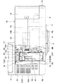
図中、1は建設機械の代表例としての小型な油圧ショベルを示し、この油圧ショベル1の車体は、自走可能なクローラ式の下部走行体2と、該下部走行体2上に旋回可能に搭載された上部旋回体3とにより大略構成されている。そして、上部旋回体3の前部側には作業装置4が俯仰動可能に設けられ、この作業装置4によって土砂の掘削作業等を行うようになっている。
In the figure,
ここで、上部旋回体3は、図2に示すように、下部走行体2の車幅とほぼ等しい左,右方向の幅寸法を有し、上方からみてほぼ円形状に形成されている。これにより、油圧ショベル1は、上部旋回体3が下部走行体2上で旋回したときに、後述するカウンタウエイト7の後面7Dが、ほぼ下部走行体2の車幅内に収まる後方小旋回型の油圧ショベルとして構成されている。
Here, as shown in FIG. 2, the
5は上部旋回体3のベースとなる旋回フレームで、該旋回フレーム5は、図3に示すように、前,後方向に延びる厚肉な鋼板等からなる底板5Aと、該底板5A上に立設され、左,右方向で所定の間隔をもって対面しつつ前,後方向に延びた左,右の縦板5B,5Cと、左縦板5Bの左側に配置され前,後方向に延びた左サイドフレーム5Dと、右縦板5Cの右側に配置され前,後方向に延びた右サイドフレーム5Eと、底板5Aと左,右のサイドフレーム5D,5Eとの間を連結する複数の張出しビーム5Fとにより大略構成され、強固な支持構造体をなしている。
そして、左,右の縦板5B,5Cの前部側には、作業装置4の基端側が回動可能に支持され、左,右の縦板5B,5Cの後部側には、後述のカウンタウエイト7、エンジン8等が取付けられる構成となっている。また、左縦板5Bと左サイドフレーム5Dとの間には、後述のキャブ6を支持するために、前,後方向に離間してキャブ支持枠5Gが設けられている。さらに、キャブ支持枠5Gの後側とカウンタウエイト7との間には、後述の熱交換器20を支持する熱交換器支持台5Hが設けられている。なお、熱交換器20の下側には、鋼板材からなるアンダカバー5Jが設けられ、該アンダカバー5Jにより熱交換器20を保護している。
A base end side of the working
6は旋回フレーム5の前部左側に配設されたキャブで、該キャブ6は、旋回フレーム5のキャブ支持枠5G上に支持され、運転室を画成するものである。そして、キャブ6内には、オペレータが着席する運転席、走行用の操作レバー、作業用の操作レバー等(いずれも図示せず)が配設されている。
7は旋回フレーム5の後端部に設けられたカウンタウエイトで、該カウンタウエイト7は、作業装置4との重量バランスをとるものである。ここで、カウンタウエイト7は、左,右方向の中央部に位置して後述するエンジン8の後側に配置された高さ寸法が大きなウエイト本体部7Aと、ウエイト本体部7Aの左下側から旋回フレーム5の左サイドフレーム5Dに向けて前方に延びる高さ寸法が小さな左前ウエイト部7Bと、ウエイト本体部7Aの右下側から旋回フレーム5の右サイドフレーム5Eに向けて前方に延びる高さ寸法が小さな右前ウエイト部7Cとにより構成されている。従って、カウンタウエイト7は、全体として円弧状をなし中央部が上方に突出した凸形状をなしている。
この場合、カウンタウエイト7の後面7Dは、上部旋回体3が下部走行体2上で旋回したときに、ほぼ下部走行体2の車幅内に収まるように構成されている。このため、カウンタウエイト7は、後述のエンジン8に接近した位置に配設され、カウンタウエイト7は、エンジン8、後述の熱交換器20等に対し、僅かな隙間をもって対向する構成となっている。
In this case, the
8はカウンタウエイト7の前側に搭載されたエンジンで、該エンジン8は、左,右方向に延びる横置き状態に配置され、例えば吸気の流量を増大させる過給機8A(ターボチャージャ)を備えている。また、エンジン8の左側には吸込み式の冷却ファン8Bが設けられ、エンジン8の作動時に冷却ファン8Bが回転駆動されることにより、後述する建屋カバー12内に冷却風が供給される構成となっている。また、冷却ファン8Bの左側には後述の熱交換器20が隣接して配設されている。
一方、エンジン8の右側には、該エンジン8によって駆動される油圧ポンプ9が取付けられ、該油圧ポンプ9は、油圧ショベル1に設けられた各種油圧アクチュエータに向けて作動用の圧油を吐出するものである。そして、これらエンジン8、油圧ポンプ9、熱交換器20等は、旋回フレーム5に搭載される搭載機器を構成し、後述の建屋カバー12内に収容される構成となっている。
On the other hand, a
10は旋回フレーム5の右側で、かつ油圧ポンプ9の前側に位置して配設された燃料タンクで、該燃料タンク10は、エンジン8に供給される燃料を貯溜するものである。11は燃料タンク10の左側に隣接して配設された作動油タンクで、該作動油タンク11は、油圧ショベル1に設けられた油圧アクチュエータに供給される作動油を貯溜するものである。
A
次に、カウンタウエイト7の前側に位置して旋回フレーム5上に配設された建屋カバー12について述べる。
Next, the
即ち、12は建屋カバーを示し、該建屋カバー12は、エンジン8、油圧ポンプ9、後述の熱交換器20等の搭載機器を収容するものである。ここで、建屋カバー12は、後述のエンジンカバー13、左上面カバー16、右上面カバー17、左側面ドア18、右側面ドア19により構成されている。
That is, 12 shows a building cover, and this
13は建屋カバー12の上面側を構成するエンジンカバーで、該エンジンカバー13は、エンジン8、油圧ポンプ9、熱交換器20等の搭載機器を上方および後方から開閉可能に覆うものである。ここで、エンジンカバー13は、搭載機器の上方を覆った状態で左,右方向に延びる上面板13Aと、該上面板13Aの後端側から下向きに折曲げられ、カウンタウエイト7の後面7Dに沿って円弧状に湾曲した後面板13Bとにより大略構成されている。
また、図2に示すように、エンジンカバー13の上面板13Aの前端部13A1は、左,右方向に直線状に延びている。上面板13Aの左端部13A2と右端部13A3は、それぞれ前,後方向に直線状に延び、上面板13Aの後端部13A4は後面板13Bとの境界部をなして円弧状に延びている。
As shown in FIG. 2, the front end 13A1 of the
そして、上面板13Aの前端部13A1は、図6等に示すように、旋回フレーム5上に配設されたサポート部材14に複数のヒンジ15を支点として上,下方向に回動可能に取付けられている。従って、エンジンカバー13は、エンジン8、油圧ポンプ9のメンテナンス作業を行うときに、図1中に実線で示す閉位置と二点鎖線で示す開位置との間で上,下方向に開,閉する構成となっている。また、エンジンカバー13にはロック機構(図示せず)が設けられ、該ロック機構を施錠することにより、エンジンカバー13を閉位置にロックすることができる構成となっている。
As shown in FIG. 6 and the like, the front end 13A1 of the
また、図6に示すように、エンジンカバー13の内側面には、例えばスポンジゴム等により形成された遮蔽部材13Cが固着されている。この遮蔽部材13Cは、後述する熱交換器20の右側(支持枠体21の右側面板21C)の上方で、かつ上面板13Aの前端部13A1と後端部13A4との間を前,後方向に延びて配置されている。これにより、エンジンカバー13を閉位置としたときには、遮蔽部材13Cは後述する仕切部材26の外周縁部に適度な弾性をもって当接することができる。一方、エンジン8の冷却ファン8Bによって建屋カバー12内に吸込まれる冷却風は、熱交換器20を通過することによって高温となる。そこで、前記遮蔽部材13Cは、この高温となった冷却風が熱交換器20の上流側(外気吸込側)に再び廻込むのを阻止するものである。
Further, as shown in FIG. 6, a shielding
16はエンジンカバー13の左側に配設された左上面カバーで、該左上面カバー16は、ほぼ三角形の平板状に形成されている。そして、左上面カバー16は、エンジンカバー13を構成する上面板13Aの左端側13A2に隣接して固定され、エンジンカバー13と一緒に熱交換器20等を上方から覆うものである。
17はエンジンカバー13の右側に配設された右上面カバーで、該右上面カバー17は、ほぼ三角形の平板状に形成されている。そして、右上面カバー17は、エンジンカバー13を構成する上面板13Aの右端側13A3に隣接して固定され、エンジンカバー13と一緒に油圧ポンプ9等を上方から覆うものである。
18は左上面カバー16の下側に位置してカウンタウエイト7とキャブ6との間に配設された左側面ドアで、該左側面ドア18は、熱交換器20等を左側方から開閉可能に覆うものである。また、左側面ドア18には、後述の熱交換器20に向けて建屋カバー12内に冷却風を流入させる多数の流入口18Aが形成されている。
18 is a left side door located below the left
19は右上面カバー17の下側に位置してカウンタウエイト7と燃料タンク10との間に配設された右側面ドアで、該右側面ドア19は、油圧ポンプ9等を右側方から開閉可能に覆うものである。
19 is a right side door located under the right
次に、エンジン8の左側に隣接して旋回フレーム5上に設けられた熱交換器20について述べる。
Next, the
即ち、20は熱交換器を示し、該熱交換器20は、キャブ6とカウンタウエイト7との間に位置し、旋回フレーム5の熱交換器支持台5H上に固定されている。そして、熱交換器20は、エンジン8の冷却ファン8Bによって建屋カバー12内に供給される冷却風により、温度上昇した各種の流体(エンジン冷却水、作動油、圧縮吸気等)を冷却するものである。ここで、熱交換器20は、図5ないし図11に示すように、後述の支持枠体21と、ラジエータ22、オイルクーラ23、インタクーラ24からなる熱交換要素とにより大略構成されている。
That is, 20 indicates a heat exchanger, and the
21は熱交換器20の外殻を構成するために枠構造体からなる支持枠体で、該支持枠体21は前,後方向に長い直方体をなしている。そして、この支持枠体21は、後述のラジエータ22、オイルクーラ23、インタクーラ24からなる熱交換要素を取囲んで支持した状態で、旋回フレーム5の熱交換器支持台5H上に固定されている。
ここで、支持枠体21は、図9に示すように、キャブ6側に配置された前面板21Aと、該前面板21Aと前,後方向で対面しカウンタウエイト7側に配置された後面板21Bと、前面板21Aと後面板21Bとの間を連結しエンジン8と隣接するように該エンジン8に対面して配置された右側面板21Cと、これら前面板21A、後面板21B、右側面板21Cの上端側に設けられ前,後方向に延びた上面板21Dとにより大略構成されている。そして、右側面板21Cの中央部には、大径な通気孔21Eと、該通気孔21Eの外周側からエンジン8側に突出した円筒状のファンシュラウド21Fとが設けられ、このファンシュラウド21Fによってエンジン8の冷却ファン8Bを外周側から取囲む構成となっている。
Here, as shown in FIG. 9, the
22はエンジン8の冷却ファン8Bに対面して支持枠体21に取付けられたラジエータで、該ラジエータ22は、冷却ファン8Bによって建屋カバー12内に吸込まれる冷却風の流れ方向(左,右方向)と対面して配置されている。そして、ラジエータ22は、冷却ファン8Bによって吸込まれる冷却風により、エンジン冷却水の熱を放熱し、エンジン8を冷却するものである。
A
23はラジエータ22の前側に並んで支持枠体21に取付けられたオイルクーラで、該オイルクーラ23は、ラジエータ22と前,後方向で隣接した状態で、かつ建屋カバー12内に吸込まれる冷却風の流れ方向と対面して配置されている。そして、オイルクーラ23は、油圧ショベル1に設けられた各種の油圧アクチュエータから作動油タンク11に戻る作動油の熱を冷却風中に放熱することにより、この作動油を冷却するものである。
An
24はラジエータ22と左,右方向に重なる状態で支持枠体21に取付けられたインタクーラである。即ち、このインタクーラ24は、建屋カバー12内に吸込まれる冷却風の流れ方向に対しラジエータ22の上流側に配置されている。そして、インタクーラ24は、エンジン8の過給機8Aから供給される圧縮吸気の熱を冷却風中に放熱することにより、この圧縮吸気を冷却するものである。
An
25は支持枠体21に対し左,右方向の左側に着脱可能に取付けられた2枚の防塵ネットである。即ち、これら各防塵ネット25は、冷却風の流れ方向に対し、ラジエータ22、オイルクーラ23、インタクーラ24よりも上流側に配置されている。そして、各防塵ネット25は、冷却風に含まれる塵埃を捕捉し、清浄な冷却風を熱交換器20に供給するものである。
次に、エンジン8と熱交換器20との間を仕切る仕切部材26について説明する。
Next, the
即ち、26は熱交換器20に設けられた仕切部材を示している。この仕切部材26は支持枠体21のうちエンジン8と隣接する右側面21Cに取付けられ、その上部側は支持枠体21の上面板21Dよりも上方に延びている。この仕切部材26は、遮蔽部材13Cと協働してエンジン8と熱交換器20との間を仕切ることにより、エンジン8から発生した熱が、熱交換器20に吸込まれる冷却風に伝わるのを阻止するものである。そして、図12および図13に示すように、仕切部材26は、後述の前仕切板27と、後仕切板28と、中間仕切板29とにより構成されている。
That is,
27は熱交換器20を構成する支持枠体21の前部上端側に設けられた前仕切板で、該前仕切板27は、ほぼ正方形をなす平板部27Aと、該平板部27Aの後端部から上方に立上がり左,右方向に延びた前立上り部27Bとを有している。そして、前仕切板27は、オイルクーラ23の上方に配置され、平板部27Aを支持枠体21の前面板21Aにボルト締めすることにより、前立上り部27Bが支持枠体21の上面板21Dから上方(エンジンカバー13側)に突出する構成となっている。
27 is a front partition plate provided on the front upper end side of the
28は支持枠体21の後部上端側に設けられた後仕切板で、該後仕切板28は、全体として上,下方向に延びる平板状に形成され、その前端側が支持枠体21の右側面板21Cにボルト締めされるものである。そして、後仕切板28は、その上部位置28Aが支持枠体21の上面板21Dから上方に突出すると共に、後部位置28Bが支持枠体21の後面板21Bから後方(カウンタウエイト7側)に突出する構成となっている。また、図6、図13等に示すように、後仕切板28の外周縁部には、例えば耐熱性を有するゴム等の弾性材料を用いて形成されたモール28Cが取付けられている。このモール28Cは軟質材料であるから、このモール28Cがエンジンカバー13の内側面に設けられた遮蔽部材13Cと接触しても、当該遮蔽部材13Cが破損するのを防止することができる。
29は支持枠体21の中間部上端側に設けられた中間仕切板で、該中間仕切板29は、前仕切板27と後仕切板28との間を前,後方向に延び、その下端側が支持枠体21の右側面板21Cにボルト締めされるものである。そして、中間仕切板29の上部位置29Aは、前仕切板27の前立上り部27Bの上端と後仕切板28の上部位置28Aとに同じ高さをもって、支持枠体21の上面板21Dから上方に突出する構成となっている。また、中間仕切板29は、エンジンカバー13の遮蔽部材13Cと上,下方向で対向する位置に配置されている。
29 is an intermediate partition plate provided on the upper end side of the intermediate portion of the
このように、仕切部材26を構成する前仕切板27の前立上り部27B、後仕切板28の上部位置28A、中間仕切板29の上部位置29Aが、熱交換器20を構成する支持枠体21の上面板21Dから上方に突出することにより、熱交換器20とエンジン8との間を仕切部材26によって仕切っている。これにより、仕切部材26は、遮蔽部材13Cと協働してエンジン8から発生した熱(熱気)が熱交換器20に伝わるのを阻止することができる構成となっている。
As described above, the
次に、本実施の形態において建屋カバー12内に画成される物品格納空間30および該物品格納空間30内に設けられる箱保持具31について述べる。
Next, the
まず、30は熱交換器20の上面側に位置して建屋カバー12内に画成された物品格納空間で、該物品格納空間30は、後述する物品箱32等の物品を格納するものである。そして、物品格納空間30は、図7、図8に示すように、熱交換器20を構成する支持枠体21の上面板21Dと、仕切部材26のうち支持枠体21の上面板21Dから上方に突出した部位と、エンジンカバー13の上面板13Aの下面とによって囲まれた空間により構成されている。従って、物品格納空間30は、仕切部材26と遮蔽部材13Cによってエンジン8と隔てられると共に、エンジン8の冷却ファン8Bによって建屋カバー12内に吸込まれる冷却風の流れ方向に対し、エンジン8よりも上流側に位置している。また、物品格納空間30は、エンジンカバー13によって開,閉されるものである。
First, 30 is an article storage space located on the upper surface side of the
31は熱交換器20を構成する支持枠体21の上面板21Dのうち物品格納空間30を画成する部位に設けられた前,後一対の箱保持具で、該各箱保持具31は、物品格納空間30内で後述の物品箱32を保持するものである。ここで、図10および図11に示すように、各箱保持具31は、物品箱32を下側から支持する底面31Aと、該底面31Aから上方に立上がり物品箱32を外側から取囲む略U字型の側壁面31Bと、底面31Aから下方に突出した取付板31Cとにより構成されている。
そして、各箱保持具31は、取付板31Cを支持枠体21の上面板21Dにボルト締めすることにより、側壁面31Bが前,後方向に一定の間隔をもって対面した状態で上面板21Dに固定され、後述の物品箱32を前,後方向から挟込むように保持する構成となっている。
Each
32は箱保持具31に保持された状態で物品格納空間30内に収容された物品箱で、該物品箱32は、上面32A、下面32B、および4つの側面32Cによって囲まれた直方体の箱体からなっている。ここで、物品箱32の内部には、例えばエンジン8、熱交換器20等のメンテナンス作業に用いる各種の工具類、交換部品等の物品が収容されている。
そして、物品箱32は、各箱保持具31の底面31A上に下面32Bを載置した状態で、各箱保持具31の側壁面31Bによって外側から取囲まれている。これにより、物品箱32は、締結部材を用いることなく、箱保持具31によって、前,後方向および左,右方向への移動が禁止され、かつ上,下方向への移動が可能な状態に保持されている。
The
この場合、図13に示すように、各箱保持具31の底面31Aから側壁面31Bの上端部までの高さ寸法Aは、箱保持具31によって物品箱32を保持した状態で該物品箱32の上面32Aとエンジンカバー13(上面板13A)の下面との間に形成される隙間寸法Bよりも大きく設定されている(A>B)。
In this case, as shown in FIG. 13, the height dimension A from the
これにより、例えば油圧ショベル1が不整地等を走行するときの振動等により、物品箱32が箱保持具31に対して上,下方向に移動し、物品箱32の上面32Aがエンジンカバー13の下面に衝合したとしても、物品箱32の下端側を箱保持具31の側壁面31Bによって取囲んだ状態を維持することができ、物品箱32が箱保持具31から離脱するのを抑えることができる構成となっている。
As a result, the
本実施の形態による油圧ショベル1は上述の如き構成を有するもので、この油圧ショベル1は、下部走行体2によって作業現場を自走し、上部旋回体3を旋回させつつ作業装置4を用いて土砂の掘削作業等を行う。
The
ここで、油圧ショベル1を用いて掘削作業等を行う前には、通常、建屋カバー12内に収容されたエンジン8、油圧ポンプ9、熱交換器20等の搭載機器について、点検、整備等のメンテナンス作業を行う。
Here, before excavation work or the like is performed using the
この場合、本実施の形態によれば、熱交換器20を構成する支持枠体21の上面板21Dと、エンジン8と熱交換器20との間を仕切る仕切部材26のうち支持枠体21の上面板21Dから上方に突出した部位と、エンジンカバー13の上面板13Aとによって囲まれた空間を物品格納空間30として画成し、この物品格納空間30内に、メンテナンス作業に必要な工具類を入れた物品箱32を収容する構成としている。
In this case, according to the present embodiment, the
このように、建設機械が、エンジン8とカウンタウエイト7とが接近して配置された後方小旋回型の小型な油圧ショベル1の場合であっても、熱交換器20の上面側を有効に利用することにより、建屋カバー12内に物品箱32等の物品を収容するための広いスペースをもった物品格納空間30を確保することができる。
As described above, even when the construction machine is the small
このため、作業者は、エンジンカバー13を図1中の二点鎖線で示す開位置に移動させることにより、物品格納空間30内の物品箱32の出し入れを、広いスペース内で迅速かつ容易に行うことができる。この結果、メンテナンス作業に必要な工具類を迅速に取出すことができ、この点検、整備等のメンテナンス作業の作業性を高めることができる。
For this reason, the operator moves the
この場合、物品格納空間30内に物品箱32を収容したので、例えば各種の工具類や交換部品等の物品を物品箱32内にまとめた状態で、これら物品を、物品箱32ごと物品格納空間30から容易に出し入れすることができる。
In this case, since the
一方、メンテナンス作業が終了して物品箱32を物品格納空間30内に戻した後には、エンジンカバー13に設けられたロック機構(図示せず)を施錠し、エンジンカバー13を閉位置にロックする。これにより、エンジンカバー13によって物品格納空間30を覆い隠すことができるので、物品格納空間30内に収容された物品箱32が盗難されるのを確実に防止することができる。
On the other hand, after the maintenance work is completed and the
さらに、物品格納空間30は、仕切部材26と熱交換器20の上面側とエンジンカバー13の下面とによって囲まれている。また、物品格納空間30は、仕切部材26とエンジンカバー13の遮蔽部材13Cとによってエンジン8と隔てられると共に、建屋カバー12内に供給される冷却風の流れ方向に対し、エンジン8よりも上流側に位置している。このため、物品格納空間30内に収容した物品箱32にエンジン8から発生した熱が伝わるのを抑えることができる。
Further, the
従って、例えば物品箱32内にプラスチック製の部品、工具類を収容した場合に、このプラスチック製の部品が熱による劣化を生じるのを抑えることができる。また、物品箱32が過度に温められることがなく、エンジン8を停止させた直後においても、物品格納空間30内に収容した物品箱32を容易に出し入れすることができる。
Therefore, for example, when plastic parts and tools are accommodated in the
また、本実施の形態によれば、熱交換器20を構成する支持枠体21の上面板21Dのうち、物品格納空間30を画成する部位に箱保持具31を設けることにより、この箱保持具31によって、物品箱32を物品格納空間30内で安定した状態に保持することができる。これにより、油圧ショベル1が不整地走行時や掘削作業時に振動を発生しても、物品箱32が物品格納空間30内を不規則に移動し、物品箱32が熱交換器20の構成部品、仕切部材26に衝突するのを抑えることができる。これにより、物品箱32、熱交換器20、仕切部材26等を、油圧ショベル1が発生する振動に対して保護することができる。
In addition, according to the present embodiment, the
さらに、本実施の形態によれば、箱保持具31の底面31Aから側壁面31Bの上端部までの高さ寸法Aを、箱保持具31によって保持された物品箱32の上面32Aとエンジンカバー13の上面板13Aの下面との間に形成される隙間寸法Bよりも大きく設定したので、物品箱32を箱保持具31によって確実に保持しておくことができる。即ち、例えば油圧ショベル1が不整地等を走行するときの振動により、物品箱32が箱保持具31に対して上,下方向に移動し、物品箱32の上面32Aがエンジンカバー13(上面板13A)の下面に衝合したとしても、物品箱32の下端側を箱保持具31の側壁面31Bによって取囲んでおくことができるので、物品箱32が箱保持具31から離脱するのを抑えることができる。
Further, according to the present embodiment, the height dimension A from the
この結果、物品箱32を締結部材を用いて箱保持具31に固定する必要がなく、エンジンカバー13を開くだけで、物品箱32を箱保持具31から容易に取出すことができるので、該物品箱32内に収容された工具類を用いてエンジン8等の搭載機器に対する点検、整備作業を行うときの作業性を一層高めることができる。
As a result, it is not necessary to fix the
さらにまた、本実施の形態によれば、エンジンカバー13の下面側には、仕切部材26と上,下方向で対面し、かつ前,後方向に延びる遮蔽部材13Cが設けられている。従って、これらの仕切部材26と遮蔽部材13Cとにより、熱交換器20を通過して高温となった冷却風が熱交換器20の上流側に廻込むのを阻止することができる。
Furthermore, according to the present embodiment, the lower surface side of the
なお、上述した実施の形態では、熱交換器20を構成する熱交換要素として、ラジエータ22、オイルクーラ23、インタクーラ24を例示している。しかし、本発明はこれに限るものではなく、例えば空調装置用の冷媒を凝縮するためのコンデンサを熱交換要素として加えてもよい。また、熱交換器20は、ラジエータとオイルクーラとのうち、いずれか一方のみを搭載した形式のものであってもよい。
In the above-described embodiment, the
また、上述した実施の形態では、熱交換器20をエンジン8の左側に配置した場合を例示している。しかし、本発明はこれに限らず、例えば熱交換器をエンジンの右側に配置してもよい。この場合には、エンジンの左側に油圧ポンプを配置する構成となる。
Moreover, in embodiment mentioned above, the case where the
また、上述した実施の形態では、仕切部材26を前仕切板27、後仕切板28、中間仕切板29の3部材によって構成した場合を例示している。しかし、本発明はこれに限るものではなく、例えば単一の部材からなる仕切部材を用いてもよく、2部材、または4部材以上の部材によって仕切部材を構成してもよい。
Moreover, in embodiment mentioned above, the case where the
また、上述した実施の形態では、熱交換器20の支持枠体21の上面板21Dに箱保持具31を設け、この箱保持具31によって物品箱32を物品格納空間30内に保持する構成を例示している。しかし、本発明はこれに限らず、例えば物品箱32を支持枠体21の上面板21D上に直接的に載置する構成としてもよい。
In the above-described embodiment, the
さらに、上述した実施の形態では、建設機械として油圧ショベル1を例に挙げたが、本発明はこれに限るものではなく、例えば油圧クレーン、ホイールローダ等の他の建設機械に広く適用することができる。
Furthermore, in the embodiment described above, the
Claims (7)
前記熱交換器(20)には、前記エンジン(8)と前記熱交換器(20)との間を仕切り該熱交換器(20)の上面よりも上方に延びる仕切部材(26)を設け、
該仕切部材(26)と前記熱交換器(20)の上面側と前記エンジンカバー(13)の下面側とによって囲まれた空間を、物品格納空間(30)として画成する構成としたことを特徴とする建設機械。A counterweight (7) that balances the weight of the self-propelled vehicle body (3) provided with the work device (4) on the front side and the work device (4) provided on the rear side of the vehicle body (3). ), An engine (8) mounted on the vehicle body (3) located on the front side of the counterweight (7), and mounted on the vehicle body (3) adjacent to the engine (8) by cooling air. A heat exchanger (20) that cools the fluid, an engine cover that houses the mounted device including the engine (8) and the heat exchanger (20), and is opened and closed when maintaining the mounted device on the upper surface side. In a construction machine comprising a building cover (12) having (13),
The heat exchanger (20) is provided with a partition member (26) that partitions between the engine (8) and the heat exchanger (20) and extends above the upper surface of the heat exchanger (20),
A space surrounded by the partition member (26), the upper surface side of the heat exchanger (20) and the lower surface side of the engine cover ( 13 ) is defined as an article storage space (30). A featured construction machine.
前記箱保持具(31)の底面(31A)から側壁面(31B)の上端部までの高さ寸法(A)は、前記箱保持具(31)によって前記物品箱(32)を保持した状態で該物品箱(32)の上面(32A)と前記エンジンカバー(13)の下面との間に形成される隙間寸法(B)よりも大きく設定する構成としてなる請求項4に記載の建設機械。The box holder (31) includes a bottom surface (31A) that supports the article box (32) from below, and a side wall surface (31B) that rises from the bottom face (31A) and surrounds the article box (32) from the outside. And
The height dimension (A) from the bottom surface (31A) of the box holder (31) to the upper end of the side wall surface (31B) is the state in which the article box (32) is held by the box holder (31). The construction machine according to claim 4, wherein the construction machine is configured to be larger than a gap dimension (B) formed between an upper surface (32A) of the article box (32) and a lower surface of the engine cover (13).
Priority Applications (1)
| Application Number | Priority Date | Filing Date | Title |
|---|---|---|---|
| JP2010522653A JP4880779B2 (en) | 2008-07-31 | 2009-05-28 | Construction machinery |
Applications Claiming Priority (4)
| Application Number | Priority Date | Filing Date | Title |
|---|---|---|---|
| JP2008197823 | 2008-07-31 | ||
| JP2008197823 | 2008-07-31 | ||
| PCT/JP2009/059778 WO2010013537A1 (en) | 2008-07-31 | 2009-05-28 | Construction machine |
| JP2010522653A JP4880779B2 (en) | 2008-07-31 | 2009-05-28 | Construction machinery |
Publications (2)
| Publication Number | Publication Date |
|---|---|
| JPWO2010013537A1 JPWO2010013537A1 (en) | 2012-01-12 |
| JP4880779B2 true JP4880779B2 (en) | 2012-02-22 |
Family
ID=41610244
Family Applications (1)
| Application Number | Title | Priority Date | Filing Date |
|---|---|---|---|
| JP2010522653A Expired - Fee Related JP4880779B2 (en) | 2008-07-31 | 2009-05-28 | Construction machinery |
Country Status (5)
| Country | Link |
|---|---|
| US (1) | US8365855B2 (en) |
| EP (1) | EP2330253A1 (en) |
| JP (1) | JP4880779B2 (en) |
| CN (1) | CN101952519B (en) |
| WO (1) | WO2010013537A1 (en) |
Families Citing this family (28)
| Publication number | Priority date | Publication date | Assignee | Title |
|---|---|---|---|---|
| JP5118116B2 (en) * | 2009-11-11 | 2013-01-16 | コベルコ建機株式会社 | Construction machinery |
| US9010481B2 (en) * | 2009-11-17 | 2015-04-21 | Stac, Inc. | Self-contained truck mountable hydraulic pumping arrangement |
| DE102010015163A1 (en) * | 2010-04-16 | 2011-10-20 | Liebherr-Hydraulikbagger Gmbh | Construction machine or transhipment device |
| JP2012106836A (en) * | 2010-11-17 | 2012-06-07 | Tcm Corp | Diesel particulate filter mounting structure for industrial vehicle |
| JP5150740B2 (en) * | 2011-01-21 | 2013-02-27 | 株式会社小松製作所 | Work vehicle |
| JP5578114B2 (en) * | 2011-03-04 | 2014-08-27 | コベルコ建機株式会社 | Wiring structure of hybrid construction machine |
| JP5160668B2 (en) * | 2011-06-17 | 2013-03-13 | 株式会社小松製作所 | Excavator |
| JP5864202B2 (en) * | 2011-10-18 | 2016-02-17 | 株式会社Kcm | Industrial vehicle |
| JP5130410B1 (en) * | 2012-07-26 | 2013-01-30 | 株式会社小松製作所 | Work vehicle |
| JP5856920B2 (en) * | 2012-08-06 | 2016-02-10 | 株式会社クボタ | Working machine |
| JP5821872B2 (en) * | 2013-02-22 | 2015-11-24 | コベルコ建機株式会社 | Construction machine intake structure |
| US20150163945A1 (en) | 2013-12-11 | 2015-06-11 | Honeywell International Inc. | Hvac controller with thermistor biased against an outer housing |
| JP6260284B2 (en) * | 2014-01-09 | 2018-01-17 | コベルコ建機株式会社 | Construction machinery side frame |
| JP6005082B2 (en) * | 2014-02-04 | 2016-10-12 | 日立建機株式会社 | Construction machinery |
| US10287967B2 (en) * | 2014-04-30 | 2019-05-14 | Champion Power Equipment, Inc. | Integrated oil cooler for internal combustion engine |
| JP6672087B2 (en) * | 2016-06-21 | 2020-03-25 | 株式会社クボタ | Work machine |
| US10661650B2 (en) * | 2016-07-22 | 2020-05-26 | Nimer Ibrahim Shiheiber | Radiator system |
| JP1606393S (en) * | 2017-08-31 | 2018-06-11 | ||
| JP6962872B2 (en) * | 2018-06-26 | 2021-11-05 | 株式会社日立建機ティエラ | Construction machinery |
| US11413955B2 (en) * | 2018-06-29 | 2022-08-16 | Kubota Corporation | Working machine |
| USD905762S1 (en) * | 2018-10-22 | 2020-12-22 | J.C. Bamford Excavators Limited | Excavator |
| USD896285S1 (en) * | 2018-10-22 | 2020-09-15 | J.C. Bamford Excavators Limited | Excavator |
| USD896284S1 (en) * | 2018-10-22 | 2020-09-15 | J.C. Bamford Excavators Limited | Excavator |
| USD895687S1 (en) * | 2018-10-22 | 2020-09-08 | J.C. Bamford Excavators Limited | Excavator |
| USD977031S1 (en) * | 2018-12-12 | 2023-01-31 | Bruder Spielwaren Gmbh + Co. Kg | Toy |
| JP7082950B2 (en) * | 2019-03-04 | 2022-06-09 | 株式会社日立建機ティエラ | Construction machinery |
| JP7329434B2 (en) * | 2019-12-23 | 2023-08-18 | 株式会社小松製作所 | working machine |
| EP4375428A1 (en) * | 2022-11-25 | 2024-05-29 | Yanmar Holdings Co., Ltd. | Work machine |
Citations (5)
| Publication number | Priority date | Publication date | Assignee | Title |
|---|---|---|---|---|
| JP2000280760A (en) * | 1999-04-01 | 2000-10-10 | Mitsubishi Agricult Mach Co Ltd | Working traveling car |
| JP2002061225A (en) * | 2000-08-15 | 2002-02-28 | Hitachi Constr Mach Co Ltd | Hydraulic backhoe with small slewing radius |
| JP2004003398A (en) * | 2002-05-31 | 2004-01-08 | Shin Caterpillar Mitsubishi Ltd | Construction machine |
| WO2006070733A1 (en) * | 2004-12-27 | 2006-07-06 | Kobelco Construction Machinery Co., Ltd. | Cooling structure of construction machine |
| WO2008065894A1 (en) * | 2006-11-28 | 2008-06-05 | Hitachi Construction Machinery Co., Ltd. | Construction machine |
Family Cites Families (14)
| Publication number | Priority date | Publication date | Assignee | Title |
|---|---|---|---|---|
| US3860090A (en) * | 1973-06-20 | 1975-01-14 | Flanary Ind Inc | Mobile construction machine greasing assembly |
| DE9205323U1 (en) | 1992-04-16 | 1992-06-25 | Herion-Werke Kg, 7012 Fellbach | Device for controlling electrohydraulic valves |
| JP2593645Y2 (en) | 1992-09-30 | 1999-04-12 | 油谷重工株式会社 | Counterweight tool box structure |
| JP3409559B2 (en) | 1996-01-22 | 2003-05-26 | コベルコ建機株式会社 | Floor plate structure of construction machinery |
| US6296436B1 (en) * | 1997-04-08 | 2001-10-02 | Allied Gator, Inc. | Multipurpose counterweight housing and counterweight |
| JP3589575B2 (en) | 1997-09-30 | 2004-11-17 | コベルコ建機株式会社 | Revolving superstructure of construction equipment |
| DE60037740T2 (en) * | 1999-06-25 | 2009-01-15 | Kobelco Construction Machinery Co., Ltd., Hiroshima | HYBRID BUILDING MACHINE AND CONTROL DEVICE FOR THIS CONSTRUCTION MACHINE |
| JP4520649B2 (en) * | 2001-02-06 | 2010-08-11 | 株式会社小松製作所 | Hybrid construction machine |
| JP3956913B2 (en) * | 2003-07-01 | 2007-08-08 | コベルコ建機株式会社 | Work machine |
| JP2006183117A (en) * | 2004-12-28 | 2006-07-13 | Showa Shell Sekiyu Kk | Manufacturing method of ZnO-based transparent conductive film by MOCVD (metal organic chemical vapor deposition) |
| JP4544121B2 (en) * | 2005-09-29 | 2010-09-15 | コベルコ建機株式会社 | Construction machinery |
| US7388301B2 (en) * | 2005-10-12 | 2008-06-17 | Kobelco Construction Machinery Co., Ltd. | Construction machine |
| DE102007023568B3 (en) * | 2007-05-21 | 2008-12-11 | Komatsu Ltd. | Operator seat for a construction machine and thus provided cabin and construction machine |
| CN101668901B (en) * | 2007-08-13 | 2012-05-23 | 日立建机株式会社 | Construction machine |
-
2009
- 2009-05-28 EP EP09802782A patent/EP2330253A1/en not_active Withdrawn
- 2009-05-28 JP JP2010522653A patent/JP4880779B2/en not_active Expired - Fee Related
- 2009-05-28 CN CN2009801058492A patent/CN101952519B/en not_active Expired - Fee Related
- 2009-05-28 WO PCT/JP2009/059778 patent/WO2010013537A1/en active Application Filing
- 2009-05-28 US US12/812,244 patent/US8365855B2/en not_active Expired - Fee Related
Patent Citations (5)
| Publication number | Priority date | Publication date | Assignee | Title |
|---|---|---|---|---|
| JP2000280760A (en) * | 1999-04-01 | 2000-10-10 | Mitsubishi Agricult Mach Co Ltd | Working traveling car |
| JP2002061225A (en) * | 2000-08-15 | 2002-02-28 | Hitachi Constr Mach Co Ltd | Hydraulic backhoe with small slewing radius |
| JP2004003398A (en) * | 2002-05-31 | 2004-01-08 | Shin Caterpillar Mitsubishi Ltd | Construction machine |
| WO2006070733A1 (en) * | 2004-12-27 | 2006-07-06 | Kobelco Construction Machinery Co., Ltd. | Cooling structure of construction machine |
| WO2008065894A1 (en) * | 2006-11-28 | 2008-06-05 | Hitachi Construction Machinery Co., Ltd. | Construction machine |
Also Published As
| Publication number | Publication date |
|---|---|
| JPWO2010013537A1 (en) | 2012-01-12 |
| US8365855B2 (en) | 2013-02-05 |
| CN101952519B (en) | 2012-11-28 |
| EP2330253A1 (en) | 2011-06-08 |
| CN101952519A (en) | 2011-01-19 |
| WO2010013537A1 (en) | 2010-02-04 |
| US20100283278A1 (en) | 2010-11-11 |
Similar Documents
| Publication | Publication Date | Title |
|---|---|---|
| JP4880779B2 (en) | Construction machinery | |
| US8162087B2 (en) | Construction machine | |
| US20100219008A1 (en) | Construction machine | |
| JP4643511B2 (en) | Construction machinery | |
| JP6594968B2 (en) | Work vehicle | |
| JP2010168739A (en) | Construction machinery | |
| JP6495193B2 (en) | Small construction machinery | |
| JP5641983B2 (en) | Work machine battery box | |
| CN104631539A (en) | Construction machine | |
| JP4550476B2 (en) | Construction machinery | |
| JP2004300675A (en) | Working machine | |
| WO2014088033A1 (en) | Construction machine | |
| JP4440730B2 (en) | Construction machinery | |
| JP4430467B2 (en) | Construction machine cooling system | |
| JP5527334B2 (en) | Construction machinery | |
| JP2003268802A (en) | Slewing type working machine | |
| JP5451669B2 (en) | Work machine | |
| JP5567240B1 (en) | Work vehicle | |
| JP2011190566A (en) | Partitioning structure inside engine room | |
| JP6912420B2 (en) | Construction machinery | |
| JP2005282239A (en) | Construction machine | |
| JPH10140613A (en) | Construction equipment | |
| JP5699066B2 (en) | Construction machinery | |
| JP4445681B2 (en) | ROPS cab air conditioner mounting structure | |
| JP2019027197A (en) | Construction machine |
Legal Events
| Date | Code | Title | Description |
|---|---|---|---|
| TRDD | Decision of grant or rejection written | ||
| A01 | Written decision to grant a patent or to grant a registration (utility model) |
Free format text: JAPANESE INTERMEDIATE CODE: A01 Effective date: 20111129 |
|
| A01 | Written decision to grant a patent or to grant a registration (utility model) |
Free format text: JAPANESE INTERMEDIATE CODE: A01 |
|
| A61 | First payment of annual fees (during grant procedure) |
Free format text: JAPANESE INTERMEDIATE CODE: A61 Effective date: 20111201 |
|
| R150 | Certificate of patent or registration of utility model |
Ref document number: 4880779 Country of ref document: JP Free format text: JAPANESE INTERMEDIATE CODE: R150 Free format text: JAPANESE INTERMEDIATE CODE: R150 |
|
| FPAY | Renewal fee payment (event date is renewal date of database) |
Free format text: PAYMENT UNTIL: 20141209 Year of fee payment: 3 |
|
| LAPS | Cancellation because of no payment of annual fees |