JP4873242B2 - Best focus detection method, exposure method, and exposure apparatus - Google Patents
Best focus detection method, exposure method, and exposure apparatus Download PDFInfo
- Publication number
- JP4873242B2 JP4873242B2 JP2006514833A JP2006514833A JP4873242B2 JP 4873242 B2 JP4873242 B2 JP 4873242B2 JP 2006514833 A JP2006514833 A JP 2006514833A JP 2006514833 A JP2006514833 A JP 2006514833A JP 4873242 B2 JP4873242 B2 JP 4873242B2
- Authority
- JP
- Japan
- Prior art keywords
- best focus
- detection method
- data
- focus detection
- optical system
- Prior art date
- Legal status (The legal status is an assumption and is not a legal conclusion. Google has not performed a legal analysis and makes no representation as to the accuracy of the status listed.)
- Expired - Fee Related
Links
- 238000001514 detection method Methods 0.000 title claims description 120
- 238000000034 method Methods 0.000 title claims description 53
- 230000003287 optical effect Effects 0.000 claims description 239
- 238000005259 measurement Methods 0.000 claims description 157
- 238000005286 illumination Methods 0.000 claims description 102
- 230000008859 change Effects 0.000 claims description 66
- 238000005070 sampling Methods 0.000 claims description 35
- 238000012545 processing Methods 0.000 claims description 31
- 230000008569 process Effects 0.000 claims description 24
- 238000006243 chemical reaction Methods 0.000 claims description 16
- 230000010355 oscillation Effects 0.000 claims description 13
- 238000009499 grossing Methods 0.000 claims description 10
- 235000012431 wafers Nutrition 0.000 description 81
- 230000005540 biological transmission Effects 0.000 description 7
- 238000004364 calculation method Methods 0.000 description 7
- 238000004519 manufacturing process Methods 0.000 description 7
- 239000010408 film Substances 0.000 description 6
- 239000011521 glass Substances 0.000 description 6
- 238000003384 imaging method Methods 0.000 description 6
- 239000004065 semiconductor Substances 0.000 description 6
- 241000728904 Iais Species 0.000 description 4
- 238000005452 bending Methods 0.000 description 4
- 238000009826 distribution Methods 0.000 description 4
- VYPSYNLAJGMNEJ-UHFFFAOYSA-N silicon dioxide Inorganic materials O=[Si]=O VYPSYNLAJGMNEJ-UHFFFAOYSA-N 0.000 description 4
- 238000012546 transfer Methods 0.000 description 4
- VYZAMTAEIAYCRO-UHFFFAOYSA-N Chromium Chemical compound [Cr] VYZAMTAEIAYCRO-UHFFFAOYSA-N 0.000 description 3
- 230000001133 acceleration Effects 0.000 description 3
- 230000004075 alteration Effects 0.000 description 3
- 238000011156 evaluation Methods 0.000 description 3
- 238000000691 measurement method Methods 0.000 description 3
- 229920002120 photoresistant polymer Polymers 0.000 description 3
- 230000009467 reduction Effects 0.000 description 3
- 239000000758 substrate Substances 0.000 description 3
- 239000010409 thin film Substances 0.000 description 3
- 238000012935 Averaging Methods 0.000 description 2
- 229910052691 Erbium Inorganic materials 0.000 description 2
- XUIMIQQOPSSXEZ-UHFFFAOYSA-N Silicon Chemical compound [Si] XUIMIQQOPSSXEZ-UHFFFAOYSA-N 0.000 description 2
- 239000003795 chemical substances by application Substances 0.000 description 2
- 229910052804 chromium Inorganic materials 0.000 description 2
- 239000011651 chromium Substances 0.000 description 2
- 238000010586 diagram Methods 0.000 description 2
- 238000006073 displacement reaction Methods 0.000 description 2
- 238000010894 electron beam technology Methods 0.000 description 2
- 230000007613 environmental effect Effects 0.000 description 2
- UYAHIZSMUZPPFV-UHFFFAOYSA-N erbium Chemical compound [Er] UYAHIZSMUZPPFV-UHFFFAOYSA-N 0.000 description 2
- 239000000835 fiber Substances 0.000 description 2
- 230000006870 function Effects 0.000 description 2
- 230000006872 improvement Effects 0.000 description 2
- 239000004973 liquid crystal related substance Substances 0.000 description 2
- 230000000737 periodic effect Effects 0.000 description 2
- 239000010453 quartz Substances 0.000 description 2
- 229910052710 silicon Inorganic materials 0.000 description 2
- 239000010703 silicon Substances 0.000 description 2
- RYGMFSIKBFXOCR-UHFFFAOYSA-N Copper Chemical compound [Cu] RYGMFSIKBFXOCR-UHFFFAOYSA-N 0.000 description 1
- 238000000018 DNA microarray Methods 0.000 description 1
- 229910052769 Ytterbium Inorganic materials 0.000 description 1
- 230000002411 adverse Effects 0.000 description 1
- 229910052782 aluminium Inorganic materials 0.000 description 1
- XAGFODPZIPBFFR-UHFFFAOYSA-N aluminium Chemical compound [Al] XAGFODPZIPBFFR-UHFFFAOYSA-N 0.000 description 1
- 230000015572 biosynthetic process Effects 0.000 description 1
- WUKWITHWXAAZEY-UHFFFAOYSA-L calcium difluoride Chemical compound [F-].[F-].[Ca+2] WUKWITHWXAAZEY-UHFFFAOYSA-L 0.000 description 1
- 239000000919 ceramic Substances 0.000 description 1
- 230000003749 cleanliness Effects 0.000 description 1
- 238000012790 confirmation Methods 0.000 description 1
- 229910052802 copper Inorganic materials 0.000 description 1
- 239000010949 copper Substances 0.000 description 1
- 239000013078 crystal Substances 0.000 description 1
- 230000007423 decrease Effects 0.000 description 1
- 238000013461 design Methods 0.000 description 1
- 238000011161 development Methods 0.000 description 1
- 239000010436 fluorite Substances 0.000 description 1
- 229910052736 halogen Inorganic materials 0.000 description 1
- 150000002367 halogens Chemical class 0.000 description 1
- 238000007654 immersion Methods 0.000 description 1
- 238000007689 inspection Methods 0.000 description 1
- 239000007788 liquid Substances 0.000 description 1
- ORUIBWPALBXDOA-UHFFFAOYSA-L magnesium fluoride Chemical compound [F-].[F-].[Mg+2] ORUIBWPALBXDOA-UHFFFAOYSA-L 0.000 description 1
- 229910001635 magnesium fluoride Inorganic materials 0.000 description 1
- 239000012528 membrane Substances 0.000 description 1
- 230000003340 mental effect Effects 0.000 description 1
- 229910052751 metal Inorganic materials 0.000 description 1
- 239000002184 metal Substances 0.000 description 1
- -1 meteorite Chemical compound 0.000 description 1
- 238000012544 monitoring process Methods 0.000 description 1
- 238000012858 packaging process Methods 0.000 description 1
- 238000000059 patterning Methods 0.000 description 1
- 238000000206 photolithography Methods 0.000 description 1
- 210000001747 pupil Anatomy 0.000 description 1
- 238000005096 rolling process Methods 0.000 description 1
- 229920006395 saturated elastomer Polymers 0.000 description 1
- 239000002210 silicon-based material Substances 0.000 description 1
- XLYOFNOQVPJJNP-UHFFFAOYSA-N water Substances O XLYOFNOQVPJJNP-UHFFFAOYSA-N 0.000 description 1
- NAWDYIZEMPQZHO-UHFFFAOYSA-N ytterbium Chemical compound [Yb] NAWDYIZEMPQZHO-UHFFFAOYSA-N 0.000 description 1
Images


Classifications
-
- G—PHYSICS
- G03—PHOTOGRAPHY; CINEMATOGRAPHY; ANALOGOUS TECHNIQUES USING WAVES OTHER THAN OPTICAL WAVES; ELECTROGRAPHY; HOLOGRAPHY
- G03F—PHOTOMECHANICAL PRODUCTION OF TEXTURED OR PATTERNED SURFACES, e.g. FOR PRINTING, FOR PROCESSING OF SEMICONDUCTOR DEVICES; MATERIALS THEREFOR; ORIGINALS THEREFOR; APPARATUS SPECIALLY ADAPTED THEREFOR
- G03F9/00—Registration or positioning of originals, masks, frames, photographic sheets or textured or patterned surfaces, e.g. automatically
- G03F9/70—Registration or positioning of originals, masks, frames, photographic sheets or textured or patterned surfaces, e.g. automatically for microlithography
- G03F9/7003—Alignment type or strategy, e.g. leveling, global alignment
- G03F9/7023—Aligning or positioning in direction perpendicular to substrate surface
- G03F9/7026—Focusing
-
- G—PHYSICS
- G03—PHOTOGRAPHY; CINEMATOGRAPHY; ANALOGOUS TECHNIQUES USING WAVES OTHER THAN OPTICAL WAVES; ELECTROGRAPHY; HOLOGRAPHY
- G03F—PHOTOMECHANICAL PRODUCTION OF TEXTURED OR PATTERNED SURFACES, e.g. FOR PRINTING, FOR PROCESSING OF SEMICONDUCTOR DEVICES; MATERIALS THEREFOR; ORIGINALS THEREFOR; APPARATUS SPECIALLY ADAPTED THEREFOR
- G03F9/00—Registration or positioning of originals, masks, frames, photographic sheets or textured or patterned surfaces, e.g. automatically
- G03F9/70—Registration or positioning of originals, masks, frames, photographic sheets or textured or patterned surfaces, e.g. automatically for microlithography
- G03F9/7088—Alignment mark detection, e.g. TTR, TTL, off-axis detection, array detector, video detection
Landscapes
- Physics & Mathematics (AREA)
- General Physics & Mathematics (AREA)
- Engineering & Computer Science (AREA)
- Multimedia (AREA)
- Exposure And Positioning Against Photoresist Photosensitive Materials (AREA)
- Length Measuring Devices By Optical Means (AREA)
Description
本発明は、ベストフォーカス検出方法及び露光方法、並びに露光装置に係り、更に詳しくは、投影光学系のベストフォーカス位置を検出するベストフォーカス検出方法及び該ベストフォーカス検出方法を利用する露光方法、並びに前記ベストフォーカス検出方法の実施に好適な露光装置に関する。 The present invention relates to a best focus detection method, an exposure method, and an exposure apparatus. More specifically, the present invention relates to a best focus detection method for detecting a best focus position of a projection optical system, an exposure method using the best focus detection method, and the aforementioned The present invention relates to an exposure apparatus suitable for carrying out a best focus detection method.
従来より、半導体素子又は液晶表示素子等をフォトリソグラフィ工程で製造する際に、フォトマスク又はレチクル(以下、「レチクル」と総称する)のパターンを、投影光学系を介して表面にフォトレジスト等の感光剤が塗布されたウエハ又はガラスプレート等の物体(以下、「ウエハ」と総称する)上に転写する投影露光装置、例えばステップ・アンド・リピート方式の縮小投影露光装置(いわゆるステッパ)や、ステップ・アンド・スキャン方式の走査型投影露光装置(いわゆるスキャニング・ステッパ(スキャナとも呼ばれる))等の逐次移動型の投影露光装置が用いられている。 Conventionally, when a semiconductor element or a liquid crystal display element or the like is manufactured by a photolithography process, a pattern of a photomask or a reticle (hereinafter, collectively referred to as “reticle”) is formed on the surface of a photoresist or the like via a projection optical system. A projection exposure apparatus that transfers onto a wafer or a glass plate or other object (hereinafter referred to as “wafer”) coated with a photosensitive agent, such as a step-and-repeat reduction projection exposure apparatus (so-called stepper), step A sequential movement type projection exposure apparatus such as an AND-scan type scanning projection exposure apparatus (so-called scanning stepper (also called a scanner)) is used.
この種の投影露光装置を用いて露光を行う際には、デフォーカスに起因する露光不良の発生を極力抑制するために、投影光学系の光軸方向に関するウエハの位置を、焦点位置検出系(フォーカス検出系)により検出し、その検出結果に基づいて、ウエハ上の被露光領域(露光光が照射される領域)を投影光学系の最良結像面に一致させる(焦点深度の範囲内に位置させる)必要がある。このためには、投影光学系の最良結像面ないしはベストフォーカス位置を精度良く検出するとともに、その検出結果に基づいて上述の焦点位置検出系(フォーカス検出系)のキャリブレーション、すなわち検出原点の調整又は検出オフセットの調整を行うことが重要である。 When performing exposure using this type of projection exposure apparatus, the position of the wafer with respect to the optical axis direction of the projection optical system is changed to a focal position detection system (in order to suppress exposure failures due to defocusing as much as possible. Based on the detection result, the exposure area on the wafer (area where the exposure light is irradiated) is matched with the best imaging plane of the projection optical system (positioned within the depth of focus range). Need to be). For this purpose, the best imaging plane or the best focus position of the projection optical system is detected with high accuracy, and the above-described focus position detection system (focus detection system) is calibrated based on the detection result, that is, the detection origin is adjusted. Alternatively, it is important to adjust the detection offset.
投影光学系のベストフォーカス位置の検出方法としては、投影光学系の光軸方向に関する異なる位置で、計測用レチクルに形成された計測用マークを投影光学系を介してウエハ上の異なる位置に転写し、そのウエハに形成されたマークの転写像の形成状態に基づいて投影光学系のベストフォーカス位置を検出する方法(焼付け法)と、実際の露光を行うことなく、投影光学系の像面側に配置されるウエハステージ上に空間像計測装置を設け、この空間像計測装置により前述の計測用マークの投影像(空間像)の光強度を検出することで、その検出結果に基づいて投影光学系のベストフォーカス位置を検出する方法(空間像計測法)とが知られている。ここで、空間像計測装置とは、ウエハが載置されるウエハステージ上に設けられ、所定形状の開口パターンが形成されたパターン板と、該パターン板を介した光を受光する受光系とを有する装置の総称である。 As a method for detecting the best focus position of the projection optical system, the measurement marks formed on the measurement reticle are transferred to different positions on the wafer through the projection optical system at different positions in the optical axis direction of the projection optical system. A method of detecting the best focus position of the projection optical system based on the formation state of the transfer image of the mark formed on the wafer (printing method) and the image plane side of the projection optical system without performing actual exposure An aerial image measurement device is provided on the wafer stage to be arranged, and the light intensity of the projection image (aerial image) of the measurement mark described above is detected by the aerial image measurement device. A method of detecting the best focus position (aerial image measurement method) is known. Here, the aerial image measurement device includes a pattern plate that is provided on a wafer stage on which a wafer is placed and on which an opening pattern of a predetermined shape is formed, and a light receiving system that receives light via the pattern plate. It is a general term for devices that have the
空間像計測法による、従来のベストフォーカス位置の検出は、大略次のa.〜d.のような手順で行われていた(特許文献1、2、3等参照)。 The conventional best focus position detection by the aerial image measurement method is generally performed by the following a. ~ D. (See Patent Documents 1, 2, 3, etc.).
a. 計測用マーク(例えばラインアンドスペースパターンから成るマークとする)が形成され、投影光学系の物体面に配置されたレチクルなどを照明光により照明し、前記計測用マークの像を投影光学系により像面に投影した状態で、その投影像に対してパターン板が走査されるように、ウエハステージを投影光学系の光軸に直交する2次元面内で所定方向に移動し、その移動中にパターン板を介した光を受光系により受光して計測用マークの空間像を計測する。
b. 上記a.のような空間像計測を、投影光学系の光軸方向に関する複数の位置(以下、便宜上「Z位置」と呼ぶ)で繰り返す。
c.そして、各Z位置での空間像の光強度信号波形をそれぞれフーリエ変換し、各Z位置での空間像の光強度信号波形から得られる例えばコントラスト(一次周波数成分と直流成分との振幅比)などの所定の情報をそれぞれ求める。
d. そして、Z位置を横軸としコントラスト値を縦軸とする直交座標系上に、上記c.の結果として得られた複数点(例えば15点)の座標位置(Z位置、コントラスト値)をプロットし、これら複数点を最小自乗近似して得られる近似曲線に基づいてベストフォーカス位置を検出する。a. A measurement mark (for example, a mark composed of a line and space pattern) is formed, a reticle placed on the object plane of the projection optical system is illuminated with illumination light, and an image of the measurement mark is imaged by the projection optical system. The wafer stage is moved in a predetermined direction within a two-dimensional plane perpendicular to the optical axis of the projection optical system so that the pattern plate is scanned with respect to the projected image in the projected state on the surface, and the pattern is moved during the movement. The light passing through the plate is received by the light receiving system, and the aerial image of the measurement mark is measured.
b. A. Such aerial image measurement is repeated at a plurality of positions (hereinafter referred to as “Z positions” for convenience) in the optical axis direction of the projection optical system.
c. Then, the light intensity signal waveform of the aerial image at each Z position is Fourier transformed, for example, contrast (amplitude ratio between primary frequency component and DC component) obtained from the light intensity signal waveform of the aerial image at each Z position, etc. Each predetermined information is obtained.
d. Then, on the orthogonal coordinate system having the Z position as the horizontal axis and the contrast value as the vertical axis, the above c. The coordinate positions (Z position, contrast value) of a plurality of points (for example, 15 points) obtained as a result of the above are plotted, and the best focus position is detected based on an approximate curve obtained by least square approximation of these points.
しかしながら、上記従来の空間像計測法によるベストフォーカス検出方法にあっては、上の説明からもわかるように、投影光学系の光軸方向に関してパターン板(ウエハステージ)の位置を、多段階で変更し、かつ各位置で、ウエハステージ(パターン板)を、空間像に対して走査する動作が必要不可欠であることから、必然的に計測に長時間を要していた。かかる不都合を改善するための方法として、上述のステップ数を削減することが考えられるが、このようにすると、ベストフォーカス位置の検出精度が低下してしまう。 However, in the best focus detection method based on the conventional aerial image measurement method, as can be seen from the above description, the position of the pattern plate (wafer stage) is changed in multiple steps with respect to the optical axis direction of the projection optical system. However, since the operation of scanning the wafer stage (pattern plate) with respect to the aerial image is indispensable at each position, the measurement inevitably takes a long time. As a method for improving such an inconvenience, it is conceivable to reduce the number of steps described above. However, in this case, the detection accuracy of the best focus position is lowered.
本発明は、上述した事情の下になされたものであり、第1の観点からすると、第1面上に配置されたパターンの像を第2面上に形成する投影光学系のベストフォーカス位置を検出するベストフォーカス検出方法であって、所定の発振周波数でパルス発振される照明光により前記第1面上に配置されたマークを照明しつつ、前記第2面の近傍で、かつ前記投影光学系の光軸に直交する2次元面内で、前記投影光学系によって形成された前記マークの像に対して開口パターンが形成されたパターン板を所定の計測方向に走査し、該走査中に前記開口パターンを介した前記照明光を受光して、前記計測方向に関する前記マークの像の中心位置の情報を検出する第1工程と;前記マークの像の中心位置の情報に基づいて、前記パターン板を位置決めし、前記照明光により前記第1面上に配置されたマークを照明しつつ、前記パターン板を前記光軸方向に移動させ、その移動中に、前記発振周波数に基づいて設定されたサンプリング間隔で、前記パターン板の前記光軸方向に関する位置データ及び前記照明光の強度データを取得する第2工程と;取得した位置データと、取得した強度データとに基づいて、前記投影光学系のベストフォーカス位置を算出する第3工程と;を含むベストフォーカス検出方法である。 The present invention has been made under the circumstances described above. From the first viewpoint, the best focus position of the projection optical system for forming the image of the pattern arranged on the first surface on the second surface is determined. A best focus detection method for detecting, wherein the projection optical system is in the vicinity of the second surface while illuminating a mark disposed on the first surface with illumination light pulse-oscillated at a predetermined oscillation frequency. A pattern plate on which an aperture pattern is formed is scanned in a predetermined measurement direction with respect to the image of the mark formed by the projection optical system within a two-dimensional plane orthogonal to the optical axis of the aperture, and the aperture is scanned during the scanning. A first step of receiving the illumination light via a pattern and detecting information on a center position of the mark image with respect to the measurement direction; and, based on information on a center position of the mark image, Positioning While illuminating the mark disposed on the first surface by the illumination light, moving the pattern plate to the optical axis direction, during the movement, at a set sampling interval based on the oscillation frequency, the A second step of acquiring position data of the pattern plate in the optical axis direction and intensity data of the illumination light; and calculating a best focus position of the projection optical system based on the acquired position data and the acquired intensity data A best focus detection method comprising: a third step;
これによれば、所定の発振周波数でパルス発振される照明光により第1面上に配置されたマークを照明しつつ、第2面の近傍の投影光学系の光軸に直交する2次元面内で投影光学系によるマークの像(空間像)に対してパターン板を所定の計測方向に走査し、該走査中にパターン板に形成された開口パターンを介した照明光を受光することにより、計測方向に関するマークの像の中心位置の情報を検出する。次いで検出されたマークの像の中心位置の情報に基づいて、パターン板を位置決めした状態で、照明光により前記マークを照明しつつ、パターン板を投影光学系の光軸方向に移動させ、その移動中に、前記発振周波数に基づいて設定されたサンプリング間隔で、パターン板の前記光軸方向に関する位置データ及び照明光の強度データを取得する。この場合、パターン板を前記光軸方向に連続移動させながら前記各データの取得が可能である。 According to this, in a two-dimensional plane orthogonal to the optical axis of the projection optical system in the vicinity of the second surface while illuminating the mark disposed on the first surface with illumination light pulse-oscillated at a predetermined oscillation frequency Measurement is performed by scanning the pattern plate in a predetermined measurement direction with respect to the mark image (aerial image) by the projection optical system and receiving illumination light through the aperture pattern formed on the pattern plate during the scanning. Information on the center position of the mark image with respect to the direction is detected. Next, based on the information on the center position of the detected mark image, the pattern plate is moved in the optical axis direction of the projection optical system while illuminating the mark with illumination light while the pattern plate is positioned. The position data and the intensity data of the illumination light of the pattern plate are acquired at a sampling interval set based on the oscillation frequency . In this case, each data can be acquired while continuously moving the pattern plate in the optical axis direction.
そして、上述のようにして取得した位置データと、強度データとに基づいて、投影光学系のベストフォーカス位置を算出する。 Then, the best focus position of the projection optical system is calculated based on the position data and intensity data acquired as described above.
このように、本発明のベストフォーカス検出方法では、投影光学系の光軸に直交する2次元面内でのパターン板の1回の走査と、その走査後における投影光学系の光軸方向に関するパターン板の1回の走査との組み合わせによって、投影光学系のベストフォーカス位置を算出するためのデータの取得が可能となる。従って、前述の従来例のように、パターン板を光軸方向に関して多数の位置に変化させ、しかも各位置でパターン板を走査させる必要がないので、格段に計測時間を短縮することが可能である。また、上記のサンプリング間隔を可能な範囲で細かく設定することにより、多くのデータを取得可能であることから、ベストフォーカス位置の検出精度(検出分解能)の向上も期待される。 As described above, in the best focus detection method of the present invention, the pattern plate is scanned once in a two-dimensional plane orthogonal to the optical axis of the projection optical system, and the pattern related to the optical axis direction of the projection optical system after the scan. Data for calculating the best focus position of the projection optical system can be acquired in combination with a single scan of the plate. Therefore, unlike the above-described conventional example, it is not necessary to change the pattern plate to a large number of positions in the optical axis direction and to scan the pattern plate at each position, so that the measurement time can be significantly shortened. . Further, since a large amount of data can be acquired by setting the sampling interval as fine as possible, an improvement in detection accuracy (detection resolution) of the best focus position is expected.
この場合において、前記第3工程では、移動平均を用いて前記複数の位置データ及び複数の強度データの少なくとも一方の平滑化を少なくとも一回行い、平滑化後の両方のデータ、又は平滑化後の一方のデータ及び平滑化されていない他方のデータを用いて前記パターン板の前記光軸方向の位置に対する前記照明光の強度の変化曲線を算出し、その変化曲線に基づいて前記ベストフォーカス位置を算出することとすることができる。かかる場合には、上記平滑化によりノイズ成分の影響を低減することができる結果、ベストフォーカス位置の検出精度を向上させることが可能となる。 In this case, in the third step, at least one of the plurality of position data and the plurality of intensity data is smoothed at least once using a moving average, both the smoothed data, or the smoothed data Using one data and the other non-smoothed data, calculate a change curve of the intensity of the illumination light with respect to the position of the pattern plate in the optical axis direction, and calculate the best focus position based on the change curve You can do that. In such a case, the influence of the noise component can be reduced by the smoothing, and as a result, the best focus position detection accuracy can be improved.
本発明は、第2の観点からすると、投影光学系を介して物体上に所定のパターンを形成する露光方法であって、本発明のベストフォーカス検出方法を用いて、前記投影光学系のベストフォーカス位置を検出する検出工程と;前記ベストフォーカス位置の検出結果を利用して前記投影光学系の光軸方向に関する前記物体の位置を調整し、前記パターンを前記投影光学系を介して前記物体上に形成する露光工程と;を含む露光方法である。 According to a second aspect of the present invention, there is provided an exposure method for forming a predetermined pattern on an object via a projection optical system, the best focus of the projection optical system using the best focus detection method of the present invention. A detection step of detecting a position; adjusting a position of the object with respect to an optical axis direction of the projection optical system using a detection result of the best focus position; and placing the pattern on the object via the projection optical system. And an exposure step for forming the exposure method.
これによれば、本発明のベストフォーカス検出方法を用いて、投影光学系のベストフォーカス位置を検出し(検出工程)、該検出工程の検出結果を利用して、投影光学系の光軸方向に関する物体の位置を調整し、パターンを投影光学系を介して光軸方向に関する位置が調整された物体上に形成する(露光工程)。従って、検出工程の処理が短時間で行われることから、検出工程及び露光工程を含む全工程のスループットの向上を図ることが可能である。また、前述の如く、投影光学系のベストフォーカス位置を検出精度の向上も可能であることから、結果的にデフォーカスによる露光不良の殆どない、パターンの物体上での高精度な形成が可能となる。 According to this, the best focus detection method of the present invention is used to detect the best focus position of the projection optical system (detection step), and the detection result of the detection step is used to relate to the optical axis direction of the projection optical system. The position of the object is adjusted, and a pattern is formed on the object whose position in the optical axis direction is adjusted via the projection optical system (exposure process). Accordingly, since the detection process is performed in a short time, it is possible to improve the throughput of all processes including the detection process and the exposure process. In addition, as described above, it is possible to improve the detection accuracy of the best focus position of the projection optical system. As a result, it is possible to form a pattern on the object with almost no exposure failure due to defocusing. Become.
本発明は第3の観点からすると、第1面上に配置されたパターンを投影光学系を用いて、第2面上に配置された物体上に形成する露光装置であって、開口パターンが設けられた移動体と;前記移動体を前記投影光学系の光軸方向及びこれに直交する2次元面内方向に駆動する駆動系と;前記移動体に設けられた開口パターンを介し、所定の発振周波数でパルス発振される照明光を受光する受光素子を含むセンサ部と;前記第1面上に配置されたマークを前記照明光により照明する照明系と;前記マークを照明系からの前記照明光により照明しつつ、前記投影光学系によって形成された前記マークの像に対して、前記第2面の近傍の前記2次元面内で、前記開口パターンが所定の計測方向に走査されるように、前記駆動系を介して前記移動体を前記計測方向に走査駆動し、該走査駆動中に前記センサ部の前記受光素子からの出力信号に基づいて前記計測方向に関する前記マークの像の中心位置の情報を検出する第1の処理装置と;前記マークの像の中心位置の情報に基づいて前記移動体を位置決めし、前記照明系からの前記照明光により前記第1面上に配置された前記マークを照明しつつ、前記駆動系を介して前記移動体を前記光軸方向に移動し、その移動中に、前記発振周波数に基づいて設定されたサンプリング間隔で、前記移動体の前記光軸方向に関する位置データ及び前記照明光の強度データを取得する第2の処理装置と;前記第2の処理装置が取得した前記位置データと、前記第2の処理装置が取得した前記強度データとに基づいて、前記投影光学系のベストフォーカス位置を算出する演算装置と;を備える露光装置である。 According to a third aspect of the present invention, there is provided an exposure apparatus for forming a pattern arranged on a first surface on an object arranged on a second surface using a projection optical system, wherein an opening pattern is provided. A driving system for driving the moving body in an optical axis direction of the projection optical system and a two-dimensional in-plane direction orthogonal to the projection optical system; a predetermined oscillation via an opening pattern provided in the moving body A sensor unit including a light receiving element that receives illumination light pulse-oscillated at a frequency ; an illumination system that illuminates the mark disposed on the first surface with the illumination light ; and the illumination light from the illumination system. The aperture pattern is scanned in a predetermined measurement direction in the two-dimensional plane in the vicinity of the second surface with respect to the image of the mark formed by the projection optical system while illuminating by The moving body is moved through the drive system. A first processing device that scans in the measurement direction and detects information on the center position of the mark image in the measurement direction based on an output signal from the light receiving element of the sensor unit during the scan drive; the movable body is positioned on the basis of the information of the center position of the image of the mark, while illuminating the mark disposed on the first surface by the illumination light from the illumination system, through the drive system The moving body is moved in the optical axis direction, and during the movement, position data regarding the optical axis direction of the moving body and intensity data of the illumination light are obtained at a sampling interval set based on the oscillation frequency. A best focus position of the projection optical system based on the position data acquired by the second processing apparatus and the intensity data acquired by the second processing apparatus. Calculated to the arithmetic unit; an exposure device comprising a.
これによれば、第1の処理装置が、第1面上に配置されたマークを照明系からの所定の発振周波数でパルス発振される照明光により照明しつつ、投影光学系によるマークの像に対して、第2面の近傍で移動体に設けられた所定の開口パターンが2次元面内の所定の計測方向に走査されるように、駆動系を介して移動体を前記計測方向に走査駆動し、該走査駆動中にセンサ部の受光素子からの出力信号に基づいて計測方向に関するマークの像の中心位置の情報を検出する。そして、第2の処理装置は、第1の処理装置により検出されたマークの像の中心位置の情報に基づいて移動体を位置決めした状態で、照明系からの照明光により第1面上に配置されたマークを照明しつつ、駆動系を介して移動体を光軸方向に移動し、その移動中に、前記発振周波数に基づいて設定されたサンプリング間隔で、前記移動体の前記光軸方向に関する位置データ及び前記照明光の強度データを取得する。この場合、第2の処理装置は、パターン板を前記光軸方向に連続移動させながら前記各データの取得が可能である。 According to this, the first processing apparatus illuminates the mark arranged on the first surface with the illumination light pulse-oscillated at a predetermined oscillation frequency from the illumination system, and converts the mark into an image of the mark by the projection optical system. On the other hand, the movable body is scan-driven in the measurement direction via the drive system so that the predetermined opening pattern provided in the movable body in the vicinity of the second surface is scanned in the predetermined measurement direction in the two-dimensional plane. During the scanning drive, information on the center position of the mark image in the measurement direction is detected based on the output signal from the light receiving element of the sensor unit. The second processing device is arranged on the first surface by the illumination light from the illumination system in a state where the moving body is positioned based on the information on the center position of the mark image detected by the first processing device. The moving body is moved in the optical axis direction via the drive system while illuminating the mark, and the moving body is related to the optical axis direction of the moving body at the sampling interval set based on the oscillation frequency during the movement. Position data and intensity data of the illumination light are acquired. In this case, the second processing apparatus can acquire the data while continuously moving the pattern plate in the optical axis direction.
そして、演算装置が、第2の処理装置が上述のようにして取得した位置データと、第2の処理装置が取得した強度データとに基づいて、投影光学系のベストフォーカス位置を算出する。 Then, the arithmetic device calculates the best focus position of the projection optical system based on the position data acquired by the second processing device as described above and the intensity data acquired by the second processing device.
このように、本発明の露光装置では、第1の処理装置による、投影光学系の光軸に直交する2次元面内での移動体(パターン板)の1回の走査と、その走査後における、第2の処理装置による移動体(パターン板)の投影光学系の光軸方向に関する1回の走査との組み合わせによって、投影光学系のベストフォーカス位置を算出するためのデータの取得が可能となる。従って、前述の従来例のように、パターン板を光軸方向に関して多数の位置に変化させ、しかも各位置でパターン板を走査させる必要がないので、格段計測時間を短縮することが可能である。また、上記のサンプリング間隔を可能な範囲で細かく設定することにより、第2の処理装置は、多くのデータを取得可能であることから、この取得したデータに基づいて演算装置により算出されるベストフォーカス位置の算出精度(検出分解能)が向上することも期待される。 As described above, in the exposure apparatus of the present invention, the first processing apparatus performs one scan of the moving body (pattern plate) in the two-dimensional plane orthogonal to the optical axis of the projection optical system, and after the scan. The data for calculating the best focus position of the projection optical system can be obtained by combining the second processing apparatus with the single scanning of the movable body (pattern plate) in the optical axis direction of the projection optical system. . Therefore, unlike the above-described conventional example, it is not necessary to change the pattern plate to a large number of positions in the optical axis direction and to scan the pattern plate at each position, so that it is possible to significantly reduce the measurement time. Further, by setting the sampling interval as fine as possible, the second processing apparatus can acquire a large amount of data. Therefore, the best focus calculated by the arithmetic unit based on the acquired data is obtained. It is expected that the position calculation accuracy (detection resolution) will be improved.
また、演算装置で算出された投影光学系のベストフォーカス位置に基づいて、投影光学系の光軸方向に関する物体の位置を調整し、パターンを投影光学系を介して物体上に形成するようにすることで、デフォーカスによる露光不良の殆どない、パターンの物体上での高精度な形成が可能となる。 Further, the position of the object with respect to the optical axis direction of the projection optical system is adjusted based on the best focus position of the projection optical system calculated by the arithmetic device, and the pattern is formed on the object via the projection optical system. As a result, it is possible to form a pattern with high accuracy on an object with almost no exposure failure due to defocusing.
以下、本発明の一実施形態を図1〜図11に基づいて説明する。 Hereinafter, an embodiment of the present invention will be described with reference to FIGS.
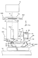
図1には、一実施形態に係る露光装置100の概略的な構成が示されている。この露光装置100は、ステップ・アンド・スキャン方式の走査型投影露光装置、すなわち、いわゆるスキャニング・ステッパ(スキャナとも呼ばれる)である。
FIG. 1 shows a schematic configuration of an
この露光装置100は、光源及び照明光学系(いずれも不図示)を含む照明系10、レチクルRが載置されるレチクルステージRST、投影光学系PL、ウエハWが載置されるウエハステージWST、及びこれらを制御する制御系等を備えている。また、上記各構成部分のうち、光源及び制御系の一部以外の部分は、実際には、内部の温度、圧力等の環境条件がほぼ一定に維持された不図示の環境制御チャンバ(エンバイロンメンタル・チャンバ)内に収容されている。
The
前記照明系10は、例えば特開2001−313250号公報及びこれに対応する米国特許出願公開第2003/0025890号明細書などに開示されるように、光源、オプティカルインテグレータ(ホモジナイザ)等を含む照度均一化光学系、ビームスプリッタ、リレーレンズ、可変NDフィルタ、レチクルブラインド等(いずれも不図示)を含む。この照明系10では、レチクルブラインドで規定されたレチクルR上のスリット状の照明領域を照明光(露光光)ILによりほぼ均一な照度で照明する。ここで、光源としては、一例として波長193nmの真空紫外域のパルスレーザ光を出力する(発振する)ArFエキシマレーザが用いられている。また、オプティカルインテグレータとしては、フライアイレンズ、ロッドインテグレータ(内面反射型インテグレータ)あるいは回折光学素子などを用いることができる。なお、照明系を、例えば特開平6−349701号公報及びこれに対応する米国特許第5,534,970号などに開示されるような照明系と同様に構成しても良い。本国際出願で指定した指定国(又は選択した選択国)の国内法令が許す限りにおいて、上記各公報及び対応する米国特許出願公開明細書又は米国特許における開示を援用して本明細書の記載の一部とする。
The
前記レチクルステージRST上には、回路パターンなどがそのパターン面(図1における下面)に形成されたレチクルRが載置され、例えば真空吸着(又は静電吸着)により固定されている。このレチクルステージRSTは、例えばリニアモータ等を含むレチクルステージ駆動系56Rにより、XY平面内で2次元的に(X軸方向及びこれに直交するY軸方向及びXY平面に直交するZ軸回りの回転方向(θz方向)に)微少駆動可能であるとともに、不図示のレチクルベース上を所定の走査方向(ここでは、図1における紙面直交方向であるY軸方向とする)に指定された走査速度で駆動可能となっている。
On reticle stage RST, reticle R on which a circuit pattern or the like is formed on its pattern surface (the lower surface in FIG. 1) is placed and fixed, for example, by vacuum suction (or electrostatic suction). This reticle stage RST is two-dimensionally (rotated about the X-axis direction and the Y-axis direction perpendicular thereto and the Z-axis perpendicular to the XY plane) in the XY plane by a reticle
レチクルステージRST上には、移動鏡52Rが固定され、レチクルステージRSTのXY面内の位置が、その移動鏡52Rを介してレチクルレーザ干渉計(以下、「レチクル干渉計」という)54Rによって、例えば0.5〜1nm程度の分解能で常時検出される。ここで、実際には、レチクルステージRST上には走査露光時の走査方向(Y軸方向)に直交する反射面を有するY移動鏡と非走査方向(X軸方向)に直交する反射面を有するX移動鏡とが設けられ、これらの移動鏡に対応してレチクルY干渉計とレチクルX干渉計とが設けられているが、図1ではこれらが代表的に移動鏡52R、レチクル干渉計54Rとして示されている。なお、例えば、レチクルステージRSTの端面を鏡面加工して反射面(上述のX移動鏡、Y移動鏡の反射面に相当)を形成しても良い。また、レチクルステージRSTの走査方向(本実施形態ではY軸方向)の位置検出に用いられるX軸方向に伸びた反射面の代わりに、少なくとも1つのコーナーキューブ型ミラー(例えばレトロリフレクタ)を用いても良い。ここで、レチクルY干渉計とレチクルX干渉計の一方、例えばレチクルY干渉計は、測長軸を2軸有する2軸干渉計であり、このレチクルY干渉計の計測値に基づきレチクルステージRSTのY位置に加え、Z軸回りの回転方向(θz方向)の回転も計測できる。
A
レチクル干渉計54RからのレチクルステージRSTの位置情報(又は速度情報)は、ステージ制御装置70、及びこれを介して主制御装置50に送られる。ステージ制御装置70は、主制御装置50の指示に基づいて、レチクルステージ駆動系56Rを介してレチクルステージRSTの移動を制御する。
Position information (or velocity information) of reticle stage RST from
前記投影光学系PLは、その光軸AXの方向をZ軸方向とし、レチクルステージRSTの図1における下方に配置されている。投影光学系PLは、ここでは両側テレセントリックな縮小系であり、光軸AX方向に沿って所定間隔で配置された複数枚のレンズエレメントを含む屈折光学系が使用されている。この投影光学系PLの投影倍率は、例えば1/4又は1/5等である。このため、照明系10からの照明光ILによってレチクルR上でX軸方向に細長く伸びるスリット状又は円弧状の照明領域(前述のレチクルブラインドで規定される)が照明されると、このレチクルRを通過した照明光ILにより、投影光学系PLを介してその照明領域内の回路パターンの縮小像(部分倒立像)が、表面にフォトレジスト(感光剤)が塗布されたウエハW上の前記照明領域と共役な照明光ILの投射領域(以下、「露光領域」とも呼ぶ)に形成される。
The projection optical system PL is disposed below the reticle stage RST in FIG. 1 with the direction of the optical axis AX as the Z-axis direction. Here, the projection optical system PL is a double-sided telecentric reduction system, and a refractive optical system including a plurality of lens elements arranged at a predetermined interval along the optical axis AX direction is used. The projection magnification of the projection optical system PL is, for example, 1/4 or 1/5. For this reason, when a slit-shaped or arc-shaped illumination area (defined by the above-described reticle blind) extending in the X-axis direction on the reticle R is illuminated by the illumination light IL from the
前記ウエハステージWSTは、XYステージ42と、該XYステージ42上に搭載された移動体の少なくとも一部を構成するZチルトステージ38とを含む。
Wafer stage WST includes an
前記XYステージ42は、ウエハステージベース16の上面の上方に不図示のエアベアリングによって例えば数μm程度のクリアランスを介して支持され、ウエハステージ駆動系56Wを構成する不図示のリニアモータ等によって走査方向であるY軸方向(図1における紙面直交方向)及びこれに直交するX軸方向(図1における紙面内左右方向)に2次元駆動が可能に構成されている。
The
前記Zチルトステージ38は、3つのZ位置駆動系27A,27B,27C(但し、紙面奥側のZ位置駆動系27Cは不図示)によってXYステージ42上で3点にて支持されている。これらのZ位置駆動系27A〜27Cは、Zチルトステージ38下面のそれぞれの支持点を投影光学系PLの光軸方向(Z軸方向)に独立して駆動する3つのアクチュエータ(例えばボイスコイルモータなど)21A、21B、21C(但し、紙面奥側のアクチュエータ21Cは不図示)と、これらのアクチュエータ21A、21B、21Cそれぞれによる各支持点のZ軸方向の駆動量(基準位置からの変位)をそれぞれ検出するエンコーダ23A〜23C(但し、紙面奥側のエンコーダ23Cは不図示)とを含む。ここでエンコーダ23A〜23Cとしては、例えば光学式又は静電容量式等のリニアエンコーダを使用することができる。本実施形態では、上記アクチュエータ21A〜21CによってZチルトステージ38を、光軸AX方向(Z軸方向)及び光軸に直交する面(XY面)に対する傾斜方向、すなわちX軸回りの回転方向であるθx方向、Y軸回りの回転方向であるθy方向に駆動する駆動装置の少なくとも一部が構成されている。また、エンコーダ23A〜23Cで計測されるZチルトステージ38のZ位置駆動系27A〜27Cによる各支持点のZ軸方向の駆動量(基準点からの変位量)は、ステージ制御装置70及びこれを介して主制御装置50に供給される。
The
Zチルトステージ38上には、移動鏡52Wが固定され、外部に配置されたウエハレーザ干渉計(以下、「ウエハ干渉計」という)54Wによって、その移動鏡を介して、Zチルトステージ38(ウエハステージWST)のXY面内の位置が例えば0.5〜1nm程度の分解能で常時検出されている。
A
ここで、実際には、Zチルトステージ38上には、走査露光時の走査方向であるY軸方向に直交する反射面を有するY移動鏡と非走査方向であるX軸方向に直交する反射面を有するX移動鏡とが設けられ、これに対応してウエハ干渉計もX軸方向位置計測用のXレーザ干渉計とY軸方向位置計測用のYレーザ干渉計とが設けられているが、図1ではこれらが代表的に移動鏡52W、ウエハ干渉計54Wとして示されている。なお、例えば、Zチルトステージ38の端面を鏡面加工して反射面(前述のX移動鏡、Y移動鏡の反射面に相当)を形成しても良い。また、Xレーザ干渉計及びYレーザ干渉計は測長軸を複数有する多軸干渉計であり、ウエハステージWSTのX、Y位置の他、回転(ヨーイング(Z軸回りの回転であるθz回転)、ピッチング(X軸回りの回転であるθx回転)、ローリング(Y軸回りの回転であるθy回転))も計測可能である。従って、以下の説明ではウエハ干渉計54Wによって、Zチルトステージ38のX、Y、θz、θy、θxの5自由度方向の位置が計測されるものとする。また、多軸干渉計は45°傾いてZチルトステージ38に設置される反射面を介して、投影光学系PLが載置される架台(不図示)に設置される反射面にレーザビームを照射し、投影光学系PLの光軸方向(Z軸方向)に関する相対位置情報を検出するようにしても良い。
Here, actually, on the
ウエハステージWSTの位置情報(又は速度情報)は、ステージ制御装置70、及びこれを介して主制御装置50に供給される。ステージ制御装置70は、主制御装置50の指示に応じてウエハステージ駆動系56Wを介してウエハステージWSTのXY面内の位置を制御する。
Position information (or speed information) of wafer stage WST is supplied to stage
前記Zチルトステージ38上に、ウエハホルダ25が設けられ、該ウエハホルダ25にウエハWが載置され、ウエハホルダ25によって真空吸着(又は静電吸着)によって固定されている。
A
Zチルトステージ38の内部には、図2に示されるように、投影光学系PLの光学特性の計測に用いられる空間像計測装置59を構成する光学系の一部が配置されている。ここで、空間像計測装置59の構成について詳述する。
Inside the
空間像計測装置59は、Zチルトステージ38に設けられたステージ内構成部分、すなわちスリット板190、レンズ84、光路折り曲げ用のミラー88、90、及び送光レンズ86と、ウエハステージWSTの外部に設けられたステージ外構成部分、すなわち受光レンズ89、光電変換素子から成る光センサ24等とを備えている。
The aerial
これを更に詳述すると、前記スリット板190は、図2に示されるように、Zチルトステージ38の上面に突設された円筒状の凸部58に、その上部開口を閉塞する状態で固定されている。このスリット板190の上面は、前述のウエハホルダ25に吸着されたウエハWの表面とほぼ同一面上に位置する(面一となる)ような状態とされている。スリット板190は、波長193nmの照明光ILの透過性の良い、合成石英、あるいはホタル石などを素材とする円形の受光ガラス82と、該受光ガラス82の上面の中央部の円形領域を除く部分に形成されたアルミニウムなどの金属の薄膜から成る遮光膜を兼ねる反射膜83及び前記円形領域内に形成されたクロムの薄膜から成る遮光膜91とを有している。
More specifically, as shown in FIG. 2, the
前記反射膜83は、一例としてY軸方向の長さが50mm、X軸方向の長さが30mmのほぼ長方形状で、中央の遮光膜91は、その直径が例えば4.5mm程度となっている。この遮光膜91に、Y軸方向に細長く延びる所定幅のスリット状の開口パターン(以下、適宜「スリット」と略述する)122がパターンニングにより形成されている。所定幅は、例えば0.2μmとされているものとする。
For example, the
スリット板190下方のZチルトステージ38内部には、図2に示されるように、前述の開口パターン122の下方に、レンズ84、折り曲げミラー88が順次配置されている。折り曲げミラー88は、45°で斜設されている。このため、開口パターン122及び受光ガラス82を介して鉛直下向き(−Z方向)に入射した照明光IL(像光束)は、レンズ84を透過して折り曲げミラー88によってその光路が+X方向に向けて90°折り曲げられる。この折り曲げミラー88で折り曲げられた照明光ILの光路後方には更にその光路を90°折り曲げて鉛直上向き(+Z方向)に折り曲げるミラー90が配置され、このミラー90によって折り曲げられた照明光ILの光路後方に位置するZチルトステージ38の上壁部分に照明光ILをZチルトステージ38の外部に送り出す送光レンズ86が固定されている。
In the
送光レンズ86によってZチルトステージ38の外部に送り出される照明光ILの光路上には、送光レンズ86に比べて大径の受光レンズ89が配置されている。この受光レンズ89の上方の位置には、光センサ24が配置されている。これら受光レンズ89及び光センサ24は、所定の位置関係を保ってケース92内に収納され、該ケース92は取付け部材93を介して投影光学系PLの鏡筒の側面に固定されている。受光レンズ89、光センサ24及びケース92を含んで、受光器94が構成されている。
A
前記光センサ24としては、微弱な光を精度良く検出することが可能な光電変換素子(受光素子)、例えばフォト・マルチプライヤ・チューブ(PMT、光電子増倍管)などが用いられる。この光センサ24の出力信号は、図1に示される信号処理装置80に送られる。この信号処理装置80は、例えば増幅器、A/Dコンバータ(通常16ビットの分解能のものが用いられる)などを含む。この信号処理装置80からの出力は、主制御装置50に送られる。
As the
上述のようにして構成された空間像計測装置59によると、例えば、後述する計測用レチクルなどに形成された計測用マークの投影光学系PLによる像(空間像)を計測する際には、投影光学系PLを透過してきた照明光ILによってスリット板190が照明されると、そのスリット板190上の開口パターン122を透過した照明光ILがレンズ84、ミラー88及び90、送光レンズ86を介してZチルトステージ38の外部に導き出される。そして、そのZチルトステージ38の外部に導き出された光は、受光器94(より正確には光センサ24)によって受光され、該受光器94の光センサ24からその受光量に応じた光電変換信号(光量信号)Pが信号処理装置80に供給される。
According to the aerial
本実施形態では、上記の空間像の計測に際しては、スリット板190を空間像に対して横切るようにする必要があり、その際、送光レンズ86が、受光器94に対して移動することになる。従って、空間像計測装置59では、所定の範囲内で移動する送光レンズ86からの照明光がすべて受光器94へ入射するように、各レンズ、及びミラーの大きさが設定されている。
In the present embodiment, when the aerial image is measured, it is necessary to cross the
空間像計測装置59は、上述のように構成されているため、光センサ24の発熱に起因してウエハ干渉計54Wの計測精度等に悪影響を与えたりすることがない。また、Zチルトステージ38の外部と内部とをライトガイド等により接続していないので、Zチルトステージ38の外部と内部とがライトガイドにより接続された場合のようにZチルトステージ38の駆動精度が悪影響を受けることもない。
Since the aerial
勿論、熱の影響を排除できるような場合には、光センサ24をZチルトステージ38の内部に設けても良い。
Of course, when the influence of heat can be eliminated, the
投影光学系PLの側面には、ウエハW上のアライメントマーク(位置合わせマーク)又は位置制御の基準となる基準マークを検出するオフアクシス・アライメント系ALGが設けられている。本実施形態では、このアライメント系ALGとして、アライメント用光源(ブロードバンドの照明光を出射するハロゲンランプ等)、光学系、指標マークが形成されている指標板及び撮像素子(CCD)等を含む、いわゆるFIA(Field Image Alignment)系の画像処理方式のアライメントセンサが用いられている。このアライメント系ALGからの撮像信号は、不図示のアライメント制御装置に送られ、このアライメント制御装置では、アライメント系の検出中心(前述の指標マークの中心に相当する)に対するアライメントマーク(又は基準マーク)の位置情報を主制御装置50に出力する。主制御装置50では、その位置情報とそのときのウエハ干渉計54Wの出力であるウエハステージWSTの位置情報とに基づいて、ウエハ干渉計54Wの測長軸で規定されるステージ座標系上におけるアライメン卜マークの位置座標を算出するようになっている。
On the side surface of the projection optical system PL, an off-axis alignment system ALG for detecting an alignment mark (positioning mark) on the wafer W or a reference mark serving as a reference for position control is provided. In the present embodiment, the alignment system ALG includes a so-called alignment light source (halogen lamp that emits broadband illumination light), an optical system, an index plate on which index marks are formed, an image sensor (CCD), and the like. An FIA (Field Image Alignment) type image processing type alignment sensor is used. An imaging signal from the alignment system ALG is sent to an alignment control device (not shown), and the alignment control device uses an alignment mark (or reference mark) for the detection center of the alignment system (corresponding to the center of the index mark). Is output to the
更に、本実施形態の露光装置100では、図1に示されるように、照射系60a及び受光系60bを含む光軸AX方向に関するウエハWの位置を検出する検出装置の少なくとも一部を構成する斜入射方式の多点焦点位置検出系(60a,60b)が設けられている。照射系60aは、主制御装置50によってそのオン・オフが制御される光源を有しており、投影光学系PLの結像面に向けて多数のピンホール又はスリットの像を形成するための光束を、光軸AXに対して斜め方向よりウエハWの表面に照射する。受光系60bは、それらの光束がウエハW表面で反射することによって発生する反射光束を受光し、主制御装置50に対して焦点ずれを検出するための焦点ずれ信号(デフォーカス信号)、例えばSカーブ信号を送信する。なお、この多点焦点位置検出系(60a、60b)と、同様の多点焦点位置検出系の詳細な構成は、例えば特開平6−283403号公報及びこれに対応する米国特許第5,448,332号等に開示されている。本国際出願で指定した指定国(又は選択した選択国)の国内法令が許す限りにおいて、上記公報及び対応する米国特許における開示を援用して本明細書の記載の一部とする。
Further, in the
さらに、図1では図示が省略されているが、本実施形態の露光装置100では、レチクルRの上方に、投影光学系PLを介してレチクルR上のレチクルマークと対応する基準マーク板上の基準マークとを同時に観察するための露光波長の光を用いたTTR(Through The Reticle)アライメント系から成る一対のレチクルアライメント検出系がX軸方向に所定距離隔てて設けられている。これらのレチクルアライメント検出系としては、例えば特開平7−176468号公報及びこれに対応する米国特許第5,646,413号などに開示されるものと同様の構成のものが用いられる。本国際出願で指定した指定国(又は選択した選択国)の国内法令が許す限りにおいて、上記公報及び対応する米国特許における開示を援用して本明細書の記載の一部とする。
Further, although not shown in FIG. 1, in the
前記制御系は、ワークステーション(又はマイクロコンピュータ)を含む主制御装置50を中心として構成され、該主制御装置50の制御下にあるステージ制御装置70、信号処理装置80などを含む。
The control system is configured around a
次に、上述のようにして構成された本実施形態の露光装置100において行われるベストフォーカス位置の検出手順について、主制御装置50内CPUによって実行される、ベストフォーカス位置検出に関する処理アルゴリズムを示す図3(及び図4)のフローチャートに沿って、かつ適宜その他図面を参照しつつ詳細に説明する。この図3のフローチャートがスタートするのは、オペレータからベストフォーカス位置の検出指示が入力されたときであるものとする。
Next, a processing algorithm relating to the best focus position detection executed by the CPU in the
まず、ステップ202において、事前計測のサブルーチンの処理を実行する。このステップ202のサブルーチンでは、図4のステップ302において、不図示のレチクルローダを介して、レチクルステージRST上に図2に示される計測用レチクルRmをロードする。ここで、この計測用レチクルRmのパターン面には、所定のパターン領域が形成され、そのパターン領域内部には、例えばクロム層の一部に形成された開口パターンから成る計測用マークPMが設けられている。この計測用マークPMは、Y軸方向を長手方向とし、所定線幅(例えば、0.2μm程度)を有する孤立線から成るマークであるものとする。
First, in
次のステップ304では、ステージ制御装置70を介して、投影光学系PLの視野内でベストフォーカス位置を計測すべき所定の計測点(ここでは投影光学系PLの視野中心、すなわち光軸上の計測点とする)に計測用レチクルRm上の計測用マークPMが位置決めされるように、レチクルステージRSTの位置調整を行う。このレチクルステージRSTの位置調整は、例えば、計測用レチクルRm上のパターン領域の中心(レチクルセンタ)を通る非走査方向の直線状のレチクルセンタに関して左右対称となる位置にそれぞれ形成された一対のレチクルアライメントマークを、前述の一対のレチクルアライメント検出系を用いて、同時に検出し、この検出結果に基づいて行うこととすることができる。
In the
次のステップ306では、照明光ILが計測用マークPMの部分(その計測用マークPMが形成されたクロム層の部分)のみに照射されるように、照明系10内のレチクルブラインドを駆動制御し、照明領域を規定(制限)する。
In the
次のステップ308では、スリット板190表面の高さ位置、すなわちZ軸方向の位置(以下、「Z位置」と略述する)が所定の初期位置になるように、Zチルトステージ38のZ位置をステージ制御装置70を介して調整する。この場合の「初期位置」としては、例えば、露光装置の立ち上げ時や、以前検出したベストフォーカス位置が装置の初期化等により消去された場合などには、デフォルト設定のZ位置(高さ位置)を採用する。また、前回行われたベストフォーカス位置の検出結果のデータが、消去されることなく、主制御装置50内のメモリ等に記憶されている場合には、その検出結果のデータであるベストフォーカス位置を採用するものとする。
In the
次のステップ310では、水平方向スキャンによる計測用マークPMの空間像計測を行う。具体的には、レチクルステージRST上に配置された計測用レチクルRmの計測用マークPMを照明系10からの照明光ILにより照明しつつ、投影光学系PLによる計測用マークPMの像に対して、投影光学系PLの像面の近傍でスリット板190のスリット122が所定の計測方向、この場合X軸方向に走査されるように、ステージ制御装置70及びウエハステージ駆動系56Wを介してZチルトステージ38をX軸方向に走査駆動し、該走査駆動中に信号処理装置80を介して入力される光センサ24からの出力信号と、ステージ制御装置70を介して入力されるZチルトステージ38のX軸方向の位置(X位置)の情報とを、所定のサンプリング間隔で、同時に取り込むことで、計測用マークPMの像(空間像)の強度信号(空間像プロファイル)を取得する(すなわち、空間像の計測を行う)。
In the
次のステップ312では、ステップ310で取得された空間像の強度信号に基づいて、光センサ24のゲイン設定(すなわち、センサキャリブレーション)を行う。すなわち、計測用マークPMが孤立線から成るマークであるため、スリット板190のZ位置が、ベストフォーカス位置からあまりに離れている場合には光センサ24からの出力信号が得られない可能性があるからである。
In the
なお、ここでの光センサ24のゲイン調整とは、ベストフォーカス位置における空間像の強度が最大となることを考慮し、このベストフォーカス位置でも、照明光ILを受光することによって出力される光センサ24の出力信号が飽和することがないように(すなわち、照明光ILの強度が光センサ24の性能限界を超えないように)、かつ信号取り込みのA/Dコンバータなどの電気回路にてその電圧が飽和することがないように適切な回路ゲインを設定することを言う。ゲイン調整は、ベストフォーカス位置最近傍の位置で行われた前述の水平方向スキャンによる空間像計測の結果に基づいて行うことが望ましいが、ベストフォーカス位置から多少ずれたZ位置で行われた水平方向スキャンによる空間像計測により得られた空間像計測結果に基づいて行うこととすることもできる。すなわち、ベストフォーカス位置における水平方向スキャンによる空間像計測の際に光センサ24が受光する照明光ILの光量(トータルエネルギ)もデフォーカス位置における水平方向スキャンによる空間像計測の際に光センサ24が受光する照明光ILの光量(トータルエネルギ)も不変であることに鑑みて、ベストフォーカス位置において光センサ24が受光する照明光ILの強度の最大値を、計測用マークPMの線幅から予測することが可能であれば、その予測した照明光ILの強度の最大値において、前述の光電変換信号及び電圧の飽和が生じないように、適切な回路ゲインを設定することとすることができる。
Here, the gain adjustment of the
次のステップ314では、上記ステップ312で適切なゲインが設定できたか否かを判断し、この判断が否定された場合には、ステップ316に移行してスリット板190のZ位置を予め定められた変更手順に従って変更し、その変更後に、ステップ310に戻り、以降ステップ314における判断が肯定されるまで、ステップ310→312→314→316のループにおける処理(判断を含む)を、繰り返し行う。
In the
なお、上記ステップ316におけるスリット板190のZ位置の変更は、例えば次のような手順で行うこととすることができる。
Note that the change of the Z position of the
すなわち、1回目の変更時には、前記初期位置から+Z方向にΔzだけ離れた位置に移動し、2回目の変更時には、初期位置から−Z方向にΔzだけ離れた位置に移動し、3回目の変更時には、初期位置から+Z方向に2×Δzだけ離れた位置に移動し、4回目の変更時には、初期位置から−Z方向に2×Δzだけ離れた位置に移動し、以下、+Z方向に3×Δz、−Z方向に3×Δz…と移動することとすることができる。また、水平方向スキャンの結果に基づいて、ベストフォーカス位置が初期位置よりも+Z方向、又は−Z方向のいずれかに存在することが判断できるような場合には、初期位置を中心として+Z方向又は−Z方向のいずれか一方の方向にΔzずつ(Δz、2×Δz、3×Δz…)移動することとすることもできる。 That is, at the time of the first change, it moves to a position that is Δz away from the initial position in the + Z direction, and at the time of the second change, it moves to a position that is away from the initial position by Δz in the −Z direction. Sometimes it moves to a position 2 × Δz away from the initial position in the + Z direction, and at the time of the fourth change, it moves to a position away from the initial position by 2 × Δz in the −Z direction. It is possible to move 3 × Δz in the Δz and −Z directions. Further, when it can be determined that the best focus position exists in either the + Z direction or the −Z direction from the initial position based on the result of the horizontal scanning, the + Z direction or It can also be moved by Δz (Δz, 2 × Δz, 3 × Δz...) In any one of the −Z directions.
なお、高NAの投影光学系を使用する露光装置においては、例えば線幅0.2μm以下の細い線幅の計測用マークを用いる計測に際しては、焦点深度が狭いため、上記Δz(ステップ・ピッチ)の値をあまり大きくとると、例えば第1回目の変更の段階で、スリット板190(開口パターン122)のZ位置が、焦点深度の範囲外になる(ベストフォーカス位置を通り越してしまう)ことも考えられるので、ある程度小さい値、例えば0.2〜0.5μm程度の値とすることが望ましい。 In an exposure apparatus that uses a projection optical system with a high NA, for example, when using a thin line width measurement mark with a line width of 0.2 μm or less, the depth of focus is narrow, so Δz (step pitch) If the value of is too large, for example, the Z position of the slit plate 190 (opening pattern 122) may be out of the depth of focus range (passes the best focus position) at the first change stage. Therefore, it is desirable that the value be somewhat small, for example, about 0.2 to 0.5 μm.
一方、上記ステップ314における判断が肯定された場合、すなわち当初から光センサ24のゲイン設定が可能であった場合、又はスリット板190のZ位置の変更後に光センサ24のゲイン設定が可能になった場合には、ステップ318に進み、そのゲイン設定後の状態で、かつゲイン設定に用いられた情報を取得したスリット板190のZ位置で、前述のステップ310と同様にして、水平スキャンによる計測用マークの空間像計測を行う。
On the other hand, when the determination in
次のステップ320では、上記ステップ318で得た計測用マークPMの像(空間像)の強度信号(空間像プロファイル)に基づいて、計測用マークPMの投影位置(X位置)を検出する。この場合、例えば、計測用マークPMの空間像プロファイル(この空間像プロファイルは、図5の符号P1〜P7のような山形になる)と、所定のスライスレベルとの2交点の中点の計測方向の座標位置(X位置)を、計測用マークPMの投影位置とすることができる。
In the
次のステップ322では、上記ステップ318の空間像計測により取得した計測用マークPMの像(空間像)の強度信号(空間像プロファイル)が、予め定めた閾値条件を満足するか否かを判断する。この閾値条件は、現在のスリット板190のZ位置が、後述するZスキャン計測の際の、移動中心として十分であるほど投影光学系PLのベストフォーカス位置に近いかどうかを確認するための条件である。
In the
ここで、説明は多少前後するが、説明の便宜上(後の説明の理解を容易にする観点)から、Zスキャン計測について説明する。本実施形態におけるZスキャンとは、主制御装置50によって実行される計測動作であって、計測用マークPMの像(空間像)の投影中心と、スリット板190のスリット122の中心とのX位置が一致するようにZチルトステージ38をXY面内で位置決めした状態で、照明系10からの照明光ILによりレチクルステージRST上に載置された計測用レチクルRmの計測用マークPMを照明しつつ、ステージ制御装置70及びウエハステージ駆動系56Wを介してZチルトステージ38を光軸AX方向(Z軸方向)に所定移動範囲内で移動し、その移動中に多点焦点位置検出系(60a、60b)の出力に基づいて得られるZチルトステージ38のZ軸方向に関する位置データ及び信号処理装置80を介して入力される光センサ24の出力信号の強度データを所定のサンプリング間隔で取得する動作をいう。
Here, although the description is somewhat mixed, for convenience of explanation (from the viewpoint of facilitating understanding of later explanation), Z scan measurement will be explained. The Z scan in the present embodiment is a measurement operation executed by the
図5の上半部には、スリット板190がそれぞれZ1、Z2、……、Z7にあるときに、前述の水平スキャンによる空間像計測によって得られる計測用マークの空間像プロファイルが、符号P1〜P7でそれぞれ示され、図5の下半部には、Zスキャン計測により得られるスリット板190のZ位置に対するスリット122を透過した照明光ILの強度(以下、「スリット透過光強度」と略述する)の変化曲線(各Z位置にあるスリット透過光強度に対応する点を、横軸をZ位置とする座標系上にプロットした曲線)が示されている。この図5において、空間像プロファイルP4は、ベストフォーカス位置にスリット板190があるときの空間像プロファイルを示す。
In the upper half of FIG. 5, when the
この図5から明らかなように、スリット板190のZ位置が、ベストフォーカス位置に近いほど、空間像プロファイルは、その像強度分布のピーク値が最も大きく、またスリット透過光強度も大きい、と言える。
As is clear from FIG. 5, the closer the Z position of the
このことから、ステップ322の閾値条件として、ステップ318で取得した空間像プロファイルにおける像強度の分布のピーク値が、予め定めた所定の閾値を越えているか否かという条件を設定することができる。
From this, it is possible to set a condition as to whether or not the peak value of the image intensity distribution in the aerial image profile acquired at
また、図5において、空間像プロファイルP1〜P7それぞれと、所定のスライスレベルとの2交点相互間の間隔を空間像(マークの像)の線幅と定義すると、この線幅は、スリット板190のZ位置が、ベストフォーカス位置に近いほど、細く(小さく)なる。従って、このことから、ステップ322の閾値条件として、ステップ318で取得した空間像プロファイルから得られるマークの像の線幅が、所定の閾値より小さいか否かという条件を設定しても良い。一般に、あるパターンをウエハ上のフォトレジストに転写しそのウエハの現像後に得られるレジスト像の線幅は、そのパターンの空間像プロファイルと所定のスライスレベルとの2つの交点相互間の距離に一致することが知られており、この点からも上記の線幅の定義は、正しい定義であると言える。
In FIG. 5, if the distance between two intersections of each of the aerial image profiles P1 to P7 and a predetermined slice level is defined as the line width of the aerial image (mark image), this line width is determined by the
本実施形態において、上記の閾値条件を満足するか否かの判断を、ステップ320のマーク位置検出の後に行うようにしたのは、次のような理由からである。
In the present embodiment, the determination as to whether or not the threshold condition is satisfied is made after the mark position detection in
第1に、ベストフォーカス位置から大きく離れた(デフォーカスした)Z位置における水平スキャンによる空間像計測により得た空間像プロファイルは、信号強度がなだらかに変化しているので、その空間像プロファイル(信号波形)から計測用マークPMの投影位置(マーク位置)を算出した場合、その計測用マークPMの投影位置の算出精度が不十分になる。また、投影光学系の収差が大きいと、デフォーカスしたZ位置における水平スキャンによる空間像計測により得た空間像プロファイルほど、その収差の影響で空間像プロファイルに非対称性が生じ、その結果、その非対称性の影響でだまされた位置が、前述の計測用マークPMの投影位置(マーク位置)として算出されることとなる。このように、実際のマーク位置とは異なる位置をこのマーク位置(計測用マークPMの投影中心)として算出し、この位置にスリット板190のスリット中心とを一致させて、上述したZスキャン計測を後に行った場合には、このZスキャン計測の結果に基づいて得られるスリット透過光強度の変化曲線は、正しい変化曲線(非対称性のない空間像プロファイルに基づいて算出したマーク位置にスリット中心とを一致させて、上述したZスキャン計測を後に行った場合の変化曲線)からずれてしまう。この点については、更に後述する。
First, since the signal intensity of the aerial image profile obtained by the aerial image measurement by horizontal scanning at the Z position that is far away (defocused) from the best focus position changes gently, the aerial image profile (signal When the projection position (mark position) of the measurement mark PM is calculated from the waveform), the calculation accuracy of the projection position of the measurement mark PM is insufficient. Also, if the aberration of the projection optical system is large, the aerial image profile obtained by the aerial image measurement by horizontal scanning at the defocused Z position causes the asymmetry in the aerial image profile due to the influence of the aberration. The position deceived by the influence of the property is calculated as the projection position (mark position) of the measurement mark PM described above. In this way, a position different from the actual mark position is calculated as this mark position (projection center of the measurement mark PM), and the Z-scan measurement described above is performed by making this position coincide with the slit center of the
いずれにしても、デフォーカスしたZ位置における水平スキャンによる空間像計測により得た空間像プロファイルに基づいて算出したマーク位置は、信頼性に欠けるため、そのマーク位置の算出後に上記の閾値条件を満足するか否かの判断を行うことで、算出したマーク位置が十分な信頼性を有することを確認することとしたものである。 In any case, since the mark position calculated based on the aerial image profile obtained by the aerial image measurement by horizontal scanning at the defocused Z position is not reliable, the above threshold condition is satisfied after the calculation of the mark position. By determining whether or not to do so, it is confirmed that the calculated mark position has sufficient reliability.
そして、このステップ322における判断が否定された場合には、ステップ316に戻り、前述の手順に従って、スリット板190のZ位置を変更した後、ステップ310以下の処理(判断を含む)をステップ322における判断が肯定されるまで繰り返す。
If the determination in
一方、ステップ322における判断が肯定された場合、すなわち上記ステップ320で取得した計測用マークの空間像プロファイルが、上述の閾値条件を満足する場合には、この図4の事前計測サブルーチン202の処理を終了し、図3のメインルーチンのステップ204にリターンする。
On the other hand, if the determination in
この段階では、光センサ24のゲイン設定が適切に行われるとともに、後に行われるZスキャン計測の際の移動中心の検出が完了し、その移動中心に、スリット板190の表面のZ位置が設定されていることになる。
At this stage, the gain setting of the
ステップ204では、前述のステップ320で算出(検出)したマーク位置に基づいて、スリット板190をXY面内で位置決めする。ここでの位置決めは、次のようにして行う。すなわち、この段階で、スリット板190のY位置は、計測用マークPMの像(空間像)が形成される位置にほぼ設定されているので、スリット板190のX位置のみを調整すれば足りる。そこで、計測用マークPMの像の投影中心のX位置と、スリット板190のスリット122の中心のX位置とがほぼ一致するように、ステージ制御装置70及びウエハステージ駆動系56Wを介してウエハステージWSTのXY面内の位置を制御することで、結果的に計測用マークPMの像の投影中心とスリット122の中心とが少なくともX軸方向に関して一致する位置にスリット板190をXY面内で位置決めする。
In
ここで、上記のような位置決めを行う理由について説明する。計測用マークPMの像の投影中心とスリット122の中心との計測方向(X軸方向)の位置がずれている状態で、後にZスキャン計測を行った場合、そのZスキャン計測により得られるスリット透過光強度の変化曲線は、図6中に実線で示される曲線のようになって、図6中に点線で示される正しいスリット透過光強度の変化曲線(計測用マークPMの像の中心とスリット122の中心との計測方向(X軸方向)の位置が一致している状態のZスキャン計測により得られるスリット透過光強度の変化曲線)からずれてしまう(この場合、山の高さも低くなる)。この場合、実線で示される変化曲線に基づいてベストフォーカス位置を算出すれば、その算出結果に、必然的に誤差が生じてしまうから、このような不都合が発生するのを回避すべく、上述の位置決めを行う必要があるのである。
Here, the reason why the above positioning is performed will be described. When Z scan measurement is performed later in a state in which the position of the projection center of the image of the measurement mark PM and the center of the
なお、上記の点線で示されるスリット透過光強度の変化曲線に対する、実線で示されるスリット透過光強度の変化曲線のずれは、投影光学系の収差が大きいほど、また、前述のマーク位置の算出の際の水平方向スキャンが行われたスリット板のZ位置のデフォーカス量が大きいほど、大きくなる。従って、この点においても、前述のステップ322における判断(確認)は、重要な意味をもっているのである。
Note that the deviation of the slit transmitted light intensity change curve indicated by the solid line from the slit transmitted light intensity change curve indicated by the dotted line is larger when the aberration of the projection optical system is larger and the calculation of the mark position described above. The larger the defocus amount at the Z position of the slit plate that has been scanned in the horizontal direction, the larger the value. Accordingly, also in this respect, the determination (confirmation) in
次のステップ206では、スリット板190のXY面内における上記の位置決め状態を維持して、前述のZスキャン計測を行う。すなわち、主制御装置50は、計測用マークPMの像(空間像)の投影中心と、スリット板190のスリット122の中心とのX位置が一致するようにZチルトステージ38をXY面内で位置決めした状態で、照明系10からの照明光ILによりレチクルステージRST上に載置された計測用レチクルRmの計測用マークPMを照明しつつ、ステージ制御装置70及びウエハステージ駆動系56Wを介してZチルトステージ38を光軸AX方向(Z軸方向)に所定移動範囲内で移動し、その移動中に多点焦点位置検出系(60a、60b)の出力に基づいて得られるZチルトステージ38のZ軸方向に関する位置データ及び信号処理装置80を介して入力される光センサ24の出力信号の強度データを所定のサンプリング間隔で取得する。このとき、主制御装置50では、上記ステップ204の位置決めの際に設定されているスリット板190の表面のZ位置(すなわち、前述の事前計測が終了した段階で設定されているZ位置)を移動中心として、多点焦点位置検出系(60a、60b)の出力をモニタしつつ、前記移動中心を中心とした所定幅の範囲内で移動する。
In the
ここで、Zチルトステージ38を、上記移動中心を中心とした所定幅の範囲内でZ軸方向に移動することとした理由について説明する。
Here, the reason why the
図7(A)には、Zスキャン計測において得られるZ位置とスリット透過光強度との関係が示されている。この図7(A)に示されるように、スリット透過光強度が最大となるZ位置を中心とする所定範囲AでZスキャン計測を行うと、左右対称の山形の形状を有するスリット透過光強度の変化曲線を得ることができる。これに対し、スリット透過光強度が最大となる位置から離れた位置を中心とする所定範囲B又はCでZスキャン計測を行うと、左右非対称な山形の形状を有するスリット透過光強度の変化曲線を得ることとなる。 FIG. 7A shows the relationship between the Z position obtained in the Z scan measurement and the slit transmitted light intensity. As shown in FIG. 7A, when Z scan measurement is performed in a predetermined range A centering on the Z position where the slit transmitted light intensity is maximum, the slit transmitted light intensity having a symmetrical mountain shape is obtained. A change curve can be obtained. On the other hand, when Z scan measurement is performed in a predetermined range B or C centered at a position away from the position where the slit transmitted light intensity is maximum, a change curve of the slit transmitted light intensity having a left-right asymmetrical mountain shape is obtained. Will get.
例えば、図7(A)の範囲Bと同様にスリット透過光強度が最大となるZ位置から大きくずれた点を中心としてZスキャン計測を行った場合には、図7(B)に示されるようなスリット透過光強度の変化曲線が得られることとなるが、この図7(B)の変化曲線では、例えば、この変化曲線とスライスレベルとの2つの交点の中点を求め、その中点のZ位置をベストフォーカス位置とする方法(以下、「スライス法」と呼ぶ)を採用する場合、スライスレベルの設定の仕方如何によっては、例えば図7(B)中のスライスレベルSL1〜SL6のうちの、スライスレベルSL1,SL2のように、変化曲線との交点が1つしか得られない事態が生じるおそれがあり、このような場合、ベストフォーカス位置を算出することが困難となる。かかる事態の発生を確実に回避するために、本実施形態では、スリット透過光強度が最大となるベストフォーカス位置の近傍の位置を、前述の事前計測の段階でスリット板190の移動中心とすべきZ位置として決定し、かつこの移動中心を中心とした所定幅の範囲内でスリット板190がZ軸方向に移動されるようにZチルトステージ38を駆動することとしたものである。
For example, when the Z scan measurement is performed around a point greatly deviating from the Z position where the slit transmitted light intensity is maximum as in the range B of FIG. 7A, as shown in FIG. 7B. 7B, a change curve of the slit transmitted light intensity is obtained. In the change curve of FIG. 7B, for example, the midpoint of two intersections of the change curve and the slice level is obtained, and the midpoint of the midpoint is obtained. When adopting a method in which the Z position is the best focus position (hereinafter referred to as “slice method”), for example, one of slice levels SL1 to SL6 in FIG. As in slice levels SL1 and SL2, there is a possibility that only one intersection with the change curve may be obtained. In such a case, it is difficult to calculate the best focus position. In order to surely avoid the occurrence of such a situation, in the present embodiment, the position in the vicinity of the best focus position at which the slit transmitted light intensity is maximum should be the moving center of the
本実施形態では、上記Zスキャン計測に際して、上述のサンプリング間隔として、例えば照明系10内の光源(エキシマレーザ)の発振周波数(繰り返し周波数)と同じ4kHzのサンプリング間隔を採用することができる。この場合には、例えば、8μm/secでスリット板190(Zチルトステージ38)を移動しつつサンプリングを行っても、8000[nm/sec]/4000[Hz]=2[nm]の分解能でスリット板のZ軸方向に関する上記位置データを取得できる。また、前記移動中心を中心とした所定幅の範囲を、例えば4μmの幅の範囲に設定したとしても、4[μm]/8[μm/sec]=0.5[sec]という非常に短い時間で計測が可能となる。
In the present embodiment, for the Z scan measurement, for example, a sampling interval of 4 kHz that is the same as the oscillation frequency (repetition frequency) of the light source (excimer laser) in the
次のステップ208では、上記ステップ206で、所定のサンプリング間隔で取得した複数の位置データと、前記所定のサンプリング間隔で取得した複数の強度データとに基づいて、投影光学系のベストフォーカス位置を算出する。ここでは、移動平均を用いて前記複数の位置データ及び複数の強度データの少なくとも一方の平滑化を少なくとも一回行い、平滑化後の前記位置データ、強度データの各データを用いてパターン板190のZ位置に対する照明光ILの強度の変化曲線を算出し、その変化曲線に基づいてベストフォーカス位置を算出する。
In the
ここで、上記のベストフォーカス位置の算出方法について、図8(A)〜図11を参照しつつ説明する。 Here, a method for calculating the best focus position will be described with reference to FIGS.
前述のZスキャン計測により得られる信号波形には、信号の強度ノイズや装置自身に加わる外乱による振動や装置自身の共振によるノイズ成分が含まれているため、照明光ILをスリット122を介して受光する受光器94の光センサ24の光電変換信号の出力特性は、一例として、図8(A)に示されるような鋸歯状の波形となる。また、多点焦点位置検出系(60a,60b)によりスリット板190のZ軸方向関する位置(フォーカス位置)をセンシングしている多点焦点位置検出系(60a、60b)の出力信号にもノイズ成分が含まれているため、該多点焦点位置検出系(60a、60b)の出力特性は、一例として、図9(A)に示されるような波形となる。
Since the signal waveform obtained by the above-described Z-scan measurement includes noise components due to signal intensity noise, vibration due to disturbance applied to the device itself, and resonance of the device itself, the illumination light IL is received through the
そのため、Zスキャン計測により、受光器94の光センサ24から出力される強度データと、前記多点位置焦点検出系(60a、60b)からの位置データとから算出されるスリット透過光強度の変化曲線は、一例として図10(A)に示されるような波形になる。この図10(A)に示されるような波形では、これに基づいてベストフォーカス位置を算出することは困難である。
Therefore, a change curve of the slit transmitted light intensity calculated from the intensity data output from the
従って、上記図10(A)のような波形を平滑化して、ノイズ成分を除去する必要があるが、Zスキャン計測においては、計測中にはスリット板190の位置がZ軸方向に常に移動しているため、あるフォーカス位置における位置データ及び強度データに対し通常の平均化では、ノイズ成分の除去を行うことができない。そこで、本実施形態では、位置データと強度データの少なくとも一方にフォーカス位置の変化量に応じた所定の点数ごとの移動平均を行うこととしたものである。
Therefore, it is necessary to smooth the waveform as shown in FIG. 10A to remove noise components. However, in Z scan measurement, the position of the
この移動平均を行うことにより、光センサ24からの光電変換信号波形は図8(B)に示されるように平滑化され、前記多点焦点位置検出系(60a、60b)からの出力信号波形は図9(B)のように平滑化され、結果として、スリット透過光強度の変化曲線は、図10(B)に示されるような波形になる。この図10(B)と図10(A)とを比較すると、図10(A)に示された波形が上記の移動平均により図10(B)のように平滑化されていることがわかる。
By performing this moving average, the photoelectric conversion signal waveform from the
また、本実施形態では、移動平均の平均化点数は、光センサ24からの光電変換信号や、多点位置焦点検出系(60a、60b)からの出力信号に含まれるノイズ成分のうちの「特徴的なノイズ」の周波数に基づいてそれぞれ決定する。例えば、前述のように光源(エキシマレーザ)を周波数4kHzでパルス発光させ、該エキシマレーザの発光タイミング毎に空間像強度をサンプリングする場合に、特徴的なノイズの周波数が100Hzである場合には、サンプリング周波数4kHzを特徴的なノイズの周波数100Hzで除した値である40点ごとに移動平均を行うこととする。
In the present embodiment, the moving average averaging score is “feature” of noise components included in the photoelectric conversion signal from the
なお、この移動平均は2回以上(複数回)繰り返し行うこととしても良いし、特徴的なノイズ成分が複数ある場合には、それぞれのノイズ成分の周波数に応じた移動平均を、ノイズ成分毎に、特徴的なノイズ成分の数と同じ回数行っても良い。図10(C)には、移動平均を複数回繰り返した後のスリット透過光強度の変化曲線(信号波形)が示されている。この図10(C)の波形では、移動平均を1回だけ行った図10(B)の波形と比較してノイズ成分による影響が少なくなっていることが分かる。 This moving average may be repeated two or more times (a plurality of times). When there are a plurality of characteristic noise components, a moving average corresponding to the frequency of each noise component is calculated for each noise component. The number of times may be the same as the number of characteristic noise components. FIG. 10C shows a change curve (signal waveform) of slit transmitted light intensity after the moving average is repeated a plurality of times. In the waveform of FIG. 10C, it can be seen that the influence of the noise component is reduced as compared with the waveform of FIG. 10B in which the moving average is performed only once.
そして、上記の移動平均化後に得られたスリット透過光強度の変化曲線(信号波形)に基づいて投影光学系PLのベストフォーカス位置の算出を次のようにして行う。 The best focus position of the projection optical system PL is calculated as follows based on the change curve (signal waveform) of the transmitted light intensity of the slit obtained after the above moving average.
すなわち、1又は複数のスライスレベルを用いた前述のスライス法により、投影光学系PLのベストフォーカス位置を算出する。例えば、複数のスライスレベルを用いる場合、スリット透過光強度の変化曲線と各スライスレベルとの各2つの交点間の中点(各2つの交点によって定まる線分の中点)を、それぞれ算出する。図11には、6つのスライスレベルSLa〜SLfそれぞれについて算出された中点ma〜mfが示されている。 That is, the best focus position of the projection optical system PL is calculated by the aforementioned slice method using one or a plurality of slice levels. For example, when a plurality of slice levels are used, the midpoint between the two intersections of the slit transmitted light intensity change curve and each slice level (the midpoint of the line segment determined by the two intersections) is calculated. FIG. 11 shows the midpoints ma to mf calculated for each of the six slice levels SLa to SLf.
そして、中点ma〜mfのZ位置の平均値Zavgを、投影光学系PLのベストフォーカス位置Zbestとして算出する。Then, the average value Z avg of the Z positions of the midpoints ma to mf is calculated as the best focus position Z best of the projection optical system PL.
ここで、スライスレベル(SLa〜SLf)は、スリット透過光強度の変化曲線の頂点近傍(ベストフォーカス位置近傍)や裾野部分を避け、両者の中間のZ位置変化に対するスリット透過光強度の変化の割合が大きい部分で、そのスリット透過光強度の変化曲線と交わるような範囲内で、設定することが望ましい。その理由は、スリット透過光強度の変化曲線に含まれるノイズ成分の割合はベストフォーカス位置近傍で大きくなり、この部分の強度データはノイズ成分が支配的なため、これを避けることが望ましく、また、スリット透過光強度の変化曲線の裾野部分では強度値が小さすぎるためである。 Here, the slice level (SLa to SLf) avoids the vicinity of the apex (near the best focus position) and the bottom of the change curve of the slit transmitted light intensity, and the ratio of the change of the slit transmitted light intensity to the Z position change between the two. It is desirable to set within a range that intersects with the change curve of the transmitted light intensity of the slit at a large portion. The reason is that the ratio of the noise component included in the change curve of the transmitted light intensity of the slit increases near the best focus position, and the intensity data in this part is dominated by the noise component. This is because the intensity value is too small at the base of the change curve of the transmitted light intensity of the slit.
従って、例えば、図11に示されるように、ボトムレベルLbを0%、ピークレベルLpを100%とした場合に、ピークレベルの20%及び80%を示すレベル直線L20%、L80%の間に、スライスレベルSLa〜SLfを設定することが望ましい。Therefore, for example, as shown in FIG. 11, when the bottom level Lb is 0% and the peak level Lp is 100%, level straight lines L 20% and L 80% indicating 20% and 80% of the peak level It is desirable to set the slice levels SLa to SLf in between.
上述のようにして、ステップ208で、投影光学系PLのベストフォーカス位置Zbestを算出した後、その値を内部メモリ内に記憶して、本ルーチンの一連の処理を終了する。As described above, after calculating the best focus position Z best of the projection optical system PL in
なお、上記のベストフォーカス位置の検出が完了すると、主制御装置50は、不図示のレチクル搬送系を介してレチクルステージRSTから計測用レチクルRmをアンロードする。
When the detection of the best focus position is completed,
本実施形態の露光装置100では、主制御装置50は、上述のようにして求めたベストフォーカス位置Zbestに基づいて、多点焦点位置検出系(60a,60b)の調整ないしはキャリブレーションを実行する。ここで、この多点焦点位置検出系(60a,60b)の調整としては、例えば特開2002−14005号公報及び特開2002−19830号公報及びこれに対応する米国特許出願公開2002/0041377号明細書などに開示されるように、各センサの検出原点を調整することとすることができる。本国際出願で指定した指定国(又は選択した選択国)の国内法令が許す限りにおいて、上記米国特許出願公開明細書における開示を援用して本明細書の記載の一部とする。In the
上述のようにして構成され、上述のような機能を有する本実施形態の露光装置100では、通常のスキャニング・ステッパと同様の手順で、主制御装置50によって各部が制御され、レチクルロード、ウエハロード、レチクルアライメント及びアライメント系ALGのベースライン計測、並びにEGAなどのウエハアライメントが行われる。
In the
その後、主制御装置50により、以下のようにして各部が制御され、ステップ・アンド・スキャン方式の露光が行われ、ウエハW上の複数のショット領域にレチクルRのパターンがそれぞれ転写される。
Thereafter, each part is controlled by
すなわち、主制御装置50は、ウエハアライメントの結果として得られたウエハW上の各ショット領域の配列情報及びアライメント系ALGのベースラインに基づいて、干渉計54W、54Rからの位置情報をモニタしつつ、ウエハWの第1ショット領域の露光のための走査開始位置(加速開始位置)にZチルトステージ38(ウエハステージWST)を移動するとともに、レチクルステージRSTを走査開始位置(加速開始位置)に移動した後、両ステージRST、WSTのY軸方向の相対走査を開始する。
That is,
そして、両ステージRST、WSTが所定の走査速度に達し、等速同期状態に達すると、照明系10からの照明光ILによりレチクルRのパターン領域が照明され始め、第1ショット領域の走査露光が開始される。そして、レチクルRのパターン領域の異なる領域が、照明光ILで逐次照明され、パターン領域全面に対する照明が完了することにより、ウエハW上の第1ショット領域の走査露光が終了する。これにより、レチクルRの回路パターンが投影光学系PLを介して第1ショット領域に縮小転写される。
When both stages RST and WST reach a predetermined scanning speed and reach a constant speed synchronization state, the pattern area of the reticle R starts to be illuminated by the illumination light IL from the
主制御装置50は、上述の走査露光中は、レチクルステージRSTのY軸方向の移動速度VrとウエハステージWSTのY軸方向の移動速度Vwとが投影光学系PLの投影倍率に応じた速度比に維持されるように、ステージ制御装置70を介してレチクルステージRST及びウエハステージWSTを同期制御する。また、上記の走査露光中に、主制御装置50は、前述の検出されたベストフォーカス位置Zbestに基づいて、調整が行われた多点焦点位置検出系(60a、60b)を用い、その受光系60bからの焦点ずれ信号に基づいて、投影光学系PLの光軸AX方向に関するウエハWの位置及びXY面に対する傾斜(すなわち、θx,θy方向の回転)を調整することで、照明光ILの照射領域である露光領域内で投影光学系PLの結像面(最良結像面)とウエハWの表面とを実質的に合致させるフォーカス・レベリング制御を行う。During the above-described scanning exposure,
このようにして、第1ショット領域に対する走査露光が終了すると、主制御装置50は、次の第2ショット領域の露光のための走査開始位置(加速開始位置)へウエハステージWSTを移動させるショット間のステッピング動作を行い、その第2ショット領域に対する走査露光を上述と同様にして行う。
Thus, when the scanning exposure for the first shot area is completed,
以降、主制御装置50により、上述のショット間のステッピング動作とショット領域に対する走査露光動作とが繰り返され、ステップ・アンド・スキャン方式でウエハW上の全てのショット領域にレチクルRのパターンが転写される。
Thereafter, the
なお、上では、先に検出された投影光学系のベストフォーカス位置に基づいて、多点焦点位置検出系(60a、60b)の調整を行い、走査露光中には、この調整後の多点焦点位置検出系(60a、60b)を用いて、ウエハWのフォーカス・レベリング制御を行うものとしたが、これに限らず、先に検出された投影光学系のベストフォーカス位置を用いて、多点焦点位置検出系(60a、60b)の検出オフセット値を求めておき、走査露光中には、この検出オフセット値と、多点焦点位置検出系(60a、60b)の出力とを併せて考慮しつつ、ウエハWのフォーカス・レベリング制御を行うこととしても良い。 In the above, the multipoint focus position detection system (60a, 60b) is adjusted based on the previously detected best focus position of the projection optical system, and the multipoint focus after this adjustment is performed during scanning exposure. The position detection system (60a, 60b) is used for focus / leveling control of the wafer W. However, the present invention is not limited to this, and the best focus position of the projection optical system detected earlier is used to perform multipoint focusing. The detection offset value of the position detection system (60a, 60b) is obtained, and during the scanning exposure, the detection offset value and the output of the multipoint focal position detection system (60a, 60b) are considered together. The focus / leveling control of the wafer W may be performed.
以上説明したように、本実施形態の露光装置100で実行されるベストフォーカス検出方法によると、照明光ILにより計測用レチクルRmに形成された計測用マークPMを照明しつつ、投影光学系PLによる計測用マークPMの像(空間像)に対してスリット板190をX軸方向へ走査して、該スキャン中にスリット122を介して照明光ILを受光することにより計測用マークPMの像のX軸方向の位置情報を検出する。そして、前記検出結果に基づいて、スリット板190をXY面内で(特にX軸方向に関して)位置決めした状態で、照明光ILにより計測用マークPMを照明しつつ、スリット板190をZ軸方向へ走査して位置データ及びスリット122を透過した照明光IL(スリット透過光)の強度データを所定のサンプリング間隔で取得し、該取得された複数の位置データと、複数のスリット透過光の強度データとに基づいて、投影光学系PLのベストフォーカス位置を算出する。この場合、スリット板190を光軸方向(Z方向)に連続移動させながら前記各データの取得が可能である。従って、投影光学系PLの光軸に直交する2次元面内でのスリット板190の1回のスキャンと、その走査後における投影光学系PLの光軸方向に関するパターン板の1回の走査との組み合わせによって、投影光学系PLのベストフォーカス位置を算出するためのデータの取得が可能となる。従って、前述の従来例のように、スリット板190(パターン板)を光軸方向に関して多数の位置に変化させ、しかも各位置でスリット板190を走査させる必要がないので、格段に計測時間を短縮することが可能である。また、上記のサンプリング間隔を可能な範囲で細かく設定することにより、多くのデータを取得可能であることから、ベストフォーカス位置の検出精度(検出分解能)の向上も期待される。
As described above, according to the best focus detection method executed by the
また、本発明の露光方法及び露光装置によると、本発明のベストフォーカス検出方法を用いて、投影光学系PLのベストフォーカス位置を検出し、該検出結果を利用して、投影光学系PLの光軸方向に関するウエハWの位置を調整し、レチクルRに形成されたパターンを投影光学系PLを介して光軸方向に関する位置が調整されたウエハW上に転写する。従って、ベストフォーカス位置の検出が短時間で行われることから、ベストフォーカス位置の検出及び露光工程を含む全工程のスループットの向上を図ることが可能である。また、前述の如く、投影光学系PLのベストフォーカス位置の検出精度の向上も可能であることから、結果的にデフォーカスによる露光不良の殆どないパターンのウエハW上への高精度な転写も可能である。 Further, according to the exposure method and the exposure apparatus of the present invention, the best focus position of the projection optical system PL is detected using the best focus detection method of the present invention, and the light of the projection optical system PL is detected using the detection result. The position of the wafer W in the axial direction is adjusted, and the pattern formed on the reticle R is transferred onto the wafer W whose position in the optical axis direction has been adjusted via the projection optical system PL. Therefore, since the best focus position is detected in a short time, it is possible to improve the throughput of all processes including the best focus position detection and the exposure process. In addition, as described above, it is possible to improve the detection accuracy of the best focus position of the projection optical system PL. As a result, it is possible to transfer a pattern with almost no exposure failure due to defocus onto the wafer W with high accuracy. It is.
また、スリット透過光強度からのベストフォーカス位置の算出は、スリット透過光強度の変化曲線に移動平均を施した後の変化曲線に基づいて行われるので、受光器94の光センサ24からの光電変換信号に含まれるノイズ成分や、多点焦点位置検出系(60a,60b)からの信号に含まれるノイズ成分の影響を受けずに、高精度なベストフォーカス位置の検出を行うことが可能となる。
The calculation of the best focus position from the slit transmitted light intensity is performed based on the change curve after the moving average is applied to the slit transmitted light intensity change curve, so that the photoelectric conversion from the
また、スリット透過光強度の変化曲線からのベストフォーカス位置の算出は、ノイズ成分が多く含まれるスリット透過光強度の最大レベル近傍、及びスリット透過光の強度が小さい最小レベル近傍を除く領域に設定されたスライスレベルと、スリット透過光強度の変化曲線との2つの交点の中点に基づいて算出されるため、ベストフォーカス位置を精度良く検出することができる。 Also, the calculation of the best focus position from the slit transmitted light intensity change curve is set in a region excluding the vicinity of the maximum level of the slit transmitted light intensity that contains a lot of noise components and the vicinity of the minimum level where the intensity of the slit transmitted light is small. Therefore, the best focus position can be detected with high accuracy because it is calculated based on the midpoint of the two intersections of the slice level and the slit transmitted light intensity change curve.
また、本実施形態では、複数のスライスレベルを設定し、各スライスレベルとスリット透過光強度の変化曲線との交点から導き出される複数の中点からベストフォーカス位置を決定するので、ベストフォーカス位置を精度良く検出することができる。 In this embodiment, a plurality of slice levels are set, and the best focus position is determined from a plurality of midpoints derived from the intersections between the slice levels and the slit transmitted light intensity change curve. It can be detected well.
また、本実施形態では、ベストフォーカス位置の計測に先立って行われる事前計測サブルーチンにおいて、光センサ24のゲイン調整を行い、適切なゲイン設定ができたと判断した後に、ベストフォーカス位置の検出を行うことから、より高精度なベストフォーカス位置の検出を行うことができる。
Further, in the present embodiment, the gain adjustment of the
また、本実施形態では、ステップ322の判断が否定された場合に、スリット板190のZ位置を変更後に再度光センサ24のゲイン設定から行うこととしているので、結果的によりベストフォーカス位置に近い位置での空間像計測結果に基づいて高精度なゲイン設定を行うことが可能である。
Further, in the present embodiment, when the determination in
なお、上記実施形態では、ベストフォーカス位置の検出結果に基づいて調整ないしはキャリブレーションされた、焦点位置検出系(60a,60b)を用いてウエハのZ位置をすることとしたが、本発明がこれに限られるものではなく、以下の方法を採用しても良い。 In the above embodiment, the Z position of the wafer is determined by using the focus position detection system (60a, 60b) adjusted or calibrated based on the detection result of the best focus position. However, the following method may be adopted.
すなわち、例えば上記実施形態のベストフォーカス位置の検出方法と同様の方法を用いて、投影光学系PLの視野内の評価点を変更しつつ、計測用マークPMについてスリット透過光強度の計測、並びに投影光学系PLのベストフォーカス位置の検出を繰り返し行う。なお、2つ目以降の評価点におけるベストフォーカス位置の計測に際しては、それまでに求められたベストフォーカス位置を中心としてZ方向に走査しながらスリット透過光強度の計測を行う。 That is, for example, by using a method similar to the best focus position detection method of the above embodiment, the slit transmitted light intensity is measured and projected for the measurement mark PM while changing the evaluation point in the field of view of the projection optical system PL. The best focus position of the optical system PL is repeatedly detected. When measuring the best focus position at the second and subsequent evaluation points, the transmitted light intensity of the slit is measured while scanning in the Z direction around the best focus position obtained so far.
そして、各評価点におけるベストフォーカス位置に基づいて、所定の統計的処理を行うことにより、投影光学系PLの像面形状(又は像面湾曲)を算出する。このとき、像面傾斜を併せて算出することとしても良い。そして、露光に際しては、その算出された像面湾曲に基づいて結像特性が調整された投影光学系PLを用いて露光を行うとともに、像面傾斜を算出している場合には、その像面傾斜に合わせてウエハWの傾斜を調整することとしても良い。なお、上記の像面形状などの計測を行なう場合には、計測用レチクルRmに例えば2次元的に複数の計測用マークを配置しておくか、あるいはレチクルステージRSTを2次元方向に長ストロークで移動可能な構成を採用して1つ又は2つ以上のマークを投影光学系の視野内の任意の位置に移動できるようにする必要がある。 Then, based on the best focus position at each evaluation point, predetermined statistical processing is performed to calculate the image plane shape (or field curvature) of the projection optical system PL. At this time, the image plane inclination may be calculated together. When exposure is performed using the projection optical system PL in which the imaging characteristics are adjusted based on the calculated curvature of field, and the image plane inclination is calculated, the image plane The tilt of the wafer W may be adjusted according to the tilt. When measuring the above-described image plane shape or the like, for example, a plurality of measurement marks are two-dimensionally arranged on the measurement reticle Rm, or the reticle stage RST is moved in a two-dimensional direction with a long stroke. It is necessary to employ a movable configuration so that one or more marks can be moved to any position within the field of the projection optical system.
なお、上記実施形態では、図4のステップ322における閾値条件として、空間像計測により取得した計測用マークPMの像(空間像)の強度信号(空間像プロファイル)の最大値が所定の閾値を超えること、及び像(空間像)の線幅が所定の閾値より小さくなることのいずれかであることとしたが、本発明がこれに限られるものではなく、閾値条件としては、マークの像(空間像)の強度信号のコントラストが所定の閾値を越えることであるとしても良い。あるいは、閾値条件として、マークの像(空間像)の強度信号(空間像プロファイル)の最大値が所定の閾値を超えること、マークの像(空間像)の強度信号のコントラストが所定の閾値を越えること、及びマークの像(空間像)の線幅が所定の閾値より小さくなることの3つのうちの任意の2つの組み合わせ、あるいは3つの組み合わせであることとしても良い。
In the above embodiment, as the threshold condition in
なお、上記実施形態では、事前計測サブルーチンにおいて、光センサ24のゲイン設定から行うこととしたが、本発明がこれに限られるものではなく、センサゲイン設定は必ずしも行わなくても良い。
In the above embodiment, in the preliminary measurement subroutine, the gain setting of the
なお、上記実施形態では、ベストフォーカス位置を検出するために、図11に示されるような複数のスライスレベルを用い、各スライスレベルとスリット透過光強度の変化曲線との交点から導き出される複数の中点の値を平均した値をベストフォーカス位置とする場合について説明したが、本発明がこれに限られるものではなく、スライスレベルを1つ設定し、そのスライスレベルを用いて計測される値をベストフォーカス位置とすることとしても良い。 In the above embodiment, in order to detect the best focus position, a plurality of slice levels as shown in FIG. 11 are used, and a plurality of medium levels derived from the intersections of the slice levels and the slit transmitted light intensity change curve are used. The case where the average value of the points is set as the best focus position has been described, but the present invention is not limited to this, and one slice level is set, and the value measured using the slice level is the best. The focus position may be set.
なお、上記実施形態では、ベストフォーカス位置を検出する際に、マークが形成された計測用レチクルRmを用いたが、本発明がこれに限定されるものではなく、露光用のレチクルの一部に計測用マークPMを設けることとしても良い。また、レチクルステージRST上に基準マーク板を設け、この基準マーク板上に複数の計測用マークPMを形成しても良い。 In the above-described embodiment, the measurement reticle Rm on which the mark is formed is used when detecting the best focus position. However, the present invention is not limited to this, and a part of the exposure reticle is used. A measurement mark PM may be provided. Further, a reference mark plate may be provided on the reticle stage RST, and a plurality of measurement marks PM may be formed on the reference mark plate.
なお、上記実施形態では、計測用マークPMとして、孤立パターンを用いることとしたが、本発明がこれに限られるものではなく、ラインアンドスペースパターンを用いることとしても良い。この場合、ベストフォーカス位置の計測は、大略以下のようにして行われる。 In the above embodiment, an isolated pattern is used as the measurement mark PM. However, the present invention is not limited to this, and a line and space pattern may be used. In this case, the best focus position is measured in the following manner.
まず、図12(A)に示されるように、ラインアンドスペースパターンの像IAISの周期方向(例えばX軸方向)の端部にスリット122が位置するように、スリット板190を移動した後、スリット板190を、矢印F方向に移動して、スリット122でラインアンドスペースパターンの像IAISをその周期方向に平行な計測方向に走査して光強度を計測する。そして、ラインアンドスペースパターンが奇数本であれば、パターンの像IAISの光強度分布のセンター位置を計測する。
First, as shown in FIG. 12A, after the
次に、図12(B)に示されるように、パターンの像IAISの光強度分布のピーク位置にスリット122を位置させた後、スリット122を介して検出される光強度を計測しながら、スリット板190(スリット122)を、矢印Hで示されるように、投影光学系の光軸AXに平行な方向(Z軸方向)に走査しながら、前述の計測用マークPMの像に対するZスキャン計測の場合と同様の計測を実行する。
Next, as shown in FIG. 12B, after the
孤立パターンの像又はラインアンドスペースパターンの像を投影光学系を介して像面上に投影する際、0次光、−1次回折光、+1次回折光の3つの光束による3光束干渉によって像が形成されるように、投影光学系の開口絞りを調整し、他の回折光(+2次以上の次数の回折光、−2次以下の次数の回折光)が投影光学系の瞳を通過するのをその開口絞りで阻止しても良い。このように、3光束干渉によってパターンの像を形成した場合、投影像(空間像)の強度信号に含まれる3次以上の高調波成分(ノイズ成分)を低減することができる。 When an isolated pattern image or a line and space pattern image is projected onto the image plane via a projection optical system, an image is formed by three-beam interference caused by three light beams of 0th-order light, −1st-order diffracted light, and + 1st-order diffracted light. As described above, the aperture stop of the projection optical system is adjusted so that other diffracted light (+ 2nd order or higher order diffracted light, −2nd order or lower order diffracted light) passes through the projection optical system pupil. It may be blocked by the aperture stop. As described above, when a pattern image is formed by three-beam interference, third-order or higher harmonic components (noise components) included in the intensity signal of the projected image (aerial image) can be reduced.
上記実施形態では、投影光学系の像面側に1つのウエハステージWSTを配置し、このウエハステージWSTにウエハを載置すると共に、空間像計測装置59の一部を構成する光学系の一部を配置する構成について説明したが、本発明がこれに限定されるものでない。例えば、ウエハステージWSTに加えて、別のステージを設け、このステージに空間像計測装置59の一部を構成する光学系の一部を配置しても良い。
In the above embodiment, one wafer stage WST is disposed on the image plane side of the projection optical system, and the wafer is placed on the wafer stage WST, and a part of the optical system that constitutes a part of the aerial
また、上記実施形態では、露光用照明光としてArFエキシマレーザ光(193nm)を用いる場合について説明したが、これに限らずKrFエキシマレーザ光(248nm)、F2レーザ光(157nm)、g線(436nm)、i線(365nm)、Ar2レーザ光(126nm)、銅蒸気レーザ、YAGレーザの高長波等を露光用照明光として用いることができる。また、例えば、真空紫外光として、DFB半導体レーザ又はファイバーレーザから発振される赤外域、又は可視域の単一波長レーザ光を、例えばエルビウム(Er)(又はエルビウムとイッテルビウム(Yb)の両方)がドープされたファイバーアンプで増幅し、非線形光学結晶を用いて紫外光に波長変換した高調波を用いても良い。In the above-described embodiment, ArF excimer laser light (193 nm) is used as the illumination light for exposure. However, the present invention is not limited to this, and KrF excimer laser light (248 nm), F 2 laser light (157 nm), g-line ( 436 nm), i-line (365 nm), Ar 2 laser light (126 nm), copper vapor laser, YAG laser high-long wave, and the like can be used as exposure illumination light. Further, for example, as the vacuum ultraviolet light, a single wavelength laser beam oscillated from a DFB semiconductor laser or a fiber laser is a single wavelength laser light, for example, erbium (Er) (or both erbium and ytterbium (Yb)). It is also possible to use a harmonic that is amplified by a doped fiber amplifier and wavelength-converted to ultraviolet light using a nonlinear optical crystal.
また、上記実施形態では、露光装置の照明光ILとしては波長100nm以上の光に限らず、波長100nm未満の光を用いても良いことはいうまでもない。例えば、近年、70nm以下のパターンを露光するために、SORやプラズマレーザを光源として、軟X線領域(例えば5〜15nmの波長域)のEUV(Extreme Ultraviolet)光を発生させるとともに、その露光波長(例えば13.5nm)の下で設計されたオール反射縮小光学系、及び反射型マスクを用いたEUV露光装置の開発が行われている。さらに、例えば国際公開国際公開第2004/053955号パンフレットなどに開示される、投影光学系PLとウエハとの間に液体(例えば純水など)が満たされる液浸型露光装置などにも本発明を適用することができる。 In the above embodiment, it is needless to say that the illumination light IL of the exposure apparatus is not limited to light having a wavelength of 100 nm or more, and light having a wavelength of less than 100 nm may be used. For example, in recent years, in order to expose a pattern of 70 nm or less, EUV (Extreme Ultraviolet) light in a soft X-ray region (for example, a wavelength region of 5 to 15 nm) is generated using an SOR or a plasma laser as a light source, and its exposure wavelength Development of an EUV exposure apparatus using an all-reflection reduction optical system designed under (for example, 13.5 nm) and a reflective mask is underway. Furthermore, the present invention is also applied to an immersion type exposure apparatus disclosed in, for example, International Publication WO 2004/053955 pamphlet and the like in which a liquid (for example, pure water) is filled between the projection optical system PL and the wafer. Can be applied.
また、上記実施形態では、本発明が半導体製造用の露光装置に適用された場合について説明したが、本発明は、半導体製造用の露光装置に限らず、液晶表示素子などを含むディスプレイの製造に用いられる、デバイスパターンをガラスプレート上に転写する露光装置、薄膜磁気ヘッドの製造に用いられるデバイスパターンをセラミックウエハ上に転写する露光装置、及び撮像素子(CCDなど)、有機EL、マイクロマシン、DNAチップなどの製造に用いられる露光装置などにも適用することができる。また、半導体素子などのマイクロデバイスだけでなく、光露光装置、EUV露光装置、X線露光装置、及び電子線露光装置などで使用されるレチクル又はマスクを製造するために、ガラス基板又はシリコンウエハなどに回路パターンを転写する露光装置にも本発明を適用できる。ここで、DUV(遠紫外)光やVUV(真空紫外)光などを用いる露光装置では一般的に透過型レチクルが用いられ、レチクル基板としては石英ガラス、フッ素がドープされた石英ガラス、螢石、フッ化マグネシウム、又は水晶などが用いられる。また、プロキシミティ方式のX線露光装置、又は電子線露光装置などでは透過型マスク(ステンシルマスク、メンブレンマスク)が用いられ、マスク基板としてはシリコンウエハなどが用いられる。 Moreover, although the said embodiment demonstrated the case where this invention was applied to the exposure apparatus for semiconductor manufacture, this invention is not limited to the exposure apparatus for semiconductor manufacture, but manufactures a display containing a liquid crystal display element etc. An exposure apparatus for transferring a device pattern onto a glass plate, an exposure apparatus for transferring a device pattern used for manufacturing a thin film magnetic head onto a ceramic wafer, and an image sensor (CCD, etc.), organic EL, micromachine, DNA chip The present invention can also be applied to an exposure apparatus used for manufacturing the above. Further, in order to manufacture reticles or masks used in not only microdevices such as semiconductor elements but also light exposure apparatuses, EUV exposure apparatuses, X-ray exposure apparatuses, electron beam exposure apparatuses, etc., glass substrates or silicon wafers, etc. The present invention can also be applied to an exposure apparatus that transfers a circuit pattern. Here, in an exposure apparatus using DUV (far ultraviolet) light, VUV (vacuum ultraviolet) light, or the like, a transmission type reticle is generally used. As a reticle substrate, quartz glass, fluorine-doped quartz glass, meteorite, Magnesium fluoride or quartz is used. Further, in a proximity type X-ray exposure apparatus or an electron beam exposure apparatus, a transmission mask (stencil mask, membrane mask) is used, and a silicon wafer or the like is used as a mask substrate.
また、複数のレンズから構成される照明光学系、投影光学系を露光装置に組み込み光学調整をするとともに、多数の部品からなるレチクルステージRST及びウエハステージWST等を露光装置のボディに取り付けて配線や配管を接続し、更に総合調整(電気調整、動作確認等)をすることにより上記実施形態の露光装置を製造することができる。なお、露光装置の製造は温度及びクリーン度等が管理されたクリーンルームで行うことが望ましい。 In addition, an illumination optical system and a projection optical system composed of a plurality of lenses are incorporated into the exposure apparatus for optical adjustment, and a reticle stage RST, wafer stage WST, and the like made up of a large number of parts are attached to the body of the exposure apparatus for wiring The exposure apparatus of the above-described embodiment can be manufactured by connecting piping and further performing general adjustment (electrical adjustment, operation check, etc.). The exposure apparatus is preferably manufactured in a clean room where the temperature, cleanliness, etc. are controlled.
半導体デバイスは、デバイスの機能・性能設計を行うステップ、この設計ステップに基づいたレチクルを製作するステップ、シリコン材料からウエハを製作するステップ、前述した実施形態の露光装置によりレチクルのパターンをウエハに転写するステップ、デバイス組み立てステップ(ダイシング工程、ボンディング工程、パッケージ工程を含む)、検査ステップ等を経て製造される。 For semiconductor devices, the step of designing the function and performance of the device, the step of manufacturing a reticle based on this design step, the step of manufacturing a wafer from a silicon material, and transferring the reticle pattern to the wafer by the exposure apparatus of the above-described embodiment And a device assembly step (including a dicing process, a bonding process, and a packaging process), an inspection step, and the like.
以上説明したように、本発明のベストフォーカス検出方法は第1面上に配置されたパターンの像を第2面上に形成する投影光学系のベストフォーカス位置を検出するのに適している。また、本発明の露光方法及び露光装置は、マスクに形成されたパターンを投影光学系を介して物体上に転写するのに適している。 As described above, the best focus detection method of the present invention is suitable for detecting the best focus position of a projection optical system that forms an image of a pattern arranged on the first surface on the second surface. The exposure method and exposure apparatus of the present invention are suitable for transferring a pattern formed on a mask onto an object via a projection optical system.
Claims (23)
所定の発振周波数でパルス発振される照明光により前記第1面上に配置されたマークを照明しつつ、前記第2面の近傍で、かつ前記投影光学系の光軸に直交する2次元面内で、前記投影光学系によって形成された前記マークの像に対して開口パターンが形成されたパターン板を所定の計測方向に走査し、該走査中に前記開口パターンを介した前記照明光を受光して、前記計測方向に関する前記マークの像の中心位置の情報を検出する第1工程と;
前記マークの像の中心位置の情報に基づいて、前記パターン板を位置決めし、前記照明光により前記第1面上に配置されたマークを照明しつつ、前記パターン板を前記光軸方向に移動させ、その移動中に、前記発振周波数に基づいて設定されたサンプリング間隔で、前記パターン板の前記光軸方向に関する位置データ及び前記照明光の強度データを取得する第2工程と;
取得した位置データと、取得した強度データとに基づいて、前記投影光学系のベストフォーカス位置を算出する第3工程と;を含むベストフォーカス検出方法。A best focus detection method for detecting a best focus position of a projection optical system that forms an image of a pattern arranged on a first surface on a second surface,
While illuminating the mark arranged on the first surface with illumination light pulse-oscillated at a predetermined oscillation frequency, in a two-dimensional plane in the vicinity of the second surface and orthogonal to the optical axis of the projection optical system Then, the pattern plate on which the opening pattern is formed is scanned in a predetermined measurement direction with respect to the image of the mark formed by the projection optical system, and the illumination light is received through the opening pattern during the scanning. A first step of detecting information on a center position of the mark image with respect to the measurement direction;
Based on the information on the center position of the image of the mark, the pattern plate is positioned and the pattern plate is moved in the optical axis direction while illuminating the mark arranged on the first surface with the illumination light. A second step of acquiring position data regarding the optical axis direction of the pattern plate and intensity data of the illumination light at a sampling interval set based on the oscillation frequency during the movement;
A third step of calculating a best focus position of the projection optical system based on the acquired position data and the acquired intensity data.
前記第2工程では、前記光軸方向に関する位置データ及び前記照明光の強度データを前記サンプリング間隔で取得し、
前記第3工程では、前記サンプリング間隔で取得した複数の位置データと、前記サンプリング間隔で取得した複数の強度データとに基づいて、前記投影光学系のベストフォーカス位置を算出することを特徴とするベストフォーカス検出方法。The best focus detection method according to claim 1,
In the second step, it acquires the intensity data of the position data and the illumination light related to the optical axis direction at the sampling interval,
In the third step, a plurality of position data obtained in the previous hexa sampling interval, before on the basis of the plurality of intensity data obtained at hexa sampling interval, calculating a best focus position of the projection optical system Best focus detection method characterized.
前記第3工程では、移動平均を用いて前記複数の位置データ及び前記複数の強度データの一方の平滑化を少なくとも一回行い、平滑化後の一方のデータ及び平滑化されていない他方のデータを用いて前記パターン板の前記光軸方向の位置に対する前記照明光の強度の変化曲線を算出し、その変化曲線に基づいて前記ベストフォーカス位置を算出することを特徴とするベストフォーカス検出方法。The best focus detection method according to claim 2,
In the third step, one of the plurality of position data and the plurality of intensity data is smoothed at least once using a moving average, and one data after smoothing and the other data not smoothed are obtained. A best focus detection method, comprising: calculating a change curve of the intensity of the illumination light with respect to a position of the pattern plate in the optical axis direction, and calculating the best focus position based on the change curve.
前記第3工程では、前記サンプリング間隔と前記複数の位置データ及び前記複数の強度データに含まれる外乱の代表的な周波数である第1の周波数とに基づいて予め設定された第1のサンプリング数での移動平均により、前記複数の位置データ及び前記複数の強度データの一方を平滑化することを特徴とするベストフォーカス検出方法。The best focus detection method according to claim 3,
In the third step, a first sampling number set in advance based on the sampling interval and a first frequency that is a representative frequency of disturbance included in the plurality of position data and the plurality of intensity data. One of the plurality of position data and the plurality of intensity data is smoothed by a moving average of the best focus detection method.
前記第3工程では、前記第1のサンプリング数での移動平均による平滑化後に、前記位置データ及び強度データの少なくとも一方について、前記サンプリング間隔と前記複数の位置データ及び前記複数の強度データに含まれる外乱の周波数である前記第1の周波数とは異なる第2の周波数とに基づいて予め設定された第2のサンプリング数での移動平均による平滑化を更に行うことを特徴とするベストフォーカス検出方法。The best focus detection method according to claim 4,
In the third step, after the smoothing by the moving average with the first sampling number, at least one of the position data and the intensity data is included in the sampling interval, the plurality of position data, and the plurality of intensity data. A best focus detection method, further comprising performing smoothing by a moving average at a second sampling number set in advance based on a second frequency different from the first frequency, which is a frequency of disturbance.
前記第3工程では、移動平均を用いて前記複数の位置データ及び前記複数の強度データの平滑化を少なくとも一回行い、平滑化後の両方のデータを用いて前記パターン板の前記光軸方向の位置に対する前記照明光の強度の変化曲線を算出し、その変化曲線に基づいて前記ベストフォーカス位置を算出することを特徴とするベストフォーカス検出方法。The best focus detection method according to claim 2,
In the third step, the plurality of position data and the plurality of intensity data are smoothed at least once using a moving average, and both of the data after smoothing are used in the optical axis direction of the pattern plate. A best focus detection method, wherein a change curve of the intensity of the illumination light with respect to a position is calculated, and the best focus position is calculated based on the change curve.
前記第3工程では、前記サンプリング間隔と前記複数の位置データ及び前記複数の強度データに含まれる外乱の代表的な周波数である第1の周波数とに基づいて予め設定された第1のサンプリング数での移動平均により、前記複数の位置データ及び前記複数の強度データを平滑化することを特徴とするベストフォーカス検出方法。The best focus detection method according to claim 6,
In the third step, a first sampling number set in advance based on the sampling interval and a first frequency that is a representative frequency of disturbance included in the plurality of position data and the plurality of intensity data. A best focus detection method characterized by smoothing the plurality of position data and the plurality of intensity data by a moving average of.
前記第3工程では、前記第1のサンプリング数での移動平均による平滑化後に、前記位置データ及び強度データの少なくとも一方について、前記サンプリング間隔と前記複数の位置データ及び前記複数の強度データに含まれる外乱の周波数である前記第1の周波数とは異なる第2の周波数とに基づいて予め設定された第2のサンプリング数での移動平均による平滑化を更に行うことを特徴とするベストフォーカス検出方法。The best focus detection method according to claim 7,
In the third step, after the smoothing by the moving average with the first sampling number, at least one of the position data and the intensity data is included in the sampling interval, the plurality of position data, and the plurality of intensity data. A best focus detection method, further comprising performing smoothing by a moving average at a second sampling number set in advance based on a second frequency different from the first frequency, which is a frequency of disturbance.
前記第2工程における、前記パターン板の前記光軸方向に関する位置データ及び前記照明光の強度データの取得は、前記パルス照明光の発光毎に同時に行われることを特徴とするベストフォーカス検出方法。The best focus detection method according to claim 1,
Before SL in the second step, obtaining the position data and intensity data of the illumination light related to the optical axis direction of the pattern plate, the best focus detection method characterized in that it is carried out simultaneously for each emission of the pulsed illumination light.
前記第3工程では、前記パターン板の前記光軸方向の位置に対する前記照明光の強度の変化曲線と、該変化曲線の強度の最大レベル近傍及び最小レベル近傍を除く中間レベル領域に設定されたスライスレベルとの2つの交点の中点に対応する前記パターン板の光軸方向の位置を、前記ベストフォーカス位置として算出することを特徴とするベストフォーカス検出方法。The best focus detection method according to claim 1,
In the third step, the illumination light intensity change curve with respect to the position in the optical axis direction of the pattern plate, and slices set in intermediate level areas excluding the vicinity of the maximum level and the minimum level of the intensity of the change curve A best focus detection method, wherein a position in the optical axis direction of the pattern plate corresponding to a midpoint of two intersections with a level is calculated as the best focus position.
前記第3工程では、前記パターン板の前記光軸方向の位置に対する前記照明光の強度の変化曲線と、該変化曲線の前記中間レベル領域に設定された複数のスライスレベルとの各2つの交点間の中点にそれぞれ対応する前記パターン板の前記光軸方向の位置の平均値を、前記ベストフォーカス位置として算出することを特徴とするベストフォーカス検出方法。The best focus detection method according to claim 10,
In the third step, between a change curve of the intensity of the illumination light with respect to a position in the optical axis direction of the pattern plate and each of two intersections between a plurality of slice levels set in the intermediate level region of the change curve An average value of positions in the optical axis direction of the pattern plate respectively corresponding to the middle point is calculated as the best focus position.
前記マークは、孤立パターンあるいはラインアンドスペースパターンであることを特徴とするベストフォーカス検出方法。The best focus detection method according to claim 1,
The best focus detection method, wherein the mark is an isolated pattern or a line and space pattern.
前記第1工程に先立って、前記照明光により前記第1面上に配置されたマークを照明しつつ、前記第2面の近傍で、かつ前記投影光学系の光軸に直交する2次元面内で、前記投影光学系によって形成された前記マークの像に対して前記パターン板を所定の計測方向に走査し、該走査中に前記開口パターンを介した前記照明光を受光する受光素子の光電変換信号を取得し、該取得した前記光電変換信号に基づいて前記受光素子のゲイン調整を行う第4工程を更に含むベストフォーカス検出方法。The best focus detection method according to claim 1 ,
Prior to the first step, while illuminating the mark arranged on the first surface with the illumination light, in the vicinity of the second surface and in a two-dimensional plane orthogonal to the optical axis of the projection optical system The photoelectric conversion of a light receiving element that scans the pattern plate in a predetermined measurement direction with respect to the image of the mark formed by the projection optical system and receives the illumination light through the opening pattern during the scanning. A best focus detection method further comprising a fourth step of acquiring a signal and adjusting the gain of the light receiving element based on the acquired photoelectric conversion signal.
前記第4工程の処理の終了後、前記第1工程に先立って、前記第4工程でなされた前記センサゲインの調整が適切か否かを判断し、この判断が否定された場合に、前記光電変換素子のゲイン調整が適切との判断がなされるまで、所定の手順で前記パターン板の前記光軸方向位置を変化させつつ、前記パターン板の前記計測方向の走査及びその走査中の前記光電変換信号の取得を行う第5工程を、更に含むベストフォーカス検出方法。The best focus detection method according to claim 13,
After completion of the process of the fourth step, prior to the first step, it is determined whether or not the adjustment of the sensor gain made in the fourth step is appropriate. Scanning in the measurement direction of the pattern plate and the photoelectric conversion during the scan while changing the position in the optical axis direction of the pattern plate in a predetermined procedure until it is determined that the gain adjustment of the conversion element is appropriate A best focus detection method further comprising a fifth step of acquiring a signal.
前記第1工程の処理の終了後、前記第2工程に先立って、前記第1工程における前記パターン板の前記計測方向の走査位置と、その位置毎に受光された前記照明光とから得られる前記マークの像の強度信号が、所定の閾値条件を満足するか否かを判断し、その判断が否定された場合には、その閾値条件を満足するまで、所定の手順で前記パターン板の前記光軸方向位置を変化させつつ、前記パターン板の前記計測方向の走査及びその走査中の前記光電変換信号の取得を行う第6工程を、更に含むベストフォーカス検出方法。The best focus detection method according to claim 1,
After completion of the processing of the first step, prior to the second step, the pattern plate obtained in the first step is obtained from the scanning position in the measurement direction and the illumination light received at each position. It is determined whether or not the intensity signal of the mark image satisfies a predetermined threshold condition. If the determination is negative, the light of the pattern plate is subjected to a predetermined procedure until the threshold condition is satisfied. A best focus detection method further comprising a sixth step of scanning the pattern plate in the measurement direction and acquiring the photoelectric conversion signal during the scan while changing the position in the axial direction.
前記閾値条件は、前記マークの像の強度の最大値又はコントラストが、所定の閾値を越えることであることを特徴とするベストフォーカス検出方法。The best focus detection method according to claim 15,
The threshold value condition is that the maximum value or contrast of the intensity of the image of the mark exceeds a predetermined threshold value.
前記閾値条件は、前記マークの像の線幅が所定の閾値より小さくなることであることを特徴とするベストフォーカス検出方法。The best focus detection method according to claim 15,
The best focus detection method, wherein the threshold condition is that a line width of the image of the mark is smaller than a predetermined threshold.
請求項1〜17のいずれか一項に記載のベストフォーカス検出方法を用いて、前記投影光学系のベストフォーカス位置を検出する検出工程と;
前記ベストフォーカス位置の検出結果に基づいて、前記投影光学系の光軸方向に関する前記物体の位置を調整し、前記パターンを前記投影光学系を介して前記物体上に形成する露光工程と;を含む露光方法。An exposure method for forming a predetermined pattern on an object via a projection optical system,
A detection step of detecting a best focus position of the projection optical system using the best focus detection method according to any one of claims 1 to 17;
Adjusting the position of the object with respect to the optical axis direction of the projection optical system based on the detection result of the best focus position, and forming the pattern on the object via the projection optical system. Exposure method.
前記ベストフォーカス位置の検出結果に基づいて、前記投影光学系の光軸方向に関する前記物体の位置を検出する検出装置を調整する工程を更に含み、
前記露光工程では、調整された前記検出装置を用いて、前記物体の位置を調整することを特徴とする露光方法。The exposure method according to claim 18, wherein
Adjusting the detection device for detecting the position of the object with respect to the optical axis direction of the projection optical system based on the detection result of the best focus position;
In the exposure step, the position of the object is adjusted using the adjusted detection device.
開口パターンが設けられた移動体と;
前記移動体を前記投影光学系の光軸方向及びこれに直交する2次元面内方向に駆動する駆動系と;
前記移動体に設けられた開口パターンを介し、所定の発振周波数でパルス発振される照明光を受光する受光素子を含むセンサ部と;
前記第1面上に配置されたマークを前記照明光により照明する照明系と;
前記マークを照明系からの前記照明光により照明しつつ、前記投影光学系によって形成された前記マークの像に対して、前記第2面の近傍の前記2次元面内で、前記開口パターンが所定の計測方向に走査されるように、前記駆動系を介して前記移動体を前記計測方向に走査駆動し、該走査駆動中に前記センサ部の前記受光素子からの出力信号に基づいて前記計測方向に関する前記マークの像の中心位置の情報を検出する第1の処理装置と;
前記マークの像の中心位置の情報に基づいて前記移動体を位置決めし、前記照明系からの前記照明光により前記第1面上に配置された前記マークを照明しつつ、前記駆動系を介して前記移動体を前記光軸方向に移動し、その移動中に、前記発振周波数に基づいて設定されたサンプリング間隔で、前記移動体の前記光軸方向に関する位置データ及び前記照明光の強度データを取得する第2の処理装置と;
前記第2の処理装置が取得した前記位置データと、前記第2の処理装置が取得した前記強度データとに基づいて、前記投影光学系のベストフォーカス位置を算出する演算装置と;を備える露光装置。An exposure apparatus that forms a pattern arranged on a first surface on an object arranged on a second surface using a projection optical system,
A moving body provided with an opening pattern;
A drive system for driving the movable body in the optical axis direction of the projection optical system and in a two-dimensional in-plane direction perpendicular thereto;
A sensor unit including a light receiving element that receives illumination light that is pulse-oscillated at a predetermined oscillation frequency via an opening pattern provided in the moving body;
An illumination system for illuminating the mark disposed on the first surface with the illumination light ;
While the mark is illuminated by the illumination light from the illumination system, the opening pattern is predetermined within the two-dimensional plane in the vicinity of the second surface with respect to the image of the mark formed by the projection optical system. The moving body is scan-driven in the measurement direction via the drive system so that the scan direction is scanned in the measurement direction, and the measurement direction is based on an output signal from the light receiving element of the sensor unit during the scan drive. A first processing device for detecting information of a center position of the mark image relating to;
The movable body is positioned on the basis of the information of the center position of the image of the mark, while illuminating the mark disposed on the first surface by the illumination light from the illumination system, through the drive system The moving body is moved in the optical axis direction, and during the movement, position data regarding the optical axis direction of the moving body and intensity data of the illumination light are obtained at a sampling interval set based on the oscillation frequency. A second processing device;
An exposure apparatus comprising: an arithmetic unit that calculates a best focus position of the projection optical system based on the position data acquired by the second processing apparatus and the intensity data acquired by the second processing apparatus. .
前記第2処理装置は、前記光軸方向に関する位置データ及び前記照明光の強度データを前記サンプリング間隔で取得し、
前記演算装置は、前記サンプリング間隔で取得した複数の位置データと、前記サンプリング間隔で取得した複数の強度データとに基づいて、前記投影光学系のベストフォーカス位置を算出することを特徴とする露光装置。The exposure apparatus according to claim 20, wherein
The second processing unit obtains the intensity data of the position data and the illumination light related to the optical axis direction at the sampling interval,
The arithmetic unit, based front and a plurality of position data acquired by the hexa sampling intervals, before a plurality of intensity data obtained at hexa sampling intervals, characterized by calculating the best focus position of the projection optical system An exposure apparatus.
前記演算装置は、前記複数の第1のデータ及び前記複数の第2のデータの少なくとも一方について、データの移動平均を少なくとも一回行い、平滑化後の両方のデータ、又は平滑化後の一方のデータ及び平滑化されていない他方のデータを用いて前記移動体の前記光軸方向の位置に対する前記光電変換信号の強度の変化曲線を算出し、その変化曲線に基づいて前記ベストフォーカス位置を算出することを特徴とする露光装置。The exposure apparatus according to claim 21, wherein
The arithmetic unit performs a moving average of data at least once for at least one of the plurality of first data and the plurality of second data, and both smoothed data or one of the smoothed data Using the data and the other non-smoothed data, a change curve of the intensity of the photoelectric conversion signal with respect to the position of the moving body in the optical axis direction is calculated, and the best focus position is calculated based on the change curve. An exposure apparatus characterized by that.
前記光軸方向に関する前記物体の位置を検出する検出装置と;
前記演算装置により算出された前記ベストフォーカス位置に基づいて前記検出装置を調整する調整装置と;を更に備える露光装置。The exposure apparatus according to any one of claims 20 to 22,
A detection device for detecting a position of the object in the optical axis direction;
An exposure apparatus further comprising: an adjustment device that adjusts the detection device based on the best focus position calculated by the arithmetic device.
Priority Applications (1)
| Application Number | Priority Date | Filing Date | Title |
|---|---|---|---|
| JP2006514833A JP4873242B2 (en) | 2004-06-22 | 2005-06-21 | Best focus detection method, exposure method, and exposure apparatus |
Applications Claiming Priority (4)
| Application Number | Priority Date | Filing Date | Title |
|---|---|---|---|
| JP2004183356 | 2004-06-22 | ||
| JP2004183356 | 2004-06-22 | ||
| JP2006514833A JP4873242B2 (en) | 2004-06-22 | 2005-06-21 | Best focus detection method, exposure method, and exposure apparatus |
| PCT/JP2005/011330 WO2005124834A1 (en) | 2004-06-22 | 2005-06-21 | Best focus detecting method, exposure method and exposure equipment |
Publications (2)
| Publication Number | Publication Date |
|---|---|
| JPWO2005124834A1 JPWO2005124834A1 (en) | 2008-04-17 |
| JP4873242B2 true JP4873242B2 (en) | 2012-02-08 |
Family
ID=35509989
Family Applications (1)
| Application Number | Title | Priority Date | Filing Date |
|---|---|---|---|
| JP2006514833A Expired - Fee Related JP4873242B2 (en) | 2004-06-22 | 2005-06-21 | Best focus detection method, exposure method, and exposure apparatus |
Country Status (3)
| Country | Link |
|---|---|
| US (1) | US7566893B2 (en) |
| JP (1) | JP4873242B2 (en) |
| WO (1) | WO2005124834A1 (en) |
Families Citing this family (34)
| Publication number | Priority date | Publication date | Assignee | Title |
|---|---|---|---|---|
| KR101556493B1 (en) | 2006-08-31 | 2015-10-01 | 가부시키가이샤 니콘 | Mobile body drive system and mobile body drive method, pattern formation apparatus and method, exposure apparatus and method, device manufacturing method, and decision method |
| EP2993688B1 (en) | 2006-08-31 | 2017-04-05 | Nikon Corporation | Exposure method and apparatus, and device manufacturing method |
| CN101410945B (en) | 2006-08-31 | 2013-03-27 | 株式会社尼康 | Mobile body drive method and mobile body drive system, pattern formation method and apparatus, exposure method and apparatus, and device manufacturing method |
| KR101626244B1 (en) | 2006-09-01 | 2016-05-31 | 가부시키가이샤 니콘 | Mobile body driving method, mobile body driving system, pattern forming method and apparatus, exposure method and apparatus and device manufacturing method |
| EP2993524B1 (en) | 2006-09-01 | 2017-10-25 | Nikon Corporation | Exposure method and apparatus and device manufacturing method |
| WO2008131124A1 (en) * | 2007-04-18 | 2008-10-30 | World Minerals, Inc. | Calcined diatomite products with low cristobalite content |
| US8218129B2 (en) | 2007-08-24 | 2012-07-10 | Nikon Corporation | Movable body drive method and movable body drive system, pattern formation method and apparatus, exposure method and apparatus, device manufacturing method, measuring method, and position measurement system |
| US9304412B2 (en) | 2007-08-24 | 2016-04-05 | Nikon Corporation | Movable body drive method and movable body drive system, pattern formation method and apparatus, exposure method and apparatus, device manufacturing method, and measuring method |
| US8237919B2 (en) * | 2007-08-24 | 2012-08-07 | Nikon Corporation | Movable body drive method and movable body drive system, pattern formation method and apparatus, exposure method and apparatus, and device manufacturing method for continuous position measurement of movable body before and after switching between sensor heads |
| US8867022B2 (en) * | 2007-08-24 | 2014-10-21 | Nikon Corporation | Movable body drive method and movable body drive system, pattern formation method and apparatus, and device manufacturing method |
| US8023106B2 (en) | 2007-08-24 | 2011-09-20 | Nikon Corporation | Movable body drive method and movable body drive system, pattern formation method and apparatus, exposure method and apparatus, and device manufacturing method |
| JP2009071103A (en) * | 2007-09-14 | 2009-04-02 | Panasonic Corp | Exposure system and method for manufacturing semiconductor device |
| WO2009084244A1 (en) | 2007-12-28 | 2009-07-09 | Nikon Corporation | Exposure apparatus, moving body driving system, pattern forming apparatus, exposure method and device manufacturing method |
| JP5469839B2 (en) * | 2008-09-30 | 2014-04-16 | 株式会社日立ハイテクノロジーズ | Device surface defect inspection apparatus and method |
| JP2010123793A (en) * | 2008-11-20 | 2010-06-03 | Nikon Corp | Optical characteristic measuring method, exposure method, and method for manufacturing device |
| JP5532698B2 (en) * | 2009-06-22 | 2014-06-25 | 凸版印刷株式会社 | Exposure apparatus and exposure method |
| US20110222041A1 (en) * | 2010-03-12 | 2011-09-15 | Canon Kabushiki Kaisha | Apparatus, method, and lithography system |
| NL2006969A (en) * | 2010-07-22 | 2012-01-24 | Asml Netherlands Bv | Lithographic apparatus, computer program product and device manufacturing method. |
| TWI424145B (en) * | 2010-12-08 | 2014-01-21 | Ind Tech Res Inst | Measurement method of via bottom profile |
| JP5050094B2 (en) * | 2010-12-21 | 2012-10-17 | 株式会社東芝 | Video processing apparatus and video processing method |
| CN102736425B (en) * | 2011-04-07 | 2014-10-29 | 上海微电子装备有限公司 | Mask alignment adaptive scanning method |
| US20120274913A1 (en) * | 2011-04-29 | 2012-11-01 | Nikon Corporation | Enhanced contrast pin mirror for lithography tools |
| JP2013046048A (en) * | 2011-08-24 | 2013-03-04 | Asml Netherlands Bv | Lithographic apparatus, substrate table and device manufacturing method |
| US9448119B2 (en) * | 2012-06-22 | 2016-09-20 | Veeco Instruments Inc. | Radiation thermometer using off-focus telecentric optics |
| US9085824B2 (en) * | 2012-06-22 | 2015-07-21 | Veeco Instruments, Inc. | Control of stray radiation in a CVD chamber |
| TWI576570B (en) * | 2012-06-22 | 2017-04-01 | 維克儀器公司 | A telecentric optical arrangement for a radiation thermometer, a method of using a telecentric lens arrangement to reduce stray radiation bias in a radiation thermometer and a system for measuring temperature |
| CN105988305B (en) * | 2015-02-28 | 2018-03-02 | 上海微电子装备(集团)股份有限公司 | Wafer pre-alignment method |
| US10216096B2 (en) * | 2015-08-14 | 2019-02-26 | Kla-Tencor Corporation | Process-sensitive metrology systems and methods |
| EP3431289A1 (en) * | 2017-07-21 | 2019-01-23 | CL Schutzrechtsverwaltungs GmbH | Apparatus for additively manufacturing of three-dimensional objects |
| CN108072361B (en) * | 2017-12-18 | 2022-10-04 | 中国科学院西安光学精密机械研究所 | Detection camera focal plane preset device and method |
| JP7105582B2 (en) * | 2018-03-09 | 2022-07-25 | キヤノン株式会社 | Determination method, exposure method, exposure apparatus, article manufacturing method and program |
| JP7215235B2 (en) * | 2019-03-05 | 2023-01-31 | ウシオ電機株式会社 | Interferogram data correction method, interferogram data correction program, spectroscopic measurement device, and spectroscopic measurement method |
| CN110095099B (en) * | 2019-05-30 | 2023-08-04 | 成都理工大学 | Five-degree-of-freedom joint measuring device and crack measurement system |
| JP2024051203A (en) | 2022-09-30 | 2024-04-11 | 株式会社オーク製作所 | Exposure apparatus and focus detection method of exposure apparatus |
Citations (8)
| Publication number | Priority date | Publication date | Assignee | Title |
|---|---|---|---|---|
| JPH05160003A (en) * | 1991-12-10 | 1993-06-25 | Nikon Corp | Projecting and exposing device |
| JPH0883753A (en) * | 1994-09-13 | 1996-03-26 | Nikon Corp | Focal point detecting method |
| JPH0982620A (en) * | 1995-09-20 | 1997-03-28 | Nikon Corp | Method for detection of best focus position |
| JPH11233420A (en) * | 1998-02-18 | 1999-08-27 | Nikon Corp | Projection aligner and position detection method |
| JP2002093690A (en) * | 2000-09-19 | 2002-03-29 | Hitachi Ltd | Method for manufacturing semiconductor device |
| JP2003151884A (en) * | 2001-11-14 | 2003-05-23 | Nikon Corp | Focusing method, position-measuring method, exposure method, and device-manufacturing method |
| JP2003218024A (en) * | 2001-11-16 | 2003-07-31 | Nikon Corp | Method of measurement, method of imaging characteristics adjustment, method of exposure, and method of manufacturing exposure apparatus |
| JP2005116571A (en) * | 2003-10-02 | 2005-04-28 | Nikon Corp | Aligner and method of manufacturing device |
Family Cites Families (6)
| Publication number | Priority date | Publication date | Assignee | Title |
|---|---|---|---|---|
| JPH04211110A (en) | 1991-03-20 | 1992-08-03 | Hitachi Ltd | Projection aligner and aligning method |
| US5424552A (en) | 1991-07-09 | 1995-06-13 | Nikon Corporation | Projection exposing apparatus |
| JP2002198303A (en) | 2000-12-27 | 2002-07-12 | Nikon Corp | Aligner, optical characteristic measuring method and method for manufacturing device |
| US20020041377A1 (en) | 2000-04-25 | 2002-04-11 | Nikon Corporation | Aerial image measurement method and unit, optical properties measurement method and unit, adjustment method of projection optical system, exposure method and apparatus, making method of exposure apparatus, and device manufacturing method |
| JP2002014005A (en) | 2000-04-25 | 2002-01-18 | Nikon Corp | Measuring method of spatial image, measuring method of imaging characteristic, measuring device for spatial image, and exposuring device |
| JP2002195912A (en) | 2000-12-27 | 2002-07-10 | Nikon Corp | Method and apparatus for measuring optical property, exposure apparatus and method for producing device |
-
2005
- 2005-06-21 JP JP2006514833A patent/JP4873242B2/en not_active Expired - Fee Related
- 2005-06-21 WO PCT/JP2005/011330 patent/WO2005124834A1/en active Application Filing
- 2005-06-21 US US11/630,353 patent/US7566893B2/en active Active
Patent Citations (8)
| Publication number | Priority date | Publication date | Assignee | Title |
|---|---|---|---|---|
| JPH05160003A (en) * | 1991-12-10 | 1993-06-25 | Nikon Corp | Projecting and exposing device |
| JPH0883753A (en) * | 1994-09-13 | 1996-03-26 | Nikon Corp | Focal point detecting method |
| JPH0982620A (en) * | 1995-09-20 | 1997-03-28 | Nikon Corp | Method for detection of best focus position |
| JPH11233420A (en) * | 1998-02-18 | 1999-08-27 | Nikon Corp | Projection aligner and position detection method |
| JP2002093690A (en) * | 2000-09-19 | 2002-03-29 | Hitachi Ltd | Method for manufacturing semiconductor device |
| JP2003151884A (en) * | 2001-11-14 | 2003-05-23 | Nikon Corp | Focusing method, position-measuring method, exposure method, and device-manufacturing method |
| JP2003218024A (en) * | 2001-11-16 | 2003-07-31 | Nikon Corp | Method of measurement, method of imaging characteristics adjustment, method of exposure, and method of manufacturing exposure apparatus |
| JP2005116571A (en) * | 2003-10-02 | 2005-04-28 | Nikon Corp | Aligner and method of manufacturing device |
Also Published As
| Publication number | Publication date |
|---|---|
| JPWO2005124834A1 (en) | 2008-04-17 |
| US20080030715A1 (en) | 2008-02-07 |
| US7566893B2 (en) | 2009-07-28 |
| WO2005124834A1 (en) | 2005-12-29 |
Similar Documents
| Publication | Publication Date | Title |
|---|---|---|
| JP4873242B2 (en) | Best focus detection method, exposure method, and exposure apparatus | |
| JP4683232B2 (en) | Image plane measuring method, exposure method, device manufacturing method, and exposure apparatus | |
| JP4345098B2 (en) | Exposure apparatus, exposure method, and device manufacturing method | |
| JP4678372B2 (en) | Management method, management system, and program | |
| JP4539877B2 (en) | Measuring method, exposure method, and device manufacturing method | |
| WO2005096354A1 (en) | Exposure apparatus, exposure method, device manufacturing method, and surface shape detecting device | |
| JP2007250947A (en) | Exposure apparatus and image surface detecting method | |
| JP2004014876A (en) | Adjustment method, method for measuring spatial image, method for measuring image surface, and exposure device | |
| WO2005117075A1 (en) | Correcting method, predicting method, exposuring method, reflectance correcting method, reflectance measuring method, exposure apparatus, and device manufacturing method | |
| JP2006108305A (en) | Best-focus position detection method and its device, exposure method and its device, and device manufacturing method | |
| JP2010123793A (en) | Optical characteristic measuring method, exposure method, and method for manufacturing device | |
| JP2008021830A (en) | Measuring method and apparatus, and exposure method and apparatus | |
| US20050128455A1 (en) | Exposure apparatus, alignment method and device manufacturing method | |
| JP2006030021A (en) | Position detection apparatus and position detection method | |
| JP2006032807A (en) | Exposure device and device manufacturing method | |
| JP2002198299A (en) | Aligner and device manufacturing method | |
| JP2006013266A (en) | Measuring method, exposure method, and aligner | |
| JP2007189180A (en) | Tooling object, measurement apparatus and exposure apparatus, and measurement method and adjustment method | |
| JP2002203762A (en) | Exposure amount setting method, exposure system and device manufacturing method | |
| JP2003273008A (en) | Exposure method and aligner | |
| JP2006024763A (en) | Evaluating method for exposure apparatus, exposure system, and manufacturing method for device | |
| JP2005045050A (en) | Positioning apparatus and aligner | |
| JP2005116581A (en) | Method for detection, method for exposure, detecting device, exposure device, and method of manufacturing device | |
| JP2004138611A (en) | Method and apparatus for measuring flatness, and aligner | |
| JPH11251213A (en) | Aligner and method for determining position therein |
Legal Events
| Date | Code | Title | Description |
|---|---|---|---|
| A621 | Written request for application examination |
Free format text: JAPANESE INTERMEDIATE CODE: A621 Effective date: 20080604 |
|
| A131 | Notification of reasons for refusal |
Free format text: JAPANESE INTERMEDIATE CODE: A131 Effective date: 20100203 |
|
| A521 | Request for written amendment filed |
Free format text: JAPANESE INTERMEDIATE CODE: A523 Effective date: 20100402 |
|
| A131 | Notification of reasons for refusal |
Free format text: JAPANESE INTERMEDIATE CODE: A131 Effective date: 20101222 |
|
| A521 | Request for written amendment filed |
Free format text: JAPANESE INTERMEDIATE CODE: A523 Effective date: 20110217 |
|
| TRDD | Decision of grant or rejection written | ||
| A01 | Written decision to grant a patent or to grant a registration (utility model) |
Free format text: JAPANESE INTERMEDIATE CODE: A01 Effective date: 20111027 |
|
| A01 | Written decision to grant a patent or to grant a registration (utility model) |
Free format text: JAPANESE INTERMEDIATE CODE: A01 |
|
| A61 | First payment of annual fees (during grant procedure) |
Free format text: JAPANESE INTERMEDIATE CODE: A61 Effective date: 20111109 |
|
| FPAY | Renewal fee payment (event date is renewal date of database) |
Free format text: PAYMENT UNTIL: 20141202 Year of fee payment: 3 |
|
| R150 | Certificate of patent or registration of utility model |
Ref document number: 4873242 Country of ref document: JP Free format text: JAPANESE INTERMEDIATE CODE: R150 Free format text: JAPANESE INTERMEDIATE CODE: R150 |
|
| FPAY | Renewal fee payment (event date is renewal date of database) |
Free format text: PAYMENT UNTIL: 20141202 Year of fee payment: 3 |
|
| R250 | Receipt of annual fees |
Free format text: JAPANESE INTERMEDIATE CODE: R250 |
|
| R250 | Receipt of annual fees |
Free format text: JAPANESE INTERMEDIATE CODE: R250 |
|
| R250 | Receipt of annual fees |
Free format text: JAPANESE INTERMEDIATE CODE: R250 |
|
| R250 | Receipt of annual fees |
Free format text: JAPANESE INTERMEDIATE CODE: R250 |
|
| R250 | Receipt of annual fees |
Free format text: JAPANESE INTERMEDIATE CODE: R250 |
|
| R250 | Receipt of annual fees |
Free format text: JAPANESE INTERMEDIATE CODE: R250 |
|
| R250 | Receipt of annual fees |
Free format text: JAPANESE INTERMEDIATE CODE: R250 |
|
| R250 | Receipt of annual fees |
Free format text: JAPANESE INTERMEDIATE CODE: R250 |
|
| LAPS | Cancellation because of no payment of annual fees |