JP4867121B2 - Audio signal processing method and audio reproduction system - Google Patents
Audio signal processing method and audio reproduction system Download PDFInfo
- Publication number
- JP4867121B2 JP4867121B2 JP2001299283A JP2001299283A JP4867121B2 JP 4867121 B2 JP4867121 B2 JP 4867121B2 JP 2001299283 A JP2001299283 A JP 2001299283A JP 2001299283 A JP2001299283 A JP 2001299283A JP 4867121 B2 JP4867121 B2 JP 4867121B2
- Authority
- JP
- Japan
- Prior art keywords
- audio signal
- audio
- signal
- output
- listener
- Prior art date
- Legal status (The legal status is an assumption and is not a legal conclusion. Google has not performed a legal analysis and makes no representation as to the accuracy of the status listed.)
- Expired - Fee Related
Links
Images


Classifications
-
- H—ELECTRICITY
- H04—ELECTRIC COMMUNICATION TECHNIQUE
- H04S—STEREOPHONIC SYSTEMS
- H04S1/00—Two-channel systems
- H04S1/002—Non-adaptive circuits, e.g. manually adjustable or static, for enhancing the sound image or the spatial distribution
- H04S1/005—For headphones
-
- H—ELECTRICITY
- H04—ELECTRIC COMMUNICATION TECHNIQUE
- H04S—STEREOPHONIC SYSTEMS
- H04S7/00—Indicating arrangements; Control arrangements, e.g. balance control
- H04S7/30—Control circuits for electronic adaptation of the sound field
- H04S7/302—Electronic adaptation of stereophonic sound system to listener position or orientation
- H04S7/303—Tracking of listener position or orientation
- H04S7/304—For headphones
-
- H—ELECTRICITY
- H04—ELECTRIC COMMUNICATION TECHNIQUE
- H04S—STEREOPHONIC SYSTEMS
- H04S1/00—Two-channel systems
- H04S1/007—Two-channel systems in which the audio signals are in digital form
Landscapes
- Physics & Mathematics (AREA)
- Engineering & Computer Science (AREA)
- Acoustics & Sound (AREA)
- Signal Processing (AREA)
- Stereophonic System (AREA)
Description
【0001】
【発明の属する技術分野】
この発明は、ヘッドホンなどによって音声を聴取し、かつリスナ頭外の任意の固定した位置に音像を定位させる場合や、スピーカやヘッドホンなどによって音声を聴取し、かつリスナ周辺の任意の変更した位置に音像を定位させる場合の、音声信号処理方法および音声再生システムに関する。
【0002】
【従来の技術】
ヘッドホンによって音声を聴取する場合に、リスナがどの方向を向いても、リスナ頭外の任意の固定した位置に音像を定位させて、その位置にスピーカが配置されているかのように音声を聴取できるようにした音声再生システムが考えられている。
【0003】
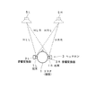
図1は、その原理を示し、同図(A)に示すように、リスナ1はヘッドホン3を装着して、その左右の音響変換器3Lおよび3Rによって音声を聴取し、同図(B)または(C)に示すように、リスナ1が右方向または左方向に向いても、音源5で示すリスナ頭外の任意の固定した位置に音像を定位させるものである。
【0004】
この場合、音源5からリスナ1の左耳1Lおよび右耳1Rに至る伝達関数をHLおよびHRとし、特にリスナ1が所定の方向、例えば音源5の方向を向いているときの、音源5からリスナ1の左耳1Lおよび右耳1Rに至る伝達関数をHLcおよびHRcとする。以下では、リスナ1の向きを、音源5の方向に対する回転角θで示す。
【0005】
図17は、この場合の従来の音声再生システムの一例を示し、ヘッドホン3には角速度センサ9が設けられ、この角速度センサ9の出力信号が積分されることによって、上記の回転角θが検出される。
【0006】
この例では、図1の音源5の信号に相当する入力デジタル音声信号Diが、デジタルフィルタ31および32に供給される。デジタルフィルタ31および32は、デジタル音声信号Diから上記の伝達関数HLcおよびHRcに相当するインパルス応答を畳み込むもので、例えば、FIR(Finite Impulse Response)フィルタによって構成される。
【0007】
デジタルフィルタ31および32の出力の音声信号L1およびR1は、時間差設定回路38に供給され、時間差設定回路38の出力の音声信号L2およびR2は、レベル差設定回路39に供給される。
【0008】
図1(B)のようにリスナ1が右方向に向いたとき、θ=0度〜+90度の範囲内では、回転角θが大きいほど、リスナ1の左耳1Lは音源5に近づき、右耳1Rは音源5から遠ざかるため、音源5の位置に音像を固定して定位させるには、伝達関数HLについては、回転角θが大きいほど、時間遅れが小さくなり、かつ信号レベルが大きくなるように、伝達関数HLcに対して変化させ、伝達関数HRについては、回転角θが大きいほど、時間遅れが大きくなり、かつ信号レベルが小さくなるように、伝達関数HRcに対して変化させる必要がある。
【0009】
逆に、図1(C)のようにリスナ1が左方向に向いたとき、θ=0度〜−90度の範囲内では、回転角θが大きいほど、リスナ1の左耳1Lは音源5から遠ざかり、右耳1Rは音源5に近づくため、音源5の位置に音像を固定して定位させるには、伝達関数HLについては、回転角θが大きいほど、時間遅れが大きくなり、かつ信号レベルが小さくなるように、伝達関数HLcに対して変化させ、伝達関数HRについては、回転角θが大きいほど、時間遅れが小さくなり、かつ信号レベルが大きくなるように、伝達関数HRcに対して変化させる必要がある。
【0010】
図17の音声再生システムでは、このリスナの左耳で聴取される音声信号と右耳で聴取される音声信号との間の時間差が時間差設定回路38で設定され、レベル差がレベル差設定回路39で設定される。
【0011】
具体的に、時間差設定回路38は、時間遅れ設定回路51および52によって構成され、時間遅れ設定回路51および52では、デジタルフィルタ31および32の出力の音声信号L1およびR1が、それぞれのサンプリング周期τの遅延時間の、多段接続された遅延回路53および54によって順次遅延される。
【0012】
音声信号L1,R1のサンプリング周波数fsは、例えば、44.1kHzであり、したがって、音声信号L1,R1のサンプリング周期τは、例えば、約22.7μ秒であり、リスナ頭部の回転角では約3度に相当する。
【0013】
時間遅れ設定回路51および52では、セレクタ55および56によって、上記のように検出された回転角θに最も近い回転角(向き)に対応する遅延回路の出力信号が、時間差設定回路38の出力の音声信号L2およびR2として取り出される。
【0014】
例えば、回転角θが0度のときには、セレクタ55および56からは、それぞれ中間の段の遅延回路の出力信号LtおよびRtが取り出され、回転角θが+α(右方向にαで、αはτに相当する約3度)のときには、セレクタ55からは信号Ltよりτだけ進んだ信号Lsが、セレクタ56からは信号Rtよりτだけ遅れた信号Ruが、それぞれ取り出され、回転角θが−α(左方向にα)のときには、セレクタ55からは信号Ltよりτだけ遅れた信号Luが、セレクタ56からは信号Rtよりτだけ進んだ信号Rsが、それぞれ取り出される。
【0015】
さらに、レベル差設定回路39では、検出された回転角θに応じて、時間差設定回路38の出力の音声信号L2およびR2のレベルが設定され、音声信号L2,R2間のレベル差が設定される。
【0016】
そして、レベル差設定回路39の出力のデジタル音声信号L3およびR3が、D/A(Digital to Analog)コンバータ41Lおよび41Rでアナログ音声信号に変換され、その2系統のアナログ音声信号が、音声増幅回路42Lおよび42Rで増幅されて、ヘッドホン3の左右の音響変換器3Lおよび3Rに供給される。
【0017】
図18は、従来の音声再生システムの他の例を示す。この例では、それぞれ回転角θがθ0,θ1,θ2,‥‥θnのときの、図1の音源5からリスナ1の左耳1Lに至る伝達関数HL(θ0),HL(θ1),HL(θ2),‥‥HL(θn)および音源5からリスナ1の右耳1Rに至る伝達関数HR(θ0),HR(θ1),HR(θ2),‥‥HR(θn)に相当するインパルス応答を畳み込むデジタルフィルタ83−0,83−1,83−2,‥‥83−nおよびデジタルフィルタ84−0,84−1,84−2,‥‥84−nが設けられる。θ0,θ1,θ2,‥‥θnは、リスナの周囲方向に等角間隔で設定される。
【0018】
そして、入力デジタル音声信号Diが、デジタルフィルタ83−0,83−1,83−2,‥‥83−nおよびデジタルフィルタ84−0,84−1,84−2,‥‥84−nに供給され、セレクタ55によって、デジタルフィルタ83−0,83−1,83−2,‥‥83−nのうちの、検出された回転角θに最も近い回転角(向き)に対応するフィルタの出力信号が、ヘッドホン3の左側の音響変換器3Lに供給されるべき音声信号として取り出され、セレクタ56によって、デジタルフィルタ84−0,84−1,84−2,‥‥84−nのうちの、検出された回転角θに最も近い回転角(向き)に対応するフィルタの出力信号が、ヘッドホン3の右側の音響変換器3Rに供給されるべき音声信号として取り出される。
【0019】
セレクタ55および56の出力のデジタル音声信号は、D/Aコンバータ41Lおよび41Rでアナログ音声信号に変換され、その2系統のアナログ音声信号が、音声増幅回路42Lおよび42Rで増幅されて、ヘッドホン3の左右の音響変換器3Lおよび3Rに供給される。
【0020】
【発明が解決しようとする課題】
しかしながら、図17の従来の音声再生システムでは、図1の音源5からリスナ1の左耳1Lおよび右耳1Rに至る伝達関数HLおよびHRにおける時間遅れの分解能が、時間遅れ設定回路51および52の遅延回路53および54の遅延時間、すなわちデジタルフィルタ31および32の出力の音声信号L1およびR1のサンプリング周期τによって決定され、音声信号L1,R1のサンプリング周波数fsが44.1kHz、サンプリング周期τが約22.7μ秒であるとき、リスナ頭部の回転角で約3度に相当するものとなる。
【0021】
そのため、リスナの向きが、±1.5度、±4.5度、というような、デジタルフィルタ31および32の出力の音声信号L1およびR1のサンプリング周期τで決まる0度または±3度の整数倍という離散的な所定方向の間の方向であるときには、リスナの向きに正確に対応させて、図1の音源5で示す所定位置に音像を定位させることができない。
【0022】
また、リスナが向きを変えたとき、単位角度ごとに時間差設定回路38の出力の音声信号L2およびR2が瞬間的に切り替えられるため、音声信号L2およびR2の波形変化が急峻となり、伝達特性の変化が急激となって、シヨックノイズが発生する。
【0023】
図18の従来の音声再生システムでも、リスナの向きが、θ0とθ1の間、θ1とθ2の間、というような、離散的な所定方向の間の方向であるときには、リスナの向きに正確に対応させて、図1の音源5で示す所定位置に音像を定位させることができないとともに、リスナが向きを変えたとき、単位角度ごとにセレクタ55および56の出力の音声信号が瞬間的に切り替えられるため、出力の音声信号の波形変化が急峻となり、伝達特性の変化が急激となって、シヨックノイズが発生する。
【0024】
そこで、この発明は、リスナ頭外の任意の固定した位置に音像を定位させる場合に、リスナの向きに正確に対応させて、常に所定位置に音像を定位させることができるとともに、リスナが向きを変えたときのショックノイズが低減し、音質の良い音声信号が得られるようにしたものである。
【0025】
【課題を解決するための手段】
この発明の音声信号処理方法では、入力音声信号をそれぞれインパルス応答の畳み込み用にフィルタリングして第1の複数の音声信号と第2の複数の音声信号とを得、前記第1の複数の音声信号からリスナの向きに対応した信号を選択して第1の遅延音声信号対を出力し、前記第2の複数の音声信号から前記リスナの向きに対応した信号を選択して第2の遅延音声信号対を出力し、前記第1の遅延音声信号対及び前記第2の遅延音声信号対をそのときの前記リスナの向きに応じた比率でそれぞれ加算して出力音声信号を得る。
【0026】
また、この発明の音声信号処理方法では、入力音声信号をそれぞれインパルス応答の畳み込み用にフィルタリングして第1の複数の音声信号と第2の複数の音声信号とを得て、前記第1の複数の音声信号から定位させる音像位置に対応した信号を選択して第1の遅延音声信号対を出力し、前記第2の複数の音声信号から定位させる音像位置に対応した信号を選択して第2の遅延音声信号対を出力し、前記第1の遅延音声信号対及び前記第2の遅延音声信号対を、そのときの定位させる音像位置に応じた比率でそれぞれ加算して出力音声信号を得る。
【0027】
また、この発明の音声信号処理方法では、
入力音声信号を、インパルス応答の畳み込み用にフィルタリングし、フィルタリング後の音声信号のサンプリング周波数を逓倍した後、逓倍後の音声信号を遅延させて、出力音声信号を得る。
【0028】
【発明の実施の形態】
〔第1の実施形態…図1〜図12〕
図2は、図1のように1チャンネルの音声信号をヘッドホンによって聴取する場合の、この発明の音声再生システムの一実施形態を示す。
【0029】
ヘッドホン3には、角速度センサ9を設ける。角速度センサ9の出力信号は、帯域制限フィルタ45で帯域制限し、さらにA/D(Analog to Digital)コンバータ46でデジタルデータに変換して、マイクロプロセッサ47に取り込み、マイクロプロセッサ47で積分して、ヘッドホン3を装着したリスナ頭部の回転角(向き)θを検出する。
【0030】
端子11に供給される、図1の音源5の信号に相当する入力アナログ音声信号Aiを、A/Dコンバータ21でデジタル音声信号Diに変換し、そのデジタル音声信号Diを、信号処理部30に供給する。
【0031】
信号処理部30は、専用のDSP(Digital Signal Processor)などによってソフトウェア(処理プログラム)を含むものとして、またはハードウェア回路として、機能的に、デジタルフィルタ31,32、時間差設定回路38およびレベル差設定回路39によって構成し、A/Dコンバータ21からのデジタル音声信号Diを、デジタルフィルタ31および32に供給する。
【0032】
デジタルフィルタ31および32は、リスナが所定の方向、例えば図1(A)のように音源5の方向を向いているときの、音源5からリスナ1の左耳1Lおよび右耳1Rに至る伝達関数HLcおよびHRcに相当する、図3に示すようなインパルス応答を畳み込むもので、例えば、図4に示すようなFIRフィルタによって構成する。
【0033】
すなわち、デジタルフィルタ31および32では、それぞれ、入力端子91に供給された音声信号を、そのサンプリング周期τの遅延時間の、多段接続された遅延回路92によって順次遅延し、各乗算回路93において、入力端子91に供給された音声信号および各遅延回路92の出力信号にインパルス応答の係数を乗じ、各加算回路94において、各乗算回路93の出力信号を順次加算し、出力端子95にフィルタリング後の音声信号を得る。
【0034】
このデジタルフィルタ31および32の出力の音声信号L1およびR1は、時間差設定回路38に供給し、時間差設定回路38の出力の音声信号L2およびR2は、レベル差設定回路39に供給する。
【0035】
図1の音源5の位置に音像を固定して定位させるには、音源5からリスナ1の左耳1Lおよび右耳1Rに至る伝達関数HLおよびHRにおける時間遅れを、上記のように検出された回転角θに対して、それぞれ図5の実線TdLおよび破線TdRで示すように変化させる必要があり、伝達関数HLおよびHRにおける信号レベルを、検出された回転角θに対して、それぞれ図6の実線LeLおよび破線LeRで示すように変化させる必要がある。θ=±180度というのは、リスナ1が音源5に対して真後ろに向いた場合である。
【0036】
このリスナの左耳で聴取される音声信号と右耳で聴取される音声信号との間の時間差を時間差設定回路38で設定し、レベル差をレベル差設定回路39で設定する。
【0037】
(時間差設定回路の一例…図7〜図11)
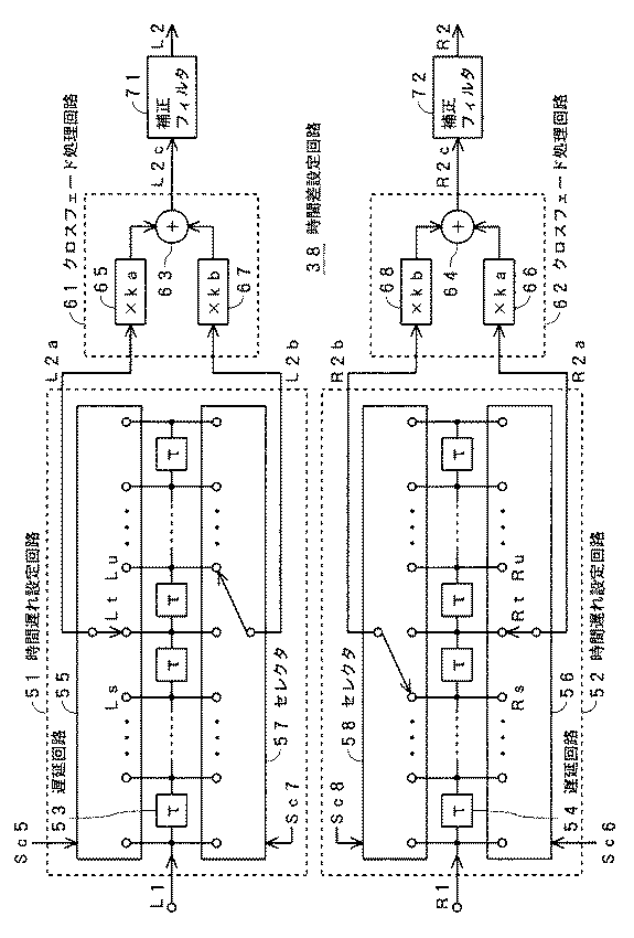
図7は、図2の実施形態の音声再生システムの時間差設定回路38の一例を示す。この例の時間差設定回路38は、時間遅れ設定回路51,52、クロスフェード処理回路61,62および補正フィルタ71,72によって構成する。
【0038】
時間遅れ設定回路51および52では、図2のデジタルフィルタ31および32の出力の音声信号L1およびR1を、それぞれのサンプリング周期τの遅延時間の、多段接続した遅延回路53および54によって順次遅延させる。
【0039】
音声信号L1,R1のサンプリング周波数fsは、例えば、44.1kHzであり、したがって、音声信号L1,R1のサンプリング周期τは、例えば、約22.7μ秒であり、リスナ頭部の回転角では約3度に相当する。
【0040】
時間遅れ設定回路51では、図2に示すようにマイクロプロセッサ47から信号処理部30に送出される、回転角θの検出結果に基づく音像定位制御信号Scの一部である選択信号Sc5およびSc7によって、セレクタ55および57で、検出された回転角θに最も近い回転角(向き)およびそれに次いで近い回転角(向き)に対応した隣接する2段の遅延回路の出力信号を、時間遅れ設定回路51の出力の音声信号L2aおよびL2bとして取り出し、時間遅れ設定回路52では、上記の音像定位制御信号Scの一部である選択信号Sc6およびSc8によって、セレクタ56および58で、検出された回転角θに最も近い回転角(向き)およびそれに次いで近い回転角(向き)に対応した隣接する2段の遅延回路の出力信号を、時間遅れ設定回路52の出力の音声信号R2aおよびR2bとして取り出す。
【0041】
例えば、回転角θが0度〜+α(右方向にαで、αはτに相当する約3度)のときには、時間遅れ設定回路51のセレクタ55からは、中間の段の遅延回路の出力信号Ltを音声信号L2aとして取り出し、セレクタ57からは、信号Ltよりτだけ進んだ信号Lsを音声信号L2bとして取り出すとともに、時間遅れ設定回路52のセレクタ56からは、中間の段の遅延回路の出力信号Rtを音声信号R2aとして取り出し、セレクタ58からは、信号Rtよりτだけ遅れた信号Ruを音声信号R2bとして取り出す。
【0042】
また、回転角θが0度〜−α(左方向にα)のときには、時間遅れ設定回路51のセレクタ55からは、中間の段の遅延回路の出力信号Ltを音声信号L2aとして取り出し、セレクタ57からは、信号Ltよりτだけ遅れた信号Luを音声信号L2bとして取り出すとともに、時間遅れ設定回路52のセレクタ56からは、中間の段の遅延回路の出力信号Rtを音声信号R2aとして取り出し、セレクタ58からは、信号Rtよりτだけ進んだ信号Rsを音声信号R2bとして取り出す。
【0043】
そして、時間遅れ設定回路51の出力の音声信号L2aおよびL2bを、クロスフェード処理回路61に供給し、時間遅れ設定回路52の出力の音声信号R2aおよびR2bを、クロスフェード処理回路62に供給する。
【0044】
クロスフェード処理回路61では、乗算回路65で音声信号L2aに係数kaを乗じ、乗算回路67で音声信号L2bに係数kbを乗じ、加算回路63で乗算回路65および67の乗算結果を加算する。同様に、クロスフェード処理回路62では、乗算回路66で音声信号R2aに係数kaを乗じ、乗算回路68で音声信号R2bに係数kbを乗じ、加算回路64で乗算回路66および68の乗算結果を加算する。
【0045】
すなわち、クロスフェード処理回路61および62の出力として、
L2c=ka×L2a+kb×L2b …(1)
R2c=ka×R2a+kb×R2b …(2)
で表される音声信号L2cおよびR2cを得る。
【0046】
係数ka,kbは、検出された回転角θに応じて、例えば、図8に示すように、10段階に設定し、リスナが向きを変えたときには、例えば、図9に示すように、τの時間ごとに変更する。
【0047】
すなわち、リスナの向きが0度のときには、ka=1,kb=0とし、向きが±α/10のときには、ka=0.9,kb=0.1とし、向きが±2α/10のときには、ka=0.8,kb=0.2とし、向きが±3α/10のときには、ka=0.7,kb=0.3とし、向きが±4α/10のときには、ka=0.6,kb=0.4とし、向きが±5α/10のときには、ka=0.5,kb=0.5とし、向きが±6α/10のときには、ka=0.4,kb=0.6とし、向きが±7α/10のときには、ka=0.3,kb=0.7とし、向きが±8α/10のときには、ka=0.2,kb=0.8とし、向きが±9α/10のときには、ka=0.1,kb=0.9とする。リスナの向きが、±αと±2αの間、±2αと±3αの間、などのときにも、同様である。
【0048】
したがって、リスナが0度の方向を向いているときには、
L2c=L2a=Lt …(3)
R2c=R2a=Rt …(4)
となる。
【0049】
また、このように0度の方向を向いている状態から、リスナが向きを変えて、−α/2の方向に向いたときには、
【0050】
さらに、このように−α/2の方向を向いている状態から、リスナが向きを変えて、−αの方向に向いたときには、ka=1,kb=0となるとともに、セレクタ55からは信号Luが取り出され、セレクタ57からは信号Luよりτだけ遅れた信号が取り出され、セレクタ56からは信号Rsが取り出され、セレクタ58からは信号Rsよりτだけ進んだ信号が取り出されるように、セレクタ55,57,56,58が切り替えられて、
L2c=L2a=Lu …(7)
R2c=R2a=Rs …(8)
となる。
【0051】
したがって、この例では、図1の音源5からリスナ1の左耳1Lおよび右耳1Rに至る伝達関数HLおよびHRにおける時間遅れの分解能が、時間遅れ設定回路51および52の遅延回路53および54の遅延時間、すなわちデジタルフィルタ31および32の出力の音声信号L1およびR1のサンプリング周期τの1/10に相当するものとなり、音声信号L1,R1のサンプリング周波数fsが44.1kHz、サンプリング周期τが約22.7μ秒であるとき、リスナ頭部の回転角で約0.3度に相当するものとなる。
【0052】
そのため、リスナの向きが、±1.5度、±4.5度、というような、デジタルフィルタ31および32の出力の音声信号L1およびR1のサンプリング周期τで決まる0度または±3度の整数倍という離散的な所定方向の間の方向であるときにも、リスナの向きに正確に対応させて、図1の音源5で示す所定位置に音像を定位させることができる。
【0053】
しかも、上記のような補間によって、リスナが向きを変えたとき、音声信号L2cおよびR2cの波形変化が緩やかとなり、伝達特性の変化が緩やかとなるので、シヨックノイズが低減する。
【0054】
ただし、この場合、時間遅れ設定回路51とクロスフェード処理回路61、および時間遅れ設定回路52とクロスフェード処理回路62は、それぞれ、一種のFIRフィルタを構成するため、係数ka,kbの値に応じて周波数特性が変化し、図10に示すように、ka=1,kb=0のときには、平坦な周波数特性Faとなるが、ka=0.75,kb=0.25のときには、高域が低下する周波数特性Fbとなり、ka=0.5,kb=0.5のときには、さらに高域が低下する周波数特性Fcとなる。
【0055】
そのため、図7の例では、クロスフェード処理回路61および62の出力の音声信号L2cおよびR2cを、高域補償用の補正フィルタ71および72に供給する。
【0056】
補正フィルタ71,72は、例えば、図11に示すように、入力の音声信号L2c,R2cを遅延回路74でτだけ遅延させ、後述の出力の音声信号L2,R2を遅延回路75でτだけ遅延させ、乗算回路76,77および78で、それぞれ入力の音声信号L2c,R2c、遅延回路74の出力信号および遅延回路75の出力信号に係数を乗じ、加算回路79で乗算回路76,77および78の乗算結果を加算し、その加算結果を出力の音声信号L2,R2として取り出す構成とする。乗算回路76〜78の係数は、上記の音像定位制御信号Scの一部である係数設定信号Sckによって、上記の係数ka,kbの値に応じて設定する。
【0057】
これによって、補正フィルタ71および72の出力の音声信号L2およびR2として、高域が補償された音声信号が得られる。
【0058】
図7の例の時間差設定回路38では、この補正フィルタ71および72の出力の音声信号L2およびR2を、時間差設定回路38の出力の音声信号として取り出して、図2に示すように、信号処理部30のレベル差設定回路39に供給する。
【0059】
レベル差設定回路39では、音像定位制御信号Scによって、検出された回転角θに応じて、図6に示した特性に従って、時間差設定回路38の出力の音声信号L2およびR2のレベルを設定し、音声信号L2,R2間のレベル差を設定する。
【0060】
そして、このレベル差設定回路39の出力のデジタル音声信号L3およびR3を、D/Aコンバータ41Lおよび41Rでアナログ音声信号に変換し、その2系統のアナログ音声信号を、音声増幅回路42Lおよび42Rで増幅して、ヘッドホン3の左右の音響変換器3Lおよび3Rに供給する。
【0061】
(時間差設定回路の他の例…図12)
図12は、図2の実施形態の音声再生システムの時間差設定回路38の他の例を示す。この例の時間差設定回路38は、オーバーサンプリングフィルタ81,82および時間遅れ設定回路51,52によって構成する。
【0062】
オーバーサンプリングフィルタ81および82では、図2のデジタルフィルタ31および32の出力信号を、サンプリング周波数がfsの音声信号L1およびR1から、サンプリング周波数がnfs(fsのn倍)の音声信号LnおよびRnに変換する。例えば、n=4として、デジタルフィルタ31および32の出力の音声信号のサンプリング周波数を、上記の44.1kHzから176.4kHzに変換する。
【0063】
時間遅れ設定回路51および52では、このオーバーサンプリングフィルタ81および82の出力の音声信号LnおよびRnを、それぞれのサンプリング周期τ/nの遅延時間の、多段接続した遅延回路53および54によって順次遅延させる。
【0064】
音声信号L1,R1のサンプリング周波数fsが44.1kHzで、n=4とする場合、音声信号Ln,Rnのサンプリング周期τ/nは、約5.7μ秒であり、リスナ頭部の回転角では約0.75度に相当する。
【0065】
さらに、時間遅れ設定回路51および52では、上記の音像定位制御信号Scの一部である選択信号Sc5およびSc6によって、セレクタ55および56で、検出された回転角θに最も近い回転角(向き)に対応する遅延回路の出力信号を、時間差設定回路38の出力の音声信号L2およびR2として取り出す。
【0066】
例えば、回転角θが0度のときには、セレクタ55および56からは、それぞれ中間の段の遅延回路の出力信号LpおよびRpを取り出し、回転角θが+α/n(右方向にα/nで、α/nはτ/nに相当する約0.75度)のときには、セレクタ55からは信号Lpよりτ/nだけ進んだ信号Loを、セレクタ56からは信号Rpよりτ/nだけ遅れた信号Rqを、それぞれ取り出し、回転角θが−α/n(左方向にα/n)のときには、セレクタ55からは信号Lpよりτ/nだけ遅れた信号Lqを、セレクタ56からは信号Rpよりτ/nだけ進んだ信号Roを、それぞれ取り出す。
【0067】
したがって、この例では、図1の音源5からリスナ1の左耳1Lおよび右耳1Rに至る伝達関数HLおよびHRにおける時間遅れの分解能が、デジタルフィルタ31および32の出力の音声信号L1およびR1のサンプリング周期τの1/nである、時間遅れ設定回路51および52の遅延回路53および54の遅延時間τ/nに相当するものとなり、音声信号L1,R1のサンプリング周波数fsが44.1kHz、サンプリング周期τが約22.7μ秒、n=4であるとき、リスナ頭部の回転角で約0.75度に相当するものとなる。
【0068】
そのため、リスナの向きが、±1.5度、±4.5度というような、デジタルフィルタ31および32の出力の音声信号L1およびR1のサンプリング周期τで決まる0度または±3度の整数倍という離散的な所定方向の間の方向であるときにも、リスナの向きに正確に対応させて、図1の音源5で示す所定位置に音像を定位させることができる。
【0069】
しかも、リスナが向きを変えたとき、0.75度という小さな角度ごとに音声信号L2およびR2が切り替えられるので、音声信号L2およびR2の波形変化が緩やかとなり、伝達特性の変化が緩やかとなって、シヨックノイズが低減する。
【0070】
〔第2の実施形態…図13および図14〕
この発明は、ステレオ音声信号をヘッドホンによって聴取する場合にも、適用することができる。
【0071】
図13は、この場合の原理を示し、リスナ1はヘッドホン3を装着して、その左右の音響変換器3Lおよび3Rによって音声を聴取し、リスナ1が右方向または左方向に向いても、それぞれ音源5Lおよび5Rで示すリスナ頭外の任意の固定した左右位置に、左右の音声信号の音像を定位させるものである。
【0072】
同図のようにリスナ1が所定の方向を向いているときの、音源5Lからリスナ1の左耳1Lおよび右耳1Rに至る伝達関数をHLLおよびHLRとし、音源5Rからリスナ1の左耳1Lおよび右耳1Rに至る伝達関数をHRLおよびHRRとする。
【0073】
図14は、この場合の、この発明の音声再生システムの一実施形態を示す。入力端子13および15に供給される、図13の音源5Lおよび5Rの信号に相当する左右の入力アナログ音声信号AlおよびArを、A/Dコンバータ23および25でデジタル音声信号DlおよびDrに変換し、そのデジタル音声信号DlおよびDrを、信号処理部30に供給する。
【0074】
信号処理部30は、機能的に、それぞれ上記の伝達関数HLL,HLR,HRL,HRRに相当するインパルス応答を畳み込むデジタルフィルタ33,34,35,36を有するものとして構成する。
【0075】
そして、A/Dコンバータ23からのデジタル音声信号Dlを、デジタルフィルタ33および34に供給し、A/Dコンバータ25からのデジタル音声信号Drを、デジタルフィルタ35および36に供給し、加算回路37Lで、デジタルフィルタ33および35の出力の音声信号を加算し、加算回路37Rで、デジタルフィルタ34および36の出力の音声信号を加算し、加算回路37Lおよび37Rの出力の音声信号L1およびR1を、時間差設定回路38に供給する。
【0076】
時間差設定回路38以降の構成は、図2の実施形態と同じで、時間差設定回路38は、図7または図12の例のように構成する。
【0077】
したがって、この実施形態でも、リスナの向きに正確に対応させて、常に所定位置に音像を定位させることができるとともに、リスナが向きを変えたときのショックノイズが低減し、音質の良い音声信号が得られる。
【0078】
〔第3の実施形態…図15〕
図15は、この発明の音声再生システムの他の実施形態を示し、図1のように1チャンネルの音声信号をヘッドホンによって聴取する場合の別の実施形態である。
【0079】
この実施形態では、それぞれ回転角θがθ0,θ1,θ2,‥‥θnのときの、図1の音源5からリスナ1の左耳1Lに至る伝達関数HL(θ0),HL(θ1),HL(θ2),‥‥HL(θn)および音源5からリスナ1の右耳1Rに至る伝達関数HR(θ0),HR(θ1),HR(θ2),‥‥HR(θn)に相当するインパルス応答を畳み込むデジタルフィルタ83−0,83−1,83−2,‥‥83−nおよびデジタルフィルタ84−0,84−1,84−2,‥‥84−nを設け、A/Dコンバータ21からの入力デジタル音声信号Diを、デジタルフィルタ83−0,83−1,83−2,‥‥83−nおよびデジタルフィルタ84−0,84−1,84−2,‥‥84−nに供給する。θ0,θ1,θ2,‥‥θnは、リスナの周囲方向に等角間隔で設定する。
【0080】
図15では省略したが、図2および図14の実施形態と同様に、ヘッドホン3に設けた角速度センサ9の出力信号から、ヘッドホン3を装着したリスナ頭部の回転角(向き)θを検出する。
【0081】
そして、セレクタ55および57によって、デジタルフィルタ83−0,83−1,83−2,‥‥83−nのうちの、検出された回転角θに最も近い回転角(向き)およびそれに次いで近い回転角(向き)に対応した隣接する2つのフィルタの出力信号を、音声信号L2aおよびL2bとして取り出し、セレクタ56および58によって、デジタルフィルタ84−0,84−1,84−2,‥‥84−nのうちの、検出された回転角θに最も近い回転角(向き)およびそれに次いで近い回転角(向き)に対応した隣接する2つのフィルタの出力信号を、音声信号R2aおよびR2bとして取り出す。
【0082】
例えば、回転角θがθ0〜θ1のときには、セレクタ55からは、デジタルフィルタ83−0の出力信号を音声信号L2aとして取り出し、セレクタ57からは、デジタルフィルタ83−1の出力信号を音声信号L2bとして取り出すとともに、セレクタ56からは、デジタルフィルタ84−0の出力信号を音声信号R2aとして取り出し、セレクタ58からは、デジタルフィルタ84−1の出力信号を音声信号R2bとして取り出す。
【0083】
そして、セレクタ55および57の出力の音声信号L2aおよびL2bを、クロスフェード処理回路61に供給し、セレクタ56および58の出力の音声信号R2aおよびR2bを、クロスフェード処理回路62に供給する。
【0084】
クロスフェード処理回路61および62では、図2の実施形態の音声再生システムの図7の例の時間差設定回路38のそれと同様に、上記の式(1)および(2)に示した補間演算を行う。
【0085】
したがって、この実施形態でも、リスナの向きが、θ0とθ1の間、θ1とθ2の間、というような、離散的な所定方向の間の方向であるときにも、リスナの向きに正確に対応させて、図1の音源5で示す所定位置に音像を定位させることができるとともに、リスナが向きを変えたとき、音声信号L2cおよびR2cの波形変化が緩やかとなり、伝達特性の変化が緩やかとなって、シヨックノイズが低減する。
【0086】
この実施形態でも、図7の例のサンプリング周波数回路38と同様に、クロスフェード処理回路61および62の出力の音声信号L2cおよびR2cを、高域補償用の補正フィルタ71および72に供給して、クロスフェード処理回路61および62における高域の低下を補償する。
【0087】
この実施形態では、デジタルフィルタ83−0,83−1,83−2,‥‥83−nおよびデジタルフィルタ84−0,84−1,84−2,‥‥84−nによるフィルタリング中に、リスナの左耳で聴取される音声信号と右耳で聴取される音声信号との間の時間差およびレベル差を考慮するので、補正フィルタ71および72の出力の音声信号L2およびR2を、そのまま、D/Aコンバータ41Lおよび41Rでアナログ音声信号に変換し、その2系統のアナログ音声信号を、音声増幅回路42Lおよび42Rで増幅して、ヘッドホン3の左右の音響変換器3Lおよび3Rに供給する。
【0088】
〔第4の実施形態…図16〕
上述した各実施形態は、ヘッドホンによって音声を聴取し、かつリスナ頭外の任意の固定した位置に音像を定位させる場合であるが、この発明は、スピーカやヘッドホンによって音声を聴取し、かつリスナ周辺の任意の変更した位置に音像を定位させる場合にも適用することができる。
【0089】
図16は、この場合の、この発明の音声再生システムの一実施形態を示す。スピーカ6Lおよび6Rは、例えば、リスナ前方の正中面に対して対称な左右位置や、ゲーム機などの画像表示機器の左右位置に配置する。
【0090】
端子11に供給される入力アナログ音声信号Aiを、A/Dコンバータ21でデジタル音声信号Diに変換し、そのデジタル音声信号Diを、信号処理部30に供給する。
【0091】
信号処理部30は、機能的に、デジタルフィルタ101,102、時間差設定回路38、レベル差設定回路39およびクロストークキャンセル回路111,112によって構成し、A/Dコンバータ21からのデジタル音声信号Diを、デジタルフィルタ101および102に供給する。
【0092】
デジタルフィルタ101,102、時間差設定回路38およびレベル差設定回路39は、リスナが定位変更した音像位置からリスナの左耳および右耳に至る伝達関数を実現するものである。
【0093】
すなわち、この実施形態では、ジョイスティックなどの音像定位操作部120で、リスナが音像位置を定位変更する操作を行うことによって、音像定位操作部120から信号処理部30に、音像定位制御信号Scが送出される。
【0094】
その音像定位制御信号Scによって、スピーカ6Lに供給される音声信号とスピーカ6Rに供給される音声信号との間の時間差およびレベル差が設定されることによって、リスナが定位変更した音像位置からリスナの左耳および右耳に至る伝達関数が実現される。
【0095】
具体的に、時間差設定回路38は、図2の実施形態と同様に、図7または図12の例のように構成し、上記の音像定位制御信号Scによって、図7の例では、時間遅れ設定回路51のセレクタ55,57、および時間遅れ設定回路52のセレクタ56,58から、それぞれ、定位変更された音像位置に最も近い音像位置およびそれに次いで近い音像位置に対応した隣接する2段の遅延回路の出力信号を、時間遅れ設定回路51の出力の音声信号L2a,L2b、および時間遅れ設定回路52の出力の音声信号R2a,R2bとして取り出すとともに、定位変更された音像位置に応じて、クロスフェード処理回路61および62の係数ka,kbを設定し、図12の例では、時間遅れ設定回路51のセレクタ55、および時間遅れ設定回路52のセレクタ56から、それぞれ、定位変更された音像位置に最も近い音像位置に対応する遅延回路の出力信号を、時間遅れ設定回路51の出力の音声信号L2、および時間遅れ設定回路52の出力の音声信号R2として取り出す。
【0096】
これによって、リスナが定位変更した音像位置が、離散的な所定位置の間の位置であるときにも、その位置に音像を正確に定位させることができるとともに、リスナが音像位置を変更したとき、音声信号の波形変化が緩やかとなり、伝達特性の変化が緩やかとなって、シヨックノイズが低減する。
【0097】
クロストークキャンセル回路111および112は、スピーカ6L,6R間のクロストークをキャンセルするものである。
【0098】
信号処理部30の出力の2系統のデジタル音声信号SLおよびSRは、D/Aコンバータ41Lおよび41Rでアナログ音声信号に変換し、その2系統のアナログ音声信号を、音声増幅回路42Lおよび42Rで増幅して、スピーカ6Lおよび6Rに供給する。
【0099】
図16の実施形態は、図2の実施形態と同様に時間差設定回路38を設け、これを図7または図12の例のように構成する場合であるが、図15の実施形態のような信号処理構成とすることによって、リスナ周辺の任意の変更した位置に音像を定位させることもできる。
【0100】
【発明の効果】
上述したように、この発明によれば、リスナ頭外の任意の固定した位置に音像を定位させる場合に、リスナの向きに正確に対応させて、常に所定位置に音像を定位させることができるとともに、リスナが向きを変えたときのショックノイズが低減し、音質の良い音声信号が得られる。
また、この発明によれば、リスナ周辺の任意の変更した位置に音像を定位させる場合に、任意の位置に音像を正確に定位させることができるとともに、音像位置を変更したときのショックノイズが低減し、音質の良い音声信号が得られる。
【図面の簡単な説明】
【図1】リスナ頭外の固定位置に音像を定位させる場合の原理を示す図である。
【図2】この発明の音声再生システムの第1の実施形態を示す図である。
【図3】インパルス応答の一例を示す図である。
【図4】デジタルフィルタの一例を示す図である。
【図5】リスナの向きとリスナの両耳に至る時間遅れとの関係を示す図である。
【図6】リスナの向きとリスナの両耳に至る信号レベルとの関係を示す図である。
【図7】図2のシステム中の時間差設定回路の一例を示す図である。
【図8】図7の時間差設定回路の説明に供する図である。
【図9】図7の時間差設定回路の説明に供する図である。
【図10】図7の時間差設定回路の説明に供する図である。
【図11】図7の時間差設定回路中の補正フィルタの一例を示す図である。
【図12】図2のシステム中の時間差設定回路の他の例を示す図である。
【図13】リスナ頭外の固定位置に音像を定位させる場合の原理を示す図である。
【図14】この発明の音声再生システムの第2の実施形態を示す図である。
【図15】この発明の音声再生システムの第3の実施形態を示す図である。
【図16】この発明の音声再生システムの第4の実施形態を示す図である。
【図17】従来の音声再生システムの一例を示す図である。
【図18】従来の音声再生システムの他の例を示す図である。
【符号の説明】
主要部については図中に全て記述したので、ここでは省略する。[0001]
BACKGROUND OF THE INVENTION
In the present invention, when listening to sound with headphones or the like and localizing the sound image at an arbitrary fixed position outside the listener's head, listening to sound with speakers or headphones, etc., and at any changed position around the listener The present invention relates to an audio signal processing method and an audio reproduction system when a sound image is localized.
[0002]
[Prior art]
When listening to sound through headphones, the sound image can be localized at any fixed position outside the listener's head, and the sound can be heard as if the speaker is placed at that position, regardless of the direction the listener is facing. Such a sound reproduction system has been considered.
[0003]
FIG. 1 shows the principle, and as shown in FIG. 1A, the
[0004]
In this case, the transfer functions from the
[0005]
FIG. 17 shows an example of a conventional sound reproduction system in this case. The
[0006]
In this example, an input digital audio signal Di corresponding to the signal of the
[0007]
The audio signals L1 and R1 output from the
[0008]
When the
[0009]
On the other hand, when the
[0010]
In the sound reproduction system of FIG. 17, the time difference between the sound signal heard by the listener's left ear and the sound signal heard by the right ear is set by the time
[0011]
Specifically, the time
[0012]
The sampling frequency fs of the audio signals L1 and R1 is, for example, 44.1 kHz. Therefore, the sampling period τ of the audio signals L1, R1 is, for example, about 22.7 μsec, and the rotation angle of the listener head is about It corresponds to 3 degrees.
[0013]
In the time
[0014]
For example, when the rotation angle θ is 0 degree, the output signals Lt and Rt of the intermediate stage delay circuit are taken out from the
[0015]
Further, the level difference setting
[0016]
The digital audio signals L3 and R3 output from the level difference setting
[0017]
FIG. 18 shows another example of a conventional audio reproduction system. In this example, transfer functions HL (θ0), HL (θ1), HL (from the
[0018]
The input digital audio signal Di is supplied to the digital filters 83-0, 83-1, 83-2,... 83-n and the digital filters 84-0, 84-1, 84-2,. The output signal of the filter corresponding to the rotation angle (direction) closest to the detected rotation angle θ among the digital filters 83-0, 83-1, 83-2,. Is extracted as an audio signal to be supplied to the
[0019]
The digital audio signals output from the
[0020]
[Problems to be solved by the invention]
However, in the conventional audio reproduction system of FIG. 17, the resolution of the time delay in the transfer functions HL and HR from the
[0021]
Therefore, an integer of 0 degree or ± 3 degrees determined by the sampling period τ of the audio signals L1 and R1 of the outputs of the
[0022]
Further, when the listener changes its direction, the audio signals L2 and R2 output from the time
[0023]
Also in the conventional audio reproduction system of FIG. 18, when the listener is in a direction between discrete predetermined directions, such as between θ0 and θ1, or between θ1 and θ2, the listener is accurately set in the direction of the listener. Correspondingly, the sound image cannot be localized at a predetermined position shown by the
[0024]
Therefore, according to the present invention, when a sound image is localized at an arbitrary fixed position outside the listener's head, the sound image can always be localized at a predetermined position by accurately corresponding to the orientation of the listener, and the listener can be oriented. The shock noise at the time of change is reduced, and a sound signal with good sound quality can be obtained.
[0025]
[Means for Solving the Problems]
In the audio signal processing method of the present invention, the input audio signal is Respectively Filtered for convolution of impulse response Obtaining a first plurality of audio signals and a second plurality of audio signals, selecting a signal corresponding to the direction of the listener from the first plurality of audio signals, and outputting a first delayed audio signal pair; Selecting a signal corresponding to the direction of the listener from the second plurality of audio signals and outputting a second delayed audio signal pair; The first delayed audio signal pair and the second delayed audio signal pair are added at a ratio corresponding to the direction of the listener at that time to obtain an output audio signal.
[0026]
In the audio signal processing method of the present invention, the input audio signal is filtered for convolution of the impulse response to obtain the first plurality of audio signals and the second plurality of audio signals, and the first plurality of audio signals are obtained. From the audio signal Sound image position to be localized To output a first delayed audio signal pair, and from the second plurality of audio signals Sound image position to be localized And outputs a second delayed audio signal pair, and the first delayed audio signal pair and the second delayed audio signal pair are Sound image position to be localized The output audio signal is obtained by adding the signals at a ratio according to the above.
[0027]
In the audio signal processing method of the present invention,
The input audio signal is filtered for convolution of an impulse response, the sampling frequency of the filtered audio signal is multiplied, and the multiplied audio signal is delayed to obtain an output audio signal.
[0028]
DETAILED DESCRIPTION OF THE INVENTION
[First Embodiment: FIGS. 1 to 12]
FIG. 2 shows an embodiment of the audio reproduction system of the present invention when a 1-channel audio signal is listened to through headphones as shown in FIG.
[0029]
The
[0030]
An input analog audio signal Ai corresponding to the signal of the
[0031]
The signal processing unit 30 includes software (processing program) by a dedicated DSP (Digital Signal Processor) or the like, or as a hardware circuit, functionally, the
[0032]
The
[0033]
That is, in each of the
[0034]
The audio signals L1 and R1 output from the
[0035]
In order to fix and localize the sound image at the position of the
[0036]
The time difference between the audio signal heard by the listener's left ear and the audio signal heard by the right ear is set by the time
[0037]
(Example of time difference setting circuit: FIGS. 7 to 11)
FIG. 7 shows an example of the time
[0038]
In the time
[0039]
The sampling frequency fs of the audio signals L1 and R1 is, for example, 44.1 kHz. Therefore, the sampling period τ of the audio signals L1, R1 is, for example, about 22.7 μsec, and the rotation angle of the listener head is about It corresponds to 3 degrees.
[0040]
In the time
[0041]
For example, when the rotation angle θ is 0 degree to + α (α in the right direction and α is about 3 degrees corresponding to τ), the
[0042]
When the rotation angle θ is 0 ° to −α (α to the left), the
[0043]
Then, the audio signals L2a and L2b output from the time
[0044]
In the
[0045]
That is, as outputs of the
L2c = ka × L2a + kb × L2b (1)
R2c = ka × R2a + kb × R2b (2)
Audio signals L2c and R2c represented by
[0046]
The coefficients ka and kb are set in 10 stages according to the detected rotation angle θ, for example, as shown in FIG. 8, and when the listener changes its direction, for example, as shown in FIG. Change every hour.
[0047]
That is, when the listener orientation is 0 degrees, ka = 1, kb = 0, when the orientation is ± α / 10, ka = 0.9, kb = 0.1, and when the orientation is ± 2α / 10. , Ka = 0.8, kb = 0.2, when the direction is ± 3α / 10, ka = 0.7, kb = 0.3, and when the direction is ± 4α / 10, ka = 0.6 , Kb = 0.4, when the direction is ± 5α / 10, ka = 0.5, kb = 0.5, and when the direction is ± 6α / 10, ka = 0.4, kb = 0.6 When the orientation is ± 7α / 10, ka = 0.3 and kb = 0.7. When the orientation is ± 8α / 10, ka = 0.2 and kb = 0.8, and the orientation is ± 9α. When / 10, ka = 0.1 and kb = 0.9. The same applies when the listener orientation is between ± α and ± 2α, between ± 2α and ± 3α, and the like.
[0048]
Therefore, when the listener is facing 0 degrees,
L2c = L2a = Lt (3)
R2c = R2a = Rt (4)
It becomes.
[0049]
In addition, when the listener changes direction from the state of facing the direction of 0 degrees in this way to the direction of -α / 2,
[0050]
Further, when the listener changes its direction from the state of being directed in the direction of -α / 2 in this way and is directed in the direction of -α, ka = 1 and kb = 0, and the
L2c = L2a = Lu (7)
R2c = R2a = Rs (8)
It becomes.
[0051]
Therefore, in this example, the resolution of the time delay in the transfer functions HL and HR from the
[0052]
Therefore, an integer of 0 degree or ± 3 degrees determined by the sampling period τ of the audio signals L1 and R1 of the outputs of the
[0053]
In addition, when the listener changes its direction by the interpolation as described above, the waveform change of the audio signals L2c and R2c becomes gradual and the change of the transfer characteristic becomes gradual, so that the shock noise is reduced.
[0054]
However, in this case, the time
[0055]
Therefore, in the example of FIG. 7, the audio signals L2c and R2c output from the
[0056]
For example, as shown in FIG. 11, the correction filters 71 and 72 delay input audio signals L2c and R2c by τ by a
[0057]
As a result, as the audio signals L2 and R2 output from the correction filters 71 and 72, an audio signal whose high frequency is compensated is obtained.
[0058]
In the time
[0059]
The level
[0060]
The digital audio signals L3 and R3 output from the level
[0061]
(Another example of the time difference setting circuit ... FIG. 12)
FIG. 12 shows another example of the time
[0062]
In the oversampling filters 81 and 82, the output signals of the
[0063]
In the time
[0064]
When the sampling frequency fs of the audio signals L1 and R1 is 44.1 kHz and n = 4, the sampling period τ / n of the audio signals Ln and Rn is about 5.7 μsec, and the rotation angle of the listener head is It corresponds to about 0.75 degree.
[0065]
Further, in the time
[0066]
For example, when the rotation angle θ is 0 degree, the
[0067]
Therefore, in this example, the time delay resolution in the transfer functions HL and HR from the
[0068]
Therefore, an integer multiple of 0 degrees or ± 3 degrees determined by the sampling period τ of the audio signals L1 and R1 of the outputs of the
[0069]
Moreover, when the listener changes its direction, the audio signals L2 and R2 are switched every small angle of 0.75 degrees, so that the waveform change of the audio signals L2 and R2 becomes gradual, and the change of the transfer characteristic becomes gradual. , The shock noise is reduced.
[0070]
[Second Embodiment: FIGS. 13 and 14]
The present invention can also be applied when listening to stereo audio signals with headphones.
[0071]
FIG. 13 shows the principle in this case. The
[0072]
The transfer functions from the sound source 5L to the left ear 1L and the
[0073]
FIG. 14 shows an embodiment of the audio reproduction system of the present invention in this case. The left and right input analog audio signals Al and Ar corresponding to the signals of the sound sources 5L and 5R in FIG. 13 supplied to the
[0074]
The signal processing unit 30 is functionally configured to include
[0075]
The digital audio signal Dl from the A /
[0076]
The configuration after the time
[0077]
Therefore, in this embodiment, the sound image can always be localized at a predetermined position by accurately corresponding to the direction of the listener, shock noise when the listener changes its direction is reduced, and a sound signal with good sound quality is generated. can get.
[0078]
[Third Embodiment ... FIG. 15]
FIG. 15 shows another embodiment of the sound reproduction system of the present invention, which is another embodiment in the case of listening to the sound signal of one channel using headphones as shown in FIG.
[0079]
In this embodiment, transfer functions HL (θ0), HL (θ1), HL from the
[0080]
Although omitted in FIG. 15, the rotation angle (direction) θ of the listener's head wearing the
[0081]
Then, by the
[0082]
For example, when the rotation angle θ is θ0 to θ1, the output signal of the digital filter 83-0 is extracted from the
[0083]
The audio signals L2a and L2b output from the
[0084]
In the
[0085]
Therefore, even in this embodiment, even when the orientation of the listener is a direction between discrete predetermined directions, such as between θ0 and θ1, or between θ1 and θ2, it accurately corresponds to the orientation of the listener. Thus, the sound image can be localized at a predetermined position shown by the
[0086]
Also in this embodiment, similarly to the
[0087]
In this embodiment, during filtering by the digital filters 83-0, 83-1, 83-2,... 83-n and the digital filters 84-0, 84-1, 84-2,. Since the time difference and the level difference between the audio signal heard by the left ear and the audio signal heard by the right ear are taken into account, the audio signals L2 and R2 output from the correction filters 71 and 72 are directly used as D /
[0088]
[Fourth Embodiment ... FIG. 16]
Each of the above-described embodiments is a case where the sound is listened to by headphones and the sound image is localized at an arbitrary fixed position outside the listener's head. The present invention can also be applied to a case where a sound image is localized at an arbitrarily changed position.
[0089]
FIG. 16 shows an embodiment of the audio reproduction system of the present invention in this case. The
[0090]
The input analog audio signal Ai supplied to the terminal 11 is converted into a digital audio signal Di by the A /
[0091]
The signal processing unit 30 is functionally configured by the
[0092]
The
[0093]
That is, in this embodiment, the sound image localization control signal Sc is sent from the sound image localization operation unit 120 to the signal processing unit 30 by the listener performing an operation of changing the localization of the sound image position in the sound image localization operation unit 120 such as a joystick. Is done.
[0094]
The sound image localization control signal Sc sets a time difference and a level difference between the audio signal supplied to the speaker 6L and the audio signal supplied to the
[0095]
Specifically, the time
[0096]
As a result, when the position of the sound image changed by the listener is a position between discrete predetermined positions, the sound image can be accurately positioned at that position, and when the listener changes the sound image position, The waveform change of the audio signal becomes gradual, the change of the transfer characteristic becomes gradual, and the shock noise is reduced.
[0097]
The crosstalk cancellation circuits 111 and 112 cancel the crosstalk between the
[0098]
The two digital audio signals SL and SR output from the signal processing unit 30 are converted into analog audio signals by the D /
[0099]
The embodiment of FIG. 16 is a case where the time
[0100]
【Effect of the invention】
As described above, according to the present invention, when a sound image is localized at an arbitrary fixed position outside the listener's head, the sound image can always be localized at a predetermined position by accurately corresponding to the direction of the listener. Shock noise when the listener changes direction is reduced, and a sound signal with good sound quality can be obtained.
Further, according to the present invention, when a sound image is localized at an arbitrarily changed position around the listener, the sound image can be accurately localized at an arbitrary position, and shock noise when the sound image position is changed is reduced. As a result, a sound signal with good sound quality can be obtained.
[Brief description of the drawings]
FIG. 1 is a diagram showing the principle when a sound image is localized at a fixed position outside a listener's head.
FIG. 2 is a diagram showing a first embodiment of an audio reproduction system according to the present invention.
FIG. 3 is a diagram illustrating an example of an impulse response.
FIG. 4 is a diagram illustrating an example of a digital filter.
FIG. 5 is a diagram showing the relationship between the direction of the listener and the time delay to reach both ears of the listener.
FIG. 6 is a diagram showing the relationship between the direction of the listener and the signal level reaching both ears of the listener.
7 is a diagram illustrating an example of a time difference setting circuit in the system of FIG. 2;
FIG. 8 is a diagram for explaining the time difference setting circuit of FIG. 7;
FIG. 9 is a diagram for explaining the time difference setting circuit of FIG. 7;
10 is a diagram for explaining the time difference setting circuit in FIG. 7; FIG.
11 is a diagram illustrating an example of a correction filter in the time difference setting circuit of FIG. 7;
12 is a diagram showing another example of the time difference setting circuit in the system of FIG. 2. FIG.
FIG. 13 is a diagram showing the principle when a sound image is localized at a fixed position outside the listener's head.
FIG. 14 is a diagram showing a second embodiment of the sound reproduction system of the present invention.
FIG. 15 is a diagram showing a third embodiment of the audio reproduction system of the present invention.
FIG. 16 is a diagram showing a fourth embodiment of the audio reproduction system of the present invention.
FIG. 17 is a diagram illustrating an example of a conventional audio reproduction system.
FIG. 18 is a diagram showing another example of a conventional audio reproduction system.
[Explanation of symbols]
Since all the main parts are described in the figure, they are omitted here.
Claims (8)
前記第1の複数の音声信号からリスナの向きに対応した信号を選択し、第1の遅延音声信号対を出力し、前記第2の複数の音声信号から前記リスナの向きに対応した信号を選択し、第2の遅延音声信号対を出力する選択ステップと、
前記第1の遅延音声信号対及び前記第2の遅延音声信号対を、そのときの前記リスナの向きに応じた比率でそれぞれ加算し、出力音声信号を得る演算ステップと
を含む音声信号処理方法。Filtering the input audio signal for convolution of each impulse response to obtain a first plurality of audio signals and a second plurality of audio signals;
A signal corresponding to the listener direction is selected from the first plurality of audio signals, a first delayed audio signal pair is output, and a signal corresponding to the listener direction is selected from the second plurality of audio signals. Selecting a second delayed audio signal pair;
An audio signal processing method comprising: a step of adding the first delayed audio signal pair and the second delayed audio signal pair at a ratio according to the direction of the listener at that time to obtain an output audio signal.
前記第1の複数の音声信号から定位させる音像位置に対応した信号を選択し、第1の遅延音声信号対を出力し、前記第2の複数の音声信号から定位させる音像位置に対応した信号を選択し、第2の遅延音声信号対を出力する選択ステップと、
前記第1の遅延音声信号対及び前記第2の遅延音声信号対を、そのときの定位させる音像位置に応じた比率でそれぞれ加算し、出力音声信号を得る演算ステップと
を含む音声信号処理方法。Filtering the input audio signal for convolution of each impulse response to obtain a first plurality of audio signals and a second plurality of audio signals;
A signal corresponding to a sound image position to be localized is selected from the first plurality of sound signals, a first delayed sound signal pair is output, and a signal corresponding to the sound image position to be localized is selected from the second plurality of sound signals. Selecting and outputting a second delayed audio signal pair;
An audio signal processing method comprising: a step of adding the first delayed audio signal pair and the second delayed audio signal pair at a ratio corresponding to a sound image position to be localized at that time to obtain an output audio signal.
前記第1の複数の音声信号からリスナの向きに対応した信号を選択し、第1の遅延音声信号対を出力し、前記第2の複数の音声信号から前記リスナの向きに対応した信号を選択し、第2の遅延音声信号対を出力する選択手段と、
前記第1の遅延音声信号対及び前記第2の遅延音声信号対を、そのときの前記リスナの向きに応じた比率でそれぞれ加算し、出力音声信号を得る演算手段と
を備える音声再生システム。Filtering means for filtering the input audio signal for convolution of each impulse response to obtain a first plurality of audio signals and a second plurality of audio signals;
A signal corresponding to the listener direction is selected from the first plurality of audio signals, a first delayed audio signal pair is output, and a signal corresponding to the listener direction is selected from the second plurality of audio signals. Selecting means for outputting the second delayed audio signal pair;
An audio reproduction system comprising: an arithmetic means for adding the first delayed audio signal pair and the second delayed audio signal pair at a ratio corresponding to the direction of the listener at that time to obtain an output audio signal.
前記第1の複数の音声信号から定位させる音像位置に対応した信号を選択し、第1の遅延音声信号対を出力し、前記第2の複数の音声信号から定位させる音像位置に対応した信号を選択し、第2の遅延音声信号対を出力する選択手段と、
前記第1の遅延音声信号対及び前記第2の遅延音声信号対を、そのときの定位させる音像位置に応じた比率でそれぞれ加算し、出力音声信号を得る演算手段と
を備える音声再生システム。Filtering means for filtering the input audio signal for convolution of each impulse response to obtain a first plurality of audio signals and a second plurality of audio signals;
A signal corresponding to a sound image position to be localized is selected from the first plurality of sound signals, a first delayed sound signal pair is output, and a signal corresponding to the sound image position to be localized is selected from the second plurality of sound signals. Selecting means for selecting and outputting a second delayed audio signal pair;
An audio reproduction system comprising: an arithmetic unit that adds the first delayed audio signal pair and the second delayed audio signal pair at a ratio corresponding to a sound image position to be localized at that time to obtain an output audio signal.
を備える音声再生システム。Filtering means for filtering the input voice signal for convolution of impulse response, oversampling means for multiplying the sampling frequency of the output voice signal of the filtering means, and time delay setting means for delaying the output voice signal of the oversampling means An audio playback system comprising:
Priority Applications (2)
| Application Number | Priority Date | Filing Date | Title |
|---|---|---|---|
| JP2001299283A JP4867121B2 (en) | 2001-09-28 | 2001-09-28 | Audio signal processing method and audio reproduction system |
| US10/252,969 US7454026B2 (en) | 2001-09-28 | 2002-09-23 | Audio image signal processing and reproduction method and apparatus with head angle detection |
Applications Claiming Priority (1)
| Application Number | Priority Date | Filing Date | Title |
|---|---|---|---|
| JP2001299283A JP4867121B2 (en) | 2001-09-28 | 2001-09-28 | Audio signal processing method and audio reproduction system |
Publications (2)
| Publication Number | Publication Date |
|---|---|
| JP2003111197A JP2003111197A (en) | 2003-04-11 |
| JP4867121B2 true JP4867121B2 (en) | 2012-02-01 |
Family
ID=19120059
Family Applications (1)
| Application Number | Title | Priority Date | Filing Date |
|---|---|---|---|
| JP2001299283A Expired - Fee Related JP4867121B2 (en) | 2001-09-28 | 2001-09-28 | Audio signal processing method and audio reproduction system |
Country Status (2)
| Country | Link |
|---|---|
| US (1) | US7454026B2 (en) |
| JP (1) | JP4867121B2 (en) |
Families Citing this family (23)
| Publication number | Priority date | Publication date | Assignee | Title |
|---|---|---|---|---|
| US7333622B2 (en) * | 2002-10-18 | 2008-02-19 | The Regents Of The University Of California | Dynamic binaural sound capture and reproduction |
| US20070009120A1 (en) * | 2002-10-18 | 2007-01-11 | Algazi V R | Dynamic binaural sound capture and reproduction in focused or frontal applications |
| US20080056517A1 (en) * | 2002-10-18 | 2008-03-06 | The Regents Of The University Of California | Dynamic binaural sound capture and reproduction in focued or frontal applications |
| FR2852779B1 (en) * | 2003-03-20 | 2008-08-01 | PROCESS FOR PROCESSING AN ELECTRICAL SIGNAL OF SOUND | |
| KR20050060789A (en) * | 2003-12-17 | 2005-06-22 | 삼성전자주식회사 | Apparatus and method for controlling virtual sound |
| JP3985234B2 (en) * | 2004-06-29 | 2007-10-03 | ソニー株式会社 | Sound image localization device |
| US7991176B2 (en) * | 2004-11-29 | 2011-08-02 | Nokia Corporation | Stereo widening network for two loudspeakers |
| US8243967B2 (en) * | 2005-11-14 | 2012-08-14 | Nokia Corporation | Hand-held electronic device |
| JP4867367B2 (en) * | 2006-01-30 | 2012-02-01 | ヤマハ株式会社 | Stereo sound reproduction device |
| EP1995993B1 (en) * | 2006-03-13 | 2016-05-11 | Panasonic Intellectual Property Corporation of America | Sound image localizer |
| US20080157991A1 (en) * | 2007-01-03 | 2008-07-03 | International Business Machines Corporation | Remote monitor device with sensor to control multimedia playback |
| US20090324002A1 (en) * | 2008-06-27 | 2009-12-31 | Nokia Corporation | Method and Apparatus with Display and Speaker |
| JP5499633B2 (en) | 2009-10-28 | 2014-05-21 | ソニー株式会社 | REPRODUCTION DEVICE, HEADPHONE, AND REPRODUCTION METHOD |
| CN102056054B (en) * | 2009-10-30 | 2013-09-18 | 扬智科技股份有限公司 | Sound playing device and compensation method thereof |
| EP2804402B1 (en) | 2012-01-11 | 2021-05-19 | Sony Corporation | Sound field control device, sound field control method and program |
| WO2013142653A1 (en) | 2012-03-23 | 2013-09-26 | Dolby Laboratories Licensing Corporation | Method and system for head-related transfer function generation by linear mixing of head-related transfer functions |
| EP2747314A1 (en) * | 2012-12-19 | 2014-06-25 | Nxp B.V. | A system for blending signals |
| GB2544458B (en) * | 2015-10-08 | 2019-10-02 | Facebook Inc | Binaural synthesis |
| CN112954582B (en) * | 2016-06-21 | 2024-08-02 | 杜比实验室特许公司 | Head tracking for pre-rendered binaural audio |
| WO2017223110A1 (en) * | 2016-06-21 | 2017-12-28 | Dolby Laboratories Licensing Corporation | Headtracking for pre-rendered binaural audio |
| US20180032212A1 (en) | 2016-08-01 | 2018-02-01 | Facebook, Inc. | Systems and methods to manage media content items |
| EP3967061A1 (en) | 2019-10-22 | 2022-03-16 | Google LLC | Spatial audio for wearable devices |
| CN111049997B (en) * | 2019-12-25 | 2021-06-11 | 携程计算机技术(上海)有限公司 | Telephone background music detection model method, system, equipment and medium |
Family Cites Families (24)
| Publication number | Priority date | Publication date | Assignee | Title |
|---|---|---|---|---|
| US3970787A (en) * | 1974-02-11 | 1976-07-20 | Massachusetts Institute Of Technology | Auditorium simulator and the like employing different pinna filters for headphone listening |
| JPS5280001A (en) * | 1975-12-26 | 1977-07-05 | Victor Co Of Japan Ltd | Binaural system |
| DE3168990D1 (en) * | 1980-03-19 | 1985-03-28 | Matsushita Electric Industrial Co Ltd | Sound reproducing system having sonic image localization networks |
| US5495534A (en) * | 1990-01-19 | 1996-02-27 | Sony Corporation | Audio signal reproducing apparatus |
| JP3255179B2 (en) * | 1992-02-14 | 2002-02-12 | ソニー株式会社 | Data detection device |
| US5517570A (en) * | 1993-12-14 | 1996-05-14 | Taylor Group Of Companies, Inc. | Sound reproducing array processor system |
| US5745584A (en) * | 1993-12-14 | 1998-04-28 | Taylor Group Of Companies, Inc. | Sound bubble structures for sound reproducing arrays |
| US5590207A (en) * | 1993-12-14 | 1996-12-31 | Taylor Group Of Companies, Inc. | Sound reproducing array processor system |
| JPH11503882A (en) * | 1994-05-11 | 1999-03-30 | オーリアル・セミコンダクター・インコーポレーテッド | 3D virtual audio representation using a reduced complexity imaging filter |
| US5757931A (en) * | 1994-06-15 | 1998-05-26 | Sony Corporation | Signal processing apparatus and acoustic reproducing apparatus |
| JP3385725B2 (en) * | 1994-06-21 | 2003-03-10 | ソニー株式会社 | Audio playback device with video |
| JPH08107600A (en) * | 1994-10-04 | 1996-04-23 | Yamaha Corp | Sound image localization device |
| JPH08182100A (en) * | 1994-10-28 | 1996-07-12 | Matsushita Electric Ind Co Ltd | Sound image localization method and sound image localization device |
| JPH08191225A (en) * | 1995-01-09 | 1996-07-23 | Matsushita Electric Ind Co Ltd | Sound field playback device |
| JPH099398A (en) * | 1995-06-20 | 1997-01-10 | Matsushita Electric Ind Co Ltd | Sound image localization device |
| JPH0946800A (en) * | 1995-07-28 | 1997-02-14 | Sanyo Electric Co Ltd | Sound image controller |
| JP3577798B2 (en) * | 1995-08-31 | 2004-10-13 | ソニー株式会社 | Headphone equipment |
| JP3255348B2 (en) * | 1996-11-27 | 2002-02-12 | 株式会社河合楽器製作所 | Delay amount control device and sound image control device |
| JPH10136497A (en) * | 1996-10-24 | 1998-05-22 | Roland Corp | Sound image localizing device |
| JPH1188994A (en) * | 1997-09-04 | 1999-03-30 | Matsushita Electric Ind Co Ltd | Sound image localization device and sound image control method |
| JPH11275696A (en) * | 1998-01-22 | 1999-10-08 | Sony Corp | Headphone, headphone adapter and headphone device |
| US6973184B1 (en) * | 2000-07-11 | 2005-12-06 | Cisco Technology, Inc. | System and method for stereo conferencing over low-bandwidth links |
| JP4737804B2 (en) * | 2000-07-25 | 2011-08-03 | ソニー株式会社 | Audio signal processing apparatus and signal processing apparatus |
| JP3435156B2 (en) * | 2001-07-19 | 2003-08-11 | 松下電器産業株式会社 | Sound image localization device |
-
2001
- 2001-09-28 JP JP2001299283A patent/JP4867121B2/en not_active Expired - Fee Related
-
2002
- 2002-09-23 US US10/252,969 patent/US7454026B2/en not_active Expired - Lifetime
Also Published As
| Publication number | Publication date |
|---|---|
| US7454026B2 (en) | 2008-11-18 |
| JP2003111197A (en) | 2003-04-11 |
| US20030076973A1 (en) | 2003-04-24 |
Similar Documents
| Publication | Publication Date | Title |
|---|---|---|
| JP4867121B2 (en) | Audio signal processing method and audio reproduction system | |
| US8520857B2 (en) | Head-related transfer function measurement method, head-related transfer function convolution method, and head-related transfer function convolution device | |
| US8503682B2 (en) | Head-related transfer function convolution method and head-related transfer function convolution device | |
| CN1713784B (en) | Apparatus and method of reproducing a 7.1 channel sound | |
| US6970569B1 (en) | Audio processing apparatus and audio reproducing method | |
| US6243476B1 (en) | Method and apparatus for producing binaural audio for a moving listener | |
| JP5540581B2 (en) | Audio signal processing apparatus and audio signal processing method | |
| EP1680941B1 (en) | Multi-channel audio surround sound from front located loudspeakers | |
| JP5788894B2 (en) | Method and audio system for processing a multi-channel audio signal for surround sound generation | |
| US6961433B2 (en) | Stereophonic sound field reproducing apparatus | |
| CN101112120A (en) | Apparatus and method for processing a multi-channel audio input signal to generate at least two channel output signals therefrom, and computer readable medium including executable code to perform the method | |
| JPH07105999B2 (en) | Sound image localization device | |
| CN101009953A (en) | Acoustic characteristic corrector | |
| JP4744695B2 (en) | Virtual sound source device | |
| WO1999035885A1 (en) | Sound image localizing device | |
| JP2004506396A (en) | Audio frequency response processing system | |
| JP2003274493A (en) | Audio playback device | |
| JPH09327099A (en) | Sound reproduction device | |
| JP2910891B2 (en) | Sound signal processing device | |
| JP2900985B2 (en) | Headphone playback device | |
| JPWO2006009058A1 (en) | Sound image localization device | |
| JP2003111198A (en) | Audio signal processing method and audio reproduction system | |
| EP1815716A1 (en) | Apparatus and method of processing multi-channel audio input signals to produce at least two channel output signals therefrom, and computer readable medium containing executable code to perform the method | |
| US20030016837A1 (en) | Stereo sound circuit device for providing three-dimensional surrounding effect | |
| WO2007035055A1 (en) | Apparatus and method of reproduction virtual sound of two channels |
Legal Events
| Date | Code | Title | Description |
|---|---|---|---|
| A621 | Written request for application examination |
Free format text: JAPANESE INTERMEDIATE CODE: A621 Effective date: 20080826 |
|
| RD02 | Notification of acceptance of power of attorney |
Free format text: JAPANESE INTERMEDIATE CODE: A7422 Effective date: 20090825 |
|
| RD04 | Notification of resignation of power of attorney |
Free format text: JAPANESE INTERMEDIATE CODE: A7424 Effective date: 20091001 |
|
| A977 | Report on retrieval |
Free format text: JAPANESE INTERMEDIATE CODE: A971007 Effective date: 20100705 |
|
| A131 | Notification of reasons for refusal |
Free format text: JAPANESE INTERMEDIATE CODE: A131 Effective date: 20100708 |
|
| A521 | Written amendment |
Free format text: JAPANESE INTERMEDIATE CODE: A523 Effective date: 20100826 |
|
| A131 | Notification of reasons for refusal |
Free format text: JAPANESE INTERMEDIATE CODE: A131 Effective date: 20110419 |
|
| A521 | Written amendment |
Free format text: JAPANESE INTERMEDIATE CODE: A523 Effective date: 20110617 |
|
| A131 | Notification of reasons for refusal |
Free format text: JAPANESE INTERMEDIATE CODE: A131 Effective date: 20110726 |
|
| A521 | Written amendment |
Free format text: JAPANESE INTERMEDIATE CODE: A523 Effective date: 20110921 |
|
| TRDD | Decision of grant or rejection written | ||
| A01 | Written decision to grant a patent or to grant a registration (utility model) |
Free format text: JAPANESE INTERMEDIATE CODE: A01 Effective date: 20111018 |
|
| A01 | Written decision to grant a patent or to grant a registration (utility model) |
Free format text: JAPANESE INTERMEDIATE CODE: A01 |
|
| A61 | First payment of annual fees (during grant procedure) |
Free format text: JAPANESE INTERMEDIATE CODE: A61 Effective date: 20111031 |
|
| R151 | Written notification of patent or utility model registration |
Ref document number: 4867121 Country of ref document: JP Free format text: JAPANESE INTERMEDIATE CODE: R151 |
|
| FPAY | Renewal fee payment (event date is renewal date of database) |
Free format text: PAYMENT UNTIL: 20141125 Year of fee payment: 3 |
|
| R250 | Receipt of annual fees |
Free format text: JAPANESE INTERMEDIATE CODE: R250 |
|
| R250 | Receipt of annual fees |
Free format text: JAPANESE INTERMEDIATE CODE: R250 |
|
| R250 | Receipt of annual fees |
Free format text: JAPANESE INTERMEDIATE CODE: R250 |
|
| R250 | Receipt of annual fees |
Free format text: JAPANESE INTERMEDIATE CODE: R250 |
|
| R250 | Receipt of annual fees |
Free format text: JAPANESE INTERMEDIATE CODE: R250 |
|
| R250 | Receipt of annual fees |
Free format text: JAPANESE INTERMEDIATE CODE: R250 |
|
| LAPS | Cancellation because of no payment of annual fees |