JP4867025B2 - Catheter fixture - Google Patents
Catheter fixture Download PDFInfo
- Publication number
- JP4867025B2 JP4867025B2 JP2007020045A JP2007020045A JP4867025B2 JP 4867025 B2 JP4867025 B2 JP 4867025B2 JP 2007020045 A JP2007020045 A JP 2007020045A JP 2007020045 A JP2007020045 A JP 2007020045A JP 4867025 B2 JP4867025 B2 JP 4867025B2
- Authority
- JP
- Japan
- Prior art keywords
- catheter
- base material
- catheter fixture
- fixture
- notch
- Prior art date
- Legal status (The legal status is an assumption and is not a legal conclusion. Google has not performed a legal analysis and makes no representation as to the accuracy of the status listed.)
- Active
Links
- 239000000463 material Substances 0.000 claims description 82
- 230000002093 peripheral effect Effects 0.000 claims description 37
- 239000000835 fiber Substances 0.000 claims description 21
- 239000004820 Pressure-sensitive adhesive Substances 0.000 claims description 20
- 239000000758 substrate Substances 0.000 claims description 19
- 239000002985 plastic film Substances 0.000 claims description 15
- 239000012790 adhesive layer Substances 0.000 claims description 14
- 229920006255 plastic film Polymers 0.000 claims description 14
- 230000002745 absorbent Effects 0.000 claims description 12
- 239000002250 absorbent Substances 0.000 claims description 12
- 239000011241 protective layer Substances 0.000 claims description 12
- 239000010410 layer Substances 0.000 claims description 11
- 239000000853 adhesive Substances 0.000 claims description 8
- 230000001070 adhesive effect Effects 0.000 claims description 8
- 238000010586 diagram Methods 0.000 description 9
- 208000015181 infectious disease Diseases 0.000 description 8
- 230000000844 anti-bacterial effect Effects 0.000 description 6
- 210000000416 exudates and transudate Anatomy 0.000 description 6
- 230000037303 wrinkles Effects 0.000 description 6
- 239000008280 blood Substances 0.000 description 5
- 210000004369 blood Anatomy 0.000 description 5
- 238000000034 method Methods 0.000 description 5
- 241000894006 Bacteria Species 0.000 description 4
- 239000004952 Polyamide Substances 0.000 description 4
- 229920002647 polyamide Polymers 0.000 description 4
- -1 polyethylene Polymers 0.000 description 4
- 229920001296 polysiloxane Polymers 0.000 description 4
- 125000000129 anionic group Chemical group 0.000 description 3
- 239000003242 anti bacterial agent Substances 0.000 description 3
- 125000000524 functional group Chemical group 0.000 description 3
- 229910052751 metal Inorganic materials 0.000 description 3
- 239000002184 metal Substances 0.000 description 3
- 239000004745 nonwoven fabric Substances 0.000 description 3
- 229920000728 polyester Polymers 0.000 description 3
- 229920002134 Carboxymethyl cellulose Polymers 0.000 description 2
- 229920003043 Cellulose fiber Polymers 0.000 description 2
- 239000004698 Polyethylene Substances 0.000 description 2
- 239000004721 Polyphenylene oxide Substances 0.000 description 2
- 239000004743 Polypropylene Substances 0.000 description 2
- HCHKCACWOHOZIP-UHFFFAOYSA-N Zinc Chemical compound [Zn] HCHKCACWOHOZIP-UHFFFAOYSA-N 0.000 description 2
- NIXOWILDQLNWCW-UHFFFAOYSA-N acrylic acid group Chemical group C(C=C)(=O)O NIXOWILDQLNWCW-UHFFFAOYSA-N 0.000 description 2
- 125000003178 carboxy group Chemical group [H]OC(*)=O 0.000 description 2
- 239000001768 carboxy methyl cellulose Substances 0.000 description 2
- 235000010948 carboxy methyl cellulose Nutrition 0.000 description 2
- 239000008112 carboxymethyl-cellulose Substances 0.000 description 2
- 239000011248 coating agent Substances 0.000 description 2
- 238000000576 coating method Methods 0.000 description 2
- 239000006260 foam Substances 0.000 description 2
- 210000004209 hair Anatomy 0.000 description 2
- 230000009545 invasion Effects 0.000 description 2
- 239000007788 liquid Substances 0.000 description 2
- 230000035699 permeability Effects 0.000 description 2
- 229920000570 polyether Polymers 0.000 description 2
- 229920000573 polyethylene Polymers 0.000 description 2
- 229920001155 polypropylene Polymers 0.000 description 2
- 229920002635 polyurethane Polymers 0.000 description 2
- 239000004814 polyurethane Substances 0.000 description 2
- 150000003242 quaternary ammonium salts Chemical class 0.000 description 2
- 150000003839 salts Chemical class 0.000 description 2
- GGCZERPQGJTIQP-UHFFFAOYSA-N sodium;9,10-dioxoanthracene-2-sulfonic acid Chemical compound [Na+].C1=CC=C2C(=O)C3=CC(S(=O)(=O)O)=CC=C3C(=O)C2=C1 GGCZERPQGJTIQP-UHFFFAOYSA-N 0.000 description 2
- 150000003751 zinc Chemical class 0.000 description 2
- RYGMFSIKBFXOCR-UHFFFAOYSA-N Copper Chemical compound [Cu] RYGMFSIKBFXOCR-UHFFFAOYSA-N 0.000 description 1
- 229920000089 Cyclic olefin copolymer Polymers 0.000 description 1
- VGGSQFUCUMXWEO-UHFFFAOYSA-N Ethene Chemical compound C=C VGGSQFUCUMXWEO-UHFFFAOYSA-N 0.000 description 1
- JOYRKODLDBILNP-UHFFFAOYSA-N Ethyl urethane Chemical compound CCOC(N)=O JOYRKODLDBILNP-UHFFFAOYSA-N 0.000 description 1
- 239000005977 Ethylene Substances 0.000 description 1
- 208000010201 Exanthema Diseases 0.000 description 1
- YCKRFDGAMUMZLT-UHFFFAOYSA-N Fluorine atom Chemical compound [F] YCKRFDGAMUMZLT-UHFFFAOYSA-N 0.000 description 1
- 108010010803 Gelatin Proteins 0.000 description 1
- 229920000569 Gum karaya Polymers 0.000 description 1
- 244000043261 Hevea brasiliensis Species 0.000 description 1
- BQCADISMDOOEFD-UHFFFAOYSA-N Silver Chemical compound [Ag] BQCADISMDOOEFD-UHFFFAOYSA-N 0.000 description 1
- 241000934878 Sterculia Species 0.000 description 1
- 239000004809 Teflon Substances 0.000 description 1
- 229920006362 Teflon® Polymers 0.000 description 1
- QYKIQEUNHZKYBP-UHFFFAOYSA-N Vinyl ether Chemical compound C=COC=C QYKIQEUNHZKYBP-UHFFFAOYSA-N 0.000 description 1
- 206010052428 Wound Diseases 0.000 description 1
- 208000027418 Wounds and injury Diseases 0.000 description 1
- 229940027983 antiseptic and disinfectant quaternary ammonium compound Drugs 0.000 description 1
- 238000005452 bending Methods 0.000 description 1
- CYDRXTMLKJDRQH-UHFFFAOYSA-N benzododecinium Chemical class CCCCCCCCCCCC[N+](C)(C)CC1=CC=CC=C1 CYDRXTMLKJDRQH-UHFFFAOYSA-N 0.000 description 1
- 210000001124 body fluid Anatomy 0.000 description 1
- 239000010839 body fluid Substances 0.000 description 1
- 125000004181 carboxyalkyl group Chemical group 0.000 description 1
- NEUSVAOJNUQRTM-UHFFFAOYSA-N cetylpyridinium Chemical group CCCCCCCCCCCCCCCC[N+]1=CC=CC=C1 NEUSVAOJNUQRTM-UHFFFAOYSA-N 0.000 description 1
- 229960003333 chlorhexidine gluconate Drugs 0.000 description 1
- YZIYKJHYYHPJIB-UUPCJSQJSA-N chlorhexidine gluconate Chemical compound OC[C@@H](O)[C@@H](O)[C@H](O)[C@@H](O)C(O)=O.OC[C@@H](O)[C@@H](O)[C@H](O)[C@@H](O)C(O)=O.C1=CC(Cl)=CC=C1NC(=N)NC(=N)NCCCCCCNC(=N)NC(=N)NC1=CC=C(Cl)C=C1 YZIYKJHYYHPJIB-UUPCJSQJSA-N 0.000 description 1
- 210000003109 clavicle Anatomy 0.000 description 1
- 150000001875 compounds Chemical class 0.000 description 1
- 239000012141 concentrate Substances 0.000 description 1
- 239000000356 contaminant Substances 0.000 description 1
- 238000011109 contamination Methods 0.000 description 1
- 229920001577 copolymer Polymers 0.000 description 1
- 229910052802 copper Inorganic materials 0.000 description 1
- 150000001879 copper Chemical class 0.000 description 1
- 239000010949 copper Substances 0.000 description 1
- SIYLLGKDQZGJHK-UHFFFAOYSA-N dimethyl-(phenylmethyl)-[2-[2-[4-(2,4,4-trimethylpentan-2-yl)phenoxy]ethoxy]ethyl]ammonium Chemical class C1=CC(C(C)(C)CC(C)(C)C)=CC=C1OCCOCC[N+](C)(C)CC1=CC=CC=C1 SIYLLGKDQZGJHK-UHFFFAOYSA-N 0.000 description 1
- 238000006073 displacement reaction Methods 0.000 description 1
- 238000001647 drug administration Methods 0.000 description 1
- 230000000694 effects Effects 0.000 description 1
- 201000005884 exanthem Diseases 0.000 description 1
- 239000004744 fabric Substances 0.000 description 1
- 229920002457 flexible plastic Polymers 0.000 description 1
- 229910052731 fluorine Inorganic materials 0.000 description 1
- 239000011737 fluorine Substances 0.000 description 1
- 210000000245 forearm Anatomy 0.000 description 1
- 239000008273 gelatin Substances 0.000 description 1
- 229920000159 gelatin Polymers 0.000 description 1
- 235000019322 gelatine Nutrition 0.000 description 1
- 235000011852 gelatine desserts Nutrition 0.000 description 1
- 239000000416 hydrocolloid Substances 0.000 description 1
- 229920001477 hydrophilic polymer Polymers 0.000 description 1
- 150000002497 iodine compounds Chemical class 0.000 description 1
- 230000007794 irritation Effects 0.000 description 1
- 230000009191 jumping Effects 0.000 description 1
- 239000000231 karaya gum Substances 0.000 description 1
- 235000010494 karaya gum Nutrition 0.000 description 1
- 229940039371 karaya gum Drugs 0.000 description 1
- 238000004898 kneading Methods 0.000 description 1
- 230000033001 locomotion Effects 0.000 description 1
- 238000004519 manufacturing process Methods 0.000 description 1
- 239000012567 medical material Substances 0.000 description 1
- 150000002736 metal compounds Chemical class 0.000 description 1
- 238000012544 monitoring process Methods 0.000 description 1
- 229920003052 natural elastomer Polymers 0.000 description 1
- 229920001194 natural rubber Polymers 0.000 description 1
- 235000016709 nutrition Nutrition 0.000 description 1
- 230000035764 nutrition Effects 0.000 description 1
- 239000001814 pectin Substances 0.000 description 1
- 235000010987 pectin Nutrition 0.000 description 1
- 229920001277 pectin Polymers 0.000 description 1
- 239000004033 plastic Substances 0.000 description 1
- 229920003023 plastic Polymers 0.000 description 1
- 229920000058 polyacrylate Polymers 0.000 description 1
- 230000002265 prevention Effects 0.000 description 1
- 150000003856 quaternary ammonium compounds Chemical class 0.000 description 1
- 206010037844 rash Diseases 0.000 description 1
- 229920005989 resin Polymers 0.000 description 1
- 239000011347 resin Substances 0.000 description 1
- 229920002050 silicone resin Polymers 0.000 description 1
- 229910052709 silver Inorganic materials 0.000 description 1
- 239000004332 silver Substances 0.000 description 1
- 239000000126 substance Substances 0.000 description 1
- 210000004243 sweat Anatomy 0.000 description 1
- 229920003051 synthetic elastomer Polymers 0.000 description 1
- 239000005061 synthetic rubber Substances 0.000 description 1
- 230000005068 transpiration Effects 0.000 description 1
- XLYOFNOQVPJJNP-UHFFFAOYSA-N water Chemical compound O XLYOFNOQVPJJNP-UHFFFAOYSA-N 0.000 description 1
- 210000002268 wool Anatomy 0.000 description 1
- 239000002759 woven fabric Substances 0.000 description 1
- 229910052725 zinc Inorganic materials 0.000 description 1
- 239000011701 zinc Substances 0.000 description 1
Images


Landscapes
- Media Introduction/Drainage Providing Device (AREA)
Description
本発明は、体内に挿入されるチューブ、カニューレ、ドレーン等のカテーテル(以下、単にカテーテルという。)を体表面に固定するためのカテーテル固定具に関する。
さらに詳しくは、カテーテルの穿刺部を固定するためのカテーテル固定具に関する。
また、本発明の固定具は、医療分野においてカテーテル以外の医療材料、器具の体表面への固定、皮膚や傷の保護又は治療等にも好適に用いることが可能なものである。
The present invention relates to a catheter fixing tool for fixing a catheter (hereinafter simply referred to as a catheter) such as a tube, cannula, drain or the like to be inserted into a body to the body surface.
More specifically, the present invention relates to a catheter fixture for fixing a puncture portion of a catheter.
In addition, the fixing device of the present invention can be suitably used for medical materials other than catheters, the fixation of devices to the body surface, the protection or treatment of skin and wounds, etc. in the medical field.
医療分野において、薬剤投与、栄養管理、体液の排出、モニタリング等を目的として、カテーテルを体内に留置することが行われている。この種のカテーテルは、その目的とする処置のため、数時間ないし数日間留置されることがあるが、その期間は患者からカテーテルが脱落したり、逆に内部へ過度に挿入されたりしないように、カテーテルを体表面の特定の位置に確実に固定、保持しなければならない。 In the medical field, catheters are placed in the body for the purpose of drug administration, nutrition management, body fluid discharge, monitoring, and the like. This type of catheter may be left for several hours to several days for its intended treatment, but during that period, the catheter should not be dropped from the patient or inserted excessively into the interior. The catheter must be securely fixed and held at a specific position on the body surface.
特に、カテーテルの穿刺部は、その周囲の汚染などにより感染源となり易い。そこで、カテーテルの穿刺部の固定においては、細菌や液体の侵入を防ぎ、カテーテルに順応する薄いプラスチックフィルムからなるシート状またはロール状の貼付材が広く使用されている(例えば、特許文献1、2参照)。しかしながら、この種の貼付材は、伸縮性と柔軟性が高いため、皮膚の伸展やカテーテルに牽引力などが加わった場合に、フィルムにシワが発生したり、カテーテルとフィルムとの間に隙間ができたりする場合がある。フィルムに生じたこれらのシワや隙間は、そこから汚染物質が侵入したり、カテーテルが可動し易くなったりし、感染を引き起こす恐れがある。
In particular, the puncture portion of the catheter is likely to become a source of infection due to contamination around the catheter. Therefore, in fixing the puncture portion of the catheter, a sheet-like or roll-like patch made of a thin plastic film that prevents invasion of bacteria and liquid and adapts to the catheter is widely used (for example,
フィルムとカテーテルの順応性を高めるため、フィルムの周縁部に凹部又はスリットを設けた手当用品等が開示されている(例えば、特許文献3、4)。
しかしながら、これらの手当用品のように予め定められた1箇所のスリット部分とカテーテルの所定部分とを位置あわせすることは、非常に面倒な作業となる。これらの手当用品を貼付する際には、フィルムとカテーテルとの間にシワや空気が入らないように慎重さと器用さを要する上、カテーテルの治療の目的、医療従事者の手技等によってカテーテルの固定位置、曲げ方等も変わるため、スリット部分とカテーテルの位置を合致させることが困難な場合もあり、医療従事者にとってこのような作業は大きな負担となる。
また、カテーテルの穿刺部が鎖骨下や前腕部のように、凹凸や湾曲の大きい部位の近くである場合には、貼付材とカテーテルや皮膚との密着性を確保することが難しく、貼付材にシワや剥がれが発生しやすくなるという問題もあった。
In order to improve the adaptability between the film and the catheter, a dressing product or the like in which a peripheral portion of the film is provided with a recess or a slit is disclosed (for example,
However, it is very troublesome to align a predetermined slit portion with a predetermined portion of the catheter as in these dressings. When applying these care products, care and dexterity are required so that wrinkles and air do not enter between the film and the catheter, and the catheter is fixed depending on the purpose of the treatment of the catheter and the procedure of the medical staff. Since the position, the bending method, and the like change, it may be difficult to match the slit portion and the catheter position, and this work is a heavy burden for the medical staff.
In addition, when the puncture part of the catheter is near a portion with a large unevenness or curvature, such as under the clavicle or forearm, it is difficult to ensure the adhesiveness between the patch and the catheter or skin. There was also a problem that wrinkles and peeling easily occur.
この発明は、上記のような問題点に鑑みてなされたもので、本発明の課題は、カテーテルを体表面の特定の位置に確実に固定することができ、さらにシワや剥がれが発生しにくく、取扱いが簡便なカテーテル固定具を提供することにある。 This invention was made in view of the above problems, and the problem of the present invention is that the catheter can be reliably fixed at a specific position on the body surface, and further, wrinkles and peeling are unlikely to occur. An object of the present invention is to provide a catheter fixture that is easy to handle.
上述の課題を解決するため、本発明は、上面及び底面を有する基材と、基材の底面の少なくとも一部分を被覆する粘着剤層と、粘着剤層の表面を被覆し剥離可能な粘着剤保護層とを備えるカテーテル固定具において、前記基材の周縁部にカテーテルを沿わすための切欠き部が30°〜160°の間隔をおいて3〜12箇所形成されていることを特徴とすることを特徴とする(請求項1)。また、上面及び底面を有するプラスチックフィルムからなる基材と、基材の底面の少なくとも一部分を被覆する粘着剤層と、粘着剤層の表面を被覆し剥離可能な粘着剤保護層と、基材の上面に仮着された支持体とを備えるカテーテル固定具において、前記基材の周縁部にカテーテルを沿わすための切欠き部が30°〜160°の間隔をおいて3〜12箇所形成されていることを特徴とする(請求項2)。 In order to solve the above-described problems, the present invention provides a base material having a top surface and a bottom surface, a pressure-sensitive adhesive layer covering at least a part of the bottom surface of the base material, and a pressure-sensitive adhesive protection that covers and peels the surface of the pressure-sensitive adhesive layer. A catheter fixture comprising a layer, wherein notches for forming the catheter along the peripheral edge of the base material are formed at 3 to 12 positions at intervals of 30 ° to 160 °. (Claim 1). A base material comprising a plastic film having a top surface and a bottom surface; a pressure-sensitive adhesive layer covering at least a part of the bottom surface of the base material; a pressure-sensitive adhesive protective layer covering the surface of the pressure-sensitive adhesive layer; In a catheter fixture comprising a support temporarily attached to the upper surface, 3 to 12 notches are formed on the peripheral edge of the base material at intervals of 30 ° to 160 ° along the catheter. (Claim 2).
前記請求項1または2の構成によれば、切欠き部を上記範囲の間隔、個数で設置することにより、カテーテルとカテーテル固定具との位置合わせが容易となり、また、カテーテル固定具を凹凸や湾曲の大きい部位に貼付した場合でも、基材の周縁部がそれらの部位になじみ易く、カテーテルとの密着性も高まるため、カテーテル固定具にシワや剥がれが発生しにくくなる。 According to the configuration of the first or second aspect, by arranging the notch portions with the interval and the number in the above range, the alignment between the catheter and the catheter fixture is facilitated, and the catheter fixture is made uneven or curved. Even when affixed to a large site, the peripheral edge of the base material is easily adapted to those sites and the adhesion to the catheter is increased, so that the catheter fixture is less likely to be wrinkled or peeled off.
前記請求項1又は2の発明の実施態様としては、下記請求項3ないし9の発明が好ましい。即ち、前記請求項1又は2のカテーテル固定具において、切欠き部が30°〜75°の間隔をおいて形成されるものとする(請求項3)。これにより、カテーテルとカテーテル固定具との位置合わせが一層容易となる。 As an embodiment of the invention of the first or second aspect, the inventions of the following third to ninth aspects are preferable. That is, in the catheter fixture according to claim 1 or 2, the notch portions are formed with an interval of 30 ° to 75 ° (claim 3). Thereby, alignment with a catheter and a catheter fixing tool becomes still easier.
また、前記請求項1〜3のいずれか1項に記載のカテーテル固定具において、前記切欠き部は弧状に切り欠かれて形成され、2つの前記弧状の切欠き部に挟まれた基材部分は、基材周縁を下底よりも短い上底とする略台形状に形成されていることを特徴とする(請求項4)。基材周縁部にこのような略台形部分を設けることにより、カテーテルや皮膚に基材周縁部が密着し易くなり、カテーテルの固定性が高まる。さらに、基材周縁部に略台形部分があることで、固定具を剥離する際にもその台形部分を摘んで剥がすことができるため、取り扱い性が良好なものとなる。
The catheter fixture according to any one of
さらに、前記請求項1〜4のいずれか1項に記載のカテーテル固定具において、複数の異なる大きさ又は形状の切欠き部を有するものとすることができる(請求項5)。また、前記請求項1〜5のいずれか1項に記載のカテーテル固定具において、基材の周縁部の一部又は全部を繊維基材で形成し、繊維基材にカテーテルを沿わすための切欠き部を設けることができる(請求項6)。さらに、前記請求項1〜6のいずれか1項に記載のカテーテル固定具において、基材の外形は略円形又は略楕円形とすることができる(請求項7)。
Furthermore, the catheter fixture according to any one of
また、前記請求項1〜7のいずれか1項に記載のカテーテル固定具において、前記粘着剤層と粘着剤保護層との間に吸収性パッドを備えたものとする(請求項8)。これにより、カテーテルの穿刺部からの血液や滲出液を吸収し感染の発生を予防することができる。
In the catheter fixture according to any one of
さらに、前記請求項1〜8のいずれか1項に記載のカテーテル固定具において、基材の周縁部に貼付するための補助ストリップをさらに備え、前記補助ストリップはその周縁にカテーテルを沿わすための切欠き部が形成されるものとする(請求項9)。前記補助ストリップの切欠き部と、カテーテル固定具の切欠き部とを互いに対向させ、カテーテルを2つの切欠き部の凹みの間に挟み込むようにして固定することで、より確実なカテーテルの固定が可能となる。
Furthermore, the catheter fixture according to any one of
本発明によれば、基材周縁部の所定位置に形成された複数(3個以上)の切欠き部により、カテーテルを体表面の特定の位置に簡単且つ確実に固定することができ、又、シワや剥がれも発生しにくいため、感染対策に有効で取り扱いが簡便なカテーテル固定具を提供することができる。また、吸収性パッドや補助ストリップを備えたものとすることにより、カテーテルの固定性や、感染防止効果のさらなる向上を図ることができる。 According to the present invention, a plurality of (three or more) notches formed at predetermined positions on the peripheral edge of the base material can easily and reliably fix the catheter at a specific position on the body surface, Since wrinkles and peeling are unlikely to occur, it is possible to provide a catheter fixture that is effective in combating infection and easy to handle. Further, by providing an absorbent pad and an auxiliary strip, it is possible to further improve the fixation of the catheter and the infection prevention effect.
図1〜6に基づき、本発明の実施形態について以下に述べる。尚、各実施形態の共通部分には、同じ番号の符号を用いて説明する。
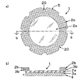
図1は、本発明のカテーテル固定具に係る実施形態の構成図を示し、a)図は正面図、b)図はa)図のb−b線に沿う断面図である。
略円形のカテーテル固定具1は、薄いプラスチックフィルムからなる基材2の底面の少なくとも一部分を被覆する粘着剤層3(この実施形態では基材底面の全面を被覆)と、この粘着剤層3の表面から剥離可能な粘着剤保護層4とを備えた構成を有している。基材2の周縁部には、カテーテルを沿わすための切欠き部20が所定の間隔をおいて形成されている。本実施形態においては、弧状の切欠き部20が、45°の間隔をおいて8箇所形成されている。一方、2つの弧状の切欠き部20に挟まれた部分5が、8箇所の略台形の形状を有した部分を形成している。つまり、2つの弧状の切欠き部に挟まれた部分5は、基材周縁を上底、それに対向する部分を下底と見た場合に、下底よりも短い上底を有する略等脚台形の形状を形成している。
Based on FIGS. 1-6, embodiment of this invention is described below. In addition, the common part of each embodiment demonstrates using the code | symbol of the same number.
FIG. 1: shows the block diagram of embodiment which concerns on the catheter fixture of this invention, a) A figure is a front view, b) A figure is sectional drawing which follows the bb line | wire of a) figure.
The substantially
図2は、本発明のカテーテル固定具に係る図1とは異なる実施形態の構成図を示し、a)図は正面図、b)図はa)図のb−b線に沿う断面図である。
図2の実施形態は、 HYPERLINK "javascript:fGetImage('000003','図1','K1');" 図1の実施形態よりも基材2及び粘着剤層3が薄く形成され、基材2の上面に支持体6が仮着された点が図1の実施形態と異なる。支持体6は、薄いプラスチックフィルムからなる基材2を貼付するときに、基材2のしわ発生を防止するために基材2の上面に仮着されており、カテーテル固定具1を所定の部位に貼付した後に支持体6の端部に設置されたタブ7を持って容易に剥離することができる。
本実施形態においては、弧状の切欠き部20が、45°の間隔をおいて(1箇所のみ90°の間隔)7箇所形成されている。また、2つの弧状の切欠き部20に挟まれた部分5が、6箇所の略等脚台形の形状を有した部分を形成している。
FIG. 2: shows the block diagram of embodiment different from FIG. 1 which concerns on the catheter fixture of this invention, a) A figure is a front view, b) A figure is sectional drawing which follows the bb line of a) figure. .
In the embodiment of FIG. 2, HYPERLINK “javascript: fGetImage ('000003', 'FIG. 1', 'K1');" The
In the present embodiment, the arc-
図3は、本発明のカテーテル固定具に係る図1と平面形状が異なる実施形態の正面図である。平面形状以外は、図1の実施形態と同様の構成を有する。
図3a)の実施形態は、カテーテル固定具1の平面形状が全体として略楕円形に形成され、弧状の切欠き部20が、30°の間隔をおいて12箇所形成されている。また、2つの弧状の切欠き部20に挟まれた部分5が、12箇所の略等脚台形の形状を有した部分を形成している。
図3b)の実施形態は、カテーテル固定具1の全体形状が略円形に形成され、異なる大きさを有する弧状の切欠き部21、22、23が、60°の間隔をおいて6箇所形成されている。本実施形態では、互いに対向する位置に同じ大きさの弧状の切欠き部が位置するように、切欠き部が設けられている。また、2つの弧状の切欠き部に挟まれた部分5が、6箇所の略台形の形状を有した部分を形成している。
図3b)の実施形態は、治療方法等の違いによって直径の異なるカテーテルを使用する場合でも、その直径のカテーテルに最もフィットし易い切欠き部を選択できるというメリットがある。
FIG. 3 is a front view of an embodiment of the catheter fixture according to the present invention that is different from FIG. 1 in plan view. Except for the planar shape, it has the same configuration as the embodiment of FIG.
In the embodiment of FIG. 3 a), the planar shape of the
In the embodiment of FIG. 3b), the overall shape of the
The embodiment of FIG. 3b) has an advantage that even when a catheter having a different diameter is used due to a difference in a treatment method or the like, a notch portion that is most easily fitted to the catheter having the diameter can be selected.
図4は、本発明のカテーテル固定具に係る図1とは異なる実施形態の構成図を示し、a)図は正面図、b)図はa)図のb−b線に沿う断面図である。
図4の実施形態は、基材が積層基材で形成されている点が図1の実施形態と異なる。即ち、図4の実施形態の基材は、底面に粘着剤層3aが被覆されたプラスチックフィルム基材2aと不織布等からなる繊維基材2bとの積層基材であって、リング状の繊維基材2bが、粘着剤層3bによって、プラスチックフィルム基材2aの周縁部に固定された構成を有する。そして、基材の周縁部を形成する繊維基材2bに、カテーテルを沿わすための切欠き部20が設けられている。
本実施形態においては、弧状の切欠き部20が、45°の間隔をおいて8箇所形成されている。また、2つの弧状の切欠き部20に挟まれた部分5が、8箇所の略等脚台形の形状を有した部分を形成している。
図4の実施形態は、カテーテルの穿刺部にあたる基材の中心部分がプラスチックフィルムで形成されているため、感染し易い穿刺部の観察が容易であり、さらに基材の周縁部を繊維基材で形成することで、プラスチックフィルム基材単独とする場合よりもカテーテルの固定性が良好となり、カテーテルの可動を抑制することができる。
FIG. 4: shows the block diagram of embodiment different from FIG. 1 which concerns on the catheter fixture of this invention, a) A figure is a front view, b) A figure is sectional drawing which follows the bb line of a) figure. .
The embodiment of FIG. 4 differs from the embodiment of FIG. 1 in that the substrate is formed of a laminated substrate. That is, the substrate of the embodiment of FIG. 4 is a laminated substrate of a
In the present embodiment, the arc-shaped
In the embodiment of FIG. 4, since the central portion of the base material corresponding to the puncture portion of the catheter is formed of a plastic film, it is easy to observe the puncture portion that is easily infected, and the peripheral portion of the base material is made of a fiber base material. By forming, the fixing property of the catheter becomes better than when the plastic film base material is used alone, and the movement of the catheter can be suppressed.
図5は、本発明のカテーテル固定具の実際の使用状態を示す図であり、カテーテル固定具によりカテーテル9を固定した状態を示す。図5の実施形態は、図2に示した実施形態のカテーテル固定具において粘着剤層と粘着剤保護層との間に吸収性パッド8を設けたものであり、本図においては、支持体6を基材2の上面から既に剥がした状態を示している。
カテーテル9の穿刺部から血液や滲出液がしみでる場合があるが、これらの血液や滲出液を放置しておくと、そこに皮膚常在菌などが増殖し、感染源となる恐れがある。そのため、本発明のカテーテル固定具は、感染の発生を防止するために、穿刺部の周囲(基材の中央部)に上記吸収性パッド8を設けるが、このパッドは、血液、滲出等の液体吸収性のパッドとすることが好ましい。この吸収性パッドは、カテーテルの穿刺部が観察できるようにリング状であることが好ましく、さらに後述するような抗菌処理が施されていることが好ましい。
FIG. 5 is a diagram showing an actual use state of the catheter fixture of the present invention, and shows a state where the catheter 9 is fixed by the catheter fixture. In the embodiment of FIG. 5, the absorbent pad 8 is provided between the adhesive layer and the adhesive protective layer in the catheter fixture of the embodiment shown in FIG. Is already peeled off from the upper surface of the
Blood or exudate may ooze out from the puncture portion of the catheter 9, but if these blood and exudate are left unattended, skin resident bacteria may grow there and become a source of infection. Therefore, in order to prevent the occurrence of infection, the catheter fixture of the present invention is provided with the absorbent pad 8 around the puncture part (center part of the base material). This pad is a liquid such as blood or exudate. It is preferable to use an absorbent pad. The absorbent pad is preferably in a ring shape so that the puncture portion of the catheter can be observed, and is preferably subjected to antibacterial treatment as described later.
図6は、カテーテル固定具の基材周縁部に貼付する補助ストリップ10について説明するための図である。図6a)は、図5の実施形態に示したカテーテル固定具において補助ストリップ10を貼付した使用状態を示す図で、図6のb)〜e)は、補助ストリップの形状のバリエーションを示した図である。
補助ストリップ10には、その周縁部にカテーテルを沿わすための切欠き部200が形成されている。補助ストリップ10は、その切欠き部200の凹みを、カテーテル固定具の切欠き部20の凹みと対向させるように、カテーテル固定具の基材周縁部に貼付することが好ましい。即ち、カテーテル固定具の基材周縁部から飛び出したカテーテル9を、カテーテル固定具の切欠き部20と、補助ストリップ10の切欠き部200とで挟み込むようにカテーテルを固定することが好ましい。本図では、補助ストリップ10を、カテーテル9の下側に入れ、カテーテル固定具1の基材周縁部の上から基材2を押さえつけるように貼付しているが、補助ストリップ10をカテーテル9の上から貼付しても良い。このような補助ストリップを使用することで、カテーテル固定具の基材周縁部の剥がれ、浮きがさらに起こり難くなるので、カテーテルの位置ずれや、菌の侵入をより確実に防ぐことが可能となる。
FIG. 6 is a diagram for explaining the
The
本発明のカテーテル固定具1の形状は、円形、楕円形や、三角形、長方形、菱形等の多角形等が利用でき、これらの形状を適宜組み合わせた形状にすることもできる。カテーテル固定具の形状は、カテーテルと切欠き部との位置合わせが容易な略円形、略楕円形が好ましく、略円形であることが特に好ましい。
As the shape of the
基材周縁部に設けるカテーテルを沿わすための切欠き部は、30°〜160°の間隔をおいて3〜12箇所形成されていることが好ましく、30°〜75°の間隔をおいて6〜12箇所形成されていることがさらに好ましい。切欠き部を設ける間隔は、上記角度の範囲内であれば等間隔でも、複数の異なる角度間隔でもよいが、等間隔に設けることが好ましい。切欠き部を上記範囲の間隔、個数で設置することにより、カテーテルとカテーテル固定具との位置合わせが容易となり、また、カテーテル固定具を凹凸や湾曲の大きい部位に貼付した場合でも、基材の周縁部がそれらの部位になじみ易く、カテーテルとの密着性も高まるため、カテーテル固定具にシワや剥がれが発生しにくくなる。
切欠き部を設ける間隔の角度、個数としては、前記図1〜6の実施形態に示した態様が適用できるが、これらの態様以外にも、ニーズに応じて種々の態様が適用できる。例えば、100°、100°、160°の間隔をおいて3箇所の切欠き部を形成する態様、75°、45°、75°、45°、75°、45°の間隔をおいて6箇所の切欠き部を形成する態様等である。なお、ここで言う切欠き部を設ける間隔の角度とは、円周上に全ての切欠き部の中心が存在する円又は楕円を仮定した場合に、その円又は楕円の中心を基準とした隣り合う2箇所の切欠き部の角度間隔である。
It is preferable that 3 to 12 notches are provided at intervals of 30 ° to 160 °, and 6 are provided at intervals of 30 ° to 75 °. More preferably, it is formed at -12 locations. The intervals at which the notches are provided may be equal intervals or a plurality of different angle intervals as long as they are within the above angle range, but are preferably provided at equal intervals. By setting the notches at intervals and numbers in the above range, it is easy to align the catheter and the catheter fixture, and even when the catheter fixture is affixed to an uneven or curved part, Since the peripheral edge portion is easily adapted to these parts and the adhesion to the catheter is increased, wrinkles and peeling are less likely to occur in the catheter fixture.
As the angle and the number of intervals at which the notch portions are provided, the modes shown in the embodiments of FIGS. 1 to 6 can be applied, but various modes can be applied according to needs other than these modes. For example, an embodiment in which three notches are formed at intervals of 100 °, 100 °, and 160 °, and six locations at intervals of 75 °, 45 °, 75 °, 45 °, 75 °, and 45 ° And a notch portion. Here, the angle of the interval at which the notch is provided is an adjacent circle or ellipse based on the center of the circle or ellipse, assuming a circle or ellipse in which the centers of all notches are present on the circumference. This is the angular interval between the two notch portions.
基材周縁部に設けるカテーテルを沿わすための切欠き部の形状は、弧状、スリット状、などが利用できるが、弧状が好ましい。切欠き部を弧状とする場合には、半径3〜30mmの円の半円部分で切欠き部分を形成することが、カテーテル等への密着性、取扱い性の観点から好ましい。また、弧状の切欠き部2箇所に挟まれた基材部分を、基材周縁を上底、それに対向する部分を下底と見た場合に、下底よりも短い上底を有する略等脚台形の形状とすることが特に好ましい。カテーテルに牽引力が加わった場合に、カテーテル固定具の周縁に力が集中し、そこをきっかけに基材の剥がれ等が起こり易くなるが、基材周縁にこのような略等脚台形部分を設けることにより、カテーテルや皮膚に基材周縁部が密着し易くなり、カテーテルの固定性が高まる。さらに、基材周縁部に略等脚台形部分があることで、固定具を剥離する際にもその台形部分を摘んで剥がすことができるため、取り扱い性が良好なものとなる。
基材周縁部に設けるカテーテルを沿わすための複数の切欠き部は、全てを同じ形状、大きさにしても良いし、複数の異なる大きさ又は形状の切欠き部としてもよい。
As the shape of the cutout portion along the catheter provided on the peripheral edge portion of the substrate, an arc shape, a slit shape, or the like can be used, but an arc shape is preferable. In the case where the notch is formed in an arc shape, it is preferable to form the notch with a semicircular portion of a circle having a radius of 3 to 30 mm from the viewpoint of adhesion to a catheter or the like and handleability. Further, when the base material portion sandwiched between the two arc-shaped cutout portions is viewed as the base edge of the base material and the portion facing it as the lower base, the substantially equal leg having an upper base shorter than the lower base. A trapezoidal shape is particularly preferable. When a traction force is applied to the catheter, the force concentrates on the peripheral edge of the catheter fixture, and the base material is likely to peel off as a result, but such a substantially isosceles trapezoidal part should be provided on the peripheral edge of the base material. As a result, the peripheral edge of the base material is easily brought into close contact with the catheter and the skin, and the fixation of the catheter is enhanced. Furthermore, since there is a substantially isosceles trapezoidal portion at the periphery of the base material, the trapezoidal portion can be picked and peeled when the fixture is peeled off, so that the handleability is good.
The plurality of cutout portions along the catheter provided on the peripheral edge portion of the base material may all have the same shape and size, or may be cutout portions having a plurality of different sizes or shapes.
本発明に用いられるカテーテル固定具の基材としては、貼付部位に追従し得る柔軟性、伸縮性を有し、カテーテルの穿刺部の観察が容易な透明又は半透明のプラスチックフィルムが好適に使用でき、例えば、ポリウレタン、ポリエーテルポリエステル、ポリアミド、ポリエチレン、ポリプロピレン、アクリル系重合体、オレフィン系共重合体等が使用できる。これらのうち、ポリウレタン、ポリエーテルポリエステル、ポリアミド等は水蒸気透過性が良好で、不感蒸散等を妨げることが少ないため、特に好ましい。プラスチックフィルム基材の厚さとしては、10〜150μmの範囲が好ましく、特に15〜75μmの範囲が好ましい。
また、カテーテル固定具の基材としては、上記プラスチックフィルム以外にも、例えば、不織布、編布、織布などの繊維基材やフォーム基材を使用することもでき、これらの基材をプラスチックフィルム等に積層した積層基材を使用することもできる。好ましい積層基材は、プラスチックフィルム基材と繊維基材との積層基材であり、カテーテルの穿刺部の観察を容易とし、且つカテーテルの固定性を高めるために、繊維基材はカテーテル固定具の周縁部にリング状に設置し、繊維基材の部分にカテーテルを沿わすための切欠き部を設けることが特に好ましい。繊維基材の厚さは、15〜1,500μmの範囲が好ましく、特に15〜500μmの範囲が好ましい。
As the base material of the catheter fixture used in the present invention, a transparent or translucent plastic film that has flexibility and stretchability that can follow the application site and can easily observe the puncture portion of the catheter can be suitably used. For example, polyurethane, polyether polyester, polyamide, polyethylene, polypropylene, acrylic polymer, olefin copolymer and the like can be used. Of these, polyurethane, polyether polyester, polyamide, and the like are particularly preferable because they have good water vapor permeability and do not disturb insensitive transpiration. As a thickness of a plastic film base material, the range of 10-150 micrometers is preferable, and the range of 15-75 micrometers is especially preferable.
In addition to the plastic film, for example, a fiber substrate such as a nonwoven fabric, a knitted fabric, or a woven fabric, and a foam substrate can be used as the catheter fixture base material. It is also possible to use a laminated base material laminated in the same manner. A preferred laminated base material is a laminated base material of a plastic film base material and a fiber base material. In order to facilitate observation of the puncture portion of the catheter and to enhance the fixation of the catheter, the fiber base material is used for the catheter fixture. It is particularly preferable to provide a ring-like portion at the peripheral portion and provide a notch portion for placing the catheter along the fiber base portion. The thickness of the fiber substrate is preferably in the range of 15 to 1,500 μm, particularly preferably in the range of 15 to 500 μm.
本発明に用いられる粘着剤層としては、種々の感圧性粘着剤が使用でき、例えばアクリル系、シリコーン系、ウレタン系、ビニルエーテル系、天然ゴム系、合成ゴム系等の感圧性粘着剤が挙げられる。中でも、アクリル系、シリコーン系が好ましく、シリコーン系、テフロン(登録商標)系のカテーテルに対して良好な粘着性を有するシリコーン系が特に好ましい。また、これらの感圧性粘着剤に、カルボキシメチルセルロース、カラヤガム、ペクチン、ゼラチン等の親水性高分子化合物を加えた、いわゆるハイドロコロイド粘着剤を使用すると、汗やカテーテルの穿刺部からの滲出液等を吸収することができ、蒸れによるカブレや掻痒感を軽減することができる。
粘着剤層は、その厚さが5〜500μmであることが好ましく、5〜200μmであることが更に好ましい。また、粘着剤層の塗工重量でいうと10〜500g/m2の範囲が好ましく、20〜150g/m2の範囲が更に好ましい。粘着剤層の厚さ、塗工重量がこの範囲内にあることにより、貼付時に適度な粘着力を示し、カテーテルや皮膚に対する密着性及び追従性にも優れ、良好な透湿度を得ることができる。
As the pressure-sensitive adhesive layer used in the present invention, various pressure-sensitive pressure-sensitive adhesives can be used, and examples thereof include pressure-sensitive pressure-sensitive adhesives such as acrylic, silicone, urethane, vinyl ether, natural rubber, and synthetic rubber. . Among them, acrylic and silicone systems are preferable, and silicone systems having good adhesiveness to silicone and Teflon (registered trademark) catheters are particularly preferable. In addition, when these so-called hydrocolloid adhesives are used, in which hydrophilic polymer compounds such as carboxymethylcellulose, karaya gum, pectin, and gelatin are added to these pressure-sensitive adhesives, they absorb sweat and exudates from the catheter puncture site. This can reduce irritation and rash caused by stuffiness.
The thickness of the pressure-sensitive adhesive layer is preferably 5 to 500 μm, and more preferably 5 to 200 μm. Further, preferably in the range of 10 to 500 g / m 2 in terms of the coating weight of the adhesive layer, more preferably in the range of 20 to 150 g / m 2. When the thickness of the pressure-sensitive adhesive layer and the coating weight are within this range, it exhibits an appropriate pressure-sensitive adhesive force at the time of application, has excellent adhesion and followability to the catheter and the skin, and can obtain good moisture permeability. .
本発明に用いられる粘着剤保護層としては、公知の剥離紙、剥離フィルムが利用でき、紙やフィルムの表面にシリコーン樹脂処理やフッソ樹脂処理等を施したものを利用できる。
また、基材として薄くて柔軟なプラスチックフィルムを用いる場合、基材の上面に支持体を仮着することが好ましい。本発明に用いられる支持体は、基材を貼付するときに基材のしわ発生を防止する程度の硬さを有するものであればよく、ポリエチレン、ポリプロピレン、ポリアミド、エチレン・酢酸ビニル共重合体、ポリエステル等のプラスチック材料、紙、不織布等が利用できる。この支持体は、基材の貼付時に基材を定型状態に維持できれば必ずしも基材の上面の全面を覆う必要はなく、例えば、基材の周縁部だけを窓枠状に被覆し、基材の中央部は被覆しない形態にすることもできる。支持体を基材に仮着する方法としては、接着、熱圧着、共押し出しによる仮着等、公知の方法を使用することができる。
As the pressure-sensitive adhesive protective layer used in the present invention, a known release paper or release film can be used, and a paper or film surface subjected to a silicone resin treatment or a fluorine resin treatment can be used.
Moreover, when using a thin and flexible plastic film as a base material, it is preferable to temporarily attach a support body to the upper surface of a base material. The support used in the present invention may be any support as long as it has a hardness that prevents the occurrence of wrinkling of the substrate when the substrate is affixed, polyethylene, polypropylene, polyamide, ethylene / vinyl acetate copolymer, Plastic materials such as polyester, paper, and non-woven fabric can be used. The support does not necessarily need to cover the entire upper surface of the base material if the base material can be maintained in a fixed state when the base material is applied. The central part can be formed in a non-covered form. As a method for temporarily attaching the support to the substrate, a known method such as adhesion, thermocompression bonding, temporary attachment by coextrusion, or the like can be used.
本発明のカテーテル固定具は、カテーテルの穿刺部からの血液や滲出液を吸収し感染の発生を予防するために、粘着剤層と粘着剤保護層との間に液体吸収性のパッドを設けることが好ましい。吸収性パッドは、カテーテルの穿刺部が観察できるようにリング状に形成し、穿刺部の周囲に設置できるよう基材の中央部に設けることが好ましい。
吸収性パッドは、繊維、フォームなどから形成することができ、菌の増殖を抑制するために、抗菌剤等で抗菌処理したものであることが好ましい。抗菌剤としては、亜鉛、銀、銅等の金属化合物、第4級アンモニウム化合物、ヨウ素化合物、グルコン酸クロルヘキシジン等の公知の物質を使用することができる。
The catheter fixture of the present invention is provided with a liquid-absorbing pad between the pressure-sensitive adhesive layer and the pressure-sensitive adhesive protective layer in order to absorb blood and exudate from the puncture portion of the catheter and prevent the occurrence of infection. Is preferred. The absorbent pad is preferably formed in a ring shape so that the puncture portion of the catheter can be observed, and provided at the center of the base material so that it can be placed around the puncture portion.
The absorbent pad can be formed from fibers, foams, etc., and preferably has been subjected to antibacterial treatment with an antibacterial agent or the like in order to suppress the growth of bacteria. As the antibacterial agent, known substances such as metal compounds such as zinc, silver and copper, quaternary ammonium compounds, iodine compounds and chlorhexidine gluconate can be used.
吸収性パッドの抗菌処理としては、繊維等に抗菌剤を吸着、練り込み、化学結合させる処理などを利用することができるが、アニオン性官能基を有する繊維において、そのアニオン性官能基の一部に抗菌性金属塩又は第4級アンモニウム塩を形成させる処理をしたものが好ましい。
アニオン性官能基を有する繊維としては、カルボキシアルキル化セルロース繊維、ポリアミド繊維、毛(羊毛、獣毛等)、絹等のカルボキシ基を有する繊維が好ましく、カルボキシメチル化セルロース繊維が特に好ましい。
抗菌性金属塩としては、亜鉛塩、銀塩、銅塩とすることが好ましく、白色のパッドを変色させることがない亜鉛塩とすることが特に好ましい。
第4級アンモニウム塩としては、セチルピリジニウム塩、ベンザルコニウム塩、ベンゼトニウム塩とすることが好ましい。
本発明の吸収性パッドは、リング状であり、カルボキシメチル化セルロース繊維のカルボキシ基に抗菌性金属として亜鉛塩又は銀塩を形成したものであることが特に好ましい。
As an antibacterial treatment of the absorbent pad, a treatment of adsorbing, kneading, and chemically bonding an antibacterial agent to a fiber or the like can be used, but in a fiber having an anionic functional group, a part of the anionic functional group What processed to form an antibacterial metal salt or a quaternary ammonium salt is preferable.
As the fiber having an anionic functional group, a fiber having a carboxy group such as carboxyalkyl cellulose fiber, polyamide fiber, hair (wool, animal hair, etc.) and silk is preferable, and carboxymethyl cellulose fiber is particularly preferable.
The antibacterial metal salt is preferably a zinc salt, a silver salt, or a copper salt, and particularly preferably a zinc salt that does not discolor the white pad.
The quaternary ammonium salt is preferably a cetylpyridinium salt, a benzalkonium salt, or a benzethonium salt.
The absorbent pad of the present invention has a ring shape, and it is particularly preferable that a zinc salt or a silver salt is formed as an antibacterial metal on the carboxy group of the carboxymethylated cellulose fiber.
カテーテル固定具の基材周縁部に貼付する補助ストリップは、その周縁部にカテーテルを沿わすための切欠き部を有する。補助ストリップの切欠き部と、カテーテル固定具の切欠き部とを互いに対向させ、カテーテルを2つの切欠き部の凹みの間に挟み込むようにして固定することで、より確実な固定が可能となる。
補助ストリップは、基材と粘着剤層と粘着剤保護層とからなるテープ状の薄片で構成することができ、その材料は、前述のカテーテル固定具の基材と粘着剤層と粘着剤保護層に使用する材料と同様のものを使用することができる。また、補助ストリップは、カテーテル固定具の基材周縁部に設けられた1個の切欠き部及びその周辺を覆い得る大きさ、形状を有していればよく、略長方形、ブーメラン型などに形成することができる。
補助ストリップの周縁部に形成するカテーテルを沿わすための切欠き部は、前述のカテーテル固定具の基材周縁部に設ける切欠き部と同様の形状、大きさのものを採用することができる。
The auxiliary strip attached to the peripheral part of the base material of the catheter fixture has a notch for placing the catheter along the peripheral part. By fixing the notch portion of the auxiliary strip and the notch portion of the catheter fixture opposite to each other and fixing the catheter so as to be sandwiched between the recesses of the two notch portions, more reliable fixation is possible. .
The auxiliary strip can be composed of a tape-like thin piece comprising a base material, an adhesive layer, and an adhesive protective layer, and the material is the base material, the adhesive layer, and the adhesive protective layer of the aforementioned catheter fixture. The same materials as used in the above can be used. In addition, the auxiliary strip only needs to have a size and shape that can cover one notch provided on the peripheral edge of the base material of the catheter fixture and the periphery thereof, and is formed in a substantially rectangular shape, boomerang type, or the like. can do.
As the notch for laying the catheter formed on the peripheral edge of the auxiliary strip, one having the same shape and size as the notch provided on the peripheral edge of the base material of the catheter fixture described above can be adopted.
1 カテーテル固定具
2 基材
2a プラスチックフィルム基材
2b 繊維基材
3,3a,3b 粘着剤層
4 粘着剤保護層
5 切欠き部に挟まれた部分
6 支持体
7 タブ
8 吸収性パッド
9 カテーテル
10 補助ストリップ
20〜23,200 切欠き部
DESCRIPTION OF
Claims (9)
前記基材の周縁部にカテーテルを沿わすための切欠き部が30°〜160°の間隔をおいて3〜12箇所形成されていることを特徴とするカテーテル固定具。 In a catheter fixture comprising: a base material having a top surface and a bottom surface; an adhesive layer that covers at least a part of the bottom surface of the substrate; and an adhesive protective layer that covers the surface of the adhesive layer and is peelable.
3. A catheter fixture having 3 to 12 notches for placing the catheter along the peripheral edge of the base material at intervals of 30 ° to 160 °.
前記基材の周縁部にカテーテルを沿わすための切欠き部が30°〜160°の間隔をおいて3〜12箇所形成されていることを特徴とするカテーテル固定具。 A base material made of a plastic film having an upper surface and a bottom surface, an adhesive layer that covers at least a part of the bottom surface of the base material, an adhesive protective layer that covers and peels the surface of the adhesive layer, and an upper surface of the base material In a catheter fixture comprising a temporarily attached support,
3. A catheter fixture having 3 to 12 notches for placing the catheter along the peripheral edge of the base material at intervals of 30 ° to 160 °.
Priority Applications (1)
| Application Number | Priority Date | Filing Date | Title |
|---|---|---|---|
| JP2007020045A JP4867025B2 (en) | 2007-01-30 | 2007-01-30 | Catheter fixture |
Applications Claiming Priority (1)
| Application Number | Priority Date | Filing Date | Title |
|---|---|---|---|
| JP2007020045A JP4867025B2 (en) | 2007-01-30 | 2007-01-30 | Catheter fixture |
Publications (2)
| Publication Number | Publication Date |
|---|---|
| JP2008183244A JP2008183244A (en) | 2008-08-14 |
| JP4867025B2 true JP4867025B2 (en) | 2012-02-01 |
Family
ID=39726667
Family Applications (1)
| Application Number | Title | Priority Date | Filing Date |
|---|---|---|---|
| JP2007020045A Active JP4867025B2 (en) | 2007-01-30 | 2007-01-30 | Catheter fixture |
Country Status (1)
| Country | Link |
|---|---|
| JP (1) | JP4867025B2 (en) |
Families Citing this family (12)
| Publication number | Priority date | Publication date | Assignee | Title |
|---|---|---|---|---|
| US9820888B2 (en) | 2006-09-26 | 2017-11-21 | Smith & Nephew, Inc. | Wound dressing |
| GB0723855D0 (en) | 2007-12-06 | 2008-01-16 | Smith & Nephew | Apparatus and method for wound volume measurement |
| US8298200B2 (en) | 2009-06-01 | 2012-10-30 | Tyco Healthcare Group Lp | System for providing continual drainage in negative pressure wound therapy |
| GB0902368D0 (en) | 2009-02-13 | 2009-04-01 | Smith & Nephew | Wound packing |
| US8791315B2 (en) | 2010-02-26 | 2014-07-29 | Smith & Nephew, Inc. | Systems and methods for using negative pressure wound therapy to manage open abdominal wounds |
| GB201015656D0 (en) | 2010-09-20 | 2010-10-27 | Smith & Nephew | Pressure control apparatus |
| US9084845B2 (en) | 2011-11-02 | 2015-07-21 | Smith & Nephew Plc | Reduced pressure therapy apparatuses and methods of using same |
| HUE047600T2 (en) | 2012-05-23 | 2020-04-28 | Smith & Nephew | Apparatuses for negative pressure wound therapy |
| HUE033329T2 (en) | 2012-08-01 | 2017-11-28 | Smith & Nephew | Wound dressing |
| RU2015106111A (en) * | 2012-08-01 | 2016-09-27 | СМИТ ЭНД НЕФЬЮ ПиЭлСи | Wound dressing and method of treatment |
| US10493184B2 (en) | 2013-03-15 | 2019-12-03 | Smith & Nephew Plc | Wound dressing and method of treatment |
| EP3644914A1 (en) | 2017-06-30 | 2020-05-06 | T J Smith & Nephew Limited | Negative pressure wound therapy apparatus |
Family Cites Families (7)
| Publication number | Priority date | Publication date | Assignee | Title |
|---|---|---|---|---|
| US3918446A (en) * | 1974-05-03 | 1975-11-11 | E Med Corp | Securement device for intravenous catheter and its tubing |
| JPS6362123A (en) * | 1986-08-29 | 1988-03-18 | 豊田合成株式会社 | Object discriminator by light reflection |
| JPS6385248A (en) * | 1986-09-26 | 1988-04-15 | Matsuoka Gijutsu Jimusho:Kk | Sub-chamber type diesel engine with exhaust gas recircualating device |
| US4935011A (en) * | 1987-09-29 | 1990-06-19 | City Of Hope | Sheath for intravenous needle |
| EP0873098A1 (en) * | 1996-01-12 | 1998-10-28 | Smith & Nephew plc | Wound dressing |
| JPH1085253A (en) * | 1996-09-20 | 1998-04-07 | Mitsubishi Plastics Ind Ltd | Support for medical instrument indwelled in living body |
| GB0308311D0 (en) * | 2003-04-10 | 2003-05-14 | Bristol Myers Squibb Co | Wound dressing |
-
2007
- 2007-01-30 JP JP2007020045A patent/JP4867025B2/en active Active
Also Published As
| Publication number | Publication date |
|---|---|
| JP2008183244A (en) | 2008-08-14 |
Similar Documents
| Publication | Publication Date | Title |
|---|---|---|
| JP4867025B2 (en) | Catheter fixture | |
| JP7304868B2 (en) | Fixed dressings with compatible margins | |
| US10940049B2 (en) | Conformable medical dressing | |
| JP6275718B2 (en) | Integrated bandage device | |
| US11246761B2 (en) | Conformable wound dressing and delivery system | |
| JP6284958B2 (en) | All-in-one antibacterial bandage for catheter coverage | |
| CN104994817B (en) | Medical dressing with multiple adhesives | |
| US20160193452A1 (en) | Medical dressing comprising a flap | |
| US20070055205A1 (en) | Protective dressing and methods of use thereof | |
| JP5092105B2 (en) | Catheter fixture and pad for catheter fixture | |
| JP2009017941A (en) | Catheter fixing appliance and skin pasting-on member for use in fixing catheter to skin | |
| JP6060355B2 (en) | Catheter fixture | |
| US20160008576A1 (en) | Percutaneous port guard dressing | |
| US20230277385A1 (en) | Conformable medical dressing | |
| JP5282834B2 (en) | Skin patch for catheter fixation | |
| BR112019007011B1 (en) | MEDICAL ARTICLE UNDERSTANDING A WOUND DRESSING | |
| JPH10328310A (en) | Catheter fixing apparatus |
Legal Events
| Date | Code | Title | Description |
|---|---|---|---|
| A621 | Written request for application examination |
Free format text: JAPANESE INTERMEDIATE CODE: A621 Effective date: 20091210 |
|
| RD02 | Notification of acceptance of power of attorney |
Free format text: JAPANESE INTERMEDIATE CODE: A7422 Effective date: 20100125 |
|
| RD04 | Notification of resignation of power of attorney |
Free format text: JAPANESE INTERMEDIATE CODE: A7424 Effective date: 20100205 |
|
| RD03 | Notification of appointment of power of attorney |
Free format text: JAPANESE INTERMEDIATE CODE: A7423 Effective date: 20100212 |
|
| A977 | Report on retrieval |
Free format text: JAPANESE INTERMEDIATE CODE: A971007 Effective date: 20111005 |
|
| TRDD | Decision of grant or rejection written | ||
| A01 | Written decision to grant a patent or to grant a registration (utility model) |
Free format text: JAPANESE INTERMEDIATE CODE: A01 Effective date: 20111018 |
|
| A01 | Written decision to grant a patent or to grant a registration (utility model) |
Free format text: JAPANESE INTERMEDIATE CODE: A01 |
|
| A61 | First payment of annual fees (during grant procedure) |
Free format text: JAPANESE INTERMEDIATE CODE: A61 Effective date: 20111024 |
|
| R150 | Certificate of patent or registration of utility model |
Free format text: JAPANESE INTERMEDIATE CODE: R150 Ref document number: 4867025 Country of ref document: JP Free format text: JAPANESE INTERMEDIATE CODE: R150 |
|
| FPAY | Renewal fee payment (event date is renewal date of database) |
Free format text: PAYMENT UNTIL: 20141125 Year of fee payment: 3 |
|
| R250 | Receipt of annual fees |
Free format text: JAPANESE INTERMEDIATE CODE: R250 |
|
| R250 | Receipt of annual fees |
Free format text: JAPANESE INTERMEDIATE CODE: R250 |
|
| R250 | Receipt of annual fees |
Free format text: JAPANESE INTERMEDIATE CODE: R250 |
|
| R250 | Receipt of annual fees |
Free format text: JAPANESE INTERMEDIATE CODE: R250 |
|
| R250 | Receipt of annual fees |
Free format text: JAPANESE INTERMEDIATE CODE: R250 |
|
| R250 | Receipt of annual fees |
Free format text: JAPANESE INTERMEDIATE CODE: R250 |
|
| R250 | Receipt of annual fees |
Free format text: JAPANESE INTERMEDIATE CODE: R250 |
|
| R250 | Receipt of annual fees |
Free format text: JAPANESE INTERMEDIATE CODE: R250 |
|
| R250 | Receipt of annual fees |
Free format text: JAPANESE INTERMEDIATE CODE: R250 |
|
| R250 | Receipt of annual fees |
Free format text: JAPANESE INTERMEDIATE CODE: R250 |
|
| R250 | Receipt of annual fees |
Free format text: JAPANESE INTERMEDIATE CODE: R250 |